Fuel-Fired Vertical Tubeless Boilers - Seickel & · PDF fileFuel-Fired Vertical Tubeless...
8
Fuel-Fired Vertical Tubeless Boilers Fulton Classic (6-60HP), The EDGE (6-30HP) Horizontal and Vertical Condensate Return Systems and Blow-down Separators
Transcript of Fuel-Fired Vertical Tubeless Boilers - Seickel & · PDF fileFuel-Fired Vertical Tubeless...
Fuel-Fired Vertical Tubeless BoilersFulton Classic (6-60HP), The EDGE (6-30HP)
Horizontal and Vertical Condensate Return Systemsand Blow-down Separators
The thickness of the pressure vessel is no less
than 5/16” (7.94mm)
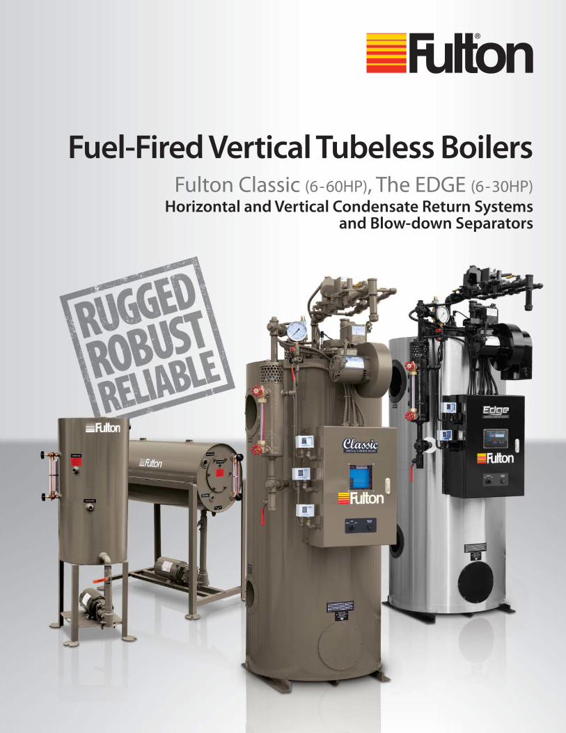
Since Fulton’s invention of the vertical tubeless boiler in 1949, Fulton has been the leading U.S. manufacturer of this type of boiler. For over 60 years, more than 100,000 boilers have been produced and distributed world-wide.
Every Fulton boiler is built and stamped to ASME Code and registered with the National Board of Boiler and Pressure Vessel Inspectors. Fulton boilers are UL listed boilers -- not just the burner or electrical components -- the entire boiler and they are CSA approved.
A vertical tubeless boiler is a relatively simple design, off ering years of trouble-free operationMany Fulton boilers over 30 years of age are still in operation today. There are no tubes or coils to rust or burn out periodically, therefore, no retubing costs, no downtime. No downtime means increased productivity.
Complete control panel box houses all necessary operating componentsThe 7800 Series Microprocessor based controls are standard. A trouble shooting display module is optional. Fulton’s commitment to continuous product improvement is refl ected in the effi ciency, quality, and ruggedness of these superior standard fuel-fi red boilers.
FULTON: AN INDUSTRY LEADER SINCE 1949All Fulton Boilers can be ordered with a polished stainless steel jacketAsk your Fulton distributor how little extra it can costfor stainless.
Unique features begin with simplicityThe furnace (pressure vessel) is, simply stated, a “pipe within a pipe”. The top mounted Fulton power burner sends a spinning cyclonic fl ame into and down the center furnace chamber.
858075
70Perc
ent o
f effi
cien
cy
TypicalCompetitor'sBoiler
FultonStandardBoiler
FultonFB-FBoiler
If you want more effi ciency with the same vertical tubeless design Fulton has The EDGE
and it does have the edge over the Classic. Fuel to steam effi ciencies in the low 80’s. The EDGE has the same time proven top mounted matched burner with the downward cyclonic fl ame and features the Fulton engineered Flue Gas Enhancing System (FGE). A highly effi cient two pass design, the Fulton FGE system works by using a massive heat transfer surface with high velocity fl ue gasses traveling over a cylindrical grid of heat convection fi ns. Through controlled velocities these fi ns transmit additional heat evenly to the outer side of the water vessel, creating high effi ciencies with lower stack temperatures.
Dramatic stack temp. reductionsWith the Fulton FB-F, The EDGE, stack temperatures can be from 100-150°F below standard two pass designs and have cut previous fuel bills in half!
Tp
nd
d
er
ts,
es nts
ng
ncy, ior
yextra it can costfor stainless.
Unique features begin with simplicityThe furnace (pressure vessel) is, simply stated, a “pipe within a pipe”. The top mounted Fulton power burner sends a spinning cyclonic fl ame into and down the center furnace chamber.
PePPrc
ento
feffi
cien
cy
anClalowprowifeaGaeffi systragahevehevelow
DrWitembeha
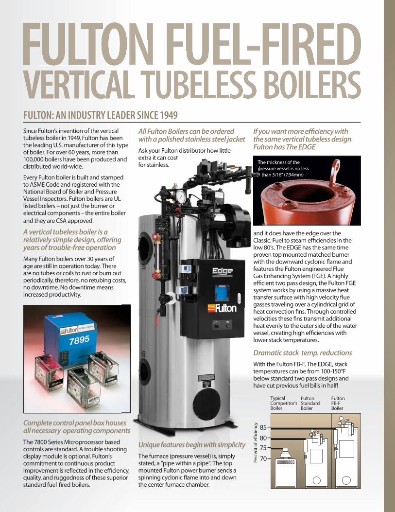
A LOOK INSIDE FULTON’SVERTICAL TUBELESS BOILERThe Fulton standard top fi redpower burner
The optional Fultonlow emissions burner.
(< 20PPM NOx and < 60PPM CO)
THE COMBUSTION PROCESS1 Air is drawn into the power
burner where it is mixed with fuel for optimum combustion. 2 The ignition assembly ignites the air/fuel mixture and sends a spinning cyclonic fl ame down the length of the furnace chamber, forming the fi rst pass. 3 Flame retainer rings increase occupancy time of the fl ue gases increasing heat transfer. 4 The fl ue gases are turned at the base of the chamber and return over the heat convection fi ns that surround the entire water jacket. This is the second pass, which transfers additional heat to the water in the vessel. The Edge model has more fi ns and an enhanced orientation to improve heat transfer. 5 The fl ue gases are then collected at the upper portion of the boiler and are expelled through the fl ue outlet.
FFultonurner.
PM CO)
SS
elel he /g of e
gs fl ue 4 basee the ndn
heen toue pper
pelled
1
2
4
5
Large Handholes
Water Inlet
High Temp Insulation
Blowdown Outlet
Control Panel Box
Steam Outlet
Complete Gas Train
3
3
Fulton fuel-fi red boilers can be ordered with combination fuel capabilities or be converted to combination fuels simply and economically.
All fuel-fi red boilers feature the Fulton designed and manufactured top mounted down fi red forced draft burner.

Classic Models FB-A 6 9.5 10 15 20 25 30 50 60
The EDGE Models FB-F 6 N/A 10 15 20 N/A 30 N/A N/A
Unit Size: HP 6 9.5 10 15 20 25 30 50 60Heights and Widths
(A) Boiler Height IN 57.5 67.5 63.5 69.5 72.5 74.5 82.5 87.5 93.5 MM 1461 1715 1613 1765 1842 1892 2096 2223 2375(B) Boiler Height With Trim and Fuel Train IN 75 85 80.5 86.5 92.5 94.5 102 106.5 120 MM 1905 2159 2045 2197 2350 2400 2591 2705 3048(C) Overall Depth Stack IN 44 39 46 47 60 60 67 78 78 to Burner Fan Housing MM 1118 991 1168 1194 1524 1524 1702 1981 1981(D) Boiler Diameter IN 26 26 28 30 39 39 46 55 55 MM 660 660 710 760 990 990 1170 1400 1400(E) Overall Width IN 33 33 33.5 35.5 43 43 49 57 57 with Water Column MM 838 838 851 902 1091 1091 1244 1448 1448(F) Flue Outlet Diameter IN 6 6 6 8 10 10 12 12 12 MM 152 152 152 203 254 254 305 305 305(G) To Center of Flue Outlet IN 52 62 58 63 66 66 73.5 79 85 MM 1320 1575 1473 1600 1675 1676 1867 2007 2159Minimum Clearances
(H) Clearance for Burner Removal *IN 82 92 86 92 96 98 106 114 124 MM 2083 2337 2184 2337 2438 2489 2692 2896 3150(I) Opening Required for Installation IN 26 26 28 30 39 39 46 55 55 With Water Column Removed MM 660 660 710 760 990 990 1170 1400 1400Front of Boiler IN 41 41 41 41 41 41 41 41 41 MM 1041 1041 1041 1041 1041 1041 1041 1041 1041Sides & Rear of Boiler IN 18 18 18 18 18 18 18 18 18 MM 914 914 914 914 914 914 914 914 914Weights
Approx. Shipping Weight LB 1700 1900 2000 2280 3400 3500 4780 6526 7280 KG 773 862 910 1036 1545 1588 2173 2966 3309
* This dimension is 6” less for oil-fi red units 6-50 HP and 12” less for oil-fi red units 60 HP. Add 6” for low emissions burner removal.
CLASSIC MODELS FBA, EDGE MODELS FBF
B
A
H
C
G
E
F
GAS HEADCAN PIVOT
360°
I
D
Side View Front View Top View

AND SPECIFICATIONSClassic Models FB-A 6 9.5 10 15 20 25 30 50 60
The EDGE Models FB-F 6 9.5 10 15 20 25 30 N/A N/A
Unit Size: HP 6 9.5 10 15 20 25 30 50 60Ratings* (Sea level to 3000 ft.)
Output 1,000 BTUHR 201 318 335 503 670 838 1,005 1,674 2,009 1,000 KCAL/HR 50.7 80.1 84.4 127 169 211 253 422 506Steam Output LB/HR 207 328 345 518 690 863 1,035 1,725 2,070 KG/HR 94 149 157 235 313 392 470 785 942Approximate Fuel Consumption at Rated Capacity+
Light Oil GPH 1.8 2.8 3.0 4.5 6 7.5 9 15.0 17.9 LPH 6.8 10.6 11.4 17.0 22.7 28.4 34.1 56.8 67.8Propane Gas (Classic) FT3/HR 100 159 168 251 335 419 502 837 1,004 M3/HR 2.8 4.5 4.8 7.1 9.5 11.9 14.2 23.7 28.4Natural Gas (Classic) FT3/HR 257 398 419 628 837 1,047 1,256 2,093 2,511 M3/HR 7.1 11.3 11.9 17.8 23.7 29.7 35.4 59.3 71.1Propane Gas (EDGE) FT3/HR 97 161 242 323 404 484 N/A N/A M3/HR 2.7 N/A 4.6 6.9 9.1 11.4 13.7 N/A N/ANatural Gas (EDGE) FT3/HR 242 384 403 606 807 1,009 1,210 N/A N/A M3/HR 6.9 10.8 11.4 17.2 22.9 28.6 34.4 N/A N/ANat. Gas Boiler Connection Size IN 1 1 1 1 1.25 1.25 1.5 1.5** 2 MM 25 25 25 25 32 32 38 38 51Burner Motor HP 3450 RPM/60 CY 1/3 gas 1.5 gas 1.5 gas 2850 RPM/50 CY 1/3 1/3 1/3 1/3 3/4 oil 3/4 3/4 2 oil 2 oilElectric Power Requirements (in Amps)
120V,60 CY, 1 Phase 5.2 5.2 5.2 5.2 5.2 gas 5.2 gas 9.2 9.2 oil 9.2 oil
240V, 50/60 CY, 1 Phase 2.6 2.6 2.6 2.6 2.6 gas 2.6 gas 4.6 8.9 gas 8.9 gas 4.6 oil 4.6 oil 9.5 oil 9.5 oil 208V, 50/60 CY, 3 Phase 1.9 1.9 1.9 1.9 1.9 gas 1.9 gas 3.1 4.4 gas 4.4 gas
3.1 oil 3.1 oil 5.7 oil 5.7 oil 240V, 50/60 CY, 3 Phase 1.6 1.6 1.6 1.6 1.6 gas 1.6 gas 2.8 4.2 gas 4.2 gas
2.8 oil 2.8 oil 5.4 oil 5.4 oil 480V, 50/60 CY, 3 Phase .8 .8 .8 .8 0.8 gas 0.8 gas 1.4 2.1 gas 2.1 gas
1.4 oil 1.4 oil 2.7 oil 2.7 oilWater Content
GALLONS 16 16 24 39 77 82 170 245 270 LITERS 61 61 91 148 292 310 644 927 1,022
+ Consumption based on Light Oil 140,000 BTU/G/ Natural Gas 1010 BTU/ft3; Propane 2530 BTU/ft3. * All ratings from 0 PSIG and at 212°F. • Consult Factory • ** 2”/51mm IRI and CSA • N/A-Not AvailableSpecifi cations and Dimensions are approximate. We reserve the right to change specifi cations and/or dimensions without notice. Diagram for guidance purposes only. Comprehensive details of dimensions, connections, etc. for each model are given on product dimension data sheets available from Fulton.
SafetyValve
VentReturn Water
Column and
SightGlass
Cold WaterSupply
ElectricControlPanel
SightGlass
Union
Pump/Strainer
CondensateReturnTank
BlowdownSeparator
Gas-Fired
Steam BoilerShutOff
ValveCheckValves
FastOpening
Valve
BlowdownValve
Union
Vent
CheckValve
Shut OffValve
Cold WaterInlet
Thermometer
Drain
OutletTo Drain
HandHole
Condensate return tank should be vented and have a capacity suffi cient to satisfy boiler consumption and maintain proper return tank temperature. Vent pipe should not be down-sized (may cause pressure build up in the condensate tank). Return pipes must not be insulated.
See Return System Instruction Manual.Optional barometric damper is recommendedfor most installations.
Boiler, Condensate Tank, and Blow-Down Separator
Note: High pressure boilers ordered with an extra pressure control for night heating have less than rated output while operating at low pressure.
NoNoNoNoNoNoNoNoNoNoNoNoNoNN tetetetetetetetetetetetetete::::::::::::f
Note:
Model HT 8 10 20 30 50 60 80 100 150 200 250 300 350 400
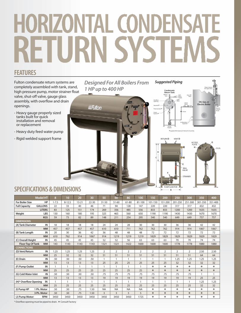
For Boiler Size HP 1-7.5 8-12.5 13-21 22-30 31-50 51-60 61-80 81-100 101-150 151-200 201-250 251-300 301-350 351-400Full Capacity GALLONS 22 33 40 46 71 94 128 147 220 220 317 317 432 432 LITERS 83 125 151 174 269 356 485 556 833 833 1200 1200 1635 1635Weight LBS 130 160 180 195 325 465 560 650 1190 1190 1430 1430 1670 1670 KGS 59 73 82 89 148 211 254 295 540 540 649 649 757 757DIMENSIONS
(A) Tank Diameter IN 18 18 18 18 24 24 28 30 30 30 36 36 42 42 MM 457 457 457 457 610 610 711 762 762 762 914 914 1067 1067(B) Tank Length IN 20 30 36 42 36 48 48 48 72 72 72 72 72 72 MM 610 762 914 1067 914 1219 1219 1219 1829 1829 1829 1829 1829 1829(C) Overall Height IN 45 45 45 45 52 52 56 63 63 63 70 70 74 74 Floor-Top Of Tank MM 143 1143 1143 1143 1321 1321 1422 1600 1600 1600 1778 1778 1880 1880CONNECTIONS
(D) Vent/Return IN 1.25 1.25 1.25 1.25 2 2 2 2 2 2 2 2 2.50 2.50 MM 25 32 32 32 51 51 51 51 51 51 51 51 64 64(E) Drain IN .50 .50 .50 .50 1 1 1 1 1 1 1.25 1.25 1.25 1.25 MM 13 13 13 13 25 25 25 25 25 25 32 32 32 32(F) Pump Outlet IN 1 1 1 1 1 1 1 1
MM 25 25 25 25 25 25 25 25
(G) Cold Water Inlet IN .50 .50 .50 .50 .75 .75 .75 .75 .75 .75 .75 .75 1 1 MM 13 13 13 13 19 19 19 19 19 19 19 19 25 25(H)* Overfl ow Opening IN 1 1 1 1 1 1 1 1 1 1 1 1 1.25 1.25 MM 25 25 25 25 25 25 25 25 25 25 25 25 32 32(I) Pump HP 1 Ph. Motor .50 .50 .75 1.50 NA NA NA NA
3 Ph. Motor .50 .50 .75 1.50 3 3 5 5
(J) Pump Motor: RPM 3450 3450 3450 3450 3450 3450 3450 1725
* Overfl ow opening must be piped to drain. Consult Factory
SPECIFICATIONS & DIMENSIONS
FEATURESFulton condensate return systems are completely assembled with tank, stand, high pressure pump, motor strainer fl oat valve, shut-off valve, gauge glass assembly, with overfl ow and drain openings.
• Heavy gauge properly sized tanks built for quick installation and removal or replacement
• Heavy duty feed water pump
• Rigid welded support frame
10 20 30 50 60 80 100 150
SMENSIONS
rainer fl oat ass
drain
p
RETURN D VENT D
C
A
B
PUMP & MOTOR
STRAINER
BALLVALVE
E
F
ACCESSPLATE
G
S.G.A.H
Designed For All Boilers From 1 HP up to 400 HP
Shut OffValve
CheckValves
Cold WaterSupply
SightGlass
Union
To BlowdownSeparator
Pump/Strainer
CondensateReturn Tank
Oil, Gas, orElectric Boiler
Water Columnand Sight Glass
ElectricControlPanel
Vent
OverflowOpening
Return
Aquastat*Thermometer*
*Supplied With Optional Preheat Kit Assembly
SteamInjector*
Suggested Piping
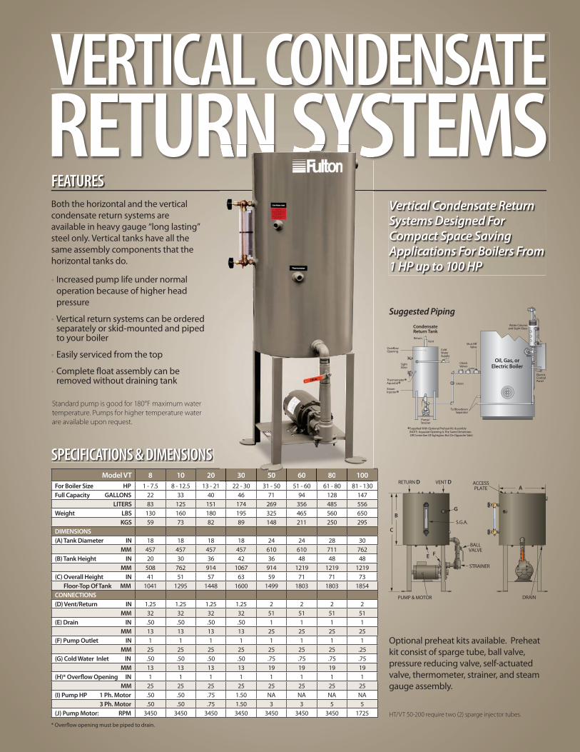
Model VT 8 10 20 30 50 60 80 100
For Boiler Size HP 1 - 7.5 8 - 12.5 13 - 21 22 - 30 31 - 50 51 - 60 61 - 80 81 - 130Full Capacity GALLONS 22 33 40 46 71 94 128 147 LITERS 83 125 151 174 269 356 485 556Weight LBS 130 160 180 195 325 465 560 650 KGS 59 73 82 89 148 211 250 295DIMENSIONS
(A) Tank Diameter IN 18 18 18 18 24 24 28 30 MM 457 457 457 457 610 610 711 762(B) Tank Height IN 20 30 36 42 36 48 48 48 MM 508 762 914 1067 914 1219 1219 1219(C) Overall Height IN 41 51 57 63 59 71 71 73 Floor-Top Of Tank MM 1041 1295 1448 1600 149 9 1803 1803 1854CONNECTIONS
(D) Vent/Return IN 1.25 1.25 1.25 1.25 2 2 2 2 MM 32 32 32 32 51 51 51 51(E) Drain IN .50 .50 .50 .50 1 1 1 1 MM 13 13 13 13 25 25 25 25(F) Pump Outlet IN 1 1 1 1 1 1 1 1 MM 25 25 25 25 25 25 25 .25(G) Cold Water Inlet IN .50 .50 .50 .50 .75 .75 .75 .75 MM 13 13 13 13 19 19 19 19(H)* Overfl ow Opening IN 1 1 1 1 1 1 1 1 MM 25 25 25 25 25 25 25 25(I) Pump HP 1 Ph. Motor .50 .50 .75 1.50 NA NA NA NA 3 Ph. Motor .50 .50 .75 1.50 3 3 5 5(J) Pump Motor: RPM 3450 3450 3450 3450 3450 3450 3450 1725
Optional preheat kits available. Preheat kit consist of sparge tube, ball valve, pressure reducing valve, self-actuated valve, thermometer, strainer, and steam gauge assembly.
HT/VT 50-200 require two (2) sparge injector tubes.
* Overfl ow opening must be piped to drain.
VERTICAL CONDENSATERETURN SYSTEMSFEATURESBoth the horizontal and the vertical condensate return systems are available in heavy gauge “long lasting” steel only. Vertical tanks have all the same assembly components that the horizontal tanks do.
• Increased pump life under normal operation because of higher head pressure
• Vertical return systems can be ordered separately or skid-mounted and piped to your boiler
• Easily serviced from the top
• Complete fl oat assembly can be removed without draining tank
C
B
E F
PUMP & MOTOR
STRAINER
G
S.G.A.
BALLVALVE
RETURN D VENT D ACCESSPLATE
DRAIN
A
Vertical Condensate ReturnSystems Designed For Compact Space Saving Applications For Boilers From 1 HP up to 100 HP
Standard pump is good for 180°F maximum water
temperature. Pumps for higher temperature water
are available upon request.
30 50 60 80 100
Vent
Cold WaterSupply
Return
CheckValves
SightGlass
Union
Pump/Strainer
CondensateReturn Tank
Water Columnand Sight Glass
ElectricControlPanel
Oil, Gas, orElectric Boiler
Shut OffValve
To BlowdownSeparator
OverflowOpening
Thermometer*Aquastat*Steam Injector*
*Supplied With Optional Preheat Kit Assembly (NOTE: Aquastat Opening Is The Same Dimension Off Centerline Of Sightglass But On Opposite Side)
SPECIFICATIONS & DIMENSIONS
Suggested Piping

Fulton Boiler Works, Inc.972 Centerville Road, Pulaski, NY 13142Call: (315) 298-5121 • Fax: (315) 298-6390
www.fulton.com
FBA12-bro-2011-0712
The heat transfer innovators.
Model F 10 20 30 50 75 100 150 200
For Boiler Size HP 1 - 10 11 - 20 21 - 30 31 - 50 51 - 75 76 - 100 101 - 150 151 - 200Max. Boiler Pressure PSI 150 150 150 150 150 150 150 150Capacity GALLONS 7.9 17.4 22 35.6 40.8 58.75 70.5 157 LITERS 30 66 83 135 154 222 267 594Weight LBS 110 190 200 255 295 415 450 585 KGS 50 86 91 116 134 188 204 260DIMENSIONS
(A) Height IN 32 34 34 40 44 44 50 63 MM 813 864 864 1016 1118 1118 1270 1600(B) Diameter IN 10.75 16 18 20 20 24 24 32 MM 254 406 457 508 508 610 610 813(C) Tank Height IN 20 20 20 26 30 30 36 48 MM 508 508 508 660 762 762 914 1219(D) Vent IN 3 3 3 3 4 4 4 5 MM 76 76 76 76 102 102 102 127(E) Drain IN 1.5 1.5 1.5 1.5 1.5 1.5 1.5 2 MM 38 38 38 38 38 38 38 51(F) Water Supply IN .75 1 1 1 1 1 1 1 MM 19 25 25 25 25 25 25 25(G) Outlet IN 3 3 3 3 3 3 3 3 MM 76 76 76 76 76 76 76 76(H) Inlet IN 1 1.25 1.25 1.50 2 2 2 2 MM 25 32 32 38 51 51 51 51(I) Thermometer IN .50 .50 .50 .50 .50 .50 .50 50 MM 13 13 13 13 13 13 13 13(J) Handhole IN 3 x 4 3 x 4 3 x 4 3 x 4 3 x 4 3 x 4 3 x 4 3 x 4 MM 76 x 102 76 x 102 76 x 102 76 x 102 76 x 102 76 x 102 76 x 102 76 x 102(K) Inlet Height IN 16 18 18 18 18 18 18 26 MM 406 457 457 457 457 457 457 660
FEATURESConstructed with the fi nest quality materials, all compact FultonBlow-Down Separators meet or exceed ASME Code and include special features to insure safe boiler blow-down. Fulton Blow-Down Separators also operate with minimum maintenance.
• Baffl e plate absorbs steam fl ash and pressure
• Steam is expelled safely through vent
• Water and sludge pass through drain to sewer
• 3” x 4” handhole for cleaning and inspection
• Welded to ASME Pressure Vessel Code
• Fast, easy hook-up to boiler
Fulton’s full line of heat transfer products includes:• Fuel-fi red vertical tubeless steam and hot water boilers
• New VMP 2000 vertical fl ue pipe design boilers
• Electric steam and hot water boilers
• Pulse combustion steam and hot water boilers
• Fuel-fi red and electric thermal fl uid heaters
Larger blow-down separatorsare available. Consult factory. Optional cooling kits available. Cooling kit consist of ball valve, strainer, thermometer and self-actuated valve.
See Fulton VMP Brochure for the 40, 50, 60, 80, 100, 130 and 150 HP Pipe Design and Vertical Boilers.
SPECIFICATIONS/DIMENSIONS/CONNECTIONS
MM 406 457
BD
G
IH
E
F
J
A
C
K