Fuel Cell Power Plant Initiative Preliminary Design of a Fixed-Base LFP/SOFC Power … · ·...
82
Fuel Cell Power Plant Initiative Final Report - Volume II Preliminary Design of a Fixed-Base LFP/SOFC Power System T. E. Dowdy, Project Manager Westinghouse Electric Corporation 4400 Alafaya Trail Orlando, FL 32826-2399 Prepared by: S. E. Veyo, Manager, SOFC Projects Westinghouse Science & Technology Center 1310 Beulah Road Pittsburgh, PA 15235-5098 November 1997 Prepared for the NASA Lewis Research Center Under Contract #NAS3-27022 https://ntrs.nasa.gov/search.jsp?R=19980002689 2018-05-27T04:38:39+00:00Z
Transcript of Fuel Cell Power Plant Initiative Preliminary Design of a Fixed-Base LFP/SOFC Power … · ·...

Fuel Cell Power Plant Initiative
Final Report - Volume II
Preliminary Design of a Fixed-Base LFP/SOFC Power System
T. E. Dowdy, Project Manager
Westinghouse Electric Corporation
4400 Alafaya Trail
Orlando, FL 32826-2399
Prepared by:
S. E. Veyo, Manager, SOFC Projects
Westinghouse Science & Technology Center1310 Beulah Road
Pittsburgh, PA 15235-5098
November 1997
Prepared for the NASALewis Research CenterUnder Contract #NAS3-27022
https://ntrs.nasa.gov/search.jsp?R=19980002689 2018-05-27T04:38:39+00:00Z

TABLE OF CONTENTS
I. INTRODUCTION .......................................................................................................................... I-I
2. POWER SYSTEM DESIGN ........................................................................................................ , .............. 2-1
2.1 SYSTEM DESCRIPTION ................................................................................................................................... 2-1
2.2 SYSTEM PERFORMANCE .............................................................................................................................. 2-5
2.2.1 Cell Basis ...................................................................................................................................................... 2-5
2.2.2 Cell Voltage-Current Density (V-J) Characteristics .................................................................................... 2-5
2.2.3 Power System Design Basis ....................................................................................................................... 2-11
2.2.4 PSOFC/GT System Design-Point Performance Estimates ........................................................................ 2-I2
2.2.5 Effect of LFP System Steam Requirements on Power System Performance ............................................... 2-12
2.2.6 Reference PSOFC/GT System Design-Point Specifications ...................................................................... 2-12
3. PRESSURIZED SOFC MODULE ........................................................................................................... 3-1
3.1 SOFC TECHNOLOGY BASIS ......................................................................................................................... 3-1
3.2 PSOFC SUBMODULE DESCRIPTION .......................................................................................................... 3-1
3.2.1 Fuel Cell Stack .............................................................................................................................................. 3-3
3.2.2 Fuel DistrtlTution System ............................................................................................................................. 3-6
3.2.3 Stack Reformers ............................................................................................................................................ 3-6
3.2.4 Air Supply System ..................................................................................................................................... 3-10
3.2.5 Canister ...................................................................................................................................................... 3-10
3.2.6 Internal Insulation Package ....................................................................................................... _............... 3-11
3.3 PSOFC MODULE DESCRIPTION ................................................................................................................ 3-11
3.3.1 Pressure Vessel ........................................................................................................................................... 3-11
3.3.2 Internal Submodule Supporting Structure ................................................................................................ 3-18
3.3.3 Air/T__haust Piping .................................................................................................................................... 3-18
3.3.4 Fuel Inlet Piping ........................................................................................................................................ 3-21
3.3.5 Purge Air System ....................................................................................................................................... 3-21
3.3.6 Electrical Interconnections ......................................................................................................................... 3-21
3.3.7 Generator Instrumentation ........................................................................................................................ 3-22
3.3.8 Module Insulation ...................................................................................................................................... 3-22
4. MAJOR SUBSYSTEMS ................................................................................................................... ............. 4-1
4.1 GAS TURBINE .................................................................................................................................................. 4-1
4.2 DEPLETED FUEL CONDENSER ................................................................................................................... 4-1
iii

4.2.1s ; aaons ................................................................................................................................................4-I
4.2.2 Condenser Type and Configuration ............................................................................................................. 4-4
4.3 THERMAL MANAGEMENT SYSTEM ......................................................................................................... 4-4
4.4 POWER CONDITIONING SYSTEM (PC.S) ................................................................................................... 4-5
4.5 INSTRUMENTATION AND CONTROL SYSTEM (I&C) ........................................................................... 4-7
5. DESIGN BASIS OF 3 MWE LOGISTIC FUEL PROCESSOR ............... _.................................................. 5-1
5.1 PROCESS DESIGN BASIS ................................................................................................................................ 5- I
5.I.1 Battery Limits .............................................................................................................................................. 5-1
5.1.2 Fuel ............................................................................................................................................................... 5-1
5.1.3 Fuel Cell Anode Feed - Wet Methane Rich Syn Gas .................................................................................... 5-2
5.1.4 Utilities: ........................................................................................................................................................ 5-2
5.1.5 Climatic Conditions: .................................................................................................................................... 5-3
5.1.6 Miscellaneous ............................................................................................................................................... 5-3
5.1.7 Codes and Standards .................................................................................................................................... 5-3
5.2 PROCF.SS DESCRIPTION ................................................................................................................................. 5-3
5.2.1 Introduction ................................................................................................................................................. 5-3
5.2.2 Desulfurization ............................................................................................................................................ 5-5
5.2.3 Reforming Section ........................................................................................................................................ 5-6
5.3DESCRIFrIVE START-UP PROCEDURE .......................................................................................................5-8
5.3.1UtilitiesRequired.........................................................................................................................................5-8
5.3.2Feedstocks/Startup Materials......................................................................................................................5-8
5.3.3Procedure......................................................................................_........................i.....................................5-8
5.4PRODUCTION & CONSUMPTION FIGURES ..............................................................................................5-I0
5.4.1Production:.................................................................................................................................................5-10
5.4.2 Consumption: ............................................................................................................................................. 5-10
5.4.3 Vessels ........................................................................................................................................................ 5-11
5.4.4 Misc ............................................................................................................................................................ 5-11
5.4.5 Heat Exchangers ........................................................................................................................................ 5-11
5.4.6 Pumps ........................................................................................................................................................ 5-1I
5.4.7 Compressors ............................................................................................................................................... 5-12
5.4.8 Reactors ...................................................................................................................................................... 5-I2
6. DISCUSSION .............................................................................................................................................. 6-1
7. CONCLUSIONS ....................................................................................................................................... 7-1
8. RECOMMENDATIONS .................................................................................................................................. 8-1
iv

9. NEW TECHNOLOGY .............................................................................................................. _1
9.1NON-PATENTABLE DISCOVERIES .............................................................................................................9-I
9.2PATENTABLE INVENTIONS ........................................................................................................................9-1
APPENDIX A ...................................................................................................................................................A-I
LIST OF FIGURES
Figure 2.1 -- LFP process flow diagram .............................................................................................................. 2-2
Figure 2.2 -- PSOFC/GT system process flow diagram ................................................................................... 2-3
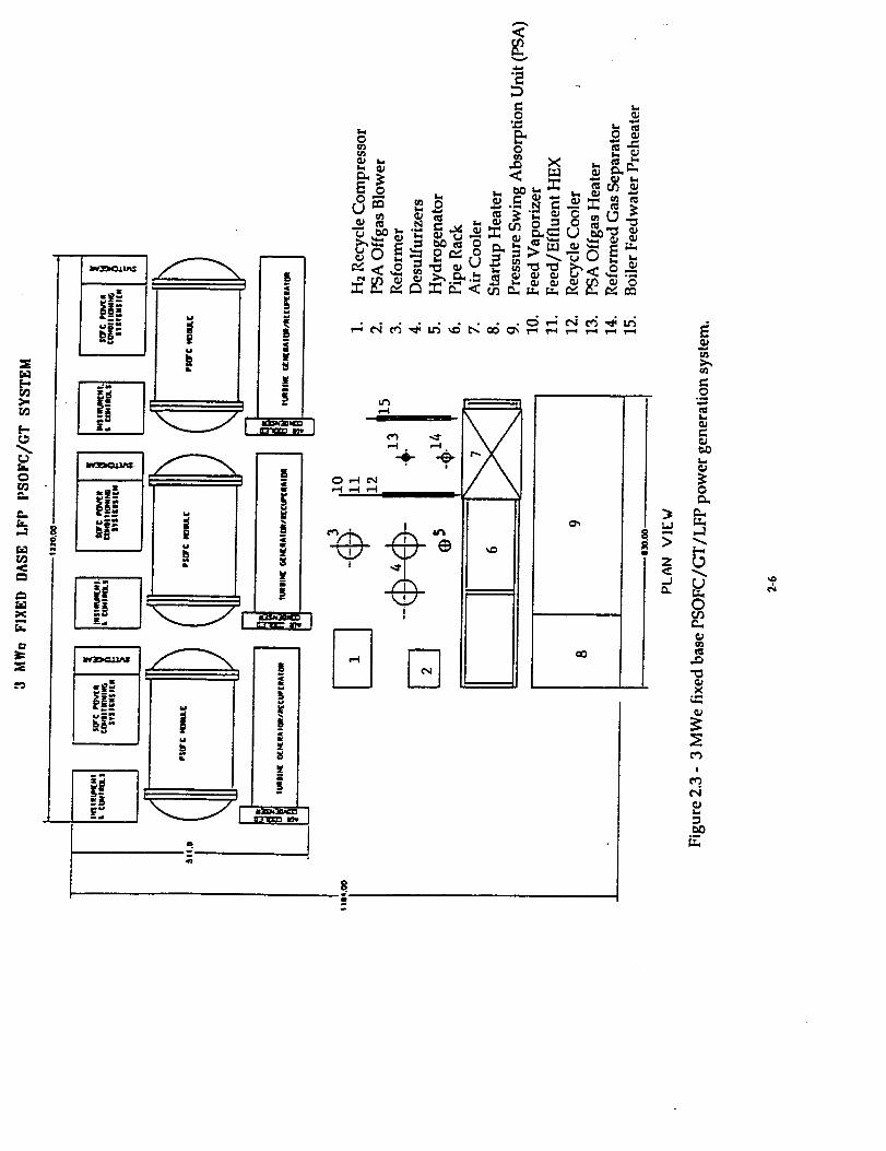
Figure 2.3 -- 3 MWe fixed base PSOFC/GT/LFP power generation system ................................................. 2-6
Figure 2_4 -- Westinghouse tubular AES cell ..................................................................................................... 2-7
Figure 2.5- Tubular AES cell with air injection tube ....................................................................................... 2-8
Figure 2.6 m Cell voltage-current characteristics ............................................................................................... 2-9
Figure 2.7 m Incremental effect of SOFC module pressure on cell voltage .................................................. 2-10
Figure 2.8 -- PSOFC/GT system performance estimates ................................................................................ 2-13
Figure 2.9 -- Effect of LFP steam conditions on PSOFC/GT system performance ..................................... 2-14
Figure 3.1 -- One MW LFP/SOFC power system .............................................................................................. 3-2
Figure 3.2 -- SOFC submodule ............................................................................................................................. 3-4
Figure 3.3 -- SOFC submodule cross-section ...................................................................................................... 3-5
Figure 3.4 _ SOFC generator stack. ..................................................................................................................... 3-7
Figure 3.5 -- SOFC generator stack cross-section ................................................. . ............................................ 3-8
Figure 3.6 -- Fuel Recirculation Loop .............................. i ................................................................................... 3-9
Figure 3.7-- SOFC submodule canister. [Dimensions in inches] .................................................................. 3-12
Figure 3.8 -- PSOFC pressure vessel [Dimensions in inches] ........................................................................ 3-13
Figure 3.9 _ PSOFC pressure vessel - cross-section. [Dimensions in inches] .............................................. 3-15
Figure 3.10 _ PSOFC pressure vessel - heads. [Dimensions in inches] ........................................................ 3-16
Figure 3.11 -- PSOFC pressure vessel - flanges. [Dimensions in inches] ...................................................... 3-17
Figure 3.12 _ PSOFC pressure vessel internal support structure ................................................................. 3-19
Figure 3.13 -- PSOFC pressure vessel with submodules installed ................................................................ 3-20
Figure 4.1 -- Depleted fuel condenser conceptual design .................................................................. .. ....... , .... 4-2
Figure 4.2 -- PCS schematic diagram. ................................................................................................................. 4-6
Figure 5.1 -- Logistic Fuel Processor Process Flow Diagram ........................................................................... 5-4
V

LIST OF TABLES
Table 2.1 - Power Generation System Design/Analysis Parameter Values .................................................. 2-11
Table 2.2 - PSOFC/GT System Design-Point Parameter Values and Performance Estimates ................... 2-15
Table 4.1 - Specifications for the Depleted Fuel Condenser .............................................................................. 4-3
vi

1. INTRODUCTION
This report documents the preliminary design for a military fixed-base power system of
3 MWe nominal capacity using Westinghouse's tubular Solid Oxide Fuel Cell [SOFC] and
Haldor Topsoe's logistic fuels processor [LFP]. The LFP provides to the fuel cell a methane rich
sulfur free fuel stream derived from either DF-2 diesel fuel, or JP-8 turbine fuel.
Fuel cells are electrochemical devices that directly convert the chemical energy
contained in fuels such as hydrogen, natural gas, or coal gas into electricity at high efficiency
with no intermediate heat engine or dynamo. The SOFC is distinguished from other fuel cell
types by its solid state ceramic structure and its high operating temperature, nominally 1000°C.
The SOFC pioneered by Westinghouse has a tubular geometry closed at one end. A power
generation stack is formed by aggregating many cells in an ordered array. The Westinghouse
stack design is distinguished from other fuel cell stacks by the complete absence of high
integrity seals between cell elements, cells, and between stack and manifolds. Further, the
reformer for natural gas [predominantly methane] and the stack are thermally and
hydraulically integrated with no requirement for process water.
The technical viability of combining the tubular SOFC and a logistic fuels processor was
demonstrated at 27 kWe scale in a test program sponsored by the Advanced Research Projects
Agency [ARPA] and carried out at the Southern California Edison's [SCE] Highgrove
generating station near San Bernardino, California in 1994/95. The LFP was a breadboard
design supplied by Haldor Topsoe, Inc. under subcontract to Westinghouse. The test program
was completely successful. The LFP fueled the SOFC for 766 hours on JP-8 and 1555 hours of
DF-2. In addition, the fuel cell operated for 3261 hours on pipeline natural gas. Over the 5582
hours of operation, the SOFC generated 118 MWH of electricity with no perceptible
degradation in performance. The LFP processed military specification JP-8 and DF-2 removing
the sulfur and reforming these liquid fuels to a methane rich gaseous fuel. Results of this
program are documented in a companion report titled "Final Report-Solid Oxide Fuel Cell/
Logistic Fuels Processor 27 kWe Power System".
1-1

The 27 kWe SOFC system tested at SCE used 576 tubular air electrode supported [AES]
cells of 185 cm sq active area [16 m_m diameter by 500 mm active length]. In February 1996
Westinghouse commenced the manufacture in a pilot manufacturing facility of commercial size
cells, (22 nun diameter by 1500 mm in active length yielding a cell active area of 834 cm sq.) A
natural gas fueled 100 kWe SOFC generation system, using 1152 of these commercial size
tubular SOFCs, is being sponsored by EDB/ELSAM [a consortium of Dutch and Danish
utilities] and will be dehvered in the fall of 1997 to NUON, the host utility in the Netherlands.
The EDB/ELSAM 100 kWe SOFC system operates at atmospheric pressure on natural gas fuel
and generates electricity at 47.5% efficiency. The maximum capacity of the system is however
approximately 160 kWe ac net. The SOFC stack is capable of producing 200 kWe dc.
Westinghouse has corroborated theoretical estimates of SOFC performance at pressures
up to 15 atm. in cell tests conducted at Ontario Hydro Technologies [OHT]. SOFC operation at
elevated pressure permits the synergistic integration of gas turbines [GT] with the pressurized
solid oxide fuel cell [PSOFC] in a combined cycle power plant where the PSOFC supplants the
GT combustor. Conceptual design studies sponsored by Westinghouse and a group of North
American utilities found that integer MWe natural gas fueled PSOFC/GT combined cycle
power plants could be configured to economically yield 63% electrical generation efficiency [net
ac/LHV]. Design studies considering packaging and transportation limitations have revealed
that an SOFC generator submodule containing approximately 2304 cells has weight and
dimensional parameters consistent with easy transport via truck. A pressure vessel to house
multiple SOFC submodules for pressurized operation is envisioned as a horizontally oriented
cylinder with a diameter consistent with truck transport. A one MWe class natural gas fueled
system, for example, would use two SOFC generator submodules of 500 kWe nominal capacity
at elevated pressure contained within a single pressure vessel operating in tandem with a GT
engine generator set of nominally 300 kWe capacity. Each 500 kWe SOFC submodule uses two
1152 cell stacks siamesed in a single canister. Each 1152 cell stack is virtually identical with the
stack in the 100 kWe atmospheric pressure SOFC generator module now in fabrication.
In order to achieve a nominal power plant capacity of 3 MWe, six PSOFC submodules
will be required. These six could be arranged as one six-pack of PSOFCs and one GT, two
three-packs of SOFC and one or two GTs, or as three twin-packs of SOFC and three GTs. The
basis for the design for a 3 MWe fixed-base military power plant is based upon this latter
1-2

configuration, three PSOFC twin-packs, each coupled with a GT. This arrangement has several
advantages. The first is enhanced transportability, since the twin pack PSOFC module
elements are truck transportable. Second, the arrangement yields enhanced reliability since a
failure of any one PSOFC submodule, or any one GT, would only place one third of the power
plant out of service. Third, this arrangement provides greater flexibility for variable load
dispatch since the overall power ranges from the minimum power for a single twin-pack to the
maximum power for the sum of all twin-packs. Fourth, since the GT can be fueled with liquid
diesel or turbine fuel during start-up, a cold start in isolation from a conventional electric grid
is feasible. Lastly, given new Department of Defense directives to maximize the use of
technology from within the civilian sector, perhaps the greatest advantage to the three twin-
pack configuration is that the single twin-pack plus single GT configuration yielding nominally
one MWe is that which Westinghouse, its major subcontractors, and its major utility supporters
believe will be a unit with great plurality in the civilian marketplace.
The logistics fuel processor for the 3 MWe SOFC/LFP fixed-base military power system
is based directly on the Haldor Topsoe, Inc. supplied brassboard tested with the 27 kWe SOFC
at SCE. However, the 3 MWe LFP will use water recovered from the SOFC spent anode gas for
logistic fuels processing, making the system water neutral during normal operation, rather
than stored process water as was done for the 27 kWe unit. Further, the hydrogen required for
the hydrodesulfurization of the logistic fuels will be recovered from the LFP process stream
and recycled, rather than using stored hydrogen as was done for the 27 kWe demonstration.
The PSOFC/LFP enables a new class of highly efficient, multi-fueled power systems to
be configured for both civilian and military fixed-base use, thereby contributing directly to a
reduction in the consumption of fossil fuels and a concomitant reduction in the evolution of
CO2, the greenhouse gas, with virtually no emission of NOx or SOx.
1-3

2. POWER SYSTEM DESIGN
2.1 SYSTEM DESCRIPTION
The power system design is based on the integration of a pressurized solid oxide
PSOFC generator module with a GT. The PSOFC module operates on fuel gas provided by the
LFP and the electrochemically-unused part of that fuel is then reacted in the GT combustor.
Supplemental fuel is needed at the turbine combustor to provide the design point gas
temperature to the turbine inlet, and that fuel is liquid DF-2 or JP-8. The power generating
portion of the system is composed of the PSOFC module, the GT engine/generator, and a heat
recovery system (HRS). The function of the HRS is to supply steam to the LFP and to preheat
air for the PSOFC module. The PSOFC/GT system is designed to deliver I MW net ac power.
Three of these units would be teamed with the LFP to produce the required 3 MW
PSOFC/GT/LFP power system.
Figure 2.1, a process flow diagram for the LFP, illustrates the basic integration of the
LFP with the PSOFC/GT power system. The LFP is discussed in detail in Section 5.0. As the
figure shows, there are three points at which the LFP interfaces with the PSOFC/GT system.
At two points, LFP fuel gas and condensate are supplied to the PSOFC/GT system, and at the
third interface point, the PSOFC/GT system delivers steam at the flow rate, pressure, and
temperature required by the LFP. It should be noted that the steam generation rate exceeds the
condensate flow rate. This implies that other sources of water must be found within the
system for it to achieve water self-sufficiency. The principal additional water source is the
depleted-fuel stream that emanates from the SOFC module. Another is the gaseous fuel stream
from the LFP. The latter stream contains over 20% water vapor, which can be cooled to
condense a portion of that vapor.
Figure 2.2, the process flow diagram for the PSOFC/GT system, shows the three
LFP interface points that were identified above. The fuel-gas stream arriving from the LFP
system can be found in the upper left-hand comer of the diagram, and the LFP condensate
stream merges with water from other sources at the power system condensate tank; steam to
be returned to the LFP system is provided by the HRS.
2-1

A
C
D
E
G
STREAM NO. L _'
DESCRIPTION RAV DIESEL
. _ 31,999 1
_.Ot6
28.013
2B,Oll
44,010
39,948
16.043
N [Iki_I,_.N
C_BON MONOXII:I:
CARBON DIOXIDE
ARGON
M_TMANE
e3.o¢
3
PSA
4 5
C_S TEl _ FRONREF'D_MI_R RID'I_4{R
41_.. 7 30.76
0,86 L09
t5,_3 18.9+
• 39.04
,,49"2[
too
DIE,TEL
WAER
TOT.W.
AVG. IdOL tcr.
PRESSURE. B_'_ ABSTIB4P[P,A_ DE(;. C
R-101 .R-IOR14YDROGENATOR DESULFUeZER
)..2:
>..21
R-I03 P-101A/BR_ORMER FEED PUMPS
K-,103 E-101 E-I02EJECTOR RECYCE F_ED/EFFLUENT
COOLER _'XO-'ANGER
I"--I,
E-103PI_3CESS
C¢_SHEATE_
GA_
0.41
K-l(MYORCNRECYC
COMPR_
+"1E-
R-101
I
IT
t
R"
V..R-;O;_
I
R-103
I
K-I03
E-I01
K-102
Z
_av DIESEL:
C_LCLI.ATION I Z75984
llD-OtO / _ S,/'30/'_lms / 'r._,_.
A mr._m
[_ IOP_IlMIK, ¢
}--'I _o. _
I3 5
Figure :

9 10
7
K-101
F
TIE: ]_:SC_P'_ON
l 6
!.1 - LFP process flow diagram.
_VN C)_CX_
Z_'.,N_ .c e.,*,,_ _ _ HALDOR TOPSOE. INC.
iPll_l:T_._ _ O_,marRmEz,,m_m._' 3 NY _F'Cme_e me oB'_D me
IDI_)W al;
.mar. ,,z,c ++m,_a,s or IW._TION AND R_=Oltl4l]qO,14S Or+O,Imm_ N_' +U. _
o_ 65036-F'D-OIO PI"
2-2

z_.
C_
C_
E
!
Lm_4

The fuel gas delivered by the LFP is at a moderately high temperature, 459°C, and its
pressure, 2 bar (abs), is below the power system operating pressure of 3.8 atm. To facilitate fuel
compression, the gas is cooled at the fuel cooler, and its water content is reduced in the process. The
heat removed is presently assumed to be rejected to the ambient air, although it is conceivable that a
system use could be found for that heat, and the condensate is pumped to the condensate tank for
power system water-balance purposes. The fuel-gas temperature at the cooler exit is approximately
50°C. The dried/cooled fuel-gas, after compression, is delivered to the PSOFC module.
The module is also supplied with preheated air. The required air temperature at the
module inlet will typically be in the vicinity of 500°C. The air is heated in part by work of
compression at the GT compressor, and by the recuperation of turbine exhaust heat at the HRS.
The PSOFC module produces dc electric power. As Figure 2.2 indicates, this power
can be converted to ac form by the power conditioning system.
Two gas streams emerge from the PSOFC module. One is composed of depleted
SOFC fuel (SOFC anode exhaust), and other is depleted air (SOFC cathode exhaust). The
power system design incorporates this two-stream feature to ease the problem of recovering
water from the SOFC exhaust in order for the system to be water neutral. Implementing this
feature requires that the SOFC module be designed mechanically to keep the streams separated
within the module, and to let them pass separated from the module. The depleted-fuel stream
flow rate is small, but it has the high water vapor content due to the electrochemical fuel
oxidation process. The water needed to complete the power system water balance is removed
at the depleted-fuel condenser, and the cooled, dried, depleted-fuel stream is supplied to the
gas turbine combustor. The heat withdrawn from the depleted-fuel stream at the condenser is
significant, and if it were integrated with the heat recovery system to assist in the process of
generating steam for the LFP, then system efficiency could be improved relative to the present
analysis where an ambient air cooled condenser is considered for the sake of system simplicity.
The depleted-air stream serves as the oxidant for the GT combustor. The oxygen contained in
the stream is sufficient to combust the hydrogen and carbon monoxide in the depleted fuel,
and the liquid diesel. The combustor exhaust is at the temperature required at the gas turbine
inlet. The shaft work delivered by the turbine drives the compressor section; surplus work
goes to the generation of additional ac power at the turbine generator.
2-4

The hot turbine exhaust will typically be at temperatures in the range of 600°C.
Sensible heat in this stream is recovered at the HRS to heat air and to generate LFP steam.
Note that the steam generator superheater section is placed ahead of the recuperator to provide
the steam temperature, 480°C, required by the LFP. In general, the recuperator effectiveness
should be as large as possible to maximize the system operating efficiency, but it can be set no
higher than the value that will still provide for an acceptable pinch temperature differential at
the HRS evaporator section. In this design study, the evaporator pinch was required to be no
smaller than 8.3°C. Supplying heat for steam generation from another source, such as the
depleted-fuel condenser, or reducing the steam design pressure and/or temperature, would
allow the recuperator to be designed with a higher effectiveness, and this would provide for
increased power system efficiency.
A plan view of the 3 MWe fixed-base PSOFC/GT/LFP power generation system is
provided in Figure 2.3.
2.2 SYSTEM PERFORMANCE
2.2.1 Cell Basis
The design study and the power generation system performance estimates were based
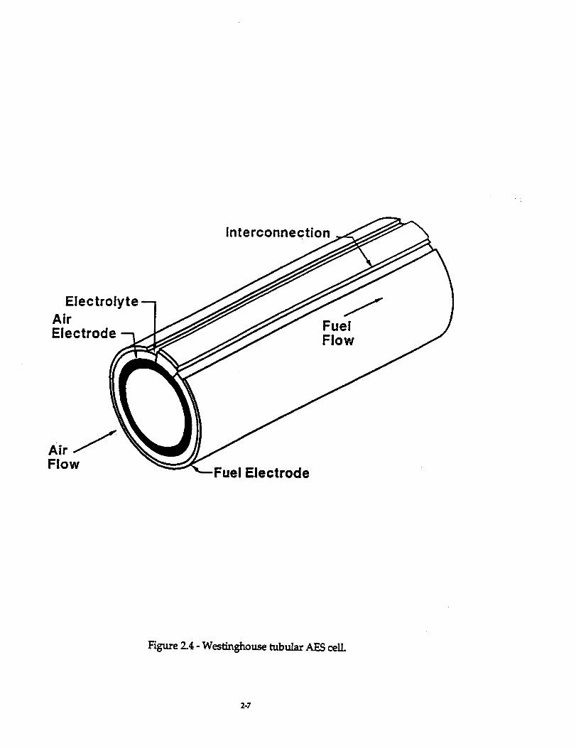
upon the air-electrode-supported Westinghouse tubular SOFC design depicted in Figure 2.4.
The cell has four parts - the air electrode (cathode), fuel electrode (anode), the electrolyte, and
the interconnection. The cell diameter is 22 mm and its active length is 1500 mm. Fuel gas
contacts the fuel electrode, and air is supplied to the air electrode through the air injection tube
that is shown in Figure 2.5. The pressurized SOFC module contains 4608 such cells divided
evenly between two SOFC submodules. Additional pressurized module design detail is
provided in Section 3.
2.2.2 Cell Voltage-Current Density (V-J) Characteristics
Cell V-J estimates for this study were developed analytically as a function of SOFC
fuel utilization. These estimates, applying to atmospheric-pressure operation, are provided in
Figure 2.6. Cell voltage estimates for the regions between curves were obtained by linear
interpolation, and the incremental effect of elevated pressure on cell voltage is obtained using
the Nernst Equation. The effect of pressure on cell voltage is presented in Figure 2.7.
2-5
o
<
interconnecti,
ElectrolyteAirElectrode
FuelFlow
FlowFuel Electrode
Figure 2.4 - Westinghouse tubular AES celL
2-7

i
Air
GaseousFuel
Figure 2.5 - Tubular AES cell with air injection tube.
2-8

Pressure: 1 atm0.80
m
o
I
(Ifm
o>
(b
0.75
0.70
0.65
0.60
0.55
0.50
0.45
0.40
: 80
: 85
FUel Utilizatibn, %
0 100 200 300 400 500
Cell Current Density - mA/cm 2
600 700
ARPA22
Figure 2.6 - Cell voltage-current characteristics.
2-9

0.10
O9m
0>
!
c-(DECD0c-
OD
o_m
0>
CDf.D
0.08
0.06
0.04
0.02
0.00
0 5 10 15 20 25 30
Operating Pressure - Atm (abs)
35
VJ-2
Figure 2.7 - Incremental effect of SOFC module pressure on cell voltage.
2-10

Tests being performed jointly by Westinghouse and Ontario Hydro Technologies confirm the
validity of this relationship.
2.2.3 Power System Design Basis
Values of key design parameters are identified in Table 2.1.
Table 2.1 - Power Generation System Design/Analysis Parameter Values
2-11

2.2.4 PSOFC/GT System Design-Point Performance Estimates
PSOFC/GT system design-point performance estimates are presented in Figure 2.8.
The power parameter is a net value for each PSOFC/GT system defined as the sum of the gross
ac power outputs from the SOFC power conditioning system and the turbine generator, less
the electric power required to drive the fuel compressor and the feed/condensate pumps. It
does not account for LFP system parasitics 1. With the SOFC module configuration fixed and
including two submodules, each submodule consisting of 2304 cells, each point on the curve
applies to a different SOFC operating point - the low-power points to low cell current densities,
and the high-power points to high current densities. The GT design, however, is not constant
along the curve. For the present analysis, the turbine inlet temperature and pressure ratio are
fixed, but the compressor air flow rate varies from point to point as determined by the SOFC
air flow requirement, and there is no system design feature to facilitate the bypassing of excess
air around the SOFC module. Given a power output requirement of 3 MW total, or I MW net
ac per PSOFC/GT system, Figure 2.8 enables the specification of GT equipment for integration
with the fixed PSOFC module.
2.2.5 Effect of LFP System Steam Requirements on Power System Performance
Due to their influence on recuperator sizing, the pressure and temperature of the
steam to be generated by the power system and delivered to the LFP system affect power
system efficiency. The sensitivity of the design-point efficiency estimates to variations in steam
conditions is indicated in Figure 2.9. The reference curve is from Figure 2.8. These estimates
indicate that the effect of steam conditions on power system performance is not insignificant,
and they are provided here for reference use during subsequent power system and LFP design
projects.
2.2.6 Reference PSOFC/GT System Design-Point Specifications
Based upon the analysis discussed in the preceding section, a reference PSOFC/GT
system design has been selected. Values of key design parameters for this design are
1 LFP parasitic power is estimated at 33 kW (Section 5.42), one percent of plant output.
2-12

6O
PSOFC Module - One, Housing Two SubmodulesGas Turbine - One 200 kW-Class
Gas Turbine Inlet Temperature - 970CCompressor Pressure Ratio - 3.8:1SOFC Fuel - LFP
GT Fuel - SOFC Depleted Fuel + Diesel FuelSOFC Fuel Utilization - 90%SOFC Stoichs - 3.5
o_!
>
_.J
o_
03
O_Zv
c_
°u
C)°m
LU
03EL
OEL
58
56
54-
52
5O
0.6 0.8 1.0 1.2 1.4
Power Output - MW Net ac
1.6
ARPA20
Figure 2.8 - PSOFC/GT system performance estimates.
2-13

6O
PSOFC Module - One, Housing Two SubmodulesGas Turbine - One 200 kWoClassGas Turbine Inlet Temperature - gTOC
Compressor Pressure Ratio - 3.8:1SOFC Fuel - LFPGT Fuel oSOFC Depleted Fuel * Diesel FuelSOFC Fuel Utilization - 90%SOFC Stoichs - 3.5
o_I
>-1-
d_
E3
0_Zv
¢-
C_
LU
c-
EL
G)
OEL
58 ......................................................................................................................
D_.
C "'_': ".
B "° _ :
A _""L'_
s4........................i........ .........i...............................................
............ LFP Steam P & T ............................................................................A - 35 bar {abs), 480C - (l:_eference Case)iB - 25 bar _abs), 480CC - 35 bar ._abs), 350C , ,
52 ........ l_-2_;B_ii"._=iB_);3s_...........................................................................
....................... :. ...................... ... ...................... ._....................... : .......................
5O
0.6 0.8 1.0 1.2 1.4 1.6
Power Output MW Net ac A.P_I
Figure 2.9 - Effect of LFP steam conditions on PSOFC/GT system performance
2-14

summarized in Table 2.2, and estimates of design-point performance parameters are also
presented.
Table 2.2 - PSOFC/GT System Design-Point Parameter Values and Performance Estimates
Parameter.............................................................. i. .................................
No.pressurizedSOFCmodules 1.............................................................. i. .................................
No. submoduleslmodule 2.............................................................. • .................................
No.cells/subrnodule 2304.............................................................. • .................................
Compressorair flow 5734kg/h
Compressorpressureratio 3.8:1...............................................................................................
Turbine inlettemperature 970C
"iigcl,;;;;t;;;_';_';_'e'_ ......................................... !'i(F2 ..............................................................................
Cellcurrentdensity ........... _"3"2"0"mNcm_.......................
..............................................................Cellcurrent _"2"7"5"am; .........................
..............................................................Gel'voltage [ "6"6"8"_1_/"..........................
i_iS/_';_;m;_ul;'t;_;n';_,;l't;,_;.................................. ."'ih'(' ............................
i_iSi__oc_,;I;'te_i'nl;cu;r;;i..................................... /'ffL;;n;; .........................
"iid_'Gi_',zi;i;_ ............................................. .r"_o'4.............................
-_F_s]oic_s .................................................. r-3-.g..............................
•i;iSi_'_r;;; ;_c'pow';_............................................ ."'0"._i(5_;v"........................
"Ci'-_s"turI;ine "gros s ;c'power ....................................... i "0"._.;_gMW"........................
•"P'o;,er's);;i_n6"a_'_ow;;....................................... _'"1"._'6_v".........................
Diesel supplyto LFP , 122.9 kg/h...............................................................................................
Dieselsupplyto gas turbinecombustor , 29.9 kg/h
Efficiency(net ac./diesel LHV) , 54.5..............................................................................................
Exhaustflow , 5888kg/h............................................................. i .................................
Exhaust temperature , 206C
Note: Three PSOFC/GT systems required.
*The performance estimates presented in this table are based on the assumption that heat from
the depleted-fuel condenser is integrated with the HRS to reduce the amount of heat that mustbe recovered from the turbine exhaust for the generation of LFP steam. This enables the use at
the HRS of a large-effectiveness recuperator, and it results in maximum system efficiency.
However, the equipment design and arrangement concept discussed in this report does not
reflect this heat integration, but it should be included in future development work on the
power system concept. If the high-grade heat from the depleted-fuel condenser is notintegrated with the HRS, the required recuperator effectiveness is 68.7% (vs. 81.6% with heat
integration), and the power system efficiency slips to 51.2% (vs. 54.5%).
2-15

3. PRESSURIZED SOFC MODULE
3.1 SOFC TECHNOLOGY BASIS
Much of the PSOFC Power Generation system design philosophy and implementation
are influenced by technology derived from two sources: the current 100 kW SOFC generator
operating at atmospheric pressure and the Pressurized Bundle Test Article designed to operate
up to 10 arm.
The proposed configuration of the PSOFC/GT system is depicted in Figure 3.1. It
illustrates one pressurized SOFC Module coupled to a conventional gas turbine
engine/generator. Electric power is generated by both the fuel cell and the rotary induction
generator connected to the gas turbine.
These components can be mounted on individually transportable skids to form a
modular system.
A key advantage of this concept is a remarkably simple power plant architecture
utilizing advanced SOFC fuel cell modules coupled to a commercial gas turbine and induction
generator.
3.2 PSOFC SUBMODULE DESCRIPTION
The generator submodule design philosophy is an extrapolation of the existing 100 kW
SOFC generator configuration with the exception that two stacks are fueled from a common
ejector/pre-reformer section. The entire assembly is subsequently installed into a common
canister lined with high performance thermal insulation. This configuration greatly simplifies
assembly of internal components by utilizing common parts and a modular, reusable
insulation system.
Each stack contains 1152, 1500 mm active length tubular fuel cells, each generating over
200 watts, arranged in 12 bundle rows. The cells are arranged in three parallel paths yielding a
stack terminal voltage of approximately 250 volts.
3-1

e_
Or,_OZ
_0
o
0
0I
c_

The submodule's configuration is depicted in Figure 3.2. As shown, each includes two
internal fuel cell stacks, a common fuel pre-reformer with integral fuel distribution manifold
and recirculation plenum, dc power leads and internal insulation.
Both stacks are fed from a common fuel supply system including a recirculation loop,
an ejector, a pre-reformer and a fuel manifold. Because of the size of the stacks, there are two
recirculation plenums and two ejectors feeding a common pre-reformer. The recirculation
plenum is used to mix the depleted fuel extracted from the stack with the fresh incoming fuel
injected through a nozzle. The mixture is then directed through an ejector into a pre-reformer
chamber where higher hydrocarbons are reformed to prevent carbon deposition in
the stack reformers where full reformation of methane occurs. From the pre-reformer exit, the
fuel mixture is distributed to both stacks through a series of bottom manifolds. Figure 3.3
shows the centrally located pre-reformer and the fuel manifolds feeding both stacks.
Process air is introduced into the submodule through two lower inlet nozzles located on
opposite sides of a bottom plenum, as shown in Figure 3.2. The same air is used to actively
cool the canister through a series of parallel vertical ducts surrounding the outer shell and
terminating in a large upper plenum. From this area, process air is distributed to an array of
smaller air plenums through intermediate bellows type expansion ducts. Each air plenum
supplies air to 144 adjacent cells through ceramic air feed tubes. Air flows from the air plenum
into the air feed tubes, which convey the oxidant to the lower, closed-end of each fuel cell.
3.2.1 Fuel Cell Stack
The tubular SOFC (see Figure 2.4) features a porous air electrode made of doped
lanthanum manganite, a ceramic. An axial strip of air electrode is covered by a thin, dense
layer of doped lanthanum chromite. This strip, termed the cell interconnection, serves as the
electric contact between the cell cathode (air electrode) and the anode (fuel electrode) of an
adjacent cell or a power contact. A gas-tight electrolyte layer of yttria-stabi]iTed zirconia covers
the exposed air electrode, overlapping slightly the interconnection. A top layer, the fuel
electrode, is a nickel-zirconia cermet and covers the electrolyte surface except in the vicinity of
the interconnection.
3-3

Cell Stacks
Power Leads
94.58
\Air Ducting forCanister Cooling
Air Inlets
Figure 3.2 _ SOFC submodule.
3-4

Power Leads
Recirculation Loop
Canister
Air Inlets
Figure 3.3 _ SOFC submodule cross-section.
3-5

To construct an SOFC generator, individual cells are bundled into an array of
electrically connected fuel cells, forming a monolithic structure that constitutes the basic
generator stack, as shown in Figure 3.4. The fuel cell stack consists of 48 bundles, each a 3x8
cell array. Each cell has an active (interconnection) length of 1500 ram. The cells are electrically
interconnected in three parallel paths, each with 384 cells connected in series.
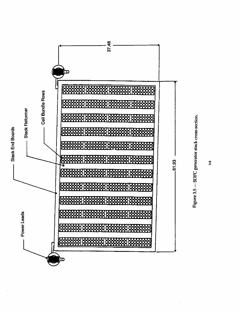
The stack cross section, as shown in Figure 3.5, has 12 bundle rows, separated by
electrically insulating stack reformers. Each bundle row consists of 96 cells (three parallel paths
of 32 series-connected cells)
These bundle rows are series-connected in a serpentine configuration and terminate at
power take-offs which transfer current to the two power leads. The power leads are air cooled
to withstand the high temperature environment surrounding the cell stack. Each fuel cell stack
is supported by a lifting tray which is also utilized during stack assembly.
3.2.2 Fuel Distribution System
The Fuel Distribution System, Figure 3.6, includes a dual fuel nozzle housing, a
recirculation plenum system, ejectors, pre-reformer and an array of tubular manifolds
connected to the stack reformers.
Fresh fuel is injected through a nozzle into each ejector which entrains depleted gas
extracted from the upper zone of the fuel cell stack. This fuel mixture is directed to a pre-
reforming section where higher hydrocarbon reformation occurs within a catalytic bed.
The fuel stream then exits the pre-reformer and is manifolded through a piping
network connected to horizontal manifolds installed at the base of the fuel cell stack. These
manifolds are coupled at the periphery of the stack by a quick connect flange assembly.
Each manifold directs the fuel into the stack reformers where nearly total reformation
occurs. Reformed fuel is fed to the base of the stack to the exterior of the tubular fuel ceils.
3.2.3 Stack Reformers
The stack reformers contain catalytically active material and accomplish approximately
85 to 90% of the fuel reformation, depending on the generator's operating point. Heat is
radiated from the adjacent cell bundle region to supply the energy required for the
endothermic reformation reaction.
3-6

Stack Reformer
Cell Bundle Rows
Power Leads
81.81
37.48
61.93
Figure 3.4 _ SOFC generator stack.
3= 7 • •
0
n-
o or)rn
"ocLu
cJ
O9
3:0cc
_m"0e-
ra
G)0
,q-
O9
0
U
0
0
_J
(3
Iu!.
°,..i

0
I
N •N_-_-
O-QzE_ •

3.2.4 Air Supply System
Process air is introduced at the top of the generator submodule into an array of air
plenums. Air flows from the air plenums into the air feed tubes, which are coaxial with the fuel
cells and convey the air to the bottom of the cell. The air subsequently flows upward through
an annulus between the feed tube and the cell inner surface. Spent air exits from the open end
of the cells and enters the combustion zone.
A portion of the spent fuel exiting the electrochemically active portion of the SOFC
stack is recirculated and mixed with fresh fuel via ejectors as previously described. The portion
not recirculated is extracted and directed to an external condenser for water removal. Very
little spent fuel is passed to the combustion zone for an SOFC stack intended for operation on
logistic fuels. In the Westinghouse seal-less stack design, a more complete separation between
combustion zone and spent fuel plenum is accomplished using a thicker [longer leakage path]
upper-most baffle board, and appropriate pressure balance. In the combustion zone, any spent
fuel entering is consumed.
Because the air feed tubes cross the combustion zone in a manner similar to a gas-to-air
heat exchanger, incoming air is heated by the exhaust gas exiting the cell stack. The exhaust
gas is directed to an upper dome prior to being manifolded to an external common exhaust
duct.
High pressure exhaust gas is collected from both submodules and is conveyed to the
gas turbine through insulated piping. The turbine drives the compressor for compressing air
that is delivered to the fuel cells.
3.2.5 Canister
Preheated, compressed air is introduced at the base of each submodule canister through
two nozzles leadingtoa lower plenum. From thisarea,airisdivertedto a number of
peripheral cooling ducts integral with the vertical wall of the inner canister.
Air exiting the ducts is further collected into an upper peripheral manifold which
distributes an equal amount of flow to each air plenum.
The inner canister is a stainless steel 304 L container, air cooled with process air, and
internally insulated with a layer of high performance ceramic insulation installed in the cavity
surrounding the fuel cell stacks.
3-10

Geometric configuration and overall dimensions of the submodule canister are shown
in Figure 3.7.
3.2.6 Internal Insulation Package
The internal insulation package consists of a number of highly efficient thermal
insulation modules interlocked to form an effective thermal barrier system between the cell
stack operating at 1000_C [1800°F] and the inner canister cooled with 650gC [1200°F]
temperature air.
The insulation modules are constructed from high purity alumina ceramic material
which has a microporous structure. A layer of low density fiber material is bonded to one face
to form a compliant composite capable of accommodating cyclic thermal differential expansion
between the ceramic cell stack and the steel canister while offering effective bypass gas sealing
and outstanding thermal insulation.
3.3 PSOFC MODULE DESCRIPTION
The pressurized SOFC module includes two submodules connected electrically in series
to the module terminals.
The submodules are installed within a horizontal pressure vessel containing a
supporting structure designed to provide easy access to the internals and easy assembling and
replacement of the submodules without interference with the installed internal components.
3.3.1 Pressure Vessel
The pressure vessel, as shown in Figure 3.8, is a horizontal cylindrical shell with two
flanged side covers and it is supported by two saddles anchored to the shipping container
structural frame.
Pressure bearing components are required to meet construction codes such as the
American Society of Mechanical Engineers (ASME) B31.1 piping code or the ASME Boiler and
Pressure Vessel (BPV) Code. The allowable stresses for materials currently approved for
construction under the rules of Sect. VIII, Div. 1 of the ASME BPV Code are provided in
Various Code Cases or in Sect. II, Part D.
3-11

c_

w
..0
aO
00
0
i--
m
,,.,=1
O
0
o.L.b,I 0
We,,-.
W
00
"ql"--'"_ W,, _ ___
!
00
°
,.C
°_
°_
0
Ie_
_O

The design of the components is in compliance with the ASME BPV Code, Section VIII,
Div. 1, 1995 Edition. The cylindrical shell material is SA-516, Grade 70 carbon steel which
provides a tensile strength range from 70,000 to 90,000 psi. The cylindrical shell thickness is
determined by the tangential stress due to the design pressure. Since the maximum
longitudinal stress (PR/2t) is only half of the maximum tangential stress, one-half the shell
thickness is available for the longitudinal bending stress due to weight at the midspan or in the
plane of the saddles, assuming the vessel to behave as its own carrying beam
As shown in Figure 3.9, the pressure vessel is supported by two saddles including four
legs and stiffener plates. The saddles are welded to the outer shell of the vessel with a 120
degree contact angle, and they could be anchored to a concrete slab in the field. The saddle
reactions are highly concentrated and induce high localized stresses in the shell which are
within the allowable stress conditions specified by the ASME Code.
The side covers are ellipsoidal heads, cold formed from the same material as the
pressure vessel, and welded to the mating flanges as shown in Figure 3.10.
To decrease the cost of the heads, a special design from the Hackney & Brighton
Company has been selected. This highly efficient design, known as the 80-10" style, meets all
ASME BPV Code requirements and it permits significantly higher pressures than other
standard configurations selected for the same service because of its geometrically stronger
configuration. The 80-10 ®head typical dimensions include a dish radius that equals 80% of the
head diameter and an inside corner radius which is equal to 10% of the head diameter. These
dimensions compare to 100% and 6% respectively for standard ASME Flanged and Dished
(F&D) heads. For the same internal pressure the 80-10 ®head is only 66% of the thickness of the
ASME F&D head, therefore material cost is minimized. Typical cost of a 80-10 ®head with an
outer diameter of 150 inches and a thickness of 1 inch, is approximately $4600 (10/96 cost).
The four side flanges shown in Figure 3.11, have an outer diameter of 166 inches and a
length through the hub of 11.5 inches and are forged from SA-105 carbon steel material. Sixty
2.75 inch diameter radial holes are drilled through the face of the flange for the bolts. The
overall weight of each flange is approximately 8000 lb. The cost of this component is
significant being a large diameter forged material, and is approximately $33,000 (11/96 cost).
3-14

0
8
0
.J
.qC
0
0
L_.__
0
0
m
J I
, jm
I
I0
I
ID
I
IJ
I
i
Ig
!t
Ii
I
I
ie
I0
I
iG
!
00
• _l
1
o
°
-- O
o
0
0
00
i
0
II
II
t
i
00
N
...q
@J
d°_
!
0
I_h

.q=
O.d:=
-qC 0
C:J ,qC o_
Q. r,._ !_Z.,.J_ ..
.,..J
wI.--
o
D
0
o o
o_ w
0
0
_r,J
m
o
0,.w
..,,J
IdJ
_J
°_
oU3
I
U_U3
L,
U_
0
Ic_v-q

w'_¢7'J
°_
0 0
I
I
0 0
°
0o
L..
00
L
0
\\\\\\\\\"
0
.----,--ID.
00
i
,9C
Z
I-;.-
._Jm
w
W
W
1 t0
L,b._ e.,.)
W
Q...
00
t
t
0
_w
!
0
I
o_
,h

The left side flanged cover includes three penetrations, one upper exhaust outlet nozzle,
one lower air inlet nozzle and one fuel inlet nozzle (not shown). The opposite side flanged
cover, on the right, includes two penetrations for the electrical dc power leads plus additional
smaller penetrations for each submodule internal instrumentation cables.
Bolting material for pressure connections must conform to the specifications listed in
the ASME Code. Specifically, for this design, SA-193 Grade B7 (1 Cr-1/5 Mo) ferritic steel bolts
have been selected. To minimize galling when the bolts are tightened, fasteners are made up
with a thread lubricant such as Molykote paste. The proposed bolting configuration includes
sixty bolts with a 2-3/4 inch bolt diameter in a bolt circle of 160.75 inches.
Appendix A includes a detailed engineering analysis of the pressure vessel components
including side covers and flanges.
3.3.2 Internal Submodule Supporting Structure
As shown in Figure 3.12, the pressure vessel incorporates internally a two submodule
supporting structure which is embedded in high temperature insulation material. This
supporting structure is assembled by utilizing a series of equally spaced ceramic frames over
which a steel beam deck is finally installed. This structure provides a convenient assembly
passageway for piping, ducting, dc bus and electrical instrumentation without interfering with
the assembly/disassembly of the submodules.
A complete assembly of the module internals, including two SOFC submodules and
ducting is shown in Figure 3.13.
3.3.3 Air/Exhaust Piping
When both submodules are inserted and positioned within the pressure vessel they are
connected to a common central air feed manifold by utilizing individual spool pieces connected
to each submodule inlet nozzle. The central manifold uniformly distributes the incoming
pressurized process air to the individual submodules. The air manifold is positioned
longitudinally within the pressure vessel is supported by the ceramic frames and is embedded
in the same insulation material surrounding the supporting structure. The final connection of
the air manifold is made in correspondence to the side flanged cover nozzle through an
expansion joint/adapter.
3-18

@
@
© 0
Q;I.f
0
C_
Nc_
&,¢
Ct_
u0cJ_
I
c_
II
°4ml

QJ
o1-1
c_Q_
0
E
9_
lintQ_Grj
_ o
or_
CJf_0
Jc_
Q_

The exhaust gas flow from each stack is directed to an exhaust collecting plenum
overhanging each submodule and is subsequently manifolded into a central duct exiting
through the upper exhaust outlet nozzle.
The air ducting operates at a maximum temperature of 760°C [1400°F] and the exhaust
ducting temperature does not exceed 871°C [1600_F]. Because the internal differential pressure
between process air and exhaust is less than I psi as a result of only frictional losses and
generator pressure drop, ducting rather than piping is utilized internally. Externally, all piping
is fabricated to withstand a 150 psi design pressure.
3.3.4 Fuel Inlet Piping
The fuel inlet piping will operate at a pressure of approximately 50 to 70 psi differential
inside the pressure vessel and up to 180 to 200 psi externally. The final pressure will have to be
determined on the basis of the selected generator operating range, fuel composition and gas
turbine selection.
3.3.5 Purge Air System
Purge air is continuously pumped into the pressure vessel volume for safety reasons.
This air flow surrounds the insulated plenum between the inner wall of the pressure vessel and
each submodule. It escapes through a gap between the collecting plenum and the submodule
and is subsequently entrained by the exhaust gas. This arrangement ensures that the canister
will depressurize, if the vessel becomes depressurized. All the purge air is tapped from the
main compressed air piping feeding the main vessel.
3.3.6 Electrical Interconnections
Internal electrical interconnecfions between submodules are accomplished through
utilization of a main dc bus bar and flexible cable connectors clamped to each submodule
power lead.
High reliability electrical feedthroughs are utilized on the pressure boundary of the
module in order to guarantee sound electrical connection between the internal submodules and
the external Power Conditioning System.
3-21

3.3.7 Generator Instrumentation
The SOFC generator module is equipped with a variety of instrumentation which
provides for automatic control with manual capability for plant operation, monitoring and
diagnostics.
The generator submodule is instrumented primarily with dc voltage taps and cell stack
thermocouples. Within the cell stack, there are a number of voltage taps which monitor the
progressive buildup of accumulated cell voltages with the first tap near ground potential and
the last at the maximum dc voltage. The submodule external terminal voltage is also
monitored as well as the main generator module terminals.
A number of thermocouples are embedded within each cell stack at different elevations
to monitor and control the tempera_re of the generator submodule.
A number of pressure taps may be included into each submodule fuel supply system to
monitor differential pressures around the fuel ejector systems and to provide gas sampling as
required.
3.3.8 Module Insulation
To minimize heat losses from the internal submodules and at the same time maintain
the pressure vessel wall temperature within reasonable limits, it is necessary to embed all the
internals in thermal insulation without impairing the capability to easily service and replace
internal components including the generator submodules.
This insulation package is composed of modular shapes of high thermal performance
insulation material fitted between each frame and around all main manifolds and piping spool
pieces.
3-22

4. MAJOR SUBSYSTEMS
4.1 GAS TURBINE
The components comprising the GT are factory-mounted on a single skid. They are
the turbine, generator, a power conversion cabinet, and a turbine controls cabinet. The skid
footprint measures approximately 1.5 m x 2.0 m, and its overall height is approximately 1.5 m.
The generator is a high-speed alternator; it is installed on a single shaft with the radial-inflow
turbine and the centrifugal compressor. The alternator generates high-frequency alternating
current (ac). This ac is converted by the power conversion equipment to direct current, which
is then returned to ac form at the required frequency. The overall efficiency of this double
conversion process is comparable to that of conventional ac generators.
For the present design study, the 300 kW direct-drive turbine-generator being
developed by Solar Turbines, Inc. served as the turbine-generator model. The turbine inlet
temperature and compressor pressure ratio for that machine, 970°C and 3.8:1, were retained for
use in the study, but the compressor air flow rate was scaled down to achieve a turbine power
output of 225 kW. This provided for a good turbine match with the single SOFC module, and
it enabled the generation of I MW net ac at maximum efficiency by the integrated PSOFC/GT
power system. While a turbine-generator having this exact combination of key operating
parameters may not be presently available, there is sufficient development activity in the
micro-turbine area such that the near-term availability of such a turbine, or one sufficiently
similar to it, may be anticipated.
4.2 DEPLETED FUEL CONDENSER
4.2.1 Specifications
Complete specifications for the depleted fuel condenser design, shown in Figure 4.1, are
presented in Table 4.1. Air is used as the heat sink, and it is required that the condenser be able
to deliver sufficient condensate when the supply air temperature is as high as 43°C [110°F].
4-1

CJ
6
s
cJ
Figure 4.1 -- Depleted b_el condenser conceptual desigrL [Dimensions in inches]
4-2

Duty Type
Configuration
Coolant
Coolant Passage
Thermal Load
Tube Side Inlet Conditions
Tube Side Exit Conditions
Air Side Inlet Conditions
Air Side Exit Condition
Number of Condenser Tubes
Tube Type
Tube Outside Diameter
Tube Wall Thickness
Fin Root Diameter
Fin Outside Diameter
Fins Per Inch
Fin Thickness
Outside/Inside Area Ratio
Tube Length
Tube Pattern Air Inlet to Air Exit
Tube Pitch
Overall Heat Transfer Coefficient
Referred to Tube Inside Wall
True Mean Temperature DifferenceTube Inside Wall Surface Area
Table 4.1 -- Specifications for the Depleted Fuel Condenser"
Partial Condenser
Extraction of water from Ha O, CO, CO,, H_mixture
Condensing within vertical tubes in downflow
Air
Single pass cross flow over finned tubebank
439.5x10 _ Btu/hr.
Pressure
Mixture TemperatureFlow Rate
Mole Fraction
Pressure
Mixture Temperature
Gas & Vapor Flow RateCondensate Flow Rate
Mole Fraction Noncondensed
Max. Inlet TemperaturePressure Over Atm
Flow Rate
Face Velocity
Temperature ElevationOver Inlet
Exit Temperature
23
Circular aluminum fins over stainless steel
(304) tube
lin.
.065 in.
1.030 in.
2in.
11
.015 in.
21.53
5ft.
Row of 5 followed by
Row of 4 followed by
Row of 5 followed by
Row of 4 followed byRow of 5
3.0 in. (equilateral)
102.6 Btu/ft 2hr °F
52 psia
484°F
1921 lb/hr
_oCO
CO 2
50 psia
232°F
1600 lb/hr
321 lb/hr
H_OCO
CO2
110°F
1 into4470 cfm
11.9 ft/sec
100°F
210°F
.532
.028
.354
.086
.383
.037
.466
.114
163.5°F
26.2 ft 2
*Note: Mass flows are 1.5 times those required for two SOFC submodules at design point. One depleted fuel condenser
required for each of three PSOFC/GT systems.
4-3

4.2.2 Condenser Type and Configuration
The condenser is perhaps best characterized as an in-tube vertical downflow unit.
Despite the fact that condensation takes place in the presence of noncondensibles (CO, CO 2 and
H2), the condensing heat transfer coefficient is much higher than the heat transfer coefficient
between the tube surface and the air coolant. For this reason, the depleted fuel stream, from
which the water is to be condensed, is confined to flow within the tubes while the air flows
over the outside of the tubes. The outside tube surface is extended by virtue of fins. The
chosen fin pattern provides an outside to inside tube surface area ratio of 21.5 to 1.
A viable design resulted from the use of 23 condenser tubes ( 7/8 in. I/D) using circular
fins of 2 in. O/D at a density of 11 fins per in. Condensate and a mixture of uncondensed
steam and noncondensible gases passes from the heat transfer section downwards through
plain tube extensions into a hot-well section. The gas and vapor fraction rise through a
separate plate to enter an exhaust take-off plenum which is sandwiched between the heat
transfer section and the hot well. Condensate forms a liquid level within the hot well. To
ensure adequate subcooling of liquid prior to the let-down of pressure, the contents of the hot-
well are pumped and thus recirculated through an externally finned subcooler tube which is
located in the coolant air path directly upstream of the condenser tubes.
4.3 THERMAL MANAGEMENT SYSTEM
The function of this system is twofold. Using sensible heat recovered from the turbine
exhaust stream, it preheats SOFC inlet air, and it generates steam for the LFP at the prescribed
pressure, temperature, and flow rate. Figure 2.2 schematically shows the arrangement of
components in the thermal management system. The steam generating function is performed
by a heat recovery steam generator (HRSG) that consists of an economizer, evaporator, and a
steam superheater section. The economizer, located at the exhaust-exit end of the thermal
management system, heats feedwater to within 5-10°C of the steam saturation temperature.
The feedwater is delivered from the condensate tank to the economizer by the feedwater
pump.
4-4

From the economizer, the feedwater is delivered to the evaporator where saturated steam is
generated, and from the evaporator steam drum, the steam flows to the superheater where the
required final steam temperature is achieved. The recuperator, for preheating SOFC inlet air, is
positioned between the HRSG evaporator and the superheater. Future power system design
projects could evaluate the performance and economics of two-pressure and three-pressure
evaporators. Such units could increase the power system efficiency.
It is anticipated that the thermal management system components will be factory-
installed on a single skid. The skid will be truck-transportable and will arrive at the installation
site ready for interfacing with other power system hardware. The footprint projected by the
thermal management system is estimated at 2 m x 6 m, and its overall height will be
approximately 2.5 m.
4.4 POWER CONDITIONING SYSTEM (PCS)
The primary function of the power conditioning system is to convert the dc electric
power produced by the SOFC module to controlled three phase ac power for delivery to the
electric utility grid consistent with utility interface specifications. In addition, the system must
isolate and protect the fuel cell from any utility grid disturbances as well as prevent reverse
power flow back to the SOFC module. It also must deliver power to the grid based on either a
dc demand signal or an SOFC power demand signal, either of which can be continuously
variable from 0 to 100% of rating.
The PCS design includes a three-pulse dc boost chopper and two three-phase converter
bridges that combine to form a twelve-pulse self-commutated voltage source inverter for
interface to the ac grid. A one line diagram of the general power circuit is shown in Figure 4.2.
As indicated in the figure, the controlled power switches are gate-turn-off (GTO) thyristors
which are well matched in ratings to the power conditioner requirements. It is noted that the
present PCS configuration, as the figure indicates, includes a standby power dissipator for
temporary use in the event the utility grid becomes unavailable for power export.
4-5

E
I
°_

At the power system design point, the dc-to-ac efficiency of the PCS is 96%. It is estimated that
the PCS and switchgear equipment related to the SOFC module will be housed in cabinetry
that projects a footprint measuring approximately 3 m x 4 m; the approximate cabinet height is
2.7m.
4.5 INSTRUMENTATION AND CONTROL SYSTEM (I&C)
The power system requires continuous modulating control of SOFC/gas turbine fuel
flow, SOFC module temperature, SOFC and gas turbine loads, and of discrete devices such as
solenoid valves and relays. Critical parameters are to be continuously monitored for alarm
conditions. If an alarm condition is detected, the power system dispatching center will be
alerted and the I&C system will initiate appropriate automatic actions to protect the power
system and personnel. The I&C system includes the following:
• Field instrumentation - thermocouples, pressure transducers, mass flow controllers, voltage
taps, etc.
• Operator interface computers, data storage devices, and printers.
• Control modules for performing continuous modulating and discrete control.
• Process interface hardware consisting of input/output modules and termination panels.
• Instrumentation and appropriate control software to enable system configuration and
qraphical user interface displays.
• Signal conditioners for converting field device voltage signals to voltages (5 Vdc) that are
compatible with the process interface hardware.
• Voltage dividers for converting high-voltage signals from the SOFC module voltage taps to
voltages that are compatible with the process interface hardware.
• Single-loop controllers for providing local control for stand-alone systems.
• Data highway permitting multiple drops to be attached to the highway.
The I&C system design will be developed such that such power system control can be
exercised either locally or remotely.
4-7

5. DESIGN BASIS OF 3 MWe LOGISTIC FUEL PROCESSOR
5.1 PROCESS DESIGN BASIS
5.1.1 Battery Limits
An equipment and process streams required to convert a liquid fuel to a methane rich
gas for the solid oxide fuel cell powerplant, from the liquid fuel storage and supply to the
product exit streams. Utilities required for the fuel processor are considered within the battery
limits. However, steam will be provided by the fuel cell powerplant heat recovery unit at the
temperature and pressure required.
5.1.2 Fuel
Diesel Fuel (DF-2) U.S. Mil spec W-F-800D (except for sulfur content which is specified
below) - and Jet Fuel (JP-8) U.S. Mfl spec Mil-T 83133D
a. Genera] Characteristics
1. Diesel Fuel
Specific Gravity
Boiling Point Range, °C- IBP
- 50%
- 90%
- FBP
0.843
190
284
358
366
C/H, wt/wt
Molecular Weight, g/moleAromatic Content, wt%
6.6 (approx.)
220 (approx.)25-30
. Jet Fuel
Specific Gravity
Boiling Point Range, °C- IBP
- 50%
- 90%
- FBP
0.815
164
206
24O
266
5-1

b°
C.
d.
e.
C/H, wt/wt
Molecular Weight, g/moleAromatic Content, wt%
Sulfur content, wt%
Temperature, °C
Delivery pressure, abs bar
Flow rate, kg/hr
6.3 (approx.)
161 (approx.)22-28
0.3 (with option for 0.05)ambient (see climatic conditions)
1 (see climatic conditions)
5O0
5.1.3 Fuel Cell Anode Feed - Wet Methane Rich Syn Gas
a. O/Cb. Minimum Methane Content
(mole %, dry)c. Pressure, bar abs
d. Temperature, °C
e. Flowrate, kg/hr
2.5
50
>1.0
490-525
1847-2257
5.1.4 Utilities:
a.
b.
c.
Nitrogen (start-up and shutdown only):
Purity
N 2by volume dry
O 2by volume dry
QualityPressure, barg
Temperature, °C
Hydrogen (start-up only)
Composition, mole %Pressure, bar, maximum
Pressure, bar, normal
Temperature, °C
Flowrate, Kg/hr
Instrument Air:
Quality
Pressure, barg
Temperature, °CDew Point, °C (max)
99.9% (rain)
100 ppm max.oil free
10
ambient
99.9
61.0
46.0
Ambient
8.25 (approx.)
oil free
6.9
ambient
-20
5-2

d° Electricity
Phase/Frequency
Electric Power Supply
Motors 200 hp and less
Lighting
3/60 Hz
480 VAC
480 volts
110/208 volts
5.1.5 Climatic Conditions:
CategoryElevation Above Sea Level
Ambient Temperature
Relative Humidity
Wind Loading @ 33 ftSnow Load
Precipitation (25 yr, I hr)Seismic
Ambient Dust Loading, Ave/Yr
Oft
59°F
60%
30 psf (note 1)
30 psf (note 2)2.5 inches
UBC Zone 2
27 _gm/m 3
0-5000 ft
-25 to 1250F
0-100%
Notes: 1)
2)
This wind load at 30 psf is based on a wind speed of less than 90 mph
and Exposure C.
This snow load is equivalent to a ground snow load of 40 psf and a snow
exposure factor of 0.7 per UBC-94.
5.1.6 Miscellaneous
a. Transportationb. Turndown, %
Truck transportable50
5.1.7 Codes and Standards
In general, United States industry standards will be followed.
5.2 PROCESS DESCRIPTION
5.2.1 Introduction
The following is a description of the processes used to convert raw diesel or jet fuel feed
into a methane product which can be used as fuel in a solid oxide fuel cell. The process flow
diagram for the Logistic Fuel Processor is shown in Figure 5.1.
5-3

v
]BZES_[Lk PSA 142 GAS F'R_DESCRIPTION
H I"_
MOI.._ ,_nr/HII MOt,Z _'___r"l_ MOt.X m_m,'_t MOI. Z nmme_ll MOt. X _ _ X ,a_'u,,ltm MOL Z31.999
2.016 _ 100 30.76
29O11 1.0944.010 18.94
39.g4e
16,043 49.Z1
TOTALHR.
A_,. MOI., W'T._ BAR _9S
DEG. C
|
R-101 ., 14-101 R-I02 A/BSTAITr UP
HEAlIER
R-103 P-101A_ _-101 (-102 K-IO_ --
H-:101R-101
_ R-103
E-,o, _ (_(_>)_ _1 _
I
I 3 I 4
R(VI _1'[ "--"
L_ mr._ mmm /%1
=,-.w L_ 7_ eo_
I s I
Figure 5.1 -- Logistic Fuel Proce

I
PSA
66.64
A
X-IO0PSA
,-,qa_¢lrT.AN
K-I01
[-107
__ vI
IF'V
FOR _ m..a;zt, JF'C
6
_sor Process Flow Diagram.
DRAVN CNE_ _RA',q_ i11' JF'C 18-19"96
""'_'_ I_P 9/1_'_
PIII_E_ XBtAppRm/l_ JI4N 10/31/96
PROJN(;R _ 9/']6/96APPROV_
N'lqqO'v'[_
.T
X-tO0
J
SI]FC NeD V_
HEAT RL_%3VE]RY
_E:Cl"IDN
B--101
OON%_q_l"[
C
D
E
F"
35 ToPsoE.INc.HOOWI'ON, TWy
3 ms LOG_TZC FUEl. FZX_ _ GPov_ I_.qTLOG_-rzc _rX,-L,,._------_--_.F'LOV _.:".
_rJmr
6SO36-rD-mO =_'v" i
9 tO
5.4

5.2.2 Desulfurization
The catalysts employed for the steam reforming process are extremely sensitive to
sulfur compounds since these will cause deactivation.
Most hydrocarbon feedstocks will normally contain appreciable amount of sulfur-
bearing compounds. This should be removed before the steam reforming. This is done in the
desulharization section.
The continuous leakage of sulfur to the reformer from all sources (feedstock, recycle,
steam) should preferably be less than I ppm by weight relative to the diesel feed. The required
adiabatic prereforming catalyst volume is to a large extent proportional to the sulfur
concentration in the desulfurized feedstock. The remaining sulfur present in the feedstock,
after desulfurization, will be quantitatively absorbed on the prereforming catalyst.
The desulfurization unit contains three reactors, a reactor loaded with nickel-
molybdenum-oxide hydrogenation catalyst followed by two reactors containing zinc-oxide
sulfur absorption catalyst.
The first reaction in the desulfurization system is catalyzed by a nickel-molybdenum
hydrogenation catalyst in a single hydrogenation bed, which is sized to hold enough catalyst
for 5 years of operation. The recommended Topsoe catalyst TK-525 has a bulk density of about
0.72 kg/1. The catalyst is delivered as 1.6 mm to 3.2 mm cylinders. It catalyzes the following
reactions:
RSH + H 2 --_ RH + H2S
R_SSR: + 3H2 --> R_H + I_H + 2H2S
R_SR 2 + 2H_ --_ I_H + R_H + H2S
COS + H: --_ CO + H2S
where R is a radical of hydrocarbon.
The feed is diesel/hydrogen mixture beginning with raw diesel flow of 500 kg/h which
is pumped to a pressure of 45 bar abs in the feed pump, P-101A/B. Hydrogen from the
hydrogen recycle compressor, K-102, is mixed with the high-pressure diesel at a rate of 22.5
kg/hr. The mixture is heated to 385°C in the feed vaporizer, E-103, immediately before
entering the hydrogenator, R-101.
5-5

Having passed the hydrogenation catalyst in the first reactor, the hydrogen sulfide is
absorbed in the second and third reactor in this section - R-102 A/B, which are sized to hold
sufficient catalyst for 2500 hours of operation.
The two reactors situated in series are identical. Two reactors were being used in order
to meet height restrictions. Each of the two reactors is loaded with Topsoe sulfur absorption
catalyst HTZ-3 which is delivered in 3 mm cylindrical extrudates. The bulk density is
approximately 1.35 kg/1. The zinc oxide reacts with the H2S according to the following
equation:
H2S + ZnO ZnS + H20
During normal operation, the sulfur content of the feedstock in contact with the zinc
oxide catalyst is reduced according to the equilibrium constant:
H2S/H_O = 1.3 x 10 -_
Gas exiting the desulfurizer is heated to 490°C in the feed/effluent exchanger, E-102,
before mixing with the steam and passed on to the prereforming unit.
5.2.3 Reforming Section
The mixture of desulfurized feed and steam is sent to the prereforming section where
decomposition of hydrocarbons take place over nickel catalyst by reaction with steam.
The steam reforming of hydrocarbons can be described by the following reactions:
(1) C H m+ nH20 nCO + (n + m/2)H z
(2) CH, + H20 CO + 3H 2
(3) CO + HzO COz + H 2
5-6

Reaction (1) and (2) are endotherrnic while reaction (3) is exothermic.
In the operation of the prereformer system, carbon formation outside and/or inside the
catalyst particles is possible. Carbon deposits outside the particles will increase the pressure
drop over the catalyst bed, and deposits inside the particles may reduce their mechanical
strength and activity.
In the prereformer, carbon formation is thermodynamically not possible at the
conditions foreseen if equilibrium is obtained for each step. However, if the catalyst is
deactivated, for instance by sulfur, it will lose its activity and carbon formation may occur. The
lower the sulfur content, the better the catalyst will retain its activity.
At very low steam to carbon ratios, there will be a thermodynamic possibility of carbon
formation which would result in carbon lay-down, especially inside the catalyst particles. The
ratio used in the present unit is sufficiently above the ratio where carbon formation under
equilibrium conditions on the catalyst is possible.
The steam reforming takes place in the prereformer, R-103, which is sized to hold
enough Topsoe type RKNGR catalyst for 2500 hours of operation. The RKNGR catalyst,
decomposes the higher hydrocarbons into hydrogen, carbon monoxide, carbon dioxide, and
methane corresponding to reaction schemes (1), (2), and (3).
The RKNGR catalyst is specially treated for low temperature operation (i.e., less than
500°C). The catalyst size is 4.5 x 4.5 mm with a bulk density of 1.35 kg/1. The RKNGR catalyst
as supplied is prereduced. It is not pyrophoric at temperatures below 60°C. It may be handled
without any difficulties in atmospheric air during loading of catalyst.
RKNGR needs no special activation at start-up of the unit, but great care should be
taken to always maintain a reducing atmosphere in order to avoid oxidation of the catalyst
which would necessitate a reactivation or replacement of the catalyst.
The reduced RKNGR catalyst is active above a temperature of 400°C, and it is stable at
temperatures well in excess of the maximum obtained during normal operation. The decrease
in activity will, under normal operation and reducing conditions, be a slow process. The
catalyst may, however, be deactivated by a variety of compounds that may be introduced with
the process feed or the steam.
5-7

As the feed to R-103 will always contain minor amounts of sulfur, a progressive
deactivation of the catalyst during its' lifetime will be experienced.
If the steam to carbon ratio drops to very low levels, and especially if the steam flow
should stop completely, even for some seconds, a heavy carbon lay-down must be expected.
If the catalyst is exposed to steam alone, it will be oxidized and must be reactivated at
the next start-up. Reactivation of the RKNGR catalyst may be carried out in a hydrogen rich
stream at the same temperature at which it was oxidized.
The methane - rich gas leaving the prereformer is the main feed sent to the SOFC unit.
A small slipstream is - after cooling - passed to a pressure swing absorption unit for recovery
of pure hydrogen for the hydrogenation reactor. The PSA off-gas is mixed with the main feed
to the SOFC unit.
5.3 DESCRIPTIVE START-UP PROCEDURE
5.3.1 Utilities Required
Electric power 480 V 3_; 120 V, lqb
Instrument air
5.3.2 Feedstocks/Start up Materials
Material Specification Ouantity
H2(g)
N,(g)Deionized or Boiler
Feed Water
Diesel feed
Per Design Basis @45 barg
Per Design Basis @10 barg
37 barg rain. pressure
1,500 Nm 3
36,000 Nm 3
19,200 kg (max.) or 9,300 kg (rain.*)
Per Design Basis
*assumes fuel cell can reprocess process condensate and return to reformer area
5.3.3 Procedure
After installation of catalyst and calibration of instrumentation, the flow of N 2 is
initiated at reduced pressure. Flow will be routed through the start up heater (H-101), R-101,
and R-102 on a once-through basis to heat the vessels to operating temperature. The pressure
is slowly increased to operating pressure. The N 2 flow can then be stopped to R-101 and R-102.
5-8

The flow of diesel and H 2 is started at 1.5 times the normal hydrogen to diesel ratio via
the start up heater. Vaporized diesel and hydrogen continues to flow through R-101 and R-102
with the desulfurized product vented to the flare. This will continue until analysis exit R-102
determines that the feedstock sulfur content has been reduced to design levels.
While R-101 and R-102 are being operated on diesel/H 2 feed, N 2 on a once-through
basis is introduced to R-103. Heated nitrogen from the start up heater is routed to R-103 to heat
the reformer to operating temperature. When R-103 is at operating temperature, steam
generation is begun by introduction of water to the start up heater and venting the steam to
atmosphere.
When the sulfur content of the desulfurized diesel vapor meets design levels, steam is
introduced into R-103 and K-103. Steam to feed ratio for start up would be 1.5 times the
normal ratio.
Immediately after the introduction of steam to R-103, the product of R-102 shall be
introduced into R-103 and the N 2flow cut off.
The product gas from B-101 can be flared or sent to the fuel cell area for use as start-up
fuel.
When stable operation through the unit is established, the H2/feed and steam/feed
ratios can be reduced to normal levels. The H2/diesel feed can also be diverted from the start
up heater to E-103.
At this time, the PSA unit, together with K-101 and K-102, can be put into operation.
When stable operation is achieved, the recovered H 2 from K-102 can be introduced into the
HJdiesel feed stream and he H_ flow to the start up heater shut off.
When the steam source from the fuel cell area is established, water flow to the start up
heater can be terminated and the start up heater shut down.
The estimated time for the fuel processor start up is 20-24 hours from cold.
Normal operations would then continue.
5-9
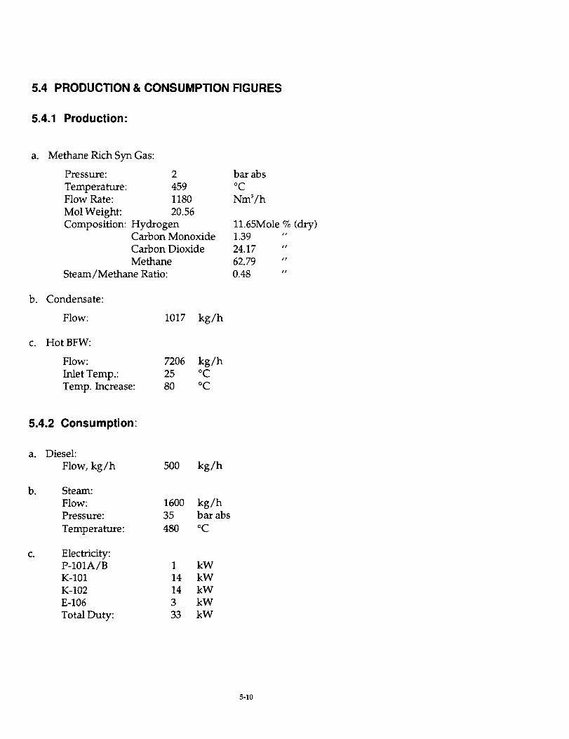
5.4 PRODUCTION & CONSUMPTION FIGURES
5.4.1 Production:
a°
b°
c.
Methane Rich Syn Gas:
Pressure: 2 bar abs
Temperature: 459 °CFlow Rate: 1180 Nm3/h
Mol Weight: 20.56
Composition: Hydrogen 11.65Mole % (dry)Carbon Monoxide 1.39 "
Carbon Dioxide 24.17 "
Methane 62.79 "
Steam/Methane Ratio: 0.48 "
Condensate:
Flow: 1017 kg/h
Hot BFW:
Flow: 7206 kg/h
Inlet Temp.: 25 °C
Temp. Increase: 80 °C
5.4.2 Consumption:
a. Diesel:
Flow, kg/h 500 kg/h
b. Steam:
Flow: 1600 kg/hPressure: 35 bar abs
Temperature: 480 °C
c. Electricity:P-101A/B 1 kW
K-101 14 kW
K-102 14 kW
E-106 3 kW
Total Duty: 33 kW
5-10

5.4.3 Vessels
Item No.
B-101
DescriptionReformed Gas
Separator
[D, mm
5OO
t-t, m m
3500TypeVertical with
Demistics
Design .TP. °c/bar
90C/22.5
Material
SS316
5.4.4 Misc.
Item No.
X-100Description
PSA Unit
Type
Package Unit
5.4.5 Heat Exchangers
Item No.
E-101
E-102
E-103
E-104
E-106
E-107
Description
Recycle Cooler
Feed/Effluent
Exchanger
Feed
Vaporizer
PSA off-gasHeater
Air Cooler
BFW Preheater
TEMA
Type
BEM
BEM
BEM
BEM
BEM
Area m 2
2.6
2.7
4.7
11.8
9.9
Design T/P °C/bar
Shell
560/24
520/30
415/50
150/23
Tube
460/24
550/30
500/50
270/93
Material
Shell
SS
SS
SS
CS
CS
Tube
SS
SS
SS
SS
SS
5.4.6 Pumps
Item No.
P-101AIBDescription
Feed Pumps
TyPe
Positive
Displacement
Metering
Driver
Electric
Motor
Horsepower, kw
1
5-11

5.4.7 Compressors
Item No.
K-101
K-102
Description
PSA off-_as Blower
Hydrogen Recycle
Compressors
I Type
Rotary
Reciprocating
Driver
Electric Motor
Electric Motor
Horsepower, kw14.3
13.5
5.4.8 Reactors
Item No.
R-101
R-102A/B
R-103
Description
Hydrogenator
Desulh.n4zer
Prereformer
ID, MM
600
1400
]]1430
t-t, mm
4320
4740
4000
Design T/P,°C/bar
450/52
450/52
580 / 23.2
Material
SA-204 Grade A
SS-204 Gr. A
SA-204 Gr. 304 N
5-12

Contents
6. DISCUSSION ................................................................................................................................................ 6-1
iii

6. DISCUSSION
The design requirements set for the LFP required that all hydrogen needed for the
hydro-desulfurization process be supplied by systems internal to the LFP. The design solution
to accomplish this resulted in the use of a pressure swing adsorption unit and consequently a
low fuel delivery pressure to the fuel cell system. Thus, even though the LFP has a very high
nominal working pressure [circa 35 bar], the fuel delivery pressure to the fuel cell is 2 bar
requiring a fuel compressor to increase the pressure to approximately 4 bar.
During start-up it is assumed that raw diesel fuel, stored process water, stored nitrogen,
and stored hydrogen are available. During normal operation no stored consumable other than
raw liquid diesel are necessary. For start-up it is assumed that the gas turbine systems will be
fired with liquid diesel or jet fuel to provide electrical power, with the thermal management
system recovering this heat for heating process air to the SOFC and raising steam for the LFP.
Not shown in the process flow diagram are two duct burners that will be necessary to achieve
start-up, the first in the process air stream to the fuel cell to assist in its temperature
maintenance, and the second at the inlet to the heat recovery train to assist in the raising of
steam during start-up. Some hydrogen is necessary to initiate operation of the desulfurizer and
some hydrogen or equivalent is necessary in a reducing cover gas [3% hydrogen in nitrogen
equivalent] to protect the SOFC anode at elevated temperature non-power producing states
such as during start-up and shutdown. Estimated start-up time for the PSOFC/GT system
given a methane rich fuel stream is eight to twelve hours. The start-up time for the LFP is
approximately twice this and therefore limiting.
Water for LFP process purposes is recovered by condensation from the LFP feed to the
SOFC system and from the SOFC spent anode gas. This condensation is accomplished against
ambient air as the heat sink for several practical reasons. First, the LFP and the SOFC are
located at significant separation distance making transport of heat an issue. Second, the gas
streams from which water is to be condensed are very hot, limiting the practical choice for a
heat sink fluid to a gas, especially when considering start-up, off design, and upset conditions.
6-1

The efficiency of the power system could be improved if this condensation energy could be
fully applied to process steam generation.
Present Westinghouse SOFC stack technology utilizes an elegant seal-less design which
requires no high integrity seals between cell elements, cells, or stack and manifolds. In order to
recover sufficient process water to satisfy the LFP, the SOFC stack design must be modified so
as to separately remove from the stack the spent anode gas and the spent cathode gas. In the
present design, these two streams meet in a combustion zone. The separation between the
active stack and the spent fuel plenum, and between the spent fuel plenum and the combustion
zone is accomplished with ceramic insulation board baffles which are of a controlled leakage
design so that by pressure balance the various zones are sufficiently isolated. In order to
permit the extraction of all or at least most of the spent fuel not recirculated for methane
reformation, the barrier between the spent fuel plenum and the combustion zone must be
redesigned for higher flow impedance, and an additional exit penetration must be installed.
The detailed design to accomplish this has not been performed, and the concepts under
consideration must be verified by experiment in at least a bundle test.
The heat recovery section for the PSOFC/GT has been sized and analyzed to supply the
entire heat burden for generating steam for the LFP from condensate. Inspection of the process
flow diagram for the LFP shows a boiler feed water heater that could supply a fraction of this
heat. In addition, within the PSOFC/GT system, the inlet fuel cooler/condenser and the spent
anode gas condenser represent additional potential places where recovered heat could be used
to reduce the heat burden on the SOFC heat recovery train. The design effort to accomplish
this higher degree of thermal integration has not been expended. The estimated gain in system
efficiency at design that thereby has been foregone is a few points. The tighter integration
would most likely reduce operational flexibility. In addition, a coordinated trade-off study to
optimize the operating pressure of the LFP considering the impact upon overall system
efficiency has not been conducted. As pointed out in the PSOFC/GT design description, the
thermal burden upon the SOFC thermal management system would be reduced considerably
and system efficiency improved if lower pressure steam could be used by the LFP.
The PSOFC stack design uses in-stack reformers for natural gas [methane]. The catalyst
in these in-stack reformers could be reformulated for higher hydrocarbons such as desulfurized
diesel if the recirculation ratio of spent fuel to fresh fuel could be increased so as to ensure
6-2

sufficient water vapor and CO 2 to suppress carbon deposition and support diesel reformation.
Unfortunately, the ejector concept can not yield the required recirculation ratio. A mechanical
pump could yield the required recirculafion ratio. The stack would require desulfurized diesel
fuel however. The analysis of this system has been beyond the resources and constraints of
this program.
The system configuration adopted for the preliminary design uses three PSOFC/GT
systems of nominally 1 MW capacity interfacing with a single LFP. This configuration is
judged to have the greatest operational flexibility and the highest probability of power
generation availability. Perturbing the design to use two SOFC three-packs instead of three
twin-packs and one or two gas turbines instead of three presents no particular challenge given
the modularity of the fuel cell and the availability of small turbines. There is the potential to
gain perhaps a point or two in efficiency because of lower heat losses and the higher inherent
efficiency of larger turbo machines. The choice of SOFC twin-packs has been influenced in part
by the fact that in the relatively near term Westinghouse plans to demonstrate a natural gas
fueled system utilizing a pressurized SOFC twin-pack and a single GT.
6-3

7. CONCLUSIONS
1) A PSOFC/GT combined cycle electric power generation system and a LFP can be
integrated to produce a power plant for military fixed-base application fueled by either
DF-2 diesel or JP-8 turbine fuel with an electric generation efficiency [net ac/LHV] greater
than 50 percent [estimating LFP parasitic electric power at one percent of power plant
rating, or 30 kW and limiting thermal integration to the PSOFC/GT exhaust stream] that
requires no process water.
2) The imposition of water neutrality on a system configuration utilizing an external LFP
requires that the existing Westinghouse seal-less SOFC stack design be modified to permit
separate exodus of spent anode gas and spent cathode gas so that process water for the LFP
can be recovered from the spent anode gas. This design change may compromise an
elegantly simple stack design and therefore represents a technical risk.
3) The thermal burden of hydro-desulfurization, plus adiabatic reformation dependent upon
separation of water from fuel gas by condensation and the subsequent generation of steam
from the condensate penalizes design basis system efficiency by ten points relative to the
performance achievable by the PSOFC/GT using natural gas fuel [63%].
4) At the expense of increasing system complexity and decreasing operating flexibility the
design point efficiency of the design basis system could be improved an estimated 3 to 5
points by tighter thermal integration.
5) The gain in power generation efficiency of a factor of two over simple gas turbine engine
generator sets comes at the expense of more complexity, a longer start-up cycle, and
considerably more real estate.
7-1

6) The PSOFC/GT/LFP military fixed-base power system is best suited to relatively stable
locations with a continuous but not necessarily steady requirement for electric power, and
considerable expense associated with delivery of fuel.
7-2
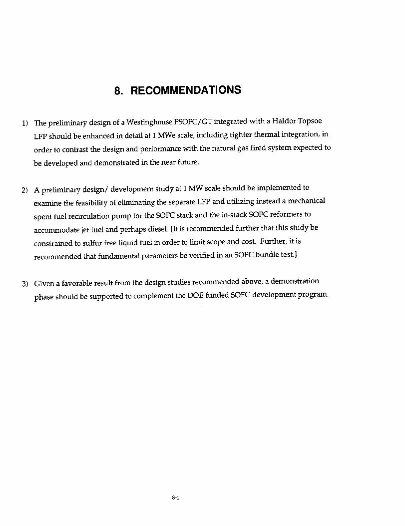
8. RECOMMENDATIONS
1) The preliminary design of a Westinghouse PSOFC/GT integrated with a Haldor Topsoe
LFP should be enhanced in detail at I MWe scale, including tighter thermal integration, in
order to contrast the design and performance with the natural gas fired system expected to
be developed and demonstrated in the near future.
2) A preliminary design/development study at 1 MW scale should be implemented to
examine the feasibility of eliminating the separate LFP and utilizing instead a mechanical
spent fuel recirculation pump for the SOFC stack and the in-stack SOFC reformers to
accommodate jet fuel and perhaps diesel. [It is recommended further that this study be
constrained to sulfur free liquid fuel in order to limit scope and cost. Further, it is
recommended that fundamental parameters be verified in an SOFC bundle test.]
3) Given a favorable result from the design studies recommended above, a demonstration
phase should be supported to complement the DOE funded SOFC development program.
8-1

9. NEW TECHNOLOGY
9.1 NON-PATENTABLE DISCOVERIES
The use of a mechanical anode gas recirculator in lieu of an ejector will enable very high
spent fuel recirculation ratios which may permit the direct use of desulfurized logistic fuels in
the SOFC stack.
9.2 PATENTABLE INVENTIONS
None.
9-1

APPENDIX A
Pressure Vessel Components engineering analysis per _e ASME Boiler and PressureVessel Code, Section VIII, Division 1
A-t

Westinghouse Energy Center
August 30, 1996
ASME Section VIII, Division 1
1992 Edition, 1993 addenda
Advanced Pressure Vessel
Version 5.41a Page 1 of
Job/Quote No : 1 Customer:
Shell Desc. : SOFC HOR!Z. CYL.
Designed: P._ Design Date: August 30, 1996
Checked : Approved:
External loads do not control design.
Cylindrical Shell - Internal Pressure
Design Pressure : 150.00 PSI
Shell Material : SA-516, Grade 70
Mat! stress(hot): 17500 PSI
Shell Length : 300.000 In.
Shell Area : 1004.7 Sq. Ft.
Shell Weight : 40675.0 Lbs.
Specific Gravity: 1.0000
Weight of Fluid : 195601 Lbs.
Actual Stress : 17457 PSI
Static Head: 0.00 PSI
Joint Efficiency: 70 Pct.
Design Temperature: 70 °F
Material stress (cold): 17500 PSI
Corrosion Allowance : 0.0625 In.
Outside diameter :153.5000 In.
Shell Estimated Volume: 23413.9 Gal.
Total Flooded Shell Weight:236276.3 Lbs.
Actual Longitudinal Stress: 8621 PSI
Min. temp curve : BPressure at MDMT:
UCS-66 (b) reduction:
Minimum Design Me=al Temperature:
150.00 PSI Computed minimum temperature:
Yes UCS-68(c) reduction:
-20 OF
Ii OF
No
Longitudinal S_ress Calcula_iorus - UG-27 (c) (2) :
t = PR /(2SE +0.4P) =150 * 75.8125 /(2 * 17500 * 0.70 + 0.4 * 150)
n = 0.4630 +0.0625 (corrosion) = 0.5255 In. rain
Design Thickness per Appendix l-l(a)(i)Circ_unferential S_-Tess Calculations :
t = PRO /(SE +0.4P) = 150 * 76.7500 / (17500 * 0.70 + 0.4 * 150)
U = 0.9353 +0.0625 (corrosion) = 0.9978 In. rain
NOMINAL SHELL THICKNESS SELECTED - 1.0000 Inches
A-2

Job/Quote No : 1
Head Desc. : COVER
Designed: P._
Checked :
Westinghouse EnergyCenter
August 30, 1996
ASME Section VIII, Division 1
1992 Edition, 1993 addenda
Advanced Pressure Vessel
Version 5.41a Page 2 of
Customer:
Design Da_e: August 29, 1996
Approved:
External loads do not control design.
E!lipsoidal Head - Internal Pressure
Design Pressure : 150.00 PSI
Head Material : SA-516, Grade 70
Marl stress(hot): 17500 PSI
Actual Stress : 16254 PSI
Head Location : Bottom
Head Quantity : 2
Total Head Area : 361.5 Sq. Ft.
Total Head Wt. : 16571.9 Lbs.
Specific Gravity: 1.0000
Static Head: 0.00 PSI
Joint efficiency: 70 Pct.
Design Temperature: 70 °FMaterial stress (cold): 17500 PSI
Corrosion Allowance: 0.0625 in.
Outside diameter :153.5000 In.
Total Head Est. Volume: 4155.2 Gal.
Weight of Fluid : 34655 Lbs.
Total Flooded Head Weight: 51226.6 Lbs.
Straight Flange : 1.5000 In. Thin Out : 0.0625 In.
Head Depth (ho) : 38.9375 In. K t 1/6 [2 + Sq (D/2h)] : 1.00
7
Min. temp curve : B Minimum Design Metal Temperature: -20 °F
Pressure at MDMT: 150.00 PSI Computed minimum temperature: 8 °F
UCS-66(b) reduction: Yes UCS-68(c) reduction: No
Design Thickness per APPENDIX I-4(c)t = PDoK / (2 SE + 2 P(K - 0.I))
t = 150 * 153.5000 * 1.00 / (2 *17500 * 0.70 + 2 * 150 (I.00 - 0.I))
t = 0.9296 +0.0625 (corrosion) +0.0625 (thin out) = 1.0546 In. mi_.
NOMINAL HEAD THICKNESS SELECTED - 1.1250 Inches
A-3

ASMEAppendix 2 - Flange Design, Type: Integral Type
Job/Quote Number : 1 Page 3 of 7Flange description: SIDE FLANGES
_sign Pressure : 150.00 PSI
.lange Material : SA-105
Hot Stress (Sfo) : 17500 PSI
Flange Weight : 18873 ib
Design Temperature: 70 °F
Cold Stress (Sfa): i7500 PSI
Flange MAWP (at design): 0.00 PS_MDMT Calculations
Min. temp. curve : B Minimum Design Metal Temperature: -20 °F
Pressure at MDMT: 150.00 PSI Computed minimum temperature: 104 °FUCS-66(b) reduction: Yes UCS-68(c) reduction: No
Bolting Material: SA-193, Grade B7,>=2.5-4-
Hot Stress _(Sb) : 97000 PSi Cold Stress (Sa) : 97000 PSI
Wall Material : SA-516, Grade 70
Hot Stress (Sno) : 17500 PSI Cold Stress (Sna) : 17500 PSI
Wall thickness, in: 1.0000 in. Integral type config.: Fig. 2-4(6)
Gasket and Facing Details
Gasket Material : Spiral wound metal, asbestos filled
Gasket Type : Carbon Gasket Factor m: 2.50
Configuration : Full face Seating stress y: I0000 PSI
Bolting Details
Number of bolts : 60 Nominal bolt diameter (a) : 2.7500 in.
8olt root area : 5.2590 in'2 Bolt correction factor applied: No
Flange Dimensions
3olt circle (C) :160.7500 in. Outside diameter (A) :166.0000 in.
"nside diameter :151.5000 in. Corrosion Allowance: 0.0625 in.
_rroded I.D.(B):ISI.6250 in. , Hub thickness at small end: 1.0000 in.
{ub length (h) : 3.0000 in. Hub thickness at large end: 1.2500 in.Gasket Calculations
= (C - B) / 4 = (160.7500 - 151.6250) / 4 = 2.2813 in.
LG = (C - B) (2B + C) / (6 (B + C)) = 2.2590 in.
_G' = (A- C)(2A + C) / (6 (C + A)) = 1.3195 in.
_ = C - 2 hG = 160.7500 - 2 * 2.2590 = 156.2320 in.
Load and Bolting Calculations
Gy = (Pi)bGy = Pi * 2.2813 * 156.2320 * I0000 = 11197015 ib
Gy' = (hG / hG') HGy = (2.2590 / 1.3195} * 11197015 = 19169425 lb
m2 = HGy + HGy'= 11197015 + 19169425 - 30366440 ib
= (Pi/4) (G'2)P = (Pi / 4) * Sqr(156.2320) * 150.00 = 2875551 lb
= 2b(Pi)GmP = 2 * 2.2813 * Pi * 156.2320 * 2.50 * 150.00 = 839776 Ib
7' = (hG / hG') Hp = (2.2590 / 1.3195) * 839776 = 1437707 ib
•i = H + Hp + Hp'= 2875551 + 839776 + 1437707 = 5153034 ib
_11 = Wm! / Sb = 5153034 / 97000 = 53.1241 in'2
= Wm2 / Sa = 30366440 / 97000 = 313.0561 in'2
I = greater of Aml or Am2 = greater of 53.1241 or 313.0561 = 313.0561 in'2
= No. of bolts * Bolt root area = 60 * 5.2590 = 315.5400 in'2
= (Am + Ab)Sa/2 = (313.0561 + 315.5400) * 97000 / 2 = 30486911 ib
Moment Calculations - Operating Conditions
= (Pi/4)(B'2)P = (Pi / 4) * Sqr(151.6250) * 150.00 = 2708462 ib= H - _ = 2875551 - 2708462 = 167089 ib
= ((C - B) / 2) - gl = ((160"7500 - 151.6250) / 2) - 1.1875 = 3.3750 in.
= R + (g! / 2} = 3.3750 ÷ (1.1875 / 2) = 3.9688 in.
= (R + gl + hG) / 2 = (3.3750 + 1.1875 + 2.2590) / 2 = 3.4108 in.
= _D * hE = 2708462 * 3.9688 = 10749344 in.-ib
= h_f * hT = 167089 * 3.4108 = 569.907 in.-Ib
= MD + MT + = 10749344 + 569907 = 11319251 in.-!b
A_

Job/Quote Number : 1 Page 4 of 7
Radial Bending Stress at Bolt Centerline
"G = W - H = 30486911 - 2875551 = 27611360 113
_" = hG hG' / (hG + hG') = 2.2590 * 1.3195 / (2.2590 + 1.3195) = 0.8330 in...,G = HG * hG" = 27611360 * 0.8330 = 23000263 in.-Ib
Shape co_._ta_ts
Calculated from FIG. 2-7.1, where K = A / B = 166.0000 / 151.6250 = 1.0948
T = 1.8791 U = 23.4813 Y = 21.3680 Z = 11.0712
h0 = SqRt(B * gO) = SqRt(151.6250 * 0.9375) = 11.9226 in.
h / h0 = 3.0000 / 11.9226 = 0.2516 gl / gO = 1.1875 / 0.9375 = 1.2667
Calculated from equations from TABLE 2-7.1 :
F = 0.8935 V = 0.4429 f = 1.0000
d = (U / V) h0(g0"2) = (23.4813 / 0.4429) * 11.9226 * Sqr(0.9375) = 555.5587e = F / h0 = 0.8935 / 11.9226 = 0.0749
L = ((re + I) / T) + (t'3 / d) = ((8.9884 * 0.0749 + I) / 1.8791) +
(8.9884"3 / 555.5587) = 2.1976
Minimum thickness calculations
Minimum thickness = 8.9884 in. Nominal _hick_ess = 9.0000 in.
Bolting moment correction factor was no_ considered (Cf = I).
Stress Calculations - Operating Conditions
SH = f Cf Mo / (L (gl'2) B) =
1.0000 * 1.0000 * 11319251 / (2.1976 * Sqr(I.1875) * 151.6250) = 24090 PSISR = ((4/3)re + i) Cf Mo / (L (t'2) B) =
((4/3) * 8.9884 * 0.0749 + I) * 1.0000 * 11319251 /
(2.1976 * Sqr(8.9884) * 151.6250) = 798 PSI
ST = (X Cf Mo / (B t'2)) - (Z SR) =
(21.3680 * 1.0000 * 11319251 / (151.6250 * SQT(8.9884))) -(11.0712 * 798) = 10910 PSI
(SH + SR) / 2 = 12444 PSI
(SH + ST) / 2 = 17500 PSI
SHmax = smaller of 1.5 Sfo or 2.5 Sno = 26250
Since, (SH <-- SHmax), (SR <= Sfo), (ST <= Sfo),
((SH + SR) / 2 <= Sfo), and ((SH + ST) / 2 <= Sfo) then
minimum thickness is adequate for operating conditions.
Stress Calculations - Radial Bending at Bolt Centerline
SR = (6 MG) / (t'2 * (Pi C - n dl)) =
(6 * 23000263) / (Sqr(8.9884) * (Pi * 160.7500 - 60 * 2.8750)) - 5024 PSI
Since (SR <= Sfo), minimum thickness is adequate for radial bending.
Ab _=Am, bolting is adequate for flange design.
_ninal t >= Minimum t, flange _hickness is adequate for flange design.
A-$

Job : 1
-em
-- MAW? Report by Component --
Design S_a=ic MAWPPressure Head New & Cold
Page 5 of 7
MAW?
Hot & Corr.
SOFC HORIZ. CYT_. 150.00 0.00 160.45
COVER 150.00 0.00 171.72
-- SUMMARY --
New and cold component with lowest MAWP: (MAW_ = 160.45 PSI)
SOFC HORIZ. CYL.
Hot and corroded component with lowest MAWP: (MAWP = 150.37 PSI)SOFC HOKIZ. CTL.
Pressures are exclusive of any externa! loads.
150.37
161.50
A_

-- MDMTReport by Component --Job: 1 Page
_em Material Curve Pressure
6 of 7
MD_r
SOFC XORIZ. CYL. SA-516, Grade 70 B 150.00
COVER SA-516, Grade 70 B 150.00
-- S_ARY --
* - indicates one or more components do not meet the design MDMT of -20.
Ao7

•JOb: 1
WEIGHTS:
Shell weightHead weight
-- Vessel Summary --
40675 Lbs.16572 Lbs.
Page 7 of
flooded
236276 Lbs.
51227 Lbs.
7
Total Weights 57247 Lbs. 287503 Lbs.
VOLUME=
Shell volume
Head volume
23414 Gallons
4155 Gallons
Total Volume 27569 Gallons
ARY_A=
Shell area
Head area
I005 Sq. Ft.
361 Sq. Ft.
Total Area 1366 Sq. Ft.
HYDRO TEST INFORMATION
Gauge at Top
Controlling Components
Ratio: SOFCKORIZ. CYL.
Pressure: SOFCHORIZ. CYL.
Design Pressure * 1.5 * (Cold Stress / Hot Stress) - Hydro Test Pressure
150.00 * 1.5 _ ( 17500 / 17500 } - 225.00 PSI
A4