FTM103-chapter2-stalls.pdf
49
7/15/2019 FTM103-chapter2-stalls.pdf http://slidepdf.com/reader/full/ftm103-chapter2-stallspdf 1/49 2.i CHAPTER TWO STALLS PAGE 2.1 INTRODUCTION 2.1 2.2 THEORY 2.3 2.2.1 Wing Design 2.3 2.2.1.1 Wing Section Characteristics 2.3 2.2.1.2 Wing Planform Characteristics 2.5 2.2.1.3 Effects of High Lift Devices 2.9 2.2.2 Horizontal Tail Design and Location 2.11 2.2.3 Acceleration 2.14 2.2.4 Power 2.16 2.2.5 Stability and Control Augmentation 2.16 2.2.6 Miscellaneous Factors 2.20 2.2.7 Characteristics Which May Limit Minimum Steady Airspeed 2.21 2.2.7.1 Loss of Control Without Reduction of Lift 2.21 2.2.7.2 Lack of Longitudinal Control Effectiveness 2.22 2.2.7.3 “Zero Rate of Climb Speed” 2.22 2.2.8 Stall Warning and Stall Prevention Devices 2.24 2.2.8.1 Artificial Stall Warning 2.24 2.2.8.2 Artificial or Automatic Stall Prevention 2.25 2.3 TEST PROCEDURES AND TECHNIQUES 2.26 2.3.1 Preflight Procedures 2.26 2.3.2 Flight Test Techniques 2.30 2.3.2.1 The Controlled Stall Test Technique 2.30 2.3.2.2 Approach to the Stall 2.30 2.3.2.3 Fully Developed Stall 2.32 2.3.2.4 Stall Recovery 2.33 2.3.2.5 Profile of the Controlled Stall Test Technique 2.34 2.3.2.6 Alternate Technique for Accelerated Stall Investigations 2.37 2.3.2.7 Simulated Inadvertent Stalls 2.37
description
Investigation of stall characteristics
Transcript of FTM103-chapter2-stalls.pdf

7/15/2019 FTM103-chapter2-stalls.pdf
http://slidepdf.com/reader/full/ftm103-chapter2-stallspdf 1/49
2.i
CHAPTER TWO
STALLS
PAGE2.1 INTRODUCTION 2.1
2.2 THEORY 2.3
2.2.1 Wing Design 2.3
2.2.1.1 Wing Section Characteristics 2.3
2.2.1.2 Wing Planform Characteristics 2.5
2.2.1.3 Effects of High Lift Devices 2.9
2.2.2 Horizontal Tail Design and Location 2.11
2.2.3 Acceleration 2.14
2.2.4 Power 2.16
2.2.5 Stability and Control Augmentation 2.16
2.2.6 Miscellaneous Factors 2.20
2.2.7 Characteristics Which May Limit Minimum Steady Airspeed 2.21
2.2.7.1 Loss of Control Without Reduction of Lift 2.21
2.2.7.2 Lack of Longitudinal Control Effectiveness 2.22
2.2.7.3 “Zero Rate of Climb Speed” 2.22
2.2.8 Stall Warning and Stall Prevention Devices 2.242.2.8.1 Artificial Stall Warning 2.24
2.2.8.2 Artificial or Automatic Stall Prevention 2.25
2.3 TEST PROCEDURES AND TECHNIQUES 2.26
2.3.1 Preflight Procedures 2.26
2.3.2 Flight Test Techniques 2.30
2.3.2.1 The Controlled Stall Test Technique 2.30
2.3.2.2 Approach to the Stall 2.30
2.3.2.3 Fully Developed Stall 2.32
2.3.2.4 Stall Recovery 2.33
2.3.2.5 Profile of the Controlled Stall Test Technique 2.34
2.3.2.6 Alternate Technique for Accelerated Stall Investigations 2.37
2.3.2.7 Simulated Inadvertent Stalls 2.37

7/15/2019 FTM103-chapter2-stalls.pdf
http://slidepdf.com/reader/full/ftm103-chapter2-stallspdf 2/49
FIXED WING STABILITY AND CONTROL
Theory and Flight Test Techniques
2.ii
2.3.3 Postflight Procedures 2.38
2.4 SPECIFICATION REQUIREMENTS 2.39
2.5 GLOSSARY 2.41
2.6 REFERENCES 2.43

7/15/2019 FTM103-chapter2-stalls.pdf
http://slidepdf.com/reader/full/ftm103-chapter2-stallspdf 3/49
STALLS
2.iii
CHAPTER TWO
FIGURES
PAGE2.1 Types of Section Stall 2.4
2.2 Influence of Shape of Lift Curve on Stall Characteristics 2.5
2.3 Typical Influence of Aspect Ratio and Sweepback on Lift Curve Slope 2.6
2.4 Downwash Influence on Section Angle of Attack 2.7
2.5 Typical Influence of Wing Taper on Stall 2.8
2.6 Effect of Boundary Layer Control on Lift Curve 2.10
2.7 Typical Flow Patterns About the Low-Mounted Horizontal Tail 2.12
2.8 Typical Flow Patterns About the T-Tail 2.13
2.9 Aft-Fuselage Mounted Engines Complicate the T-Tail Airflow
Disturbance at High Angles of Attack 2.14
2.10 Accelerated Stall Time History 2.18
2.11 Normal Stall Time History 2.19
2.12 Typical Flow Pattern Around the Vertical Tail at High Angle of Attack 2.21
2.13 Typical Variations of Lift and Drag Coefficient for the Low Aspect
Ratio Airplane 2.23
2.14 Typical Stall Data Card 2.29
2.15 General Profile of the Controlled Stall Investigation 2.342.16 Typical Stall Data Table 2.39

7/15/2019 FTM103-chapter2-stalls.pdf
http://slidepdf.com/reader/full/ftm103-chapter2-stallspdf 4/49
FIXED WING STABILITY AND CONTROL
Theory and Flight Test Techniques
2.iv
CHAPTER TWO
TABLES
PAGE
2.I Summary of Stall Warning Devices 2.25

7/15/2019 FTM103-chapter2-stalls.pdf
http://slidepdf.com/reader/full/ftm103-chapter2-stallspdf 5/49
STALLS
2.v
CHAPTER TWO
EQUATIONS
PAGE
VS = 2nW
ρCLmaxS
eq 2.1 2.14

7/15/2019 FTM103-chapter2-stalls.pdf
http://slidepdf.com/reader/full/ftm103-chapter2-stallspdf 6/49
2.1
CHAPTER TWO
STALLS
2.1 INTRODUCTION
All airplanes are subjected to stall investigations for the following reasons:
1. Safety and operational considerations.
2. Actual flight tests are the only means of precisely determining stall
characteristics.
3. Expansion of the operational flight envelope.
4. Determination of trim airspeeds for future tests.
The investigation of stall characteristics is a phase of flying qualities which is
difficult to associate with particular pilot tasks . There are no total missions in which stalls
are required for mission accomplishment, although pilot training and familiarization in stall
characteristics are considered an essential phase of the training mission . However, all
airplanes will be stalled at one time or another in operational use if sufficient longitudinal
control is available and if no stall prevention device is installed. Therefore, stall tests are an
integral part of any flying qualities program.
The emphasis placed on the stall investigation depends on the total mission of the
airplane. If mission accomplishment involves a great deal of maneuvering, the pilot is very
likely to inadvertently stall; therefore, a thorough stall investigation must be carried out. If
mission accomplishment involves a minimum of maneuvering, the pilot is not likely toinadvertently stall; therefore, the stall investigation may be less stringent.
Stall investigations encompass both normal and accelerated stalls. The normal stall
is defined as a stall which occurs while the airplane is in an unaccelerated flight condition.
The accelerated stall is defined as a stall which occurs while the airplane is in an accelerated

7/15/2019 FTM103-chapter2-stalls.pdf
http://slidepdf.com/reader/full/ftm103-chapter2-stallspdf 7/49
FIXED WING STABILITY AND CONTROL
Theory and Flight Test Techniques
2.2
flight condition, such as a pull-up or a level turn. Accelerated stalls usually exhibit more
violent characteristics than normal stalls; therefore, normal stalls should be investigated
thoroughly before commencement of accelerated stall tests. The total mission of the
airplane dictates where the primary emphasis is placed during the stall investigation. For
the airplane which will be maneuvered extensively, primary emphasis must be placed on
accelerated stalls which could result from mission tasks. If mission accomplishment
involves a minimum of maneuvering, primary emphasis should be placed on normal stall
characteristics. The large passenger, transport, or heavy bomber type airplane will most
likely be inadvertently stalled in unaccelerated flight during transitions associated with
instrument departures or approaches.
Normal and accelerated stalls may be further classified as “positive g” or “negative
g” stalls. This discussion of stall characteristics will be concerned only with “positive g”normal and accelerated stalls because:
1. Normal “negative g” stalls are difficult to obtain in most operational airplanes
due to insufficient longitudinal control effectiveness.
2. Precise pilot technique is required to perform “negative g” accelerated stalls
(stalls entered at less than -1.0g).
3. Pilot discomfort discourages entry into “negative g” normal or accelerated stalls.
“Negative g” normal and accelerated stalls maybe investigated in a build-up
program for spin testing, which will be discussed in a subsequent section.
Normal and accelerated stall characteristics indirectly affect mission performance of
the pilot - airplane combination. Satisfactory stall characteristics greatly increase pilot
confidence in his airplane. When assurance can be provided that violent departures into
uncontrolled flight will not result from inadvertent stalls, the pilot will utilize fully themaneuvering capabilities of the airplane for maximum mission effectiveness.

7/15/2019 FTM103-chapter2-stalls.pdf
http://slidepdf.com/reader/full/ftm103-chapter2-stallspdf 8/49
STALLS
2.3
2.2 THEORY
The classical stall may be defined as a condition in which the airplane wing is
subjected to an angle of attack greater than the angle for maximum lift coefficient. Stall
speed can be defined as the minimum steady airspeed attainable in unaccelerated flight or
the minimum usable airspeed. However, characteristics exhibited by many airplanes in the
region of the stall preclude attainment of the classic aerodynamic stall. These characteristics
vary widely among different airplanes and are greatly affected by a multitude of factors.
The major factors affecting stall characteristics are discussed herein. A resumä of stall
warning and stall prevention devices is also presented.
2.2.1 Wing Design
2.2.1.1 WING SECTION CHARACTERISTICS
Wing section design determines the value of the maximum lift coefficient, the angle
of attack at which it is achieved, and the rate of change of lift coefficient with angle of
attack in the region of the stall. The most influential wing section parameters are the wing
thickness and position of maximum thickness, the amount of camber, and the leading edge
radius.
The influence of airfoil thickness and camber on maximum lift coefficient is quite
pronounced. A thin symmetrical airfoil (thickness ratio less than .08) has such a small
leading edge radius that large adverse pressure gradients induce leading edge flow
separations at low angles of attack. The thick (thickness ratio greater than .12) or highly
cambered airfoil creates large adverse pressure gradients near the upper surface trailing
edge which causes separation near the trailing edge at low angles of attack. An airfoil of
moderate thickness (thickness ratio from .08 to .12) and camber may exhibit a tendency for
separation to occur simultaneously at both leading edge and trailing edge (Figure 2.1).
(Note: Positive cambering of a thin symmetrical airfoil generally reduces the tendency for
early separation and increases maximum lift coefficient. However, too much cambering of thick sections can produce the adverse characteristics discussed above.)

7/15/2019 FTM103-chapter2-stalls.pdf
http://slidepdf.com/reader/full/ftm103-chapter2-stallspdf 9/49
FIXED WING STABILITY AND CONTROL
Theory and Flight Test Techniques
2.4
The type of section stall has a great deal of influence on stall characteristics. If
separation occurs first near the trailing edge of the airfoil, the spread of separation forward
is fairly slow and gradual until the maximum lift coefficient is attained. This type of
separation progression indicates that the lift curve would exhibit a smooth, gradual change
in slope near the stall, although the stall would be rather well-defined. An airplane having
this type of lift coefficient - angle of attack relationship would probably exhibit satisfactory
stall warning and a well-defined aerodynamic stall (Figure 2.2).
The second lift curve of Figure 2.2 also exhibits a well-defined peak, however, the
peak is followed by a very rapid, even discontinuous, decrease in lift coefficient for a smallincrease in angle of attack. This type of lift curve can result from leading edge flow
separation spreading rapidly aft on the airfoil or simultaneous leading edge-trailing edge
separation. The airplane with this type of lift curve would exhibit little or no aerodynamic
stall warning and a sudden, abrupt stall. This stall may be quite violent because the
sharpness and discontinuity of the lift curve indicate that one wing can easily stall prior to
Leading Edge SeparationSpreading AFT
Thin SymmetricalSection
Thick or Highly CamberedSection
Trailing Edge SeparationSpreading Forward
Separation Spreading AFTand Forward
Section of ModerateThickness and Camber
Figure 2.1Types of Section Stall

7/15/2019 FTM103-chapter2-stalls.pdf
http://slidepdf.com/reader/full/ftm103-chapter2-stallspdf 10/49
STALLS
2.5
the other generating rolling motion at the stall. This “asymmetric” stall can be caused by
small difference in wing sections along the span or small differences in local flow direction
due to vertical gusts or yawing motion. In any case, the downgoing wing experiences an
increase in angle of attack, while the upgoing wing experiences a decrease. This situation
may result in autorotation , a motion in which the rolling is self-sustaining and which mayresult in the airplane entering a spin. The abrupt, “asymmetric” stall tendency may be
overcome by increasing the radius of the leading edge of the wing and/or by cambering the
wing judiciously. If this approach is not practical, some improvement in stall
characteristics may be realized by installing devices on the wing leading edge to introduce
turbulence into the boundary layer. However, this correction is usually a “trial and error”
process.
2.2.1.2 WING PLANFORM CHARACTERISTICS
Wing planform design influences the slope of the lift curve - angle of attack
relationship, downwash pattern, and the portion of the wing span which stalls first. The
most influential planform parameters are aspect ratio, sweep, and taper.
Stall Warning
Stall
L i f t C o e f f i c i e n t
C L
+
+Angle of Attack α
Gradual, Well Defined StallInitial Separation at Trailing Edge
Stall
Stall Warning
L i f t C o e f f i c i e n t
C L
Angle of Attack
+
+
α
Abrupt StallInitial Separation at Leading Edge
orSimultaneous Separation at Leading
and Trailing Edges
Figure 2.2Influence of Shape of Lift Curve on Stall Characteristics

7/15/2019 FTM103-chapter2-stalls.pdf
http://slidepdf.com/reader/full/ftm103-chapter2-stallspdf 11/49
FIXED WING STABILITY AND CONTROL
Theory and Flight Test Techniques
2.6
The slope of the lift curve at airspeeds near stall is determined primarily by aspect
ratio and sweep angle. An increase in aspect ratio1 increases the slope of the lift curve,
while an increase in sweepback decreases the slope (Figure 2.3).
The slope of the lift curve influences the angle of attack and pitch attitude at which
the aerodynamic stall is encountered. If the slope of the lift curve is shallow, the angle of
attack for the stall may be attained only at a very high airplane nose attitude and with a very
large rate of descent. Furthermore, adverse stability and control characteristics may be
encountered before the attainment of the maximum lift coefficient. Therefore, airplanes
with low aspect ratio and highly swept wings generally do not exhibit a true aerodynamic
stall and a “minimum flying speed” would be determined based on other criteria.
Downwash is the unavoidable result of lift production by a real wing. It reduces
the angle of attack at which individual wing sections operate (Figure 2.4).
1 Aspect ratios of 3 to 6 are considered “medium,” above 6 are considered “high”, less than 3 are considered
“low”.
L i f t C o e f f i c i e n t
C L
IncreasingAspect Ratio
Angle of Attack +
α
+
L i f t C o e f f i c i e n t
C L
Angle of Attack +
α
IncreasingSweepback
+
Figure 2.3Typical Influence of Aspect Ratio and Sweepback on Lift Curve Slope

7/15/2019 FTM103-chapter2-stalls.pdf
http://slidepdf.com/reader/full/ftm103-chapter2-stallspdf 12/49
STALLS
2.7
The spanwise distribution of downwash dictates the section angle of attack and
hence the section lift-coefficient distribution along the span. This distribution is extremely
important because of its influence on the part of the span to first reach a stalled condition .
The spanwise downwash distribution depends on wing taper and sweep, if the wing has
zero twist and the same section from root to tip. As the degree of taper increases, the area
of first stall on the span moves from root to tip (Figure 2.5). An increase in sweepback has
a similar effect as the increase in taper. The tendency of the wing to stall first at the tips
seriously derogates stall characteristics. While the root stall is generally preceded by
buffeting of the fuselage and tail caused by turbulent air shed from the root section, the tip
stall generally occurs with little or no stall warning . Since the lateral control surfaces are
usually positioned near the wing-tips, loss of roll control is often experienced when the
stall occurs first at the tips.
The swept wing has an inherent tendency toward tip stall because sweep back
changes the spanwise downwash distribution such that the wing area near the tip operates
at larger section angles of attack than other wing areas. This generates a pressure gradient
along the span of the wing with pressure decreasing from root to tip. As a consequence,
considerable spanwise flow of the boundary layer occurs. This spanwise flow from root to
tip may be considered a form of “natural” boundary-layer control for the inboard area of the
wing and increases the already inherent tendency toward tip stall. (Note: It should be
remembered that spanwise flow occurs on any wing planform. However, the swept wing
is particularly prone to spanwise flow).
Tip stalling of the swept wing results in an additional factor which tends to derogate
stall characteristics. Since sweepback places the tips aft of inboard sections, tip stalling
precipitates a forward shift of the wing center of pressure. This cases the wing to become
V elocit y at W ing
Velocity of Free Stream
α = Wing Angle of Attack
αo = Section Angle of Attack
αi = Induced Angle of Attack
αo
αi
α
Figure 2.4Downwash Influence on Section Angle of Attack

7/15/2019 FTM103-chapter2-stalls.pdf
http://slidepdf.com/reader/full/ftm103-chapter2-stallspdf 13/49
FIXED WING STABILITY AND CONTROL
Theory and Flight Test Techniques
2.8
more longitudinally destabilizing ; if the destabilizing influence is greater than the stabilizing
influence of the horizontal tail, the airplane tends to pitch nose-up at the stall. This
characteristic makes the airplane prone to inadvertent stalling and “deep stall” penetrations.
Rectangular
Elliptical
Pointed
Stall Moves from Root Outboard
Elliptical Wing has Constant Downwash andSection Lift Coefficient Along the Span,Therefore Stalls Evenly Across the Span
Stall Moves from Tip Inboard
Figure 2.5
Typical Influence of Wing Taper on Stall

7/15/2019 FTM103-chapter2-stalls.pdf
http://slidepdf.com/reader/full/ftm103-chapter2-stallspdf 14/49
STALLS
2.9
There are several means by which tip stalling tendencies may be decreased or
eliminated. The most common are listed below. They may be used singly or in
combination.
1. Twist: The wing is gradually twisted from root to tip so that outboard sectionsare always at a lower angle of attack than inboard sections (sometime called
washout).
2. Incorporation in the wing tip area of an airfoil section of higher maximum lift
coefficient than inboard sections.
3. Wing tip slots or slats: Spanwise passages near the leading edge to delay
separation at high angles of attack.
4. Wing tip vortex generators: Small spanwise airfoils which introduce a higher
energy level in the boundary layer.
5. Inboard stall strips: Spanwise leading edge protrusions which cause flow
separation at the wing root at high angles of attack.
6. Fences: Thin chordwise strips which inhibit spanwise flow.
7. Leading edge discontinuities: A device which creates a vortex just above the
wing surface to inhibit spanwise flow.
2.2.1.3 EFFECTS OF HIGH LIFT DEVICES
High lift devices are used to increase the maximum lift coefficient of the wing,
allowing stall-free flight at slower airspeeds. Their main influence on stall characteristics is
indirect. With high lift devices operating, the airplane stalls at slower speeds; therefore, the
effectiveness of the aerodynamic control surfaces for controlling airplane attitude in the stallregion is weakened. In addition to this indirect effect common to all high lift devices, some
direct effects of particular devices are discussed below.
Flap deflection changes the spanwise distribution of downwash and hence the
section angles of attack. This change in section angles of attack may cause significantly
different stall characteristics when flaps are deflected.

7/15/2019 FTM103-chapter2-stalls.pdf
http://slidepdf.com/reader/full/ftm103-chapter2-stallspdf 15/49
FIXED WING STABILITY AND CONTROL
Theory and Flight Test Techniques
2.10
Boundary layer control (BLC) tends to change the shape of the lift curve near
stalling angles of attack (Figure 2.6). The sharper peaks of the lift curve, when boundary
layer control is used, make the stall more abrupt and also create the tendency for an abrupt
roll at the stall. In addition, a very large reduction in angle of attack may be necessary to
effect stall recovery.
Slots or slats may be used to improve airflow conditions at high angles of attack.
One means of utilizing these high lift devices is through use of the “automatic slot.” The
automatic slot is a slot in the leading edge of the wing created by the movement of a slat
which is retained in the leading-edge contour of the wing at low angles of attack, but
extends to create the slot as the stalling angle of attack is approached. The slats operate
without action by the pilot and, unless design precautions are taken, have an inherent
tendency to extend and retract asymmetrically. Leading edge slats have exhibited an
annoying propensity toward asymmetric extension during approaches to accelerated stalls.
In this flight regime, their asymmetric extension may generate violent, uncontrollablerolling motion. Asymmetric extension can be eliminated by incorporation of slat
interconnects or a hydraulic device to hold the slats on the leading edge of the wing until the
landing gear or flaps are extended.
High BLC
Low BLC
Basic Section
+
+
L i f t C o e f f i c i e n t
C L
Angle of Attack
α
Figure 2.6Effect of Boundary Layer Control on Lift Curve

7/15/2019 FTM103-chapter2-stalls.pdf
http://slidepdf.com/reader/full/ftm103-chapter2-stallspdf 16/49
STALLS
2.11
2.2.2 Horizontal Tail Design and Location
Horizontal tail design and location have a major influence on stall characteristics.
Since the contributions of the fuselage and wing to longitudinal stability are generally
destabilizing in the stall region, the horizontal tail must provide the necessary stabilizing
pitching moments if the airplane is to remain longitudinally controllable. The vertical
location of the horizontal tail with respect to the wing is of extreme importance for this
dictates the airflow characteristics at the horizontal tail at high angles of attack. A rigorous
discussion of all possible vertical tail locations and associated influences on stall
characteristics is beyond the scope of this text. However, two examples are presented to
demonstrate the problems which exist.
First, consider an airplane design which incorporates a horizontal stabilizer
mounted low on the empennage. At low angles of attack, this tailplane is immersed in
airflow which has been altered by the wing (Figure 2.7). However, at low angles of
attack, there is little loss of stream velocity behind the wing, although the stream is
deflected downward by the downwash angle. The horizontal tail, therefore, maintains its
effectiveness at low angles of attack since the flow field is not too greatly disturbed. As the
angle of attack is increased, airflow begins to breakdown on the wing and loading
distribution and associated changes in downwash occur. The wake behind the wing
becomes more and more nonstreamlined and turbulent. Very low values of dynamic
pressure may exist over an extensive region aft of the wing. If the angle of attack is
increased sufficiently, a complete breakdown of flow spreads over the entire wing and the
stall occurs. However, if the horizontal stabilizer is mounted low on the empennage, the
stabilizer emerges from the wing wake at high angles of attack (Figure 2.7). This causes
the horizontal tail to maintain a strong longitudinally stabilizing influence at the stall,
generating large nose-down pitching moments. In addition, the longitudinal control surface
maintains a high degree of effectiveness throughout the stall, allowing the pilot close
control over pitch attitude.
The placement of the horizontal stabilizer high up on the vertical fin (T-tail) has
become increasingly popular in recent years, particularly for passenger and transport
airplanes. With the appearance of aft fuselage mounted engines (which allowed a
structurally simple and aerodynamically clean wing), the horizontal stabilizer was placed
higher to avoid interference flow and structural fatigue from engine exhaust. The T-tail
also realizes other advantages such as an increase in effectiveness at low angles of attack
since, in that flight regime, it does not operate in the wake of the wing. In addition, it has

7/15/2019 FTM103-chapter2-stalls.pdf
http://slidepdf.com/reader/full/ftm103-chapter2-stallspdf 17/49
FIXED WING STABILITY AND CONTROL
Theory and Flight Test Techniques
2.12
an “endplate effect” on the vertical tail, and thereby increases the effectiveness of that
surface. Unfortunately, the T-tail design causes severe problems at high angles of attack,
particularly at stalling angles of attack.
Insight into the T-tail stall problem can be gained by a study of Figure 2.8. At low
angles of attack, the T-tail receives little or no influence from the downwash caused by lift
production of the wing. However, as the airplane is rotated to higher and higher angles of
attack, the high mounted horizontal stabilizer is moved closer and closer to the now
nonstreamlined, turbulent wake from the wing. In the region of stall, the T-tail may be
engulfed in the wing wake; this results in a drastic reduction in horizontal tail and
longitudinal control effectiveness. The reduction in stabilizing effect from the horizontal
tail causes a severe pitch-up tendency which the pilot may not be able to counteract even by
applying full nose-down longitudinal control. This stall, from which recovery is
impossible without an unconventional recovery technique or a “recovery augmentor,” such
as a tail parachute, is referred to as a “super stall” or “deep stall” and has been experienced
by T-tail aircraft flying at an aft center of gravity position.
High Angle of Attack
Low Angle of Attack
Figure 2.7Typical Flow Patterns About
the Low-Mounted Horizontal Tail

7/15/2019 FTM103-chapter2-stalls.pdf
http://slidepdf.com/reader/full/ftm103-chapter2-stallspdf 18/49
STALLS
2.13
The problem of the T-tail entering disturbed airflow at high angles of attack can be
complicated by aft mounted engine nacelles (Figure 2.9). The associated increase in
airflow disturbance may increase the severity of the loss in horizontal tail effectiveness or
cause the loss in effectiveness to occur at lower angles of attack.
Low Angle of Attack
High Angle of Attack
Figure 2.8Typical Flow Patterns About the T-Tail

7/15/2019 FTM103-chapter2-stalls.pdf
http://slidepdf.com/reader/full/ftm103-chapter2-stallspdf 19/49
FIXED WING STABILITY AND CONTROL
Theory and Flight Test Techniques
2.14
If an airplane experiences a “deep-stall” or “super-stall” problem, it may be
necessary to incorporate a stall prevention device, such as a “stick-pusher.” Such systems
must be reliable and must not cause dangerous flight conditions if accidentally activatedduring take-off or landing. In stall testing an airplane which may experience the “super-
stall,” it may be necessary to install “recovery augmentation” devices, such as tail
parachutes or rockets mounted in the nose or tail. The incorporation of an angle of attack
indicator is absolutely essential for these stall tests.
2.2.3 Acceleration
Maneuvering produces an effect on stall speed which is similar to the effect of
weight. As an example, an airplane in a steady level turn requires a higher lift coefficient,thus increased angle of attack, for a given airspeed; therefore, stall speed is higher in level
turning flight.
VS = 2nW
ρCLmaxS
eq 2.1
Where:
VS = true stall airspeed in feet/seconds
n = normal acceleration in g
W = airplane gross weight in pounds
Figure 2.9Aft-Fuselage Mounted Engines Complicate the T-Tail
Airflow Disturbance at High Angles of Attack

7/15/2019 FTM103-chapter2-stalls.pdf
http://slidepdf.com/reader/full/ftm103-chapter2-stallspdf 20/49
STALLS
2.15
ρ = air density in slugs/ft 3
S = wing area in square feet
CLmax= maximum lift coefficient, dimensionless
Since the maximum lift coefficient is dependent only on angle of attack for a given
configuration, the angle of attack at stall is the same for any value of normal acceleration .
Note: The effects of Reynolds number and Mach number on maximum lift coefficient are
neglected here to simplify the discussion.
Accelerated stall characteristics are more violent than normal stall characteristics fora given configuration because the accelerated stall always occurs at a higher airspeed and
may occur at a much higher rate of entry. Adverse characteristics noted during normal
stalls are magnified by the increased airspeed at the accelerated stall. Therefore, accelerated
stalls should be investigated with caution. Rigorous normal stall tests must precede any
accelerated stall evaluation.
Accelerated stall warning may vary with rate of entry into the stall. Rapid rotations
generating rapid increases in acceleration (greater than one g per second) may result in
virtually no aerodynamic stall warning. Rapid rotations may also result in abrupt
accelerated stalls at indicated angles of attack less than actual angles of attack due to lag in
the angle of attack indicator.
If operational considerations require that the airplane be flown well into the buffet
regime to obtain optimum turning performance, airframe buffet may lose significance as
accelerated stall warning unless there is a noticeable increase in buffet intensity just prior to
the stall. This situation may result in other pilot cues being used for accelerated stall
warning.
Poststall gyrations may be induced by intentionally maintaining an accelerated stall
condition. The pattern and severity of the motions are generally dependent upon the energy
level (airspeed and altitude) at entry. The investigation of poststall gyrations is usually
performed in a build-up program for a spin investigation. However, these gyrations may
be experienced during intentional or inadvertent accelerated stalls.
7/15/2019 FTM103-chapter2-stalls.pdf
http://slidepdf.com/reader/full/ftm103-chapter2-stallspdf 21/49
FIXED WING STABILITY AND CONTROL
Theory and Flight Test Techniques
2.16
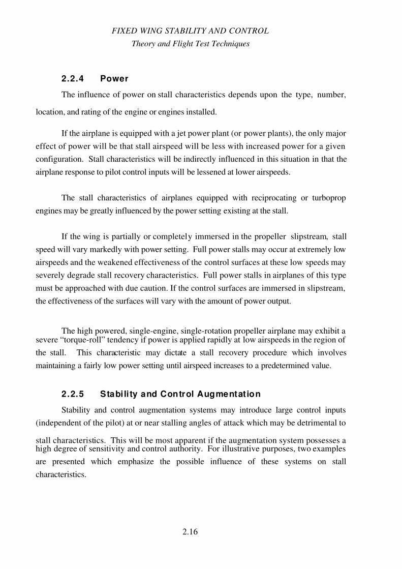
2.2.4 Power
The influence of power on stall characteristics depends upon the type, number,
location, and rating of the engine or engines installed.
If the airplane is equipped with a jet power plant (or power plants), the only major
effect of power will be that stall airspeed will be less with increased power for a given
configuration. Stall characteristics will be indirectly influenced in this situation in that the
airplane response to pilot control inputs will be lessened at lower airspeeds.
The stall characteristics of airplanes equipped with reciprocating or turboprop
engines may be greatly influenced by the power setting existing at the stall.
If the wing is partially or completely immersed in the propeller slipstream, stall
speed will vary markedly with power setting. Full power stalls may occur at extremely low
airspeeds and the weakened effectiveness of the control surfaces at these low speeds may
severely degrade stall recovery characteristics. Full power stalls in airplanes of this type
must be approached with due caution. If the control surfaces are immersed in slipstream,
the effectiveness of the surfaces will vary with the amount of power output.
The high powered, single-engine, single-rotation propeller airplane may exhibit asevere “torque-roll” tendency if power is applied rapidly at low airspeeds in the region of
the stall. This characteristic may dictate a stall recovery procedure which involves
maintaining a fairly low power setting until airspeed increases to a predetermined value.
2.2.5 Stabili ty and Control Augmentation
Stability and control augmentation systems may introduce large control inputs
(independent of the pilot) at or near stalling angles of attack which may be detrimental to
stall characteristics. This will be most apparent if the augmentation system possesses ahigh degree of sensitivity and control authority. For illustrative purposes, two examples
are presented which emphasize the possible influence of these systems on stall
characteristics.

7/15/2019 FTM103-chapter2-stalls.pdf
http://slidepdf.com/reader/full/ftm103-chapter2-stallspdf 22/49
STALLS
2.17
The first example is extracted from accelerated stall tests of a light jet attack airplane
equipped with longitudinal and lateral control augmentation and directional stability
augmentation. The time history of an accelerated stall which was aggravated by the roll
damper mode of the control augmentation system is shown in Figure 2.10. The stall was
entered from a left turn with 2g normal acceleration; approach to the stall was characterizedby increasing airframe buffet. Just prior to the stall (at 8 seconds on the time history), note
that the pilot was required to hold right aileron position to keep the airplane from entering a
tighter left turn. The stall was marked by a “directional slice” to the left, at which time the
pilot neutralized the controls (at 10 seconds on the time history). At this time, the roll
damper portion of the control augmentation mode, sensing a left roll rate without a pilot
control input, applied a large right lateral control input. Note that the cockpit control stick
was essentially neutra l at this time. The aileron input of the roll damper was in the pro-spin
direction and the airplane entered a left spin. After approximately two turns of the spin, the
pilot deactivated control augmentation and effected recovery by applying aileron into the
spin, rudder against the spin, and full aft longitudinal control.
The second example is extracted from normal stall tests of a twin-engine turboprop
transport airplane equipped with directional stability augmentation. This augmentation
system was composed of yaw damping, directional trim follow-up, and a turn coordination
feature. The time history of a normal stall (Power approach configuration) which was
aggravated by the turn coordination feature of the stability augmentation system is shown in
Figure 2.11. Power approach configuration stalls in this airplane were characterized byabrupt rolls (note the bank angle change at the stall). The turn coordination feature of the
stability augmentation sensed the rolling motion and attempted to coordinate with a large
left rudder input. Note that about 10 degrees of left rudder deflection was introduced by
the stability augmentation system while the pilot was holding right rudder pedal deflection.
The large left rudder input increased the left bank angle and sideslip excursions and the
airplane entered a series of uncontrollable snaprolls. Recovery was initiated by deactivating
stability augmentation. During the recovery, airspeed and normal acceleration limitation of
the airframe were exceeded.

7/15/2019 FTM103-chapter2-stalls.pdf
http://slidepdf.com/reader/full/ftm103-chapter2-stallspdf 23/49
FIXED WING STABILITY AND CONTROL
Theory and Flight Test Techniques
2.18
Configuration: Power (Mil Thrust) CG: 26.5% MACLoading: Normal Attack Gross Wt: 28,490 LBAltitude at Stall: 28,000 FT Yaw Stab: OnAirspeed at Stall: 200 KIAS Control Aug: On
+3
+2
+1
0
-1
Stall
N O R M A L
A C C E
L E R A T I O N
g
50
0
50
N U
N D
100
D E G
P I T C H
A T T I T U D E
10
0
10
20
R T
L F T D E G
L A T E R A L
S T I C K
P O S I T I O N
20
0
20
Input by Roll Damper
Control Aug Off
T E U
T E D D
E G
L E F T
A I L E R O N
P O I S T I O N
200 R W D
100
0
100
200
D E G
L W D R
O L L
A T T I T U D E
D E G R T
L F T
20
0
20
R U D D E R
P E D
A L
P O S I T I O N
20
0
20
T E L
T E R D
E G
R U D D E R
P O S I T I O N
R T
L F T
10
0
10
20
30
D E G / S E C
0 4 8 12 16 20 24 28 32
TIME ~ SEC
Y A W
R A T E
Figure 2.10Accelerated Stall Time History

7/15/2019 FTM103-chapter2-stalls.pdf
http://slidepdf.com/reader/full/ftm103-chapter2-stallspdf 24/49
STALLS
2.19
Configuration: Power Approach CG: 33.6% MACAltitude at Stall: 10,000 FT Gross Wt: 45,900 LBAirspeed at Stall: 80 KIAS Stab Aug: On
+4
+2
0
-2
N O
R M A L
A C C E L
E R A T I O N
g
30
0
30
A N U
A N D D
E G
A N G L E
O F
P I T C H
+40
0
-40
D E G
A N G L E
O F
A T T A C K
4
2
0
2
R T
I N C H
L F T
R U D D E
R
P E D A L
P O S I T I O N
4
Stab Aug Introduces Left Rudder Input20
10
0
10
20
T E R
T E L
Stab Aug Off
R U D D E R
P O S I T I O N
R T25
0
25 L F T
D E G
S I D E S L I P
20
0
20
R T
L F T D E G
L A T E R A L
W H E E L
P O S I T I O N
80
40
0
40
80
R T
L F T
D E G
0 4 8 12 16 20 24 28 32
B A N K
A N G L E
Stall
TIME ~ SEC
Figure 2.11Normal Stall Time History

7/15/2019 FTM103-chapter2-stalls.pdf
http://slidepdf.com/reader/full/ftm103-chapter2-stallspdf 25/49
FIXED WING STABILITY AND CONTROL
Theory and Flight Test Techniques
2.20
It should be emphasized that stability and control augmentation systems do not
always degrade stall characteristics. Some systems may have no influence; other systems
may have significant influence on airplane behavior in the region of the stall. Knowledge
of the various modes and functions and the control authority of the augmentation system in
the airplane being tested is essential if the stall investigation is to be conducted rigorously
and safely.
2 .2 .6 Miscellaneous Factors
Additional factors influencing the behavior of the airplane in the region of the stall
are listed below.
1. Location of Control Surfaces - If the control surfaces are immersed in low
energy separated airflow at the stall, the controllability of the airplane will be
decreased. The lateral control surfaces are particularly susceptible to immersion
in separated flow.
2. Configuration . The extension of wing flaps, wing leading edge slats, speed
brakes, landing gear, etc., will have some influence on stall characteristics.
This influence may be estimated by consideration of the location of various
devices in relation to control surfaces and stabilizers. Some configuration
changes, such as flap extension, may result in airframe buffet which masks theprestall aerodynamic buffett, decreasing its value as a stall warning.
3. External Stores . Stall characteristics may be altered by various combinations of
external stores. Asymmetric store loadings may severely degrade stall
characteristics, particularly during accelerated entries. The investigation of stall
characteristics under asymmetric loading conditions should be accomplished on
any airplane which may carry asymmetric loads in operational use.
4. Center of Gravity . Stall characteristics may be markedly influenced by airplane
center of gravity (CG) if the airplane exhibits a deficiency in longitudinal control
effectiveness. At forward CG positions in some airplanes, nose-up longitudinal
control effectiveness may not be sufficient to attain maximum lift coefficient.
The minimum attainable airspeeds for these airplanes would be marked by
steady flight with full nose-up longitudinal control; minimum attainable speed

7/15/2019 FTM103-chapter2-stalls.pdf
http://slidepdf.com/reader/full/ftm103-chapter2-stallspdf 26/49
STALLS
2.21
would, of course, vary with CG position, decreasing as the CG moves aft. At
aft CG positions in other airplanes, nose-down longitudinal control
effectiveness may not be sufficient to quickly reduce angle of attack after
attaining the stall. This situation would seriously compromise, and might
preclude, stall recovery.
5. Shock-Induced Separation . Shock-induced separation or a “shock stall” may
cause the stall to occur at a lower angle of attack than might be predicted
through incompressible flow considerations. Tendencies toward shock-induced
separation would, of course, increase with increasing subsonic airplane Mach
number; however, shock stalls can occur at Mach numbers well below the
“normal transonic region.” The phenomenon of shock-induced separation may
be particularly evident during accelerated stalls.
2.2.7 Characteristics Which May Limit Minimum Steady
Airspeed
For some airplanes, the attainment of maximum lift coefficient may not be possible
or feasible. This may be caused by a loss of directional control without a reduction of lift,
lack of longitudinal control effectiveness, or an extremely large increase in drag coefficient.
2.2.7.1 LOSS OF CONTROL WITHOUT REDUCTION OF LIFT
During approaches to normal or accelerated stalls, directional stability may be
reduced significantly through the deterioration of airflow around the vertical stabilizer. At
high angles of attack, the vertical tail may become immersed in nonstreamlined, low energy
flow generated by flow separation on the wing and interference effects from aft-fuselage
mounted engines, speedbrakes, or other protrusions (Figure 2.12).
Figure 2.12Typical Flow Pattern Around the Vertical Tail
at High Angle of Attack

7/15/2019 FTM103-chapter2-stalls.pdf
http://slidepdf.com/reader/full/ftm103-chapter2-stallspdf 27/49
FIXED WING STABILITY AND CONTROL
Theory and Flight Test Techniques
2.22
The deterioration in effectiveness of the vertical tail generally results in increasing
yaw excursions with increases in angle of attack. The airplane may diverge directionally
prior to attaining maximum lift coefficient if the destabilizing action progresses sufficiently.
Directional divergence can be “triggered” or aggravated by lateral control inputs if these
control inputs generate significant yawing moments. High angle of attack directional
divergence is sometimes referred to as “slicing” and would limit minimum steady airspeed
and preclude attainment of the maximum lift coefficient.
2.2.7.2 LACK OF LONGITUDINAL CONTROL EFFECTIVENESS
The longitudinal control surfaces on some airplanes may not be sufficiently
effective to rotate the airplane to the angle of attack corresponding to maximum lift
coefficient. These airplanes are sometimes referred to as “elevator-limited” airplanes.
Minimum steady airspeed or maximum angle of attack in this situation is that which is
attained with full nose-up longitudinal control. Since elevator effectiveness is a function of
center of gravity (CG) position, stalling airspeed and angle of attack for these airplanes will
vary with CG position.
2.2.7.3 “ZERO RATE OF CLIMB SPEED”
The very low aspect ratio (less than two) airplane exhibits practically no
aerodynamic stall; however, its minimum practical airspeed will be limited by performance
considerations, if not by adverse stability and control characteristics. The variation of lift
and drag coefficients for the low aspect ratio or “slender delta” design gives insight into the
problem which may exist (Figure 2.13).

7/15/2019 FTM103-chapter2-stalls.pdf
http://slidepdf.com/reader/full/ftm103-chapter2-stallspdf 28/49
STALLS
2.23
While the lift curve exhibits no definite peak which would define maximum lift
coefficient, the drag curve may exhibit a tendency to slope upward sharply at high angles of
attack. An angle of attack, corresponding to an airspeed, would be attained at which the
airplane could not maintain a rate of climb with maximum engine power. This airspeed is
defined as the “zero rate of climb speed” (ZRCS). Of course, it will change with
configuration, altitude, engine output, and gross weight. The only hazard directly
associated with flight at airspeeds less than ZRCS is loss of performance . For example, if an airplane decelerates below ZRCS during the approach, a sacrifice in altitude (possibly a
significant one) must be made in order to execute a wave-off. A disturbing feature of an
airplane capable of steady flight at airspeeds below that at which it has sufficient power to
maintain level flight is the long “settling time” needed to establish a final flight path. For
instance, it may be possible to fly at speeds slightly below ZRCS with a slight rate of climb
for periods as long as 1 minute. The slight rate of climb is caused by the inertia of the
airplane as is settles down on its final flight path. The pilot might deduce that he is above
ZRCS due to this phenomenon. However, he eventually finds that the airplane begins a
shallow descent. Increasing angle of attack at this stage only increases the rate of descent
and some height must be sacrificed for recovery. Recovery from airspeeds below ZRCS
can only be accomplished by pushing the nose over to decrease angle of attack, then
reestablishing a climb at an airspeed above ZRCS.
L i f t C o e f f i c
i e n t
C L
Angle of Attack
α
D r a g C o e f f i
c i e n t
C D
++
+
CL
CD
Figure 2.13Typical Variations of Lift and Drag Coefficient
for the Low Aspect Ratio Airplane

7/15/2019 FTM103-chapter2-stalls.pdf
http://slidepdf.com/reader/full/ftm103-chapter2-stallspdf 29/49
FIXED WING STABILITY AND CONTROL
Theory and Flight Test Techniques
2.24
For some airplanes, “zero rate of climb speed” may constitute the extreme limit of
safe flight, and operational speeds must be chosen which provide adequate margins against
accidental exposure to irrecoverable situations.
NOTE: It must be emphasized the ZRCS is expected to limit minimum airspeed
only for airplanes with very low aspect ratio and very slender wing designs. During stall
investigations of any airplane, certain flight conditions will be encountered where the
airplane will be descending at significant rates, such as landing configuration with idle
power or power on stalls at high altitude. However, the high rate of descent does not
necessarily indicate a minimum airspeed limit above aerodynamic stalling airspeed and
should not be reported as such. Whenever safety considerations/risk management permit,
the stall investigation should probe into the stall region as deeply as possible.
2.2.8 Stall Warning and Stall Prevention Devices
2.2.8.1 ARTIFICIAL STALL WARNING
Airplanes which do not exhibit adequate aerodynamic stall warning, such as
airframe buffet, are frequently equipped with devices which detect the approach of the stall
and transmit a warning to the pilot. Artificial stall warning is, at best, a poor substitute for
aerodynamic stall warning since the detection device is never absolutely reliable.
Any artificial stall warning system should satisfy the following requirements:
1. The system should be capable of stall warning for any airplane configuration,
airspeed, altitude, normal accelerations, sideslip, bank angle, and power
setting. In addition, the system should not be susceptible to atmospheric
influence, such as temperature and pressure variations, precipitation, and icing.
2. The warning provided the pilot should be unmistakable and sufficiently inadvance of the stall to allow avoidance of the stall without undue pilot effort.
3. The system should be easy to maintain and easy to calibrate on the ground.

7/15/2019 FTM103-chapter2-stalls.pdf
http://slidepdf.com/reader/full/ftm103-chapter2-stallspdf 30/49
STALLS
2.25
Some of the devices used to detect approach of the stall and their principle of
operation are listed below.
Table 2.I
Summary of Stall Warning Devices
Device Principle of Operation
Free Floating Probe or Vane Airflow direction (angle of attack)
Drag Sensing Probe Airflow direction (angle of attack)
Differential Pressure Head Airflow direction (quantity proportional to
angle of attack)
Null Pressure Probe Airflow direction (angle of attack)
Leading Edge Tab Wing dynamic pressure
Trailing Edge Tab Wing dynamic pressure
Trailing Edge Pitot Tube Wing dynamic pressure
Pitot Tube with Local Spoiler Wing dynamic pressure
Flush-Mounted Wing Port Static pressure at wing surface
Trailing Edge “Blister” Static pressure at wing surface
Boundary Layer Pitot Tube Boundary layer pressure fluctuation
The means by which the pilot is warned of the approaching stall may be visual
(warning light), oral (sound in earphones), or physical (shaking or vibrating of rudder
pedals or control stick). The most suitable artificial forms of cockpit warning are probably
the “stick shaker” and vibrating stick grip; these warning signals are similar to aerodynamic
buffeting of the controls and are difficult to misinterpret.
2.2.8.2 ARTIFICIAL OR AUTOMATIC STALL PREVENTION
For some airplanes, particularly large transport and passenger types, stalling
maneuvers may be structurally or aerodynamically unsafe. In order to guarantee adequate
flight safety even under abnormal flight conditions, such as strong, sudden pull-ups or
abrupt longitudinal attitude changes caused by gusts, these airplanes may be equipped with
a “stall prevention” system. Stall prevention systems are used quite commonly in “T-tail”
airplanes.

7/15/2019 FTM103-chapter2-stalls.pdf
http://slidepdf.com/reader/full/ftm103-chapter2-stallspdf 31/49
FIXED WING STABILITY AND CONTROL
Theory and Flight Test Techniques
2.26
Any artificial stall prevention system should satisfy the following requirements:
1. The system should be capable of stall prevention for any airplane configuration,
airspeed, altitude, normal acceleration, sideslip, bank angle, and power setting.
The system should not be susceptible to atmospheric influence, such as
temperature or pressure variations, precipitation, and icing.
2. The system should provide a large nose-down pitching moment at the stall or
just after the stall; however, the pilot should be able to “override” the system if
he desires. The “override” force should be large enough to discourage
inadvertent “override” and associated “deep-stall” penetration.
3. Inadvertent operation of the system should not lead to dangerous flightconditions. This is particularly applicable to the take-off and landing
evolutions.
4. The system should be easy to maintain and easy to calibrate on the ground.
A commonly used stall prevention device is a “stick pusher” arrangement which is
activated through a signal from an angle of attack or pressure sensor.
No matter how well-designed and how reliable it may be, a stall prevention system
represents added complexity in the airplane. Unless safety or overriding design
considerations dictate otherwise, stall prevention systems should be avoided.
2 .3 TEST PROCEDURES AND TECHNIQUES
2 .3 .1 Preflight Procedures
Successful stall investigations can be accomplished only after thorough preflightplanning. During preflight planing, the purpose and scope of the tests must be clearly
defined. After purpose and scope are clearly understood, a “plan of attack” or test method
can be formulated.

7/15/2019 FTM103-chapter2-stalls.pdf
http://slidepdf.com/reader/full/ftm103-chapter2-stallspdf 32/49
STALLS
2.27
Preflight planing should start with research . This includes a study of the airplane -
many stall characteristics can be predicated by studying various design parameters of the
airplane. All available information on stall characteristics should be reviewed. Much
useful information may be gained by conversations with pilots and engineers familiar with
the airplane.
The test conditions - altitude, configuration, center of gravity, and trim airspeeds -
must be determined. Test conditions should be commensurate, as much as possible, with
the mission environment of the airplane. However, safety considerations/risk management
dictate that investigations of stall characteristics be performed in such a manner that the
most critical conditions are tested only after a reasonable build-up program. Altitude at stall
entry should never be lower than 10,000 feet above ground level; however, a higher
minimum altitude may be used if unusual characteristics are expected. Although center of
gravity (CG) position may affect both the stall and the recovery, tests at the most forward
and most aft operational CG positions are generally adequate. However, if a lack of nose-
down longitudinal control or “pitch-up” at high angles of attack are suspected, forward CG
positions should be used for initial investigations. Because of possible adverse stall
characteristics resulting from high power settings and extension or activation of high-lift
devices, a “clean” airplane configuration with low engine power settings should be chosen
for initial stall tests. Appropriate trim airspeeds should be chosen for each configuration to
be evaluated. For example, appropriate trim conditions for an investigation of power
approach configuration stalls would be those corresponding to normal approach airspeedand angle of attack. Of course, the effects of “trimming” into the stall and “out of trim”
entries into the stall should be determined also.
The amount and sophistication of instrumentation required will depend on the
purpose and scope of the evaluation. A pure qualitative investigation can be accomplished
with only cockpit and hand-held instruments. A portable tape recorder for pilot comments
is especially useful. If accurate quantitative information is needed, or if preliminary studies
indicate very adverse stall characteristics, automatic recording devices, such as
oscillograph, photopanel, and telemetry, should be utilized. The parameters to be recorded
and ranges and sensitivity of test instrumentation will vary somewhat with each test
program.

7/15/2019 FTM103-chapter2-stalls.pdf
http://slidepdf.com/reader/full/ftm103-chapter2-stallspdf 33/49
FIXED WING STABILITY AND CONTROL
Theory and Flight Test Techniques
2.28
The final step in preflight planning is the preparation of pilot data cards. An
example of a stall data card is presented in Figure 2.14. However, most test pilots desire to
modify data cards to their own needs or construct data cards for each test. At any rate, the
data cards should list all quantitative information desired and should be easy to interpret in
flight. For stall investigations in particular, several data cards with adequate space for pilot
comments should be provided.

7/15/2019 FTM103-chapter2-stalls.pdf
http://slidepdf.com/reader/full/ftm103-chapter2-stallspdf 34/49
STALLS
2.29
WEATHER CARD NO.
PIR RIS
AIRPLANE TYPE TIME T. O.
TIME LAND
DATE
PILOT
BU NO
T O C G
GEAR DOWN % UP %
CONDITION T. O. GROS WT.
EXTERNAL CONFIGURATION
TEST
CONFIGURATION
TEST
ALTITUDE
TRIM SPEED
TRIM TABS
POWER
FUEL QUANTITY
BUFFET
CONTROL EFFECTIVENESS
CONTROL FORCES
LONG STICK POSITION
BUFFET
ROLL
PITCH
CONTROL EFFECTIVENESS
CONTROL FORCES
ALT. LOST
CONTROL EFFECTIVENESS
CONTROL FORCES
PROGRESSIVE STALL TENDENCIES
STALL DATA PRNC-NATC-3900/4 GPO 929-452
WRN
A P P R O A C H
S T A L L
R E C O V E R Y
Figure 2.14Typical Stall Data Card
7/15/2019 FTM103-chapter2-stalls.pdf
http://slidepdf.com/reader/full/ftm103-chapter2-stallspdf 35/49
FIXED WING STABILITY AND CONTROL
Theory and Flight Test Techniques
2.30
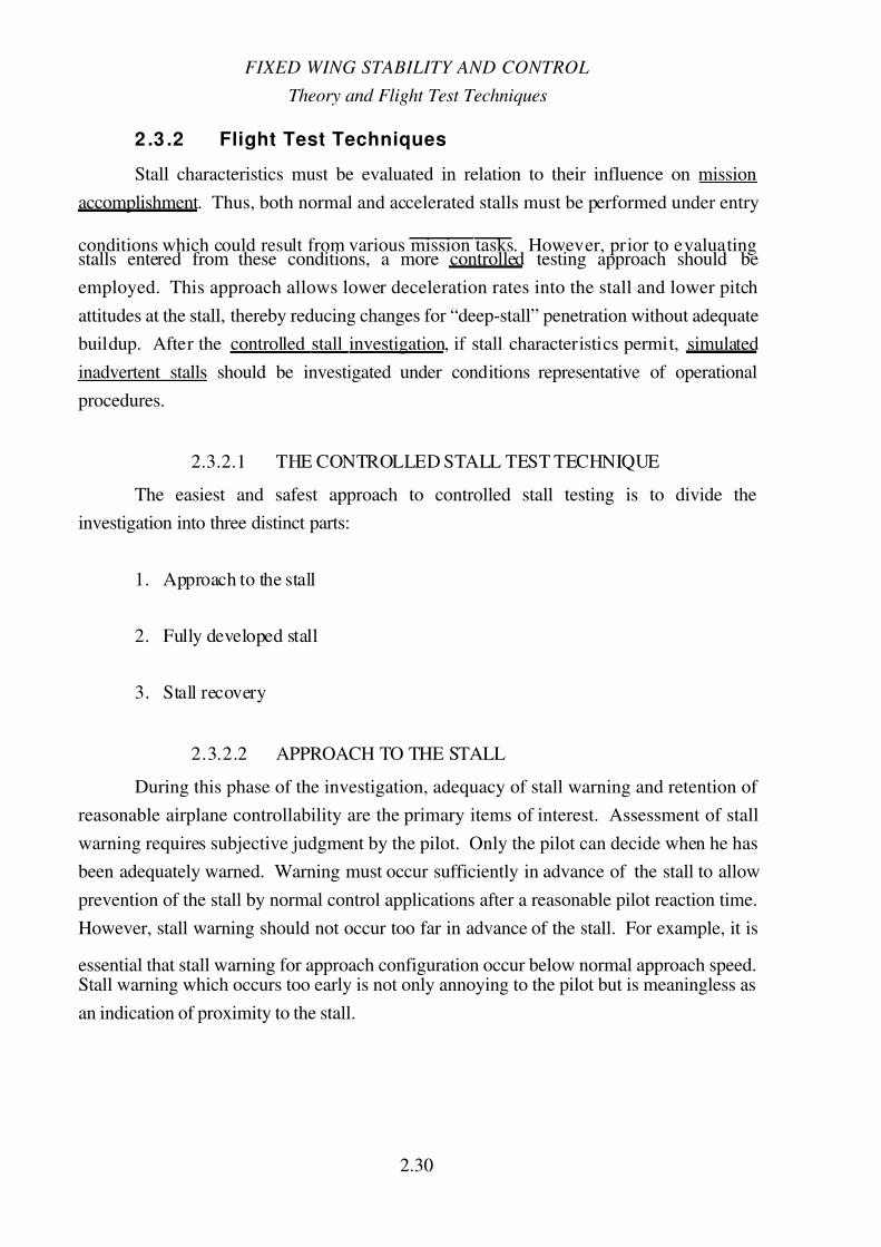
2 .3 .2 Flight Test Techniques
Stall characteristics must be evaluated in relation to their influence on mission
accomplishment. Thus, both normal and accelerated stalls must be performed under entry
conditions which could result from various mission tasks . However, prior to evaluatingstalls entered from these conditions, a more controlled testing approach should be
employed. This approach allows lower deceleration rates into the stall and lower pitch
attitudes at the stall, thereby reducing changes for “deep-stall” penetration without adequate
buildup. After the controlled stall investigation , if stall characteristics permit, simulated
inadvertent stalls should be investigated under conditions representative of operational
procedures.
2.3.2.1 THE CONTROLLED STALL TEST TECHNIQUE
The easiest and safest approach to controlled stall testing is to divide the
investigation into three distinct parts:
1. Approach to the stall
2. Fully developed stall
3. Stall recovery
2.3.2.2 APPROACH TO THE STALL
During this phase of the investigation, adequacy of stall warning and retention of
reasonable airplane controllability are the primary items of interest. Assessment of stall
warning requires subjective judgment by the pilot. Only the pilot can decide when he has
been adequately warned. Warning must occur sufficiently in advance of the stall to allow
prevention of the stall by normal control applications after a reasonable pilot reaction time.
However, stall warning should not occur too far in advance of the stall. For example, it is
essential that stall warning for approach configuration occur below normal approach speed.Stall warning which occurs too early is not only annoying to the pilot but is meaningless as
an indication of proximity to the stall.

7/15/2019 FTM103-chapter2-stalls.pdf
http://slidepdf.com/reader/full/ftm103-chapter2-stallspdf 36/49
STALLS
2.31
The type of stall warning is very important. Primary stall warning is generally in
the form of airframe buffet, control shaking, or small amplitude airplane oscillations in roll,
yaw, or pitch. Other secondary cues to the approach to the stall may be high pitch attitude,
large longitudinal control pull forces (of course, this cue can be destroyed by “trimming
into the stall”), large control deflections, or sluggish control response. In any case, stallwarning, whether natural or artificial, should be unmistakable, even under conditions of
high pilot workload and stress and under conditions of atmospheric turbulence. If an
artificial stall warning device is installed, approach to the stall should be evaluated with the
device operative and inoperative to determine if the device is really required for normal
operations.
During this phase of the evaluation, the test pilot must evaluate stall warning with
the intended use and operational environment in mind. He must remember that he is
specifically looking for the stall warning under controlled conditions. The operational pilot
probably will not be. This question must be answered: will the operational pilot,
preoccupied by other tasks and not concentrating on stalls, recognize approach of the stall
and be able to prevent the stall?
The general flying qualities of the airplane should be investigated during the
approach to the stall as well as stall warning characteristics. Longitudinal, lateral, and
directional control effectiveness for maintaining a desired attitude may deteriorate
significantly during the approach to the stall. Loss of control about any axis such asuncontrollable pitch-up or pitch-down, “wing drop,” or directional “slicing” may define the
actual stall. During the approach to the stall, the test pilot should be particularly aware of
the amount of longitudinal nose-down control available because of the obvious influence of
this characteristic on the ability to “break” the stalled condition and make a successful
recovery.
This phase of stall investigation usually begins with onset of stall warning and ends
at the stall; therefore, the test pilot will certainly be concerned with the manner in which the
airplane stalls and the ease of recovery. However, primary emphasis is placed on obtaining
an accurate assessment of stall warning and general flying qualities during the approach to
the stall. During initial investigations, it may be prudent to terminate the approach short of
the actual stall, penetrating deeper and deeper with each succeeding approach until limiting
conditions or the actual stall are reached. In addition, the rate of approach should be low
initially, less than 1 knot per second for normal stalls. Investigations of accelerated stalls

7/15/2019 FTM103-chapter2-stalls.pdf
http://slidepdf.com/reader/full/ftm103-chapter2-stallspdf 37/49
FIXED WING STABILITY AND CONTROL
Theory and Flight Test Techniques
2.32
should be made by using the “constant normal acceleration” technique or the “constant
airspeed” technique. The constant normal acceleration technique is performed by selecting
and holding a desired g level while allowing the airplane to decelerate until the stall is
encountered. Slow deceleration rates (typically 2 knots/second) are used for initial
investigations. As experience is gained, faster deceleration rates should be performed
unless safety considerations dictate otherwise. The constant airspeed technique will be
discussed in the STALL TEST TECHNIQUE S section.
The test pilot should record at least the following cockpit data during the approach
to the stall:
1. Airspeed and angle of attack at stall warning.
2. Type and adequacy of stall warning.
3. Longitudinal control force at stall warning (either measured or estimated).
4. Qualitative comments regarding controllability and control effectiveness.
2.3.2.3 FULLY DEVELOPED STALL
During this phase of the investigation, the primary objective is to accurately definethe stall and the associated airplane behavior. The stall should be well-marked by some
characteristic, such as pitch-up or pitch-down or lateral or directional divergence. In
general, any pitch-up or directional divergence at the stall is undesirable because pitch-up
may precipitate a deep stall penetration and directional divergence may lead to a spin.
Pitch-down at the stall and lateral divergence may be acceptable; however, severe rolling,
pitching, or yawing or any combination of the three are obviously poor characteristics.
Control effectiveness as evidenced by the pilot's ability to control or induce roll,
pitch, or yaw should be evaluated in the stall, if airplane behavior permits this to be done
safely . Obviously, control effectiveness should be evaluated with a suitable build-up
program. Initially, control inputs only large enough to effect an immediate coordinated
recovery should be used. As experience is gained, the airplane should be maintained in the
stalled condition for longer and longer periods of time, and the effectiveness of all controls
evaluated with larger and larger control deflections.

7/15/2019 FTM103-chapter2-stalls.pdf
http://slidepdf.com/reader/full/ftm103-chapter2-stallspdf 38/49
STALLS
2.33
The test pilot should record at least the following cockpit data regarding the stall:
1. Airspeed and angle of attack at stall.
2. Load factor (accelerated stalls only).
3. Characteristic which defines the stall.
4. Longitudinal control force at the stall (either measured or estimated). The ratio
of longitudinal control forces at stall and stall warning is a rough indication of
longitudinal stability in the high angle of attack region and an indication of the
ease of inadvertent stalling.
5. Qualitative descriptive comments.
2.3.2.4 STALL RECOVERY
During this phase of the investigation, primary items of interest are the ease of
recovery (the pilot's task), general flying qualities during the recovery, altitude required for
recovery, and the determination of an optimum recovery technique. The definition of stall
recovery may vary with the configuration under investigation. For example, the goal of
recovery for configurations commensurate with combat maneuvering may be to regain
sufficient control effectiveness about all three axes to perform offensive or defensive
maneuvering tasks; the attainment of level flight may not be critical in these configurations.
The goal of recovery for take-off and approach configurations should be the attainment of
level flight with a minimum loss of altitude and the regaining of sufficient control
effectiveness to safely maintain stall-free conditions. In each case, the test pilot must
clearly define “stall recovery.”
During initial investigation, the stall recovery procedures specified in pertinentpublications should be utilized and the ease of effecting recovery evaluated. If no
procedure has been developed, initial recovery must be accomplished with a preliminary
technique formulated from all available technical information. As experience is gained,
various modifications to the recovery procedure should be made until an optimum
procedure is determined. In arriving at an optimum procedure for use by the operational

7/15/2019 FTM103-chapter2-stalls.pdf
http://slidepdf.com/reader/full/ftm103-chapter2-stallspdf 39/49
FIXED WING STABILITY AND CONTROL
Theory and Flight Test Techniques
2.34
pilot, the test pilot must not only consider the effectiveness of the technique (in terms of
altitude loss or maneuverability regained) but must also consider the simplicity of the
technique.
The test pilot should record at least the following data regarding stall recovery:
1. Qualitative comments on ease of recovery
2. Optimum recovery technique
3. Altitude loss in recovery
4. Qualitative comments on control effectiveness
2.3.2.5 PROFILE OF THE CONTROLLED STALL TEST
TECHNIQUE
The general flight profile of the controlled stall investigation is presented in Figure
2.15. Points along the profile are further explained on the following page. It should be
remembered that until familiarity with stall behavior of the airplane is gained, the profile
may be broken off at any point.
A
BC
D
CB
EF
Entry
Approach
Test Altitude
EntryApproach
Stall
RecoverySituation Review
Trim
Figure 2.15General Profile of the Controlled Stall Investigation

7/15/2019 FTM103-chapter2-stalls.pdf
http://slidepdf.com/reader/full/ftm103-chapter2-stallspdf 40/49
STALLS
2.35
A. Trim Point. The configuration under investigation should be established.
At least the following items should be recorded in the cockpit:
1. Trim speed
2. Trim tab setting
3. Power setting
4. Fuel quantity
If automatic recording devices are installed, a “trim shot” should be made.
B. Entry Point. Decide on an entry point which will result in the stall occurring
near the test altitude (+1000 feet). The entry procedures will be different for normal and
accelerated stall investigations.
Normal Stalls . Slow the airplane rapidly to about 20 KIAS above the estimated
stall warning speed. Power reduction or speed brake extension may be utilized.
Reestablish trim configuration at this new airspeed . Make a slight pitch increase to start the
deceleration toward the stall. Using the visual horizon as a primary cue and airspeed
indicator as a crosscheck, establish the desired deceleration rate. Deceleration rate shouldbe one knot per second or less initially, but may be increased as experience is gained.
Accelerated Stalls . For initial investigations, the constant normal acceleration
technique is normally used. Select an entry normal acceleration commensurate with
configuration, flight conditions, and familiarity with the accelerated stall characteristics. If
appropriate and feasible, slow the airplane to about 40 KIAS above the estimated stall
warning speed for the selected load factor. Entry normal acceleration should be increased
to maximum allowable or attainable as familiarity is gained. Establish a roughly level turn
at entry normal acceleration. Maintaining normal acceleration constant, establish the
desired deceleration rate. The primary reference should be the visual horizon, although the
normal accelerometer, angle of attack indicator, and airspeed indicator will have to be
crosschecked frequently. Deceleration rate should be approximately 2 knots per second or
less initially, but may be increased as experience is gained.

7/15/2019 FTM103-chapter2-stalls.pdf
http://slidepdf.com/reader/full/ftm103-chapter2-stallspdf 41/49
FIXED WING STABILITY AND CONTROL
Theory and Flight Test Techniques
2.36
C. Approach to the Stall. If automatic recording devices are utilized, they
should be activated at some convenient point prior to stall warning. The event marker may
be used to mark stall warning on the recording traces. In order to aid in remembering data,
the pilot should call out the airspeed and angle of attack at stall warning onset and mentally
note the type and adequacy of the warning. For approaches to normal stalls, utilize pitch
control to maintain 1.0 g normal acceleration and the predetermined deceleration rate.
During approaches to accelerated stalls, a combination of bank angle and pitch attitude are
used to maintain normal acceleration and deceleration rates at predetermined values. An
increase in bank angle will slow the deceleration rate and a decrease in bank angle will
speed it up, providing the normal acceleration is maintained constant.
D. The Stall. There is a natural tendency to relax nose-up longitudinal control
as the stall is approached in unaccelerated or accelerated entries. This tendency should beovercome by maintaining deceleration rate and normal acceleration into the stall with
positive pitch attitude control. If the stall is marked by pitch-down, pitch attitude and
normal acceleration should be closely monitored for accurate detection of the stall. At the
stall, actuate the event marker if automatic recording devices are used and call out the
airspeed, angle of attack, and altitude at the stall. Mentally note the airplane behavior at the
stall and initiate recovery control inputs and configuration changes.
E. The Recovery. Follow the predetermined recovery procedure and effect
recovery. Qualitatively evaluate recovery characteristics. Call out final recovery altitude
and actuate the event marker if utilized. The automatic recording devices should be
deactivated when convenient.
F. The Situation Review. As the airplane is started toward the next stall test
point, the pilot should record at least the following cockpit data from the last stall:
1. Stall warning speed and angle of attack
2. Type and adequacy of stall warning
3. Stall speed and angle of attack
4. Stall characteristics

7/15/2019 FTM103-chapter2-stalls.pdf
http://slidepdf.com/reader/full/ftm103-chapter2-stallspdf 42/49
STALLS
2.37
5. Recovery characteristics
6. Altitude lost and airspeed buildup during recovery
2.3.2.6 ALTERNATE TECHNIQUE FOR ACCELERATED STALL
INVESTIGATIONS
It is recommended that initial accelerated stall tests be performed utilizing the
“constant normal acceleration” technique described above; this technique allows a gradual
build-up to accelerated stalls at high levels of normal acceleration. After experience is
gained in the accelerated stall characteristics of the airplane, the wind-up turn or “constant
airspeed” technique may be utilized; this technique is more expeditious and somewhat
simulates inadvertent stalls in operational use. The technique merely involves graduallyincreasing angle of attack or normal acceleration at constant airspeed or Mach number in a
wind-up turn until the airplane stalls. The difference between the angle of attack or normal
acceleration at stall warning onset and at stall is an additional measure of the adequacy of
the stall warning.
2.3.2.7 SIMULATED INADVERTENT STALLS
If the results of the controlled stall investigation indicate that inadvertent stalls will
produce no dangerous flight conditions, simulated inadvertent stalls should be investigated
from entry conditions which could result from various operational procedures. These entry
conditions will generally involve more rapid deceleration rates during normal stalls and
more rapid increases in normal acceleration during accelerated stalls.
The mission tasks most likely to result in inadvertent stalls should be used as entry
conditions. These mission tasks may be those required in air combat maneuvering,
gunnery exercises, missile attacks and reattacks, and conventional and nuclear weapons
deliveries. Other tasks peculiar to take-off and approach conditions must also be used as
entry conditions; these may include simulated catapult launches, field take-offs, wave-offs,or “bolters,” and field or carrier approaches. Of course, the mission tasks will vary widely
in all test programs; these are presented as examples for illustration. No matter what tasks
are selected, all stalls should be performed at a safe altitude (at least 10,000 feet).

7/15/2019 FTM103-chapter2-stalls.pdf
http://slidepdf.com/reader/full/ftm103-chapter2-stallspdf 43/49
FIXED WING STABILITY AND CONTROL
Theory and Flight Test Techniques
2.38
By performing simulated inadvertent stalls under conditions representative of
operational procedure, more complete knowledge is gained of the adequacy of stall
warning, the characteristics of the actual stall, and the ease of recovery from the stall. No
rigorous stall investigation would be complete without this type of evaluation.
2 .3 .3 Postflight Procedures
As soon as possible after returning from the flight, the test pilot should write a
brief, rough qualitative report of the airplane behavior in the region of the stall. This report
should be written while the events of the flight are fresh in his mind. The qualitative
opinion will be the most important part of the final report of the stall characteristics.
Appropriate data should be selected to substantiate the pilot's opinion. If automatic
recording devices have been utilized, stall time histories will be presented in the stall report.
The time histories should be of particularly well flown stalls, or of stalls during which
some unusual characteristics were observed. Examples of stall time histories are presented
earlier in this section (Figure 2.10 and 2.11). Stall data also may be effectively presented
in tabular form. An example is presented in Figure 2.16.

7/15/2019 FTM103-chapter2-stalls.pdf
http://slidepdf.com/reader/full/ftm103-chapter2-stallspdf 44/49
STALLS
2.39
2 .4 SPECIFICATION REQUIREMENTS
Requirements for stall characteristics are contained in Section 3.4.2 of Military
Specification MIL-F-8785C of 5 November 1980, hereafter referred to as the Specification.
The requirements of Section 3.4.2 may be modified by the applicable airplane Detail
Specification. Comments concerning individual paragraphs are presented below.
3.4.2 Flight at High Angles of Attack. The requirements of 3.4.2 through
3.4.2.2 are intended to assure safety and the absence of any compromise in
the performance of any mission task due to stall warning, stall, and stall
recovery characteristics.
3.4.2.1 Stalls. The stall may be defined by either airflow separation with
increasing angle of attack causing loss of lift, control difficulty, or
excessive buffet/vibration (see 6.2.2 and 6.2.5) or by a minimum
LongitudinalCont. Forces
(LBS)CONF
TRIM
M IAS
CG
(%MAG)
ALT
(FT)
IAS
Warn Stall Warn Stall Warn Stall Warn Stall
AOA NzALT. LOST
INRECOVERY
(FT)
VWVS
Figure 2.16Typical Stall Data Table

7/15/2019 FTM103-chapter2-stalls.pdf
http://slidepdf.com/reader/full/ftm103-chapter2-stallspdf 45/49
FIXED WING STABILITY AND CONTROL
Theory and Flight Test Techniques
2.40
permissible airspeed for safe execution of a specific mission task
(see 3.1.9.2.1). The maximum obtainable angle of attack may be
control limited; i.e., full aft stick applied, in which case the
maximum obtainable angle of attack defines the stall (see 6.2.5 a).
The stall may be defined in terms of airspeed or angle of attack,
but the definition must clearly state which of the above conditions
exist.
3.4.2.1.1 Stall Approach. For normal stalls, deceleration rates of
up to 1 knot per second should be used to determine
compliance with the Specification requirements. For
accelerated stalls, the approach rate should be a
function of angle of attack rather than airspeed. Ratesof increase of wing incidence angle of attack of 2
degrees per second or less should be used to determine
Specification compliance. For both normal and
accelerated stalls, greater deceleration or angle of attack
rates could be utilized during simulated inadvertent
stalls under conditions representative of operational
procedures.
3.4.2.1.1.2 Warning Range for Accelerated
Stalls . Conflict could arise here
between the defined Operational
Flight Envelope and the minimum
angle of attack values at which onset
of stall warning is permitted. For
TPS purposes, this requirement will
be considered met if onset of stall
warning occurs within the angle of attack limits stated.

7/15/2019 FTM103-chapter2-stalls.pdf
http://slidepdf.com/reader/full/ftm103-chapter2-stallspdf 46/49
STALLS
2.41
The value of αo may be determined in flight by recording α over a range of normal
load factors from -1 to +3g and plotting the results. The intercept of the curve with
the α axis at zero load factor gives αo . In most cases, oscillograph data will be
required to obtain accurate results. Ships service AOA gauges will probably give a
fair approximation but may contain nonlinearities.
3.4.2.1.3 Stall Prevention and Recovery. The requirement here
which needs particular attention is that stall recovery
technique shall be simple and easy to apply and that
there shall be no excessive altitude loss.
3.4.2.2 Post-Stall Gyrations and Spins
3.4.2.2.1 Resistance of Loss of Control
3.4.2.2.2 Recovery from Post-Stall Gyrations and Spins . Tests
to determine compliance with these requirements will
only be conducted at TPS if specifically briefed. Tests
of this nature require a cautious and progressive
approach which is time-consuming and requires special
safety precautions. An indication of the probability of
meeting the intent of these requirements may possibly
be obtained without investigating the entries and
control applications specified.
2.5 GLOSSARY
Camber The curvature of the mean line of an airfoil section from
leading edge to trailing edge.
Thickness Ratio The ratio of the maximum thickness of an airfoil section to
its chord length.
Autorotation Uncontrolled rolling or rotating, as in a spin.
Aspect Ratio The ratio of the span of the wing to the mean chord.

7/15/2019 FTM103-chapter2-stalls.pdf
http://slidepdf.com/reader/full/ftm103-chapter2-stallspdf 47/49
FIXED WING STABILITY AND CONTROL
Theory and Flight Test Techniques
2.42
Taper A gradual reduction in chord length from wing root to wing
tip.
Deep Stall A flight condition in which the airplane has attained an angle
of attack far higher than the angle of maximum lift
coefficient.
Slat Any of certain long narrow vanes or auxiliary airfoils. The
vane used in an automatic slot.
Slot A long and narrow opening, as between a wing and a
deflected Fowler flap. A long and narrow spanwise passagein a wing, usually near the leading edge, for improvement of
airflow conditions at high angles of attack.
Endplate A plate or surface at the end of an airfoil attached in a plane
normal to the airfoil that inhibits the formation of tip vortex,
thus producing an effect similar to that of increased aspect
ratio.
Reynolds Number A nondimensional parameter representing the ratio of the
momentum forces to the viscous forces about a body in
motion. Reynolds number decreases with increase in
altitude and increases with increase in true velocity, if the
dimensions of the body remain constant.
Post-Stall Gyrations Random oscillations of the airplane about all axes following
departure from controlled flight.
Shock Stall A stall brought on by compressibility burble; i.e., by
separation aft of a shock wave.

7/15/2019 FTM103-chapter2-stalls.pdf
http://slidepdf.com/reader/full/ftm103-chapter2-stallspdf 48/49
STALLS
2.43
2.6 REFERENCES
1. Advisory Group for Aeronautical Research and Development , Conference
Proceedings No. 17, Stability and Control, September 1966.
2. Advisory Group for Aeronautical Research and Development , Flight Test
Manual, Volume II, Stability and Control, by Courtland D. Perfins, Professor,
Aeronautical Engineering Department, Princeton University.
3. Flight Testing of Aircraft , by M.G. Kotick, et al., NASA Technical
Translation F-442, April 1967.
4. Handling and Performance Exercises Test Techniques, Empire Test Pilots'School, Flying Department Notes.
5. Military Specification, Flying Qualities of Piloted Airplanes, MIL-F-8785C,
of 5 November 1980.
6. National Aeronautics and Space Administration Aeronautical Dictionary, by
Frank D. Adams, United States Government Printing Office, Washington, 1959.
7. A Piloted Simulation Study of Operational Aspects of the Stall Pitch-Up, by
Maurice D. White and George E. Cooper, Ames Research Center, Moffett Field,
California, NASA Technical Note D-4071, July 1967.
8. Principles of Aerodynamics, by James H. Dwinnell, Boeing Airplane
Company, Seattle, Washington. Publisher: McGraw-Hill Book Company, Inc., New
York, New York, 1949.
9. A Review of the Stall Characteristics of Swept Wings , by Charles W.Harper and Ralph L. Maki, Ames Research Center, Moffett Field, California, NASA
Technical Note D-2373, July 1964.

7/15/2019 FTM103-chapter2-stalls.pdf
http://slidepdf.com/reader/full/ftm103-chapter2-stallspdf 49/49
FIXED WING STABILITY AND CONTROL
Theory and Flight Test Techniques
10. Stability and Control, Empire Test Pilots' School Ground School Notes,
Book “C”.
11. Stability and Control, USAF Aerospace Research Pilot School, Edwards
Air Force Base, California, AFFTC-TIH-77-1, revised February 1977.
12. Supersonic and Subsonic Airplane Design, by Gerald Corning, Professor,
Aeronautical Engineering Department, University of Maryland. Publisher: Edwards
Brothers, inc., Ann Arbor, Michigan, 1953.
13. “Zero Rate of Climb Speed” as a Low Speed Limitation for the Stall-Free
Aircraft , by W.J.G. Pinsker, British Ministry of Technology Current Paper No. 931, May
1966.