FTIR Analysis of Non-ceramic Composite Insulators · IEEE Transactions on Dielectrics and...
12
IEEE Transactions on Dielectrics and Electrical Insulation Vol. 11, No. 4; August 2004 585 FTIR Analysis of Non-ceramic Composite Insulators Abdul R. Chughtai, Dwight M. Smith Department of Chemistry and Biochemistry, University of Denver 2199 S. University Blvd., Denver, Colorado 80208, USA Lucas S. Kumosa and Maciej Kumosa Center for Advanced Materials and Structures Department of Engineering, University of Denver 2390 S. York St., Denver, Colorado 80208, USA ABSTRACT The chemical environment responsible for the brittle fracture failure of composite ( ) non-ceramic insulators is determined. Also previously reported observations by the authors are verified. Five non-ceramic composite suspension insulators and one composite guide were subjected to FTIR analysis. Out of the six field failed units, five insulators showed significant levels of nitrate on their brittle fracture surfaces with small traces of nitrate also found on the fracture surfaces of the composite guide. The results strongly indicate that the most probable cause of brittle fracture failure of composite HV insulators in-service is the formation of nitrate and thus nitric acid. This is consistent with the observations and conclusions previously re- ported by the authors. Index Terms — Non-ceramic insulators, polymer, polymeric, composite insula- tors, brittle fracture, Fourier transform infrared spectroscopy, FTIR. 1 INTRODUCTION wx T has been stated in 1 that, ‘‘independent of I the presence of environmental pollutants, brittle frac- ture of suspension composite insulators is caused by nitric acid formed thorough corona discharges’’. By performing Ž . Fourier transform infrared spectroscopy FTIR experi- ments to identify chemical functionalities formed during the degradation process of composite insulators affected wx by brittle fracture, Chughtai et al. 1 detected nitrate on the composite fracture surface inside a 115 kV suspension insulator which had failed in service by brittle fracture. The presence of nitric acid on the surface of glass rein- Ž . forced polymer GRP rods used as the load bearing com- ponents of the insulators causes stress corrosion cracking Ž . SCC of the rods and thus brittle fracture of the insula- w x tors. That work has been a part of efforts 1 24 directed towards the identification of the chemical environments which could be responsible for the brittle fracture failures of composite insulators and the optimization of the com- position of the insulator rod materials and manufacturing techniques in order to prevent brittle fracture from occur- ring in-service. wx Although 1 was based on experimental evidence from a single failed suspension insulator it did not receive wide Manuscript recei®ed on 7 August 2003, in final form 30 December 2003. w x acceptance 25 . Therefore, in the present work the FTIR analysis is performed on several suspension insulators, seeking to confirm the same conclusion. The result of this work should offer reinforced evidence related to the causes and remedies of the brittle fracture process occa- sionally affecting suspension and substation composite w x non-ceramic insulators 23, 25 28 . 2 MACROSCOPIC OBSERVATIONS Five non-ceramic composite suspension insulators and one composite guide were subjected to FTIR analysis. Ž Three specimens for the FTIR work two field failed units . and one field failed guide came from the University of Ž . Denver DU collection. In addition, another laboratory provided three failed specimens from their collection. The insulators from DU collection were labeled A, B and C and from the other laboratory D, E and F. The voltage level for insulators A and B were 500 kV and 345 kV, respectively. Guide C was not energized in-service. The voltages of insulators D-F were not provided. Firstly, the insulators selected for the FTIR work were subjected to a visual inspection. A set of photographs was taken using a high-resolution digital camera to document the most characteristic features of the damage zones in the insulators. Selected photographs can be seen in Fig- ures 1 6. Since the failure morphologies of the insulators 1070-9878 r 04 r $20.00 2004 IEEE 585
Transcript of FTIR Analysis of Non-ceramic Composite Insulators · IEEE Transactions on Dielectrics and...

IEEE Transactions on Dielectrics and Electrical Insulation Vol. 11, No. 4; August 2004 585
FTIR Analysis of Non-ceramic Composite InsulatorsAbdul R. Chughtai, Dwight M. Smith
Department of Chemistry and Biochemistry, University of Denver2199 S. University Blvd., Denver, Colorado 80208, USA
Lucas S. Kumosa and Maciej KumosaCenter for Advanced Materials and Structures
Department of Engineering, University of Denver2390 S. York St., Denver, Colorado 80208, USA
ABSTRACTThe chemical environment responsible for the brittle fracture failure of composite( )non-ceramic insulators is determined. Also previously reported observations bythe authors are verified. Five non-ceramic composite suspension insulators and onecomposite guide were subjected to FTIR analysis. Out of the six field failed units,five insulators showed significant levels of nitrate on their brittle fracture surfaceswith small traces of nitrate also found on the fracture surfaces of the compositeguide. The results strongly indicate that the most probable cause of brittle fracturefailure of composite HV insulators in-service is the formation of nitrate and thusnitric acid. This is consistent with the observations and conclusions previously re-ported by the authors.
Index Terms — Non-ceramic insulators, polymer, polymeric, composite insula-tors, brittle fracture, Fourier transform infrared spectroscopy, FTIR.
1 INTRODUCTIONw xT has been stated in 1 that, ‘‘independent ofIthe presence of environmental pollutants, brittle frac-
ture of suspension composite insulators is caused by nitricacid formed thorough corona discharges’’. By performing
Ž .Fourier transform infrared spectroscopy FTIR experi-ments to identify chemical functionalities formed duringthe degradation process of composite insulators affected
w xby brittle fracture, Chughtai et al. 1 detected nitrate onthe composite fracture surface inside a 115 kV suspensioninsulator which had failed in service by brittle fracture.The presence of nitric acid on the surface of glass rein-
Ž .forced polymer GRP rods used as the load bearing com-ponents of the insulators causes stress corrosion crackingŽ .SCC of the rods and thus brittle fracture of the insula-
w xtors. That work has been a part of efforts 1�24 directedtowards the identification of the chemical environmentswhich could be responsible for the brittle fracture failuresof composite insulators and the optimization of the com-position of the insulator rod materials and manufacturingtechniques in order to prevent brittle fracture from occur-ring in-service.
w xAlthough 1 was based on experimental evidence froma single failed suspension insulator it did not receive wide
Manuscript recei®ed on 7 August 2003, in final form 30 December 2003.
w xacceptance 25 . Therefore, in the present work the FTIRanalysis is performed on several suspension insulators,seeking to confirm the same conclusion. The result of thiswork should offer reinforced evidence related to thecauses and remedies of the brittle fracture process occa-sionally affecting suspension and substation composite
w xnon-ceramic insulators 23, 25�28 .
2 MACROSCOPIC OBSERVATIONSFive non-ceramic composite suspension insulators and
one composite guide were subjected to FTIR analysis.ŽThree specimens for the FTIR work two field failed units
.and one field failed guide came from the University ofŽ .Denver DU collection. In addition, another laboratory
provided three failed specimens from their collection. Theinsulators from DU collection were labeled A, B and Cand from the other laboratory D, E and F. The voltagelevel for insulators A and B were 500 kV and 345 kV,respectively. Guide C was not energized in-service. Thevoltages of insulators D-F were not provided.
Firstly, the insulators selected for the FTIR work weresubjected to a visual inspection. A set of photographs wastaken using a high-resolution digital camera to documentthe most characteristic features of the damage zones inthe insulators. Selected photographs can be seen in Fig-ures 1�6. Since the failure morphologies of the insulators
1070-9878rrrrr04rrrrr$20.00 � 2004 IEEE 585
Chughtai et al.: FTIR Analysis of Non-ceramic Composite Insulators586
Figure 1. a, b, Insulator A.
Figure 2. Insulator B.
Figure 3. a, b, Insulator C.
were found to be typical in comparison with the previ-w xously recorded observations 2, 3, 5, 7, 8 , no detailed
scanning electron microscopy was performed on theseunits. The most important observations regarding themacroscopic morphology of failure are presented below.
( )2.1 DU INSULATORS A, B AND CInsulator A failed just above the grading ring which can
be readily seen in Figures 1a and 1b. A large brittle frac-ture crack was formed in the GRP rod, approximately 35mm above the hardware. The brittle fracture crack waslarge comprising almost 50% of the rod cross section. In
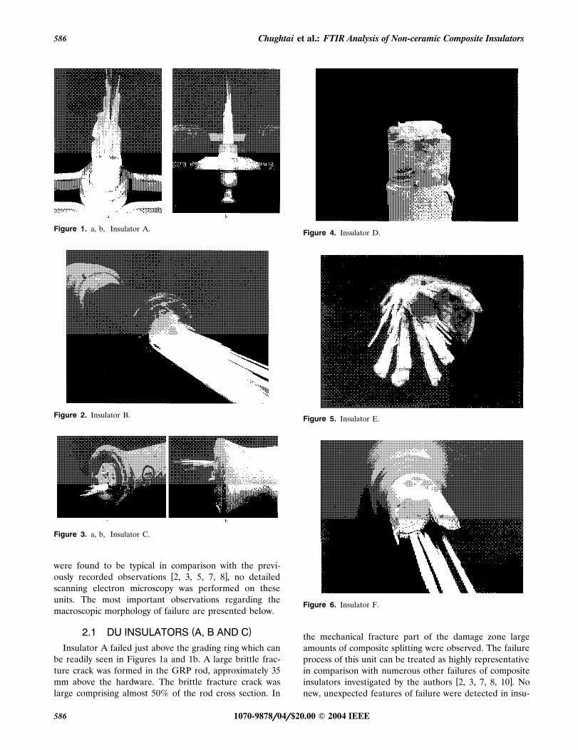
Figure 4. Insulator D.
Figure 5. Insulator E.
Figure 6. Insulator F.
the mechanical fracture part of the damage zone largeamounts of composite splitting were observed. The failureprocess of this unit can be treated as highly representativein comparison with numerous other failures of composite
w xinsulators investigated by the authors 2, 3, 7, 8, 10 . Nonew, unexpected features of failure were detected in insu-
1070-9878rrrrr04rrrrr$20.00 � 2004 IEEE586
IEEE Transactions on Dielectrics and Electrical Insulation Vol. 11, No. 4; August 2004 587
lator A. The failure process of insulator B was very similarŽ .to that of insulator A Figure 2 . Insulator B also failed
above the grading ring, approximately 75 mm from the topsurface of the hardware. The fitting design of this insula-tor was exactly the same as insulator A. Insulators A andB had the epoxy cone fitting design, which was investi-
w x Ž .gated by Kumosa et al. 2�5, 8 . The guide C failed byŽ .brittle fracture just above the hardware Figure 3 . In
comparison with the previous two cases, the brittle frac-Žture crack in guide C was much larger between 80 and
.90% of the rod cross section . There was no rubber hous-ing on the rod surface.
( )2.2 INSULATORS D-FŽ .Only one side of insulator D Figure 4 was used in the
FTIR analysis and therefore the location of failure couldnot be determined with 100% certainty. A large separa-tion was found at the interface between the rod and hous-ing. The main brittle fracture crack was large, occupyingmore than 50% of the rod cross-section. Similar to case
Ž .D, one side of insulator E Figure 5 was used in the FTIRstudy. Therefore, the exact location of failure could notbe precisely established. It appeared however that the de-sign and the manufacturer of this unit were different frominsulators A, B, and D. Contrary to insulators A-D, thebrittle fracture process in insulator E occurred along sev-eral brittle fracture surfaces at different locations alongthe rod, leading to severe rod splitting during the process.Therefore, the exact initiation site of failure could not beclearly identified.
Insulator F is of the same design as insulator E. Theexact location of failure with respect to the hardware couldnot be determined since only one side of the insulator was
Ž .used in the FTIR work Figure 6 . Significantly less split-ting was observed in the case of insulator F, in compari-son with insulator E. One large brittle fracture crack and
Ž .a few secondary ones were found Figure 6 .
The macro-analysis reported above did not provide newobservations which could change our understanding of thebrittle fracture process. Cases A, B, C, D and F could betreated as typical, already thoroughly investigated in pre-
w xvious work by the authors 1 . Only insulator E exhibitedan unusual amount of rod splitting caused by brittle frac-ture.
3 CHEMICAL ANALYSIS OF GRPRODS
Based on the macro-observations it was concluded thatinsulators A-F came from at least two, or three differentmanufacturers. Therefore, it was unclear if the chemicalcompositions of the GRP rods of units A-F were differentor similar. Since the resistance to brittle fracture dependson the chemical composition of the rod material, at least
w xin nitric acid 3, 5, 14�21 , the determination of the rodchemistry for insulators A-F was important. To accom-
plish this, composite samples were collected from insula-tors A-F outside their brittle fracture zones and subjected
Ž .to FTIR tests with a photoacoustic cell at AshlandChemical Company to determine their chemistry. It wasfound that:
� Due to the extremely large background signal at-tributed to the fiberglass, it was hard to clearly identifythe resin type in the samples taken from the rods.
� Based on the FTIR spectra, it was thought that a sim-ilar type of resin was employed in all six rods.
�y1The absorption bands at 800-600 cm revealed the
characteristics of phthalate and the pattern at 1300-1100cmy1 suggested that the resin might be an iso-phthalatetype polyester.
4 FTIR PROCEDURESA Digilab FTS14B, upgraded both in hardware and
software for better performance in data processing, wasw xused to acquire the spectra 29 . Spectra of all samplesŽ .were obtained in KBr matrix Aldrich, FTIR grade . After
thorough mixing, samples were left overnight in an ovenat 110�C. It is possible that a small amount of unreactedmonomer andror volatile degradation product could belost in 110�C heating. However, this would have no bear-ing on the results in this experiment or their interpreta-tion. Before the samples were made into disks, they wereallowed to cool in a desiccator for one hour. The amountof sample in each KBr preparation varied slightly, de-pending upon the material and its IR absorption charac-teristics. In general, however, it was about 0.1 % wrw.
Spectral resolution of 2 cmy1 was maintained through-out this study. In addition, preliminary data were ob-tained showing subtraction of two blank KBr samplesŽ . ŽFigure 7 and a spectrum of HNO in KBr matrix Fig-3
.ure 8 to demonstrate a clean base line and the 1386.8cmy1 nitrate peak, respectively. In all systems, a smallband at 2350 cmy1 is present due to atmospheric CO2
showing a net absorption because of unequal beam paths.ŽSpectra of the two samples of polymer composite ob-
.tained from the base of insulator E exposed to NO rN O2 2 4
and O separately under laboratory conditions were ob-3
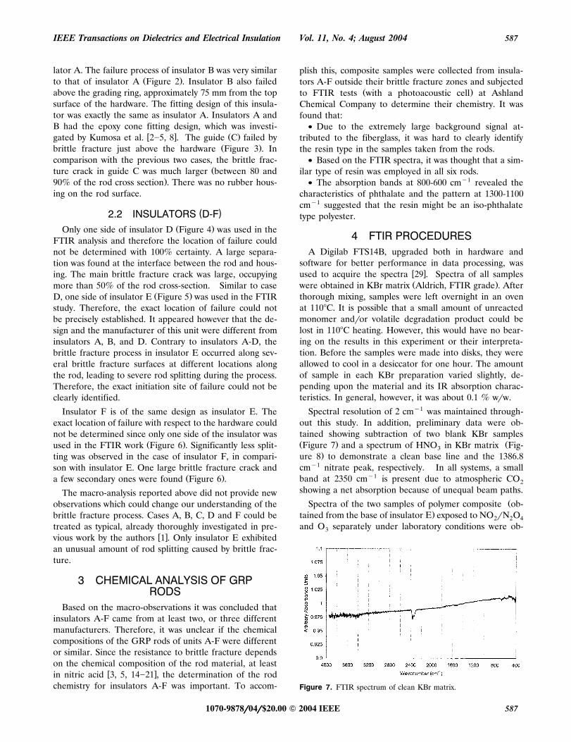
Figure 7. FTIR spectrum of clean KBr matrix.
1070-9878rrrrr04rrrrr$20.00 � 2004 IEEE 587
Chughtai et al.: FTIR Analysis of Non-ceramic Composite Insulators588
Figure 8. FTIR spectrum of HNO in KBr matrix.3
Figure 9. FTIR spectrum of clean material from Insulator E ex-Žposed to NO rN O for 23 h a spectrum of unexposed material is2 2 4
.also shown for comparison .
Figure 10. FTIR spectrum of clean material from Insulator E ex-posed to O for 23 h.3
Ž .tained also Figures 9 and 10 for reference purposes.Wherever necessary, replicate data were obtained. Ex-panded versions of these spectra are also available. Be-tween 5�8 sites were selected for sampling from each ofthe insulators. These sites are illustrated on the pho-tographs shown in Figures 11a, 12a, 13a, 14a, 15a and 16a.The procedures employed in this FTIR study followed
w xthose reported in 1 .
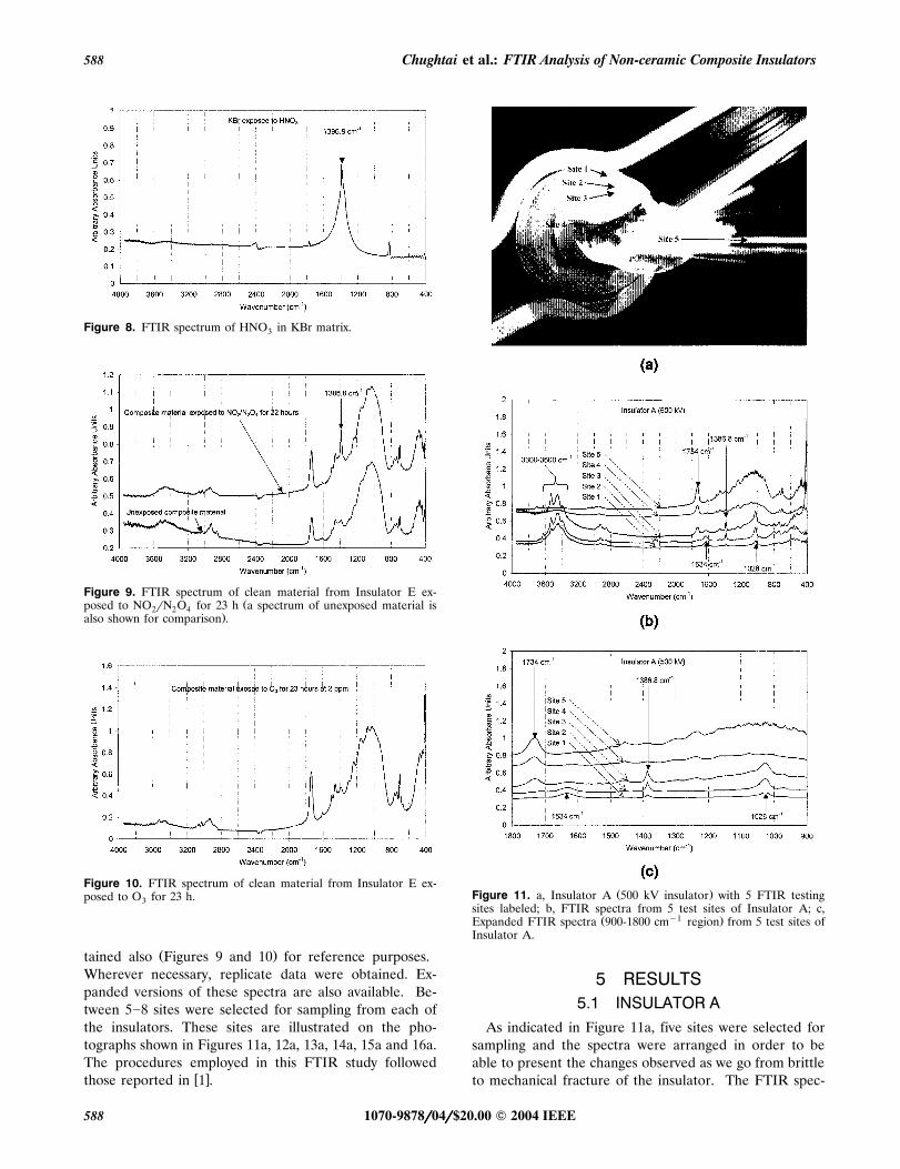
Ž .Figure 11. a, Insulator A 500 kV insulator with 5 FTIR testingsites labeled; b, FTIR spectra from 5 test sites of Insulator A; c,
Ž y1 .Expanded FTIR spectra 900-1800 cm region from 5 test sites ofInsulator A.
5 RESULTS5.1 INSULATOR A
As indicated in Figure 11a, five sites were selected forsampling and the spectra were arranged in order to beable to present the changes observed as we go from brittleto mechanical fracture of the insulator. The FTIR spec-
1070-9878rrrrr04rrrrr$20.00 � 2004 IEEE588

IEEE Transactions on Dielectrics and Electrical Insulation Vol. 11, No. 4; August 2004 589
Ž .Figure 12. a, Insulator B 345 kV insulator with 5 FTIR testingsites labeled; b, FTIR spectra from 5 test sites of Insulator B; c,
Ž y1 .Expanded FTIR spectra 900�1800 cm region from 5 test sites ofInsulator B.
Ž .trum of site 1 Figures 11b and 11c shows nitrate bandsat 1386.8 cmy1, an ethylenic band at 1634 cmy1 and avery small carboxylic band at 1730 cmy1. At sites 2 and 3,the nitrate band at 1386.8 cmy1 is increased substantiallywhile the ethylenic band at 1634 cmy1 diminishes signifi-cantly and the carboxylic band at 1730 cmy1 is increased
Ž .Figure 13. a, Insulator C Guide insulator with 5 FTIR testing siteslabeled; b, FTIR spectra from 5 test sites of Insulator C; c, Expanded
Ž y1 .FTIR spectra 900-1800 cm region from 5 test sites of InsulatorC.
slightly. At locations where mechanical fracture has oc-curred, e.g., sites 4 and 5, the nitrate and ethylenic bandshave diminished, while the carboxylic band at 1730 cmy1
has increased significantly. Absorptions due to OH in the3300�3600 cmy1 region are substantially diminished as thebrittle fracture is passed, while the 1028 cmy1 bandbroadens concurrently.
1070-9878rrrrr04rrrrr$20.00 � 2004 IEEE 589

Chughtai et al.: FTIR Analysis of Non-ceramic Composite Insulators590
Figure 14. a, Insulator D with 8 FTIR testing sites labeled; b, FTIRspectra from 8 test sites of Insulator D; c, Expanded FTIR spectraŽ y1 .900�1800 cm region from 8 test sites of Insulator D.
5.2 INSULATOR BIn this case, as sampling moves inward at sites 1, 2 and
3, there is a gradual increase in the 1386.8 cmy1 bandŽ .Figures 12a�12c . Although there is a decrease in theintensity of the 1386.8 cmy1 band at sites 4 and 5 as com-pared to site 3, the nitrate band still exists. At the same
Figure 15. a, Insulator E with 5 FTIR testing sites labeled; b, FTIRspectra from 5 test sites of Insulator E; c, Expanded FTIR spectraŽ y1 .900-1800 cm region from 5 test sites of Insulator E.
time, the ethylenic band at 1633 cmy1 decreases and thecarboxylic band at 1734 cmy1 shows a gradual increase aswe go from brittle fracture to the mechanical fracture; i.e.,from site 1 to site 5. Also in this case, OH absorption inthe 3300�3600 cmy1 region decreases dramatically, andconcurrently an initially small 1028 cmy1 band broadensand increases.
1070-9878rrrrr04rrrrr$20.00 � 2004 IEEE590

IEEE Transactions on Dielectrics and Electrical Insulation Vol. 11, No. 4; August 2004 591
Figure 16. a, Insulator F with 7 FTIR testing sites labeled; b, FTIRspectra from 7 test sites of Insulator F; c, Expanded FTIR spectraŽ y1 .900-1800 cm region from 7 test sites of Insulator F.
5.3 INSULATOR CFive different sites, similar to those chosen for the above
two insulators, were selected as shown in Figure 13a. Thespectra from this insulator are shown in Figures 13b and13c. This specimen exhibits a different mode of reactionas can be seen that in site 1, four bands are very distinct,i.e., 1327, 1386.8 and 1512 cmy1 and a very broad one at
1653 cmy1. These bands show a gradual decrease, as weprogress from site 1 to site 5. However, the broad band at1653 cmy1 is replaced by another at 1734 cmy1, whichshows a carboxylic group not present in sites 1 and 2, butwhich becomes distinct in sites 3 to 5. The expanded ver-sion of site 4 shows that there is a distinct band at 1641.4cmy1, which decreases significantly in site 5. This sug-gests that in site 1 this band at 1653 cmy1 is a compositeof ethylenic and some other species. The nitrate band at1386.8 cmy1, clearly present at site 1, decreases as theband at 1734 cmy1 increases as we go from site 3 to site 5,accompanied by a strong increase in 500 cmy1, and an-other at 700 cmy1 both of which likely are combinationbands.
5.4 INSULATOR DŽEight sites were selected from this specimen Figure
.14a . This specimen has two charred locations associatedwith the presence of significant delaminations at the GRProdrhousing interface, which appear to have been the re-sult of some highly exothermic chemical reaction or elec-
Žtrical discharge. As is clear from the data Figures 14b.and 14c , the nitrate band increases significantly from sites
1 to 4 and, although remains measurable it decreases fromsites 5 to 8. The broad band at 1643 cmy1 decreases in
Ž .site 2, but in site 3 the edge of the charred location thisband disappears and a carboxylic band appears at 1734
y1 Žcm . However, in site 4 the inner side of the charred.location , this band seems to disappear and a broad enve-
y1 Žlope in 1550�1750 cm is produced similar to site 1 inŽ ..insulator C Guide but then from site 5 to site 8, the
carboxylic band at 1734 cmy1 appears again and progres-sively increases. The nitrate band at 1386.8 cmy1, on theother hand, shows an increase from site 1 to site 3 andthen decreases from site 4 to site 8, although remainingmeasurable.
5.5 INSULATOR EŽ .Five sites were selected from this specimen Figure 15a .
FTIR spectra are shown in Figures 15b and c. It is obvi-ous from the spectra that the nitrate band at 1386.8 cmy1
increases strongly from site 1 to site 3, but diminishes insites 4 and 5 although evidence for nitrate still is clear.The large band in the carboxylic region at 1734 cmy1
shows a small increase from sites 1 to 3.
5.6 INSULATOR FŽ .Seven sites as shown in Figure 16a were selected for
this specimen. FTIR spectra are shown in Figures 16b and16c. The principal features of these spectra are an in-
y1 Ž .crease in the 1734 cm carboxylic band at site 7, mea-surable nitrate at 1386.8 cmy1 which does not changemuch over the 7 sampling sites, and a broadening and in-creased absorption in the region centered around 1100cmy1.
1070-9878rrrrr04rrrrr$20.00 � 2004 IEEE 591

Chughtai et al.: FTIR Analysis of Non-ceramic Composite Insulators592
6 DISCUSSIONInsulators A, B and D were of the same design. The
failure process of this type of design has been studied byw xKumosa et al. 2�5, 8 . The explanation of in-service fail-
w xures of this particular design was presented in 8 . It wasw xstated in 8 that the failures were caused by a combina-
tion of the following factors:
� The end-fittings were not protected against moistureingress.
� Epoxy cones inside the fitting were crushed duringmanufacturing.
� Low quality interface between the GRP rod and rub-ber housing allowing easy transportation of moisture frominside the hardware into the high voltage field above thegrading ring.
E-glassrpolyester composite system was used in the in-sulator GRP rods, which has been shown to have the low-
w xest resistance to stress corrosion cracking 14�21 and thusbrittle fracture.
For insulator A, sample 1 was collected from the rubberhousing in the immediate vicinity of the main brittle frac-ture crack. Sample 2 was collected on the surface of thefractured rubber also very close to the initiation spot of
Ž .the main brittle fracture crack Figure 11a . Sample 3 wascollected from the initiation site of the main brittle frac-ture surface whereas sample 4 was taken from the veryend of the brittle fracture crack, very close to the mechan-
Žical damage zone pure mechanical failure without any.acid influence . For sites 1�3 large peaks were detected in
the FTIR spectra at 1386.8 cmy1 indicating nitrate andthus nitric acid. At the very end of the brittle fracture
Ž .crack site 4 no measurable nitrate band was detected.Another important observation is the fact that a decreasein nitrate activity at 1386.8 cmy1 was associated with an
y1 Ž .increase in absorption at 1734 cm Figure 11c . Thecarboxylic band at 1734 cmy1 increased due to the oxida-tion of the composite surfaces formed during the brittlefracture process due to ozone. It appears that the de-crease in nitric acid concentration is associated with anincrease in this oxidation process.
It can be stated that the failure of insulator A wascaused by the formation of nitric acid inside the insulator,above the grading ring. The largest concentration of nitricacid was found in site 3 indicating that the failure processwas initiated in this location. As the crack propagated to-wards the center of the rod the acid concentration de-creased. At some point of the process, the acid was eithertoo weak or the mechanical stresses too high to generatestress corrosion cracking of the rod material and thus brit-tle fracture. Then, the mechanical failure of the insulatoroccurred.
Insulator B also failed by brittle fracture caused by theŽ .formation of nitric acid Figures 12b and 12c . Large ni-
trate bands at 1386.8 cmy1 were detected especially closeŽ .to the initiation site site 3 in Figure 12a . Also, the sur-
Ž .face of the fractured rubber site 2 was strongly contami-nated by nitric acid. The intensity of the nitrate bandsdecreased as the fracture process propagated across therod. Site 5 in Figure 12a was also found to be slightlycontaminated by nitrate indicating that the part of the rodwhich failed mechanically could have been also contami-nated by nitric acid just before failure, which is certainly
w xpossible 3, 5 . Similar to insulator A the decrease in ni-trate activity at 1386.8 cmy1 was associated with an in-crease in the oxidation process, forming carboxylic bandsat 1734 cmy1.
Insulator D behaved similarly to insulators A and B. Nodetectable nitrate band was found in site 1 indicating that
Žthere was no nitric acid present on the housing. Site 2 on.the rubber very close to the brittle fracture zone exhib-
Ž .ited small traces of nitrate see Figure 14c . The largestconcentration of nitric acid was found on both sides of the
Ž .rodrhousing separation sites 3 and 4 , indicating that themain source of nitric acid production occurred inside therubberrrod separation. As the brittle fracture crack prop-
Ž .agated from its initiation site site 4 towards the center ofŽ . Žthe rod sites 5-8 the acid concentration decreased see
.the nitrate bands in Figure 14c for sites 5-8 . In this casethe intensity of oxidation due to ozone also significantly
Ž .increased as the nitrate activity decreases Figure 14c .
All of the above indicate that insulator D also failed bybrittle fracture caused by nitric acid. The acid was gener-ated at the interface between the GRP rod and the rub-ber housing according to the model proposed by Kumosa
w xet al. 2�8, 10 . Most importantly, the FTIR analysis per-formed here pinpointed for the first time the actual nitricacid generation spot for the type of failure associated withthe formation of main brittle fracture cracks away fromthe hardware.
Based on visual observations it was concluded that insu-lators E and F came from a different manufacturer incomparison with insulators A, B and D. Contrary to theprevious specimens, the brittle fracture process in insula-tor E occurred along several brittle fracture surfaces atdifferent locations along the rod, leading to severe rodsplitting during the process. Therefore, the exact initiationsite of failure could not be clearly identified. Five sampleswere collected from and around the brittle fracture zonesŽ .sites 1-5 in Figure 15a . All sites showed measurable ni-trate bands with the exception of site 1 which was selectedaway from the brittle fracture damage zones. Especially,sites 3 and 4 exhibited nitrate bands of high intensity. Inconclusion, this insulator failed by brittle fracture due tothe formation of nitric acid in-service. The actual locationof acid formation could not be identified due to the se-
Ž .vere damage of the GRP rod multiple splitting . Morecould be said about this particular failure if the other sideof the insulator was available for this analysis.
1070-9878rrrrr04rrrrr$20.00 � 2004 IEEE592

IEEE Transactions on Dielectrics and Electrical Insulation Vol. 11, No. 4; August 2004 593
For insulator F, six samples collected from the brittleŽ .fracture zone sites 2-7 exhibited small, however measur-
able, nitrate bands at 1386.8 cmy1. Sample 1 collected onthe surface of the rubber far away from brittle fracturedid not show any evidence of nitrate. The peak intensities
Žfor sites 2-7 were not as high as in the other cases A, B,.D and E , but were still detectable. For this insulator, sim-
ilar to the several previous cases, a substantial increase inoxidation due to ozone at 1734 cmy1 can be readily seenin Figure 16c. Insulator F failed by brittle fracture causedby nitric acid. Again, more could be said about the actualfailure process if the other side of the unit was available.
The composite guide, labeled as insulator C, did notshow the characteristic failure patterns seen in insulatorsA, B, D, E and F. Only site 1 and site 2 showed any mea-
Ž .surable traces of nitrate Figure 13c . It can be specu-lated, considering the FTIR data presented here, that theguide also failed by brittle fracture caused by nitric acid;however, the acid concentration was much lower than inthe case of the energized insulators. Since the guide wasnot energized in service and it was only subjected to ozoneand water, it is not surprising that the acid concentrationwas found to be very low. The low acid concentration couldalso be caused by the fact that the guide was not pro-tected in service by the rubber housing. Therefore, thecorrosive environment was much more affected by the
Ž .outside atmospheric conditions wind, rain, etc. than inthe case of composite suspension insulators which alwayshave their GRP rods protected by a rubber housing. Even
y1 Ž .though there is some absorption at 1386.8 cm nitrateat site 1, the spectra from guide C have much less nitratethan the other insulators examined. This makes the abso-lute determination of the cause of failure more question-able.
According to a model proposed by Kumosa et al., nitricacid can be formed externally, on the insulator surfaceclose to the energized end fitting, due to water droplet
w xcoronas 30 or internally due to partial discharges insidecracks and large voids present in GRP rods in the pres-
w xence of water 2�8, 10 . The nitric acid formation processcaused by a corona discharge can be described by the fol-
w xlowing reactions 1 :
3O ™2O 1Ž .2 3
N qO ™2NO 2Ž .2 2
2NOqO ™2NO 3Ž .2 2
NOqO ™NO qO . 4Ž .3 2 2
In the presence of moisture
2NO qH O™HNO qHNO 5Ž .2 2 3 2
HNO qO ™HNO qO 6Ž .2 3 3 2
It can be seen from the above reactions that the coronaproduction of O leads to the formation of HNO in the3 3
presence of moisture. The HNO thus formed is respon-3
sible for brittle fracture of the composite. The corona pro-duction of O also leads to the oxidation of any exposed3
composite surfaces.
If relatively strong nitric acid solutions form on the en-ergized end fitting and housing, and if an insulator is notprotected against water ingress, these acidic solutions af-ter penetrating the fitting will reach at some point a GRProd causing stress corrosion and brittle fracture inside the
w xfitting 2, 3, 5, 7, 8, 10 . The critical acid concentration forbrittle fracture under this scenario does not have to bevery high. For E-glassrmodified polyester type GRP rodsthe critical pH of nitric acid was found to be around 3 to
w x3.5 3, 5 , and even slightly higher for a composite basedon straight polyester. These are very important facts sincethe chemical analysis of the rod compositions revealed thatthe most likely resin in the insulators examined in thisstudy is polyester, which has been shown to have the low-est resistance to stress corrosion cracking in nitric acid
w xand thus brittle fracture 14�21 . Such relatively low acidconcentrations can easily be generated under ac discharge
w xover distilled water 27, 31 .
If acid concentration is not high enough, a weak nitricŽacid solution most likely contaminated with all sorts of
.other compounds after penetrating an insulator at the fit-Ž .ting if not protected against moisture ingress in contact
with the GRP rod will not be able to cause SCC and thusŽ .brittle fracture. However, water or weak acids can easily
propagate upwards outside the fitting into the field due tow xcapillary action 2, 3, 7, 8, 10 . This propagation process of
weak acids will be especially easy along the GRPw xrodrhousing interfaces 2, 3, 7, 8, 10 . In addition, water
Ž .always damages the GRP rods without SCC forming alltypes of debondings, delaminations, resin micro-cracking,
w xetc. 28 allowing more water to be absorbed by a compos-ite. Obviously, the effect of either water or weak nitricacid on the GRP composites will very strongly depend on
w xthe composite type 19, 22 .
It has just been shown that the moisture absorption andpropagation in E-glassrmodified polyester composites ismuch faster than in the case of E-glassrepoxy and E-
w xglassrvinyl ester composites 19, 21 . The presence of wa-ter in the E-glassrpolymer pultruded rods will generateinternal cracking along the fiberrmatrix interfaces and thusallow much faster water transport along the rod from in-side the fitting into the high voltage area above the fittingŽ .if grading rings are not present and above the grading
Ž .ring if the rings are present . Then, partial discharges candevelop inside the cracks and voids generated by water,especially if they are occasionally filled with contaminated
w xwater 3, 6, 15 . This has been numerically shown by mod-eling various cracks and large voids inside a GRP rod and
1070-9878rrrrr04rrrrr$20.00 � 2004 IEEE 593
Chughtai et al.: FTIR Analysis of Non-ceramic Composite Insulators594
at the rodrhousing interface near the energized end fit-w xtings 3, 6, 15 .
The presence of internal cracks in the rods occasionallyfilled with water, depending on the moisturerrain condi-tions outside the insulator, and partial discharges will al-low sufficiently strong nitric acid solutions to be formed
Ž .internally inside composite insulators in-service. This willobviously lead to the brittle fracture of a composite insu-
Žlator just outside the fitting or above its grading ring, if.present . The separation at the rodrhousing interface de-
tected in insulator D is the best example of water trans-portation mechanism and internal formation of nitric acidpreviously suggested but not fully proven. The fact thatthe acid concentration was found to be the highest in the
Žvicinity of the separation between sites 3 and 4 in Figure.14c is the best proof of this mechanism. This could be the
most important observation from the entire FTIR analysispresented in this work since, based on the observationsmade by the authors over the years, a vast majority ofinsulator failures have occurred above the hardware.
The water transportation process along the rod fromwithin the energized fitting into the field will be further
w xenhanced by the electric field 24 . It has just been shownin our laboratory that the field moves water upwards along
w xthe rod 24 . The water movement inside an insulator intothe field can be easily traced by tracing metal ions from
Ž . w xthe fitting zinc and iron 3, 5, 7, 8 . These metal ionsfrom the fitting can be always found on the transversebrittle fracture surfaces and axial splits within the brittlefracture zones even at locations quite far away from theenergized end fitting.
The spectral data from all insulator specimens, exceptinsulator C, are consistent with the interpretation thatbrittle fracture is caused by the formation of nitric acidfollowing the reactions presented earlier. The nitrate ab-sorption increases from the exterior surface into the com-posite, while carboxylic group and C-O absorption in-
Ž .creases from O oxidation of the composite surfaces be-3
yond and is highest at the region of mechanical failurebecause of the duration of exposure. This surface oxida-tion is unlikely to contribute materially to insulator fail-ure. The loss of CsC functionality suggests these link-ages as the site of O oxidation of the matrix surface. The3
loss of OH region absorption with depth is consistent withthe role of HNO solution in the brittle fracture process.3
It has been shown by Kumosa et al. that E-glassrpolyes-ter rods in composite insulators which failed by brittle
Žfracture outside the fitting due to the combined effect ofwater, partial discharges in cracks and GRP rodrhousing
.separation always exhibit significant amounts of resin de-w xcomposition 3, 5, 8, 23 . The polymer is very often missing
on the fracture surfaces with large holes present betweenthe glass fibers. The amount of resin decomposition can
w xbe as much as the diameter of the glass fibers 3, 5 . It was
concluded in that work that the resin decomposition wascaused by electrical discharges and ozone oxidation. Ifsuch resin decomposition occurs, the by-product of thedecomposition should be visible in the FTIR data pre-sented in this work for the insulators which failed accord-
Ž .ing to this failure mode insulators A, B, D, E and F . Theamount of by-products caused by the resin decomposi-
Ž .tions should be much smaller if any in the case of thecomposite guide which was not subjected to dischargesin-service. These effects are clearly visible in the FTIRspectra. The carboxylic band at 1734 cmy1 is very inten-
Ž .sive for the five insulator specimens A, B, D, E and Findicating heavy ozone oxidation of the surfaces. Sincethese insulators were energized, high voltage fields existedwhich were responsible for ozone production which in turn
Ž .heavily oxidized the composites. The guide insulator Cwas less affected by such oxidation due to the fact that itis an un-energized structural piece, not directly exposedto high voltage fields. Therefore this piece is only slightlyoxidized by the naturally abundant ozone in the atmo-sphere surrounding it.
It appears that all insulators with the exception of theguide failed outside the fitting following the failure model
w xpreviously proposed 10 and with the formation of nitricacid in-service. The FTIR data and main conclusions pre-sented in this work are in agreement with the previously
w xreported observations in 1 . Most importantly, they shouldprovide further support that nitric acid is the leading causeof brittle fracture failures of composite, non-ceramic insu-lators.
7 CONCLUSIONS
1. The FTIR analyses are consistent with the previousw xobservations of 1 which were based on the FTIR analysis
of an 115 kV suspension composite insulator. Out of sixŽunits subjected to the FTIR analysis, five all energized
.insulators exhibited either significant or at least measur-able amounts of nitrate on their brittle fracture surface.Only the composite guide did not show any significantamounts of nitrate present on its brittle fracture surfaces.
2. Not only was the type of corrosive environment de-termined by FTIR, but also the location of acid genera-tion was pinpointed in some cases. In the case of one in-sulator a large separation at the rodrhousing interface wasfound with the highest acid concentration detected in itsvicinity. It was also shown that the acid concentrationdecreased as the tip of the brittle fracture moved awayfrom the initiation site.
3. Nitric acid generated in service due to corona activi-Ž .ties failures inside the fitting and partial discharges at
Ž .the rodrhousing interfaces failures outside the fitting inthe presence of moisture is the dominant cause of brittlefracture failures of composite suspension insulators.
1070-9878rrrrr04rrrrr$20.00 � 2004 IEEE594

IEEE Transactions on Dielectrics and Electrical Insulation Vol. 11, No. 4; August 2004 595
ACKNOWLEDGEMENTSThis research was funded by the Electric Power Re-
search Institute under contract �EP-P2971rC1399. Theauthors are grateful to Dr. John Stringer of EPRI andMr. R. Stearns of the Bonneville Power AdministrationŽ .Chairman of the Advisory Board of Utilities at DU fortheir support of the insulator research at the University ofDenver.
REFERENCESw x1 A. Chughtai, D. Smith and M. Kumosa, ‘‘Chemical Analysis of a
Field Failed Composite Suspension Insulator’’, Composites Sci.Tech., Vol. 58, pp. 1641�1647, 1998.
w x2 M. Kumosa, ‘‘Failure Analysis of Composite Insulators from theCraig Bonanza Line’’, Final Report to the Western Area PowerAdministration, Oregon Graduate Institute, Portland, Oregon,1994.
w x3 M. Kumosa, Q. Qiu, M. Ziomek-Moroz, A. Moroz and J. M.Braun, ‘‘Micro-Fracture Mechanisms in GlassrPolymer Insula-tor Materials under Combined Effects of Electrical, Mechanicaland Environmental Stresses’’, Final Report to the BonnevillePower Administration, Electric Power Research Institute and theWestern Area Power Administration, Oregon Graduate Insti-
Žtute, Portland, Oregon, 1994 under contract DE-AC79-.92BP61873 .
w x4 M. Kumosa, Q. Qiu, E. Bennett, C. Ek, T. S. McQuarrie and J.M. Braun, ‘‘Brittle Fracture of Non-Ceramic Insulators’’, in theProceed. Fracture Mechanics for Hydroelectric Power SystemsSymposium, Canadian Committee for Research on the Strength
Ž .and Fracture of Materials CSFM , BC Hydro, pp. 235�254,1994.
w x5 Q. Qiu, Brittle Fracture Mechanisms of Glass Fiber ReinforcedPolymer Insulators, Ph.D. Thesis, Oregon Graduate Institute ofScience & Technology, Portland, Oregon, 1995.
w x6 N. Fujimoto, J.M. Braun, M. Kumosa and C. Ek, ‘‘Critical Fieldsin Composite Insulators: Effects of Voids and Contaminations’’,9th Intern. Sympos. HV Eng., Graz, Austria, 1995.
w x7 M. Kumosa and Q. Qiu, ‘‘Failure Analysis of Composite Insula-Žtors Failure Investigation of 500 kV Non-ceramic Insulators for
.Pacific Gas & Electric Company ’’, Final Report to the PacificGas and Electric Company, Department of Engineering, Uni-
Ž .versity of Denver under contact G31-029-95 , 1996.
w x8 M. Kumosa, H. S. Narayan, Q. Qiu and A. Bansal, ‘‘BrittleFracture of Non-Ceramic Suspension Insulators with EpoxyCone End-Fittings’’, Composites Sci. Tech, Vol. 57, pp. 739�751,1997.
w x9 Q. Qiu and M. Kumosa, ‘‘Corrosion of E-Glass Fibers in AcidicEnvironments’’, Composites Sci. Tech., Vol. 57, pp. 497�507,1997.
w x10 ‘‘Interview with M. Kumosa’’, Research of Brittle Fractures inComposite Insulators, Insulator News and Market Report,JulyrAugust, pp. 46�51, 1997.
w x11 D. Armentrout, T. Ely, S. Carpenter and M. Kumosa, ‘‘An In-vestigation of the Brittle Fracture in Composite Materials usedfor High Voltage Insulators’’, J. Acoustic Emission, Vol. 16, No.1-4, pp. S10�S18, 1998.
w x12 S. H. Carpenter and M. Kumosa, ‘‘An Investigation of BrittleFracture of Composite Insulator Rods in an Acidic Environmentwith Static or Cyclic Loading’’, J. Materials Sci., Vol. 35, Issue17, pp. 4465�4476, 2000.
w x13 T. Ely and M. Kumosa, ‘‘The Stress Corrosion Experiments onan E-glassrEpoxy Unidirectional Composite’’, J. Composite Ma-terials, Vol. 34, pp. 841�878, 2000.
w x14 T. Ely, D. Armentrout and M. Kumosa, ‘‘Evaluation of StressCorrosion Properties of Pultruded Glass FiberrPolymer Com-posite Materials’’, J. Composite Materials, Vol. 35, pp. 751�773,2001.
w x15 M. Kumosa, ‘‘Fracture Analysis of Composite Insulators’’, EPRI,Palo Alto, CA, USA, 1006293, 2001.
w x16 M. Megel, L. Kumosa, T. Ely, D. Armentrout and M. Kumosa,‘‘Initiation of Stress Corrosion Cracking in UnidirectionalGlassrPolymer Composite Materials’’, Composites Sci. Tech.,Vol. 61, pp. 231�246, 2001.
w x17 L. Kumosa, D. Armentrout, M. Kumosa, ‘‘An Evaluation of theCritical Conditions for the Initiation of Stress Corrosion Crack-ing in Unidirectional E-glassrPolymer Composites’’, CompositesSci. Tech., 61, pp. 615�623, 2001.
w x18 L. Kumosa, D. Armentrout and M. Kumosa, ‘‘The Effect ofSandblasting on the Initiation of Stress Corrosion Cracking inUnidirectional E-glassrPolymer Composites Used in High Volt-
Ž .age Composite Non-Ceramic Insulators’’, Composites Sci.Tech., Vol. 62, No. 15, pp. 1999�2015, 2002.
w x19 M. Kumosa, ‘‘Failure Analysis of Composite High Voltage Insu-lators’’, EPRI, Palo Alto, CA, USA,1007464, 2002.
w x20 L. Kumosa, M. Kumosa and D. Armentrout, ‘‘Resistance toStress Corrosion Cracking of Unidirectional GlassrPolymerComposites Based on Low and High Seed ECR-glass Fibers forHigh Voltage Composite Insulator Applications’’, Composites,Part A, Vol. 34, No. 1, pp. 1-15, 2003.
w x21 D. Armentrout, M. Kumosa and T. S. McQuarrie, ‘‘Boron FreeFibers for Prevention of Acid Induced Brittle Fracture of Com-posite Insulator GRP Rods’’, IEEE Trans. Power Del., Vol. 18,pp. 684�693, 2003.
w x22 L. Kumosa, B. Benedikt, D. Armentrout and M. Kumosa,‘‘Moistures Absorption Properties of Unidirectional GlassrPoly-mer Composites Used in Non-Ceramic Insulators’’, CompositesPart A, Vol. 35, pp. 1049�1063, 2004.
w x23 M. Kumosa, L. Kumosa and D. Armentrout, ‘‘Can Water CauseŽ .Brittle Fracture Failures of Composite Non-Ceramic Insula-
tors?’’, IEEE Trans. Dielectr. Electr. Insul., in press.w x24 D. Armentrout, M. Kumosa and L. Kumosa, ‘‘The Behavior of
Composite Insulator GRP Rods Subjected to the Water Diffu-sion Electrical Test’’, IEEE Trans. Dielectr. Electr. Insul., sub-mitted for publication.
w x25 J. T. Burnham, T. Baker, A. Bernstorf, C. de Tourreil, J.-M.George, R. Gorur, R. Hartings, B. Hill, A. Jagtiani, T. S. Mc-Quarrie, D. Mitchell, D. Ruff, H. Schneider, D. Shaffner, J. Yuand J. Varner, ‘‘IEEE Task Force Report: Brittle Fracture inNon-Ceramic Insulators’’, IEEE Trans. Power Del., Vol. 17,pp. 848�856, 2002.
w x26 C. de Tourreil, L. Pargamin, G. Thevenet and S. Prat, ‘‘’BrittleFracture’ of Composite Insulators: Why and How They Occur’’,Power Eng. Soc., Summer Meeting, Vol. 4, pp. 2569�2574, 2000.
w x27 M. Kuhl, ‘‘FRP Rods for Brittle Fracture Resistant CompositeInsulators’’, IEEE Trans. Dielectr. Electr. Insul., Vol. 8, pp.182�190, 2001.
w x28 J. Montesinos, R. S. Gorur, B. Mobasher and D. Kingsbury,‘‘Mechanism of Brittle Fracture in Non-Ceramic Insulators’’,IEEE Trans. Dielectr. Electr. Insul., Vol. 9, pp. 236�243, 2002.
w x29 R. T. Lynch, A. R. Chughtai and D. M. Smith, ‘‘Upgrading OlderFTIR Spectrometer Systems’’, American Lab., Vol. 27, pp.20N�20Q, 1995.
w x30 A. J. Phillips, D. J. Childs and H. M. Schneider, ‘‘Aging ofNon-Ceramic Insulators due to Corona from Water Drops’’,IEEE Trans. Power Del., Vol. 14, pp. 1081�1089, 1999.
w x31 A. Goldman, M. Goldman, R.S. Sigmond and T. Sigmond,‘‘Analysis of Corona Products by Means of Their Reactions inWater’’, in Proc. Of the 9th Intern. Sympos. Plasma Chemistry -
ŽVolume 2, edited by R. d’Agostino International Union of Pure.and Applied Chemistry , p. 1654, 1989.
1070-9878rrrrr04rrrrr$20.00 � 2004 IEEE 595

Chughtai et al.: FTIR Analysis of Non-ceramic Composite Insulators596
1070-9878rrrrr04rrrrr$20.00 � 2004 IEEE596