ft i: m> - Bureau of Safety and Environmental Enforcement Reply Refer To: RP-2-1 ft i: m> AEWCO...
15
In Reply Refer To: RP-2-1 ft i: m> AEWCO Production Conpany Attention: Mr. R. A. Fitch Post Office Box 50879 New Orleans, Louisiana 70150 Gentlemen: Reference 1s mace to your Supplemental Plan of exploration received June 28 lCdo, for Lease OCS-G 5*45, Block 401, Mississiopi Canyon Area. This n^'an includes the activities proposed for Wells x and Y. In accordance with JO CFR 250.34, revised December 13, 197°, and our l«Uer dated January 29, 1979, th" plan has ber?r deternined to be complete as of July 12, 1985, and is now . <j<ng considered ^or approval. Your plan control number Is S-1663 and should be rpferenced in your conwunlce tion and correspondence concerning this plan. Sincerely yours. 0. K. Solanas Hr-nional Supervisor Rulos and Production bcc: Lease OCS-G 5845 (OPS-3-2) (FILE ROOM) li J PSr!r 4 w/Publlc I n f o . Copy of die plan (PUBLIC RECORDS ROOM) 00- J ^Gobert:gtj:7/5/35:01sk 3a .. Office ol
-
Upload
nguyenkhanh -
Category
Documents
-
view
213 -
download
0
Transcript of ft i: m> - Bureau of Safety and Environmental Enforcement Reply Refer To: RP-2-1 ft i: m> AEWCO...

In Reply Refer To: RP-2-1 ft i: m>
AEWCO Production Conpany Attention: Mr. R. A. Fitch Post Office Box 50879 New Orleans, Louisiana 70150
Gentlemen:
Reference 1s mace to your Supplemental Plan of exploration received June 28 lCdo, for Lease OCS-G 5*45, Block 401, Mississiopi Canyon Area. This n 'an includes the ac t i v i t i e s proposed for Wells x and Y.
In accordance wi th JO CFR 250.34, revised December 13, 197°, and our l «Uer dated January 29, 1979, th" plan has ber?r deternined to be complete as of July 12, 1985, and is now . <j<ng considered ^or approval.
Your plan control number Is S-1663 and should be rpferenced in your conwunlce tion and correspondence concerning this plan.
Sincerely yours.
0. K. Solanas Hr-nional Supervisor Rulos and Production
bcc: Lease OCS-G 5845 (OPS-3-2) (FILE ROOM) l i J PSr!r 4 w/Publlc Info. Copy of die plan (PUBLIC RECORDS ROOM) 00- J
^Gobert:gt j :7/5/35:01sk 3a
.. Office ol

PUBLIC INFORMATION COPY
Amoco Production Company Amoco Building Post Of lc t Bo* 50879 Ne* Orleans. Louisiana l^.oO
0*'sr>0'e Division
Fi le : RAF-LF
Minerals Management Service Rules and Production P. 0. Box 7944 Metair ie , LA 70010
At ten t ion : Mr. D. W. Solanas Regional Supervise
Supplemental Plan of Fxploration Mississ ippi Canyon Block 401 CCS-G-5845 Offshore Louisiana
In accordance w i t h 30 CFR 250.34-1, Exploration Plan, revised September I i , 1979, and l e t t e r dated January 29, 1979, attached please f i n d nine copies o f Aosco Production Company's Supplemental Plan of Exploration for Mis s i s s ipp i Canyon Block 401, Offshore Louisiana. I t should be noted that Amoco's current approved Plan of Exploration fo r th i s Block also includes Blocks 357, 358 and 402. The attached plan supplements the previous ly f i l e d plan.
Amoco r e s p e c t f u l l y requests your favorable at tent ion to t h i s matter. Should f u r t h e r information be desired, please contact Karty Van of t h i s o f f i c e at telephone 504/586-6567.
Yours s i n c e r e l y ,
KCV
June 26, 1965
A t t a c h m e n t s

SUPPLEMENTAL PLAN OF EXPLORATION
MISSISSIPPI CANYON BLOCK 401
OCS-G-5845
OFFSHORL, LOUISIANA
AMOCO PRODUCTION COMPANY NEW ORLEANS, LOUISIANA
JUNE, 1985

COASTAL ZONE MANAGEMENT
CONSISTENCY CKPTTPTr^TT^
Supplemental P l a n of EXplorgti Typa of Plan
Mississippi Canvon Block 401 Area and Block
OCS-G-5fi4.S
ed a c t i v i t i e s described in cietai _s_ approved Coastal Management i r consistent with such Program.
in this Plan comply with ofiram and w i l l be conducted
Amoco Production Co-Lessee or Operator
R. A. Fitch Certifying O f f i c i a l
JUNJLLJ9S5
PUBLIC INFORMATION CCPY
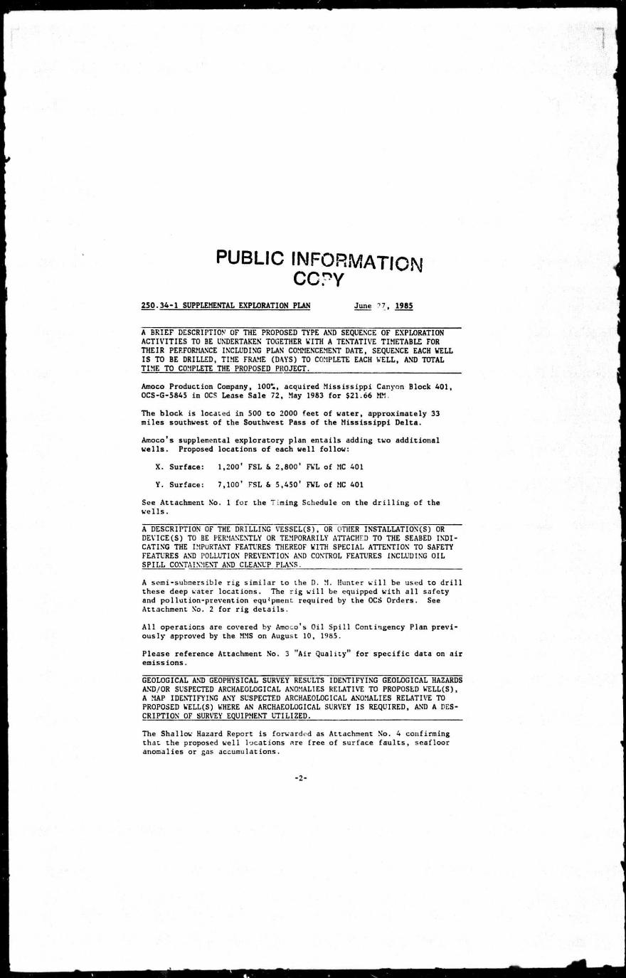
250.34-1 SUPPLEMENTAL EXPLORATION PLAN June ?7, 1985
A BRIEF DESCRIPTION OF THE PROPOSED TYPE AND SEQUENCE OF EXPLORATION ACTIVITIES TO BE UNDERTAKEN TOGETHER VITH A TENTATIVE TIMETABLE FOR THEIR PERFORMANCE INCLUDING PLAN COMMENCEMENT DATE, SEQUENCE EACH VELL IS TO BE DRILLED, TIME FRAME (DAYS) TO COMPLETE EACH VELL, AND TOTAL TIME TO COMPLETE THE PROPOSED PROJECT.
Amoco Production Company, 100*., acquired Mississippi Canyon Block 401, OCS-G-5845 in OCS Lease Sale 72, May 1983 for $21.66 MM.
The block is located in 500 to 2000 feet of water, approximately 33 miles southwest of the Southwest Pass of the Mississippi Delta.
Amoco's supplemental exploratory plan entails adding two additional wells. Proposed locations of each well follow:
X. Surface: 1,200' FSL & 2,800' FVL of MC 401
Y. Surface: 7,100' FSL & 5,450' FVL of MC 401
See Attachment No. 1 for the Timing Schedule on the d r i l l i n g of the wells.
A DESCRIPTION OF THE DRILLING VESSEL(S), OR OTHER INSTALLATION(S) OR DEVICE(S) TO BE PERMANENTLY OR TEMPORARILY ATTACHFD TO THE SEABED INDICATING THE IMPORTANT FEATURES THEREOF VITH SPECIAL ATTENTION TO SAFETY FEATURES AND POLLUTION PREVENTION AND CONTROL FEATURES INCLUDING OIL SPILL CONTAINMENT AND CLEANUP PLANS.
A semi-submersible r i g similar to the D. M. Hunter w i l l be used to d r i l l these deep water locations. The ri g w i l l be equipped with a l l safety and pollution-prevention equ' pmcnt. required by the OCS Orders. See Attachment No. 2 for r i g details.
A l l operations are covered by Amoco's Oil Sp i l l Contingency Plan previously approved by the MMS on August 10, 1985.
Please reference Attachment No. 3 "Air Quality" for specific data on air emissions.
GEOLOGICAL AND GEOPHYSICAL SURVEY RESULTS IDENTIFYING GEOLOGICAL HAZARDS AND/OR SUSPECTED ARCHAEOLOGICAL ANOMALIES RELATIVE TO PROPOSED VELL(S), A MAP IDENTIFYING ANY SUSPECTED ARCHAE0L0CICAL ANOMALIES RELATIVE TO PROPOSED VELL(S) VHERE AN ARCHAEOLOGICAL SURVEY IS REQUIRED, AND A DES-CRIPTION OF SURVEY EQUIPMENT UTILIZED.
The Shallow Hazard Report is forwarded as Attachment No. 4 confirming that the proposed well locations nre free of surface f a u l t s , seafloor anomalies or gas accumulations.
-2-

An archaeological survey was not required. The entire Marine High-Resolu t i o n Geophysical Survey Report in three copies and two volumes is include-' Attachment No. 5.
A LOCATION MAP OF THE LEASE BLOCK(S) RELATIVE TO THE SHORELINE, INCLUDING A DESCRIPTION OF ONSHORE SUPPORT BASE FACILITIES, A LOCATION MAP SHOVING EACH PROPOSED VELL, INCLUDING SURFACE AND PROJECTED BOTTOM-HOLE LOCATION, VATER DEPTH (BATHYMETRY), PROPOSED TRUE VERTICAL AND MEASURED DEPTH OF EACH WELL.
Please reference Attachment No. 6, Location Map This rap shows the relationship of Block 401 Mississippi Canyon area, to the shoreline as well as each of the proposed surface locations of the wells.
Operations w i l l be conducted out of Amoco's base f a c i l i t y at Fourchon, Louisiana. The base is equipped with both a heliport and boat handling f a c i l i t i e s .
CURRENT STRUCTURE MAPS AND, AS APPROPRIATE, SCHEMATIC CROSS SECTIONS SHOVING EXPECTED DEPTH OR MARKER FORMATIONS.
NOTE: Amoco Production Company believes a l l geologic information submitted under this section to be exempt from disclosure under the Freedom of Information Act and i t s implementing regulations.
Attachment Nos. 7 & 8 are Structure Maps demonstrating structural relationships .
Attachment No. 9 is a Schematic Cross Sections showing the geologic sett i n g of the prospects and depicting structural relationships as determined by interpretation of proprietary data.
A BRIEF DESCRIPTION OF PROCEDURES, PERSONNEL, AND EQUIPMENT USED IN YOUR OIL SPILL CONTINGENCY PLAN THAT ARE TO BE USED FOR PREVENTING, REPORTING, AND CLEANING UP A POLLUTION SPILL, INCLUDING EQUIPMENT LOCATION AND TRAVEL AND DEPLOYMENT TIME.
In addition to those systems commonly u t i l i z e d by industry to prevent p o l l u t i o n , Amoco is a member of Clean Gulf Associates which is a combine of companies formed to stockpile equipment for o i l s p i l l cleanup i f such occur. Existing o i l s p i l l cleanup equipment with beach protection and bird-cleaning stations can Le on hand within 18 hours in the event of a s p i l l . This equipment is maintained on standby and in a ready state at locations such as Venice, Louisiana; Grand I s l e , Louisiana; Houma, Louisiana; Intracoastal City, Louisiana; Cameron, Louisiana; Galveston (Texas City), Texas; and Port Aransas (Fulton), Texas.
A l l applicable safety and pollution standards of the MMS, USCG, OSHA, and the EPA w i l l be complied with. A l l personnel w i l l ; trained in the
-3-

proper maintenance of existing equipment and w i l l participate in d r i l l s and inspections designed to enhance their a b i l i t y to u t i l i z e the equipment to i t s f u l l e s t extent and ensure as safe an operation as possible.
A DETAILED LIST OF MUD COMPONENTS AND ADDITIVES, INCLUDING THE COMMON OR CHEMICAL TRADE NAME OF EACH.
Components r f the d r i l l i n g mud may include any or a l l of the following: barite, gel, caustic, soda, chrome lignosuifonate, l i g n i t e , sapp, aluminum stearate, soda ash, phosphate, gilsonite, surfactant (methanol), Quick Seal, Spotty and CMC. No bactericides containing halogenated phenols w i l l be used in the mud system. Any d r i l l i n g mud, d r i l l cuttings, sand, or other solids w i l l not be disposed of into the Gulf unless a l l of the free o i l has been removed.
-4-

1985 1986
SEPT. I OCT. I NOV. I DEC. | JAN. | FEB. | MAR. | APRIL | MAY [ JUNE I JULY | AUG.
75 Days Well X 75 Days I WELL Y
2 3 ATTACHMENT # 1
s Amoco Production Company
£ NEW ORLEANS REGION
Timing Schedule
BLOCK Miss. Canyon 401
h OCS-G-5845

Diamond M Hunter
I f 5 * 23 * 23 a 55" 40 x
Water Depth Capacity 1,500 ft. Dri l l ing Depth Capacity 30.000 ft. Year of Construction 1981
Condition
L-ghtv1-© Occ*i to» F«!d Mo.* r>....-»5
DitplKemcnt Top Deck Load
8.174 5 LT I I 642 LT 11.642 LT 17 012 LT 15 279 a
1.300 ST 2 688 ST 2 frB8 ST 2 688 ST
Classification ABS * A l © AMS
Lenglh 290 ft Beam 200 ft. Hul l* (2)
Beam 35 h Depih 25 ft
Main Deck 95 ft Pipe Rack 113 ft Drill Floor 12825f t Natural Period
Heave 20 7 wc. Roll 40.6 »ec P.tch 31.5 »ec.
Propulsion 5.100 hp.
Capacities Liquid Mud Bulk Material Sack Storage Drill Water Fuel Potable Water Quarters
1.880 bbls 10.000 cu h 5.120 sacks 15 842 bbls. 6.358 bbl* 1.040 bbls 82 man plus 5 man hospital
ATTACHMENT KO. JL

Diamond M Hunter Equipment List
Chains-Eight (8) 2V," x 5 ,200 ' Anchors-Ten (10) 30.000 Ibs. Moorfati Windlasses-Four (4) Skagll double drum
ing single line with 4 0 ' l ine travel and maximum tine load capacity of 16.000 Its. each
Underwater Television-Hydro Products system
Drauworks-Oilwcll E-3000 driven by two (2) GE-752 CC moto** with B^v'or 7836
Dcr-ck- ieO* I>.n^.ic with 1 00'JOOO lb* Sock load
Motion Compensator-Western Gea' -400.000 Ibs capx.rv u t * 20' stroke
Rotary Tatle-OikveU 49VJ " driven by GE-752 DC rr.otor
Crown Block-Pyramid 600 ton Traveling Block-Western Gear 600 ton Hook-BJ-5500 Dynaplex Suivcl-OiWII PC-650 Iron Roughneck-Varco 2000 Kelly Spinncr-Varco 6500 Pipe Spirmcr-Sphner Hawk 13500 Ezy Torque-Drilco model D
Dri l l Pipe-12.500* - 5 " Grade E 19.50 Ib. with 414" IF connections- 7.500' - 5 " Grade S-135 19.50 lb. with 4J4" IF connections; fifteen (15) 5 " heavy wall dnl! n;pe with 4 ! i " IF connections
Dri l l Collars-Nine (9) 9 ' / i " OD x 3 " ID x 3 0 ' long spiral colors witii 7 5
( " API rcgjlar connections; thirty (30) 7 K " OD x 2 , 3 , » " ID x 30 ' long spiral collars with 6 ! t " AP'. regular connections; thirty (30) 6VS" OD X 2 , ,
l t " ID * 30 ' long spiral collars with 4 ' i " IF connections
Kcllys-Two (2) 5 " i " hexagonal raige 3
Divcncr System-Regan m-xiel KFDH with 1 0 " diverter lines
Pin Connector-One (1) 3 0 " Verco Flex Jolnt-Vctco 18V«" with 2 1 " MR-6C conn ction Riser Conncctor-Vctco H-4 1 8 ! « " 10 000 P<>l WP Annular BOP's-Two (2) Shaffer 1S»4 ' 5.000 PSI WP Ram Preventers-Two (2) Cameron double ly-jc " U "
18?*" 10.000 PSI WP Wellhead Connector-Vetco H-4 18 U " 10.000 PSI WP BOP Accumulator Unit-NL Shaffer air-elecrric 660
gal.. 3.000 PSI Emergency BOP Control System-Raytheon two way
acoustic system Kill and Choke Valves-Three (3) 314" C IW 10.000
PSI WP right angle; three (3) 3 f t " CIW 10.000 PSI WP straight thru failsafe gate valves
Marine Riser* 1.500' Vetco 21 " OD >• V i " wall with MR-6C connectors and integral choke and kill line
Riser Pup Joints-Five (5). ten (10). twenty (20). thirty (30) and forty (40) feet long
Slip Joints-Two (2) Vetco 5 5 ' stroke with dual packer and split inserts
Riser Tensioning Units-Four (4) Western Gear dual line v».ith 50 ' line travel and maximum single line load capacity of 80.000 lbs.; total tensioning capacity with eight (8) hnes 640.000 Ibs.
Pod Line Tensioning Units-Two (2) Western Gear single line with 4 0 ' stroke and maximum single line toad capacity of 16.000 Ibs. each
Mud Pumps-Two (2) OiKvell A-1700PT triplex each driven by two (2) GE-752 DC motors
Charging Pumps-Two 12) 5 x 6 centrifugals with 100 HP electric motors
Mud Mixing Pumps-Three (3) 5 x 6 centrifugals with 100 HP electric motors
Srwilcshakcr-Brandt dual tandem high speed Desander Demco 86-V with six (6) 8 " cones Mud Ctcaner-Demco 4-MG16 with sixteen (16) 4 "
cc.-ves Degasscr-Wellco model 5200
AC Generator-Two (2) EMD-16E-9 diesel engines 3070 HP each driving EMD-2100 KW AC generators; one (1) EMD-16E-8 diesel engine 2200 HP driving EMD-1400 KW AC generator
Emergency Generator-One (1) Caterpillar D-3408 di>?sel engine 250 KW AC generator
Power Distribution-Ten (10) Bay SCR system with 750V; two (2) 3.000 amp; four (4) 2,000 amp. four (4) 1.200 amp
Spider Elevators-Three (3) BJ-500 ton slip type with inserts for 7 ". 9*J". and 13ft "
Casing Tongs-Weatherford Lamb model 16.000
Cranes-Two (2) Link Belt API-238A 50 ton cranes with 120' boom; two (2) 60 ton hydraulic bridge cranes for handling BOP stack
One (1) lot portable fire extinguishers per IJ.S.C G.; Halon 1301 flooding system; 150 gallon foam system on heliport; life jackets: four (4) 25 man life rafts; two (2) 50 man lifeboats per U.S.C.G. regulations
Mooring Line Tension-One (1) Bi-M indv.ting system witn eight (8) channel recorder
Vessel Position Reference System-Honeywell RS-904 acoustic type
Dri l l ing Recorder-One (1) Martin Decker seven (7) pen recorder
Pit Level Indicator-Martin Decker Ballast Control System-Electronic control board with
readouts on all tanks
Cementing Unlt-Hallil jrton HT4 with recirculation mixer
Helicopter Pad-Designed to accommodate a Sikorsky S-61N helicopter
Communication System-Single side band; FM; VHF and Marisat units
Distillation Units-Two (2) Koomey reverse osmosis type with 10.000 GPD capacity each
Sewage Treatment System-Red Fox 5500M

ill ! ' v~; 1
Plan of Exploration for Mississippi Canyon Block 401 0CS-G-5845
Air Quality
This attachment includes the infonnation required under 30 CFR Part 250.57(a), to make the net-ssary findings under that section.
Exemption Formula
The distance of the proposed f a c i l i t y from the closest onshore area of a state is 30 statute miles:
The proposed f a c i l i t y is at: latitude 28° 32' 16.29" north, nnd longitude 89° 43' 28.06" west.
The closest onshore area of a state is in Plaquemines parish. Louisiana, at:
latitude 26° 34' 0.0 " north, snd longitude 89° 25' 45.97'' west.
This produces the exemption amount of 999 tons/year for particulates, sulfur dioxide, nitrogen oxides anc. vo l a t i l e organic ccrr.pc jr.ds, and the exemption amount of 32.626 tons/year for carbon monoxide.
Projected Emissions
Dri l l i . i g
The wells proposed to be d r i l l e d on this plan are as follows:
Proposed WoII Proposed Measured Depth (FPOC) Rig Type
::S-G-5645 X CCS-G-5S-0 Y Total Foot Drilled
Semi-Submors ible Seroi-Subrpors ible
23.000
ATTACHMENT HO. A
m

Assuming that the rate of d r i l l i n g w i l l be constant, the t o t a l feet d r i l l e d during each year of the plan are as follows:
1985 20,333 feet 1986 4,667 feet
Assuming 60 horsepower hours required to d r i l l one foot* on an offshore o i l and gas d r i l l i n g r i g , this plan w i l l require 1,219,980 horsepower hours to complete the 1985 portion. The duration of the operations is 122 days. Using the emission factors for diesel powered industrial equipment from Table 3.3.3-1 of EPA publication AP-42, Compilation of Air Pollutant Emission Factors the following t o t a l emissions are expected from this plan:
Carbon Nitrogen Sulfur Monoxide Jxide Hydrocarbons Dioxide Particulates
D r i l l i n g 4.07 18.83 1.51 1.25 1.34 Rig
Ve estimate to have two helicopter landing-takeoff cycles each ' ""v at the d r i l l i n g location for the 122 day period of d r i l l i n g a c t i v i t y . The emission factors per landing-takeoff cycle fo-helicopters from Table 3.2.1-3 of EPA Publication AP-42 proc ;e following helicopter emissions in tons:
Helicopters 0.70 0.07 0.06 0.02 0.03
Ve plan one 2,000 horsepower workboat landing with six hours of i d l i n g three times each week at the d r i l l i n g location. The fuel consumption while i d l i n g at the d r i l l i n g location is seven gallons per hour. The emission factors (7 gallons/hour x 6 hours/landing x 3 landing/week x 18 weeks of d r i l l i n g = 2,266 gallons) for CO, VOC and NOx from diesel vessel emission iactors by operating mode. Table 3.2.3-3, and the factors for SO and particulates from
Table 3.3.3-1 produce the following workboat emissions, in tons, at the d r i l l i n g location:
Workboats 0.33 0.28 0.11 0.04 0.04
Subtotal 5.10 19.18 1.68 1.31 1.41
These emissions are planned to occur in 1985.
Atmospheric emissions from offshore o i l and gas development and production (EPA 450/3-77-026, p. 82-83, June 1977).
-2-

In 1986, we plan to d r i l l 4,667 feet. The emissions from the 1986 drilling operations are as follows:
Emissions in tons/year
Carbon Monoxide
Nitrogen Oxide Hydrocarbons
S u l f u r Dioxide P a r t i c u l
D r i l l i n g 0.94 4.32 0.35 0.29 0.31
Hel icopters 0 16 0.02 0.01 0.01 1.01
Workboats 0.07 0.06 0.02 0.01 0.01
Su. o t a l 1.17 - 40 0.38 0.31 0.33
Th~se emissions are planned t o occur ! n 1986.
The annual emission t o t a l s , i n r j . s , JT * as f o l l o w s :
1985 D r i l l i n g 5.10 19.18 I . . " . * 1.31 1.41
1966 D r i l l i n g 1.17 4.40 0.38 0.31 0.33
Therefore, since none of these a.<-jita approach 999 tons (32.826 tons for carbon monoxide), we request chf.i you determine under Section 250.57(d) that t h i s plan be exempt from further air quality review.
-3

IV tn* Orleans " • f l 'O > ' « o Bu>t<l»ng ~ »t Qtlic* Bo. &0879 f. v 0 > M K I i-omnsn* 70150
Amoco Pre Auct ion Cornpany
June 26, 1985
Minerals Management is--vice Deputy Minerals M-:> %er Offshore Operat ion Support P. 0. Box 7944 Metairie, LA 70010
Gentlemen:
Subject: Shallow Hazard Report Supplement to Pl in of E<plorJtion Miss. Canyon Block 401, OCS-C*J<•J5
A mult i-sensor, high resolut ion, ;eo "s lca l survey was conducted over the entire block. Data sets a t , am m the v i c in i t y o f , eac'** rotation were reviewed in d e t a i l . The results i r J i ca te that these ii»cat*oi." «»:~ free from sui face f a u l t s , seafloor anomalies and shallow gas accummdi .ons. At location "Y" , a very weak, "ocalized anomaly is indicated t'. .".fS3 seconds below the seafloor (approx. 1900 feet ) . Casing programs jno ^•:essar safety uractices j re plann3d to safely penetrate th is zone.
X. 1201' FS. . ?S " FWL Y. 7VOL' "SL, 645' FWL
Serologic control - i r w^ided by four wells recently d r i l l e d by Amoco in Miss. Cu on 3Vcks J57, 359, and 400. A simi lar geologic ser.j^nce is expecte'. at Blc k 401.
Bjrror/lrfGi 11 eon Geophysical Manager La. Offshore Div is ion
BLG/ebc
ATTACHMENT NO. A.

Y- 7100* I SL • 5450 FWL
X-1200'FSL • 2800* FWL
SCALE: r-4000*
VICINITY
ATTACHMENT * 6
Oftshore Louisiana i i
Amou Production Company NEW ORLEANS REGION
3LOCK:Miss. Canyon 401 OCS-5845 LOCATION MAP


![[XLS] · Web view12 cft 11 cft 16 cft 25-90 lb 12.5 ft 16.5 ft 40 gal 90 gal 120 gal 12 gal to 10 ft to 14 ft to 15 ft 61 ft 80 ft 100 ft 37 ft 60 ft 70 ft 125 ft 150 ft 24000 lb](https://static.fdocuments.in/doc/165x107/5af970177f8b9aac248e662f/xls-view12-cft-11-cft-16-cft-25-90-lb-125-ft-165-ft-40-gal-90-gal-120-gal-12.jpg)