INSTRUCTION SHEET Pneumatic Fire &/or Smoke Damper Actuator ...
Installation Instructions FS-1620Issue Date April 9, 2003
© 2003 Johnson Controls, Inc. 1Part No. 44-1121-8, Rev. - www.johnsoncontrols.com
FS-1620 1 1/2 Hour Fire/Class II Smoke Damper
• California State Fire MarshalListing No. 3225-245:005 and 3230-245:109
• New York City BSA No. 176-82-SM
• Underwriters Laboratories®, Inc. (UL)Classified Listing R11172
ApplicationThese combination fire and smoke dampers aredesigned to operate with blades running horizontally.The standard application is with the leading edge ofthe closed blades within the wall or floor; however,they can be manufactured for installation outside thewall or floor.
Maximum UL Classified Sizes – Opposed Blade• Single section vertical and horizontal installation,
36 in. wide x 48 in. high (914 mm x 1219 mm)
• Multiple section assembly vertical and horizontalinstallation, 120 in. wide x 96 in. high (3048 mm x2438 mm)
InstallationRefer to the appropriate installation instructionssupplements for additional information or specialrequirements:
• Drivemate No. 14880 Breakaway Connection
• Flanged System Breakaway Connections
• Mullions for Dampers in Oversized Wall Openings
• Cavity Shaft Wall Metal Stud Framing
• TS150 FireStat for Reopenable Combination Fireand Smoke Dampers
• SP100 Switch Package
• EFL Electric Resettable Fuse Link
• EFL/SP100 Electric Resettable Fuse Link andSwitch Package
• PFL Pneumatic Fuse Link
• DSDN No-Flow Rated Duct Smoke Detector
1. Opening ClearanceThe opening in the wall or floor shall be largerthan the damper/sleeve assembly to permitinstallation or expansion. For two-angleinstallations the opening shall be a minimum of1/8 in. per foot (3 mm per 305 mm) larger thanthe overall size of the damper/sleeve assembly.The maximum opening size shall not exceed1/8 in. per foot (3 mm per 305 mm) plus 2 in.(51 mm), nor shall the opening be less than1/4 in. (6 mm) larger than the damper/sleeveassembly. For one-angle installations, theopening shall be a minimum of 1/4 in. (6 mm) to amaximum of 1 in. (25 mm) larger than the overallsize of the damper/sleeve assembly.
2. Fasteners and Multiple Section AssemblyWhen joining multiple damper assemblies orfastening the damper to the sleeve, dampersshall be fastened with 1/4 in.-20 (M6) bolts, #10(M5) screws, or 1/2 in. (13 mm) long weldsstaggered intermittently on both sides. Space thefasteners 6 in. (152 mm) on center and amaximum 2 in. (51 mm) from the ends of thejoining sections or from each corner. Whenjoining multiple damper assemblies, a continuous1/8 in. (3 mm) bead of Dow Corning® 999-A,Dow Corning Silastic 732® RTV, or GE® RTV108 sealant shall be applied on the mullion joint.Press the surface of the sealant in place to dispelany air. Another bead of the same sealant shallbe applied between the damper and sleeve in thesame manner. Only one side of the damperrequires caulking. Note that the sealant is notrequired when dampers are supplied for firedamper applications only and are not required tobe leakage rated. Multiple section high verticalmount dampers include a 14 gauge x 5 in. (2 mmx 127 mm) wide steel mullion plate sandwichedbetween the damper frames where required. Themullion plate must be the same material as thedampers.
2 FS-1620 Combination Fire/Smoke Damper Installation Instructions
3. Damper SleeveSleeve thickness must be equal to or thicker thanthe duct connected to it. Sleeve gaugerequirements are listed in the Sheet Metal and AirConditioning Contractors' National Association(SMACNA) Fire, Smoke and Radiation DamperInstallation Guide for HVAC Systems and in theNational Fire Protection Association NFPA90A. Ifa breakaway style duct/sleeve connection is notused, the sleeve shall be a minimum of 16 gauge(1.6 mm) for dampers up to 36 in. (914 mm) wideby 24 in. (610 mm) high and 14 gauge (1.9 mm)for dampers exceeding 36 in. (914 mm) wide by24 in. (610 mm) high. Damper sleeve shall notextend more than 6 in. (152 mm) beyond thefirewall or partition unless damper is equippedwith an actuator and/or factory installed accessdoor. Sleeve may extend up to 16 in. (406 mm)beyond the firewall or partition on sides equippedwith actuator and/or factory installed access door.Sleeve shall terminate at both sides of wall withindimensions shown.
4. Damper OrientationDamper is designed to operate with bladesrunning horizontally and must be installed withleading edge of closed blades within the wall orfloor when they are in the closed position. Use"Mount With Arrow Up" label as a guide for properdamper orientation. Horizontal mount dampersmay be installed with actuator above or belowthe floor.
5. Mounting AnglesMounting angles shall be a minimum of 1 1/2 in. x1 1/2 in. x 20 gauge steel (38 mm x 38 mm x1.0 mm). For openings in metal stud, wood studand concrete/masonry walls of sizes 90 in. x49 in. or 49 in. x 90 in. (2286 mm x 1245 mm or1245 mm x 2286 mm) and less, mounting anglesare only required on one side of the wall or topside of the floor and must be attached to both thesleeve and the wall. Mounting angles may beinstalled directly to the metal stud under thewallboard on metal stud wall installations only.Larger openings and floor installations requiremounting angles on both sides of the partition andmust be attached only to the sleeve. Mountingangles must overlap the partition a minimum of1 in. (25 mm). Do not weld or fasten anglestogether at corners of dampers. Angles mustoverlap the partition a minimum of 1 in. (25 mm).Fire/smoke dampers may be installed using FASTangle for one-angle installation or PFMA for two-angle installations.
a. Mounting Angle FastenersMounting angle fasteners shall be #10 (M5)bolts or screws, #10 self-tapping concreteanchors or concrete screws, 1/2 in. (13 mm)long tack welds or 3/16 in. (3 mm) diametersteel rivets.
b. Mounting Angle Fastener SpacingFor one-angle installations the sleevefasteners shall be spaced at 6 in. (152 mm)o.c. and the wall fasteners shall be spaced at12 in. (305 mm) o.c. with a minimum of 2fasteners on each side, top and bottom.Screw fasteners used in metal stud mustengage the metal stud a minimum of 1/2 in.(13 mm). Screw fasteners used in wood studmust engage the wood stud a minimum of3/4 in. (19 mm). Screw fasteners used inmasonry walls or floors must engage the wallor floor a minimum of 1 1/2 in. (38 mm). Fortwo-angle installations the fasteners shall bespaced at 8 in. (203 mm) on centers.
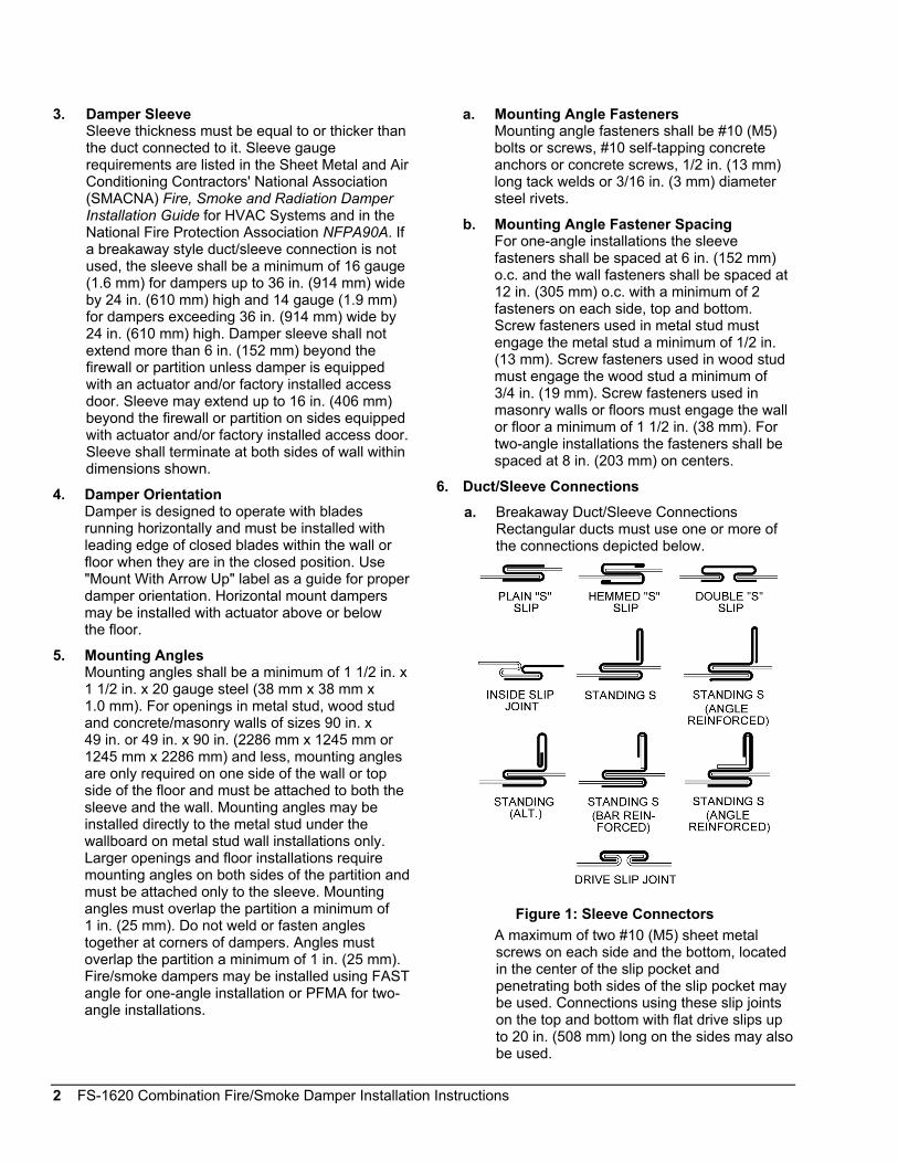
6. Duct/Sleeve Connectionsa. Breakaway Duct/Sleeve Connections
Rectangular ducts must use one or more ofthe connections depicted below.
Figure 1: Sleeve ConnectorsA maximum of two #10 (M5) sheet metalscrews on each side and the bottom, locatedin the center of the slip pocket andpenetrating both sides of the slip pocket maybe used. Connections using these slip jointson the top and bottom with flat drive slips upto 20 in. (508 mm) long on the sides may alsobe used.
FS-1620 Combination Fire/Smoke Damper Installation Instructions 3
b. Round and Oval Breakaway ConnectionsRound and oval breakaway connections mustuse either a 4 in. (102 mm) wide draw bandor #10 (M5) sheet metal screws spacedequally around the circumference of the ductas follows:
• Duct diameters 22 in. (559 mm) andsmaller – maximum three screws.
• Duct diameters over 22 in. (559 mm) andincluding 36 in. (914 mm) – maximumfive screws.
• Duct diameters over 36 in. (914 mm) andup to and including 191 in. (4851 mm)total perimeter – maximum eight screws.
For flat oval ducts, the diameter is consideredthe largest (major) dimension of the duct.These connections are depicted in theSMACNA Fire, Smoke, and Radiation DamperInstallation Guide.
When optional sealing of these joints isdesired, the following sealants may be appliedin accordance with the sealant manufacturer'sinstructions:
• Hardcast, Inc. – Iron-Grip™ 601 sealant
• Precision – PA2084T
• Eco Duct Seal 44-52
c. Flanged Breakaway Style Duct/SleeveConnections.Flanged connection systems manufacturedby Ductmate Industries, Inc., Nexus, Inc. orWard, Inc. are approved breakaway wheninstalled as shown on the Flanged SystemBreakaway Connections Supplement. TDCand TDF roll-formed flanged connectionsusing 3/8 in. (10 mm) steel bolts and nuts,and metal cleats, as tested by SMACNA, areapproved breakaway connections wheninstalled as shown on the Flanged SystemBreakaway Connections Supplement.
d. Non-Breakaway Duct/Sleeve ConnectionsIf other duct/sleeve connections are used, thesleeve shall be a minimum of 16 gauge(1.6 mm) for dampers up to 36 in. (914 mm)wide x 24 in. (610 mm) high and 14 gauge(2.0 mm) for dampers 36 in. (914 mm) wide x24 in. (610 mm) high.
7. Actuator ConnectionsElectric and pneumatic actuators are to beconnected in accordance with wiring and pipingdiagrams developed in compliance withapplicable codes, ordinances, and regulations.
Damper assemblies having more than oneactuator must have all actuators wired to a singleheat-actuated device. This is required forsimultaneous closure of all sections. Refer to theEFL, TS150, EFL/SP100 or PFL OperationInstructions Supplement for wiring and pipingdiagrams.
Note: Install the damper so that it is square and freefrom raking. Compressing or stretching the damperframe into the duct or opening may result in failedoperation.
IMPORTANT: Do not lift the damper using theblades or actuators. Lift or handle the damper usingthe frame or sleeve. Handling or lifting the damperby the blades or actuator may damage the damperand will void the warranty.
IMPORTANT: Examine each smoke damperon a regular basis to ensure it is not rusted orblocked. In addition, test each smoke damperannually or semi-annually, depending on theapplication, and according to the National FireProtection Association (NFPA) standards, to ensureit will perform as intended. Exercise care to ensurethat such tests are performed safely and do notcause system damage.
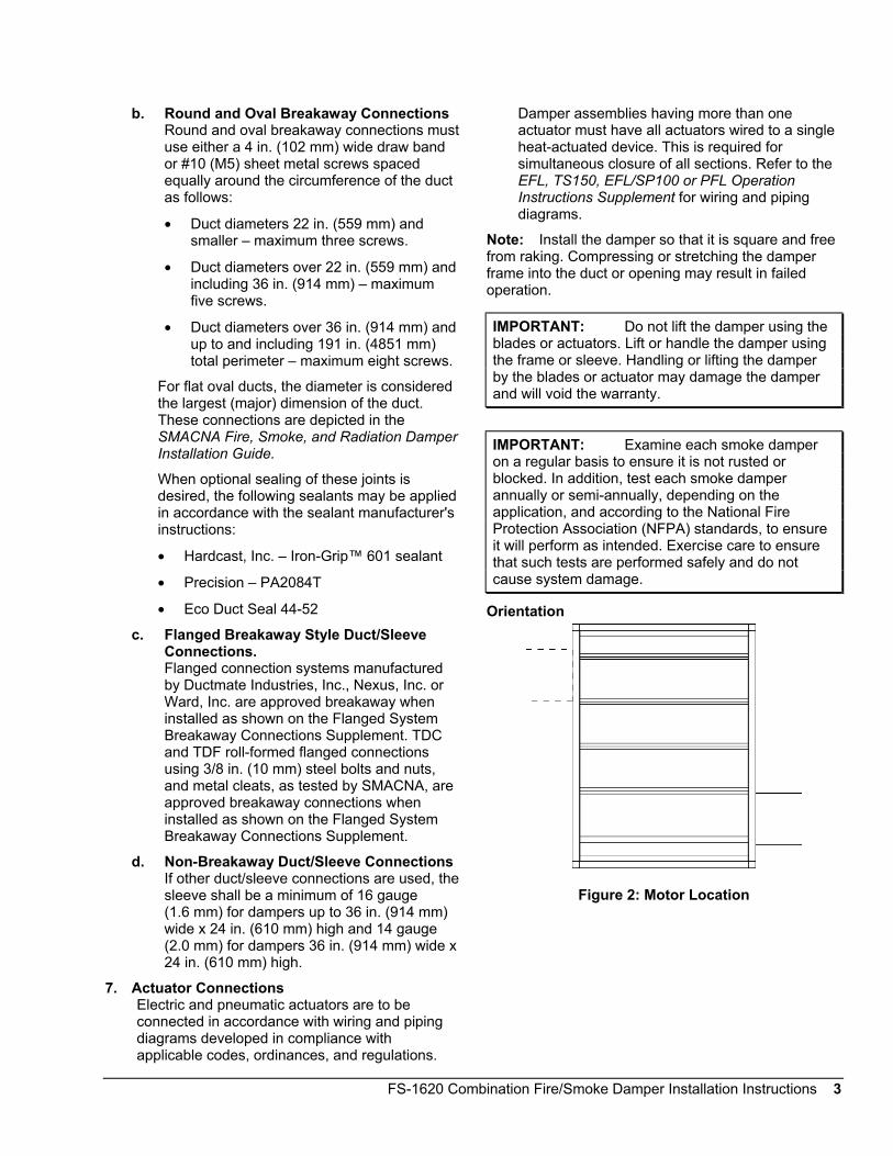
Orientation
Figure 2: Motor Location
4 FS-1620 Combination Fire/Smoke Damper Installation Instructions
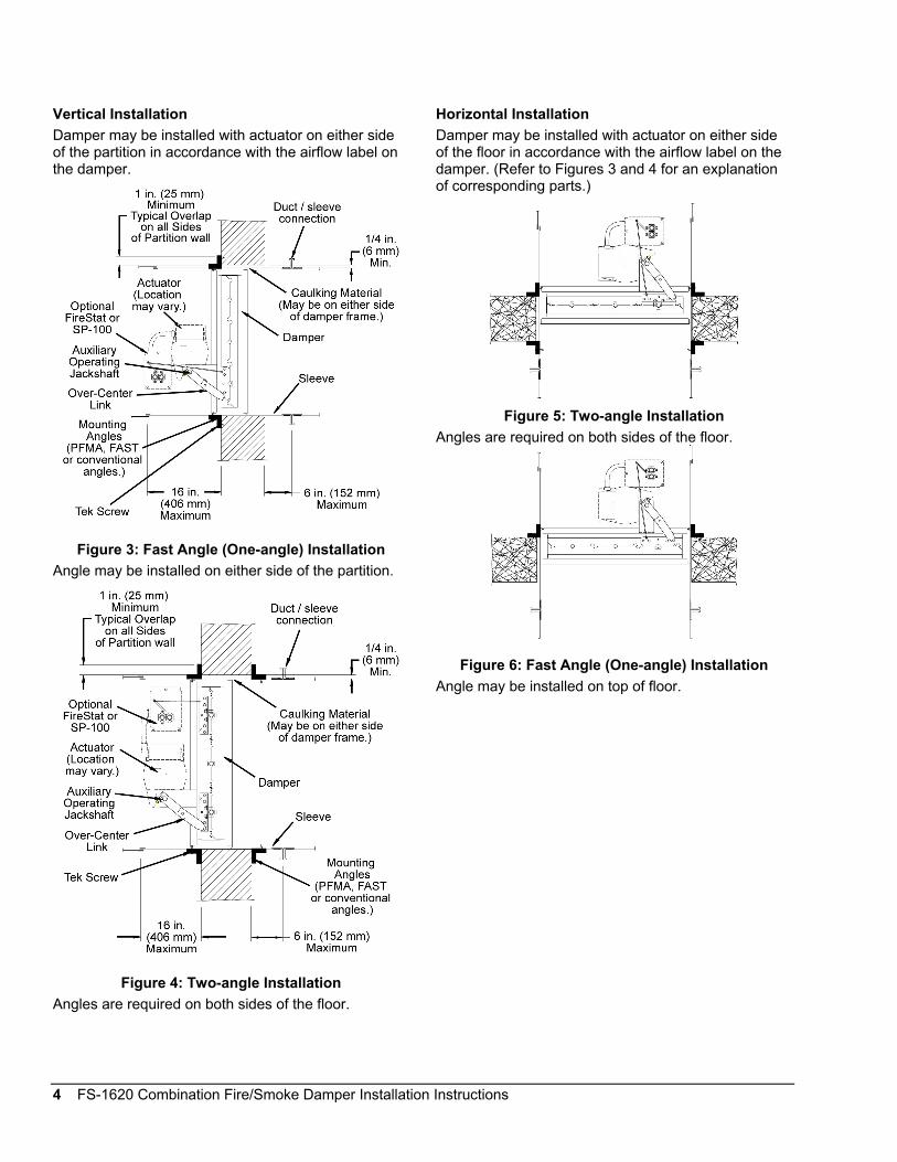
Vertical InstallationDamper may be installed with actuator on either sideof the partition in accordance with the airflow label onthe damper.
Figure 3: Fast Angle (One-angle) InstallationAngle may be installed on either side of the partition.
Figure 4: Two-angle InstallationAngles are required on both sides of the floor.
Horizontal InstallationDamper may be installed with actuator on either sideof the floor in accordance with the airflow label on thedamper. (Refer to Figures 3 and 4 for an explanationof corresponding parts.)
Figure 5: Two-angle InstallationAngles are required on both sides of the floor.
Figure 6: Fast Angle (One-angle) InstallationAngle may be installed on top of floor.
FS-1620 Combination Fire/Smoke Damper Installation Instructions 5
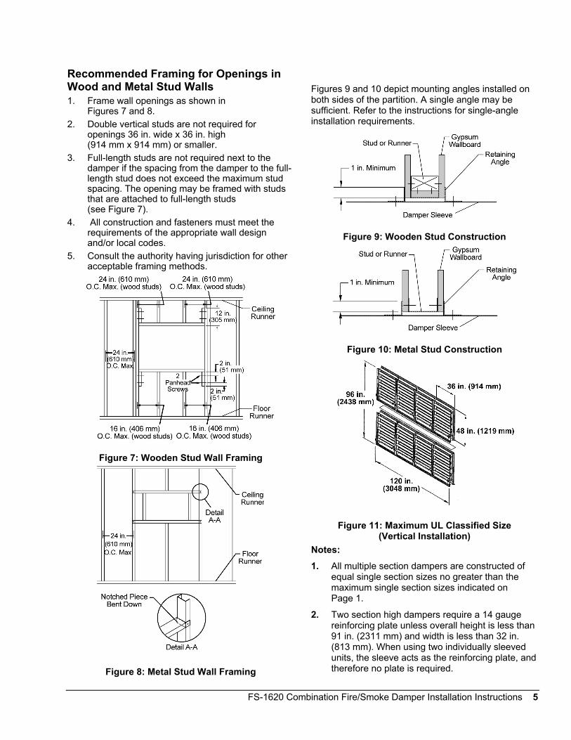
Recommended Framing for Openings inWood and Metal Stud Walls1. Frame wall openings as shown in
Figures 7 and 8.2. Double vertical studs are not required for
openings 36 in. wide x 36 in. high(914 mm x 914 mm) or smaller.
3. Full-length studs are not required next to thedamper if the spacing from the damper to the full-length stud does not exceed the maximum studspacing. The opening may be framed with studsthat are attached to full-length studs(see Figure 7).
4. All construction and fasteners must meet therequirements of the appropriate wall designand/or local codes.
5. Consult the authority having jurisdiction for otheracceptable framing methods.
Figure 7: Wooden Stud Wall Framing
Figure 8: Metal Stud Wall Framing
Figures 9 and 10 depict mounting angles installed onboth sides of the partition. A single angle may besufficient. Refer to the instructions for single-angleinstallation requirements.
Figure 9: Wooden Stud Construction
Figure 10: Metal Stud Construction
Figure 11: Maximum UL Classified Size(Vertical Installation)
Notes:1. All multiple section dampers are constructed of
equal single section sizes no greater than themaximum single section sizes indicated onPage 1.
2. Two section high dampers require a 14 gaugereinforcing plate unless overall height is less than91 in. (2311 mm) and width is less than 32 in.(813 mm). When using two individually sleevedunits, the sleeve acts as the reinforcing plate, andtherefore no plate is required.
6 FS-1620 Combination Fire/Smoke Damper Installation Instructions
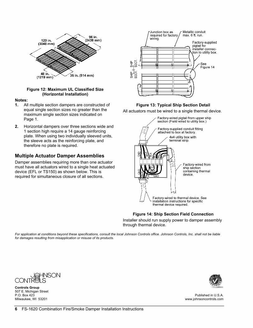
Figure 12: Maximum UL Classified Size(Horizontal Installation)
Notes:1. All multiple section dampers are constructed of
equal single section sizes no greater than themaximum single section sizes indicated onPage 1.
2. Horizontal dampers over three sections wide and1 section high require a 14 gauge reinforcingplate. When using two individually sleeved units,the sleeve acts as the reinforcing plate, andtherefore no plate is required.
Multiple Actuator Damper AssembliesDamper assemblies requiring more than one actuatormust have all actuators wired to a single heat actuateddevice (EFL or TS150) as shown below. This isrequired for simultaneous closure of all sections.
Figure 13: Typical Ship Section DetailAll actuators must be wired to a single thermal device.
Figure 14: Ship Section Field ConnectionInstaller should run supply power to damper assemblythrough thermal device.
For application at conditions beyond these specifications, consult the local Johnson Controls office. Johnson Controls, Inc. shall not be liablefor damages resulting from misapplication or misuse of its products.
Controls Group507 E. Michigan StreetP.O. Box 423 Published in U.S.A.Milwaukee, WI 53201 www.johnsoncontrols.com