FrtBoil - Caltrans - California Department of...
202
** WARNING ** WARNING ** WARNING ** WARNING ** This document is intended for informational purposes only. Users are cautioned that California Department of Transportation (Department) does not assume any liability or responsibility based on these electronic files or for any defective or incomplete copying, exerpting, scanning, faxing or downloading of the contract documents. As always, for the official paper versions of the bidders packages and non-bidder packages, including addenda write to the California Department of Transportation, Plans and Bid Documents, Room 0200, P.O. Box 942874, Sacramento, CA 94272-0001, telephone (916) 654-4490 or fax (916) 654-7028. Office hours are 7:30 a.m. to 4:15 p.m. When ordering bidder or non-bidder packages it is important that you include a telephone number and fax number, P.O. Box and street address so that you can receive addenda.
Transcript of FrtBoil - Caltrans - California Department of...
** WARNING ** WARNING ** WARNING ** WARNING **This document is intended for informational purposes only.
Users are cautioned that California Department of Transportation (Department) does not assume any liability or responsibility based on these electronic files or for any defective or incomplete copying, exerpting, scanning, faxing or downloading of the contract documents. As always, for the official paper versions of the bidders packages and non-bidder packages, including addenda write to the California Department of Transportation, Plans and Bid Documents, Room 0200, P.O. Box 942874, Sacramento, CA 94272-0001, telephone (916) 654-4490 or fax (916) 654-7028. Office hours are 7:30 a.m. to 4:15 p.m. When ordering bidder or non-bidder packages it is important that you include a telephone number and fax number, P.O. Box and street address so that you can receive addenda.
etric
Caltrans
STATE OF CALIFORNIA
DEPARTMENT OF TRANSPORTATION__________________________________________________________
NOTICE TO CONTRACTORSAND
SPECIAL PROVISIONSFOR CONSTRUCTION ON STATE HIGHWAY IN
ORANGE COUNTY IN NEWPORT BEACH NEAR MACARTHUR BOULEVARD OVERCROSSING
DISTRICT 12, ROUTE 73
__________________________________________________________
For Use in Connection with Standard Specifications Dated JULY 1999, Standard Plans Dated JULY 1999, and Labor Surcharge and Equipment Rental Rates.
__________________________________________________________
CONTRACT NO. 12-0C98C4
12-Ora-73-38.0 KP
Bids Open: August 26, 2004Dated: August 2, 2004

TABLE OF CONTENTS
NOTICE TO CONTRACTORS.............................................................................................................................................1COPY OF ENGINEER'S ESTIMATE..................................................................................................................................3SPECIAL PROVISIONS.......................................................................................................................................................6SECTION 1. SPECIFICATIONS AND PLANS..................................................................................................................6AMENDMENTS TO JULY 1999 STANDARD SPECIFICATIONS..................................................................................6SECTION 2. PROPOSAL REQUIREMENTS AND CONDITIONS................................................................................59
2-1.01 GENERAL........................................................................................................................................................592-1.02 DISABLED VETERAN BUSINESS ENTERPRISE (DVBE)........................................................................592-1.03 DVBE GOAL FOR THIS PROJECT...............................................................................................................602-1.04 SUBMISSION OF DVBE INFORMATION...................................................................................................602-1.05 SMALL BUSINESS PREFERENCE...............................................................................................................612-1.06 CALIFORNIA COMPANY PREFERENCE...................................................................................................62
SECTION 3. AWARD AND EXECUTION OF CONTRACT..........................................................................................62SECTION 4. BEGINNING OF WORK, TIME OF COMPLETION AND LIQUIDATED DAMAGES.........................63SECTION 5. GENERAL....................................................................................................................................................63SECTION 5-1. MISCELLANEOUS..................................................................................................................................63
5-1.01 PLANS AND WORKING DRAWINGS.........................................................................................................635-1.011 EXAMINATION OF PLANS, SPECIFICATIONS, CONTRACT, AND SITE OF WORK.......................635-1.012 DIFFERING SITE CONDITIONS.................................................................................................................635-1.013 LINES AND GRADES..................................................................................................................................645-1.015 LABORATORY.............................................................................................................................................645-1.017 CONTRACT BONDS....................................................................................................................................645-1.019 COST REDUCTION INCENTIVE................................................................................................................645-1.02 LABOR NONDISCRIMINATION..................................................................................................................645-1.022 PAYMENT OF WITHHELD FUNDS...........................................................................................................655-1.03 INTEREST ON PAYMENTS..........................................................................................................................655-1.04 PUBLIC SAFETY............................................................................................................................................655-1.05 TESTING..........................................................................................................................................................665-1.06 REMOVAL OF ASBESTOS AND HAZARDOUS SUBSTANCES..............................................................665-1.07 YEAR 2000 COMPLIANCE...........................................................................................................................675-1.08 SUBCONTRACTOR AND DVBE RECORDS..............................................................................................675-1.086 PERFORMANCE OF DVBE SUBCONTRACTORS AND SUPPLIERS...................................................675-1.09 SUBCONTRACTING......................................................................................................................................675-1.10 PROMPT PROGRESS PAYMENT TO SUBCONTRACTORS....................................................................685-1.103 RECORDS......................................................................................................................................................685-1.11 PROTECTED NESTING BIRDS...................................................................................................................685-1.12 AREAS FOR CONTRACTOR'S USE.............................................................................................................685-1.13 PAYMENTS.....................................................................................................................................................695-1.14 SOUND CONTROL REQUIREMENTS.........................................................................................................695-1.15 CULTURAL RESOURCES.............................................................................................................................695-1.16 RELATIONS WITH CALIFORNIA REGIONAL WATER QUALITY CONTROL BOARD.....................705-1.17 ENVIRONMENTALLY SENSITIVE AREA.................................................................................................70
SECTION 6. (BLANK).......................................................................................................................................................70SECTION 7. (BLANK).......................................................................................................................................................70SECTION 8. MATERIALS................................................................................................................................................71SECTION 8-1. MISCELLANEOUS..................................................................................................................................71
8-1.01 SUBSTITUTION OF NON-METRIC MATERIALS AND PRODUCTS......................................................718-1.02 PREQUALIFIED AND TESTED SIGNING AND DELINEATION MATERIALS.....................................778-1.03 SLAG AGGREGATE......................................................................................................................................838-1.04 ENGINEERING FABRICS..............................................................................................................................84
SECTION 8-2. CONCRETE...............................................................................................................................................848-2.01 PORTLAND CEMENT CONCRETE.............................................................................................................84
SECTION 8-3. WELDING.................................................................................................................................................868-3.01 WELDING........................................................................................................................................................86
Contract No. 12-0C98C41

GENERAL.............................................................................................................................................................86WELDING QUALITY CONTROL......................................................................................................................88PAYMENT............................................................................................................................................................90
SECTION 10. CONSTRUCTION DETAILS....................................................................................................................90SECTION 10-1. GENERAL...............................................................................................................................................90
10-1.01 ORDER OF WORK.......................................................................................................................................9010-1.02 WATER POLLUTION CONTROL...............................................................................................................91
RETENTION OF FUNDS.....................................................................................................................................92STORM WATER POLLUTION PREVENTION PLAN PREPARATION, APPROVAL AND AMENDMENTS..........................................................................................................................................92COST BREAK-DOWN.........................................................................................................................................94SWPPP IMPLEMENTATION..............................................................................................................................97MAINTENANCE..................................................................................................................................................98REPORTING REQUIREMENTS.........................................................................................................................98SAMPLING AND ANALYTICAL REQUIREMENTS.......................................................................................99PAYMENT..........................................................................................................................................................100
10-1.03 TEMPORARY FENCE (TYPE ESA)..........................................................................................................101MATERIALS.......................................................................................................................................................101INSTALLATION................................................................................................................................................102MAINTENANCE................................................................................................................................................102MEASUREMENT AND PAYMENT.................................................................................................................102
10-1.04 PRESERVATION OF PROPERTY.............................................................................................................10210-1.05 PROGRESS SCHEDULE............................................................................................................................10210-1.06 OBSTRUCTIONS........................................................................................................................................10210-1.07 DUST CONTROL........................................................................................................................................10310-1.08 MOBILIZATION.........................................................................................................................................10310-1.09 CONSTRUCTION AREA TRAFFIC CONTROL DEVICES....................................................................10310-1.10 CONSTRUCTION AREA SIGNS...............................................................................................................10410-1.11 MAINTAINING TRAFFIC..........................................................................................................................10410-1.12 EXISTING HIGHWAY FACILITIES.........................................................................................................104
SALVAGE COMPOST STORM WATER FILTER TYPE 2 COMPONENTS................................................105ABANDON PIPE LINE.....................................................................................................................................105REMOVE DRAINAGE FACILITY....................................................................................................................105REMOVE CHAIN LINK FENCE.......................................................................................................................106REMOVE CHAIN LINK GATE.........................................................................................................................106EXISTING HIGHWAY IRRIGATION FACILITIES........................................................................................106REMOVE CONCRETE.......................................................................................................................................106
10-1.13 CLEARING AND GRUBBING...................................................................................................................10610-1.14 WATERING.................................................................................................................................................10710-1.15 EARTHWORK.............................................................................................................................................10710-1.16 DUFF............................................................................................................................................................10710-1.17 EROSION CONTROL (BLANKET)...........................................................................................................108
MATERIALS.......................................................................................................................................................108APPLICATION...................................................................................................................................................108MEASUREMENT AND PAYMENT.................................................................................................................108
10-1.18 EROSION CONTROL (TYPE D)................................................................................................................109MATERIALS.......................................................................................................................................................109APPLICATION...................................................................................................................................................110
10-1.19 MAINTAIN EXISTING PLANTED AREAS............................................................................................11110-1.20 FILTER QUANTITIES................................................................................................................................111
MATERIALS.......................................................................................................................................................111APPLICATION...................................................................................................................................................113MAINTENANCE................................................................................................................................................113
10-1.21 ASPHALT CONCRETE..............................................................................................................................11310-1.22 CONCRETE STRUCTURES.......................................................................................................................11610-1.23 REINFORCEMENT.....................................................................................................................................11610-1.24 PLASTIC PIPE.............................................................................................................................................11710-1.25 PLASTIC UNDERDRAIN PIPE.................................................................................................................117
Contract No. 12-0C98C42

10-1.26 REINFORCED CONCRETE PIPE..............................................................................................................11710-1.27 CORRUGATED METAL PIPE...................................................................................................................11710-1.28 CORRUGATED METAL PIPE RISER.......................................................................................................11710-1.29 PERFORATED PLASTIC PIPE UNDERDRAIN.......................................................................................11810-1.30 MISCELLANEOUS FACILITIES...............................................................................................................118
DRAINAGE FACILITY (GROSS SOLIDS REMOVAL DEVICE).................................................................1181200 MM PRECAST CONCRETE PIPE MANHOLE.......................................................................................118
10-1.31 MISCELLANEOUS IRON AND STEEL....................................................................................................11810-1.32 STAINLESS STEEL WIRE MESH.............................................................................................................11810-1.33 GEOMEMBRANE.......................................................................................................................................119
MATERIALS.......................................................................................................................................................119SEAMS................................................................................................................................................................119INSTALLATION................................................................................................................................................120MEASUREMENT...............................................................................................................................................120PAYMENT..........................................................................................................................................................120
10-1.34 GEOTEXTILE..............................................................................................................................................120INSTALLATION................................................................................................................................................120MATERIALS.......................................................................................................................................................120MEASUREMENT...............................................................................................................................................121PAYMENT..........................................................................................................................................................121
10-1.35 COMPOSITE TURF REINFORCEMENT MAT........................................................................................12110-1.36 METERING MANHOLE WITH HS FLUME.............................................................................................12210-1.37 CHAIN LINK FENCE.................................................................................................................................12510-1.38 CHAIN LINK GATE...................................................................................................................................125
STANDARD PLANS LIST
The Standard Plan sheets applicable to this contract include, but are not limited to those indicated below. The Revised Standard Plans (RSP) and New Standard Plans (NSP) which apply to this contract are included as individual sheets of the project plans.
A10A AbbreviationsA10B SymbolsA62D Excavation and Backfill – Concrete Pipe CulvertsRSP A62DA Excavation and Backfill – Concrete Pipe CulvertsA85 Chain Link FenceD75B Pipe InletsD75C Pipe InletsD93C Pipe Riser With Debris Rack CageD102 UnderdrainsT1A Temporary Crash Cushion, Sand Filled (Unidirectional)T1B Temporary Crash Cushion, Sand Filled (Bidirectional)RSP T2 Temporary Crash Cushion, Sand Filled (Shoulder Installations)T3 Temporary Railing (Type K)RS1 Roadside Signs, Typical Installation Details No. 1RS2 Roadside Signs - Wood Post, Typical Installation Details No. 2
Contract No. 12-0C98C43

State Project with DVBE Goals (10-09--03)
DEPARTMENT OF TRANSPORTATION_________________________
NOTICE TO CONTRACTORS
_________________________
CONTRACT NO. 12-0C98C4
12-Ora-73-38.0 KP
Sealed proposals for the work shown on the plans entitled:
STATE OF CALIFORNIA; DEPARTMENT OF TRANSPORTATION; PROJECT PLANS FOR CONSTRUCTION ON STATE HIGHWAY IN ORANGE COUNTY IN NEWPORT BEACH NEAR MACARTHUR BOULEVARD
OVERCROSSING
will be received at the Department of Transportation, 3347 Michelson Drive, Suite 100, Irvine, CA 92612-1692, until 2 o'clock p.m. on August 26, 2004, at which time they will be publicly opened and read in Room C - 1116 at the same address.
Proposal forms for this work are included in a separate book entitled:
STATE OF CALIFORNIA; DEPARTMENT OF TRANSPORTATION; PROPOSAL AND CONTRACT FOR CONSTRUCTION ON STATE HIGHWAY IN ORANGE COUNTY IN NEWPORT BEACH NEAR MACARTHUR
BOULEVARD OVERCROSSING
General work description: Retrofit existing compost storm water filter.
This project has a goal of 3 percent disabled veteran business enterprise (DVBE) participation.No prebid meeting is scheduled for this project.Bids are required for the entire work described herein.At the time this contract is awarded, the Contractor shall possess either a Class A license or a combination of Class C
licenses which constitutes a majority of the work.The Contractor must also be properly licensed at the time the bid is submitted, except that on a joint venture bid a joint
venture license may be obtained by a combination of licenses after bid opening but before award in conformance with Business and Professions Code, Section 7029.1.
This contract is subject to state contract nondiscrimination and compliance requirements pursuant to Government Code, Section 12990.
Preference will be granted to bidders properly certified as a "Small Business" as determined by the Department of General Services, Office of Small Business and Disabled Veteran Business Enterprise Certification (OSDC), at the time of bid opening in conformance with the provisions in Section 2-1.05, "Small Business Preference," of the special provisions, and Section 1896 et seq, Title 2, California Code of Regulations. A form for requesting a "Small Business" preference is included with the bid documents. Applications for status as a "Small Business" must be submitted to the Department of General Services, Office of Small Business and Disabled Veteran Business Enterprise Certification, 707 Third Street, West Sacramento, CA 95605, Telephone Nos. (800) 559-5529 or (916) 375-4940.
A reciprocal preference will be granted to "California company" bidders in conformance with Section 6107 of the Public Contract Code. (See Sections 2 and 3 of the special provisions.) A form for indicating whether bidders are or are not a "California company" is included in the bid documents and is to be filled in and signed by all bidders.
Inquiries or questions based on alleged patent ambiguity of the plans, specifications or estimate must be communicated as a bidder inquiry prior to bid opening. Any such inquiries or questions, submitted after bid opening, will not be treated as a bid protest.
Contract No. 12-0C98C41

Bidder inquiries may be made as follows:
The Department will consider bidder inquiries only when a completed "Bidder Inquiry" form is submitted. A copy of the "Bidder Inquiry" form is available at the Internet address shown below. The bidder inquiry shall include the bidder’s name and telephone number. Submit "Bidder Inquiry" forms to :
Construction Program Duty Senior3337 Michelson Dr., Ste. 380Irvine, CA 92612
Fax Number: (949) 724-2141Tel. Number: (949) 724-2159
To expedite processing, submittal of "Bidder Inquiry" forms via Fax is preferred.To the extent feasible and at the discretion of the Department, completed "Bidder Inquiry" forms submitted for
consideration will be investigated, and responses will be posted on the Internet at:
http://www.dot.ca.gov/hq/esc/oe/project_status/bid_inq.html
The responses to bidders' inquiries, unless incorporated into formal addenda to the contract, are not a part of the contract, and are provided for the bidder’s convenience only. In some instances, the question and answer may represent a summary of the matters discussed rather than a word-for-word recitation. The availability or use of information provided in the responses to bidders' inquiries is not to be construed in any way as a waiver of the provisions of Section 2-1.03 of the Standard Specifications or any other provision of the contract, the plans, Standard Specifications or Special Provisions, nor to excuse the contractor from full compliance with those contract requirements. Bidders are cautioned that subsequent responses or contract addenda may affect or vary a response previously given.
Project plans, special provisions, and proposal forms for bidding this project can only be obtained at the Department of Transportation, Plans and Bid Documents, Room 0200, MS #26, Transportation Building, 1120 N Street, Sacramento, California 95814, FAX No. (916) 654-7028, Telephone No. (916) 654-4490. Use FAX orders to expedite orders for project plans, special provisions and proposal forms. FAX orders must include credit card charge number, card expiration date and authorizing signature. Project plans, special provisions, and proposal forms may be seen at the above Department of Transportation office and at the offices of the District Directors of Transportation at Irvine, Oakland, and the district in which the work is situated. Standard Specifications and Standard Plans are available through the State of California, Department of Transportation, Publications Unit, 1900 Royal Oaks Drive, Sacramento, CA 95815, Telephone No. (916) 445-3520.
Cross sections for this project are not available.The successful bidder shall furnish a payment bond and a performance bond.Pursuant to Section 1773 of the Labor Code, the general prevailing wage rates in the county, or counties, in which the
work is to be done have been determined by the Director of the California Department of Industrial Relations. These wages are set forth in the General Prevailing Wage Rates for this project, available at the Labor Compliance Office at the offices of the District Director of Transportation for the district in which the work is situated, and available from the California Department of Industrial Relations’ Internet Web Site at: http://www.dir.ca.gov. Future effective general prevailing wage rates which have been predetermined and are on file with the Department of Industrial Relations are referenced but not printed in the general prevailing wage rates.
DEPARTMENT OF TRANSPORTATION
Deputy Director Transportation Engineering
Dated August 2, 2004
TLM
Contract No. 12-0C98C42

COPY OF ENGINEER'S ESTIMATE
(NOT TO BE USED FOR BIDDING PURPOSES)
12-0C98C4Item No.
Item Code Item Description Unit of Measure Estimated Quantity
1 071325 TEMPORARY FENCE (TYPE ESA) M 300
2 074019 PREPARE STORM WATER POLLUTION PREVENTION PLAN
LS LUMP SUM
3 074020 WATER POLLUTION CONTROL LS LUMP SUM
4(S)
120090 CONSTRUCTION AREA SIGNS LS LUMP SUM
5(S)
120120 TYPE III BARRICADE EA 3
6 150227 ABANDON PIPELINE EA 1
7 150608 REMOVE CHAIN LINK FENCE M 30
8 033242 REMOVE CHAIN LINK GATE EA 1
9 150668 REMOVE FLARED END SECTION EA 2
10 033243 REMOVE COMPOST STORM WATER FILTER TYPE 2
EA 1
11 150806 REMOVE PIPE M 39
12 150820 REMOVE INLET EA 1
13 033244 REMOVE COMPOST STORM WATER FILTER INLET EA 1
14 033245 SALVAGE COMPOST STORM WATER FILTER TYPE 2 COMPONENTS
EA 1
15 033246 REMOVE CONCRETE (SWALE) M 71
16 160101 CLEARING AND GRUBBING LS LUMP SUM
17 190101 ROADWAY EXCAVATION M3 4280
18 190140 TRENCH EXCAVATION M3 70
19 193120 GRAVEL BACKFILL M3 350
20 200101 IMPORTED TOPSOIL M3 740
Contract No. 12-0C98C43

Item No.
Item Code Item Description Unit of Measure Estimated Quantity
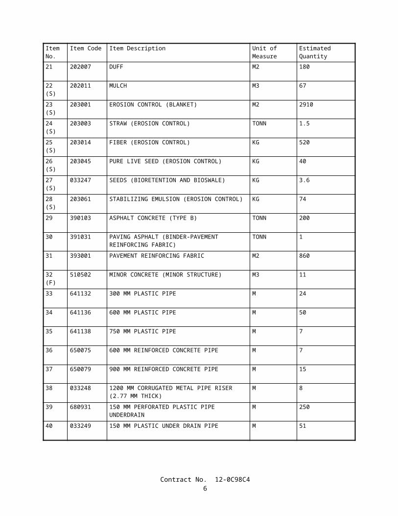
21 202007 DUFF M2 180
22(S)
202011 MULCH M3 67
23(S)
203001 EROSION CONTROL (BLANKET) M2 2910
24(S)
203003 STRAW (EROSION CONTROL) TONN 1.5
25(S)
203014 FIBER (EROSION CONTROL) KG 520
26(S)
203045 PURE LIVE SEED (EROSION CONTROL) KG 40
27(S)
033247 SEEDS (BIORETENTION AND BIOSWALE) KG 3.6
28(S)
203061 STABILIZING EMULSION (EROSION CONTROL) KG 74
29 390103 ASPHALT CONCRETE (TYPE B) TONN 200
30 391031 PAVING ASPHALT (BINDER-PAVEMENT REINFORCING FABRIC)
TONN 1
31 393001 PAVEMENT REINFORCING FABRIC M2 860
32(F)
510502 MINOR CONCRETE (MINOR STRUCTURE) M3 11
33 641132 300 MM PLASTIC PIPE M 24
34 641136 600 MM PLASTIC PIPE M 50
35 641138 750 MM PLASTIC PIPE M 7
36 650075 600 MM REINFORCED CONCRETE PIPE M 7
37 650079 900 MM REINFORCED CONCRETE PIPE M 15
38 033248 1200 MM CORRUGATED METAL PIPE RISER (2.77 MM THICK)
M 8
39 680931 150 MM PERFORATED PLASTIC PIPE UNDERDRAIN
M 250
40 033249 150 MM PLASTIC UNDER DRAIN PIPE M 51
Contract No. 12-0C98C44
Item No.
Item Code Item Description Unit of Measure Estimated Quantity
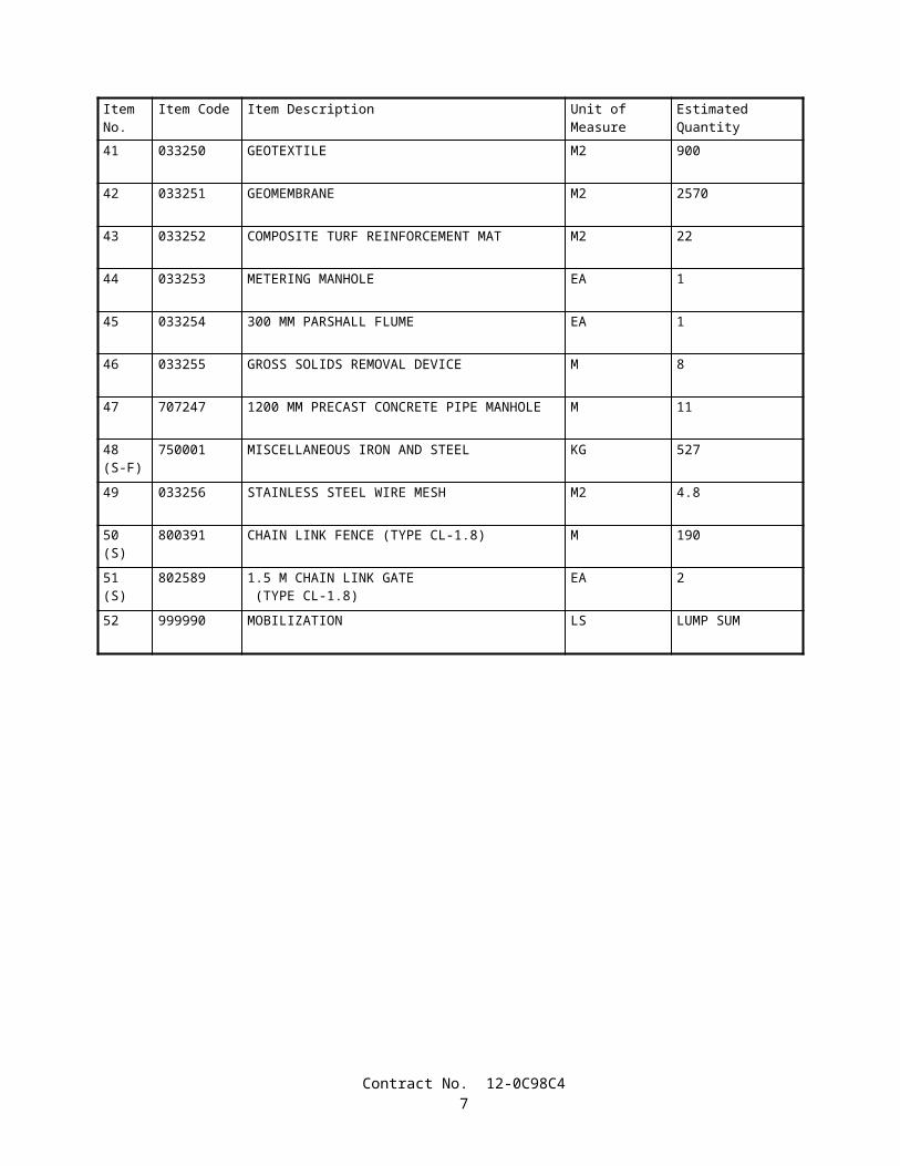
41 033250 GEOTEXTILE M2 900
42 033251 GEOMEMBRANE M2 2570
43 033252 COMPOSITE TURF REINFORCEMENT MAT M2 22
44 033253 METERING MANHOLE EA 1
45 033254 300 MM PARSHALL FLUME EA 1
46 033255 GROSS SOLIDS REMOVAL DEVICE M 8
47 707247 1200 MM PRECAST CONCRETE PIPE MANHOLE M 11
48(S-F)
750001 MISCELLANEOUS IRON AND STEEL KG 527
49 033256 STAINLESS STEEL WIRE MESH M2 4.8
50(S)
800391 CHAIN LINK FENCE (TYPE CL-1.8) M 190
51(S)
802589 1.5 M CHAIN LINK GATE (TYPE CL-1.8)
EA 2
52 999990 MOBILIZATION LS LUMP SUM
Contract No. 12-0C98C45

STATE OF CALIFORNIA
DEPARTMENT OF TRANSPORTATION
_____________________________
SPECIAL PROVISIONS
Annexed to Contract No. 12-0C98C4
SECTION 1. SPECIFICATIONS AND PLANS
The work embraced herein shall conform to the provisions in the Standard Specifications dated July 1999, and the Standard Plans dated July 1999, of the Department of Transportation insofar as the same may apply, and these special provisions.
In case of conflict between the Standard Specifications and these special provisions, the special provisions shall take precedence over and shall be used in lieu of the conflicting portions.
AMENDMENTS TO JULY 1999 STANDARD SPECIFICATIONS
UPDATED March 25, 2004
Amendments to the Standard Specifications set forth in these special provisions shall be considered as part of the Standard Specifications for the purposes set forth in Section 5-1.04, "Coordination and Interpretation of Plans, Standard Specifications and Special Provisions," of the Standard Specifications. Whenever either the term "Standard Specifications is amended" or the term "Standard Specifications are amended" is used in the special provisions, the text or table following the term shall be considered an amendment to the Standard Specifications. In case of conflict between such amendments and the Standard Specifications, the amendments shall take precedence over and be used in lieu of the conflicting portions.
SECTION 2: PROPOSAL REQUIREMENTS AND CONDITIONS
Issue Date: June 19, 2003
Section 2-1.03, "Examination of Plans, Specifications, Contract, and Site of Work," of the Standard Specifications is amended to read:
2-1.03 Examination of Plans, Specifications, Contract, and Site of Work• The bidder shall examine carefully the site of the work contemplated, the plans and specifications, and the proposal
and contract forms therefor. The submission of a bid shall be conclusive evidence that the bidder has investigated and is satisfied as to the general and local conditions to be encountered, as to the character, quality and scope of work to be performed, the quantities of materials to be furnished and as to the requirements of the proposal, plans, specifications and the contract.
• The submission of a bid shall also be conclusive evidence that the bidder is satisfied as to the character, quality and quantity of surface and subsurface materials or obstacles to be encountered insofar as this information was reasonably ascertainable from an inspection of the site and the records of exploratory work done by the Department as shown in the bid documents, as well as from the plans and specifications made a part of the contract.
• Where the Department has made investigations of site conditions including subsurface conditions in areas where work is to be performed under the contract, or in other areas, some of which may constitute possible local material sources, bidders or contractors may, upon written request, inspect the records of the Department as to those investigations subject to and upon the conditions hereinafter set forth.
Contract No. 12-0C98C46

• Where there has been prior construction by the Department or other public agencies within the project limits, records of the prior construction that are currently in the possession of the Department and which have been used by, or are known to, the designers and administrators of the project will be made available for inspection by bidders or contractors, upon written request, subject to the conditions hereinafter set forth. The records may include, but are not limited to, as -built drawings, design calculations, foundation and site studies, project reports and other data assembled in connection with the investigation, design, construction and maintenance of the prior projects.
• Inspection of the records of investigations and project records may be made at the office of the district in which the work is situated, or in the case of records of investigations related to structure work, at the Transportation Laboratory in Sacramento, California.
• When a log of test borings or other record of geotechnical data obtained by the Department's investigation of surface and subsurface conditions is included with the contract plans, it is furnished for the bidders' or Contractor's information and its use shall be subject to the conditions and limitations set forth in this Section 2-1.03.
• In some instances, information considered by the Department to be of possible interest to bidders or contractors has been compiled as "Materials Information." The use of the "Materials Information" shall be subject to the conditions and limitations set forth in this Section 2-1.03 and Section 6-2, "Local Materials."
• When cross sections are not included with the plans, but are available, bidders or contractors may inspect the cross sections and obtain copies for their use, at their expense.
• When cross sections are included with the contract plans, it is expressly understood and agreed that the cross sections do not constitute part of the contract, do not necessarily represent actual site conditions or show location, character, dimensions and details of work to be performed, and are included in the plans only for the convenience of bidders and their use is subject to the conditions and limitations set forth in this Section 2-1.03.
• When contour maps were used in the design of the project, the bidders may inspect those maps, and if available, they may obtain copies for their use.
• The availability or use of information described in this Section 2-1.03 is not to be construed in any way as a waiver of the provisions of the first paragraph in this Section 2-1.03 and bidders and contractors are cautioned to make independent investigations and examinations as they deem necessary to be satisfied as to conditions to be encountered in the performance of the work and, with respect to possible local material sources, the quality and quantity of material available from the property and the type and extent of processing that may be required in order to produce material conforming to the requirements of the specifications.
• The Department assumes no responsibility for conclusions or interpretations made by a bidder or contractor based on the information or data made available by the Department. The Department does not assume responsibility for representation made by its officers or agents before the execution of the contract concerning surface or subsurface conditions, unless that representation is expressly stated in the contract.
• No conclusions or interpretations made by a bidder or contractor from the information and data made available by the Department will relieve a bidder or contractor from properly fulfilling the terms of the contract.
SECTION 5: CONTROL OF WORK
Issue Date: December 31, 2001
Section 5-1.02A, "Trench Excavation Safety Plans," of the Standard Specifications is amended to read:
5-1.02A Excavation Safety Plans• The Construction Safety Orders of the Division of Occupational Safety and Health shall apply to all excavations.
For all excavations 1.5 m or more in depth, the Contractor shall submit to the Engineer a detailed plan showing the design and details of the protective systems to be provided for worker protection from the hazard of caving ground during excavation. The detailed plan shall include any tabulated data and any design calculations used in the preparation of the plan. Excavation shall not begin until the detailed plan has been reviewed and approved by the Engineer.
• Detailed plans of protective systems for which the Construction Safety Orders require design by a registered professional engineer shall be prepared and signed by an engineer who is registered as a Civil Engineer in the State of California, and shall include the soil classification, soil properties, soil design calculations that demonstrate adequate stability of the protective system, and any other design calculations used in the preparation of the plan.
• No plan shall allow the use of a protective system less effective than that required by the Construction Safety Orders.
• If the detailed plan includes designs of protective systems developed only from the allowable configurations and slopes, or Appendices, contained in the Construction Safety Orders, the plan shall be submitted at least 5 days before the Contractor intends to begin excavation. If the detailed plan includes designs of protective systems developed from tabulated
Contract No. 12-0C98C47
data, or designs for which design by a registered professional engineer is required, the plan shall be submitted at least 3 weeks before the Contractor intends to begin excavation.
• Attention is directed to Section 7-1.01E, "Trench Safety."
SECTION 9: MEASUREMENT AND PAYMENT
Issue Date: February 10, 2004
Section 9-1.04, "Notice of Potential Claim," of the Standard Specifications is amended to read:
9-1.04 NOTICE OF POTENTIAL CLAIM• It is the intention of this section that disputes between the parties arising under and by virtue of the contract be
brought to the attention of the Engineer at the earliest possible time in order that the matters may be resolved, if possible, or other appropriate action promptly taken.
• Disputes will not be considered unless the Contractor has first complied with specified notice or protest requirements, including Section 4-1.03, "Changes," Section 5-1.116, "Differing Site Conditions," Section 8-1.06, "Time of Completion," Section 8-1.07, "Liquidated Damages," and Section 8-1.10, "Utility and Non-Highway Facilities."
• For disputes arising under and by virtue of the contract, including an act or failure to act by the Engineer, the Contractor shall provide a signed written initial notice of potential claim to the Engineer within 5 days from the date the dispute first arose. The initial notice of potential claim shall provide the nature and circumstances involved in the dispute which shall remain consistent through the dispute. The initial notice of potential claim shall be submitted on Form CEM-6201A furnished by the Department and shall be certified with reference to the California False Claims Act, Government Code Sections 12650-12655. The Contractor shall assign an exclusive identification number for each dispute, determined by chronological sequencing, based on the date of the dispute.
• The exclusive identification number for each dispute shall be used on the following corresponding documents:
A. Initial notice of potential claim.B. Supplemental notice of potential claim.C. Full and final documentation of potential claim.D. Corresponding claim included in the Contractor's written statement of claims.
• The Contractor shall provide the Engineer the opportunity to examine the site of work within 5 days from the date of the initial notice of potential claim. The Contractor shall proceed with the performance of contract work unless otherwise specified or directed by the Engineer.
• Throughout the disputed work, the Contractor shall maintain records that provide a clear distinction between the incurred direct costs of disputed work and that of undisputed work. The Contractor shall allow the Engineer access to the Contractor's project records deemed necessary by the Engineer to evaluate the potential claim within 20 days of the date of the Engineer's written request.
• Within 15 days of submitting the initial notice of potential claim, the Contractor shall provide a signed supplemental notice of potential claim to the Engineer that provides the following information:
A. The complete nature and circumstances of the dispute which caused the potential claim.B. The contract provisions that provide the basis of claim.C. The estimated cost of the potential claim, including an itemized breakdown of individual costs and how the estimate
was determined.D. A time impact analysis of the project schedule that illustrates the effect on the scheduled completion date due to
schedule changes or disruptions where a request for adjustment of contract time is made.
• The information provided in items A and B above shall provide the Contractor's complete reasoning for additional compensation or adjustments.
• The supplemental notice of potential claim shall be submitted on Form CEM-6201B furnished by the Department and shall be certified with reference to the California False Claims Act, Government Code Sections 12650-12655. The Engineer will evaluate the information presented in the supplemental notice of potential claim and provide a written response to the Contractor within 20 days of its receipt. If the estimated cost or effect on the scheduled completion date changes, the Contractor shall update information in items C and D above as soon as the change is recognized and submit this information to the Engineer.
• Within 30 days of the completion of work related to the potential claim, the Contractor shall provide the full and final documentation of potential claim to the Engineer that provides the following information:
Contract No. 12-0C98C48
A. A detailed factual narration of events fully describing the nature and circumstances that caused the dispute, including, but not limited to, necessary dates, locations, and items of work affected by the dispute.
B. The specific provisions of the contract that support the potential claim and a statement of the reasons these provisions support and provide a basis for entitlement of the potential claim.
C. When additional monetary compensation is requested, the exact amount requested calculated in conformance with Section 9-1.03, "Force Account Payment," or Section 8-1.09, "Right of Way Delays," including an itemized breakdown of individual costs. These costs shall be segregated into the following cost categories:
1. Labor – A listing of individuals, classifications, regular hours and overtime hours worked, dates worked, and other pertinent information related to the requested reimbursement of labor costs.
2. Materials – Invoices, purchase orders, location of materials either stored or incorporated into the work, dates materials were transported to the project or incorporated into the work, and other pertinent information related to the requested reimbursement of material costs.
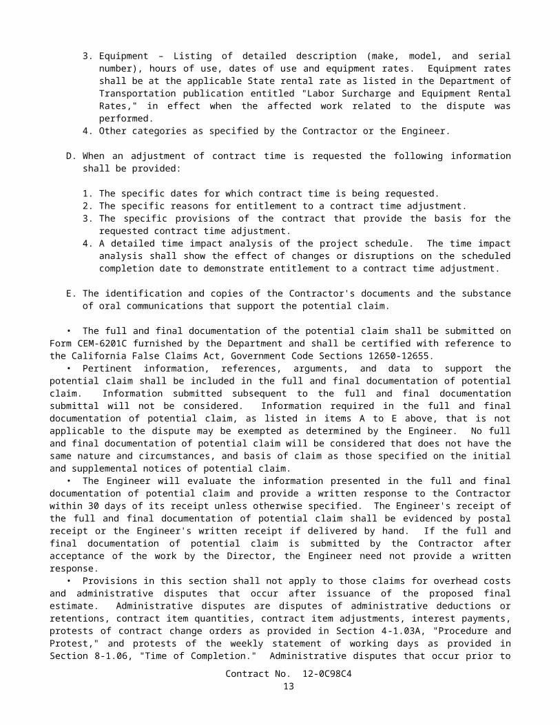
3. Equipment – Listing of detailed description (make, model, and serial number), hours of use, dates of use and equipment rates. Equipment rates shall be at the applicable State rental rate as listed in the Department of Transportation publication entitled "Labor Surcharge and Equipment Rental Rates," in effect when the affected work related to the dispute was performed.
4. Other categories as specified by the Contractor or the Engineer.
D. When an adjustment of contract time is requested the following information shall be provided:
1. The specific dates for which contract time is being requested.2. The specific reasons for entitlement to a contract time adjustment.3. The specific provisions of the contract that provide the basis for the requested contract time adjustment.4. A detailed time impact analysis of the project schedule. The time impact analysis shall show the effect of
changes or disruptions on the scheduled completion date to demonstrate entitlement to a contract time adjustment.
E. The identification and copies of the Contractor's documents and the substance of oral communications that support the potential claim.
• The full and final documentation of the potential claim shall be submitted on Form CEM-6201C furnished by the Department and shall be certified with reference to the California False Claims Act, Government Code Sections 12650-12655.
• Pertinent information, references, arguments, and data to support the potential claim shall be included in the full and final documentation of potential claim. Information submitted subsequent to the full and final documentation submittal will not be considered. Information required in the full and final documentation of potential claim, as listed in items A to E above, that is not applicable to the dispute may be exempted as determined by the Engineer. No full and final documentation of potential claim will be considered that does not have the same nature and circumstances, and basis of claim as those specified on the initial and supplemental notices of potential claim.
• The Engineer will evaluate the information presented in the full and final documentation of potential claim and provide a written response to the Contractor within 30 days of its receipt unless otherwise specified. The Engineer's receipt of the full and final documentation of potential claim shall be evidenced by postal receipt or the Engineer's written receipt if delivered by hand. If the full and final documentation of potential claim is submitted by the Contractor after acceptance of the work by the Director, the Engineer need not provide a written response.
• Provisions in this section shall not apply to those claims for overhead costs and administrative disputes that occur after issuance of the proposed final estimate. Administrative disputes are disputes of administrative deductions or retentions, contract item quantities, contract item adjustments, interest payments, protests of contract change orders as provided in Section 4-1.03A, "Procedure and Protest," and protests of the weekly statement of working days as provided in Section 8-1.06, "Time of Completion." Administrative disputes that occur prior to issuance of the proposed final estimate shall follow applicable requirements of this section. Information listed in the supplemental notice and full and final documentation of potential claim that is not applicable to the administrative dispute may be exempted as determined by the Engineer.
• Unless otherwise specified in the special provisions, the Contractor may pursue the administrative claim process pursuant to Section 9-1.07B, "Final Payment and Claims," for any potential claim found by the Engineer to be without merit.
• Failure of the Contractor to conform to specified dispute procedures shall constitute a failure to pursue diligently and exhaust the administrative procedures in the contract, and is deemed as the Contractor's waiver of the potential claim and a waiver of the right to a corresponding claim for the disputed work in the administrative claim process in conformance with
Contract No. 12-0C98C49

Section 9-1.07B, "Final Payment of Claims," and shall operate as a bar to arbitration pursuant to Section 10240.2 of the California Public Contract Code.
Contract No. 12-0C98C410

Section 9-1.07B, "Final Payment and Claims," of the Standard Specifications is amended to read:
9-1.07B Final Payment and Claims• After acceptance by the Director, the Engineer will make a proposed final estimate in writing of the total amount
payable to the Contractor, including an itemization of the total amount, segregated by contract item quantities, extra work and other bases for payment, and shall also show each deduction made or to be made for prior payments and amounts to be kept or retained under the provisions of the contract. Prior estimates and payments shall be subject to correction in the proposed final estimate. The Contractor shall submit written approval of the proposed final estimate or a written statement of claims arising under or by virtue of the contract so that the Engineer receives the written approval or statement of claims no later than close of business of the thirtieth day after receiving the proposed final estimate. If the thirtieth day falls on a Saturday, Sunday or legal holiday, then receipt of the written approval or statement of claims by the Engineer shall not be later than close of business of the next business day. The Contractor's receipt of the proposed final estimate shall be evidenced by postal receipt. The Engineer's receipt of the Contractor's written approval or statement of claims shall be evidenced by postal receipt or the Engineer's written receipt if delivered by hand.
• On the Contractor's approval, or if the Contractor files no claim within the specified period of 30 days, the Engineer will issue a final estimate in writing in conformance with the proposed final estimate submitted to the Contractor, and within 30 days thereafter the State will pay the entire sum so found to be due. That final estimate and payment thereon shall be conclusive and binding against both parties to the contract on all questions relating to the amount of work done and the compensation payable therefor, except as otherwise provided in Sections 9-1.03C, "Records," and 9-1.09, "Clerical Errors."
• If the Contractor within the specified period of 30 days files claims, the Engineer will issue a semifinal estimate in conformance with the proposed final estimate submitted to the Contractor and within 30 days thereafter the State will pay the sum found to be due. The semifinal estimate and corresponding payment shall be conclusive and binding against both parties to the contract on each question relating to the amount of work done and the compensation payable therefor, except insofar as affected by the claims filed within the time and in the manner required hereunder and except as otherwise provided in Sections 9-1.03C, "Records," and 9-1.09, "Clerical Errors."
• Except for claims for overhead costs and administrative disputes that occur after issuance of the proposed final estimate, the Contractor shall only provide the following two items of information for each claim:
A. The exclusive identification number that corresponds to the supporting full and final documentation of potential claim.
B. The final amount of requested additional compensation.
• If the final amount of requested additional compensation is different than the amount of requested compensation included in the full and final documentation of potential claim, the Contractor shall provide in the written statement of claims the reasons for the changed amount, the specific provisions of the contract which support the changed amount, and a statement of the reasons the provisions support and provide a basis for the changed amount. If the Contractor's claim fails to provide an exclusive identification number or if there is a disparity in the provided exclusive identification number, the Engineer will notify the Contractor of the omission or disparity. The Contractor shall have 15 days after receiving notification from the Engineer to correct the omission or disparity. If after the 15 days has elapsed, there is still an omission or disparity of the exclusive identification number assigned to the claim, the Engineer will assign the number. No claim will be considered that has any of the following deficiencies:
A. The claim does not have the same nature, circumstances, and basis as the corresponding full and final documentation of potential claim.
B. The claim does not have a corresponding full and final documentation of potential claim.C. The claim was not included in the written statement of claims.D. The Contractor did not comply with applicable notice or protest requirements of Sections 4-1.03, "Changes,"
5-1.116, "Differing Site Condition," 8-1.06, "Time of Completion," 8-1.07, "Liquidated Damages," 8-1.10, "Utility and Non-Highway Facilities," and 9-1.04, "Notice of Potential Claim."
• Administrative disputes that occur after issuance of the proposed final estimate shall be included in the Contractor's written statement of claims in sufficient detail to enable the Engineer to ascertain the basis and amounts of those claims.
• The Contractor shall keep full and complete records of the costs and additional time incurred for work for which a claim for additional compensation is made. The Engineer or designated claim investigators or auditors shall have access to those records and any other records as may be required by the Engineer to determine the facts or contentions involved in the claims. Failure to permit access to those records shall be sufficient cause for denying the claims.
Contract No. 12-0C98C411

• The written statement of claims submitted by the Contractor shall be accompanied by a notarized certificate containing the following language:
Under the penalty of law for perjury or falsification and with specific reference to the California False Claims Act, Government Code Section 12650 et. seq., the undersigned,
.(name)
of(title)
.(company)
hereby certifies that the claim for the additional compensation and time, if any, made herein for the work on this contract is a true statement of the actual costs incurred and time sought, and is fully documented and supported under the contract between parties.
Dated
/s/
Subscribed and sworn before me this day
of .
(Notary Public)My Commission Expires
• Failure to submit the notarized certificate will be sufficient cause for denying the claim.• Claims for overhead type expenses or costs, in addition to being certified as stated above, shall be supported and
accompanied by an audit report of an independent Certified Public Accountant. Omission of a supporting audit report of an independent Certified Public Accountant shall result in denial of the claim and shall operate as a bar to arbitration, as to the claim, in conformance with the requirements in Section 10240.2 of the California Public Contract Code. Claims for overhead type expenses or costs shall be subject to audit by the State at its discretion. The costs of performing an audit examination and submitting the report shall be borne by the Contractor. The Certified Public Accountant's audit examination shall be performed in conformance with the requirements of the American Institute of Certified Public Accountants Attestation Standards. The audit examination and report shall depict the Contractor's project and company-wide financial records and shall specify the actual overall average daily rates for both field and home office overhead for the entire duration of the project, and whether the costs have been properly allocated. The rates of field and home office overhead shall exclude unallowable costs as determined in Title 48 of the Federal Acquisition Regulations, Chapter 1, Part 31. The audit examination and report shall determine if the rates of field and home office overhead are:
A. Allowable in conformance with the requirements in Title 48 of the Federal Acquisition Regulations, Chapter 1, Part 31.
B. Adequately supported by reliable documentation.C. Related solely to the project under examination.
• Costs or expenses incurred by the State in reviewing or auditing claims that are not supported by the Contractor's cost accounting or other records shall be deemed to be damages incurred by the State within the meaning of the California False Claims Act.
• If the Contractor files a timely written statement of claims in response to the proposed final estimate, the District that administers the contract will submit a claim position letter to the Contractor by hand delivery or deposit in the U.S. mail within 135 days of acceptance of the contract. The claim position letter will delineate the District's position on the Contractor's claims. If the Contractor disagrees with the claim position letter, the Contractor shall submit a written notification of its disagreement and a written request to meet with the board of review, to be received by the District not later than 15 days after the Contractor's receipt of the claim position letter. The written notification of disagreement shall set forth the basis for the Contractor's disagreement and be submitted to the office designated in the claim position letter. The
Contract No. 12-0C98C412

Contractor's failure to provide a timely written notification of disagreement or timely written request to meet with the board of review shall constitute the Contractor's acceptance and agreement with the determinations provided in the claim position letter and with final payment pursuant to the claim position letter.
• If the Contractor files a timely notification of disagreement with the District claim position letter and a timely request to meet with the board of review, then the board of review, designated by the District Director to review claims that remain in dispute, will meet with the Contractor within 45 days after receipt by the District of the notification of disagreement.
• If the District fails to submit a claim position letter to the Contractor within 135 days after the acceptance of the contract and the Contractor has claims that remain in dispute, the Contractor may request a meeting with the board of review designated by the District Director to review claims that remain in dispute. The Contractor's request for a meeting shall identify the claims that remain in dispute. If the Contractor files a request for a meeting, the board of review will meet with the Contractor within 45 days after the District receives the request for the meeting.
• Attendance by the Contractor at the board of review meeting shall be mandatory. The board of review will review those claims and make a written recommendation thereon to the District Director. The final determination of claims, made by the District Director, will be sent to the Contractor by hand delivery or deposit in the U.S. mail. The Engineer will then make and issue the Engineer's final estimate in writing and within 30 days thereafter the State will pay the entire sum, if any, found due thereon. That final estimate shall be conclusive and binding against both parties to the contract on all questions relating to the amount of work done and the compensation payable therefor, except as otherwise provided in Sections 9-1.03C, "Records," and 9-1.09, "Clerical Errors."
• Failure of the Contractor to conform to the specified dispute procedures shall constitute a failure to pursue diligently and exhaust the administrative procedures in the contract and shall operate as a bar to arbitration in conformance with the requirements in Section 10240.2 of the California Public Contract Code.
SECTION 19: EARTHWORK
Issue Date: December 31, 2001
The third paragraph of Section 19-1.02, "Preservation of Property," of the Standard Specifications is amended to read:
• In addition to the provisions in Sections 5-1.02, "Plans and Working Drawings," and 5-1.02A, "Excavation Safety Plans," detailed plans of the protective systems for excavations on or affecting railroad property will be reviewed for adequacy of protection provided for railroad facilities, property, and traffic. These plans shall be submitted at least 9 weeks before the Contractor intends to begin excavation requiring the protective systems. Approval by the Engineer of the detailed plans for the protective systems will be contingent upon the plans being satisfactory to the railroad company involved.
SECTION 42: GROOVE AND GRIND PAVEMENT
Issue Date: December 31, 2001
The last sentence of the first subparagraph of the third paragraph in Section 42-2.02, "Construction," of the Standard Specifications is amended to read:
• After grinding has been completed, the pavement shall conform to the straightedge and profile requirements specified in Section 40-1.10, "Final Finishing."
SECTION 49: PILING
Issue Date: March 25, 2004
The first paragraph in Section 49-1.03, "Determination of Length," of the Standard Specifications is amended to read:
• Foundation piles of any material shall be of such length as is required to develop the nominal resistance, to obtain the specified penetration, and to extend into the cap or footing block as shown on the plans, or specified in the special provisions.
The fourth paragraph in Section 49-1.03, "Determination of Length," of the Standard Specifications is amended to read:
Contract No. 12-0C98C413

• Modification to the specified installation methods and specified pile tip elevation will not be considered at locations where tension or lateral load demands control design pile tip elevations or when the plans state that specified pile tip elevation shall not be revised.
The sixth and seventh paragraphs in Section 49-1.03, "Determination of Length," of the Standard Specifications are amended to read:
• Indicator compression pile load testing shall conform to the requirements in ASTM Designation: D 1143. The pile shall sustain the first compression test load applied which is equal to the nominal resistance in compression, as shown on the plans, with no more than 13 mm total vertical movement at the top of the pile measured relative to the top of the pile prior to the start of compression load testing.
• Indicator tension pile load testing shall conform to the requirements in ASTM Designation: D 3689. The loading apparatus described as "Load Applied to Pile by Hydraulic Jack(s) Acting at One End of Test Beam(s) Anchored to the Pile" shall not be used. The pile shall sustain the first tension test load applied which is equal to the nominal resistance in tension, as shown on the plans, with no more than 13 mm total vertical movement at the top of the pile measured relative to the top of the pile prior to the start of tension load testing.
The ninth paragraph in Section 49-1.03, "Determination of Length," of the Standard Specifications is amended to read:
• For driven piling, the Contractor shall furnish piling of sufficient length to obtain both the specified tip elevation and nominal resistance shown on the plans or specified in the special provisions. For cast -in-drilled-hole concrete piling, the Contractor shall construct piling of such length to develop the nominal resistance in compression and to obtain the specified tip elevation shown on the plans or specified in the special provisions.
The tenth paragraph in Section 49-1.03, "Determination of Length," of the Standard Specifications is deleted.
The fourth paragraph in Section 49-1.04, "Load Test Piles," of the Standard Specifications is amended to read:
• Load test piles and anchor piles which are not to be incorporated in the completed structure shall be removed in conformance with the provisions in Section 15-4.02, "Removal Methods," and the remaining holes shall be backfilled with earth or other suitable material approved by the Engineer.
The first paragraph in Section 49-1.05, "Driving Equipment," of the Standard Specifications is amended to read:
• Driven piles shall be installed with impact hammers that are approved in writing by the Engineer. Impact hammers shall be steam, hydraulic, air or diesel hammers. Impact hammers shall develop sufficient energy to drive the piles at a penetration rate of not less than 3 mm per blow at the specified nominal resistance.
The seventh paragraph in Section 49-1.05, "Driving Equipment," of the Standard Specifications is amended to read:
• When necessary to obtain the specified penetration and when authorized by the Engineer, the Contractor may supply and operate one or more water jets and pumps, or furnish the necessary drilling apparatus and drill holes not greater than the least dimension of the pile to the proper depth and drive the piles therein. Jets shall not be used at locations where the stability of embankments or other improvements would be endangered. In addition, for steel piles, steel shells, or steel casings, when necessary to obtain the specified penetration or to prevent damage to the pile during installation, the Contractor shall provide special driving tips or heavier pile sections or take other measures as approved by the Engineer.
• The use of followers or underwater hammers for driving piles will be permitted if authorized in writing by the Engineer. When a follower or underwater hammer is used, its efficiency shall be verified by furnishing the first pile in each bent or footing sufficiently long and driving the pile without the use of a follower or underwater hammer.
The second paragraph in Section 49-1.07, "Driving," of the Standard Specifications is amended to read:
• Timber piles shall be fresh-headed and square and when permitted by the Engineer, the heads of the piles may be protected by means of heavy steel or wrought iron rings. During driving operations timber piling shall be restrained from lateral movement at intervals not to exceed 6 m over the length between the driving head and the ground surface. During driving operations, the timber pile shall be kept moving by continuous operation of the hammer. When the blow count exceeds either 2 times the blow count required in 300 mm, or 3 times the blow count required in 75 mm for the nominal
Contract No. 12-0C98C414
resistance as shown on the plans, computed in conformance with the provisions in Section 49-1.08, "Pile Driving Acceptance Criteria," additional aids shall be used to obtain the specified penetration. These aids may include the use of water jets or drilling, where permitted, or the use of a larger hammer employing a heavy ram striking with a low velocity.
Section 49-1.08, "Bearing Value and Penetration," of the Standard Specifications is amended to read:
49-1.08 PILE DRIVING ACCEPTANCE CRITERIA• Except for piles to be load tested, driven piles shall be driven to a value of not less than the nominal resistance
shown on the plans unless otherwise specified in the special provisions or permitted in writing by the Engineer. In addition, when a pile tip elevation is specified, driven piles shall penetrate at least to the specified tip elevation, unless otherwise permitted in writing by the Engineer. Piles to be load tested shall be driven to the specified tip elevation.
• When the pile nominal resistance is omitted from the plans or the special provisions, timber piles shall be driven to a nominal resistance of 800 kN, and steel and concrete piles shall be driven to a nominal resistance of 1250 kN.
• The nominal resistance for driven piles shall be determined from the following formula in which "Ru" is the nominal resistance in kilonewtons, "Er" is the manufacturer's rating for joules of energy developed by the hammer at the observed field drop height, and "N" is the number of hammer blows in the last 300 millimeters. (maximum value to be used for N is 100):
Ru = (7 * (Er)1/2*log10 (0.83 * N)) - 550
Section 49-3.01, "Description," of the Standard Specifications is amended by deleting the fifth paragraph.
The sixth paragraph in Section 49-3.01, "Description," of the Standard Specifications is amended to read:
• Lifting anchors used in precast prestressed concrete piles without a class designation ending in "C" (corrosion resistant) shall be removed, and the holes filled in conformance with the provisions in Section 51-1.18A, "Ordinary Surface Finish."
The first and second paragraphs in Section 49-4.01, "Description," of the Standard Specifications are amended to read:
• Cast-in-place concrete piles shall consist of one of the following:
A. Steel shells driven permanently to the required nominal resistance and penetration and filled with concrete.B. Steel casings installed permanently to the required penetration and filled with concrete.C. Drilled holes filled with concrete.D. Rock sockets filled with concrete.
• The drilling of holes shall conform to the provisions in these specifications. Concrete filling for cast-in-place concrete piles is designated by compressive strength and shall have a minimum 28-day compressive strength of 25 MPa. At the option of the Contractor, the combined aggregate grading for the concrete shall be either the 25-mm maximum grading, the 12.5-mm maximum grading, or the 9.5-mm maximum grading. Concrete shall conform to the provisions in Section 90, "Portland Cement Concrete," and Section 51, "Concrete Structures." Reinforcement shall conform to the provisions in Section 52, "Reinforcement."
The fourth paragraph in Section 49-4.03, "Drilled Holes," of the Standard Specifications is amended to read:
• After placing reinforcement and prior to placing concrete in the drilled hole, if caving occurs or deteriorated foundation material accumulates on the bottom of the hole, the bottom of the drilled hole shall be cleaned. The Contractor shall verify that the bottom of the drilled hole is clean.
The first and second paragraphs in Section 49-4.04, "Steel Shells," of the Standard Specifications are amended to read:
• Steel shells shall be sufficiently watertight to exclude water during the placing of concrete. The shells may be cylindrical or tapered, step-tapered, or a combination of either, with cylindrical sections.
The first paragraph in Section 49-4.05, "Inspection," of the Standard Specifications is amended to read:
Contract No. 12-0C98C415

• After being driven and prior to placing reinforcement and concrete therein, the steel shells shall be examined for collapse or reduced diameter at any point. Any shell which is improperly driven or broken or shows partial collapse to such an extent as to materially decrease its nominal resistance will be rejected. Rejected shells shall be removed and replaced, or a new shell shall be driven adjacent to the rejected shell. Rejected shells which cannot be removed shall be filled with concrete by the Contractor at the Contractor's expense. When a new shell is driven to replace a rejected shell, the Contractor, at the Contractor's expense, shall enlarge the footing as determined necessary by the Engineer.
The third paragraph in Section 49-5.01, "Description," of the Standard Specifications is amended to read:
• Steel pipe piles shall conform to the following requirements:
1. Steel pipe piles less than 360 mm in diameter shall conform to the requirements in ASTM Designation: A 252, Grade 2 or 3.
2. Steel pipe piles 360 mm and greater in diameter shall conform to the requirements in ASTM Designation: A 252, Grade 3.
3. Steel pipe piles shall be of the nominal diameter and nominal wall thickness shown on the plans or specified in the special provisions.
4. The carbon equivalency (CE) of steel for steel pipe piles, as defined in AWS D 1.1, Section XI5.1, shall not exceed 0.45.
5. The sulfur content of steel for steel pipe piles shall not exceed 0.05-percent.6. Seams in steel pipe piles shall be complete penetration welds.
The third paragraph in Section 49-6.02, "Payment," of the Standard Specifications is amended to read:
• The contract price paid per meter for cast-in-drilled-hole concrete piling shall include full compensation for furnishing all labor, materials, tools, equipment, and incidentals, and for doing all work involved in drilling holes, disposing of material resulting from drilling holes, temporarily casing holes and removing water when necessary, furnishing and placing concrete and reinforcement, and constructing reinforced concrete extensions, complete in place, to the required penetration, as shown on the plans, as specified in these specifications and in the special provisions, and as directed by the Engineer.
The seventh paragraph in Section 49-6.02, "Payment," of the Standard Specifications is amended to read
• The contract unit price paid for drive pile shall include full compensation for furnishing all labor, materials, tools, equipment, and incidentals, and for doing all the work involved in driving timber, concrete and steel piles, driving steel shells for cast-in-place concrete piles, placing filling materials for cast-in-place concrete piles and cutting off piles, all complete in place to the required nominal resistance and penetration as shown on the plans and as specified in these specifications and the special provisions, and as directed by the Engineer.
The ninth paragraph in Section 49-6.02, "Payment," of the Standard Specifications is amended to read:
• Full compensation for all jetting, drilling, providing special driving tips or heavier sections for steel piles or shells, or other work necessary to obtain the specified penetration and nominal resistance of the piles, for predrilling holes through embankment and filling the space remaining around the pile with sand or pea gravel, for disposing of material resulting from jetting, drilling or predrilling holes, and for all excavation and backfill involved in constructing concrete extensions as shown on the plans, and as specified in these specifications and the special provisions, and as directed by the Engineer shall be considered as included in the contract unit price paid for drive pile or in the contract price paid per meter for cast-in-drilled-hole concrete piling, and no additional compensation will be allowed therefor.
Section 49-6.02, "Payment," of the Standard Specifications is amended by adding the following paragraphs:
Full compensation for furnishing and placing additional testing reinforcement, for load test anchorages, and for cutting off test piles, shall be considered as included in the contract price paid for piling of the type or class shown in the Engineer's Estimate, and no additional compensation will be allowed.
No additional compensation or extension of time will be made for additional foundation investigation, installation and testing of indicator piling, cutting off piling and restoring the foundation investigation and indicator pile sites, and review of request by the Engineer
Contract No. 12-0C98C416

SECTION 50: PRESTRESSING CONCRETE
Issue Date: November 18, 2002
Section 50-1.02, "Drawings," of the Standard Specifications is amended by adding the following paragraph after the second paragraph:
• Each working drawing submittal shall consist of plans for a single bridge or portion thereof. For multi-frame bridges, each frame shall require a separate working drawing submittal.
Section 50-1.05, "Prestressing Steel," of the Standard Specifications is amended to read:
• Prestressing steel shall be high-tensile wire conforming to the requirements in ASTM Designation: A 421, including Supplement I; high-tensile seven-wire strand conforming to the requirements in ASTM Designation: A 416; or uncoated high-strength steel bars conforming to the requirements in ASTM Designation: A 722, including all supplementary requirements. The maximum mass requirement of ASTM Designation: A 722 will not apply.
• In addition to the requirements of ASTM Designation: A 722, for deformed bars, the reduction of area shall be determined from a bar from which the deformations have been removed. The bar shall be machined no more than necessary to remove the deformations over a length of 300 mm, and reduction will be based on the area of the machined portion.
• In addition to the requirements specified herein, epoxy-coated seven-wire prestressing steel strand shall be grit impregnated and filled in conformance with the requirements in ASTM Designation: A 882/A 882M, including Supplement I, and the following:
A. The coating material shall be on the Department's list of approved coating materials for epoxy-coated strand, available from the Transportation Laboratory.
B. The film thickness of the coating after curing shall be 381 µm to 1143 µm.C. Prior to coating the strand, the Contractor shall furnish to the Transportation Laboratory a representative 230-g
sample from each batch of epoxy coating material to be used. Each sample shall be packaged in an airtight container identified with the manufacturer's name and batch number.
D. Prior to use of the epoxy-coated strand in the work, written certifications referenced in ASTM Designation: A 882/A 882M, including a representative load-elongation curve for each size and grade of strand to be used and a copy of the quality control tests performed by the manufacturer, shall be furnished to the Engineer.
E. In addition to the requirements in Section 50-1.10, "Samples for Testing," four 1.5-m long samples of coated strand and one 1.5-m long sample of uncoated strand of each size and reel shall be furnished to the Engineer for testing. These samples, as selected by the Engineer, shall be representative of the material to be used in the work.
F. Epoxy-coated strand shall be cut using an abrasive saw.G. All visible damage to coatings caused by shipping and handling, or during installation, including cut ends, shall be
repaired in conformance with the requirements in ASTM Designation: A 882/A 882M. The patching material shall be furnished by the manufacturer of the epoxy powder and shall be applied in conformance with the manufacturer's written recommendations. The patching material shall be compatible with the original epoxy coating material and shall be inert in concrete.
• All bars in any individual member shall be of the same grade, unless otherwise permitted by the Engineer.• When bars are to be extended by the use of couplers, the assembled units shall have a tensile strength of not less
than the manufacturer's minimum guaranteed ultimate tensile strength of the bars. Failure of any one sample to meet this requirement will be cause for rejection of the heat of bars and lot of couplers. The location of couplers in the member shall be subject to approval by the Engineer.
• Wires shall be straightened if necessary to produce equal stress in all wires or wire groups or parallel lay cables that are to be stressed simultaneously or when necessary to ensure proper positioning in the ducts.
• Where wires are to be button-headed, the buttons shall be cold formed symmetrically about the axes of the wires. The buttons shall develop the minimum guaranteed ultimate tensile strength of the wire. No cold forming process shall be used that causes indentations in the wire. Buttonheads shall not contain wide open splits, more than 2 splits per head, or splits not parallel with the axis of the wire.
• Prestressing steel shall be protected against physical damage and rust or other results of corrosion at all times from manufacture to grouting or encasing in concrete. Prestressing steel that has sustained physical damage at any time shall be rejected. The development of visible rust or other results of corrosion shall be cause for rejection, when ordered by the Engineer.
Contract No. 12-0C98C417

• Epoxy-coated prestressing steel strand shall be covered with an opaque polyethylene sheeting or other suitable protective material to protect the strand from exposure to sunlight, salt spray, and weather. For stacked coils, the protective covering shall be draped around the perimeter of the stack. The covering shall be adequately secured; however, it should allow for air circulation around the strand to prevent condensation under the covering. Epoxy-coated strand shall not be stored within 300 m of ocean or tidal water for more than 2 months.
• Prestressing steel shall be packaged in containers or shipping forms for the protection of the steel against physical damage and corrosion during shipping and storage. Except for epoxy-coated strand, a corrosion inhibitor which prevents rust or other results of corrosion, shall be placed in the package or form, or shall be incorporated in a corrosion inhibitor carrier type packaging material, or when permitted by the Engineer, may be applied directly to the steel. The corrosion inhibitor shall have no deleterious effect on the steel or concrete or bond strength of steel to concrete. Packaging or forms damaged from any cause shall be immediately replaced or restored to original condition.
• The shipping package or form shall be clearly marked with a statement that the package contains high-strength prestressing steel, and the type of corrosion inhibitor used, including the date packaged.
• Prestressing steel for post-tensioning which is installed in members prior to placing and curing of the concrete, and which is not epoxy-coated, shall be continuously protected against rust or other results of corrosion, until grouted, by means of a corrosion inhibitor placed in the ducts or applied to the steel in the duct. The corrosion inhibitor shall conform to the provisions specified herein.
• When steam curing is used, prestressing steel for post-tensioning shall not be installed until the steam curing is completed.
• Water used for flushing ducts shall contain either quick lime (calcium oxide) or slaked lime (calcium hydroxide) in the amount of 0.01-kg/L. Compressed air used to blow out ducts shall be oil free.
• When prestressing steel for post-tensioning is installed in the ducts after completion of concrete curing, and if stressing and grouting are completed within 10 days after the installation of the prestressing steel, rust which may form during those 10 days will not be cause for rejection of the steel. Prestressing steel installed, tensioned, and grouted in this manner, all within 10 days, will not require the use of a corrosion inhibitor in the duct following installation of the prestressing steel. Prestressing steel installed as above but not grouted within 10 days shall be subject to all the requirements in this section pertaining to corrosion protection and rejection because of rust. The requirements in this section pertaining to tensioning and grouting within 10 days shall not apply to epoxy-coated prestressing steel strand.
• Any time prestressing steel for pretensioning is placed in the stressing bed and is exposed to the elements for more than 36 hours prior to encasement in concrete, adequate measures shall be taken by the Contractor, as approved by the Engineer, to protect the steel from contamination or corrosion.
• After final fabrication of the seven-wire prestressing steel strand, no electric welding of any form shall be performed on the prestressing steel. Whenever electric welding is performed on or near members containing prestressing steel, the welding ground shall be attached directly to the steel being welded.
• Pretensioned prestressing steel shall be cut off flush with the end of the member. For epoxy-coated prestressing steel, only abrasive saws shall be used to cut the steel. The exposed ends of the prestressing steel and a 25 -mm strip of adjoining concrete shall be cleaned and painted. Cleaning shall be by wire brushing or abrasive blast cleaning to remove all dirt and residue on the metal or concrete surfaces. Immediately after cleaning, the surfaces shall be covered with one application of unthinned zinc-rich primer (organic vehicle type) conforming to the provisions in Section 91, "Paint," except that 2 applications shall be applied to surfaces which will not be covered by concrete or mortar. Aerosol cans shall not be used. The paint shall be thoroughly mixed at the time of application and shall be worked into any voids in the prestressing tendons.
The thirteenth paragraph in Section 50-1.08, "Prestressing," of the Standard Specifications is amended to read:
• Prestressing steel in pretensioned members shall not be cut or released until the concrete in the member has attained a compressive strength of not less than the value shown on the plans or 28 MPa, whichever is greater. In addition to these concrete strength requirements, when epoxy-coated prestressing steel strand is used, the steel shall not be cut or released until the temperature of the concrete surrounding the strand is less than 65C, and falling.
The fifth paragraph in Section 50-1.10, "Samples for Testing," of the Standard Specifications is amended to read:
• The following samples of materials and tendons, selected by the Engineer from the prestressing steel at the plant or jobsite, shall be furnished by the Contractor to the Engineer well in advance of anticipated use:
A. For wire or bars, one 2-m long sample and for strand, one 1.5-m long sample, of each size shall be furnished for each heat or reel.
B. For epoxy-coated strand, one 1.5-m long sample of uncoated strand of each size shall be furnished for each reel.
Contract No. 12-0C98C418

C. If the prestressing tendon is a bar, one 2-m long sample shall be furnished and in addition, if couplers are to be used with the bar, two 1.25-m long samples of bar, equipped with one coupler and fabricated to fit the coupler, shall be furnished.
The second paragraph in Section 50-1.11, "Payment," of the Standard Specifications is amended to read:
• The contract lump sum prices paid for prestressing cast-in-place concrete of the types listed in the Engineer's Estimate shall include full compensation for furnishing all labor, materials, tools, equipment, and incidentals, and for doing all work involved in furnishing, placing, and tensioning the prestressing steel in cast-in-place concrete structures, complete in place, as shown on the plans, as specified in these specifications and the special provisions, and as directed by the Engineer.
SECTION 51: CONCRETE STRUCTURES
Issue Date: December 23, 2003
The eleventh paragraph in Section 51-1.05, "Forms," of the Standard Specifications is amended to read:
• Form panels for exposed surfaces shall be furnished and placed in uniform widths of not less than 0.9 -m and in uniform lengths of not less than 1.8 m, except at the end of continuously formed surfaces where the final panel length required is less than 1.8 m. Where the width of the member formed is less than 0.9-m, the width of the panels shall be not less than the width of the member. Panels shall be arranged in symmetrical patterns conforming to the general lines of the structure. Except when otherwise provided herein or shown on the plans, panels for vertical surfaces shall be placed with the long dimension horizontal and with horizontal joints level and continuous. Form panels for curved surfaces of columns shall be continuous for a minimum of one quarter of the circumference, or 1.8 m. For walls with sloping footings which do not abut other walls, panels may be placed with the long dimension parallel to the footing. Form panels on each side of the panel joint shall be precisely aligned, by means of supports or fasteners common to both panels, to result in a continuous unbroken concrete plane surface. When prefabricated soffit panels are used, form filler panels joining prefabricated panels shall have a uniform minimum width of 0.3-m and shall produce a smooth uniform surface with consistent longitudinal joint lines between the prefabricated panels.
The first and second paragraph in Section 51-1.06A, "Falsework Design and Drawings," of the Standard Specifications are amended to read:
• The Contractor shall submit to the Engineer working drawings and design calculations for falsework proposed for use at bridges. For bridges where the height of any portion of the falsework, as measured from the ground line to the soffit of the superstructure, exceeds 4.25 m; or where any individual falsework clear span length exceeds 4.85 m; or where provision for vehicular, pedestrian, or railroad traffic through the falsework is made; the drawings shall be signed by an engineer who is registered as a Civil Engineer in the State of California. Six sets of the working drawings and 2 copies of the design calculations shall be furnished. Additional working drawings and design calculations shall be submitted to the Engineer when specified in "Railroad Relations and Insurance" of the special provisions.
• The falsework drawings shall include details of the falsework erection and removal operations showing the methods and sequences of erection and removal and the equipment to be used. The details of the falsework erection and removal operations shall demonstrate the stability of all or any portions of the falsework during all stages of the erection and removal operations.
The seventh paragraph in Section 51-1.06A, "Falsework Design and Drawings," of the Standard Specifications is amended to read:
• In the event that several falsework plans are submitted simultaneously, or an additional plan is submitted for review before the review of a previously submitted plan has been completed, the Contractor shall designate the sequence in which the plans are to be reviewed. In such event, the time to be provided for the review of any plan in the sequence shall be not less than the review time specified above for that plan, plus 2 weeks for each plan of higher priority which is still under review. A falsework plan submittal shall consist of plans for a single bridge or portion thereof. For multi-frame bridges, each frame shall require a separate falsework plan submittal.
Section 51-1.06A, "Falsework Design and Drawings," of the Standard Specifications is amended by adding the following paragraphs:
Contract No. 12-0C98C419

• If structural composite lumber is proposed for use, the falsework drawings shall clearly identify the structural composite lumber members by grade (E value), species, and type. The Contractor shall provide technical data from the manufacturer showing the tabulated working stress values of the composite lumber. The Contractor shall furnish a certificate of compliance as specified in Section 6-1.07, "Certificates of Compliance," for each delivery of structural composite lumber to the project site.
• For falsework piles with a calculated loading capacity greater than 900 kN, the falsework piles shall be designed by an engineer who is registered as either a Civil Engineer or a Geotechnical Engineer in the State of California, and the calculations shall be submitted to the Engineer.
The first paragraph in Section 51-1.06A(1), "Design Loads," of the Standard Specifications is amended to read:
• The design load for falsework shall consist of the sum of dead and live vertical loads, and an assumed horizontal load. The minimum total design load for any falsework, including members that support walkways, shall be not less than 4800 N/m2 for the combined live and dead load regardless of slab thickness.
The eighth paragraph in Section 51-1.06A(1), "Design Loads," of the Standard Specifications is amended to read:
• In addition to the minimum requirements specified in this Section 51-1.06A, falsework for box girder structures with internal falsework bracing systems using flexible members capable of withstanding tensile forces only, shall be designed to include the vertical effects caused by the elongation of the flexible member and the design horizontal load combined with the dead and live loads imposed by concrete placement for the girder stems and connected bottom slabs. Falsework comprised of individual steel towers with bracing systems using flexible members capable of withstanding tensile forces only to resist overturning, shall be exempt from these additional requirements.
The third paragraph in Section 51-1.06B, "Falsework Construction," of the Standard Specifications is amended to read:
• When falsework is supported on piles, the piles shall be driven and the actual nominal resistance assessed in conformance with the provisions in Section 49, "Piling."
Section 51-1.06B, "Falsework Construction," of the Standard Specifications is amended by adding the following paragraphs:
• For falsework piles with a calculated nominal resistance greater than 1800 kN, the Contractor shall conduct dynamic monitoring of pile driving and generate field acceptance criteria based on a wave equation analysis. These analyses shall be signed by an engineer who is registered as a Civil Engineer in the State of California and submitted to the Engineer prior to completion of falsework erection.
• Prior to the placement of falsework members above the stringers, the final bracing system for the falsework shall be installed.
Section 51-1.06C, "Removing Falsework," of the Standard Specifications is amended by adding the following paragraph:
• The falsework removal operation shall be conducted in such a manner that any portion of the falsework not yet removed remains in a stable condition at all times.
The sixth paragraph in Section 51-1.09, "Placing Concrete," of the Standard Specifications is amended to read:
• Vibrators used to consolidate concrete containing epoxy-coated bar reinforcement or epoxy-coated prestressing steel shall have a resilient covering to prevent damage to the epoxy-coating on the reinforcement or prestressing steel.
The third sentence of the fourth paragraph in Section 51-1.12D, "Sheet Packing, Preformed Pads and Board Fillers," of the Standard Specifications is amended to read:
Surfaces of expanded polystyrene against which concrete is placed shall be faced with hardboard.
The table in the ninth paragraph of Section 51-1.12H(1), "Plain and Fabric Reinforced Elastomeric Bearing Pads," of the Standard Specifications is amended to read:
Contract No. 12-0C98C420

Tensile strength, percent -15Elongation at break, percent -40; but not less than 300% total
elongation of the materialHardness, points +10
The first sentence of the fourth paragraph in Section 51-1.17, "Finish Bridge Decks," of the Standard Specifications is amended to read:
• The smoothness of completed roadway surfaces of structures, approach slabs and the adjacent 15 m of approach pavement, and the top surfaces of concrete decks which are to be covered with another material, will be tested by the Engineer with a bridge profilograph in conformance with the requirements in California Test 547 and the requirements herein.
Section 51-1.17, "Finishing Bridge Decks," of the Standard Specifications is amended by deleting the seventh, thirteenth and fourteenth paragraphs.
The fourteenth paragraph in Section 51-1.23, "Payment," of the Standard Specifications is amended by deleting "and injecting epoxy in cracks".
SECTION 52: REINFORCEMENT
Issue Date: March 25, 2004
The third paragraph in Section 52-1.04, "Inspection," of the Standard Specifications is amended to read:
• A Certificate of Compliance conforming to the provisions in Section 6-1.07, "Certificates of Compliance," shall also be furnished for each shipment of epoxy-coated bar reinforcement or wire reinforcement certifying that the coated reinforcement conforms to the requirements in ASTM Designation: A 775/A 775M or A 884/A 884M, respectively, and the provisions in Section 52-1.02B, "Epoxy-coated Reinforcement." The Certificate of Compliance shall include all of the certifications specified in ASTM Designation: A 775/A 775M or A 884/A 884M respectively, and a statement that the coating material has been prequalified by acceptance testing performed by the Valley Forge Laboratories, Inc., Devon, Pennsylvania.
Section 52-1.07 "Placing," of the Standard Specifications is amended to read by deleting item C of the third paragraph.
Section 52-1.08 "Splicing," of the Standard Specifications is amended to read:
52-1.08 SPLICING• Splices of reinforcing bars shall consist of lap splices, service splices, or ultimate butt splices.• Splicing of reinforcing bars will not be permitted at a location designated on the plans as a "No-Splice Zone." At
the option of the Contractor, reinforcing bars may be continuous at locations where splices are shown on the plans. The location of splices, except where shown on the plans, shall be determined by the Contractor using available commercial lengths where practicable.
• Unless otherwise shown on the plans, splices in adjacent reinforcing bars at any particular section shall be staggered. The minimum distance between staggered lap splices or mechanical lap splices shall be the same as the length required for a lap splice in the largest bar. The minimum distance between staggered butt splices shall be 600 mm, measured between the midpoints of the splices along a line which is centered between the axes of the adjacent bars.
52-1.08A Lap Splicing Requirements• Splices made by lapping shall consist of placing reinforcing bars in contact and wiring them together, maintaining
the alignment of the bars and the minimum clearances. Should the Contractor elect to use a butt welded or mechanical splice at a location not designated on the plans as requiring a service or ultimate butt splice, this splice shall conform to the testing requirements for service splice.
• Reinforcing bars shall not be spliced by lapping at locations where the concrete section is not sufficient to provide a minimum clear distance of 50 mm between the splice and the nearest adjacent bar. The clearance to the surface of the concrete specified in Section 52-1.07, "Placing," shall not be reduced.
• Reinforcing bars Nos. 43 and 57 shall not be spliced by lapping.
Contract No. 12-0C98C421
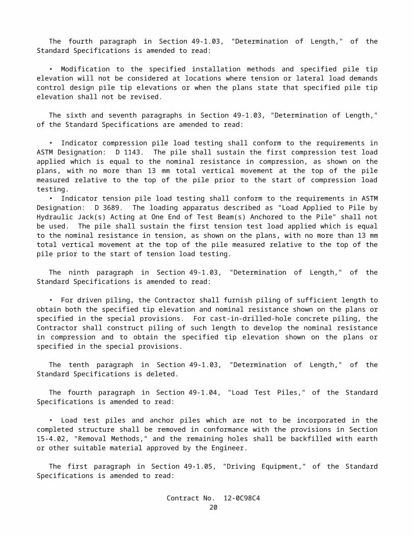
• Where ASTM Designations: A 615/A 615M, Grade 420 or A 706/A 706M reinforcing bars are required, the length of lap splices shall be as follows: Reinforcing bars No. 25 or smaller shall be lapped at least 45 diameters of the smaller bar joined; and reinforcing bars Nos. 29, 32, and 36 shall be lapped at least 60 diameters of the smaller bar joined, except when otherwise shown on the plans.
• Where ASTM Designation: A 615/A 615M, Grade 280 reinforcing bars are permitted, the length of lap splices shall be as follows: Reinforcing bars No. 25 or smaller shall be lapped at least 30 diameters of the smaller bar joined; and reinforcing bars Nos. 29, 32, and 36 shall be lapped at least 45 diameters of the smaller bar joined, except when otherwise shown on the plans.
• Splices in bundled bars shall conform to the following:
A In bundles of 2 bars, the length of the lap splice shall be the same as the length of a single bar lap splice.B. In bundles of 3 bars, the length of the lap splice shall be 1.2 times the length of a single bar lap splice.
• Welded wire fabric shall be lapped such that the overlap between the outermost cross wires is not less than the larger of:
A. 150 mm,B. The spacing of the cross wires plus 50 mm, orC. The numerical value of the longitudinal wire size (MW-Size Number) times 370 divided by the spacing of the
longitudinal wires in millimeters.
52-1.08B Service Splicing and Ultimate Butt Splicing Requirements• Service splices and ultimate butt splices shall be either butt welded or mechanical splices, shall be used at the
locations shown on the plans, and shall conform to the requirements of these specifications and the special provisions.
52-1.08B(1) Mechanical Splices• Mechanical splices to be used in the work shall be on the Department's current prequalified list before use. The
prequalified list can be obtained from the Department's internet site listed in the special provisions or by contacting the Transportation Laboratory directly.
• When tested in conformance with the requirements in California Test 670, the total slip of the reinforcing bars within the splice device after loading in tension to 200 MPa and relaxing to 20 MPa shall not exceed the values listed in the following table. The slip shall be measured between gage points that are clear of the splice device.
Reinforcing Bar Number Total Slip (µm)13 25016 25019 25022 35025 35029 35032 45036 45043 60057 750
• Slip requirements shall not apply to mechanical lap splices, splices that are welded, or splices that are used on hoops.
• Splicing procedures shall be in conformance with the manufacturer's recommendations, except as modified in this section. Splices shall be made using the manufacturer's standard equipment, jigs, clamps, and other required accessories.
• Splice devices shall have a clear coverage of not less than 40 mm measured from the surface of the concrete to the outside of the splice device. Stirrups, ties, and other reinforcement shall be adjusted or relocated, and additional reinforcement shall be placed, if necessary, to provide the specified clear coverage to reinforcement.
• The Contractor shall furnish the following information for each shipment of splice material in conformance with the provisions in Section 6-1.07, "Certificates of Compliance:"
A. The type or series identification of the splice material including tracking information for traceability.B. The bar grade and size number to be spliced.
Contract No. 12-0C98C422

C. A copy of the manufacturer's product literature giving complete data on the splice material and installation procedures.
D. A statement that the splicing systems and materials used in conformance with the manufacturer's installation procedures will develop the required tensile strengths, based on the nominal bar area, and will conform to the total slip requirements and the other requirements in these specifications.
E. A statement that the splice material conforms to the type of mechanical splice in the Department's current prequalified list.
52-1.08B(2) Butt Welded Splices• Except for resistance butt welds, butt welded splices of reinforcing bars shall be complete joint penetration butt
welds conforming to the requirements in AWS D 1.4, and these specifications.• Welders and welding procedures shall be qualified in conformance with the requirements in AWS D 1.4.• Only the joint details and dimensions as shown in Figure 3.2, "Direct Butt Joints," of AWS D 1.4, shall be used for
making complete joint penetration butt welds of bar reinforcement. Split pipe backing shall not be used.• Butt welds shall be made with multiple weld passes using a stringer bead without an appreciable weaving motion.
The maximum stringer bead width shall be 2.5 times the diameter of the electrode and slagging shall be performed between each weld pass. Weld reinforcement shall not exceed 4 mm in convexity.
• Electrodes used for welding shall meet the minimum Charpy V-notch impact requirement of 27°J at –20°C.• For welding of bars conforming to the requirements of ASTM Designation: A 615/A 615M, Grade 280 or
Grade 420, the requirements of Table 5.2, "Minimum Preheat and Interpass Temperatures," of AWS D 1.4 are superseded by the following:
The minimum preheat and interpass temperatures shall be 200°C for Grade 280 bars and 300°C for Grade 420 bars. Immediately after completing the welding, at least 150 mm of the bar on each side of the splice shall be covered by an insulated wrapping to control the rate of cooling. The insulated wrapping shall remain in place until the bar has cooled below 90°C.
• When welding different grades of reinforcing bars, the electrode shall conform to Grade 280 bar requirements and the preheat shall conform to the Grade 420 bar requirements.
• In the event that any of the specified preheat, interpass, and post weld cooling temperatures are not met, all weld and heat affected zone metal shall be removed and the splice rewelded.
• Welding shall be protected from air currents, drafts, and precipitation to prevent loss of heat or loss of arc shielding. The method of protecting the welding area from loss of heat or loss of arc shielding shall be subject to approval by the Engineer.
• Reinforcing bars shall not be direct butt spliced by thermite welding.• Procedures to be used in making welded splices in reinforcing bars, and welders employed to make splices in
reinforcing bars, shall be qualified by tests performed by the Contractor on sample splices of the type to be used, before making splices to be used in the work.
52-1.08B(3) Resistance Butt Welds• Shop produced resistance butt welds shall be produced by a fabricator who is approved by the Transportation
Laboratory. The list of approved fabricators can be obtained from the Department’s internet site or by contacting the Transportation Laboratory directly.
• Before manufacturing hoops using resistance butt welding, the Contractor shall submit to the Engineer the manufacturer's Quality Control (QC) manual for the fabrication of hoops. As a minimum, the QC manual shall include the following:
A. The pre-production procedures for the qualification of material and equipment.B. The methods and frequencies for performing QC procedures during production.C. The calibration procedures and calibration frequency for all equipment.D. The welding procedure specification (WPS) for resistance welding.E. The method for identifying and tracking lots.
52-1.08C Service Splice and Ultimate Butt Splice Testing Requirements• The Contractor shall designate in writing a splicing Quality Control Manager (QCM). The QCM shall be
responsible directly to the Contractor for 1) the quality of all service and ultimate butt splicing including the inspection of materials and workmanship performed by the Contractor and all subcontractors; and 2) submitting, receiving, and approving all correspondence, required submittals, and reports regarding service and ultimate splicing to and from the Engineer.
Contract No. 12-0C98C423
• The QCM shall not be employed or compensated by any subcontractor, or by other persons or entities hired by subcontractors, who will provide other services or materials for the project. The QCM may be an employee of the Contractor.
• Testing on prequalification and production sample splices shall be performed at the Contractor's expense, at an independent qualified testing laboratory. The laboratory shall not be employed or compensated by any subcontractor, or by other persons or entities hired by subcontractors who will provide other services or materials for the project, and shall have the following:
A. Proper facilities, including a tensile testing machine capable of breaking the largest size of reinforcing bar to be tested with minimum lengths as shown in this section.
B. A device for measuring the total slip of the reinforcing bars across the splice to the nearest 25 µm, that, when placed parallel to the longitudinal axis of the bar is able to simultaneously measure movement across the splice, at 2 locations, 180 degrees apart.
C. Operators who have received formal training for performing the testing requirements of ASTM Designation: A 370 and California Test 670.
D. A record of annual calibration of testing equipment performed by an independent third party that has 1) standards that are traceable to the National Institute of Standards and Technology, and 2) a formal reporting procedure, including published test forms.
• The Contractor shall provide samples for quality assurance testing in conformance with the provisions in these specifications and the special provisions.
• Prequalification and production sample splices shall be 1) a minimum length of 1.5 meters for reinforcing bars No. 25 or smaller, and 2 meters for reinforcing bars No. 29 or larger, with the splice located at mid-point; and 2) suitably identified before shipment with weatherproof markings that do not interfere with the Engineer's tamper-proof markings or seals. Splices that shows signs of tampering will be rejected.
• Each set or sample splice, as defined herein, shall be identified as representing either a prequalification or production test sample splice.
• For the purpose of production testing, a lot of either service splices or ultimate butt splices is defined as 1) 150, or fraction thereof, of the same type of mechanical splices used for each bar size and each bar deformation pattern that is used in the work, or 2) 150, or fraction thereof, of complete joint penetration butt welded splices, or resistance butt welded splices for each bar size used in the work. If different diameters of hoop reinforcement are shown on the plans, separate lots shall be used for each different hoop diameter.
• Whenever a lot of splices is rejected, the rejected lot and subsequent lots of splices shall not be used in the work until 1) the QCM performs a complete review of the Contractor's quality control process for these splices, 2) a written report is submitted to the Engineer describing the cause of failure for the splices in this lot and provisions for preventing similar failures in future lots, and 3) the Engineer has provided the Contractor with written notification that the report is acceptable. The Engineer shall have 3 working days after receipt of the report to provide notification to the Contractor. In the event the Engineer fails to provide notification within the time allowed, and if, in the opinion of the Engineer, completion of the work is delayed or interfered with by reason of the Engineer's delay in providing notification, the Contractor will be compensated for any resulting loss, and an extension of time will be granted in the same manner as provided for in Section 8-1.09, "Right of Way Delays."
52-1.08C(1) Splice Prequalification Report• Before using any service splices or ultimate butt splices in the work, the Contractor shall submit a Splice
Prequalification Report. The report shall include splice material information, names of the operators who will be performing the splicing, and descriptions of the positions, locations, equipment, and procedures that will be used in the work.
• The Splice Prequalification Report shall also include certifications from the fabricator for prequalifications of operators and procedures based on sample tests performed no more than 2 years before submitting the report. Each operator shall be certified by performing 2 sample splices for each bar size of each splice type that the operator will be performing in the work. For deformation-dependent types of splice devices, each operator shall be certified by performing 2 additional samples for each bar size and deformation pattern that will be used in the work.
• Prequalification sample splices shall be tested by an independent qualified testing laboratory and shall conform to the appropriate production test criteria and slip requirements specified herein. When epoxy-coated reinforcement is required, resistance butt welded sample splices shall have the weld flash removed by the same procedure as will be used in the work, before coating and testing. The Splice Prequalification Report shall include the certified test results for all prequalification sample splices.
• The QCM shall review and approve the Splice Prequalification Report before submitting it to the Engineer for approval. The Contractor shall allow 2 weeks for the review and approval of a complete report before performing any
Contract No. 12-0C98C424
service splicing or ultimate butt splicing in the work. In the event the Engineer fails to complete the review within the time allowed, and in the opinion of the Engineer, completion of the work is delayed or interfered with by reason of the Engineer's delay in completing the review, the Contractor will be compensated for any resulting loss, and an extension of time will be granted, in the same manner as provided for in Section 8-1.09, "Right of Way Delays."
52-1.08C(2) Service Splice Test Criteria• Service production and quality assurance sample splices shall be tensile tested in conformance with the requirements
in ASTM Designation: A 370 and California Test 670 and shall develop a minimum tensile strength of not less than 550 MPa.
52-1.08C(2)(a) Production Test Requirements for Service Splices• Production tests shall be performed by the Contractor's independent laboratory for all service splices used in the
work. A production test shall consist of testing 4 sample splices prepared for each lot of completed splices. The samples shall be prepared by the Contractor using the same splice material, position, operators, location, and equipment, and following the same procedure as used in the work.
• At least one week before testing, the Contractor shall notify the Engineer in writing of the date when and the location where the testing of the samples will be performed.
• The 4 samples from each production test shall be securely bundled together and identified with a completed sample identification card before shipment to the independent laboratory. The card will be furnished by the Engineer. Bundles of samples containing fewer than 4 samples of splices shall not be tested.
• Before performing any tensile tests on production test sample splices, one of the 4 samples shall be tested for, and shall conform to, the requirements for total slip. Should this sample not meet the total slip requirements, one retest, in which the 3 remaining samples are tested for total slip, will be allowed. Should any of the 3 remaining samples not conform to the total slip requirements, all splices in the lot represented by this production test will be rejected.
• If 3 or more sample splices from a production test conform to the provisions in this Section 52-1.08C(2),"Service Splice Test Criteria," all splices in the lot represented by this production test will be considered acceptable, provided each of the 4 samples develop a minimum tensile strength of not less than 420 MPa.
• Should only 2 sample splices from a production test conform to the provisions in this Section 52-1.08C(2), "Service Splice Test Criteria," one additional production test shall be performed on the same lot of splices. This additional production test shall consist of testing 4 samples splices that have been randomly selected by the Engineer and removed by the Contractor from the actual completed lot of splices. Should any of the 4 splices from this additional test fail to conform to these provisions, all splices in the lot represented by these production tests will be rejected.
• If only one sample splice from a production test conforms to the provisions in this Section 52-1.08C(2), "Service Splice Test Criteria," all splices in the lot represented by this production test will be rejected.
• If a production test for a lot fails, the Contractor shall repair or replace all reinforcing bars from which sample splices were removed before the Engineer selects additional splices from this lot for further testing.
52-1.08C(2)(b) Quality Assurance Test Requirements for Service Splices• For the first production test performed, and for at least one, randomly selected by the Engineer, of every
5 subsequent production tests, or portion thereof, the Contractor shall concurrently prepare 4 additional service quality assurance sample splices. These service quality assurance sample splices shall be prepared in the same manner as specified herein for service production sample splices.
• These 4 additional quality assurance sample splices shall be shipped to the Transportation Laboratory for quality assurance testing. The 4 sample splices shall be securely bundled together and identified by location and contract number with weatherproof markings before shipment. Bundles containing fewer than 4 samples of splices will not be tested. Sample splices not accompanied by the supporting documentation required in Section 52-1.08B(1), for mechanical splices, or in Section 52-1.08B(3), for resistance butt welds, will not be tested.
• Quality assurance testing will be performed in conformance with the requirements for service production sample splices in Section 52-1.08C(2)(a), "Production Test Requirements for Service Splices."
52-1.08C(3) Ultimate Butt Splice Test Criteria• Ultimate production and quality assurance sample splices shall be tensile tested in conformance with the
requirements described in ASTM Designation: A 370 and California Test 670.• A minimum of one control bar shall be removed from the same bar as, and adjacent to, all ultimate production, and
quality assurance sample splices. Control bars shall be 1) a minimum length of one meter for reinforcing bars No. 25 or smaller and 1.5 meters for reinforcing bars No. 29 or larger, and 2) suitably identified before shipment with weatherproof markings that do not interfere with the Engineer's tamper-proof markings or seals. The portion of adjacent bar remaining in the work shall also be identified with weatherproof markings that correspond to its adjacent control bar.
Contract No. 12-0C98C425

• Each sample splice and its associated control bar shall be identified and marked as a set. Each set shall be identified as representing a prequalification, production, or quality assurance sample splice.
• The portion of hoop reinforcing bar, removed to obtain a sample splice and control bar, shall be replaced using a prequalified ultimate mechanical butt splice, or the hoop shall be replaced in kind.
• Reinforcing bars, other than hoops, from which sample splices are removed, shall be repaired using ultimate mechanical butt splices conforming to the provisions in Section 52-1.08C(1), "Splice Prequalification Report," or the bars shall be replaced in kind. These bars shall be repaired or replaced such that no splices are located in any "No Splice Zone" shown on the plans.
• Ultimate production and quality assurance sample splices shall rupture in the reinforcing bar either: 1) outside of the affected zone or 2) within the affected zone, provided that the sample splice has achieved at least 95 percent of the ultimate tensile strength of the control bar associated with the sample splice. In addition, necking of the bar shall be visibly evident at rupture regardless of whether the bar breaks inside or outside the affected zone.
• The affected zone is the portion of the reinforcing bar where any properties of the bar, including the physical, metallurgical, or material characteristics, have been altered by fabrication or installation of the splice.
• The ultimate tensile strength shall be determined for all control bars by tensile testing the bars to rupture, regardless of where each sample splice ruptures. If 2 control bars are tested for one sample splice, the bar with the lower ultimate tensile strength shall be considered the control bar.
52-1.08C(3)(a) Production Test Requirements for Ultimate Butt Splices• Production tests shall be performed for all ultimate butt splices used in the work. A production test shall consist of
testing 4 sets of sample splices and control bars removed from each lot of completed splices, except when quality assurance tests are performed.
• After the splices in a lot have been completed, and the bars have been epoxy-coated when required, the QCM shall notify the Engineer in writing that the splices in this lot conform to the specifications and are ready for testing. Except for hoops, sample splices will be selected by the Engineer at the job site. Sample splices for hoops will be selected by the Engineer either at the job site or a fabrication facility.
• After notification has been received, the Engineer will randomly select the 4 sample splices to be removed from the lot and place tamper-proof markings or seals on them. The Contractor shall select the adjacent control bar for each sample splice bar, and the Engineer will place tamper-proof markings or seals on them. These ultimate production sample splices and control bars shall be removed by the Contractor, and tested by an independent qualified testing laboratory.
• At least one week before testing, the Contractor shall notify the Engineer in writing of the date when and the location where the testing of the samples will be performed.
• A sample splice or control bar from any set will be rejected if a tamper-proof marking or seal is disturbed before testing.
• The 4 sets from each production test shall be securely bundled together and identified with a completed sample identification card before shipment to the independent laboratory. The card will be furnished by the Engineer. Bundles of samples containing fewer than 4 sets of splices shall not be tested.
• Before performing any tensile tests on production test sample splices, one of the 4 sample splices shall be tested for, and shall conform to, the requirements for total slip. Should this sample splice not meet these requirements, one retest, in which the 3 remaining sample splices are tested for total slip, will be allowed. Should any of the 3 remaining sample splices not conform to these requirements, all splices in the lot represented by this production test will be rejected.
• If 3 or more sample splices from a production test conform to the provisions in Section 52-1.08C(3), "Ultimate Butt Splice Test Criteria," all splices in the lot represented by this production test will be considered acceptable.
• Should only 2 sample splices from a production test conform to the provisions in Section 52-1.08C(3), "Ultimate Butt Splice Test Criteria," one additional production test shall be performed on the same lot of splices. Should any of the 4 sample splices from this additional test fail to conform to these provisions, all splices in the lot represented by these production tests will be rejected.
• If only one sample splice from a production test conforms to the provisions in Section 52-1.08C(3), "Ultimate Butt Splice Test Criteria," all splices in the lot represented by this production test will be rejected.
• If a production test for a lot fails, the Contractor shall repair or replace all reinforcing bars from which sample splices were removed, complete in place, before the Engineer selects additional splices from this lot for further testing.
• Production tests will not be required on repaired splices from a lot, regardless of the type of prequalified ultimate mechanical butt splice used to make the repair. However, should an additional production test be required, the Engineer may select any repaired splice for the additional production test.
52-1.08C(3)(b) Quality Assurance Test Requirements for Ultimate Butt Splices
Contract No. 12-0C98C426

• For the first production test performed, and for at least one, randomly selected by the Engineer, of every 5 subsequent production tests, or portion thereof, the Contractor shall concurrently prepare 4 additional ultimate quality assurance sample splices along with associated control bars.
• Each time 4 additional ultimate quality assurance sample splices are prepared, 2 of these quality assurance sample splice and associated control bar sets and 2 of the production sample splice and associated control bar sets, together, shall conform to the requirements for ultimate production sample splices in Section 52-1.08C(3)(a),"Production Test Requirements for Ultimate Butt Splices."
• The 2 remaining quality assurance sample splice and associated control bar sets, along with the 2 remaining production sample splice and associated control bar sets shall be shipped to the Transportation Laboratory for quality assurance testing. The 4 sets shall be securely bundled together and identified by location and contract number with weatherproof markings before shipment. Bundles containing fewer than 4 sets will not be tested.
• Quality assurance testing will be performed in conformance with the requirements for ultimate production sample splices in Section 52-1.08C(3)(a), "Production Test Requirements for Ultimate Butt Splices."
52-1.08C(3)(c) Nondestructive Splice Tests• When the specifications allow for welded sample splices to be taken from other than the completed lot of splices, the
Contractor shall meet the following additional requirements.• Except for resistance butt welded splices, radiographic examinations shall be performed on 25 percent of all
complete joint penetration butt welded splices from a production lot. The size of a production lot will be a maximum of 150 splices. The Engineer will select the splices which will compose the production lot and also the splices within each production lot to be radiographically examined.
• All required radiographic examinations of complete joint penetration butt welded splices shall be performed by the Contractor in conformance with the requirements in AWS D 1.4 and these specifications.
• Before radiographic examination, welds shall conform to the requirements in Section 4.4, "Quality of Welds," of AWS D 1.4.
• Should more than 12 percent of the splices which have been radiographically examined in any production lot be defective, an additional 25 percent of the splices, selected by the Engineer from the same production lot, shall be radiographically examined. Should more than 12 percent of the cumulative total of splices tested from the same production lot be defective, all remaining splices in the lot shall be radiographically examined.
• Additional radiographic examinations performed due to the identification of defective splices shall be at the Contractor's expense.
• All defects shall be repaired in conformance with the requirements in AWS D 1.4.• The Contractor shall notify the Engineer in writing 48 hours before performing any radiographic examinations.• The radiographic procedure used shall conform to the requirements in AWS D1.1, AWS D1.4, and the following:
Two exposures shall be made for each complete joint penetration butt welded splice. For each of the 2 exposures, the radiation source shall be centered on each bar to be radiographed. The first exposure shall be made with the radiation source placed at zero degrees from the top of the weld and perpendicular to the weld root and identified with a station mark of "0." The second exposure shall be at 90 degrees to the "0" station mark and shall be identified with a station mark of "90." When obstructions prevent a 90 degree placement of the radiation source for the second exposure, and when approved in writing by the Engineer, the source may be rotated, around the centerline of the reinforcing bar, a maximum of 25 degrees.
For field produced complete joint penetration butt welds, no more than one weld shall be radiographed during one exposure. For shop produced complete joint penetration butt welds, if more than one weld is to be radiographed during one exposure, the angle between the root line of each weld and the direction to the radiation source shall be not less than 65 degrees.
Radiographs shall be made by either X-ray or gamma ray. Radiographs made by X-ray or gamma rays shall have densities of not less than 2.3 nor more than 3.5 in the area of interest. A tolerance of 0.05 in density is allowed for densitometer variations. Gamma rays shall be from the iridium 192 isotope and the emitting specimen shall not exceed 4.45 mm in the greatest diagonal dimension.
The radiographic film shall be placed perpendicular to the radiation source at all times; parallel to the root line of the weld unless source placement determines that the film must be turned; and as close to the root of the weld as possible.
The minimum source to film distance shall be maintained so as to ensure that all radiographs maintain a maximum geometric unsharpness of 0.020 at all times, regardless of the size of the reinforcing bars.
Penetrameters shall be placed on the source side of the bar and perpendicular to the radiation source at all times. One penetrameter shall be placed in the center of each bar to be radiographed, perpendicular to the weld root, and adjacent to the weld. Penetrameter images shall not appear in the weld area.
Contract No. 12-0C98C427
When radiography of more than one weld is being performed per exposure, each exposure shall have a minimum of one penetrameter per bar, or 3 penetrameters per exposure. When 3 penetrameters per exposure are used, one penetrameter shall be placed on each of the 2 outermost bars of the exposure, and the remaining penetrameter shall be placed on a centrally located bar.
An allowable weld buildup of 4 mm may be added to the total material thickness when determining the proper penetrameter selection. No image quality indicator equivalency will be accepted. Wire penetrameters or penetrameter blocks shall not be used.
Penetrameters shall be sufficiently shimmed using a radiographically identical material. Penetrameter image densities shall be a minimum of 2.0 and a maximum of 3.6.
Radiographic film shall be Class 1, regardless of the size of reinforcing bars.Radiographs shall be free of film artifacts and processing defects, including, but not limited to, streaks, scratches,
pressure marks or marks made for the purpose of identifying film or welding indications.Each splice shall be clearly identified on each radiograph and the radiograph identification and marking system shall
be established between the Contractor and the Engineer before radiographic inspection begins. Film shall be identified by lead numbers only; etching, flashing or writing in identifications of any type will not be permitted. Each piece of film identification information shall be legible and shall include, as a minimum, the following information: Contractor's name, date, name of nondestructive testing firm, initials of radiographer, contract number, part number and weld number. The letter "R" and repair number shall be placed directly after the weld number to designate a radiograph of a repaired weld.
Radiographic film shall be developed within a time range of one minute less to one minute more than the film manufacturer's recommended maximum development time. Sight development will not be allowed.
Processing chemistry shall be done with a consistent mixture and quality, and processing rinses and tanks shall be clean to ensure proper results. Records of all developing processes and any chemical changes to the developing processes shall be kept and furnished to the Engineer upon request. The Engineer may request, at any time, that a sheet of unexposed film be processed in the presence of the Engineer to verify processing chemical and rinse quality.
The results of all radiographic interpretations shall be recorded on a signed certification and a copy kept with the film packet.
Technique sheets prepared in conformance with the requirements in ASME Boiler and Pressure Vessels Code, Section V, Article 2 Section T-291 shall also contain the developer temperature, developing time, fixing duration and all rinse times.
52-1.08D Reporting Test Results• A Production Test Report for all testing performed on each lot shall be prepared by the independent testing
laboratory performing the testing and submitted to the QCM for review and approval. The report shall be signed by an engineer who represents the laboratory and is registered as a Civil Engineer in the State of California. The report shall include, as a minimum, the following information for each test: contract number, bridge number, lot number and location, bar size, type of splice, length of mechanical splice, length of test specimen, physical condition of test sample splice and any associated control bar, any notable defects, total measured slip, ultimate tensile strength of each splice, and for ultimate butt splices, limits of affected zone, location of visible necking area, ultimate tensile strength and 95 percent of this ultimate tensile strength for each control bar, and a comparison between 95 percent of the ultimate tensile strength of each control bar and the ultimate tensile strength of its associated splice.
• The QCM must review, approve, and forward each Production Test Report to the Engineer for review before the splices represented by the report are encased in concrete. The Engineer will have 3 working days to review each Production Test Report and respond in writing after a complete report has been received. Should the Contractor elect to encase any splices before receiving notification from the Engineer, it is expressly understood that the Contractor will not be relieved of the responsibility for incorporating material in the work that conforms to the requirements of the plans and specifications. Material not conforming to these requirements will be subject to rejection. Should the Contractor elect to wait to encase splices pending notification by the Engineer, and in the event the Engineer fails to complete the review and provide notification within the time allowed, and if, in the opinion of the Engineer, the work is delayed or interfered with by reason of the Engineer's delay in completing the review, the Contractor will be compensated for any resulting loss, and an extension of time will be granted, in the same manner as provided for in Section 8-1.09, "Right of Way Delays."
• Quality assurance test results for each bundle of 4 sets or 4 samples of splices will be reported in writing to the Contractor within 3 working days after receipt of the bundle by the Transportation Laboratory. In the event that more than one bundle is received on the same day, 2 additional working days shall be allowed for providing test results for each additional bundle received. A test report will be made for each bundle received. Should the Contractor elect to encase splices before receiving notification from the Engineer, it is expressly understood that the Contractor will not be relieved of the responsibility for incorporating material in the work that conforms to the requirements of the plans and specifications. Material not conforming to these requirements will be subject to rejection. Should the Contractor elect to wait to encase
Contract No. 12-0C98C428

splices pending notification by the Engineer, and in the event the Engineer fails to complete the review within the time allowed, and in the opinion of the Engineer, completion of the work is delayed or interfered with by reason of the Engineer's delay in completing the review, the Contractor will be compensated for any resulting loss, and an extension of time will be granted, in the same manner as provided for in Section 8-1.09, "Right of Way Delays."
Contract No. 12-0C98C429

SECTION 55: STEEL STRUCTURES
Issue Date: December 31, 2001
Section 55-3.14, "Bolted Connections," of the Standard Specifications is amended by adding the following after the ninth paragraph:
• If a torque multiplier is used in conjunction with a calibrated wrench as a method for tightening fastener assemblies to the required tension, both the multiplier and the wrench shall be calibrated together as a system. The same length input and output sockets and extensions that will be used in the work shall also be included in the calibration of the system. The manufacturer's torque multiplication ratio shall be adjusted during calibration of the system, such that when this adjusted ratio is multiplied by the actual input calibrated wrench reading, the product is a calculated output torque that is within 2 percent of the true output torque. When this system is used in the work to perform any installation tension testing, rotational capacity testing, fastener tightening, or tension verification, it shall be used, intact as calibrated.
The sixth paragraph of Section 55-4.02, "Payment," of the Standard Specifications is amended to read:
• If a portion or all of the structural steel is fabricated more than 480 air line kilometers from both Sacramento and Los Angeles, additional shop inspection expenses will be sustained by the State. Whereas it is and will be impracticable and extremely difficult to ascertain and determine the actual increase in these expenses, it is agreed that payment to the Contractor for furnishing the structural steel from each fabrication site located more than 480 air line kilometers from both Sacramento and Los Angeles will be reduced $5000 or by an amount computed at $0.044 per kilogram of structural steel fabricated, whichever is greater, or in the case of each fabrication site located more than 4800 air line kilometers from both Sacramento and Los Angeles, payment will be reduced $8000 or by $0.079 per kilogram of structural steel fabricated, whichever is greater.
SECTION 56: SIGNS
Issue Date: December 31, 2001
Section 56-1.01, "Description," of the Standard Specifications is amended by deleting the third paragraph.
The sixth through the thirteenth paragraphs in Section 56-1.03, "Fabrication," of the Standard Specifications are amended to read:
• High-strength bolted connections, where shown on the plans, shall conform to the provisions in Section 55-3.14, "Bolted Connections," except that only fastener assemblies consisting of a high-strength bolt, nut, hardened washer, and direct tension indicator shall be used.
• High-strength fastener assemblies, and any other bolts, nuts, and washers attached to sign structures shall be zinc-coated by the mechanical deposition process.
• An alternating snugging and tensioning pattern for anchor bolts and high-strength bolted splices shall be used. Once tensioned, high-strength fastener components and direct tension indicators shall not be reused.
• For bolt diameters less than 10 mm, the diameter of the bolt hole shall be not more than 0.80-mm larger than the nominal bolt diameter. For bolt diameters greater than or equal to 10 mm, the diameter of the bolt hole shall be not more than 1.6 mm larger than the nominal bolt diameter.
• Sign structures shall be fabricated into the largest practical sections prior to galvanizing.• Ribbed sheet metal panels for box beam closed truss sign structures shall be fastened to the truss members by cap
screws or bolts as shown on the plans, or by 4.76 mm stainless steel blind rivets conforming to Industrial Fasteners Institute, Standard IFI-114, Grade 51. The outside diameter of the large flange rivet head shall be not less than 15.88 mm in diameter. Web splices in ribbed sheet metal panels may be made with similar type blind rivets of a size suitable for the thickness of material being connected.
• Spalling or chipping of concrete structures shall be repaired by the Contractor at the Contractor's expense.• Overhead sign supports shall have an aluminum identification plate permanently attached near the base, adjacent to
the traffic side on one of the vertical posts, using either stainless steel rivets or stainless steel screws. As a minimum, the information on the plate shall include the name of the manufacturer, the date of manufacture and the contract number.
Contract No. 12-0C98C430

SECTION 59: PAINTING
Issue Date: December 31, 2001
Section 59-2.01, "General," of the Standard Specifications is amended by adding the following paragraphs after the first paragraph:
• Unless otherwise specified, no painting Contractors or subcontractors will be permitted to commence work without having the following current "SSPC: The Society for Protective Coatings" (formerly the Steel Structures Painting Council) certifications in good standing:
A. For cleaning and painting structural steel in the field, certification in conformance with the requirements in Qualification Procedure No. 1, "Standard Procedure For Evaluating Painting Contractors (Field Application to Complex Industrial Structures)" (SSPC-QP 1).
B. For removing paint from structural steel, certification in conformance with the requirements in Qualification Procedure No. 2, "Standard Procedure For Evaluating Painting Contractors (Field Removal of Hazardous Coatings from Complex Structures)" (SSPC-QP 2).
C. For cleaning and painting structural steel in a permanent painting facility, certification in conformance with the requirements in Qualification Procedure No. 3, "Standard Procedure For Evaluating Qualifications of Shop Painting Applicators" (SSPC-QP 3). The AISC's Sophisticated Paint Endorsement (SPE) quality program will be considered equivalent to SSPC-QP 3.
The third paragraph of Section 59-2.03, "Blast Cleaning," of the Standard Specifications is amended to read:
• Exposed steel or other metal surfaces to be blast cleaned shall be cleaned in conformance with the requirements in Surface Preparation Specification No. 6, "Commercial Blast Cleaning," of the "SSPC: The Society for Protective Coatings." Blast cleaning shall leave all surfaces with a dense, uniform, angular anchor pattern of not less than 35 µm as measured in conformance with the requirements in ASTM Designation: D 4417.
The first paragraph of Section 59-2.06, "Hand Cleaning," of the Standard Specifications is amended to read:
• Dirt, loose rust and mill scale, or paint which is not firmly bonded to the surfaces shall be removed in conformance with the requirements in Surface Preparation Specification No. 2, "Hand Tool Cleaning," of the "SSPC: The Society for Protective Coatings." Edges of old remaining paint shall be feathered.
The fourth paragraph of Section 59-2.12, "Painting," of the Standard Specifications is amended to read:
• The dry film thickness of the paint will be measured in place with a calibrated Type 2 magnetic film thickness gage in conformance with the requirements of specification SSPC-PA2 of the "SSPC: The Society for Protective Coatings."
SECTION 75: MISCELLANEOUS METAL
Issue Date: December 31, 2001
The table in the tenth paragraph of Section 75-1.02, "Miscellaneous Iron and Steel," of the Standard Specifications is amended to read:
Contract No. 12-0C98C431

Material SpecificationSteel bars, plates and shapes
ASTM Designation: A 36/A 36M or A 575, A 576 (AISI or M Grades 1016 through 1030 except Grade 1017)
Steel fastener components for general applications:Bolts and studs ASTM Designation: A 307Headed anchor bolts ASTM Designation: A 307, Grade B, including
S1 supplementary requirementsNonheaded anchor bolts
ASTM Designation: A 307, Grade C, including S1 supplementary requirements and S1.6 of AASHTO Designation: M 314 supplementary requirementsor AASHTO Designation: M 314, Grade 36 or 55, including S1 supplementary requirements
High-strength bolts and studs, threaded rods, and nonheaded anchor bolts
ASTM Designation: A 449, Type 1
Nuts ASTM Designation: A 563, including Appendix X1*
Washers ASTM Designation: F 844Components of high-strength steel fastener assemblies for use in structural steel joints:
Bolts ASTM Designation: A 325, Type 1Tension control bolts ASTM Designation: F 1852, Type 1Nuts ASTM Designation: A 563, including
Appendix X1*Hardened washers ASTM Designation: F 436, Type 1, Circular,
including S1 supplementary requirementsDirect tension indicators
ASTM Designation: F 959, Type 325, zinc-coated
Stainless steel fasteners (Alloys 304 & 316) for general applications:Bolts, screws, studs, threaded rods, and nonheaded anchor bolts
ASTM Designation: F 593 or F 738M
Nuts ASTM Designation: F 594 or F 836MWashers ASTM Designation: A 240/A 240M and
ANSI B 18.22MCarbon-steel castings ASTM Designation: A 27/A 27M, Grade 65-35
[450-240], Class 1Malleable iron castings ASTM Designation: A 47, Grade 32510 or
A 47M, Grade 22010Gray iron castings ASTM Designation: A 48, Class 30BDuctile iron castings ASTM Designation: A 536, Grade 65-45-12Cast iron pipe Commercial qualitySteel pipe Commercial quality, welded or extrudedOther parts for general applications
Commercial quality
* Zinc-coated nuts that will be tightened beyond snug or wrench tight shall be furnished with a dyed dry lubricant conforming to Supplementary Requirement S2 in ASTM Designation: A 563.
The table in the eighteenth paragraph of Section 75-1.03, "Miscellaneous Bridge Metal," of the Standard Specifications is amended to read:
Contract No. 12-0C98C432

Stud Diameter(millimeters)
Sustained TensionTest Load
(kilonewtons)29.01-33.00 137.923.01-29.00 79.621.01-23.00 64.1
* 18.01-21.00 22.215.01-18.00 18.212.01-15.00 14.29.01-12.00 9.346.00-9.00 4.23
* Maximum stud diameter permitted for mechanical expansion anchors.
The table in the nineteenth paragraph of Section 75-1.03, "Miscellaneous Bridge Metal," of the Standard Specifications is amended to read:
Stud Diameter(millimeters)
UltimateTensile Load(kilonewtons)
30.01-33.00 112.127.01-30.00 88.123.01-27.00 71.220.01-23.00 51.616.01-20.00 32.014.01-16.00 29.412.00-14.00 18.7
The table in the twenty-second paragraph of Section 75-1.03, "Miscellaneous Bridge Metal," of the Standard Specifications is amended to read:
Installation Torque Values, (newton meters)
Stud Diameter(millimeters)
Shell TypeMechanicalExpansionAnchors
Integral Stud TypeMechanicalExpansionAnchors
Resin Capsule Anchors
andCast-in-Place Inserts
29.01-33.00 — — 54023.01-29.00 — — 31521.01-23.00 — — 23518.01-21.00 110 235 20015.01-18.00 45 120 10012.01-15.00 30 65 40 9.01-12.00 15 35 246.00-9.00 5 10 —
SECTION 83: RAILINGS AND BARRIERS
Issue Date: June 13, 2002
The ninth paragraph in Section 83-1.02B, "Metal Beam Guard Railing," of the Standard Specifications is amended to read:
• The grades and species of wood posts and blocks shall be No. 1 timbers (also known as No. 1 structural) Douglas fir or No. 1 timbers Southern yellow pine. Wood posts and blocks shall be graded in conformance with the provisions in Section 57-2, "Structural Timber," of the Standard Specifications, except allowances for shrinkage after mill cutting shall in no case exceed 5 percent of the American Lumber Standards minimum sizes, at the time of installation.
Contract No. 12-0C98C433
The eleventh paragraph in Section 83-1.02B, "Metal Beam Guard Railing," of the Standard Specifications is amended to read:
• Wood posts and blocks shall be pressure treated after fabrication in conformance with the provisions in Section 58, "Preservative Treatment of Lumber, Timber and Piling," of the Standard Specifications with creosote, creosote coal tar solution, creosote petroleum solution (50-50), pentachlorophenol in hydrocarbon solvent, copper naphthenate, ammoniacal copper arsenate, or ammoniacal copper zinc arsenate. In addition to the preservatives listed above, Southern yellow pine may also be pressure treated with chromated copper arsenate. When other than one of the creosote processes is used, blocks shall have a minimum retention of 6.4 Kg/m3, and need not be incised.
SECTION 85: PAVEMENT MARKERS
Issue Date: May 16, 2003
The second through fifth paragraphs in Section 85-1.03, "Sampling, Tolerances and Packaging," of the Standard Specifications are amended to read:
Sampling• Twenty markers selected at random will constitute a representative sample for each lot of markers.• The lot size shall not exceed 25000 markers.
Tolerances• Three test specimens will be randomly selected from the sample for each test and tested in conformance with these
specifications. Should any one of the 3 specimens fail to conform with the requirements in these specifications, 6 additional specimens will be tested. The failure of any one of these 6 specimens shall be cause for rejection of the entire lot or shipment represented by the sample.
• The entire sample of retroreflective pavement markers will be tested for reflectance. The failure of 10 percent or more of the original sampling shall be cause for rejection.
Section 85-1.04, "Non-Reflective Pavement Markers," of the Standard Specifications is amended to read:
85-1.04 Non-Reflective Pavement Markers• Non-reflective pavement markers (Types A and AY) shall be, at the option of the Contractor, either ceramic or
plastic conforming to these specifications.• The top surface of the marker shall be convex with a gradual change in curvature. The top, bottom and sides shall
be free of objectionable marks or discoloration that will affect adhesion or appearance. • The bottom of markers shall have areas of integrally formed protrusions or indentations, which will increase the
effective bonding surface area of adhesive. The bottom surface of the marker shall not deviate more than 1.5 mm from a flat surface. The areas of protrusion shall have faces parallel to the bottom of the marker and shall project approximately one mm from the bottom.
The second through fourth paragraphs of Section 85-1.04A, "Non-Reflective Pavement Markers (Ceramic)," of the Standard Specifications are deleted.
The table in the fifth paragraph in Section 85-1.04A, "Non-Reflective Pavement Markers (Ceramic)," of the Standard Specifications is amended to read:
Testing• Tests shall be performed in conformance with the requirements in California Test 669.
Contract No. 12-0C98C434

Test Test Description Requirementa Bond strength 4.8 MPa, min.b Glaze thickness 180 µm, min.c Hardness 6 Moh, min.d Luminance factor, Type A, white markers only,
glazed surface75, min.
e Yellowness index, Type A, white markers only, glazed surface
7, max.
f Color-yellow, Type AY, yellow markers only. The chromaticity coordinates shall be within a color box defined in CTM 669
Pass
g Compressive strength 6700 N, min.h Water absorption 2.0 %, max.i Artificial weathering, 500 hours exposure,
yellowness index20, max.
Section 85-1.04B, "Non-Reflective Pavement Markers (Plastic)," of the Standard Specifications is amended to read:
85-1.04B Non-Reflective Pavement Markers (Plastic)• Plastic non-reflective pavement markers Types A and AY shall be, at the option of the Contractor, either
polypropylene or acrylonitrile-butadiene-styrene (ABS) plastic type.• Plastic markers shall conform to the testing requirements specified in Section 85-1.04A, "Non-Reflective Pavement
Markers (Ceramic)," except that Tests a, b, c, and h shall not apply. The plastic markers shall not be coated with substances that interfere with the ability of the adhesive bonding to the marker.
The sixth and seventh paragraphs in Section 85-1.05, "Retroreflective Pavement Markers," of the Standard Specifications are amended to read:
Testing• Tests shall be performed in conformance with the requirements in California Test 669.
Test Description RequirementBond strengtha 3.4 MPa, min.Compressive strengthb 8900 N, min.Abrasion resistance, marker must meet the respective specific intensity minimum requirements after abrasion.
Pass
Water Soak Resistance No delamination of the body or lens system of the marker nor loss of reflectance
Specific IntensityReflectance Clear Yellow Red
0° Incidence Angle, min. 3.0 1.5 0.7520° Incidence Angle, min. 1.2 0.60 0.30After one year field evaluation 0.30 0.15 0.08
a Failure of the marker body or filler material prior to reaching 3.4 MPa shall constitute a failing bond strength test.
b Deformation of the marker of more than 3 mm at a load of less than 8900 N or delamination of the shell and the filler material of more than 3 mm regardless of the load required to break the marker shall be cause for rejection of the markers as specified in Section 85-1.03, "Sampling, Tolerances and Packaging."
• Pavement markers to be placed in pavement recesses shall conform to the above requirements for retroreflective pavement markers except that the minimum compressive strength requirement shall be 5338 N.
The eighth paragraph of Section 85-1.05, "Retroreflective Pavement Markers" of the Standard Specifications is deleted.
Contract No. 12-0C98C435

The eighth paragraph in Section 85-1.06, "Replacement," of the Standard Specifications is amended to read:
• Epoxy adhesive shall not be used to apply non-reflective plastic pavement markers.
SECTION 86: SIGNALS, LIGHTING AND ELECTRICAL SYSTEMS
Issue Date: June 19, 2003
The seventh paragraph of Section 86-2.03, "Foundations," of the Standard Specifications is amended to read:
• Forms shall be true to line and grade. Tops of foundations for posts and standards, except special foundations, shall be finished to curb or sidewalk grade or as directed by the Engineer. Forms shall be rigid and securely braced in place. Conduit ends and anchor bolts shall be placed in proper position and to proper height, and anchor bolts shall be held in place by means of rigid top and bottom templates. The bottom template shall be made of steel. The bottom template shall provide proper spacing and alignment of the anchor bolts near their bottom embedded end. The bottom template shall be installed before placing footing concrete. Anchor bolts shall not be installed more than 1:40 from vertical.
Section 86-2.03, "Foundations," of the Standard Specifications is amended by deleting the eighth paragraph.
The twelfth paragraph of Section 86-2.03, "Foundations," of the Standard Specifications is amended to read:
• Plumbing of the standards shall be accomplished by adjusting the leveling nuts before placing the mortar or before the foundation is finished to final grade. Shims, or other similar devices shall not be used for plumbing or raking of posts, standards or pedestals. After final adjustments of both top nuts and leveling nuts on anchorage assemblies have been made, firm contact shall exist between all bearing surfaces of the anchor bolt nuts, washers, and the base plate.
The first paragraph of Section 86-2.04, "Standards, Steel Pedestals and Posts," of the Standard Specifications is amended to read:
• Standards for traffic signals and lighting, and steel pedestals for cabinets and other similar equipment, shall be located as shown on the plans. Bolts, nuts and washers, and anchor bolts for use in signal and lighting support structures shall conform to the provisions in Section 55-2, "Materials." Except when bearing-type connections or slipbases are specified, high-strength bolted connections shall conform to the provisions in Section 55-3.14, "Bolted Connections." Welding, nondestructive testing (NDT) of welds, and acceptance and repair criteria for NDT of steel members shall conform to the requirements of AWS D1.1 and the contract special provisions.
The second paragraph of Section 86-2.04, "Standards, Steel Pedestals and Posts," of the Standard Specifications is amended to read:
• On each lighting standard except Type 1, one rectangular corrosion resistant metal identification tag shall be permanently attached above the hand hole, near the base of the standard, using stainless steel rivets. On each signal pole support, two corrosion resistant metal identification tags shall be attached, one above the hand hole near the base of the vertical standard and one on the underside of the signal mast arm near the arm plate. As a minimum, the information on each identification tag shall include the name of the manufacturer, the date of manufacture, the identification number as shown on the plans, the contract number, and a unique identification code assigned by the fabricator. This number shall be traceable to a particular contract and the welds on that component, and shall be readable after the support structure is coated and installed. The lettering shall be a minimum of 7 mm high. The information may be either depressed or raised, and shall be legible.
The fourth paragraph of Section 86-2.04, "Standards, Steel Pedestals and Posts" of the Standard Specifications is amended to read:
• Ferrous metal parts of standards, with shaft length of 4.6 m and longer, shall conform to the details shown on the plans, the provisions in Section 55, "Steel Structures," except as otherwise noted, and the following requirements:
Except as otherwise specified, standards shall be fabricated from sheet steel of weldable grade having a minimum yield strength, after fabrication, of 276 MPa.
Contract No. 12-0C98C436

Certified test reports which verify conformance to the minimum yield strength requirements shall be submitted to the Engineer. The test reports may be the mill test reports for the as-received steel or, when the as-received steel has a lower yield strength than required, the Contractor shall provide supportive test data which provides assurance that the Contractor's method of cold forming will consistently increase the tensile properties of the steel to meet the specified minimum yield strength. The supportive test data shall include tensile properties of the steel after cold forming for specific heats and thicknesses.
When a single-ply 8-mm thick pole is specified, a 2-ply pole with equivalent section modulus may be substituted.Standards may be fabricated of full-length sheets or shorter sections. Each section shall be fabricated from not more
than 2 pieces of sheet steel. Where 2 pieces are used, the longitudinal welded seams shall be directly opposite one another. When the sections are butt-welded together, the longitudinal welded seams on adjacent sections shall be placed to form continuous straight seams from base to top of standard.
Butt-welded circumferential joints of tubular sections requiring CJP groove welds shall be made using a metal sleeve backing ring inside each joint. The sleeve shall be 3-mm nominal thickness, or thicker, and manufactured from steel having the same chemical composition as the steel in the tubular sections to be joined. When the sections to be joined have different specified minimum yield strengths, the steel in the sleeve shall have the same chemical composition as the tubular section having the higher minimum yield strength. The width of the metal sleeve shall be consistent with the type of NDT chosen and shall be a minimum width of 25 mm. The sleeve shall be centered at the joint and be in contact with the tubular section at the point of the weld at time of fit-up.
Welds shall be continuous.The weld metal at the transverse joint shall extend to the sleeve, making the sleeve an integral part of the joint.During fabrication, longitudinal seams on vertical tubular members of cantilevered support structures shall be
centered on and along the side of the pole that the pole plate is located. Longitudinal seams on horizontal tubular members, including signal and luminaire arms, shall be within +/-45 degrees of the bottom of the arm.
The longitudinal welds in steel tubular sections may be made by the electric resistance welding process.Longitudinal seam welds shall have 60 percent minimum penetration, except that within 150 mm of circumferential
welds, longitudinal seam welds shall be CJP groove welds. In addition, longitudinal seam welds on lighting support structures having telescopic pole segment splices shall be CJP groove welds on the female end for a length on each end equal to the designated slip fit splice length plus 150 mm.
Exposed circumferential welds, except fillet and fatigue-resistant welds, shall be ground flush (-0, +2mm) with the base metal prior to galvanizing or painting.
Circumferential welds and base plate-to-pole welds may be repaired only one time without written permission from the Engineer.
Exposed edges of the plates that make up the base assembly shall be finished smooth and exposed corners of the plates shall be broken unless otherwise shown on the plans. Shafts shall be provided with slip-fitter shaft caps.
Flatness of surfaces of 1) base plates that are to come in contact with concrete, grout, or washers and leveling nuts 2) plates in high-strength bolted connections, 3) plates in joints where cap screws are used to secure luminaire and signal arms, and 4) plates used for breakaway slip base assemblies shall conform to the requirements of ASTM A6.
Standards shall be straight, with a permissive variation not to exceed 25 mm measured at the midpoint of a 9-m or 11-m standard and not to exceed 20 mm measured at the midpoint of a 5-m through 6-m standard. Variation shall not exceed 25 mm at a point 4.5 m above the base plate for Type 35 and Type 36 standards.
Zinc-coated nuts used on fastener assemblies having a specified preload (obtained by specifying a prescribed tension, torque value, or degree of turn) shall be provided with a colored lubricant that is clean and dry to the touch. The color of the lubricant shall be in contrast to the zinc coating on the nut so that the presence of the lubricant is visually obvious. In addition, either the lubricant shall be insoluble in water, or fastener components shall be shipped to the job site in a sealed container.
No holes shall be made in structural members unless the holes are shown on the plans or are approved in writing by the Engineer.
Standards with an outside diameter of 300 mm or less shall be round. Standards with an outside diameter greater than 300 mm shall be round or multisided. Multisided standards shall have a minimum of 12 sides which shall be convex and shall have a minimum bend radius of 100 mm.
Mast arms for standards shall be fabricated from material as specified for standards, and shall conform to the dimensions shown on the plans.
The cast steel option for slip bases shall be fabricated from material conforming to the requirements in ASTM Designation: A 27/A 27M, Grade 70-40. Other comparable material may be used if written permission is given by the Engineer. The casting tolerances shall be in conformance with the Steel Founder's Society of America recommendations (green sand molding).
One casting from each lot of 50 castings or less shall be subject to radiographic inspection, in conformance with the requirements in ASTM Designation: E 94. The castings shall comply with the acceptance criteria severity level 3 or
Contract No. 12-0C98C437

better for the types and categories of discontinuities in conformance with the requirements in ASTM Designations: E 186 and E 446. If the one casting fails to pass the inspection, 2 additional castings shall be radiographed. Both of these castings shall pass the inspection or the entire lot of 50 will be rejected.
Material certifications, consisting of physical and chemical properties, and radiographic films of the castings shall be filed at the manufacturer's office. These certifications and films shall be available for inspection upon request.
High-strength bolts, nuts and flat washers used to connect slip base plates shall conform to the requirements in ASTM Designation: A 325 or A 325M and shall be galvanized in conformance with the provisions in Section 75-1.05, "Galvanizing."
Plate washers shall be fabricated by saw cutting and drilling steel plate conforming to the requirements in AISI Designation: 1018, and be galvanized in conformance with the provisions in Section 75-1.05, "Galvanizing." Prior to galvanizing, burrs and sharp edges shall be removed and holes shall be chamfered sufficiently on each side to allow the bolt head to make full contact with the washer without tension on the bolt.
High-strength cap screws shown on the plans for attaching arms to standards shall conform to the requirements in ASTM Designation: A 325, A 325M or ASTM Designation: A 449, and shall comply with the mechanical requirements in ASTM Designation: A 325 or A 325M after galvanizing. The cap screws shall be galvanized in conformance with the provisions in Section 75-1.05, "Galvanizing." The threads of the cap screws shall be coated with a colored lubricant that is clean and dry to the touch. The color of the lubricant shall be in contrast to the color of the zinc coating on the cap screw so that presence of the lubricant is visually obvious. In addition, either the lubricant shall be insoluble in water, or fastener components shall be shipped to the job site in a sealed container.
Unless otherwise specified, bolted connections attaching signal or luminaire arms to poles shall be considered slip critical. Galvanized faying surfaces on plates on luminaire and signal arms and matching plate surfaces on poles shall be roughened by hand using a wire brush prior to assembly and shall conform to the requirements for Class C surface conditions for slip-critical connections in "Specification for Structural Joints Using ASTM A 325 or A 490 Bolts," a specification approved by the Research Council on Structural Connections (RCSC) of the Engineering Foundation. For faying surfaces required to be painted, the paint shall be an approved type, brand, and thickness that has been tested and approved according to the RCSC Specification as a Class B coating.
Samples of fastener components will be randomly taken from each production lot by the Engineer and submitted, along with test reports required by appropriate ASTM fastener specifications, for QA testing and evaluation. Sample sizes for each fastener component shall be as determined by the Engineer.
The seventh paragraph of 86-2.04, "Standards, Steel Pedestals and Posts" of the Standard Specifications is amended to read:
• To avoid interference of arm plate-to-tube welds with cap screw heads, and to ensure cap screw heads can be turned using conventional installation tools, fabricators shall make necessary adjustments to details prior to fabrication and properly locate the position of arm tubes on arm plates during fabrication.
Section 86-8.01, "Payment," of the Standard Specifications is amended by adding the following paragraph after the first paragraph:
• If a portion or all of the poles for signal, lighting and electrical systems pursuant to Standard Specification Section 86, "Signals, Lighting and Electrical Systems," is fabricated more than 480 air line kilometers from both Sacramento and Los Angeles, additional shop inspection expenses will be sustained by the State. Whereas it is and will be impracticable and extremely difficult to ascertain and determine the actual increase in such expenses, it is agreed that payment to the Contractor for furnishing such items from each fabrication site located more than 480 air line kilometers from both Sacramento and Los Angeles will be reduced $5000; in addition, in the case where a fabrication site is located more than 4800 air line kilometers from both Sacramento and Los Angeles, payment will be reduced an additional $3000 per each fabrication site ($8000 total per site).
SECTION 88: ENGINEERING FABRIC
Issue Date: January 15, 2002
Section 88-1.02, "Pavement Reinforcing Fabric," of the Standard Specifications is amended to read:
• Pavement reinforcing fabric shall be 100 percent polypropylene staple fiber fabric material, needle-punched, thermally bonded on one side, and conform to the following:
Contract No. 12-0C98C438
Specification RequirementWeight, grams per square meterASTM Designation: D 5261 140Grab tensile strength(25-mm grip), kilonewtons, min. in each directionASTM Designation: D 4632 0.45Elongation at break, percent min.ASTM Designation: D 4632 50Asphalt retention by fabric, grams per square meter. (Residual Minimum)ASTM Designation: D 6140 900Note: Weight, grab, elongation and asphalt retention are based on Minimum Average Roll Value (MARV)
SECTION 90: PORTLAND CEMENT CONCRETE
Issue Date: June 19, 2003
Section 90, "Portland Cement Concrete," of the Standard Specifications is amended to read:
SECTION 90: PORTLAND CEMENT CONCRETE90-1 GENERAL
90-1.01 DESCRIPTION• Portland cement concrete shall be composed of cementitious material, fine aggregate, coarse aggregate, admixtures
if used, and water, proportioned and mixed as specified in these specifications.• The Contractor shall determine the mix proportions for concrete in conformance with these specifications. Unless
otherwise specified, cementitious material shall be a combination of cement and mineral admixture. Cementitious material shall be either:
1. "Type IP (MS) Modified" cement; or 2. A combination of "Type II Modified" portland cement and mineral admixture; or3. A combination of Type V portland cement and mineral admixture.
• Type III portland cement shall be used only as allowed in the special provisions or with the approval of the Engineer.
• Class 1 concrete shall contain not less than 400 kg of cementitious material per cubic meter.• Class 2 concrete shall contain not less than 350 kg of cementitious material per cubic meter.• Class 3 concrete shall contain not less than 300 kg of cementitious material per cubic meter.• Class 4 concrete shall contain not less than 250 kg of cementitious material per cubic meter.• Minor concrete shall contain not less than 325 kg of cementitious material per cubic meter unless otherwise
specified in these specifications or the special provisions.• Unless otherwise designated on the plans or specified in these specifications or the special provisions, the amount of
cementitious material used per cubic meter of concrete in structures or portions of structures shall conform to the following:
Use Cementitious Material Content(kg/m3)
Concrete designated by compressive strength:Deck slabs and slab spans of bridgesRoof sections of exposed top box culvertsOther portions of structures
400 min., 475 max.400 min., 475 max.350 min., 475 max.
Concrete not designated by compressive strength:Deck slabs and slab spans of bridgesRoof sections of exposed top box culvertsPrestressed membersSeal coursesOther portions of structures
400 min.400 min.400 min.400 min.350 min.
Concrete for precast members 350 min., 550 max.Contract No. 12-0C98C4
39
• Whenever the 28-day compressive strength shown on the plans is greater than 25 MPa, the concrete shall be designated by compressive strength. If the plans show a 28-day compressive strength that is 28 MPa or greater, an additional 14 days will be allowed to obtain the specified strength. The 28-day compressive strengths shown on the plans that are 25 MPa or less are shown for design information only and are not a requirement for acceptance of the concrete.
• Concrete designated by compressive strength shall be proportioned such that the concrete will attain the strength shown on the plans or specified in the special provisions.
• Before using concrete for which the mix proportions have been determined by the Contractor, or in advance of revising those mix proportions, the Contractor shall submit in writing to the Engineer a copy of the mix design.
• Compliance with cementitious material content requirements will be verified in conformance with procedures described in California Test 518 for cement content. For testing purposes, mineral admixture shall be considered to be cement. Batch proportions shall be adjusted as necessary to produce concrete having the specified cementitious material content.
• If any concrete has a cementitious material, portland cement, or mineral admixture content that is less than the minimum required, the concrete shall be removed. However, if the Engineer determines that the concrete is structurally adequate, the concrete may remain in place and the Contractor shall pay to the State $0.55 for each kilogram of cementitious material, portland cement, or mineral admixture that is less than the minimum required. The Department may deduct the amount from any moneys due, or that may become due, the Contractor under the contract. The deductions will not be made unless the difference between the contents required and those actually provided exceeds the batching tolerances permitted by Section 90-5, "Proportioning." No deductions will be made based on the results of California Test 518.
• The requirements of the preceding paragraph shall not apply to minor concrete or commercial quality concrete.
90-2 MATERIALS
90-2.01 CEMENT• Unless otherwise specified, cement shall be either "Type IP (MS) Modified" cement, "Type II Modified" portland
cement or Type V portland cement.• "Type IP (MS) Modified" cement shall conform to the requirements for Type IP (MS) cement in ASTM
Designation: C 595, and shall be comprised of an intimate and uniform blend of Type II cement and not more than 35 percent by mass of mineral admixture. The type and minimum amount of mineral admixture used in the manufacture of "Type IP (MS) Modified" cement shall be in conformance with the provisions in Section 90-4.08, "Required Use of Mineral Admixtures."
• "Type II Modified" portland cement shall conform to the requirements for Type II portland cement in ASTM Designation: C 150.
• In addition, "Type IP (MS) Modified" cement and "Type II Modified" portland cement shall conform to the following requirements:
A. The cement shall not contain more than 0.60-percent by mass of alkalies, calculated as the percentage of Na2O plus 0.658 times the percentage of K2O, when determined by either direct intensity flame photometry or by the atomic absorption method. The instrument and procedure used shall be qualified as to precision and accuracy in conformance with the requirements in ASTM Designation: C 114;
B. The autoclave expansion shall not exceed 0.50-percent; andC. Mortar, containing the cement to be used and Ottawa sand, when tested in conformance with California Test 527,
shall not expand in water more than 0.010 percent and shall not contract in air more than 0.048 percent, except that when cement is to be used for precast prestressed concrete piling, precast prestressed concrete members, or steam cured concrete products, the mortar shall not contract in air more than 0.053 percent.
• Type III and Type V portland cements shall conform to the requirements in ASTM Designation: C 150 and the additional requirements listed above for "Type II Modified" portland cement, except that when tested in conformance with California Test 527, mortar containing Type III portland cement shall not contract in air more than 0.075 percent.
• Cement used in the manufacture of cast-in-place concrete for exposed surfaces of like elements of a structure shall be from the same cement mill.
• Cement shall be protected from exposure to moisture until used. Sacked cement shall be piled to permit access for tally, inspection, and identification of each shipment.
• Adequate facilities shall be provided to assure that cement meeting the provisions specified in this Section 90 -2.01 shall be kept separate from other cement in order to prevent any but the specified cement from entering the work. Safe and suitable facilities for sampling cement shall be provided at the weigh hopper or in the feed line immediately in advance of the hopper, in conformance with California Test 125.
Contract No. 12-0C98C440

• If cement is used prior to sampling and testing as provided in Section 6-1.07, "Certificates of Compliance," and the cement is delivered directly to the site of the work, the Certificate of Compliance shall be signed by the cement manufacturer or supplier of the cement. If the cement is used in ready-mixed concrete or in precast concrete products purchased as such by the Contractor, the Certificate of Compliance shall be signed by the manufacturer of the concrete or product.
• Cement furnished without a Certificate of Compliance shall not be used in the work until the Engineer has had sufficient time to make appropriate tests and has approved the cement for use.
90-2.02 AGGREGATES• Aggregates shall be free from deleterious coatings, clay balls, roots, bark, sticks, rags, and other extraneous material.• Natural aggregates shall be thoroughly and uniformly washed before use.• The Contractor, at the Contractor's expense, shall provide safe and suitable facilities, including necessary splitting
devices for obtaining samples of aggregates, in conformance with California Test 125.• Aggregates shall be of such character that it will be possible to produce workable concrete within the limits of water
content provided in Section 90-6.06, "Amount of Water and Penetration."• Aggregates shall have not more than 10 percent loss when tested for soundness in conformance with the
requirements in California Test 214. The soundness requirement for fine aggregate will be waived, provided that the durability index, Df, of the fine aggregate is 60, or greater, when tested for durability in conformance with California Test 229.
• If the results of any one or more of the Cleanness Value, Sand Equivalent, or aggregate grading tests do not meet the requirements specified for "Operating Range" but all meet the "Contract Compliance" requirements, the placement of concrete shall be suspended at the completion of the current pour until tests or other information indicate that the next material to be used in the work will comply with the requirements specified for "Operating Range."
• If the results of either or both the Cleanness Value and coarse aggregate grading tests do not meet the requirements specified for "Contract Compliance," the concrete that is represented by the tests shall be removed. However, if the Engineer determines that the concrete is structurally adequate, the concrete may remain in place, and the Contractor shall pay to the State $4.60 per cubic meter for paving concrete and $7.20 per cubic meter for all other concrete for the concrete represented by these tests and left in place. The Department may deduct the amount from any moneys due, or that may become due, the Contractor under the contract.
• If the results of either or both the Sand Equivalent and fine aggregate grading tests do not meet the requirements specified for "Contract Compliance," the concrete which is represented by the tests shall be removed. However, if the Engineer determines that the concrete is structurally adequate, the concrete may remain in place, and the Contractor shall pay to the State $4.60 per cubic meter for paving concrete and $7.20 per cubic meter for all other concrete for the concrete represented by these tests and left in place. The Department may deduct the amount from any moneys due, or that may become due, the Contractor under the contract.
• The 2 preceding paragraphs apply individually to the "Contract Compliance" requirements for coarse aggregate and fine aggregate. When both coarse aggregate and fine aggregate do not conform to the "Contract Compliance" requirements, both paragraphs shall apply. The payments specified in those paragraphs shall be in addition to any payments made in conformance with the provisions in Section 90-1.01, "Description."
• No single Cleanness Value, Sand Equivalent or aggregate grading test shall represent more than 250 m3 of concrete or one day's pour, whichever is smaller.
• When the source of an aggregate is changed, the Contractor shall adjust the mix proportions and submit in writing to the Engineer a copy of the mix design before using the aggregates.
90-2.02A Coarse Aggregate• Coarse aggregate shall consist of gravel, crushed gravel, crushed rock, crushed air-cooled iron blast furnace slag or
combinations thereof. Crushed air-cooled blast furnace slag shall not be used in reinforced or prestressed concrete.• Coarse aggregate shall conform to the following quality requirements:
TestsCalifornia
Test RequirementsLoss in Los Angeles Rattler (after 500 revolutions)
211 45% max.
Cleanness ValueOperating Range 227 75 min.Contract Compliance 227 71 min.
• In lieu of the above Cleanness Value requirements, a Cleanness Value "Operating Range" limit of 71, minimum, and a Cleanness Value "Contract Compliance" limit of 68, minimum, will be used to determine the acceptability of the coarse
Contract No. 12-0C98C441

aggregate if the Contractor furnishes a Certificate of Compliance, as provided in Section 6-1.07, "Certificates of Compliance," certifying that:
1. coarse aggregate sampled at the completion of processing at the aggregate production plant had a Cleanness Value of not less than 82 when tested by California Test 227; and
2. prequalification tests performed in conformance with the requirements in California Test 549 indicated that the aggregate would develop a relative strength of not less than 95 percent and would have a relative shrinkage not greater than 105 percent, based on concrete.
90-2.02B Fine Aggregate• Fine aggregate shall consist of natural sand, manufactured sand produced from larger aggregate or a combination
thereof. Manufactured sand shall be well graded.
• Fine aggregate shall conform to the following quality requirements:
TestCalifornia
Test RequirementsOrganic Impurities 213 Satisfactorya
Mortar Strengths Relative to Ottawa Sand 515 95%, min.Sand Equivalent:
Operating Range 217 75, min.Contract Compliance 217 71, min.
a Fine aggregate developing a color darker than the reference standard color solution may be accepted if it is determined by the Engineer, from mortar strength tests, that a darker color is acceptable.
• In lieu of the above Sand Equivalent requirements, a Sand Equivalent "Operating Range" limit of 71 minimum and a Sand Equivalent "Contract Compliance" limit of 68 minimum will be used to determine the acceptability of the fine aggregate if the Contractor furnishes a Certificate of Compliance, as provided in Section 6-1.07, "Certificates of Compliance," certifying that:
1. fine aggregate sampled at the completion of processing at the aggregate production plant had a Sand Equivalent value of not less than 82 when tested by California Test 217; and
2. prequalification tests performed in conformance with California Test 549 indicated that the aggregate would develop a relative strength of not less than 95 percent and would have a relative shrinkage not greater than 105 percent, based on concrete.
90-2.03 WATER• In conventionally reinforced concrete work, the water for curing, for washing aggregates, and for mixing shall be
free from oil and shall not contain more than 1000 parts per million of chlorides as Cl, when tested in conformance with California Test 422, nor more than 1300 parts per million of sulfates as SO4, when tested in conformance with California Test 417. In prestressed concrete work, the water for curing, for washing aggregates, and for mixing shall be free from oil and shall not contain more than 650 parts per million of chlorides as Cl, when tested in conformance with California Test 422, nor more than 1300 parts per million of sulfates as SO4, when tested in conformance with California Test 417. In no case shall the water contain an amount of impurities that will cause either: 1) a change in the setting time of cement of more than 25 percent when tested in conformance with the requirements in ASTM Designation: C 191 or ASTM Designation: C 266 or 2) a reduction in the compressive strength of mortar at 14 days of more than 5 percent, when tested in conformance with the requirements in ASTM Designation: C 109, when compared to the results obtained with distilled water or deionized water, tested in conformance with the requirements in ASTM Designation: C 109.
• In non-reinforced concrete work, the water for curing, for washing aggregates and for mixing shall be free from oil and shall not contain more than 2000 parts per million of chlorides as Cl, when tested in conformance with California Test 422, or more than 1500 parts per million of sulfates as SO4, when tested in conformance with California Test 417.
• In addition to the above provisions, water for curing concrete shall not contain impurities in a sufficient amount to cause discoloration of the concrete or produce etching of the surface.
• Water reclaimed from mixer wash-out operations may be used in mixing concrete. The water shall not contain coloring agents or more than 300 parts per million of alkalis (Na2O + 0.658 K2O) as determined on the filtrate. The specific gravity of the water shall not exceed 1.03 and shall not vary more than ±0.010 during a day's operations.
Contract No. 12-0C98C442

90-2.04 ADMIXTURE MATERIALS• Admixture materials shall conform to the requirements in the following ASTM Designations:
A. Chemical Admixtures—ASTM Designation: C 494.B. Air-entraining Admixtures—ASTM Designation: C 260.C. Calcium Chloride—ASTM Designation: D 98.D. Mineral Admixtures—Coal fly ash; raw or calcined natural pozzolan as specified in ASTM Designation: C 618;
silica fume conforming to the requirements in ASTM Designation: C 1240, with reduction of mortar expansion of 80 percent, minimum, using the cement from the proposed mix design.
• Unless otherwise specified in the special provisions, mineral admixtures shall be used in conformance with the provisions in Section 90-4.08, "Required Use of Mineral Admixtures."
90-3 AGGREGATE GRADINGS
90-3.01 GENERAL• Before beginning concrete work, the Contractor shall submit in writing to the Engineer the gradation of the primary
aggregate nominal sizes that the Contractor proposes to furnish. If a primary coarse aggregate or the fine aggregate is separated into 2 or more sizes, the proposed gradation shall consist of the gradation for each individual size, and the proposed proportions of each individual size, combined mathematically to indicate one proposed gradation. The proposed gradation shall meet the grading requirements shown in the table in this section, and shall show the percentage passing each of the sieve sizes used in determining the end result.
• The Engineer may waive, in writing, the gradation requirements in this Section 90-3.01 and in Sections 90-3.02, "Coarse Aggregate Grading," 90-3.03, "Fine Aggregate Grading," and 90-3.04, "Combined Aggregate Gradings," if, in the Engineer's opinion, furnishing the gradation is not necessary for the type or amount of concrete work to be constructed.
• Gradations proposed by the Contractor shall be within the following percentage passing limits:
Primary Aggregate Nominal Size Sieve Size Limits of Proposed Gradation37.5-mm x 19-mm 25-mm 19 - 4125-mm x 4.75-mm 19-mm 52 - 8525-mm x 4.75-mm 9.5-mm 15 - 3812.5-mm x 4.75-mm 9.5-mm 40 - 78 9.5-mm x 2.36-mm 9.5-mm 50 - 85 Fine Aggregate 1.18-mm 55 - 75Fine Aggregate 600-µm 34 - 46Fine Aggregate 300-µm 16 - 29
• Should the Contractor change the source of supply, the Contractor shall submit in writing to the Engineer the new gradations before their intended use.
90-3.02 COARSE AGGREGATE GRADING• The grading requirements for coarse aggregates are shown in the following table for each size of coarse aggregate:
Contract No. 12-0C98C443

Percentage Passing Primary Aggregate Nominal Sizes37.5-mm x 19-mm 25-mm x 4.75-mm 12.5-mm x 4.75-mm 9.5-mm x 2.36-mm
Operating Contract Operating Contract Operating Contract Operating ContractSieve Sizes Range Compliance Range Compliance Range Compliance Range Compliance50-mm 100 100 — — — — — —37.5-mm 88-100 85-100 100 100 — — — —25-mm x ± 18 X ± 25 88-100 86-100 — — — —19-mm 0-17 0-20 X ± 15 X ± 22 100 100 — —12.5-mm — — — — 82-100 80-100 100 1009.5-mm 0-7 0-9 X ± 15 X ± 22 X ± 15 X ± 22 X ± 15 X ± 204.75-mm — — 0-16 0-18 0-15 0-18 0-25 0-282.36-mm — — 0-6 0-7 0-6 0-7 0-6 0-7
• In the above table, the symbol X is the gradation that the Contractor proposes to furnish for the specific sieve size as provided in Section 90-3.01, "General."
• Coarse aggregate for the 37.5-mm, maximum, combined aggregate grading as provided in Section 90-3.04, "Combined Aggregate Gradings," shall be furnished in 2 or more primary aggregate nominal sizes. Each primary aggregate nominal size may be separated into 2 sizes and stored separately, provided that the combined material conforms to the grading requirements for that particular primary aggregate nominal size.
• When the 25-mm, maximum, combined aggregate grading as provided in Section 90-3.04, "Combined Aggregate Gradings," is to be used, the coarse aggregate may be separated into 2 sizes and stored separately, provided that the combined material shall conform to the grading requirements for the 25-mm x 4.75-mm primary aggregate nominal size.
90-3.03 FINE AGGREGATE GRADING• Fine aggregate shall be graded within the following limits:
Percentage PassingSieve Sizes Operating Range Contract Compliance
9.5-mm 100 1004.75-mm 95-100 93-1002.36-mm 65-95 61-991.18-mm X ± 10 X ± 13600-µm X ± 9 X ± 12300-µm X ± 6 X ± 9150-µm 2-12 1-1575-µm 0-8 0-10
• In the above table, the symbol X is the gradation that the Contractor proposes to furnish for the specific sieve size as provided in Section 90-3.01, "General."
• In addition to the above required grading analysis, the distribution of the fine aggregate sizes shall be such that the difference between the total percentage passing the 1.18-mm sieve and the total percentage passing the 600-µm sieve shall be between 10 and 40, and the difference between the percentage passing the 600-µm and 300-µm sieves shall be between 10 and 40.
• Fine aggregate may be separated into 2 or more sizes and stored separately, provided that the combined material conforms to the grading requirements specified in this Section 90-3.03.
90-3.04 COMBINED AGGREGATE GRADINGS• Combined aggregate grading limits shall be used only for the design of concrete mixes. Concrete mixes shall be
designed so that aggregates are combined in proportions that shall produce a mixture within the grading limits for combined aggregates as specified herein. Within these limitations, the relative proportions shall be as ordered by the Engineer, except as otherwise provided in Section 90-1.01, "Description."
• The combined aggregate grading, except when otherwise specified in these specifications or the special provisions, shall be either the 37.5-mm, maximum grading, or the 25-mm, maximum grading, at the option of the Contractor.
Contract No. 12-0C98C444

Grading Limits of Combined AggregatesPercentage Passing
Sieve Sizes 37.5-mm Max. 25-mm Max. 12.5-mm Max. 9.5-mm Max.50-mm 100 — — —37.5-mm 90-100 100 — —25-mm 50-86 90-100 — —19-mm 45-75 55-100 100 —12.5-mm — — 90-100 1009.5-mm 38-55 45-75 55-86 50 - 1004.75-mm 30-45 35-60 45-63 45 - 632.36-mm 23-38 27-45 35-49 35 - 491.18-mm 17-33 20-35 25-37 25 - 37600-µm 10-22 12-25 15-25 15 - 25300-µm 4-10 5-15 5-15 5 - 15150-µm 1-6 1-8 1-8 1 - 875-µm 0-3 0-4 0-4 0 - 4
• Changes from one grading to another shall not be made during the progress of the work unless permitted by the Engineer.
90-4 ADMIXTURES90-4.01 GENERAL
• Admixtures used in portland cement concrete shall conform to and be used in conformance with the provisions in this Section 90-4 and the special provisions. Admixtures shall be used when specified or ordered by the Engineer and may be used at the Contractor's option as provided herein.
• Chemical admixtures and air-entraining admixtures containing chlorides as Cl in excess of one percent by mass of admixture, as determined by California Test 415, shall not be used in prestressed or reinforced concrete.
• Calcium chloride shall not be used in concrete except when otherwise specified.• Mineral admixture used in concrete for exposed surfaces of like elements of a structure shall be from the same
source and of the same percentage.• Admixtures shall be uniform in properties throughout their use in the work. Should it be found that an admixture as
furnished is not uniform in properties, its use shall be discontinued.• If more than one admixture is used, the admixtures shall be compatible with each other so that the desirable effects
of all admixtures used will be realized.
90-4.02 MATERIALS• Admixture materials shall conform to the provisions in Section 90–2.04, "Admixture Materials."
90-4.03 ADMIXTURE APPROVAL• No admixture brand shall be used in the work unless it is on the Department's current list of approved brands for the
type of admixture involved.• Admixture brands will be considered for addition to the approved list if the manufacturer of the admixture submits
to the Transportation Laboratory a sample of the admixture accompanied by certified test results demonstrating that the admixture complies with the requirements in the appropriate ASTM Designation and these specifications. The sample shall be sufficient to permit performance of all required tests. Approval of admixture brands will be dependent upon a determination as to compliance with the requirements, based on the certified test results submitted, together with tests the Department may elect to perform.
• When the Contractor proposes to use an admixture of a brand and type on the current list of approved admixture brands, the Contractor shall furnish a Certificate of Compliance from the manufacturer, as provided in Section 6 -1.07, "Certificates of Compliance," certifying that the admixture furnished is the same as that previously approved. If a previously approved admixture is not accompanied by a Certificate of Compliance, the admixture shall not be used in the work until the Engineer has had sufficient time to make the appropriate tests and has approved the admixture for use. The Engineer may take samples for testing at any time, whether or not the admixture has been accompanied by a Certificate of Compliance.
• If a mineral admixture is delivered directly to the site of the work, the Certificate of Compliance shall be signed by the manufacturer or supplier of the mineral admixture. If the mineral admixture is used in ready-mix concrete or in precast
Contract No. 12-0C98C445
concrete products purchased as such by the Contractor, the Certificate of Compliance shall be signed by the manufacturer of the concrete or product.
90-4.04 REQUIRED USE OF CHEMICAL ADMIXTURES AND CALCIUM CHLORIDE• When the use of a chemical admixture or calcium chloride is specified, the admixture shall be used at the dosage
specified, except that if no dosage is specified, the admixture shall be used at the dosage normally recommended by the manufacturer of the admixture.
• Calcium chloride shall be dispensed in liquid, flake, or pellet form. Calcium chloride dispensed in liquid form shall conform to the provisions for dispensing liquid admixtures in Section 90-4.10, "Proportioning and Dispensing Liquid Admixtures."
90-4.05 OPTIONAL USE OF CHEMICAL ADMIXTURES• The Contractor will be permitted to use Type A or F, water-reducing; Type B, retarding; or Type D or G,
water-reducing and retarding admixtures as described in ASTM Designation: C 494 to conserve cementitious material or to facilitate any concrete construction application subject to the following conditions:
A. When a water-reducing admixture or a water-reducing and retarding admixture is used, the cementitious material content specified or ordered may be reduced by a maximum of 5 percent by mass, except that the resultant cementitious material content shall be not less than 300 kilograms per cubic meter; and
B. When a reduction in cementitious material content is made, the dosage of admixture used shall be the dosage used in determining approval of the admixture.
• Unless otherwise specified, a Type C accelerating chemical admixture conforming to the requirements in ASTM Designation: C 494, may be used in portland cement concrete. Inclusion in the mix design submitted for approval will not be required provided that the admixture is added to counteract changing conditions that contribute to delayed setting of the portland cement concrete, and the use or change in dosage of the admixture is approved in writing by the Engineer.
90-4.06 REQUIRED USE OF AIR-ENTRAINING ADMIXTURES• When air-entrainment is specified or ordered by the Engineer, the air-entraining admixture shall be used in amounts
to produce a concrete having the specified air content as determined by California Test 504.
90-4.07 OPTIONAL USE OF AIR-ENTRAINING ADMIXTURES• When air-entrainment has not been specified or ordered by the Engineer, the Contractor will be permitted to use an
air-entraining admixture to facilitate the use of any construction procedure or equipment provided that the average air content, as determined by California Test 504, of 3 successive tests does not exceed 4 percent, and no single test value exceeds 5.5 percent. If the Contractor elects to use an air-entraining admixture in concrete for pavement, the Contractor shall so indicate at the time the Contractor designates the source of aggregate as provided in Section 40-1.015, "Cement Content."
90-4.08 REQUIRED USE OF MINERAL ADMIXTURES• Unless otherwise specified, mineral admixture shall be combined with cement to make cementitious material.• The calcium oxide content of mineral admixtures shall not exceed 10 percent and the available alkali, as sodium
oxide equivalent, shall not exceed 1.5 percent when determined in conformance with the requirements in ASTM Designation: C 618.
• The amounts of cement and mineral admixture used in cementitious material shall be sufficient to satisfy the minimum cementitious material content requirements specified in Section 90-1.01, "Description," or Section 90-4.05, "Optional Use of Chemical Admixtures," and shall conform to the following:
A. The minimum amount of cement shall not be less than 75 percent by mass of the specified minimum cementitious material content;
B. The minimum amount of mineral admixture to be combined with cement shall be determined using one of the following criteria:
1. When the calcium oxide content of a mineral admixture is equal to or less than 2 percent by mass, the amount of mineral admixture shall not be less than 15 percent by mass of the total amount of cementitious material to be used in the mix;
Contract No. 12-0C98C446

2. When the calcium oxide content of a mineral admixture is greater than 2 percent, the amount of mineral admixture shall not be less than 25 percent by mass of the total amount of cementitious material to be used in the mix;
3. When a mineral admixture that conforms to the provisions for silica fume in Section 90-2.04, "Admixture Materials," is used, the amount of mineral admixture shall not be less than 10 percent by mass of the total amount of cementitious material to be used in the mix
C. The total amount of mineral admixture shall not exceed 35 percent by mass of the total amount of cementitious material to be used in the mix. Where Section 90-1.01, "Description," specifies a maximum cementitious content in kilograms per cubic meter, the total mass of cement and mineral admixture per cubic meter shall not exceed the specified maximum cementitious material content.
90-4.09 BLANK
90-4.10 PROPORTIONING AND DISPENSING LIQUID ADMIXTURES• Chemical admixtures and air-entraining admixtures shall be dispensed in liquid form. Dispensers for liquid
admixtures shall have sufficient capacity to measure at one time the prescribed quantity required for each batch of concrete. Each dispenser shall include a graduated measuring unit into which liquid admixtures are measured to within ±5 percent of the prescribed quantity for each batch. Dispensers shall be located and maintained so that the graduations can be accurately read from the point at which proportioning operations are controlled to permit a visual check of batching accuracy prior to discharge. Each measuring unit shall be clearly marked for the type and quantity of admixture.
• Each liquid admixture dispensing system shall be equipped with a sampling device consisting of a valve located in a safe and readily accessible position such that a sample of the admixture may be withdrawn slowly by the Engineer.
• If more than one liquid admixture is used in the concrete mix, each liquid admixture shall have a separate measuring unit and shall be dispensed by injecting equipment located in such a manner that the admixtures are not mixed at high concentrations and do not interfere with the effectiveness of each other. When air -entraining admixtures are used in conjunction with other liquid admixtures, the air-entraining admixture shall be the first to be incorporated into the mix.
• When automatic proportioning devices are required for concrete pavement, dispensers for liquid admixtures shall operate automatically with the batching control equipment. The dispensers shall be equipped with an automatic warning system in good operating condition that will provide a visible or audible signal at the point at which proportioning operations are controlled when the quantity of admixture measured for each batch of concrete varies from the preselected dosage by more than 5 percent, or when the entire contents of the measuring unit are not emptied from the dispenser into each batch of concrete.
• Unless liquid admixtures are added to premeasured water for the batch, their discharge into the batch shall be arranged to flow into the stream of water so that the admixtures are well dispersed throughout the batch, except that air-entraining admixtures may be dispensed directly into moist sand in the batching bins provided that adequate control of the air content of the concrete can be maintained.
• Liquid admixtures requiring dosages greater than 2.5 L/m3 shall be considered to be water when determining the total amount of free water as specified in Section 90-6.06, "Amount of Water and Penetration."
• Special admixtures, such as "high range" water reducers that may contribute to a high rate of slump loss, shall be measured and dispensed as recommended by the admixture manufacturer and as approved by the Engineer.
90-4.11 STORAGE, PROPORTIONING, AND DISPENSING OF MINERAL ADMIXTURES• Mineral admixtures shall be protected from exposure to moisture until used. Sacked material shall be piled to permit
access for tally, inspection and identification for each shipment.• Adequate facilities shall be provided to assure that mineral admixtures meeting the specified requirements are kept
separate from other mineral admixtures in order to prevent any but the specified mineral admixtures from entering the work. Safe and suitable facilities for sampling mineral admixtures shall be provided at the weigh hopper or in the feed line immediately in advance of the hopper.
• Mineral admixtures shall be incorporated into concrete using equipment conforming to the requirements for cement weigh hoppers, and charging and discharging mechanisms in ASTM Designation: C 94, in Section 90-5.03, "Proportioning," and in this Section 90-4.11.
• When concrete is completely mixed in stationary paving mixers, the mineral admixture shall be weighed in a separate weigh hopper conforming to the provisions for cement weigh hoppers and charging and discharging mechanisms in Section 90-5.03A, "Proportioning for Pavement," and the mineral admixture and cement shall be introduced simultaneously into the mixer proportionately with the aggregate. If the mineral admixture is not weighed in a separate weigh hopper, the Contractor shall provide certification that the stationary mixer is capable of mixing the cement, admixture, aggregates and water uniformly prior to discharge. Certification shall contain the following:
Contract No. 12-0C98C447

A. Test results for 2 compressive strength test cylinders of concrete taken within the first one-third and 2 compressive strength test cylinders of concrete taken within the last one-third of the concrete discharged from a single batch from the stationary paving mixer. Strength tests and cylinder preparation will be in conformance with the provisions of Section 90-9, "Compressive Strength;"
B. Calculations demonstrating that the difference in the averages of 2 compressive strengths taken in the first one-third is no greater than 7.5 percent different than the averages of 2 compressive strengths taken in the last one-third of the concrete discharged from a single batch from the stationary paving mixer. Strength tests and cylinder preparation will be in conformance with the provisions of Section 90-9, "Compressive Strength;" and
C. The mixer rotation speed and time of mixing prior to discharge that are required to produce a mix that meets the requirements above.
90-5 PROPORTIONING
90-5.01 STORAGE OF AGGREGATES• Aggregates shall be stored or stockpiled in such a manner that separation of coarse and fine particles of each size
shall be avoided and also that the various sizes shall not become intermixed before proportioning.• Aggregates shall be stored or stockpiled and handled in a manner that shall prevent contamination by foreign
materials. In addition, storage of aggregates at batching or mixing facilities that are erected subsequent to the award of the contract and that furnish concrete to the project shall conform to the following:
A. Intermingling of the different sizes of aggregates shall be positively prevented. The Contractor shall take the necessary measures to prevent intermingling. The preventive measures may include, but are not necessarily limited to, physical separation of stockpiles or construction of bulkheads of adequate length and height; and
B. Contamination of aggregates by contact with the ground shall be positively prevented. The Contractor shall take the necessary measures to prevent contamination. The preventive measures shall include, but are not necessarily limited to, placing aggregates on wooden platforms or on hardened surfaces consisting of portland cement concrete, asphalt concrete, or cement treated material.
• In placing aggregates in storage or in moving the aggregates from storage to the weigh hopper of the batching plant, any method that may cause segregation, degradation, or the combining of materials of different gradings that will result in any size of aggregate at the weigh hopper failing to meet the grading requirements, shall be discontinued. Any method of handling aggregates that results in excessive breakage of particles shall be discontinued. The use of suitable devices to reduce impact of falling aggregates may be required by the Engineer.
90-5.02 PROPORTIONING DEVICES• Weighing, measuring, or metering devices used for proportioning materials shall conform to the requirements in
Section 9-1.01, "Measurement of Quantities," and this Section 90-5.02. In addition, automatic weighing systems shall comply with the requirements for automatic proportioning devices in Section 90-5.03A, "Proportioning for Pavement." Automatic devices shall be automatic to the extent that the only manual operation required for proportioning the aggregates, cement, and mineral admixture for one batch of concrete is a single operation of a switch or starter.
• Proportioning devices shall be tested at the expense of the Contractor as frequently as the Engineer may deem necessary to ensure their accuracy.
• Weighing equipment shall be insulated against vibration or movement of other operating equipment in the plant. When the plant is in operation, the mass of each batch of material shall not vary from the mass designated by the Engineer by more than the tolerances specified herein.
• Equipment for cumulative weighing of aggregate shall have a zero tolerance of ±0.5 percent of the designated total batch mass of the aggregate. For systems with individual weigh hoppers for the various sizes of aggregate, the zero tolerance shall be ±0.5 percent of the individual batch mass designated for each size of aggregate. Equipment for cumulative weighing of cement and mineral admixtures shall have a zero tolerance of ±0.5 percent of the designated total batch mass of the cement and mineral admixture. Equipment for weighing cement or mineral admixture separately shall have a zero tolerance of ±0.5 percent of their designated individual batch masses. Equipment for measuring water shall have a zero tolerance of ±0.5 percent of its designated mass or volume.
• The mass indicated for any batch of material shall not vary from the preselected scale setting by more than the following:
A. Aggregate weighed cumulatively shall be within 1.0 percent of the designated total batch mass of the aggregate. Aggregates weighed individually shall be within 1.5 percent of their respective designated batch masses; and
Contract No. 12-0C98C448

B. Cement shall be within 1.0 percent of its designated batch mass. When weighed individually, mineral admixture shall be within 1.0 percent of its designated batch mass. When mineral admixture and cement are permitted to be weighed cumulatively, cement shall be weighed first to within 1.0 percent of its designated batch mass, and the total for cement and mineral admixture shall be within 1.0 percent of the sum of their designated batch masses; and
C. Water shall be within 1.5 percent of its designated mass or volume.
• Each scale graduation shall be approximately 0.001 of the total capacity of the scale. The capacity of scales for weighing cement, mineral admixture, or cement plus mineral admixture and aggregates shall not exceed that of commercially available scales having single graduations indicating a mass not exceeding the maximum permissible mass variation above, except that no scale shall be required having a capacity of less than 500 kg, with 0.5-kg graduations.
90-5.03 PROPORTIONING• Proportioning shall consist of dividing the aggregates into the specified sizes, each stored in a separate bin, and
combining them with cement, mineral admixture, and water as provided in these specifications. Aggregates shall be proportioned by mass.
• At the time of batching, aggregates shall have been dried or drained sufficiently to result in a stable moisture content such that no visible separation of water from aggregate will take place during transportation from the proportioning plant to the point of mixing. In no event shall the free moisture content of the fine aggregate at the time of batching exceed 8 percent of its saturated, surface-dry mass.
• Should separate supplies of aggregate material of the same size group, but of different moisture content or specific gravity or surface characteristics affecting workability, be available at the proportioning plant, withdrawals shall be made from one supply exclusively and the materials therein completely exhausted before starting upon another.
• Bulk "Type IP (MS) Modified" cement shall be weighed in an individual hopper and shall be kept separate from the aggregates until the ingredients are released for discharge into the mixer.
• Bulk cement and mineral admixture may be weighed in separate, individual weigh hoppers or may be weighed in the same weigh hopper and shall be kept separate from the aggregates until the ingredients are released for discharge into the mixer. If the cement and mineral admixture are weighed cumulatively, the cement shall be weighed first.
• When cement and mineral admixtures are weighed in separate weigh hoppers , the weigh systems for the proportioning of the aggregate, the cement, and the mineral admixture shall be individual and distinct from all other weigh systems. Each weigh system shall be equipped with a hopper, a lever system, and an indicator to constitute an individual and independent material weighing device. The cement and the mineral admixture shall be discharged into the mixer simultaneously with the aggregate.
• The scales and weigh hoppers for bulk weighing cement, mineral admixture, or cement plus mineral admixture shall be separate and distinct from the aggregate weighing equipment.
• For batches with a volume of one cubic meter or more, the batching equipment shall conform to one of the following combinations:
A. Separate boxes and separate scale and indicator for weighing each size of aggregate.B. Single box and scale indicator for all aggregates.C. Single box or separate boxes and automatic weighing mechanism for all aggregates.
• In order to check the accuracy of batch masses, the gross mass and tare mass of batch trucks, truck mixers, truck agitators, and non-agitating hauling equipment shall be determined when ordered by the Engineer. The equipment shall be weighed at the Contractor’s expense on scales designated by the Engineer.
90-5.03A Proportioning for Pavement• Aggregates and bulk cement, mineral admixture, and cement plus mineral admixture for use in pavement shall be
proportioned by mass by means of automatic proportioning devices of approved type conforming to these specifications.• The Contractor shall install and maintain in operating condition an electronically actuated moisture meter that will
indicate, on a readily visible scale, changes in the moisture content of the fine aggregate as it is batched within a sensitivity of 0.5 percent by mass of the fine aggregate.
• The batching of cement, mineral admixture, or cement plus mineral admixture and aggregate shall be interlocked so that a new batch cannot be started until all weigh hoppers are empty, the proportioning devices are within zero tolerance, and the discharge gates are closed. The interlock shall permit no part of the batch to be discharged until all aggregate hoppers and the cement and mineral admixture hoppers or the cement plus mineral admixture hopper are charged with masses that are within the tolerances specified in Section 90-5.02, "Proportioning Devices."
• When interlocks are required for cement and mineral admixture charging mechanisms and cement and mineral admixtures are weighed cumulatively, their charging mechanisms shall be interlocked to prevent the introduction of mineral
Contract No. 12-0C98C449

admixture until the mass of cement in the cement weigh hopper is within the tolerances specified in Section 90 -5.02, "Proportioning Devices."
• The discharge gate on the cement and mineral admixture hoppers or the cement plus mineral admixture hopper shall be designed to permit regulating the flow of cement, mineral admixture, or cement plus mineral admixture into the aggregate as directed by the Engineer.
• When separate weigh boxes are used for each size of aggregate, the discharge gates shall permit regulating the flow of each size of aggregate as directed by the Engineer.
• Material discharged from the several bins shall be controlled by gates or by mechanical conveyors. The means of withdrawal from the several bins, and of discharge from the weigh box, shall be interlocked so that not more than one bin can discharge at a time, and so that the weigh box cannot be tripped until the required quantity from each of the several bins has been deposited therein. Should a separate weigh box be used for each size of aggregate, all may be operated and discharged simultaneously.
• When the discharge from the several bins is controlled by gates, each gate shall be actuated automatically so that the required mass is discharged into the weigh box, after which the gate shall automatically close and lock.
• The automatic weighing system shall be designed so that all proportions required may be set on the weighing controller at the same time.
90-6 MIXING AND TRANSPORTING
90-6.01 GENERAL• Concrete shall be mixed in mechanically operated mixers, except that when permitted by the Engineer, batches not
exceeding 0.25 m3 may be mixed by hand methods in conformance with the provisions in Section 90-6.05, "Hand-Mixing."• Equipment having components made of aluminum or magnesium alloys that would have contact with plastic
concrete during mixing, transporting, or pumping of portland cement concrete shall not be used.• Concrete shall be homogeneous and thoroughly mixed, and there shall be no lumps or evidence of undispersed
cement, mineral admixture, or cement plus mineral admixture.• Uniformity of concrete mixtures will be determined by differences in penetration as determined by California
Test 533, or slump as determined by ASTM Designation: C 143, and by variations in the proportion of coarse aggregate as determined by California Test 529.
• When the mix design specifies a penetration value, the difference in penetration, determined by comparing penetration tests on 2 samples of mixed concrete from the same batch or truck mixer load, shall not exceed 10 mm. When the mix design specifies a slump value, the difference in slump, determined by comparing slump tests on 2 samples of mixed concrete from the same batch or truck mixer load, shall not exceed the values given in the table below. Variation in the proportion of coarse aggregate will be determined by comparing the results of tests of 2 samples of mixed concrete from the same batch or truck mixer load and the difference between the 2 results shall not exceed 100 kg per cubic meter of concrete.
Average Slump Maximum Permissible DifferenceLess than 100-mm 25-mm100-mm to 150-mm 38-mmGreater than 150-mm to 225-mm 50-mm
• The Contractor, at the Contractor's expense, shall furnish samples of the freshly mixed concrete and provide satisfactory facilities for obtaining the samples.
90-6.02 MACHINE MIXING• Concrete mixers may be of the revolving drum or the revolving blade type, and the mixing drum or blades shall be
operated uniformly at the mixing speed recommended by the manufacturer. Mixers and agitators that have an accumulation of hard concrete or mortar shall not be used.
• The temperature of mixed concrete, immediately before placing, shall be not less than 10°C or more than 32°C. Aggregates and water shall be heated or cooled as necessary to produce concrete within these temperature limits. Neither aggregates nor mixing water shall be heated to exceed 65°C. If ice is used to cool the concrete, discharge of the mixer will not be permitted until all ice is melted.
• The batch shall be so charged into the mixer that some water will enter in advance of cementitious materials and aggregates. All water shall be in the drum by the end of the first one-fourth of the specified mixing time.
• Cementitious materials shall be batched and charged into the mixer by means that will not result either in loss of cementitious materials due to the effect of wind, in accumulation of cementitious materials on surfaces of conveyors or hoppers, or in other conditions that reduce or vary the required quantity of cementitious material in the concrete mixture.
Contract No. 12-0C98C450

• Paving and stationary mixers shall be operated with an automatic timing device. The timing device and discharge mechanism shall be interlocked so that during normal operation no part of the batch will be discharged until the specified mixing time has elapsed.
• The total elapsed time between the intermingling of damp aggregates and all cementitious materials and the start of mixing shall not exceed 30 minutes.
• The size of batch shall not exceed the manufacturer's guaranteed capacity.• When producing concrete for pavement or base, suitable batch counters shall be installed and maintained in good
operating condition at jobsite batching plants and stationary mixers. The batch counters shall indicate the exact number of batches proportioned and mixed.
• Concrete shall be mixed and delivered to the jobsite by means of one of the following combinations of operations:
A. Mixed completely in a stationary mixer and the mixed concrete transported to the point of delivery in truck agitators or in non-agitating hauling equipment (central-mixed concrete).
B. Mixed partially in a stationary mixer, and the mixing completed in a truck mixer (shrink-mixed concrete).C. Mixed completely in a truck mixer (transit-mixed concrete).D. Mixed completely in a paving mixer.
• Agitators may be truck mixers operating at agitating speed or truck agitators. Each mixer and agitator shall have attached thereto in a prominent place a metal plate or plates on which is plainly marked the various uses for which the equipment is designed, the manufacturer's guaranteed capacity of the drum or container in terms of the volume of mixed concrete and the speed of rotation of the mixing drum or blades.
• Truck mixers shall be equipped with electrically or mechanically actuated revolution counters by which the number of revolutions of the drum or blades may readily be verified.
• When shrink-mixed concrete is furnished, concrete that has been partially mixed at a central plant shall be transferred to a truck mixer and all requirements for transit-mixed concrete shall apply. No credit in the number of revolutions at mixing speed shall be allowed for partial mixing in a central plant.
90-6.03 TRANSPORTING MIXED CONCRETE• Mixed concrete may be transported to the delivery point in truck agitators or truck mixers operating at the speed
designated by the manufacturer of the equipment as agitating speed, or in non-agitating hauling equipment, provided the consistency and workability of the mixed concrete upon discharge at the delivery point is suitable for adequate placement and consolidation in place, and provided the mixed concrete after hauling to the delivery point conforms to the provisions in Section 90-6.01, "General."
• Truck agitators shall be loaded not to exceed the manufacturer's guaranteed capacity and shall maintain the mixed concrete in a thoroughly mixed and uniform mass during hauling.
• Bodies of non-agitating hauling equipment shall be constructed so that leakage of the concrete mix, or any part thereof, will not occur at any time.
• Concrete hauled in open-top vehicles shall be protected during hauling against rain or against exposure to the sun for more than 20 minutes when the ambient temperature exceeds 24°C.
• No additional mixing water shall be incorporated into the concrete during hauling or after arrival at the delivery point, unless authorized by the Engineer. If the Engineer authorizes additional water to be incorporated into the concrete, the drum shall be revolved not less than 30 revolutions at mixing speed after the water is added and before discharge is commenced.
• The rate of discharge of mixed concrete from truck mixer-agitators shall be controlled by the speed of rotation of the drum in the discharge direction with the discharge gate fully open.
• When a truck mixer or agitator is used for transporting concrete to the delivery point, discharge shall be completed within 1.5 hours or before 250 revolutions of the drum or blades, whichever occurs first, after the introduction of the cement to the aggregates. Under conditions contributing to quick stiffening of the concrete, or when the temperature of the concrete is 30°C or above, the time allowed may be less than 1.5 hours.
• When non-agitating hauling equipment is used for transporting concrete to the delivery point, discharge shall be completed within one hour after the addition of the cement to the aggregates. Under conditions contributing to quick stiffening of the concrete, or when the temperature of the concrete is 30°C or above, the time between the introduction of cement to the aggregates and discharge shall not exceed 45 minutes.
• Each load of concrete delivered at the jobsite shall be accompanied by a weighmaster certificate showing the mix identification number, non-repeating load number, date and time at which the materials were batched, the total amount of water added to the load, and for transit-mixed concrete, the reading of the revolution counter at the time the truck mixer is charged with cement. This weighmaster certificate shall also show the actual scale masses (kilograms) for the ingredients batched. Theoretical or target batch masses shall not be used as a substitute for actual scale masses.
Contract No. 12-0C98C451
• Weighmaster certificates shall be provided in printed form, or if approved by the Engineer, the data may be submitted in electronic media. Electronic media shall be presented in a tab-delimited format on a 90 mm diskette with a capacity of at least 1.4 megabytes. Captured data, for the ingredients represented by each batch shall be "line feed, carriage return" (LFCR) and "one line, separate record" with allowances for sufficient fields to satisfy the amount of data required by these specifications.
• The Contractor may furnish a weighmaster certificate accompanied by a separate certificate that lists the actual batch masses or measurements for a load of concrete provided that both certificates are imprinted with the same non-repeating load number that is unique to the contract and delivered to the jobsite with the load.
• Weighmaster certificates furnished by the Contractor shall conform to the provisions in Section 9-1.01, "Measurement of Quantities."
90-6.04 TIME OR AMOUNT OF MIXING• Mixing of concrete in paving or stationary mixers shall continue for the required mixing time after all ingredients,
except water and admixture, if added with the water, are in the mixing compartment of the mixer before any part of the batch is released. Transfer time in multiple drum mixers shall not be counted as part of the required mixing time.
• The required mixing time, in paving or stationary mixers, of concrete used for concrete structures, except minor structures, shall be not less than 90 seconds or more than 5 minutes, except that when directed by the Engineer in writing, the requirements of the following paragraph shall apply.
• The required mixing time, in paving or stationary mixers, except as provided in the preceding paragraph, shall be not less than 50 seconds or more than 5 minutes.
• The minimum required revolutions at the mixing speed for transit-mixed concrete shall not be less than that recommended by the mixer manufacturer, but in no case shall the number of revolutions be less than that required to consistently produce concrete conforming to the provisions for uniformity in Section 90-6.01, "General."
90-6.05 HAND-MIXING• Hand-mixed concrete shall be made in batches of not more than 0.25 m3 and shall be mixed on a watertight, level
platform. The proper amount of coarse aggregate shall be measured in measuring boxes and spread on the platform and the fine aggregate shall be spread on this layer, the 2 layers being not more than 0.3 meters in total depth. On this mixture shall be spread the dry cement and mineral admixture and the whole mass turned no fewer than 2 times dry; then sufficient clean water shall be added, evenly distributed, and the whole mass again turned no fewer than 3 times, not including placing in the carriers or forms.
90-6.06 AMOUNT OF WATER AND PENETRATION• The amount of water used in concrete mixes shall be regulated so that the penetration of the concrete as determined
by California Test 533 or the slump of the concrete as determined by ASTM Designation: C 143 is within the "Nominal" values shown in the following table. When the penetration or slump of the concrete is found to exceed the nominal values listed, the mixture of subsequent batches shall be adjusted to reduce the penetration or slump to a value within the nominal range shown. Batches of concrete with a penetration or slump exceeding the maximum values listed shall not be used in the work. When Type F or Type G chemical admixtures are added to the mix, the penetration requirements shall not apply and the slump shall not exceed 225 mm after the chemical admixtures are added.
Type of Work Nominal MaximumPenetration Slump Penetration Slump
(mm) (mm) (mm) (mm)Concrete Pavement 0-25 — 40 —Non-reinforced concrete facilities 0-35 — 50 —Reinforced concrete structures
Sections over 300-mm thick 0-35 — 65 —Sections 300-mm thick or less 0-50 — 75 —
Concrete placed under water — 150-200 — 225Cast-in-place concrete piles 65-90 130-180 100 200
• The amount of free water used in concrete shall not exceed 183 kg/m3, plus 20 kg for each required 100 kg of cementitious material in excess of 325 kg/m3.
• The term free water is defined as the total water in the mixture minus the water absorbed by the aggregates in reaching a saturated surface-dry condition.
Contract No. 12-0C98C452

• Where there are adverse or difficult conditions that affect the placing of concrete, the above specified penetration and free water content limitations may be exceeded providing the Contractor is granted permission by the Engineer in writing to increase the cementitious material content per cubic meter of concrete. The increase in water and cementitious material shall be at a ratio not to exceed 30 kg of water per added 100 kg of cementitious material per cubic meter. The cost of additional cementitious material and water added under these conditions shall be at the Contractor’s expense and no additional compensation will be allowed therefor.
• The equipment for supplying water to the mixer shall be constructed and arranged so that the amount of water added can be measured accurately. Any method of discharging water into the mixer for a batch shall be accurate within 1.5 percent of the quantity of water required to be added to the mix for any position of the mixer. Tanks used to measure water shall be designed so that water cannot enter while water is being discharged into the mixer and discharge into the mixer shall be made rapidly in one operation without dribbling. All equipment shall be arranged so as to permit checking the amount of water delivered by discharging into measured containers.
90-7 CURING CONCRETE
90-7.01 METHODS OF CURING• Newly placed concrete shall be cured by the methods specified in this Section 90-7.01 and the special provisions.
90-7.01A Water Method• The concrete shall be kept continuously wet by the application of water for a minimum curing period of 7 days after
the concrete has been placed.• When a curing medium consisting of cotton mats, rugs, carpets, or earth or sand blankets is to be used to retain the
moisture, the entire surface of the concrete shall be kept damp by applying water with a nozzle that so atomizes the flow that a mist and not a spray is formed, until the surface of the concrete is covered with the curing medium. The moisture from the nozzle shall not be applied under pressure directly upon the concrete and shall not be allowed to accumulate on the concrete in a quantity sufficient to cause a flow or wash the surface. At the expiration of the curing period, the concrete surfaces shall be cleared of all curing mediums.
• When concrete bridge decks and flat slabs are to be cured without the use of a curing medium, the entire surface of the bridge deck or slab shall be kept damp by the application of water with an atomizing nozzle as specified in the preceding paragraph, until the concrete has set, after which the entire surface of the concrete shall be sprinkled continuously with water for a period of not less than 7 days.
90-7.01B Curing Compound Method• Surfaces of the concrete that are exposed to the air shall be sprayed uniformly with a curing compound.• Curing compounds to be used shall be as follows:
1. Pigmented curing compound conforming to the requirements in ASTM Designation: C 309, Type 2, Class B, except the resin type shall be poly-alpha-methylstyrene.
2. Pigmented curing compound conforming to the requirements in ASTM Designation: C 309, Type 2, Class B.3. Pigmented curing compound conforming to the requirements in ASTM Designation: C 309, Type 2, Class A.4. Non-pigmented curing compound conforming to the requirements in ASTM Designation: C 309, Type 1, Class B.5. Non-pigmented curing compound conforming to the requirements in ASTM Designation: C 309, Type 1, Class A.6. Non-pigmented curing compound with fugitive dye conforming to the requirements in ASTM Designation: C 309,
Type 1-D, Class A.
• The infrared scan for the dried vehicle from curing compound (1) shall match the infrared scan on file at the Transportation Laboratory.
• The loss of water for each type of curing compound, when tested in conformance with the requirements in California Test 534, shall not be more than 0.15-kg/m2 in 24 hours.
• The curing compound to be used will be specified elsewhere in these specifications or in the special provisions.• When the use of curing compound is required or permitted elsewhere in these specifications or in the special
provisions and no specific kind is specified, any of the curing compounds listed above may be used.• Curing compound shall be applied at a nominal rate of 3.7 m2/L, unless otherwise specified.• At any point, the application rate shall be within ±1.2 m2/L of the nominal rate specified, and the average application
rate shall be within ±0.5 m2/L of the nominal rate specified when tested in conformance with the requirements in California Test 535. Runs, sags, thin areas, skips, or holidays in the applied curing compound shall be evidence that the application is not satisfactory.
Contract No. 12-0C98C453

• Curing compounds shall be applied using power operated spray equipment. The power operated spraying equipment shall be equipped with an operational pressure gage and a means of controlling the pressure. Hand spraying of small and irregular areas that are not reasonably accessible to mechanical spraying equipment, in the opinion of the Engineer, may be permitted.
• The curing compound shall be applied to the concrete following the surface finishing operation, immediately before the moisture sheen disappears from the surface, but before any drying shrinkage or craze cracks begin to appear. In the event of any drying or cracking of the surface, application of water with an atomizing nozzle as specified in Section 90-7.01A, "Water Method," shall be started immediately and shall be continued until application of the compound is resumed or started; however, the compound shall not be applied over any resulting freestanding water. Should the film of compound be damaged from any cause before the expiration of 7 days after the concrete is placed in the case of structures and 72 hours in the case of pavement, the damaged portion shall be repaired immediately with additional compound.
• At the time of use, compounds containing pigments shall be in a thoroughly mixed condition with the pigment uniformly dispersed throughout the vehicle. A paddle shall be used to loosen all settled pigment from the bottom of the container, and a power driven agitator shall be used to disperse the pigment uniformly throughout the vehicle.
• Agitation shall not introduce air or other foreign substance into the curing compound.• The manufacturer shall include in the curing compound the necessary additives for control of sagging, pigment
settling, leveling, de-emulsification, or other requisite qualities of a satisfactory working material. Pigmented curing compounds shall be manufactured so that the pigment does not settle badly, does not cake or thicken in the container, and does not become granular or curdled. Settlement of pigment shall be a thoroughly wetted, soft, mushy mass permitting the complete and easy vertical penetration of a paddle. Settled pigment shall be easily redispersed, with minimum resistance to the sideways manual motion of the paddle across the bottom of the container, to form a smooth uniform product of the proper consistency.
• Curing compounds shall remain sprayable at temperatures above 4°C and shall not be diluted or altered after manufacture.
• The curing compound shall be packaged in clean 1040-L totes, 210-L barrelsor 19-L pails shall be supplied from a suitable storage tank located at the jobsite. The containers shall comply with
"Title 49, Code of Federal Regulations, Hazardous Materials Regulations." The 1040-L totes and the 210-L barrels shall have removable lids and airtight fasteners. The 19-L pails shall be round and have standard full open head and bail. Lids with bungholes shall not be permitted. Settling or separation of solids in containers, except tanks, must be completely redispersed with low speed mixing prior to use, in conformance with these specifications and the manufacturer's recommendations. Mixing shall be accomplished either manually by use of a paddle or by use of a mixing blade driven by a drill motor, at low speed. Mixing blades shall be the type used for mixing paint. On site storage tanks shall be kept clean and free of contaminants. Each tank shall have a permanent system designed to completely redisperse settled material without introducing air or other foreign substances.
• Steel containers and lids shall be lined with a coating that will prevent destructive action by the compound or chemical agents in the air space above the compound. The coating shall not come off the container or lid as skins. Containers shall be filled in a manner that will prevent skinning. Plastic containers shall not react with the compound.
• Each container shall be labeled with the manufacturer's name, kind of curing compound, batch number, volume, date of manufacture, and volatile organic compound (VOC) content. The label shall also warn that the curing compound containing pigment shall be well stirred before use. Precautions concerning the handling and the application of curing compound shall be shown on the label of the curing compound containers in conformance with the Construction Safety Orders and General Industry Safety Orders of the State of California.
• Containers of curing compound shall be labeled to indicate that the contents fully comply with the rules and regulations concerning air pollution control in the State of California.
• When the curing compound is shipped in tanks or tank trucks, a shipping invoice shall accompany each load. The invoice shall contain the same information as that required herein for container labels.
• Curing compound will be sampled by the Engineer at the source of supply or at the jobsite or at both locations.• Curing compound shall be formulated so as to maintain the specified properties for a minimum of one year. The
Engineer may require additional testing before use to determine compliance with these specifications if the compound has not been used within one year or whenever the Engineer has reason to believe the compound is no longer satisfactory.
• Tests will be conducted in conformance with the latest ASTM test methods and methods in use by the Transportation Laboratory.
90-7.01C Waterproof Membrane Method• The exposed finished surfaces of concrete shall be sprayed with water, using a nozzle that so atomizes the flow that
a mist and not a spray is formed, until the concrete has set, after which the curing membrane shall be placed. The curing membrane shall remain in place for a period of not less than 72 hours.
Contract No. 12-0C98C454

• Sheeting material for curing concrete shall conform to the requirements in AASHTO Designation: M 171 for white reflective materials.
• The sheeting material shall be fabricated into sheets of such width as to provide a complete cover for the entire concrete surface. Joints in the sheets shall be securely cemented together in such a manner as to provide a waterproof joint. The joint seams shall have a minimum lap of 100 mm.
• The sheets shall be securely weighted down by placing a bank of earth on the edges of the sheets or by other means satisfactory to the Engineer.
• Should any portion of the sheets be broken or damaged before the expiration of 72 hours after being placed, the broken or damaged portions shall be immediately repaired with new sheets properly cemented into place.
• Sections of membrane that have lost their waterproof qualities or have been damaged to such an extent as to render them unfit for curing the concrete shall not be used.
90-7.01D Forms-In-Place Method• Formed surfaces of concrete may be cured by retaining the forms in place. The forms shall remain in place for a
minimum period of 7 days after the concrete has been placed, except that for members over 0.5-m in least dimension the forms shall remain in place for a minimum period of 5 days.
• Joints in the forms and the joints between the end of forms and concrete shall be kept moisture tight during the curing period. Cracks in the forms and cracks between the forms and the concrete shall be resealed by methods subject to the approval of the Engineer.
90-7.02 CURING PAVEMENT• The entire exposed area of the pavement, including edges, shall be cured by the waterproof membrane method, or
curing compound method using curing compound (1) or (2) as the Contractor may elect. Should the side forms be removed before the expiration of 72 hours following the start of curing, the exposed pavement edges shall also be cured. If the pavement is cured by means of the curing compound method, the sawcut and all portions of the curing compound that have been disturbed by sawing operations shall be restored by spraying with additional curing compound.
• Curing shall commence as soon as the finishing process provided in Section 40-1.10, "Final Finishing," has been completed. The method selected shall conform to the provisions in Section 90-7.01, "Methods of Curing."
• When the curing compound method is used, the compound shall be applied to the entire pavement surface by mechanical sprayers. Spraying equipment shall be of the fully atomizing type equipped with a tank agitator that provides for continual agitation of the curing compound during the time of application. The spray shall be adequately protected against wind, and the nozzles shall be so oriented or moved mechanically transversely as to result in the minimum specified rate of coverage being applied uniformly on exposed faces. Hand spraying of small and irregular areas, and areas inaccessible to mechanical spraying equipment, in the opinion of the Engineer, will be permitted. When the ambient air temperature is above 15°C, the Contractor shall fog the surface of the concrete with a fine spray of water as specified in Section 90 -7.01A, "Water Method." The surface of the pavement shall be kept moist between the hours of 10:00 a.m. and 4:30 p.m. on the day the concrete is placed. However, the fogging done after the curing compound has been applied shall not begin until the compound has set sufficiently to prevent displacement. Fogging shall be discontinued if ordered in writing by the Engineer.
90-7.03 CURING STRUCTURES• Newly placed concrete for cast-in-place structures, other than highway bridge decks, shall be cured by the water
method, the forms-in-place method, or, as permitted herein, by the curing compound method, in conformance with the provisions in Section 90-7.01, "Methods of Curing."
• The curing compound method using a pigmented curing compound may be used on concrete surfaces of construction joints, surfaces that are to be buried underground, and surfaces where only Ordinary Surface Finish is to be applied and on which a uniform color is not required and that will not be visible from a public traveled way. If the Contractor elects to use the curing compound method on the bottom slab of box girder spans, the curing compound shall be curing compound (1).
• The top surface of highway bridge decks shall be cured by both the curing compound method and the water method. The curing compound shall be curing compound (1).
• Concrete surfaces of minor structures, as defined in Section 51-1.02, "Minor Structures," shall be cured by the water method, the forms-in-place method or the curing compound method.
• When deemed necessary by the Engineer during periods of hot weather, water shall be applied to concrete surfaces being cured by the curing compound method or by the forms-in-place method, until the Engineer determines that a cooling effect is no longer required. Application of water for this purpose will be paid for as extra work as provided in Section 4-1.03D, "Extra Work."
Contract No. 12-0C98C455
90-7.04 CURING PRECAST CONCRETE MEMBERS• Precast concrete members shall be cured in conformance with any of the methods specified in Section 90-7.01,
"Methods of Curing." Curing shall be provided for the minimum time specified for each method or until the concrete reaches its design strength, whichever is less. Steam curing may also be used for precast members and shall conform to the following provisions:
A. After placement of the concrete, members shall be held for a minimum 4-hour presteaming period. If the ambient air temperature is below 10°C, steam shall be applied during the presteaming period to hold the air surrounding the member at a temperature between 10°C and 32°C.
B. To prevent moisture loss on exposed surfaces during the presteaming period, members shall be covered as soon as possible after casting or the exposed surfaces shall be kept wet by fog spray or wet blankets.
C. Enclosures for steam curing shall allow free circulation of steam about the member and shall be constructed to contain the live steam with a minimum moisture loss. The use of tarpaulins or similar flexible covers will be permitted, provided they are kept in good repair and secured in such a manner as to prevent the loss of steam and moisture.
D. Steam at the jets shall be at low pressure and in a saturated condition. Steam jets shall not impinge directly on the concrete, test cylinders, or forms. During application of the steam, the temperature rise within the enclosure shall not exceed 22°C per hour. The curing temperature throughout the enclosure shall not exceed 65°C and shall be maintained at a constant level for a sufficient time necessary to develop the required transfer strength. Control cylinders shall be covered to prevent moisture loss and shall be placed in a location where temperature is representative of the average temperature of the enclosure.
E. Temperature recording devices that will provide an accurate, continuous, permanent record of the curing temperature shall be provided. A minimum of one temperature recording device per 60 m of continuous bed length will be required for checking temperature.
F. Members in pretension beds shall be detensioned immediately after the termination of steam curing while the concrete and forms are still warm, or the temperature under the enclosure shall be maintained above 15°C until the stress is transferred to the concrete.
G. Curing of precast concrete will be considered completed after termination of the steam curing cycle.
90-7.05 CURING PRECAST PRESTRESSED CONCRETE PILES• Newly placed concrete for precast prestressed concrete piles shall be cured in conformance with the provisions in
Section 90-7.04, "Curing Precast Concrete Members," except that piles with a class designation ending in C (corrosion resistant) shall be cured as follows:
A. Piles shall be either steam cured or water cured. If water curing is used, the piles shall be kept continuously wet by the application of water in conformance with the provisions in Section 90-7.01A, "Water Method."
B. If steam curing is used, the steam curing provisions in Section 90-7.04, "Curing Precast Concrete Members," shall apply except that the piles shall be kept continuously wet for their entire length for a period of not less than 3 days, including the holding and steam curing periods.
90-7.06 CURING SLOPE PROTECTION• Concrete slope protection shall be cured in conformance with any of the methods specified in Section 90-7.01,
"Methods of Curing."• Concreted-rock slope protection shall be cured in conformance with any of the methods specified in Section
90-7.01, "Methods of Curing," or with a blanket of earth kept wet for 72 hours, or by sprinkling with a fine spray of water every 2 hours during the daytime for a period of 3 days.
90-7.07 CURING MISCELLANEOUS CONCRETE WORK• Exposed surfaces of curbs shall be cured by pigmented curing compounds as specified in Section 90-7.01B, "Curing
Compound Method."• Concrete sidewalks, gutter depressions, island paving, curb ramps, driveways, and other miscellaneous concrete
areas shall be cured in conformance with any of the methods specified in Section 90-7.01, "Methods of Curing."• Shotcrete shall be cured for at least 72 hours by spraying with water, or by a moist earth blanket, or by any of the
methods provided in Section 90-7.01, "Methods of Curing."• Mortar and grout shall be cured by keeping the surface damp for 3 days.
Contract No. 12-0C98C456
• After placing, the exposed surfaces of sign structure foundations, including pedestal portions, if constructed, shall be cured for at least 72 hours by spraying with water, or by a moist earth blanket, or by any of the methods provided in Section 90-7.01, "Methods of Curing."
90-8 PROTECTING CONCRETE
90-8.01 GENERAL• In addition to the provisions in Section 7-1.16, "Contractor's Responsibility for the Work and Materials," the
Contractor shall protect concrete as provided in this Section 90-8.• Concrete shall not be placed on frozen or ice-coated ground or subgrade nor on ice-coated forms, reinforcing steel,
structural steel, conduits, precast members, or construction joints.• Under rainy conditions, placing of concrete shall be stopped before the quantity of surface water is sufficient to
damage surface mortar or cause a flow or wash of the concrete surface, unless the Contractor provides adequate protection against damage.
• Concrete that has been frozen or damaged by other causes, as determined by the Engineer, shall be removed and replaced by the Contractor at the Contractor's expense.
90-8.02 PROTECTING CONCRETE STRUCTURES• Structure concrete and shotcrete used as structure concrete shall be maintained at a temperature of not less than 7°C
for 72 hours after placing and at not less than 4°C for an additional 4 days. When required by the Engineer, the Contractor shall submit a written outline of the proposed methods for protecting the concrete.
90-8.03 PROTECTING CONCRETE PAVEMENT• Pavement concrete shall be maintained at a temperature of not less than 4°C for 72 hours. When required by the
Engineer, the Contractor shall submit a written outline of the proposed methods for protecting the concrete.• Except as provided in Section 7-1.08, "Public Convenience," the Contractor shall protect concrete pavement against
construction and other activities that abrade, scar, discolor, reduce texture depth, lower coefficient of friction, or otherwise damage the surface. Stockpiling, drifting, or excessive spillage of soil, gravel, petroleum products, and concrete or asphalt mixes on the surface of concrete pavement is prohibited unless otherwise specified in these specifications, the special provisions or permitted by the Engineer.
• When ordered by the Engineer or shown on the plans or specified in the special provisions, pavement crossings shall be constructed for the convenience of public traffic. The material and work necessary for the construction of the crossings, and their subsequent removal and disposal, will be paid for at the contract unit prices for the items of work involved and if there are no contract items for the work involved, payment for pavement crossings will be made by extra work as provided in Section 4-1.03D, "Extra Work.". Where public traffic will be required to cross over the new pavement, Type III portland cement may be used in concrete, if permitted in writing by the Engineer. The pavement may be opened to traffic as soon as the concrete has developed a modulus of rupture of 3.8 MPa. The modulus of rupture will be determined by California Test 523.
• No traffic or Contractor's equipment, except as hereinafter provided, will be permitted on the pavement before a period of 10 days has elapsed after the concrete has been placed, nor before the concrete has developed a modulus of rupture of at least 3.8 MPa. Concrete that fails to attain a modulus of rupture of 3.8 MPa within 10 days shall not be opened to traffic until directed by the Engineer.
• Equipment for sawing weakened plane joints will be permitted on the pavement as specified in Section 40-1.08B, "Weakened Plane Joints."
• When requested in writing by the Contractor, the tracks on one side of paving equipment will be permitted on the pavement after a modulus of rupture of 2.4 MPa has been attained, provided that:
A. Unit pressure exerted on the pavement by the paver shall not exceed 135 kPa;B. Tracks with cleats, grousers, or similar protuberances shall be modified or shall travel on planks or equivalent
protective material, so that the pavement is not damaged; andC. No part of the track shall be closer than 0.3-m from the edge of pavement.
• In case of visible cracking of, or other damage to the pavement, operation of the paving equipment on the pavement shall be immediately discontinued.
• Damage to the pavement resulting from early use of pavement by the Contractor's equipment as provided above shall be repaired by the Contractor at the Contractor's expense.
Contract No. 12-0C98C457

• The State will furnish the molds and machines for testing the concrete for modulus of rupture, and the Contractor, at the Contractor's expense, shall furnish the material and whatever labor the Engineer may require.
90-9 COMPRESSIVE STRENGTH
90-9.01 GENERAL• Concrete compressive strength requirements consist of a minimum strength that shall be attained before various
loads or stresses are applied to the concrete and, for concrete designated by strength, a minimum strength at the age of 28 days or at the age otherwise allowed in Section 90-1.01, "Description." The various strengths required are specified in these specifications or the special provisions or are shown on the plans.
• The compressive strength of concrete will be determined from test cylinders that have been fabricated from concrete sampled in conformance with the requirements of California Test 539. Test cylinders will be molded and initially field cured in conformance with California Test 540. Test cylinders will be cured and tested after receipt at the testing laboratory in conformance with the requirements of California Test 521. A strength test shall consist of the average strength of 2 cylinders fabricated from material taken from a single load of concrete, except that, if any cylinder should show evidence of improper sampling, molding, or testing, that cylinder shall be discarded and the strength test shall consist of the strength of the remaining cylinder.
• When concrete compressive strength is specified as a prerequisite to applying loads or stresses to a concrete structure or member, test cylinders for other than steam cured concrete will be cured in conformance with Method 1 of California Test 540. The compressive strength of concrete determined for these purposes will be evaluated on the basis of individual tests.
• When concrete is designated by 28-day compressive strength rather than by cementitious material content, the concrete strength to be used as a basis for acceptance of other than steam cured concrete will be determined from cylinders cured in conformance with Method 1 of California Test 540. If the result of a single compressive strength test at the maximum age specified or allowed is below the specified strength but is 95 percent or more of the specified strength, the Contractor shall, at the Contractor’s expense, make corrective changes, subject to approval of the Engineer, in the mix proportions or in the concrete fabrication procedures, before placing additional concrete, and shall pay to the State $14 for each in-place cubic meter of concrete represented by the deficient test. If the result of a single compressive strength test at the maximum age specified or allowed is below 95 percent of the specified strength, but is 85 percent or more of the specified strength, the Contractor shall make the corrective changes specified above, and shall pay to the State $20 for each in place cubic meter of concrete represented by the deficient test. In addition, such corrective changes shall be made when the compressive strength of concrete tested at 7 days indicates, in the judgment of the Engineer, that the concrete will not attain the required compressive strength at the maximum age specified or allowed. Concrete represented by a single test that indicates a compressive strength of less than 85 percent of the specified 28-day compressive strength will be rejected in conformance with the provisions in Section 6-1.04, "Defective Materials."
• If the test result indicates that the compressive strength at the maximum curing age specified or allowed is below the specified strength, but is 85 percent or more of the specified strength, payments to the State as required above shall be made, unless the Contractor, at the Contractor’s expense, obtains and submits evidence acceptable to the Engineer that the strength of the concrete placed in the work meets or exceeds the specified 28-day compressive strength. If the test result indicates a compressive strength at the maximum curing age specified or allowed below 85 percent, the concrete represented by that test will be rejected, unless the Contractor, at the Contractor’s expense, obtains and submits evidence acceptable to the Engineer that the strength and quality of the concrete placed in the work are acceptable. If the evidence consists of tests made on cores taken from the work, the cores shall be obtained and tested in conformance with the requirements in ASTM Designation: C 42.
• No single compressive strength test shall represent more than 250 m3.• When a precast concrete member is steam cured, the compressive strength of the concrete will be determined from
test cylinders that have been handled and stored in conformance with Method 3 of California Test 540. The compressive strength of steam cured concrete will be evaluated on the basis of individual tests representing specific portions of production. When the concrete is designated by 28-day compressive strength rather than by cementitious material content, the concrete shall be considered to be acceptable whenever its compressive strength reaches the specified 28-day compressive strength provided that strength is reached in not more than the maximum number of days specified or allowed after the member is cast.
• When concrete is specified by compressive strength, prequalification of materials, mix proportions, mixing equipment, and procedures proposed for use will be required prior to placement of the concrete. Prequalification shall be accomplished by the submission of acceptable certified test data or trial batch reports by the Contractor. Prequalification data shall be based on the use of materials, mix proportions, mixing equipment, procedures, and size of batch proposed for use in the work.
Contract No. 12-0C98C458
• Certified test data, in order to be acceptable, shall indicate that not less than 90 percent of at least 20 consecutive tests exceed the specified strength at the maximum number of cure days specified or allowed, and none of those tests are less than 95 percent of specified strength. Strength tests included in the data shall be the most recent tests made on concrete of the proposed mix design and all shall have been made within one year of the proposed use of the concrete.
• Trial batch test reports, in order to be acceptable, shall indicate that the average compressive strength of 5 consecutive concrete cylinders, taken from a single batch, at not more than 28 days (or the maximum age allowed) after molding shall be at least 4 MPa greater than the specified 28-day compressive strength, and no individual cylinder shall have a strength less than the specified strength at the maximum age specified or allowed. Data contained in the report shall be from trial batches that were produced within one year of the proposed use of specified strength concrete in the project. Whenever air-entrainment is required, the air content of trial batches shall be equal to or greater than the air content specified for the concrete without reduction due to tolerances.
• Tests shall be performed in conformance with either the appropriate California Test methods or the comparable ASTM test methods. Equipment employed in testing shall be in good condition and shall be properly calibrated. If the tests are performed during the life of the contract, the Engineer shall be notified sufficiently in advance of performing the tests in order to witness the test procedures.
• The certified test data and trial batch test reports shall include the following information:
A. Date of mixing.B. Mixing equipment and procedures used.C. The size of batch in cubic meters and the mass, type, and source of all ingredients used.D. Penetration of the concrete.E. The air content of the concrete if an air-entraining admixture is used.F. The age at time of testing and strength of all concrete cylinders tested.
• Certified test data and trial batch test reports shall be signed by an official of the firm that performed the tests.• When approved by the Engineer, concrete from trial batches may be used in the work at locations where concrete of
a lower quality is required and the concrete will be paid for as the type or class of concrete required at that location.• After materials, mix proportions, mixing equipment, and procedures for concrete have been prequalified for use,
additional prequalification by testing of trial batches will be required prior to making changes that, in the judgment of the Engineer, could result in a strength of concrete below that specified.
• The Contractor’s attention is directed to the time required to test trial batches and the Contractor shall be responsible for production of trial batches at a sufficiently early date so that the progress of the work is not delayed.
• When precast concrete members are manufactured at the plant of an established manufacturer of precast concrete members, the mix proportions of the concrete shall be determined by the Contractor, and a trial batch and prequalification of the materials, mix proportions, mixing equipment, and procedures will not be required.
90-10 MINOR CONCRETE
90-10.01 GENERAL• Concrete for minor structures, slope paving, curbs, sidewalks and other concrete work, when designated as minor
concrete on the plans, in the specifications, or in the contract item, shall conform to the provisions specified herein.• The Engineer, at the Engineer's discretion, will inspect and test the facilities, materials and methods for producing
the concrete to ensure that minor concrete of the quality suitable for use in the work is obtained.
90-10.02 MATERIALS• Minor concrete shall conform to the following requirements:
90-10.02A Cementitious Material• Cementitious material shall conform to the provisions in Section 90-1.01, "Description."
90-10.02B Aggregate• Aggregate shall be clean and free from deleterious coatings, clay balls, roots, and other extraneous materials.• The Contractor shall submit to the Engineer for approval, a grading of the combined aggregate proposed for use in
the minor concrete. After acceptance of the grading, aggregate furnished for minor concrete shall conform to that grading, unless a change is authorized in writing by the Engineer.
Contract No. 12-0C98C459

• The Engineer may require the Contractor to furnish periodic test reports of the aggregate grading furnished. The maximum size of aggregate used shall be at the option of the Contractor, but in no case shall the maximum size be larger than 37.5 mm or smaller than 19 mm.
• The Engineer may waive, in writing, the gradation requirements in this Section 90-10.02B, if, in the Engineer's opinion, the furnishing of the gradation is not necessary for the type or amount of concrete work to be constructed.
90-10.02C Water• Water used for washing, mixing, and curing shall be free from oil, salts, and other impurities that would discolor or
etch the surface or have an adverse affect on the quality of the concrete.
90-10.02D Admixtures• The use of admixtures shall conform to the provisions in Section 90-4, "Admixtures."
90-10.03 PRODUCTION• Cementitious material, water, aggregate, and admixtures shall be stored, proportioned, mixed, transported, and
discharged in conformance with recognized standards of good practice that will result in concrete that is thoroughly and uniformly mixed, that is suitable for the use intended, and that conforms to requirements specified herein. Recognized standards of good practice are outlined in various industry publications such as are issued by American Concrete Institute, AASHTO, or the Department.
• The cementitious material content of minor concrete shall conform to the provisions in Section 90-1.01, "Description."
• The amount of water used shall result in a consistency of concrete conforming to the provisions in Section 90 -6.06, "Amount of Water and Penetration." Additional mixing water shall not be incorporated into the concrete during hauling or after arrival at the delivery point, unless authorized by the Engineer.
• Discharge of ready-mixed concrete from the transporting vehicle shall be made while the concrete is still plastic and before stiffening occurs. An elapsed time of 1.5 hours (one hour in non-agitating hauling equipment), or more than 250 revolutions of the drum or blades, after the introduction of the cementitious material to the aggregates, or a temperature of concrete of more than 32°C will be considered conditions contributing to the quick stiffening of concrete. The Contractor shall take whatever action is necessary to eliminate quick stiffening, except that the addition of water will not be permitted.
• The required mixing time in stationary mixers shall be not less than 50 seconds or more than 5 minutes.• The minimum required revolutions at mixing speed for transit-mixed concrete shall be not less than that
recommended by the mixer manufacturer, and shall be increased, if necessary, to produce thoroughly and uniformly mixed concrete.
• Each load of ready-mixed concrete shall be accompanied by a weighmaster certificate that shall be delivered to the Engineer at the discharge location of the concrete, unless otherwise directed by the Engineer. The weighmaster certificate shall be clearly marked with the date and time of day when the load left the batching plant and, if hauled in truck mixers or agitators, the time the mixing cycle started.
• A Certificate of Compliance conforming to the provisions in Section 6–1.07, "Certificates of Compliance," shall be furnished to the Engineer, prior to placing minor concrete from a source not previously used on the contract, stating that minor concrete to be furnished meets contract requirements, including minimum cementitious material content specified.
90-10.04 CURING MINOR CONCRETE• Curing minor concrete shall conform to the provisions in Section 90-7, "Curing Concrete."
90-10.05 PROTECTING MINOR CONCRETE• Protecting minor concrete shall conform to the provisions in Section 90-8, "Protecting Concrete," except the
concrete shall be maintained at a temperature of not less than 4°C for 72 hours after placing.
90-10.06 MEASUREMENT AND PAYMENT• Minor concrete will be measured and paid for in conformance with the provisions specified in the various sections
of these specifications covering concrete construction when minor concrete is specified in the specifications, shown on the plans, or indicated by contract item in the Engineer's Estimate.
90-11 MEASUREMENT AND PAYMENT
Contract No. 12-0C98C460

90-11.01 MEASUREMENT• Portland cement concrete will be measured in conformance with the provisions specified in the various sections of
these specifications covering construction requiring concrete.• When it is provided that concrete will be measured at the mixer, the volume in cubic meters shall be computed as
the total mass of the batch in kilograms divided by the density of the concrete in kilograms per cubic meter. The total mass of the batch shall be calculated as the sum of all materials, including water, entering the batch. The density of the concrete will be determined in conformance with the requirements in California Test 518.
90-11.02 PAYMENT• Portland cement concrete will be paid for in conformance with the provisions specified in the various sections of
these specifications covering construction requiring concrete.• Full compensation for furnishing and incorporating admixtures required by these specifications or the special
provisions will be considered as included in the contract prices paid for the concrete involved and no additional compensation will be allowed therefor.
• Should the Engineer order the Contractor to incorporate any admixtures in the concrete when their use is not required by these specifications or the special provisions, furnishing the admixtures and adding them to the concrete will be paid for as extra work as provided in Section 4-1.03D, "Extra Work."
• Should the Contractor use admixtures in conformance with the provisions in Section 90-4.05, "Optional Use of Chemical Admixtures," or Section 90-4.07, "Optional Use of Air-entraining Admixtures," or should the Contractor request and obtain permission to use other admixtures for the Contractor’s benefit, the Contractor shall furnish those admixtures and incorporate them into the concrete at the Contractor’s expense and no additional compensation will be allowed therefor.
END OF AMENDMENTS
SECTION 2. PROPOSAL REQUIREMENTS AND CONDITIONS2-1.01 GENERAL
The bidder's attention is directed to the provisions in Section 2, "Proposal Requirements and Conditions," of the Standard Specifications and these special provisions for the requirements and conditions which the bidder must observe in the preparation of the proposal form and the submission of the bid.
In addition to the subcontractors required to be listed in conformance with Section 2-1.054, "Required Listing of Proposed Subcontractors," of the Standard Specifications, each proposal shall have listed therein the name and address of each DVBE subcontractor to be used for credit in meeting the goal, and to whom the bidder proposes to directly subcontract portions of the work. The list of subcontractors shall also set forth the portion of work that will be performed by each subcontractor listed. A sheet for listing the subcontractors is included in the Proposal.
The Bidder's Bond form mentioned in the last paragraph in Section 2-1.07, "Proposal Guaranty," of the Standard Specifications will be found following the signature page of the Proposal.
In conformance with Public Contract Code Section 7106, a Noncollusion Affidavit is included in the Proposal. Signing the Proposal shall also constitute signature of the Noncollusion Affidavit.
Submit request for substitution of an "or equal" item, and the data substantiating the request to the Department of Transportation, District 12, 3347 Michelson Drive, Suite 100, Irvine, CA 92612-1692, Attn: CTO Desk - Construction Office, so that the request is received by the Department by close of business on the fourth day, not including Saturdays, Sundays and legal holidays, following bid opening.
Failure of the bidder to fulfill the requirements of the Special Provisions for submittals required to be furnished after bid opening, including but not limited to DBE or DVBE submittals, or escrowed bid documents, where applicable, may subject the bidder to a determination of the bidder's responsibility in the event it is the apparent low bidder on a future public works contracts.
2-1.02 DISABLED VETERAN BUSINESS ENTERPRISE (DVBE)Section 10115 of the Public Contract Code requires the Department to implement provisions to establish a goal for
Disabled Veteran Business Enterprise (DVBE) in contracts.It is the policy of the Department that Disabled Veteran Business Enterprise (DVBE) shall have the maximum
opportunity to participate in the performance of contracts financed solely with state funds. The Contractor shall ensure that DVBEs have the maximum opportunity to participate in the performance of this contract and shall take all necessary and reasonable steps for this assurance. The Contractor shall not discriminate on the basis of race, color, national origin, or sex in
Contract No. 12-0C98C461

the award and performance of subcontracts. Failure to carry out the requirements of this paragraph shall constitute a breach of contract and may result in termination of this contract or other remedy the Department may deem appropriate.
Bidder's attention is directed to the following:
A. "Disabled Veteran Business Enterprise" (DVBE) means a business concern certified as a DVBE by the Office of Small Business and Disabled Veteran Business Enterprise Certification, Department of General Services.
B. A DVBE may participate as a prime contractor, subcontractor, joint venture partner with a prime or subcontractor, or vendor of material or supplies.
C. Credit for DVBE prime contractors will be 100 percent.D. A DVBE joint venture partner must be responsible for specific contract items of work, or portions thereof.
Responsibility means actually performing, managing and supervising the work with its own forces. The DVBE joint venture partner must share in the ownership, control, management responsibilities, risks and profits of the joint venture. The DVBE joint venturer must submit the joint venture agreement with the Caltrans Bidder DVBE Information form required in Section 2-1.04, "Submission of DVBE Information," elsewhere in these special provisions.
E. A DVBE must perform a commercially useful function, i.e., must be responsible for the execution of a distinct element of the work and must carry out its responsibility by actually performing, managing and supervising the work.
F. Credit for DVBE vendors of materials or supplies is limited to 60 percent of the amount to be paid to the vendor for the material unless the vendor manufactures or substantially alters the goods.
G. Credit for trucking by DVBEs will be as follows:
1. One hundred percent of the amount to be paid when a DVBE trucker will perform the trucking with his/her own trucks, tractors and employees.
2. Twenty percent of the amount to be paid to DVBE trucking brokers who do not have a "certified roster."3. One hundred percent of the amount to be paid to DVBE trucking brokers who have signed agreements that all
trucking will be performed by DVBE truckers if credit is toward the DVBE goal, a "certified roster" showing that all trucks are owned by DVBEs, and a signed statement on the "certified roster" that indicates that 100 percent of revenue paid by the broker will be paid to the DVBEs listed on the "certified roster."
4. Twenty percent of the amount to be paid to trucking brokers who are not a DVBE but who have signed agreements with DVBE truckers assuring that at least 20 percent of the trucking will be performed by DVBE truckers if credit is toward the DVBE goal, a "certified roster" showing that at least 20 percent of the number of trucks are owned by DVBE truckers, and a signed statement on the "certified roster" that indicates that at least 20 percent of the revenue paid by the broker will be paid to the DVBEs listed on the "certified roster."
The "certified roster" referred to herein shall conform to the requirements in Section 2-1.04, "Submission Of DVBE Information," elsewhere in these special provisions.
H. DVBEs and DVBE joint venture partners must be certified DVBEs as determined by the Department of General Services, Office of Small Business and Disabled Veteran Business Enterprise Certification, 707 Third Street, West Sacramento, CA 95605, on the date bids for the project are opened before credit may be allowed toward the DVBE goal. It is the Contractor's responsibility to verify that DVBEs are certified.
I. Noncompliance by the Contractor with these requirements constitutes a breach of this contract and may result in termination of the contract or other appropriate remedy for a breach of this contract.
2-1.03 DVBE GOAL FOR THIS PROJECTThe Department has established the following goal for Disabled Veteran Business Enterprise (DVBE) participation for
this project:
Disabled Veteran Business Enterprise (DVBE): 3 percent.
It is the bidder's responsibility to make a sufficient portion of the work available to subcontractors and suppliers and to select those portions of the work or material needs consistent with the available DVBE subcontractors and suppliers, so as to assure meeting the goal for DVBE participation.
The Office of Small Business and Disabled Veteran Business Enterprise Certification, Department of General Services, may be contacted at (800) 559-5529 or (916) 375-4940 or visit their internet web site at http://www.pd.dgs.ca.gov/smbus/default.htm for program information and certification status. The Department's Business Enterprise Program may also be contacted through their internet web site at http://www.dot.ca.gov/hq/bep/ or at (866) 810-6346 or (916) 324-1700.
Contract No. 12-0C98C462
2-1.04 SUBMISSION OF DVBE INFORMATIONThe required DVBE information shall be submitted on the "CALTRANS BIDDER - DVBE INFORMATION" form
included in the Proposal. If this information is not submitted with the bid, the DVBE information forms shall be removed from the documents prior to submitting the bid.
It is the bidder's responsibility to make enough work available to DVBEs and to select those portions of the work or material needs consistent with the available DVBEs to meet the goal for DVBE participation or to provide information to establish that, prior to bidding, the bidder made adequate good faith efforts to do so.
If the DVBE information is not submitted with the bid, the apparent successful bidder (low bidder), the second low bidder and the third low bidder shall submit the DVBE information to the Department of Transportation, 1120 N Street, Room 0200, MS #26, Sacramento, California 95814 so the information is received by the Department no later than 4:00 p.m. on the fourth day, not including Saturdays, Sundays and legal holidays, following bid opening. DVBE information sent by U.S. Postal Service certified mail with return receipt and certificate of mailing and mailed on or before the third day, not including Saturdays, Sundays and legal holidays, following bid opening will be accepted even if it is received after the fourth day following bid opening. Failure to submit the required DVBE information by the time specified will be grounds for finding the bid or proposal nonresponsive. Other bidders need not submit DVBE information unless requested to do so by the Department.
The bidder's DVBE information shall establish that good faith efforts to meet the DVBE goal have been made. To establish good faith efforts, the bidder shall demonstrate that the goal will be met or that, prior to bidding, adequate good faith efforts to meet the goal were made.
Bidders are cautioned that even though their submittal indicates they will meet the stated DVBE goal, their submittal should also include their adequate good faith efforts information along with their DVBE goal information to protect their eligibility for award of the contract in the event the Department, in its review, finds that the goal has not been met.
The bidder's DVBE information shall include the names of DVBE firms that will participate, with a complete description of work or supplies to be provided by each, the dollar value of each DVBE transaction, and a written confirmation from the DVBE that it is participating in the contract. A copy of the DVBE's quote will serve as written confirmation that the DVBE is participating in the contract. When 100 percent of a contract item of work is not to be performed or furnished by a DVBE, a description of the exact portion of that work to be performed or furnished by that DVBE shall be included in the DVBE information, including the planned location of that work. The work that a DVBE prime contractor has committed to performing with its own forces as well as the work that it has committed to be performed by DVBE subcontractors, suppliers and trucking companies will count toward the goal.
If credit for trucking by a DVBE trucking broker is shown on the bidder's information as 100 percent of the revenue to be paid by the broker is to be paid to DVBE truckers, a "certified roster" of the broker's trucks to be used must be included. The "certified roster" must indicate that all the trucks are owned by certified DVBEs and must show the DVBE truck numbers, owner's name, Public Utilities Commission Cal-T numbers, and the DVBE certification numbers. The roster must indicate that all revenue paid by the broker will be paid to DVBEs listed on the "certified roster".
If credit for trucking by a trucking broker who is not a DVBE is shown in the bidder's information, a "certified roster" of the broker's trucks to be used must be included. The "certified roster" must indicate that at least 20 percent of the broker's trucks are owned by certified DVBEs and must show the DVBE truck numbers, owner's name, Public Utilities Commission Cal-T numbers, and the DVBE certification number. The roster must indicate that at least 20 percent of the revenue paid by the broker will be paid to DVBEs listed on the "certified roster".
A bidder shall be deemed to have made good faith efforts upon submittal, within time limits specified by the Department, of documentary evidence that all of the following actions were taken:
A. Contact was made with the Office of Small Business and Disabled Veteran Business Enterprise Certification (OSDC), Department of General Services or their web site at http://www.pd.dgs.ca.gov/smbus/default.htm to identify Disabled Veteran Business Enterprises.
B. Advertising was published in trade media and media focusing on Disabled Veteran Business Enterprises, unless time limits imposed by the Department do not permit that advertising.
C. Invitations to bid were submitted to potential Disabled Veteran Business Enterprise contractors.D. Available Disabled Veteran Business Enterprises were considered.
2-1.05 SMALL BUSINESS PREFERENCEAttention is directed to "Award and Execution of Contract" of these special provisions.Attention is also directed to the Small Business Procurement and Contract Act, Government Code Section 14835, et seq
and Title 2, California Code of Regulations, Section 1896, et seq.
Contract No. 12-0C98C463

Bidders who wish to be classified as a Small Business under the provisions of those laws and regulations, shall be certified as Small Business by the Department of General Services, Office of Small Business and Disabled Veteran Business Enterprise Certification, 707 Third Street, West Sacramento, CA 95605.
To request Small Business Preference, bidders shall fill out and sign the Request for Small Business Preference form in the Proposal and shall attach a copy of their Office of Small Business and Disabled Veteran Business Enterprise Certification small business certification letter to the form. The bidder's signature on the Request for Small Business Preference certifies, under penalty of perjury, that the bidder is certified as Small Business at the time of bid opening and further certifies, under penalty of perjury, that under the following conditions, at least 50 percent of the subcontractors to be utilized on the project are either certified Small Business or have applied for Small Business certification by bid opening date and are subsequently granted Small Business certification.
The conditions requiring the aforementioned 50 percent level of subcontracting by Small Business subcontractors apply if:
A. The lowest responsible bid for the project exceeds $100,000; andB. The project work to be performed requires a Class A or a Class B contractor's license; andC. Two or more subcontractors will be used.
If the above conditions apply and Small Business Preference is granted in the award of the contract, the 50 percent Small Business subcontractor utilization level shall be maintained throughout the life of the contract.
2-1.06 CALIFORNIA COMPANY PREFERENCEAttention is directed to "Award and Execution of Contract" of these special provisions.In conformance with the requirements of Section 6107 of the Public Contract Code, a "California company" will be
granted a reciprocal preference for bid comparison purposes as against a nonresident contractor from any state that gives or requires a preference to be given contractors from that state on its public entity construction contracts.
A "California company" means a sole proprietorship, partnership, joint venture, corporation, or other business entity that was a licensed California contractor on the date when bids for the public contract were opened and meets one of the following:
A. Has its principal place of business in California.B. Has its principal place of business in a state in which there is no local contractor preference on construction
contracts.C. Has its principal place of business in a state in which there is a local contractor construction preference and the
contractor has paid not less than $5000 in sales or use taxes to California for construction related activity for each of the five years immediately preceding the submission of the bid.
To carry out the "California company" reciprocal preference requirements of Section 6107 of the Public Contract Code, all bidders shall fill out and sign the California Company Preference form in the Proposal. The bidder's signature on the California Company Preference form certifies, under penalty of perjury, that the bidder is or is not a "California company" and if not, the amount of the preference applied by the state of the nonresident Contractor.
A nonresident Contractor shall disclose any and all bid preferences provided to the nonresident Contractor by the state or country in which the nonresident Contractor has its principal place of business.
Proposals without the California Company Preference form filled out and signed may be rejected.
SECTION 3. AWARD AND EXECUTION OF CONTRACTThe bidder's attention is directed to the provisions in Section 3, "Award and Execution of Contract," of the Standard
Specifications and these special provisions for the requirements and conditions concerning award and execution of contract.Bid protests are to be delivered to the following address: Department of Transportation, MS 43, Attn: Office Engineer,
1727 30th Street, Sacramento, CA 95816 or by facsimile to the Office Engineer at (916) 227-6282.The award of the contract, if it be awarded, will be to the lowest responsible bidder whose proposal complies with all the
requirements prescribed and who has met the goal for DVBE participation or has demonstrated, to the satisfaction of the Department, adequate good faith efforts to do so. Meeting the goal for DVBE participation or demonstrating, to the satisfaction of the Department, adequate good faith efforts to do so is a condition for being eligible for award of contract.
The contract shall be executed by the successful bidder and shall be returned, together with the contract bonds, to the Department so that it is received within 10 days, not including Saturdays, Sundays and legal holidays, after the bidder has received the contract for execution. Failure to do so shall be just cause for forfeiture of the proposal guaranty. The executed contract documents shall be delivered to the following address: Department of Transportation MS 43, Attn: Office Engineer, 1727 30th Street, Sacramento, CA 95816.
Contract No. 12-0C98C464

A "Payee Data Record" form will be included in the contract documents to be executed by the successful bidder. The purpose of the form is to facilitate the collection of taxpayer identification data. The form shall be completed and returned to the Department by the successful bidder with the executed contract and contract bonds. For the purposes of the form, payee shall be deemed to mean the successful bidder. The form is not to be completed for subcontractors or suppliers. Failure to complete and return the "Payee Data Record" form to the Department as provided herein will result in the retention of 20 percent of payments due the contractor and penalties of up to $20,000. This retention of payments for failure to complete the "Payee Data Record" form is in addition to any other retention of payments due the Contractor.
Attention is also directed to "Small Business Preference" of these special provisions. Any bidder who is certified as a Small Business by the Department of General Services, Office of Small Business and Disabled Veteran Business Enterprise Certification, will be allowed a preference in the award of this contract, if it be awarded, under the following conditions:
A. The apparent low bidder is not certified as a Small Business, or has not filled out and signed the Request for Small Business Preference included with the bid documents and attached a copy of their Office of Small Business and Disabled Veteran Business Enterprise Certification small business certification letter to the form; and
B. The bidder filled out and signed the Request for Small Business Preference form included with the bid documents and attached a copy of their Office of Small Business and Disabled Veteran Business Enterprise Certification small business certification letter to the form.
The small business preference will be a reduction in the bid submitted by the small business contractor, for bid comparison purposes, by an amount equal to 5 percent of the amount bid by the apparent low bidder, the amount not to exceed $50,000. If this reduction results in the small business contractor becoming the low bidder, then the contract will be awarded to the small business contractor on the basis of the actual bid of the small business contractor notwithstanding the reduced bid price used for bid comparison purposes.
Attention is also directed to "California Company Preference" of these special provisions.The amount of the California company reciprocal preference shall be equal to the amount of the preference applied by
the state of the nonresident contractor with the lowest responsive bid, except where the "California company" is eligible for a California Small Business Preference, in which case the preference applied shall be the greater of the two, but not both.
If the bidder submitting the lowest responsive bid is not a "California company" and with the benefit of the reciprocal preference, a "California company's" responsive bid is equal to or less than the original lowest responsive bid, the "California company" will be awarded the contract at its submitted bid price except as provided below.
Small business bidders shall have precedence over nonsmall business bidders in that the application of the "California company" preference for which nonsmall business bidders may be eligible shall not result in the denial of the award to a small business bidder.
SECTION 4. BEGINNING OF WORK, TIME OF COMPLETION AND LIQUIDATED DAMAGESAttention is directed to the provisions in Section 8-1.03, "Beginning of Work," in Section 8-1.06, "Time of Completion,"
and in Section 8-1.07, "Liquidated Damages," of the Standard Specifications and these special provisions.No work shall be performed on this project before September 1, 2004.The Contractor shall begin work on September 1, 2004, or within 15 calendar days after the contract has been approved
by the Attorney General or the attorney appointed and authorized to represent the Department of Transportation, whichever occurs later.
The work shall be diligently prosecuted to completion before the expiration of 120 WORKING DAYS beginning on the fifteenth calendar day after approval of the contract.
The Contractor shall pay to the State of California the sum of $800 per day, for each and every calendar day's delay in finishing the work in excess of 120 WORKING DAYS.
SECTION 5. GENERAL
SECTION 5-1. MISCELLANEOUS
5-1.01 PLANS AND WORKING DRAWINGSWhen the specifications require working drawings to be submitted to the Division of Structure Design, the drawings
shall be submitted to: Division of Structure Design, Documents Unit, Mail Station 9, 1801 30th Street, Sacramento, CA 95816, Telephone 916 227-8252.
Contract No. 12-0C98C465

5-1.011 EXAMINATION OF PLANS, SPECIFICATIONS, CONTRACT, AND SITE OF WORKAttention is directed to "Differing Site Conditions" of these special provisions regarding physical conditions at the site
which may differ from those indicated in "Materials Information," log of test borings or other geotechnical information obtained by the Department's investigation of site conditions.
5-1.012 DIFFERING SITE CONDITIONSAttention is directed to Section 5-1.116, "Differing Site Conditions," of the Standard Specifications.During the progress of the work, if subsurface or latent conditions are encountered at the site differing materially from
those indicated in the "Materials Information," log of test borings, other geotechnical data obtained by the Department's investigation of subsurface conditions, or an examination of the conditions above ground at the site, the party discovering those conditions shall promptly notify the other party in writing of the specific differing conditions before they are disturbed and before the affected work is performed.
The Contractor will be allowed 15 days from the notification of the Engineer's determination of whether or not an adjustment of the contract is warranted, in which to file a notice of potential claim in conformance with the provisions of Section 9-1.04, "Notice of Potential Claim," of the Standard Specifications and as specified herein; otherwise the decision of the Engineer shall be deemed to have been accepted by the Contractor as correct. The notice of potential claim shall set forth in what respects the Contractor's position differs from the Engineer's determination and provide any additional information obtained by the Contractor, including but not limited to additional geotechnical data. The notice of potential claim shall be accompanied by the Contractor's certification that the following were made in preparation of the bid: a review of the contract, a review of the "Materials Information," a review of the log of test borings and other records of geotechnical data to the extent they were made available to bidders prior to the opening of bids, and an examination of the conditions above ground at the site. Supplementary information, obtained by the Contractor subsequent to the filing of the notice of potential claim, shall be submitted to the Engineer in an expeditious manner.
5-1.013 LINES AND GRADESAttention is directed to Section 5-1.07, "Lines and Grades," of the Standard Specifications.Stakes or marks will be set by the Engineer in conformance with the requirements in Chapter 12, "Construction
Surveys," of the Department's Surveys Manual.
5-1.015 LABORATORYWhen a reference is made in the specifications to the "Laboratory," the reference shall mean Division of Engineering
Services - Materials Engineering and Testing Services and Division of Engineering Services - Geotechnical Services of the Department of Transportation, or established laboratories of the various Districts of the Department, or other laboratories authorized by the Department to test materials and work involved in the contract. When a reference is made in the specifications to the "Transportation Laboratory," the reference shall mean Division of Engineering Services - Materials Engineering and Testing Services and Division of Engineering Services - Geotechnical Services, located at 5900 Folsom Boulevard, Sacramento, CA 95819, Telephone (916) 227-7000.
5-1.017 CONTRACT BONDSAttention is directed to Section 3-1.02, "Contract Bonds," of the Standard Specifications and these special provisions.The payment bond shall be in a sum not less than one hundred percent of the total amount payable by the terms of the
contract.
5-1.019 COST REDUCTION INCENTIVEAttention is directed to Section 5-1.14, "Cost Reduction Incentive," of the Standard Specifications.Prior to preparing a written cost reduction proposal, the Contractor shall request a meeting with the Engineer to discuss
the proposal in concept. Items of discussion will also include permit issues, impact on other projects, impact on the project schedule, peer reviews, overall merit of the proposal, and review times required by the Department and other agencies.
If a cost reduction proposal submitted by the Contractor, and subsequently approved by the Engineer, provides for a reduction in contract time, 50 percent of that contract time reduction shall be credited to the State by reducing the contract working days, not including plant establishment. Attention is directed to "Beginning of Work, Time of Completion and Liquidated Damages" of these special provisions regarding the working days.
If a cost reduction proposal submitted by the Contractor, and subsequently approved by the Engineer, provides for a reduction in traffic congestion or avoids traffic congestion during construction, 60 percent of the estimated net savings in construction costs attributable to the cost reduction proposal will be paid to the Contractor. In addition to the requirements in Section 5-1.14, "Cost Reduction Incentive," of the Standard Specifications, the Contractor shall provide detailed comparisons
Contract No. 12-0C98C466

of the traffic handling between the existing contract and the proposed change, and estimates of the traffic volumes and congestion.
5-1.02 LABOR NONDISCRIMINATIONAttention is directed to the following Notice that is required by Chapter 5 of Division 4 of Title 2, California Code of
Regulations.
NOTICE OF REQUIREMENT FOR NONDISCRIMINATION PROGRAM
(GOV. CODE, SECTION 12990)Your attention is called to the "Nondiscrimination Clause", set forth in Section 7-1.01A(4), "Labor Nondiscrimination," of the Standard Specifications, which is applicable to all nonexempt State contracts and subcontracts, and to the "Standard California Nondiscrimination Construction Contract Specifications" set forth therein. The specifications are applicable to all nonexempt State construction contracts and subcontracts of $5000 or more.
5-1.022 PAYMENT OF WITHHELD FUNDSPayment of withheld funds shall conform to Section 9-1.065, "Payment of Withheld Funds," of the Standard
Specifications and these special provisions.Funds withheld from progress payments to ensure performance of the contract that are eligible for payment into escrow
or to an escrow agent pursuant to Section 10263 of the California Public Contract Code do not include funds withheld or deducted from payment due to failure of the Contractor to fulfill a contract requirement.
5-1.03 INTEREST ON PAYMENTSInterest shall be payable on progress payments, payments after acceptance, final payments, extra work payments, and
claim payments as follows:
A. Unpaid progress payments, payment after acceptance, and final payments shall begin to accrue interest 30 days after the Engineer prepares the payment estimate.
B. Unpaid extra work bills shall begin to accrue interest 30 days after preparation of the first pay estimate following receipt of a properly submitted and undisputed extra work bill. To be properly submitted, the bill must be submitted within 7 days of the performance of the extra work and in conformance with the provisions in Section 9 -1.03C, "Records," and Section 9-1.06, "Partial Payments," of the Standard Specifications. An undisputed extra work bill not submitted within 7 days of performance of the extra work will begin to accrue interest 30 days after the preparation of the second pay estimate following submittal of the bill.
C. The rate of interest payable for unpaid progress payments, payments after acceptance, final payments, and extra work payments shall be 10 percent per annum.
D. The rate of interest payable on a claim, protest or dispute ultimately allowed under this contract shall be 6 percent per annum. Interest shall begin to accrue 61 days after the Contractor submits to the Engineer information in sufficient detail to enable the Engineer to ascertain the basis and amount of said claim, protest or dispute.
The rate of interest payable on any award in arbitration shall be 6 percent per annum if allowed under the provisions of Civil Code Section 3289.
5-1.04 PUBLIC SAFETYThe Contractor shall provide for the safety of traffic and the public in conformance with the provisions in Section 7 -1.09,
"Public Safety," of the Standard Specifications and these special provisions.The Contractor shall install temporary railing (Type K) between a lane open to public traffic and an excavation, obstacle
or storage area when the following conditions exist:
A. Excavations.—The near edge of the excavation is 3.6 m or less from the edge of the lane, except:
1. Excavations covered with sheet steel or concrete covers of adequate thickness to prevent accidental entry by traffic or the public.
2. Excavations less than 0.3-m deep.3. Trenches less than 0.3-m wide for irrigation pipe or electrical conduit, or excavations less than 0.3-m in
diameter.4. Excavations parallel to the lane for the purpose of pavement widening or reconstruction.
Contract No. 12-0C98C467
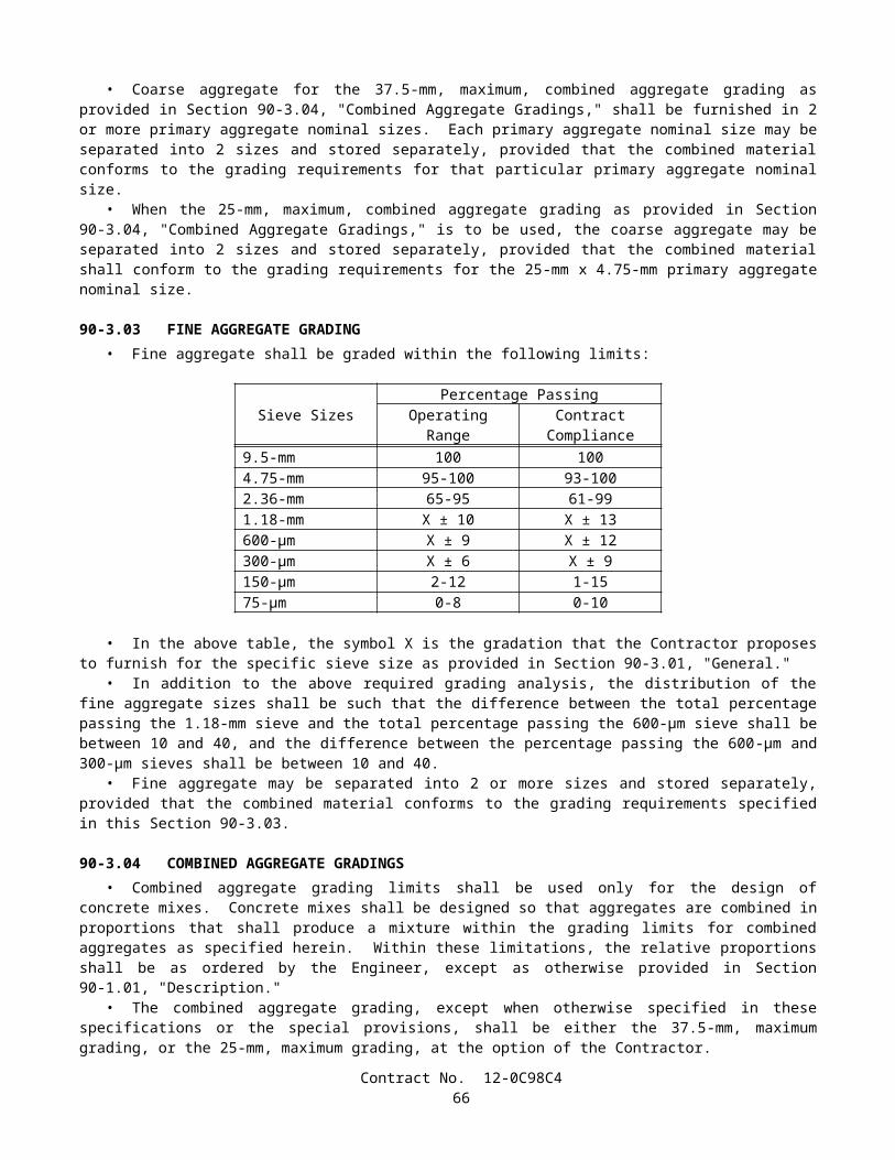
5. Excavations in side slopes, where the slope is steeper than 1:4 (vertical:horizontal).6. Excavations protected by existing barrier or railing.
B. Temporarily Unprotected Permanent Obstacles.—The work includes the installation of a fixed obstacle together with a protective system, such as a sign structure together with protective railing, and the Contractor elects to install the obstacle prior to installing the protective system; or the Contractor, for the Contractor's convenience and with permission of the Engineer, removes a portion of an existing protective railing at an obstacle and does not replace such railing complete in place during the same day.
C. Storage Areas.—Material or equipment is stored within 3.6 m of the lane and the storage is not otherwise prohibited by the provisions of the Standard Specifications and these special provisions.
The approach end of temporary railing (Type K), installed in conformance with the provisions in this section "Public Safety" and in Section 7-1.09, "Public Safety," of the Standard Specifications, shall be offset a minimum of 4.6 m from the edge of the traffic lane open to public traffic. The temporary railing shall be installed on a skew toward the edge of the traffic lane of not more than 0.3-m transversely to 3 m longitudinally with respect to the edge of the traffic lane. If the 4.6 -m minimum offset cannot be achieved, the temporary railing shall be installed on the 10 to 1 skew to obtain the maximum available offset between the approach end of the railing and the edge of the traffic lane, and an array of temporary crash cushion modules shall be installed at the approach end of the temporary railing.
Temporary railing (Type K) shall conform to the provisions in Section 12-3.08, "Temporary Railing (Type K)," of the Standard Specifications. Temporary railing (Type K), conforming to the details shown on 1999 Standard Plan T3, may be used. Temporary railing (Type K) fabricated prior to January 1, 1993, and conforming to 1988 Standard Plan B11-30 may be used, provided the fabrication date is printed on the required Certificate of Compliance.
Temporary crash cushion modules shall conform to the provisions in "Temporary Crash Cushion Module" of these special provisions.
Except for installing, maintaining and removing traffic control devices, whenever work is performed or equipment is operated in the following work areas, the Contractor shall close the adjacent traffic lane unless otherwise provided in the Standard Specifications and these special provisions:
Approach Speed of Public Traffic (Posted Limit) (Kilometers Per Hour)
Work Areas
Over 72 (45 Miles Per Hour) Within 1.8 m of a traffic lane but not on a traffic lane56 to 72 (35 to 45 Miles Per Hour) Within 0.9-m of a traffic lane but not on a traffic lane
The lane closure provisions of this section shall not apply if the work area is protected by permanent or temporary railing or barrier.
When traffic cones or delineators are used to delineate a temporary edge of a traffic lane, the line of cones or delineators shall be considered to be the edge of the traffic lane, however, the Contractor shall not reduce the width of an existing lane to less than 3 m without written approval from the Engineer.
When work is not in progress on a trench or other excavation that required closure of an adjacent lane, the traffic cones or portable delineators used for the lane closure shall be placed off of and adjacent to the edge of the traveled way. The spacing of the cones or delineators shall be not more than the spacing used for the lane closure.
Suspended loads or equipment shall not be moved nor positioned over public traffic or pedestrians.Full compensation for conforming to the provisions in this section "Public Safety," including furnishing and installing
temporary railing (Type K) and temporary crash cushion modules, shall be considered as included in the contract prices paid for the various items of work involved and no additional compensation will be allowed therefor.
5-1.05 TESTINGTesting of materials and work shall conform to the provisions in Section 6-3, "Testing," of the Standard Specifications
and these special provisions.Whenever the provisions of Section 6-3.01, "General," of the Standard Specifications refer to tests or testing, it shall
mean tests to assure the quality and to determine the acceptability of the materials and work.The Engineer will deduct the costs for testing of materials and work found to be unacceptable, as determined by the tests
performed by the Department, and the costs for testing of material sources identified by the Contractor which are not used for the work, from moneys due or to become due to the Contractor. The amount deducted will be determined by the Engineer.
Contract No. 12-0C98C468

5-1.06 REMOVAL OF ASBESTOS AND HAZARDOUS SUBSTANCESWhen the presence of asbestos or hazardous substances are not shown on the plans or indicated in the specifications and
the Contractor encounters materials which the Contractor reasonably believes to be asbestos or a hazardous substance as defined in Section 25914.1 of the Health and Safety Code, and the asbestos or hazardous substance has not been rendered harmless, the Contractor may continue work in unaffected areas reasonably believed to be safe. The Contractor shall immediately cease work in the affected area and report the condition to the Engineer in writing.
In conformance with Section 25914.1 of the Health and Safety Code, removal of asbestos or hazardous substances including exploratory work to identify and determine the extent of the asbestos or hazardous substance will be performed by separate contract.
If delay of work in the area delays the current controlling operation, the delay will be considered a right of way delay and the Contractor will be compensated for the delay in conformance with the provisions in Section 8-1.09, "Right of Way Delays," of the Standard Specifications.
Contract No. 12-0C98C469

5-1.07 YEAR 2000 COMPLIANCEThis contract is subject to Year 2000 Compliance for automated devices in the State of California.Year 2000 compliance for automated devices in the State of California is achieved when embedded functions have or
create no logical or mathematical inconsistencies when dealing with dates prior to and beyond 1999. The year 2000 is recognized and processed as a leap year. The product shall operate accurately in the manner in which the product was intended for date operation without requiring manual intervention.
The Contractor shall provide the Engineer a Certificate of Compliance from the manufacturer in conformance with the provisions in Section 6-1.07, "Certificates of Compliance," of the Standard Specifications for all automated devices furnished for the project.
5-1.08 SUBCONTRACTOR AND DVBE RECORDSThe Contractor shall maintain records of all subcontracts entered into with certified DVBE subcontractors and records of
materials purchased from certified DVBE suppliers. The records shall show the name and business address of each DVBE subcontractor or vendor and the total dollar amount actually paid each DVBE subcontractor or vendor.
Upon completion of the contract, a summary of these records shall be prepared on Form CEM-2402 (S) and certified correct by the Contractor or the Contractor's authorized representative, and shall be furnished to the Engineer.
5-1.086 PERFORMANCE OF DVBE SUBCONTRACTORS AND SUPPLIERSThe DVBEs listed by the Contractor in response to the provisions in Section 2-1.04, "Submission of DVBE
Information," and Section 3, "Award and Execution of Contract," of these special provisions, which are determined by the Department to be certified DVBEs, shall perform the work and supply the materials for which they are listed, unless the Contractor has received prior written authorization to perform the work with other forces or to obtain the materials from other sources.
Authorization to utilize other forces or sources of materials may be requested for the following reasons:
A. The listed DVBE, after having had a reasonable opportunity to do so, fails or refuses to execute a written contract, when the written contract, based upon the general terms, conditions, plans and specifications for the project, or on the terms of the subcontractor's or supplier's written bid, is presented by the Contractor.
B. The listed DVBE becomes bankrupt or insolvent.C. The listed DVBE fails or refuses to perform the subcontract or furnish the listed materials.D. The Contractor stipulated that a bond was a condition of executing a subcontract and the listed DVBE subcontractor
fails or refuses to meet the bond requirements of the Contractor.E. The work performed by the listed subcontractor is substantially unsatisfactory and is not in substantial conformance
with the plans and specifications or the subcontractor is substantially delaying or disrupting the progress of the work.
F. The listed DVBE subcontractor is not licensed pursuant to the Contractor's License Law.G. It would be in the best interest of the State.
The Contractor shall not be entitled to payment for the work or material unless it is performed or supplied by the listed DVBE or by other forces (including those of the Contractor) pursuant to prior written authorization of the Engineer.
5-1.09 SUBCONTRACTINGAttention is directed to the provisions in Section 8-1.01, "Subcontracting," of the Standard Specifications, Section 2,
"Proposal Requirements and Conditions," Section 2-1.04, "Submission of DVBE Information," and Section 3, "Award and Execution of Contract," of these special provisions and these special provisions.
Pursuant to the provisions in Section 1777.1 of the Labor Code, the Labor Commissioner publishes and distributes a list of contractors ineligible to perform work as a subcontractor on a public works project. This list of debarred contractors is available from the Department of Industrial Relations web site at:
http://www.dir.ca.gov/DLSE/Debar.html.
The DVBE information furnished under Section 2-1.04, "Submission of DVBE Information," of these special provisions is in addition to the subcontractor information required to be furnished in Section 8-1.01, "Subcontracting," and Section 2-1.054, "Required Listing of Proposed Subcontractors," of the Standard Specifications.
Contract No. 12-0C98C470

Section 10115 of the Public Contract Code requires the Department to implement provisions to establish a goal for Disabled Veteran Business Enterprise (DVBE) participation in highway contracts that are State funded. As a part of this requirement:
A. No substitution of a DVBE subcontractor shall be made at any time without the written consent of the Department, and
B. If a DVBE subcontractor is unable to perform successfully and is to be replaced, the Contractor shall make good faith efforts to replace the original DVBE subcontractor with another DVBE subcontractor.
The provisions in Section 2-1.02, "Disabled Veteran Business Enterprise (DVBE)," of these special provisions that DVBEs shall be certified on the date bids are opened does not apply to DVBE substitutions after award of the contract.
5-1.10 PROMPT PROGRESS PAYMENT TO SUBCONTRACTORSAttention is directed to the provisions in Sections 10262 and 10262.5 of the Public Contract Code concerning prompt
payment to subcontractors.
5-1.103 RECORDSThe Contractor shall maintain cost accounting records for the contract pertaining to, and in such a manner as to provide a
clear distinction between, the following six categories of costs of work during the life of the contract:
A. Direct costs of contract item work.B. Direct costs of changes in character in conformance with Section 4-1.03C, "Changes in Character of Work," of the
Standard Specifications.C. Direct costs of extra work in conformance with Section 4-1.03D, "Extra Work," of the Standard Specifications.D. Direct costs of work not required by the contract and performed for others.E. Direct costs of work performed under a notice of potential claim in conformance with the provisions in Section
9-1.04, "Notice of Potential Claim," of the Standard Specifications.F. Indirect costs of overhead.
Cost accounting records shall include the information specified for daily extra work reports in Section 9-1.03C, "Records," of the Standard Specifications. The requirements for furnishing the Engineer completed daily extra work reports shall only apply to work paid for on a force account basis.
The cost accounting records for the contract shall be maintained separately from other contracts, during the life of the contract, and for a period of not less than 3 years after the date of acceptance of the contract. If the Contractor intends to file claims against the Department, the Contractor shall keep the cost accounting records specified above until complete resolution of all claims has been reached.
5-1.11 PROTECTED NESTING BIRDSBetween February 1 and September 1, the Contractor shall notify the Engineer 15 working days prior to beginning work
disturbing structures, the ground or vegetation on Route 73 from Station 1148+50 to Station 1149+50 as shown on the plans. The Contractor shall not commence such construction activities, during this time period, until notified in writing by the Engineer that said construction activities can proceed.
If evidence of bird nesting is discovered, the Contractor shall not disturb the nesting birds or nests and shall immediately stop work within a 153 meter radius of the nest and notify the Engineer. The Contractor shall not re-commence construction activities until notified in writing by the Engineer.
The Contractor shall remove equipment from the project location where protected nesting birds have been located as directed by the Engineer.
The Contractor shall use exclusion techniques for bird nesting areas as directed by the Engineer to prevent protected nesting birds from nesting on the ground, on structures, in trees, in shrubs, or other vegetation within the project limits.
Preventing nesting by using appropriate exclusion techniques as approved by the Engineer will be paid for as extra work as provided in Section 4-1.03D, "Extra Work," of the Standard Specifications.
Nothing in this section shall relieve the Contractor from providing for public safety in conformance with the provisions in Section 7-1.09, "Public Safety," of the Standard Specifications.
5-1.12 AREAS FOR CONTRACTOR'S USEAttention is directed to the provisions in Section 7-1.19, "Rights in Land and Improvements," of the Standard
Specifications and these special provisions.
Contract No. 12-0C98C471

Areas available for the exclusive use of the Contractor are designated by the Engineer. Use of the Contractor's work areas and other State-owned property shall be at the Contractor's own risk, and the State shall not be held liable for damage to or loss of materials or equipment located within these areas.
The Contractor shall obtain encroachment permits prior to occupying State-owned parcels outside the contract limits. The required encroachment permits may be obtained from the Department of Transportation, Permit Engineer, District 12, Construction Office, 3337 Michelson Drive, Suite 100, Irvine, California, First floor.
Residence trailers will not be allowed within the highway right of way, except that one trailer will be allowed for yard security purposes.
The Contractor shall remove equipment, materials, and rubbish from the work areas and other State-owned property which the Contractor occupies. The Contractor shall leave the areas in a presentable condition in conformance with the provisions in Section 4-1.02, "Final Cleaning Up," of the Standard Specifications.
The Contractor shall secure, at the Contractor's own expense, areas required for plant sites, storage of equipment or materials or for other purposes, if sufficient area is not available to the Contractor within the contract limits, or at the sites designated on the plans outside the contract limits.
5-1.13 PAYMENTSAttention is directed to Sections 9-1.06, "Partial Payments," and 9-1.07, "Payment After Acceptance," of the Standard
Specifications and these special provisions.For the purpose of making partial payments pursuant to Section 9-1.06, "Partial Payments," of the Standard
Specifications, the amount set forth for the contract items of work hereinafter listed shall be deemed to be the maximum value of the contract item of work which will be recognized for progress payment purposes:
A. Clearing and Grubbing $3,380.00
After acceptance of the contract pursuant to the provisions in Section 7-1.17, "Acceptance of Contract," of the Standard Specifications, the amount, if any, payable for a contract item of work in excess of the maximum value for progress payment purposes hereinabove listed for the item, will be included for payment in the first estimate made after acceptance of the contract.
In determining the partial payments to be made to the Contractor, only the following listed materials will be considered for inclusion in the payment as materials furnished but not incorporated in the work:
A. Miscellaneous Iron and SteelB. Chain Link Fence (Type CL-1.8)C. 1.5 M Chain Link Gate (Type CL-1.8)
5-1.14 SOUND CONTROL REQUIREMENTSSound control shall conform to the provisions in Section 7-1.01I, "Sound Control Requirements," of the Standard
Specifications and these special provisions.The noise level from the Contractor's operations, between the hours of 9:00 p.m. and 6:00 a.m., shall not exceed 86 db at
a distance of 15 m. This requirement shall not relieve the Contractor from responsibility for complying with local ordinances regulating noise level.
The noise level requirement shall apply to the equipment on the job or related to the job, including but not limited to trucks, transit mixers or transient equipment that may or may not be owned by the Contractor. The use of loud sound signals shall be avoided in favor of light warnings except those required by safety laws for the protection of personnel.
Full compensation for conforming to the requirements of this section shall be considered as included in the prices paid for the various contract items of work involved and no additional compensation will be allowed therefore.
5-1.15 CULTURAL RESOURCESThe California Public Resources Code Chapter 1.7, Section 5097.5 makes it a misdemeanor for anyone to knowingly
disturb an archaeological or historical feature. California Public Resources Code Sections 5097.98 and 5097.99 require protection of Native American remains which may be found and outlines procedures for handling any burials found.
The California Administrative Code, Title 14, Section 4308, requires that no person disfigure any object of historical interest or value. The California Penal Code, Title 14, Part 1, Section 622-1/2 makes it a misdemeanor to destroy anything of historical value within any public place.
Should human skeletal material or archaeological remains be found during construction activities, all work must be halted within twenty meters of the find. The Contractor shall notify the Engineer immediately. Construction activities within twenty meters of the find shall remain halted until the Contractor has been notified that construction in the vicinity of the find
Contract No. 12-0C98C472

may resume. If, in the opinion of the Engineer, the Contractor's operations are delayed or interfered with due to investigations made of the archaeological find, the State will compensate the Contractor for such delays to the extent provided in Section 8-1.09, "Right of Way Delays," of the Standard Specifications.
The Department reserves the right to use other forces for exploratory work to identify and determine the extent of the area requiring archaeological artifact recovery and for removing archaeological artifacts from such area
Full compensation for conforming to the above requirements shall be considered as included in the contract prices paid for the various contract items of work involved and no additional compensation will be allowed therefore.
5-1.16 RELATIONS WITH CALIFORNIA REGIONAL WATER QUALITY CONTROL BOARDThe location of the construction is within an area controlled by the Santa Ana Regional Water Quality Control Board.
Regional Water Quality Control Board Order No. 98-67, NPDES, No. CAG998001 has been issued covering work to be performed under this contract. The Contractor shall be fully informed of rules, regulations, and conditions that may govern the Contractor's operations in the areas and shall conduct the work accordingly.
Copies of the order may be obtained at the Department of Transportation, Plans and Bid Documents Section, MS 26, 1120 N Street, Room 200, Sacramento, CA 95814, Telephone 916-654-4490, and are available for inspection at the office of the District Director of Transportation at District 12, Construction Office, 3337 Michelson Drive, Suite 100, Irvine, California.
Attention is directed to Section 7-1.11, "Preservation of Property," and Section 7-1.12, "Indemnification and Insurance," of the Standard Specifications.
The Contractor's attention is directed to the following conditions which are among those established by the Regional Water Quality Control Board in their Order for this project:
A. If groundwater is encountered during construction, all dewatering activities are regulated under a regional NPDES dewatering/DE MINIMUS permit (Order No. 98-67, NPDES, No. CAG998001) issued to Caltrans by the Santa Ana Regional Water Quality Board.
Changes in the above listed conditions proposed by the Contractor shall be submitted to the Engineer for transmittal to the Regional Water Quality Control Board for their approval. Changes shall not be implemented until approved in writing by the Regional Water Quality Control Board.
Attention is directed to Section 8-1.06, "Time of Completion," of the Standard Specifications. Days during which the Contractor's operations are restricted in the floodway by the requirements of this section shall be considered to be nonworking days if these restrictions cause a delay in the current controlling operation or operations.
The Contractor shall notify the Caltrans District 12 Storm Water Unit at (949) 724-2189 prior to discharging any groundwater to storm drains or surface waters.
5-1.17 ENVIRONMENTALLY SENSITIVE AREAAttention is directed to the designated Environmentally Sensitive Areas (ESAs) shown on the plans. The exact location
of the boundaries of ESAs will be determined by the Engineer and shall be clearly delineated by the placement of temporary fence (Type ESA) as specified in these special provisions.
The Contractor’s attention is directed to the areas designated on the plans as "Environmentally Sensitive Area" (Coastal Sage Mitigation Area), and to certain State and Federal regulations, which may pertain to such areas. These areas shall be completely avoided by all parties involved in any work activity in connection with the performance of this contract.
The Contractor shall take precautionary measures, including giving written notice to employees and subcontractors, to insure that forces, employees or subcontractors do not enter areas designated as Environmentally Sensitive Areas.
The removal of the coastal sage scrub vegetation within the temporary impact area of the ESA as shown on the plans shall be removed between September 1 to February 15.
Entry into ESA areas will be allowed to install, maintain and remove Temporary Fence (Type ESA). The Contractor shall notify the Engineer before entering ESA areas for above-mentioned work. No entry shall be made into ESA areas for the above-mentioned work without a State Biologist present.
Vehicle access, storage or transport of materials or equipment, or other project related activities are prohibited within the boundaries of ESAs. Vehicular traffic shall not be used in ESA areas during fencing operations.
The Contractor shall repair, or perform work to mitigate, damage or impacts to ESAs caused by the Contractor's operations, at the Contractor's expense. If the Engineer determines repairs or mitigation work will be performed by others, or if mitigation fees are assessed the Department, deductions from moneys due or to become due the Contractor will be made for the repair or mitigation costs.
Contract No. 12-0C98C473

SECTION 6. (BLANK)
SECTION 7. (BLANK)
SECTION 8. MATERIALS
SECTION 8-1. MISCELLANEOUS
8-1.01 SUBSTITUTION OF NON-METRIC MATERIALS AND PRODUCTSOnly materials and products conforming to the requirements of the specifications shall be incorporated in the work.
When metric materials and products are not available, and when approved by the Engineer, and at no cost to the State, materials and products in the United States Standard Measures which are of equal quality and of the required properties and characteristics for the purpose intended, may be substituted for the equivalent metric materials and products, subject to the following provisions:
A. Materials and products shown on the plans or in the special provisions as being equivalent may be substituted for the metric materials and products specified or detailed on the plans.
B. Before other non-metric materials and products will be considered for use, the Contractor shall furnish, at the Contractor's expense, evidence satisfactory to the Engineer that the materials and products proposed for use are equal to or better than the materials and products specified or detailed on the plans. The burden of proof as to the quality and suitability of substitutions shall be upon the Contractor and the Contractor shall furnish necessary information as required by the Engineer. The Engineer will be the sole judge as to the quality and suitability of the substituted materials and products and the Engineer's decision will be final.
C. When the Contractor elects to substitute non-metric materials and products, including materials and products shown on the plans or in the special provisions as being equivalent, the list of sources of material specified in Section 6-1.01, "Source of Supply and Quality of Materials," of the Standard Specification shall include a list of substitutions to be made and contract items involved. In addition, for a change in design or details, the Contractor shall submit plans and working drawings in conformance with the provisions in Section 5-1.02, "Plans and Working Drawings," of the Standard Specifications. The plans and working drawings shall be submitted at least 7 days before the Contractor intends to begin the work involved.
Unless otherwise specified, the following substitutions of materials and products will be allowed:
SUBSTITUTION TABLE FOR SIZES OF HIGH STRENGTH STEEL FASTENERS ASTM Designation: A 325M
METRIC SIZE SHOWN ON THE PLANSmm x thread pitch
SIZE TO BE SUBSTITUTED inch
M16 x 2 5/8M20 x 2.5 3/4M22 x 2.5 7/8M24 x 3 1M27 x 3 1-1/8
M30 x 3.5 1-1/4M36 x 4 1-1/2
Contract No. 12-0C98C474

SUBSTITUTION TABLE FOR PLAIN WIRE REINFORCEMENTASTM Designation: A 82
METRIC SIZE SHOWN ON THE PLANSmm2
SIZE TO BE SUBSTITUTEDInch2 x 100
MW9 W1.4MW10 W1.6MW13 W2.0MW15 W2.3MW19 W2.9MW20 W3.1MW22 W3.5MW25 W3.9, except W3.5 in piles onlyMW26 W4.0MW30 W4.7MW32 W5.0MW35 W5.4MW40 W6.2MW45 W6.5MW50 W7.8MW55 W8.5, except W8.0 in piles onlyMW60 W9.3MW70 W10.9, except W11.0 in piles onlyMW80 W12.4MW90 W14.0MW100 W15.5
SUBSTITUTION TABLE FOR BAR REINFORCEMENTMETRIC BAR DESIGNATION
NUMBER1 SHOWN ON THE PLANSBAR DESIGNATION
NUMBER2 TO BE SUBSTITUTED10 313 416 519 622 725 829 932 1036 1143 1457 18
1Bar designation numbers approximate the number of millimeters of the nominal diameter of the bars.2Bar numbers are based on the number of eighths of an inch included in the nominal diameter of the bars.No adjustment will be required in spacing or total number of reinforcing bars due to a difference in minimum yield strength between metric and non-metric bars.
Contract No. 12-0C98C475
SUBSTITUTION TABLE FOR SIZES OF:(1) STEEL FASTENERS FOR GENERAL APPLICATIONS (ASTM Designation: A 307 or AASHTO Designation: M 314, Grade 36 or 55), and (2) HIGH STRENGTH STEEL FASTENERS (ASTM Designation: A 325 or A 449)
METRIC SIZE SHOWN ON THE PLANSMm
SIZE TO BE SUBSTITUTEDinch
6 or 6.35 1/48 or 7.94 5/1610 or 9.52 3/811 or 11.11 7/1613 or 12.70 1/214 or 14.29 9/1616 or 15.88 5/819 or 19.05 3/422 or 22.22 7/8
24, 25, or 25.40 129 or 28.58 1-1/832 or 31.75 1-1/435 or 34.93 1-3/838 or 38.10 1-1/244 or 44.45 1-3/451 or 50.80 257 or 57.15 2-1/464 or 63.50 2-1/270 or 69.85 2-3/476 or 76.20 383 or 82.55 3-1/489 or 88.90 3-1/295 or 95.25 3-3/4
102 or 101.60 4
Contract No. 12-0C98C476
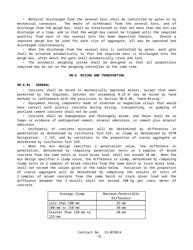
SUBSTITUTION TABLE FOR NOMINAL THICKNESS OF SHEET METALUNCOATED HOT AND COLD ROLLED SHEETS HOT-DIPPED ZINC COATED SHEETS
(GALVANIZED)METRIC THICKNESS
SHOWN ON THE PLANSmm
GAGE TO BE SUBSTITUTED
inch
METRIC THICKNESSSHOWN ON THE PLANS
Mm
GAGE TO BE SUBSTITUTED
inch7.94 0.3125 4.270 0.16816.07 0.2391 3.891 0.15325.69 0.2242 3.510 0.13825.31 0.2092 3.132 0.12334.94 0.1943 2.753 0.10844.55 0.1793 2.372 0.09344.18 0.1644 1.994 0.07853.80 0.1495 1.803 0.07103.42 0.1345 1.613 0.06353.04 0.1196 1.461 0.05752.66 0.1046 1.311 0.05162.28 0.0897 1.158 0.04561.90 0.0747 1.006 or 1.016 0.03961.71 0.0673 0.930 0.03661.52 0.0598 0.853 0.03361.37 0.0538 0.777 0.03061.21 0.0478 0.701 0.02761.06 0.0418 0.627 0.02470.91 0.0359 0.551 0.02170.84 0.0329 0.513 0.02020.76 0.0299 0.475 0.01870.68 0.0269 -------- --------0.61 0.0239 -------- --------0.53 0.0209 -------- --------0.45 0.0179 -------- --------0.42 0.0164 -------- --------0.38 0.0149 -------- --------
Contract No. 12-0C98C477
SUBSTITUTION TABLE FOR WIREMETRIC THICKNESS
SHOWN ON THE PLANSMm
WIRE THICKNESSTO BE SUBSTITUTED
InchGAGE NO.
6.20 0.244 35.72 0.225 45.26 0.207 54.88 0.192 64.50 0.177 74.11 0.162 83.76 0.148 93.43 0.135 103.05 0.120 112.69 0.106 122.34 0.092 132.03 0.080 141.83 0.072 151.57 0.062 161.37 0.054 171.22 0.048 181.04 0.041 190.89 0.035 20
SUBSTITUTION TABLE FOR PIPE PILESMETRIC SIZE
SHOWN ON THE PLANSMm x mm
SIZETO BE SUBSTITUTED
inch x inchPP 360 x 4.55 NPS 14 x 0.179PP 360 x 6.35 NPS 14 x 0.250PP 360 x 9.53 NPS 14 x 0.375PP 360 x 11.12 NPS 14 x 0.438PP 406 x 12.70 NPS 16 x 0.500
PP 460 x T NPS 18 x T"PP 508 x T NPS 20 x T"PP 559 x T NPS 22 x T"PP 610 x T NPS 24 x T"PP 660 x T NPS 26 x T"PP 711 x T NPS 28 x T"PP 762 x T NPS 30 x T"PP 813 x T NPS 32 x T"PP 864 x T NPS 34 x T"PP 914 x T NPS 36 x T"PP 965 x T NPS 38 x T"PP 1016 x T NPS 40 x T"PP 1067 x T NPS 42 x T"PP 1118 x T NPS 44 x T"PP 1219 x T NPS 48 x T"PP 1524 x T NPS 60 x T"
The thickness in millimeters (T) represents an exact conversion of the thickness in inches (T").
Contract No. 12-0C98C478

SUBSTITUTION TABLE FOR STRUCTURAL TIMBER AND LUMBER METRIC MINIMUM
DRESSED DRY,SHOWN ON THE PLANS
mm x mm
METRIC MINIMUM DRESSED GREEN,
SHOWN ON THE PLANSmm x mm
NOMINAL SIZE
TO BE SUBSTITUTEDinch x inch
19x89 20x90 1x438x89 40x90 2x464x89 65x90 3x489x89 90x90 4x4
140x140 143x143 6x6140x184 143x190 6x8184x184 190x190 8x8235x235 241x241 10x10286x286 292x292 12x12
SUBSTITUTION TABLE FOR NAILS AND SPIKESMETRIC COMMON NAIL,SHOWN ON THE PLANS
Length, mmDiameter, mm
METRIC BOX NAIL,SHOWN ON THE PLANS
Length, mmDiameter, mm
METRIC SPIKE,SHOWN ON THE
PLANSLength, mm
Diameter, mm
SIZETO BE
SUBSTITUTEDPenny-weight
50.802.87
50.802.51
______ 6d
63.503.33
63.502.87
______ 8d
76.203.76
76.203.25
76.204.88
10d
82.553.76
82.553.25
82.554.88
12d
88.904.11
88.903.43
88.905.26
16d
101.604.88
101.603.76
101.605.72
20d
114.305.26
114.303.76
114.306.20
30d
127.005.72
127.004.11
127.006.68
40d
______ ______ 139.707.19
50d
______ ______ 152.407.19
60d
Contract No. 12-0C98C479

SUBSTITUTION TABLE FOR IRRIGATION COMPONENTS
METRICWATER METERS, TRUCK LOADING STANDPIPES, VALVES, BACKFLOW PREVENTERS, FLOW
SENSORS, WYE STRAINERS, FILTER
ASSEMBLY UNITS, PIPE SUPPLY LINES, AND PIPE
IRRIGATION SUPPLY LINES
SHOWN ON THE PLANSDIAMETER NOMINAL
(DN) mm
NOMINAL SIZE
TO BE SUBSTITUTED
Inch15 ½20 ¾25 132 1-1/440 1-1/250 265 2-1/275 3100 4150 6200 8250 10300 12350 14400 16
Unless otherwise specified, substitutions of United States Standard Measures standard structural shapes corresponding to the metric designations shown on the plans and in conformance with the requirements in ASTM Designation: A 6/A 6M, Annex 2, will be allowed.
8-1.02 PREQUALIFIED AND TESTED SIGNING AND DELINEATION MATERIALSThe Department maintains the following list of Prequalified and Tested Signing and Delineation Materials. The
Engineer shall not be precluded from sampling and testing products on the list of Prequalified and Tested Signing and Delineation Materials.
The manufacturer of products on the list of Prequalified and Tested Signing and Delineation Materials shall furnish the Engineer a Certificate of Compliance in conformance with the provisions in Section 6-1.07, "Certificates of Compliance," of the Standard Specifications for each type of traffic product supplied.
For those categories of materials included on the list of Prequalified and Tested Signing and Delineation Materials, only those products shown within the listing may be used in the work. Other categories of products, not included on the list of Prequalified and Tested Signing and Delineation Materials, may be used in the work provided they conform to the requirements of the Standard Specifications.
Materials and products may be added to the list of Prequalified and Tested Signing and Delineation Materials if the manufacturer submits a New Product Information Form to the New Product Coordinator at the Transportation Laboratory. Upon a Departmental request for samples, sufficient samples shall be submitted to permit performance of required tests. Approval of materials or products will depend upon compliance with the specifications and tests the Department may elect to perform.
Contract No. 12-0C98C480
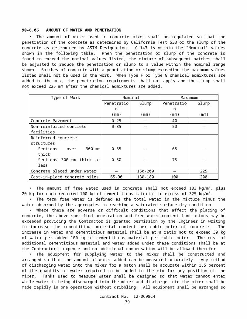
PAVEMENT MARKERS, PERMANENT TYPERetroreflective With Abrasion Resistant Surface (ARS)
A. Apex, Model 921AR (100 mm x 100 mm)B. Avery Dennison (formerly Stimsonite), Models C88 (100 mm x 100 mm), 911 (100 mm x 100 mm) and 953
(70 mm x 114 mm)C. Ray-O-Lite, Model "AA" ARS (100 mm x 100 mm)D. 3M Series 290 (89 mm x 100 mm)E. 3M Series 290 PSA, with pressure sensitive adhesive pad (89 mm x 100 mm)
Retroreflective With Abrasion Resistant Surface (ARS)(for recessed applications only)
A. Avery Dennison (formerly Stimsonite), Model 948 (58 mm x 119 mm)B. Avery Dennison (formerly Stimsonite), Model 944SB (51 mm x 100 mm)*C. Ray-O-Lite, Model 2002 (58 mm x 117 mm)D. Ray-O-Lite, Model 2004 ARS (51 mm x 100 mm)*
*For use only in 114 mm wide (older) recessed slots
Non-Reflective, 100 mm RoundA. Alpine Products, "D-Dot" and "ANR" (ABS)B. Apex Universal (Ceramic)C. Apex Universal, Models 929 (ABS) and 929PP (Polypropylene)D. Elgin Molded Plastics, "Empco-Lite" Model 900 (ABS)E. Glowlite (Ceramic)F. Hi-Way Safety, Inc., Models P20-2000W and 2001Y (ABS)G. Interstate Sales, "Diamond Back" (ABS) and (Polypropylene)H. Novabrite Models Cdot (White) Cdot-y (Yellow), CeramicI. Novabrite Models Adot-w (White) Adot-y (Yellow), (ABS)J. Novabrite Models Pdot-w (White) Pdot-y (Yellow), PolypropyleneK. Road Creations, Model RCB4NR (Acrylic)L. Three D Traffic Works TD10000 (ABS), TD10500 (Polypropylene)M. Zumar Industries, "Titan TM40A" (ABS)
PAVEMENT MARKERS, TEMPORARY TYPETemporary Markers For Long Term Day/Night Use (6 months or less)
A. Apex Universal, Model 924 (100 mm x 100 mm)B. Elgin Molded Plastics, "Empco-Lite" Model 901 (100 mm x 100 mm)C. Road Creations, Model R41C (100 mm x 100 mm)D. Vega Molded Products "Temporary Road Marker" (75 mm x 100 mm)
Temporary Markers For Short Term Day/Night Use (14 days or less)(For seal coat or chip seal applications, clear protective covers are required)
A. Apex Universal, Model 932B. Bunzl Extrusion, Models T.O.M., T.R.P.M., and "HH" (High Heat)C. Hi-Way Safety, Inc., Model 1280/1281
STRIPING AND PAVEMENT MARKING MATERIALPermanent Traffic Striping and Pavement Marking Tape
A. Advanced Traffic Marking, Series 300 and 400B. Brite-Line, Series 1000C. Brite-Line, "DeltaLine XRP"D. Swarco Industries, "Director 35" (For transverse application only)E. Swarco Industries, "Director 60"F. 3M, "Stamark" Series 380 and 5730G. 3M, "Stamark" Series 420 (For transverse application only)
Contract No. 12-0C98C481

Temporary (Removable) Striping and Pavement Marking Tape (6 months or less)A. Advanced Traffic Marking, Series 200B. Brite-Line, Series 100C. Garlock Rubber Technologies, Series 2000D. P.B. Laminations, Aztec, Grade 102E. Swarco Industries, "Director-2"F. Trelleborg Industri, R140 SeriesG. 3M, Series 620 "CR", and Series A750H. 3M, Series A145, Removable Black Line Mask
(Black Tape: for use only on Asphalt Concrete Surfaces)I. Advanced Traffic Marking Black "Hide-A-Line"
(Black Tape: for use only on Asphalt Concrete Surfaces)J. Brite-Line "BTR" Black Removable Tape
(Black Tape: for use only on Asphalt Concrete Surfaces)K. Trelleborg Industri, RB-140
(Black Tape: for use only on Asphalt Concrete Surfaces)
Preformed Thermoplastic (Heated in place)A. Avery Dennison, "Hotape"B. Flint Trading, "Premark," "Premark 20/20 Flex," and "Premark 20/20 Flex Plus"
Ceramic Surfacing Laminate, 150 mm x 150 mmA. Safeline Industries/Highway Ceramics, Inc.
CLASS 1 DELINEATORSOne Piece Driveable Flexible Type, 1700 mm
A. Bunzl Extrusion, "Flexi-Guide Models 400 and 566"B. Carsonite, Curve-Flex CFRM-400C. Carsonite, Roadmarker CRM-375D. FlexStake, Model 654 TME. GreenLine Models HWD1-66 and CGD1-66F. J. Miller Industries, Model JMI-375 (with soil anchor)
Special Use Type, 1700 mmA. Bunzl Extrusion, Model FG 560 (with 450 mm U-Channel base)B. Carsonite, "Survivor" (with 450 mm U-Channel base)C. Carsonite, Roadmarker CRM-375 (with 450 mm U-Channel base)D. FlexStake, Model 604E. GreenLine Models HWDU and CGD (with 450 mm U-Channel base)F. Impact Recovery Model D36, with #105 Driveable BaseG. Safe-Hit with 200 mm pavement anchor (SH248-GP1)H. Safe-Hit with 380 mm soil anchor (SH248-GP2) and with 450 mm soil anchor (SH248-GP3)
Surface Mount Type, 1200 mmA. Bent Manufacturing Company, Masterflex Model MF-180EX-48B. Carsonite, "Super Duck II"C. FlexStake, Surface Mount, Models 704 and 754 TMD. Impact Recovery Model D48, with #101 Fixed (Surface-Mount) BaseE. Three D Traffic Works "Channelflex" ID No. 522248W
CHANNELIZERSSurface Mount Type, 900 mm
A. Bent Manufacturing Company, Masterflex Models MF-360-36 (Round) and MF-180-36 (Flat)B. Bunzl Extrusion, Flexi-Guide Models FG300LD and FG300URC. Carsonite, "Super Duck" (Flat SDF-436, Round SDR-336)D. Carsonite, "Super Duck II" Model SDCF203601MB "The Channelizer"
Contract No. 12-0C98C482
E. FlexStake, Surface Mount, Models 703 and 753 TMF. GreenLine, Model SMD-36G. Hi-Way Safety, Inc. "Channel Guide Channelizer" Model CGC36H. Impact Recovery Model D36, with #101 Fixed (Surface-Mount) BaseI. Repo, Models 300 and 400J. Safe-Hit, Guide Post, Model SH236SMAK. The Line Connection, "Dura-Post" Model DP36-3 (Permanent)L. The Line Connection, "Dura-Post" Model DP36-3C (Temporary)M. Three D Traffic Works "Channelflex" ID No. 522053W
Lane Separation SystemA. Bunzl "Flexi-Guide (FG) 300 Curb System"B. Qwick Kurb, "Klemmfix Guide System"C. Recycled Technology, Inc. "Safe-Lane System"
CONICAL DELINEATORS, 1070 mm(For 700 mm Traffic Cones, see Standard Specifications)A. Bent Manufacturing Company "T-Top"B. Plastic Safety Systems "Navigator-42"C. Radiator Specialty Company "Enforcer"D. Roadmaker Company "Stacker"E. TrafFix Devices "Grabber"F. Three D Traffic Works "Ringtop" TD7000, ID No. 742143
OBJECT MARKERSType "K", 450 mm
A. Bunzl, Model FG318PEB. Carsonite, Model SMD 615C. FlexStake, Model 701 KMD. Repo, Models 300 and 400E. Safe-Hit, Model SH718SMAF. The Line Connection, Model DP21-4K
Type "K-4" / "Q" Object Markers, 600 mmA. Bent Manufacturing "Masterflex" Model MF-360-24B. Bunzl Extrusion, Model FG324PEC. Carsonite, Super Duck IID. FlexStake, Model 701KME. Repo, Models 300 and 400F. Safe-Hit, Models SH8 24SMA_WA and SH8 24GP3_WAG. The Line Connection, Model DP21-4QH. Three D Traffic Works "Q" Marker, ID No. 531702W
CONCRETE BARRIER MARKERS AND TEMPORARY RAILING (TYPE K) REFLECTORS
Impactable TypeA. ARTUK, "FB"B. Bunzl Extrusion, Models PCBM-12 and PCBM-T12C. Duraflex Corp., "Flexx 2020" and "Electriflexx"D. Hi-Way Safety, Inc., Model GMKRM100E. Plastic Safety Systems "BAM" Models OM-BARR and OM-BWARF. Sun-Lab Technology, "Safety Guide Light Model TM-5"G. Three D Traffic Works "Roadguide" 9304 Series, ID No. 903176 (One-Way), ID No. 903215 (Two-Way)
Non-Impactable TypeA. ARTUK, JD SeriesB. Plastic Safety Systems "BAM" Models OM-BITARW and OM-BITARA
Contract No. 12-0C98C483

C. Vega Molded Products, Models GBM and JD
METAL BEAM GUARD RAIL POST MARKERS(For use to the left of traffic)A. Bunzl Extrusion, "Mini" (75 mm x 254 mm)B. Creative Building Products, "Dura-Bull, Model 11201"C. Duraflex Corp., "Railrider"
CONCRETE BARRIER DELINEATORS, 400 mm(For use to the right of traffic)A. Bunzl Extrusion, Model PCBM T-16B. Safe-Hit, Model SH216RBMC. Sun-Lab Technology, "Safety Guide Light, Model TM16," (75 mm x 300 mm)D. Three D Traffic Works "Roadguide" ID No. 904364 (White), ID No. 904390 (Yellow)
CONCRETE BARRIER-MOUNTED MINI-DRUM (260 mm x 360 mm x 570 mm)A. Stinson Equipment Company "SaddleMarker"
SOUND WALL DELINEATOR(Applied vertically. Place top of 75 mm x 300 mm reflective element at 1200 mm above roadway)A. Bunzl Extrusion, PCBM S-36B. Sun-Lab Technology, "Safety Guide Light, Model SM12," (75 mm x 300 mm)
GUARD RAILING DELINEATOR(Place top of reflective element at 1200 mm above plane of roadway)
Wood Post Type, 686 mmA. Bunzl Extrusion, FG 427 and FG 527B. Carsonite, Model 427C. FlexStake, Model 102 GRD. GreenLine GRD 27E. J. Miller Model JMI-375GF. Safe-Hit, Model SH227GRDG. Three D Traffic Works "Guardflex" TD9100 Series, ID No. 510476
Steel Post TypeA. Carsonite, Model CFGR-327 with CFGRBK300 Mounting Bracket
RETROREFLECTIVE SHEETINGChannelizers, Barrier Markers, and Delineators
A. Avery Dennison T-6500 Series (Formerly Stimsonite, Series 6200) (For rigid substrate devices only)B. Avery Dennison WR-6100 SeriesC. Nippon Carbide, Flexible Ultralite Grade (ULG) IID. Reflexite, PC-1000 Metalized PolycarbonateE. Reflexite, AC-1000 AcrylicF. Reflexite, AP-1000 Metalized PolyesterG. Reflexite, Conformalight, AR-1000 Abrasion Resistant CoatingH. 3M, High Intensity
Traffic Cones, 330 mm SleevesA. Reflexite SB (Polyester), Vinyl or "TR" (Semi-transparent)
Traffic Cones, 100 mm and 150 mm SleevesA. Nippon Carbide, Flexible Ultralite Grade (ULG) IIB. Reflexite, Vinyl, "TR" (Semi-transparent) or "Conformalight"C. 3M Series 3840
Contract No. 12-0C98C484
Barrels and DrumsA. Avery Dennison WR-6100B. Nippon Carbide, Flexible Ultralite Grade (ULG) IIC. Reflexite, "Conformalight", "Super High Intensity" or "High Impact Drum Sheeting"D. 3M Series 3810
Barricades: Type I, Medium-Intensity (Typically Enclosed Lens, Glass-Bead Element)A. American Decal, AdcoliteB. Avery Dennison, T-1500 and T-1600 seriesC. 3M Engineer Grade, Series 3170
Barricades: Type II, Medium-High-Intensity (Typically Enclosed Lens, Glass-Bead Element)A. Avery Dennison, T-2500 SeriesB. Kiwalite Type IIC. Nikkalite 1800 Series
Signs: Type II, Medium-High-Intensity (Typically Enclosed Lens, Glass-Bead Element)A. Avery Dennison, T-2500 SeriesB. Kiwalite, Type IIC. Nikkalite 1800 Series
Signs: Type III, High-Intensity (Typically Encapsulated Glass-Bead Element)A. Avery Dennison, T-5500 and T-5500A SeriesB. Nippon Carbide, Nikkalite Brand Ultralite Grade IIC. 3M Series 3870
Signs: Type IV, High-Intensity (Typically Unmetallized Microprismatic Element)A. Avery Dennison, T-6500 Series (Formerly Stimsonite Series 6200)B. Nippon Carbide, Crystal Grade, 94000 Series
Signs: Type VI, Elastomeric (Roll-Up) High-Intensity, without AdhesiveA. Avery Dennison, WU-6014B. Novabrite LLC, "Econobrite"C. Reflexite "Vinyl"D. Reflexite "SuperBright"E. Reflexite "Marathon"F. 3M Series RS34 (Orange) and RS20 (Fluorescent orange)
Signs: Type VII, Super-High-Intensity (Typically Unmetallized Microprismatic Element)A. 3M LDP Series 3924 (Fluorescent Red/Orange)B. 3M LDP Series 3970
Signs: Type VIII, Super-High-Intensity (Typically Unmetallized Microprismatic Element)A. Avery Dennison, T-7500 Series
Signs: Type IX, Very-High-Intensity (Typically Unmetallized Microprismatic Element)A. 3M VIP Series 3981 Diamond Grade (Fluorescent yellow)B. 3M VIP Series 3983 Diamond Grade (Fluorescent yellow/Green)C. 3M VIP Series 3990 Diamond
SPECIALTY SIGNSA. All Sign Products, STOP Sign (All Plastic), 750 mmB. Relexite "Endurance" Work Zone Sign (with Semi-Rigid Plastic Substrate)
SIGN SUBSTRATE
Contract No. 12-0C98C485
Fiberglass Reinforced Plastic (FRP)A. Fiber-BriteB. Sequentia, "Polyplate"C. Inteplast Group "InteCel" (13 mm for Post-Mounted CZ Signs, 1200 mm or less)
Aluminum CompositeA. Alcan Composites "Dibond Material, 2 mm" (for temporary construction signs only)B. Mitsubishi Chemical America, Alpolic 350 (for temporary construction signs only)
8-1.03 SLAG AGGREGATEAir-cooled iron blast furnace slag shall not be used to produce aggregate for:
A. Structure backfill material.B. Pervious backfill material.C. Permeable material.D. Reinforced or prestressed portland cement concrete component or structure.E. Nonreinforced portland cement concrete component or structure for which a Class 1 Surface Finish is required by
the provisions in Section 51-1.18B, "Class 1 Surface Finish," of the Standard Specifications.
Aggregate produced from slag resulting from a steel-making process shall not be used for a highway construction project except for the following items:
A. Imported Borrow.B. Aggregate Subbase.C. Class 2 Aggregate Base.D. Asphalt Concrete.
Steel slag to be used to produce aggregate for aggregate subbase and Class 2 aggregate base shall be crushed so that 100 percent of the material will pass a 19-mm sieve and then shall be control aged for a period of at least 3 months under conditions that will maintain all portions of the stockpiled material at a moisture content in excess of 6 percent of the dry mass of the aggregate.
A supplier of steel slag aggregate shall provide separate stockpiles for controlled aging of the slag. An individual stockpile shall contain not less than 9075 tonnes nor more than 45 350 tonnes of slag. The material in each individual stockpile shall be assigned a unique lot number and each stockpile shall be identified with a permanent system of signs. The supplier shall maintain a permanent record of the dates on which stockpiles are completed and controlled aging begun, of the dates when controlled aging was completed, and of the dates tests were made and the results of these tests. Moisture tests shall be made at least once each week. No credit for aging will be given for the time period covered by tests which show a moisture content of 6 percent or less. The stockpiles and records shall be available to the Engineer during normal working hours for inspection, check testing and review.
The supplier shall notify the Transportation Laboratory, 5900 Folsom Boulevard, Sacramento, California 95819, when each stockpile is completed and controlled aging begun. No more aggregate shall be added to the stockpile unless a new aging period is initiated. A further notification shall be sent when controlled aging is completed.
The supplier shall provide a Certificate of Compliance in conformance with the provisions in Section 6-1.07, "Certificates of Compliance," of the Standard Specifications. Each stockpile or portion of a stockpile that is used in the work will be considered a lot. The Certificates of Compliance shall state that the steel slag aggregate has been aged in a stockpile for at least 3 months at a moisture content in excess of 6 percent of the dry mass of the aggregate.
Steel slag used for imported borrow shall be weathered for at least 3 months. Prior to the use of steel slag as imported borrow, the supplier shall furnish a Certificate of Compliance in conformance with the provisions in Section 6 -1.07, "Certificates of Compliance," of the Standard Specifications. The Certificate of Compliance shall state that the steel slag has been weathered for at least 3 months.
Each delivery of aggregate containing steel slag for use as aggregate subbase or Class 2 aggregate base shall be accompanied by a delivery tag for each load which will identify the lot of material by stockpile number, where the slag was aged, and the date that the stockpile was completed and controlled aging begun.
Air-cooled iron blast furnace slag or natural aggregate may be blended in proper combinations with steel slag aggregate to produce the specified gradings, for those items for which steel slag aggregate is permitted, unless otherwise provided.
Aggregate containing slag shall meet the applicable quality requirements for the items in which the aggregate is used.
Contract No. 12-0C98C486
The combined slag aggregate shall conform to the specified grading for the item in which it is used. The grading will be determined by California Test 202, modified by California Test 105 when there is a difference in specific gravity of 0.2 or more between the coarse and fine portion of the aggregate or between blends of different aggregates.
No aggregate produced from slag shall be placed within 0.3-m, measured in any direction, of a non-cathodically protected pipe or structure unless the aggregate is incorporated in portland cement concrete pavement, in asphalt concrete, or in treated base.
When slag is used as aggregate in asphalt concrete, the Kc factor requirements, as determined by California Test 303, will not apply.
Slag aggregate used for embankment construction shall not be placed within 0.46-m of finished slope lines, measured normal to the plane of the slope.
If steel slag aggregates are used to make asphalt concrete, there shall be no other aggregates used in the mixture, except that up to 50 percent of the material passing the 4.75-mm sieve may consist of iron blast furnace slag aggregates or natural aggregates, or a combination thereof. If iron blast furnace aggregates or natural aggregates or a combination thereof are used in the mix, each type of aggregate shall be fed to the drier at a uniform rate. The rate of feed of each type of aggregate shall be maintained within 10 percent of the amount set. Adequate means shall be provided for controlling and checking the accuracy of the feeder.
In addition to the requirements of Section 39-3.01, "Storage," of the Standard Specifications, steel slag aggregate shall be stored separately from iron blast furnace slag aggregate and each type of slag aggregate shall also be stored separately from natural aggregate.
Asphalt concrete produced from more than one of the following shall not be placed in the same layer: steel slag aggregates, iron blast furnace slag aggregates, natural aggregates or any combination thereof. Once a type of aggregate or aggregates is selected, it shall not be changed without prior approval by the Engineer.
If steel slag aggregates are used to produce asphalt concrete, and if the specific gravity of a compacted stabilometer test specimen is in excess of 2.40, the quantity of asphalt concrete to be paid for will be reduced. The stabilometer test specimen will be fabricated in conformance with the procedures in California Test 304 and the specific gravity of the specimen will be determined in conformance with Method C of California Test 308. The pay quantity of asphalt concrete will be determined by multiplying the quantity of asphalt concrete placed in the work by 2.40 and dividing the result by the specific gravity of the compacted stabilometer test specimen. Such reduction in quantity will be determined and applied as often as is necessary to ensure accurate results as determined by the Engineer.
8-1.04 ENGINEERING FABRICSEngineering fabrics shall conform to the provisions in Section 88, "Engineering Fabrics," of the Standard Specifications
and these special provisions.Filter fabric for this project shall be ultraviolet (UV) ray protected.The requirement that ultraviolet (UV) treated fabrics be submitted to the Transportation Laboratory at least 45 days prior
to use shall not apply. The contract unit price paid per square meter for Pavement Reinforcing Fabric shall include full compensation for
furnishing all labor, materials, tools, equipment, and incidentals and for doing all the work involved in Pavement Reinforcing Fabric, as shown on the plans, complete in place, as specified in the Standard Specifications and these special provisions, and as directed by the Engineer.
SECTION 8-2. CONCRETE
8-2.01 PORTLAND CEMENT CONCRETEPortland cement concrete shall conform to the provisions in Section 90, "Portland Cement Concrete," of the Standard
Specifications and these special provisions. The contract unit price paid for minor concrete (minor structure) shall include full compensation for furnishing all labor,
materials, tools, equipment, and incidentals, and for doing the work involved in minor concrete (minor structure), as shown on the plans, as specified in the Standard Specifications and these special provisions, and as directed by the Engineer.
References to Section 90-2.01, "Portland Cement," of the Standard Specifications shall mean Section 90-2.01, "Cement," of the Standard Specifications.
Mineral admixture shall be combined with cement in conformance with the provisions in Section 90-4.08, "Required Use of Mineral Admixtures," of the Standard Specifications for the concrete materials specified in Section 56-2, "Roadside Signs," of the Standard Specifications.
The requirements of Section 90-4.08, "Required Use of Mineral Admixture," of the Standard Specifications shall not apply to Section 19-3.025C, "Soil Cement Bedding," of the Standard Specifications.
Contract No. 12-0C98C487

The Department maintains a list of sources of fine and coarse aggregate that have been approved for use with a reduced amount of mineral admixture in the total amount of cementitious material to be used. A source of aggregate will be considered for addition to the approved list if the producer of the aggregate submits to the Transportation Laboratory certified test results from a qualified testing laboratory that verify the aggregate complies with the requirements. Prior to starting the testing, the aggregate test shall be registered with the Department. A registration number can be obtained by calling (916) 227-7228. The registration number shall be used as the identification for the aggregate sample in correspondence with the Department. Upon request, a split of the tested sample shall be provided to the Department. Approval of aggregate will depend upon compliance with the specifications, based on the certified test results submitted, together with any replicate testing the Department may elect to perform. Approval will expire 3 years from the date the most recent registered and evaluated sample was collected from the aggregate source.
Qualified testing laboratories shall conform to the following requirements:
A. Laboratories performing ASTM Designation: C 1293 shall participate in the Cement and Concrete Reference Laboratory (CCRL) Concrete Proficiency Sample Program and shall have received a score of 3 or better on all tests of the previous 2 sets of concrete samples.
B. Laboratories performing ASTM Designation: C 1260 shall participate in the Cement and Concrete Reference Laboratory (CCRL) Pozzolan Proficiency Sample Program and shall have received a score of 3 or better on the shrinkage and soundness tests of the previous 2 sets of pozzolan samples.
Aggregates on the list shall conform to one of the following requirements:
A. When the aggregate is tested in conformance with the requirements in California Test 554 and ASTM Designation: C 1293, the average expansion at one year shall be less than or equal to 0.040 percent; or
B. When the aggregate is tested in conformance with the requirements in California Test 554 and ASTM Designation: C 1260, the average of the expansion at 16 days shall be less than or equal to 0.15 percent.
The amounts of cement and mineral admixture used in cementitious material shall be sufficient to satisfy the minimum cementitious material content requirements specified in Section 90-1.01, "Description," or Section 90-4.05, "Optional Use of Chemical Admixtures," of the Standard Specifications and shall conform to the following:
A. The minimum amount of cement shall not be less than 75 percent by mass of the specified minimum cementitious material content.
B. The minimum amount of mineral admixture to be combined with cement shall be determined using one of the following criteria:
1. When the calcium oxide content of a mineral admixture is equal to or less than 2 percent by mass, the amount of mineral admixture shall not be less than 15 percent by mass of the total amount of cementitious material to be used in the mix.
2. When the calcium oxide content of a mineral admixture is greater than 2 percent by mass, and any of the aggregates used are not listed on the approved list as specified in these special provisions, then the amount of mineral admixture shall not be less than 25 percent by mass of the total amount of cementitious material to be used in the mix.
3. When the calcium oxide content of a mineral admixture is greater than 2 percent by mass and the fine and coarse aggregates are listed on the approved list as specified in these special provisions, then the amount of mineral admixture shall not be less than 15 percent by mass of the total amount of cementitious material to be used in the mix.
4. When a mineral admixture that conforms to the provisions for silica fume in Section 90-2.04, "Admixture Materials," of the Standard Specifications is used, the amount of mineral admixture shall not be less than 10 percent by mass of the total amount of cementitious material to be used in the mix.
5. When a mineral admixture that conforms to the provisions for silica fume in Section 90-2.04, "Admixture Materials," of the Standard Specifications is used and the fine and coarse aggregates are listed on the approved list as specified in these special provisions, then the amount of mineral admixture shall not be less than 7 percent by mass of the total amount of cementitious material to be used in the mix.
C. The total amount of mineral admixture shall not exceed 35 percent by mass of the total amount of cementitious material to be used in the mix. Where Section 90-1.01, "Description," of the Standard Specifications specifies a maximum cementitious content in kilograms per cubic meter, the total mass of cement and mineral admixture per cubic meter shall not exceed the specified maximum cementitious material content.
Contract No. 12-0C98C488

SECTION 8-3. WELDING
8-3.01 WELDINGGENERALFlux core welding electrodes conforming to the requirements of AWS A5.20 E6XT-4 or E7XT-4 shall not be used to
perform welding for this project.Wherever reference is made to the following AWS welding codes in the Standard Specifications, on the plans, or in these
special provisions, the year of adoption for these codes shall be as listed:
AWS Code Year of AdoptionD1.1 2002D1.4 1998D1.5 2002D1.6 1999
Requirements of the AWS welding codes shall apply unless specified otherwise in the Standard Specifications, on the plans, or in these special provisions. Wherever the abbreviation AWS is used, it shall be equivalent to the abbreviations ANSI/AWS or AASHTO/AWS.
Section 6.1.1.1 of AWS D1.5 is replaced with the following:
Quality Control (QC) shall be the responsibility of the Contractor. As a minimum, the Contractor shall perform inspection and testing of each weld joint prior to welding, during welding, and after welding as specified in this section and as necessary to ensure that materials and workmanship conform to the requirements of the contract documents.
Sections 6.1.3 through 6.1.4.3 of AWS D1.1, Section 7.1.2 of AWS D1.4, and Sections 6.1.1.2 through 6.1.3.3 of AWS D1.5 are replaced with the following:
The QC Inspector shall be the duly designated person who acts for and on behalf of the Contractor for inspection, testing, and quality related matters for all welding.
Quality Assurance (QA) is the prerogative of the Engineer. The QA Inspector is the duly designated person who acts for and on behalf of the Engineer.
The QC Inspector shall be responsible for quality control acceptance or rejection of materials and workmanship, and shall be currently certified as an AWS Certified Welding Inspector (CWI) in conformance with the requirements in AWS QC1, " Standard for AWS Certification of Welding Inspectors."
The QC Inspector may be assisted by an Assistant QC Inspector provided that this individual is currently certified as an AWS Certified Associate Welding Inspector (CAWI) in conformance with the requirements in AWS QC1, "Standard for AWS Certification of Welding Inspectors." The Assistant QC Inspector may perform inspection under the direct supervision of the QC Inspector provided the Assistant is always within visible and audible range of the QC Inspector. The QC Inspector shall be responsible for signing all reports and for determining if welded materials conform to workmanship and acceptance criteria. The ratio of QC Assistants to QC Inspectors shall not exceed 5 to 1.
When the term "Inspector" is used without further qualification, it shall refer to the QC Inspector.
Section 6.14.6, "Personnel Qualification," of AWS D1.1, Section 7.8, "Personnel Qualification," of AWS D1.4, and Section 6.1.3.4, "Personnel Qualification," of AWS D1.5 are replaced with the following:
Personnel performing nondestructive testing (NDT) shall be qualified and certified in conformance with the requirements of the American Society for Nondestructive Testing (ASNT) Recommended Practice No. SNT-TC-1A and the Written Practice of the NDT firm. The Written Practice of the NDT firm shall meet or exceed the guidelines of the ASNT Recommended Practice No. SNT-TC-1A. Individuals who perform NDT, review the results, and prepare the written reports shall be either:
A. Certified NDT Level II technicians, or;B. Level III technicians who hold a current ASNT Level III certificate in that discipline and are authorized and certified
to perform the work of Level II technicians.
Section 6.5.4 of AWS D1.5 is replaced with the following:
Contract No. 12-0C98C489

The QC Inspector shall inspect and approve each joint preparation, assembly practice, welding technique, joint fit -up, and the performance of each welder, welding operator, and tack welder to make certain that the applicable requirements of this code and the approved Welding Procedure Specification (WPS) are met. The QC Inspector shall examine the work to make certain that it meets the requirements of Sections 3 and 6.26. The size and contour of all welds shall be measured using suitable gages. Visual inspection for cracks in welds and base metal, and for other discontinuities should be aided by strong light magnifiers, or such other devices as may be helpful. Acceptance criteria different from those specified in this code may be used when approved by the Engineer.
Section 6.6.5, "Nonspecified NDT Other than Visual," of AWS D1.1, Section 6.6.5 of AWS D1.4 and Section 6.6.5 of AWS D1.5 shall not apply.
For any welding, the Engineer may direct the Contractor to perform NDT that is in addition to the visual inspection or NDT specified in the AWS or other specified welding codes, in the Standard Specifications, or in these special provisions. Additional NDT required by the Engineer will be paid for as extra work as provided in Section 4-1.03D, "Extra Work," of the Standard Specifications. Should any welding deficiencies be discovered by this additional NDT, all costs associated with the repair of the deficient area, including NDT of the weld and of the weld repair, and any delays caused by the repair, shall be at the Contractor's expense.
Repair work to correct welding deficiencies discovered by visual inspection or NDT, or by additional NDT directed or performed by the Engineer, and any associated delays or expenses caused to the Contractor by performing these repairs, shall be at the Contractor's expense.
The Engineer shall have the authority to verify the qualifications or certifications of any welder, QC Inspector, or NDT personnel to specified levels by retests or other means approved by the Engineer.
Continuous inspection shall be provided when any welding is being performed. Continuous inspection, as a minimum, shall include having a QC Inspector within such close proximity of all welders or welding operators so that inspections by the QC Inspector of each welding operation at each welding location shall not lapse for a period exceeding 30 minutes.
Inspection and approval of all joint preparations, assembly practices, joint fit-ups, welding techniques, and the performance of each welder, welding operator, and tack welder shall be documented by the QC Inspector on a daily basis for each day welding is performed. For each inspection, including fit-up, Welding Procedure Specification (WPS) verification, and final weld inspection, the QC Inspector shall confirm and document compliance with the requirements of the AWS or other specified code criteria and the requirements of these special provisions on all welded joints before welding, during welding, and after the completion of each weld.
When joint weld details that are not prequalified to the details of Section 3 of AWS D1.1 or to the details of Figure 2.4 or 2.5 of AWS D1.5 are proposed for use in the work, the joint details, their intended locations, and the proposed welding parameters and essential variables, will be approved by the Engineer. The Engineer shall have 2 weeks to complete the review of the proposed joint detail locations. In the event the Engineer fails to complete the review within the time allowed, and if, in the opinion of the Engineer, completion of the work is delayed or interfered with by reason of the Engineer's delay in completing the review, the Contractor will be compensated for any resulting loss, and an extension of time will be granted, in the same manner as provided for in Section 8-1.09, "Right of Way Delays," of the Standard Specifications. Upon approval of the proposed joint detail locations and qualification of the proposed joint details, welders and welding operators using these details shall perform a qualification test plate using the WPS variables and the joint detail to be used in production. The test plate shall have the maximum thickness to be used in production and a minimum length of 180 mm and minimum finish welded width 460 mm. The test plate shall be mechanically and radiographically tested. Mechanical and radiographic testing and acceptance criteria shall be as specified in the applicable AWS codes.
In addition to the requirements specified in the applicable code, the period of effectiveness for a welder's or welding operator's qualification shall be a maximum of 3 years for the same weld process, welding position, and weld type. If production welding will be performed without gas shielding, then qualification shall also be without gas shielding. Excluding welding of fracture critical members, a valid qualification at the beginning of work on a contract will be acceptable for the entire period of the contract, as long as the welder's or welding operator's work remains satisfactory.
The Engineer will witness all qualification tests for WPSs that were not previously approved by the Department. An approved independent third party will witness the qualification tests for welders or welding operators. The independent third party shall be a current CWI and shall not be employed by the contractor performing the welding. The Engineer shall have 2 weeks to review the qualifications and copy of the current certification of the independent third party. In the event the Engineer fails to complete the review within the time allowed, and if, in the opinion of the Engineer, completion of the work is delayed or interfered with by reason of the Engineer's delay in completing the review, the Contractor will be compensated for any resulting loss, and an extension of time will be granted, in the same manner as provided for in Section 8-1.09, "Right of Way Delays," of the Standard Specifications. The Contractor shall notify the Engineer one week prior to performing any qualification tests. Witnessing of qualification tests by the Engineer shall not constitute approval of the intended joint locations, welding parameters, or essential variables.
Contract No. 12-0C98C490

In addition to the requirements of AWS D1.5 Section 5.12 or 5.13, welding procedures qualification, for work welded in conformance with that code, shall conform to the following requirements:
A. Unless considered prequalified, fillet welds, including reinforcing fillet welds, shall be qualified in each position. The fillet weld soundness test shall be conducted using the essential variables of the WPS as established by the Procedure Qualification Record (PQR.)
B. For qualification of joints that do not conform to Figures 2.4 and 2.5 of AWS D1.5, two WPS qualification tests are required. The tests conforming to AWS D1.5 Section 5.13 shall be conducted using both Figure 5.1 and Figure 5.3. The test conforming to Figure 5.3 shall be conducted using the same welding electrical parameters that were established for the test conducted conforming to Figure 5.1.
C. The travel speed, current, and voltage values that are used for tests conducted per AWS D1.5 Section 5.12 or 5.13 shall be consistent for each weld joint, and shall in no case vary by more than 10 percent for travel speed, 10 percent for current, and 7 percent for voltage.
D. For a WPS qualified in conformance with AWS D1.5 Section 5.13, the values to be used for calculating ranges for current and voltage shall be based on the average of all weld passes made in the test. Heat input shall be calculated using the average of current and voltage of all weld passes made in the test for a WPS qualified in conformance with Section 5.12 or 5.13.
E. To qualify for unlimited material thickness, two qualification tests are required for WPSs utilized for welding material thicknesses greater than 38 mm. One test shall be conducted using 20-mm thick test plates, and one test shall be conducted using test plates with a thickness between 38 mm and 50 mm. Two maximum heat input tests may be conducted for unlimited thickness qualification.
F. Macroetch tests are required for WPS qualification tests, and acceptance shall be per AWS D1.5 Section 5.19.3.G. When a weld joint is to be made using a combination of qualified WPSs, each process shall be qualified separately.H. When a weld joint is to be made using a combination of qualified and prequalified processes, the WPS shall reflect
both processes and the limitations of essential variables, including weld bead placement, for both processes.I. Prior to preparing mechanical test specimens, the PQR welds shall be inspected by visual and radiographic tests.
Backing bar shall be 75 mm in width and shall remain in place during NDT testing. Results of the visual and radiographic tests shall comply with AWS D1.5 Section 6.26.2, excluding Section 6.26.2.2. Test plates that do not comply with both tests shall not be used.
WELDING QUALITY CONTROLWelding quality control shall conform to the requirements in the AWS or other specified welding codes, the Standard
Specifications, and these special provisions.Unless otherwise specified, welding quality control shall apply when any work is welded in conformance with the
provisions in Section 49, "Piling," Section 52, "Reinforcement," Section 55, "Steel Structures," or Section 75-1.035, "Bridge Joint Restrainer Units," of the Standard Specifications.
In addition, welding quality control shall apply when welding is performed for the following work:
A. None Additional
The welding of fracture critical members (FCMs) shall conform to the provisions specified in the Fracture Control Plan (FCP) and herein.
The Contractor shall designate in writing a welding Quality Control Manager (QCM). The QCM shall be responsible directly to the Contractor for the quality of welding, including materials and workmanship, performed by the Contractor and subcontractors.
The QCM shall be the sole individual responsible to the Contractor for submitting, receiving, reviewing, and approving all correspondence, required submittals, and reports to and from the Engineer. The QCM shall be a registered professional engineer or shall be currently certified as a CWI or a CAWI.
The QCM shall not be employed or compensated by any subcontractor, or by other persons or entities hired by subcontractors, who will provide other services or materials for the project. The QCM may be an employee of the Contractor.
Welding inspection personnel or NDT firms to be used in the work shall not be employed or compensated by any subcontractor, or by other persons or entities hired by subcontractors, who will provide other services or materials for the project, except for the following conditions:
A. The work is welded in conformance with AWS D1.5 and is performed at a permanent fabrication or manufacturing facility which is certified under the AISC Quality Certification Program, Category Cbr, Major Steel Bridges and Fracture Critical endorsement F.
Contract No. 12-0C98C491

B. The welding is performed on pipe pile material at a permanent pipe manufacturing facility authorized to apply the American Petroleum Institute (API) monogram for API 5L pipe.
For welding performed at such facilities, the inspection personnel or NDT firms may be employed or compensated by the facility performing the welding.
Prior to submitting the Welding Quality Control Plan (WQCP) required herein, a pre-welding meeting between the Engineer, the Contractor's QCM, and a representative from each entity performing welding or inspection for this project, shall be held to discuss the requirements for the WQCP.
The Contractor shall submit to the Engineer, in conformance with the provisions in Section 5-1.02, "Plans and Working Drawings," of the Standard Specifications, 2 copies of a separate WQCP for each subcontractor or supplier for each item of work for which welding is to be performed.
The Contractor shall allow the Engineer 2 weeks to review the WQCP submittal after a complete plan has been received. No welding shall be performed until the WQCP is approved in writing by the Engineer. In the event the Engineer fails to complete the review within the time allowed, and if, in the opinion of the Engineer, completion of the work is delayed or interfered with by reason of the Engineer's delay in completing the review, the Contractor will be compensated for any resulting loss, and an extension of time will be granted, in the same manner as provided for in Section 8-1.09, "Right of Way Delays," of the Standard Specifications.
An amended WQCP or any addendum to the approved WQCP shall be submitted to, and approved in writing by the Engineer, for proposed revisions to the approved WQCP. An amended WQCP or addendum will be required for revisions to the WQCP, including but not limited to a revised WPS; additional welders; changes in NDT firms, QC, or NDT personnel or procedures; or updated systems for tracking and identifying welds. The Engineer shall have 1 week to complete the review of the amended WQCP or addendum. Work affected by the proposed revisions shall not be performed until the amended WQCP or addendum has been approved. In the event the Engineer fails to complete the review within the time allowed, and if, in the opinion of the Engineer, completion of the work is delayed or interfered with by reason of the Engineer's delay in completing the review, the Contractor will be compensated for any resulting loss, and an extension of time will be granted, in the same manner as provided for in Section 8-1.09, "Right of Way Delays," of the Standard Specifications.
Information regarding the contents, format, and organization of a WQCP, is available at the Transportation Laboratory or the following website:
http://www.dot.ca.gov/hq/esc/Translab/smbresources.htm
After final approval of the WQCP, amended WQCP, or addendum, the Contractor shall submit 7 copies to the Engineer of the approved documents. A copy of the Engineer approved document shall be available at each location where welding is to be performed.
A daily production log for welding shall be kept for each day that welding is performed. The log shall clearly indicate the locations of all welding. The log shall include the welders' names, amount of welding performed, any problems or deficiencies discovered, and any testing or repair work performed, at each location. The daily report from each QC Inspector shall also be included in the log.
The following items shall be included in a Welding Report that is to be submitted to the Engineer within 10 days following the performance of any welding:
A. Reports of all visual weld inspections and NDT.B. Radiographs and radiographic reports, and other required NDT reports.C. Documentation that the Contractor has evaluated all radiographs and other nondestructive tests and corrected all
rejectable deficiencies, and all repaired welds have been reexamined by the required NDT and found acceptable.D. Daily production log.
The following information shall be clearly written on the outside of radiographic envelopes: name of the QCM, name of the nondestructive testing firm, name of the radiographer, date, contract number, complete part description, and all included weld numbers or a report number, as detailed in the WQCP. In addition, all innerleaves shall have clearly written on them the part description and all included weld numbers, as detailed in the WQCP.
Reports regarding NDT shall be signed by both the NDT technician and the person that performed the review, and then submitted directly to the QCM for review and signature prior to submittal to the Engineer. Corresponding names shall be clearly printed or typewritten next to all signatures.
The Engineer will review the Welding Report to determine if the Contractor is in conformance with the WQCP. Unless otherwise specified, the Engineer shall be allowed 10 days to review the report and respond in writing after a complete Welding Report has been received. Prior to receiving notification from the Engineer of the Contractor's conformance with the WQCP, the Contractor may encase in concrete or cover welds for which a Welding Report has been submitted. However,
Contract No. 12-0C98C492

should the Contractor elect to encase or cover those welds prior to receiving notification from the Engineer, it is expressly understood that the Contractor shall not be relieved of the responsibility for incorporating material in the work that conforms to the requirements of the plans and specifications. Material not conforming to these requirements will be subject to rejection. Should the Contractor elect to wait to encase or cover welds pending notification by the Engineer, and in the event the Engineer fails to complete the review within the time allowed, and if, in the opinion of the Engineer, completion of the work is delayed or interfered with by reason of the Engineer's delay in completing the review, the Contractor will be compensated for any resulting loss, and an extension of time will be granted, in the same manner as provided for in Section 8-1.09, "Right of Way Delays," of the Standard Specifications.
The QC Inspector shall provide reports to the QCM on a daily basis for each day that welding is performed.Except for noncritical weld repairs, the Engineer shall be notified immediately in writing when welding problems,
deficiencies, base metal repairs, or any other type of repairs not submitted in the WQCP are discovered, and also of the proposed repair procedures to correct them. The Contractor shall allow the Engineer one week to review these procedures. No remedial work shall begin until the repair procedures are approved in writing by the Engineer. In the event the Engineer fails to complete the review within the time allowed, and if, in the opinion of the Engineer, completion of the work is delayed or interfered with by reason of the Engineer's delay in completing the review, the Contractor will be compensated for any resulting loss, and an extension of time will be granted, in the same manner as provided for in Section 8-1.09, "Right of Way Delays," of the Standard Specifications.
The QCM shall sign and furnish to the Engineer, a Certificate of Compliance in conformance with the provisions in Section 6-1.07, "Certificates of Compliance," of the Standard Specifications for each item of work for which welding was performed. The certificate shall state that all of the materials and workmanship incorporated in the work, and all required tests and inspections of this work, have been performed in conformance with the details shown on the plans, the Standard Specifications, and these special provisions.
PAYMENTFull compensation for conforming to the requirements of "Welding" shall be considered as included in the contract
prices paid for the various items of work involved and no additional compensation will be allowed therefor.
SECTION 10. CONSTRUCTION DETAILS
SECTION 10-1. GENERAL
10-1.01 ORDER OF WORKOrder of work shall conform to the provisions in Section 5-1.05, "Order of Work," of the Standard Specifications and
these special provisions.As a first order of work the Contractor shall furnish the Engineer a biweekly-anticipated construction schedule
throughout the length of the contract. The schedule shall be submitted in writing on Friday.Flumes shall be ordered ahead of time due to long lead-time.Vendors who furnish flumes include, but are not limited to, the following:
Accura-FlowEngineered Flow Products, LLC8270 South Kyrene Road, Suite B-108Tempe, AZ 85284(831) 320-5068
Plasti-FabMisco Southwest27101 Burbank, Suite BFoothill Ranch, CA 92610(949) 458-5555
TracomMRC Technologies, Inc.25491 Rangewood RoadLaguna Hills, CA 92653(949) 643-0831
Contract No. 12-0C98C493

Attention is directed to "Environmentally Sensitive Area" and "Temporary Fence (Type ESA)" of these special provisions. Prior to beginning work, the boundaries of the Environmentally Sensitive Areas (ESA) shall be clearly delineated in the field. The boundaries shall be delineated by the installation of temporary fence (Type ESA).
Attention is directed to "Water Pollution Control" of these special provisions regarding the submittal and approval of the Storm Water Pollution Prevention Plan prior to performing work having potential to cause water pollution.
Not less than 60 days prior to applying seeds, the Contractor shall furnish the Engineer a statement from the vendor that the order for the seed required for this contract has been received and accepted by the vendor. The statement from the vendor shall include the names and quantity of seed ordered and the anticipated date of delivery.
Attention is directed to "Existing Highway Irrigation Facilities" of these special provisions regarding the checking of existing irrigation facilities that are to remain in place, prior to the start of any irrigation work.
10-1.02 WATER POLLUTION CONTROLWater pollution control work shall conform to the provisions in Section 7-1.01G, "Water Pollution," of the Standard
Specifications and these special provisions.This project lies within the boundaries of the Santa Ana Regional Water Quality Control Board (RWQCB).The State Water Resources Control Board (SWRCB) has issued a permit to the Department which governs storm water
and non-storm water discharges from its properties, facilities and activities. The Department's Permit is entitled: "Order No. 99-06-DWQ, NPDES No. CAS000003, National Pollutant Discharge Elimination System (NPDES) Permit, Storm Water Permit and Waste Discharge Requirements (WDRs) for the State of California, Department of Transportation Properties, Facilities, and Activities." Copies of the Department's Permit are available for review from the SWRCB, Storm Water Permit Unit, 1001 "I" Street, P.O. Box 1977, Sacramento, California 95812-1977, Telephone: (916) 341-5254, and may also be obtained from the SWRCB Internet website at: http://www.swrcb.ca.gov/stormwtr/caltrans.html.
The Department's Permit references and incorporates by reference the current Statewide General Permit issued by the SWRCB entitled "Order No. 99-08-DWQ, National Pollutant Discharge Elimination System (NPDES) General Permit No. CAS000002, Waste Discharge Requirements (WDRs) for Discharges of Storm Water Associated with Construction Activity," which regulates discharges of storm water and non-storm water from construction activities disturbing 0.4-hectare or more of soil in a common plan of development. Sampling and analysis requirements as specified in SWRCB Resolution No. 2001-46 are added to the Statewide General Permit. Copies of the Statewide General Permit and modifications thereto are available for review from the SWRCB, Storm Water Permit Unit, 1001 "I" Street, P.O. Box 1977, Sacramento, California 95812-1977, Telephone: (916) 341-5254 and may also be obtained from the SWRCB Internet website at: http://www.swrcb.ca.gov/stormwtr/construction.html.
The NPDES permits that regulate this project, as referenced above, are hereafter collectively referred to as the "Permits."This project shall conform to the Permits and modifications thereto. The Contractor shall maintain copies of the Permits
at the project site and shall make the Permits available during construction.The Permits require the preparation of a Storm Water Pollution Prevention Plan (SWPPP). The SWPPP shall be
prepared in conformance with the requirements of the Permits, the Department's "Storm Water Pollution Prevention Plan (SWPPP) and Water Pollution Control Program (WPCP) Preparation Manual," and the Department's "Construction Site Best Management Practices (BMPs) Manual," including addenda to those permits and manuals issued up to and including the date of advertisement of the project. These manuals are hereinafter referred to, respectively, as the "Preparation Manual" and the "Construction Site BMPs Manual," and collectively, as the "Manuals." Copies of the Manuals may be obtained from the Department of Transportation, Material Operations Branch, Publication Distribution Unit, 1900 Royal Oaks Drive, Sacramento, California 95815, Telephone: (916) 445-3520, and may also be obtained from the Department's Internet website at: http://www.dot.ca.gov/hq/construc/stormwater/stormwater1.htm.
The Contractor shall know and fully comply with applicable provisions of the Permits and all modifications thereto, the Manuals, and Federal, State, and local regulations and requirements that govern the Contractor's operations and storm water and non-storm water discharges from both the project site and areas of disturbance outside the project limits during construction. Attention is directed to Sections 7-1.01, "Laws to be Observed," and 7-1.12, "Indemnification and Insurance," of the Standard Specifications.
The Permits shall apply to storm water and certain permitted non-storm water discharges from areas outside the project site which are directly related to construction activities for this contract including, but not limited to, asphalt batch plants, material borrow areas, concrete plants, staging areas, storage yards and access roads. The Contractor shall comply with the Permits and the Manuals for those areas and shall implement, inspect and maintain the required water pollution control practices. The Engineer shall be allowed full access to these areas during construction to assure Contractor's proper implementation of water pollution control practices. Installing, inspecting and maintaining water pollution control practices on areas outside the highway right of way not specifically arranged and provided for by the Department for the execution of this contract, will not be paid for.
The Contractor shall be responsible for penalties assessed or levied on the Contractor or the Department as a result of the Contractor's failure to comply with the provisions in this section "Water Pollution Control" including, but not limited to,
Contract No. 12-0C98C494

compliance with the applicable provisions of the Permits, the Manuals, and Federal, State and local regulations and requirements as set forth therein.
Penalties as used in this section, "Water Pollution Control," shall include fines, penalties and damages, whether proposed, assessed, or levied against the Department or the Contractor, including those levied under the Federal Clean Water Act and the State Porter-Cologne Water Quality Control Act, by governmental agencies or as a result of citizen suits. Penalties shall also include payments made or costs incurred in settlement for alleged violations of the Permits, the Manuals, or applicable laws, regulations, or requirements. Costs incurred could include sums spent instead of penalties, in mitigation or to remediate or correct violations.
RETENTION OF FUNDSNotwithstanding any other remedies authorized by law, the Department may retain money due the Contractor under the
contract, in an amount determined by the Department, up to and including the entire amount of Penalties proposed, assessed, or levied as a result of the Contractor's violation of the Permits, the Manuals, or Federal or State law, regulations or requirements. Funds may be retained by the Department until final disposition has been made as to the Penalties. The Contractor shall remain liable for the full amount of Penalties until such time as they are finally resolved with the entity seeking the Penalties.
Retention of funds for failure to conform to the provisions in this section, "Water Pollution Control," shall be in addition to the other retention amounts required by the contract. The amounts retained for the Contractor's failure to conform to provisions in this section will be released for payment on the next monthly estimate for partial payment following the date when an approved SWPPP has been implemented and maintained, and when water pollution has been adequately controlled, as determined by the Engineer.
When a regulatory agency identifies a failure to comply with the Permits and modifications thereto, the Manuals, or other Federal, State or local requirements, the Department may retain money due the Contractor, subject to the following:
A. The Department will give the Contractor 30 days notice of the Department's intention to retain funds from partial payments which may become due to the Contractor prior to acceptance of the contract. Retention of funds from payments made after acceptance of the contract may be made without prior notice to the Contractor.
B. No retention of additional amounts out of partial payments will be made if the amount to be retained does not exceed the amount being withheld from partial payments pursuant to Section 9-1.06, "Partial Payments," of the Standard Specifications.
C. If the Department has retained funds, and it is subsequently determined that the State is not subject to the entire amount of the Costs and Liabilities assessed or proposed in connection with the matter for which the retention was made, the Department shall be liable for interest on the amount retained for the period of the retention. The interest rate payable shall be 6 percent per annum.
During the first estimate period that the Contractor fails to conform to the provisions in this section, "Water Pollution Control," the Department may retain an amount equal to 25 percent of the estimated value of the contract work performed.
The Contractor shall notify the Engineer immediately upon request from the regulatory agencies to enter, inspect, sample, monitor, or otherwise access the project site or the Contractor's records pertaining to water pollution control work. The Contractor and the Department shall provide copies of correspondence, notices of violation, enforcement actions or proposed fines by regulatory agencies to the requesting regulatory agency.
STORM WATER POLLUTION PREVENTION PLAN PREPARATION, APPROVAL AND AMENDMENTSAs part of the water pollution control work, a Storm Water Pollution Prevention Plan (SWPPP) is required for this
contract. The SWPPP shall conform to the provisions in Section 7-1.01G, "Water Pollution," of the Standard Specifications, the requirements in the Manuals, the requirements of the Permits, and these special provisions. Upon the Engineer's approval of the SWPPP, the SWPPP shall be considered to fulfill the provisions in Section 7-1.01G, "Water Pollution," of the Standard Specifications for development and submittal of a Water Pollution Control Program.
No work having potential to cause water pollution, shall be performed until the SWPPP has been approved by the Engineer. Approval shall not constitute a finding that the SWPPP complies with applicable requirements of the Permits, the Manuals and applicable Federal, State and local laws, regulations, and requirements.
Contract No. 12-0C98C495

The Contractor shall designate a Water Pollution Control Manager. The Water Pollution Control Manager shall be responsible for the preparation of the SWPPP and required modifications or amendments, and shall be responsible for the implementation and adequate functioning of the various water pollution control practices employed. The Contractor may designate different Water Pollution Control Managers to prepare the SWPPP and to implement the water pollution control practices. The Water Pollution Control Managers shall serve as the primary contact for issues related to the SWPPP or its implementation. The Contractor shall submit to the Engineer a statement of qualifications, describing the training, previous work history and expertise of the individual selected by the Contractor to serve as Water Pollution Control Manager. The Water Pollution Control Manager shall have a minimum of 24 hours of formal storm water management training or certification as a Certified Professional in Erosion and Sediment Control (CPESC). The Engineer will reject the Contractor's submission of a Water Pollution Control Manager if the submitted qualifications are deemed to be inadequate.
The SWPPP shall apply to the areas within and those outside of the highway right of way that are directly related to construction operations including, but not limited to, asphalt batch plants, material borrow areas, concrete plants, staging areas, storage yards, and access roads.
The SWPPP shall incorporate water pollution control practices in the following categories:
A. Soil stabilization.B. Sediment control.C. Wind erosion control.D. Tracking control.E. Non-storm water management.F. Waste management and materials pollution control.
The following contract items of work, as shown on the project plans or as specified elsewhere in these special provisions, shall be identified in the SWPPP as permanent water pollution control practices: Bioretention Filter. These permanent water pollution control practices shall be constructed as specified in "Order of Work" of these special provisions, and utilized during the construction period. The Contractor shall maintain and protect the permanent water pollution control practices throughout the duration of the project and shall restore these controls to the lines, grades and condition shown on the plans prior to acceptance of the contract.
The SWPPP shall include, but not be limited to, the items described in the Manuals, Permits and related information contained in the contract documents. The SWPPP shall also include a copy of the following: Notification of Construction.
The Contractor shall develop and include in the SWPPP the Sampling and Analysis Plan(s) as required by the Permits, and modifications thereto, and as required in "Sampling and Analytical Requirements" of this section.
The Contractor shall develop a Water Pollution Control Schedule that describes the timing of grading or other work activities that could affect water pollution. The Water Pollution Control Schedule shall be updated by the Contractor to reflect changes in the Contractor's operations that would affect the necessary implementation of water pollution control practices.
The Contractor shall complete the "Construction Site BMPs Consideration Checklist" presented in the Preparation Manual and shall incorporate water pollution control practices into the SWPPP. Water pollution control practices include the "Minimum Requirements" and other Contractor-selected water pollution control practices from the "Construction Site BMPs Consideration Checklist" and the "Project-Specific Minimum Requirements" identified in the Water Pollution Control Cost Break-Down of this section.
Within 20 working days after the approval of the contract, the Contractor shall submit 3 copies of the draft SWPPP to the Engineer. The Engineer will have 10 working days to review the SWPPP. If revisions are required, as determined by the Engineer, the Contractor shall revise and resubmit the SWPPP within 10 working days of receipt of the Engineer's comments. The Engineer will have 5 working days to review the revisions. Upon the Engineer's approval of the SWPPP, 4 approved copies of the SWPPP, incorporating the required changes, shall be submitted to the Engineer. In order to allow construction activities to proceed, the Engineer may conditionally approve the SWPPP while minor revisions are being completed. In the event the Engineer fails to complete the review within the time allowed, and if, in the opinion of the Engineer, completion of the work is delayed or interfered with by reason of the Engineer's delay in completing the review, the Contractor will be compensated for resulting losses, and an extension of time will be granted, in the same manner as provided for in Section 8-1.09, "Right of Way Delays," of the Standard Specifications.
The Contractor shall prepare an amendment to the SWPPP when there is a change in construction activities or operations which may affect the discharge of pollutants to surface waters, ground waters, municipal storm drain systems, or when the Contractor's activities or operations violate a condition of the Permits, or when directed by the Engineer. Amendments shall identify additional water pollution control practices or revised operations, including those areas or operations not identified in the initially approved SWPPP. Amendments to the SWPPP shall be prepared and submitted for review and approval within a time approved by the Engineer, but in no case longer than the time specified for the initial submittal and review of the
Contract No. 12-0C98C496

SWPPP. At a minimum, the SWPPP shall be amended annually and submitted to the Engineer 25 days prior to the defined rainy season.
The Contractor shall keep one copy of the approved SWPPP and approved amendments at the project site. The SWPPP shall be made available upon request by a representative of the Regional Water Quality Control Board, State Water Resources Control Board, United States Environmental Protection Agency, or the local storm water management agency. Requests by the public shall be directed to the Engineer.
COST BREAK-DOWNThe Contractor shall include a Water Pollution Control Cost Break-Down in the SWPPP which itemizes the contract
lump sum for water pollution control work. The Contractor shall use the Water Pollution Control Cost Break-Down provided in this section as the basis for the cost break-down submitted with the SWPPP. The Contractor shall use the Water Pollution Control Cost Break-Down to identify items, quantities and values for water pollution control work, excluding Temporary Water Pollution Control Practices for which there are separate bid items. The Contractor shall be responsible for the accuracy of the quantities and values used in the cost break-down submitted with the SWPPP. Partial payment for the item of water pollution control will not be made until the Water Pollution Control Cost Break-Down is approved by the Engineer.
Line items indicated in the Water Pollution Control Cost Break-Down in this section with a specified Estimated Quantity shall be considered "Project-Specific Minimum Requirements." The Contractor shall incorporate Project-Specific Minimum Requirements with Contractor-designated quantities and values into the Water Pollution Control Cost Break-Down submitted with the SWPPP.
Line items indicated in the Water Pollution Control Cost Break-Down in this section without a specified Estimated Quantity shall be considered by the Contractor for selection to meet the applicable "Minimum Requirements" as defined in the Manuals, or for other water pollution control work as identified in the "Construction Site BMPs Consideration Checklist" presented in the Preparation Manual. In the Water Pollution Control Cost Break-Down submitted with the SWPPP, the Contractor shall list only those water pollution control practices selected for the project, including quantities and values required to complete the work for those items.
The sum of the amounts for the items of work listed in the Water Pollution Control Cost Break -Down shall be equal to the contract lump sum price bid for water pollution control. Overhead and profit, except for time-related overhead, shall be included in the individual items listed in the cost break-down.
Contract No. 12-0C98C497

WATER POLLUTION CONTROL COST BREAK-DOWN
Contract No. 12-0C98C4
ITEM ITEM DESCRIPTION UNIT ESTIMATED QUANTITY VALUE AMOUNT
SS-3 Hydraulic Mulch M2
SS-4 Hydroseeding M2
SS-5 Soil Binders M2
SS-7 Geotextiles, Plastic Covers & Erosion Control Blankets/Mats
M2
SS-9 Earth Dikes/Drainage Swales & Lined Ditches
M
SS-10 Outlet Protection/Velocity Dissipation Devices EA
SS-11 Slope Drains EA
SC-1 Silt Fence M
SC-2 Sediment/Desilting Basin EA
SC-3 Sediment Trap EA
SC-4 Check Dam EA
SC-5 Fiber Rolls M
SC-6 Gravel Bag Berm M
SC-7 Street Sweeping and Vacuuming LS
SC-8 Sandbag Barrier M
SC-10 Storm Drain Inlet Protection EA
WE-1 Wind Erosion Control LS
TC-1 Stabilized Construction Entrance/Exit EA
TC-2 Stabilized Construction Roadway EA
TC-3 Entrance/Outlet Tire Wash EA
NS-1 Water Conservation Practices LS
NS-2 Dewatering Operations EA
NS-3 Paving and Grinding Operations LS
NS-6 Illicit Connection/Illegal Discharge Detection and Reporting LS
NS-7 Potable Water/Irrigation LS
NS-8 Vehicle and Equipment Cleaning LS
NS-9 Vehicle and Equipment Fueling LS
NS-10 Vehicle and Equipment Maintenance LS
NS-11 Pile Driving Operations LS
NS-12 Concrete Curing LS
Contract No. 12-0C98C498

ITEM ITEM DESCRIPTION UNIT ESTIMATED QUANTITY VALUE AMOUNT
NS-13 Material and Equipment Use over Water LS
NS-14 Concrete Finishing LS
NS-15 Structure Demolition/Removal Over or Adjacent to Water
LS
WM-1 Material Delivery and Storage LS
WM-2 Material Use LS
WM-3 Stockpile Management LS
WM-4 Spill Prevention and Control LS
WM-5 Solid Waste Management LS
WM-6 Hazardous Waste Management LS
WM-7 Contaminated Soil Management LS
WM-8 Concrete Waste Management LS
WM-9 Sanitary/Septic Waste Management LS
WM-10 Liquid Waste Management LS
TOTAL ____________________
Contract No. 12-0C98C499

Adjustments in the items of work and quantities listed in the approved cost break-down shall be made when required to address amendments to the SWPPP, except when the adjusted items are paid for as extra work.
No adjustment in compensation will be made to the contract lump sum price paid for water pollution control due to differences between the quantities shown in the approved cost break-down and the quantities required to complete the work as shown on the approved SWPPP. No adjustment in compensation will be made for ordered changes to correct SWPPP work resulting from the Contractor's own operations or from the Contractor's negligence.
The approved cost break-down will be used to determine partial payments during the progress of the work and as the basis for calculating the adjustment in compensation for the item of water pollution control due to increases or decreases of quantities ordered by the Engineer. When an ordered change increases or decreases the quantities of an approved cost break-down item, the adjustment in compensation will be determined in the same manner specified for increases and decreases in the quantity of a contract item of work in conformance with the provisions in Section 4-1.03B, "Increased or Decreased Quantities," of the Standard Specifications. If an ordered change requires a new item which is not on the approved cost break-down, the adjustment in compensation will be determined in the same manner specified for extra work in conformance with Section 4-1.03D, "Extra Work," of the Standard Specifications.
If requested by the Contractor and approved by the Engineer, changes to the water pollution control practices listed in the approved cost break-down, including addition of new water pollution control practices, will be allowed. Changes shall be included in the approved amendment of the SWPPP. If the requested changes result in a net cost increase to the lump sum price for water pollution control, an adjustment in compensation will be made without change to the water pollution control item. The net cost increase to the water pollution control item will be paid for as extra work as provided in Section 4-1.03D, "Extra Work," of the Standard Specifications.
SWPPP IMPLEMENTATIONUnless otherwise specified, upon approval of the SWPPP, the Contractor shall be responsible throughout the duration of
the project for installing, constructing, inspecting, maintaining, removing, and disposing of the water pollution control practices specified in the SWPPP and in the amendments. Unless otherwise directed by the Engineer, the Contractor's responsibility for SWPPP implementation shall continue throughout temporary suspensions of work ordered in conformance with the provisions in Section 8-1.05, "Temporary Suspension of Work," of the Standard Specifications. Requirements for installation, construction, inspection, maintenance, removal, and disposal of water pollution control practices shall conform to the requirements in the Manuals and these special provisions.
If the Contractor or the Engineer identifies a deficiency in the implementation of the approved SWPPP or amendments, the deficiency shall be corrected immediately unless requested by the Contractor and approved by the Engineer in writing, but shall be corrected prior to the onset of precipitation. If the Contractor fails to correct the identified deficiency by the date agreed or prior to the onset of precipitation, the project shall be in nonconformance with this section, "Water Pollution Control." Attention is directed to Section 5-1.01, "Authority of Engineer," of the Standard Specifications, and to "Retention of Funds" of this section for possible nonconformance penalties.
If the Contractor fails to conform to the provisions of this section, "Water Pollution Control," the Engineer may order the suspension of construction operations until the project complies with the requirements of this section.
Implementation of water pollution control practices may vary by season. The Construction Site BMPs Manual and these special provisions shall be followed for control practice selection of year-round, rainy season and non-rainy season water pollution control practices.
Year-Round Implementation RequirementsThe Contractor shall have a year-round program for implementing, inspecting and maintaining water pollution control
practices for wind erosion control, tracking control, non-storm water management, and waste management and materials pollution control.
The National Weather Service weather forecast shall be monitored and used by the Contractor on a daily basis. An alternative weather forecast proposed by the Contractor may be used if approved by the Engineer. If precipitation is predicted, the necessary water pollution control practices shall be deployed prior to the onset of the precipitation.
Disturbed soil areas shall be considered active whenever the soil disturbing activities have occurred, continue to occur or will occur during the ensuing 21 days. Non-active areas shall be protected as prescribed in the Construction Site BMPs Manual within 14 days of cessation of soil disturbing activities or prior to the onset of precipitation, whichever occurs first.
Rainy Season Implementation RequirementsSoil stabilization and sediment control practices shall be provided throughout the rainy season, defined as between
October 1 and May 1.An implementation schedule of required soil stabilization and sediment control practices for disturbed soil areas shall be
completed no later than 20 days prior to the beginning of each rainy season. The implementation schedule shall identify the Contract No. 12-0C98C4
100

soil stabilization and sediment control practices and the dates when the implementation will be 25 percent, 50 percent and 100 percent complete, respectively. For construction activities beginning during the rainy season, the Contractor shall implement applicable soil stabilization and sediment control practices.
Throughout the defined rainy season, the active disturbed soil area of the project site shall be not more than 2.0 hectares {5 acres}. The Engineer may approve, on a case-by-case basis, expansions of the active disturbed soil area limit. Soil stabilization and sediment control materials shall be maintained on site sufficient to protect disturbed soil areas. A detailed plan for the mobilization of sufficient labor and equipment shall be maintained to deploy the water pollution control practices required to protect disturbed soil areas prior to the onset of precipitation.
Non-Rainy Season Implementation RequirementsThe non-rainy season shall be defined as days outside the defined rainy season. The Contractor's attention is directed to
the Construction Site BMPs Manual for soil stabilization and sediment control implementation requirements on disturbed soil areas during the non-rainy season. Disturbed soil areas within the project shall be protected in conformance with the requirements in the Construction Site BMPs Manual with an effective combination of soil stabilization and sediment control.
MAINTENANCETo ensure the proper implementation and functioning of water pollution control practices, the Contractor shall regularly
inspect and maintain the construction site for the water pollution control practices identified in the SWPPP. The construction site shall be inspected by the Contractor as follows:
A. Prior to a forecast storm.B. After a precipitation event which causes site runoff.C. At 24 hour intervals during extended precipitation events.D. Routinely, a minimum of once every two weeks outside of the defined rainy season.E. Routinely, a minimum of once every week during the defined rainy season.
The Contractor shall use the Storm Water Quality Construction Site Inspection Checklist provided in the Preparation Manual or an alternative inspection checklist provided by the Engineer. One copy of each site inspection record shall be submitted to the Engineer within 24 hours of completing the inspection.
REPORTING REQUIREMENTSReport of Discharges, Notices or Orders
If the Contractor identifies discharges into surface waters or drainage systems in a manner causing, or potentially causing, a condition of pollution, or if the project receives a written notice or order from a regulatory agency, the Contractor shall immediately inform the Engineer. The Contractor shall submit a written report to the Engineer within 7 days of the discharge event, notice or order. The report shall include the following information:
A. The date, time, location, nature of the operation, and type of discharge, including the cause or nature of the notice or order.
B. The water pollution control practices deployed before the discharge event, or prior to receiving the notice or order.C. The date of deployment and type of water pollution control practices deployed after the discharge event, or after
receiving the notice or order, including additional measures installed or planned to reduce or prevent reoccurrence.D. An implementation and maintenance schedule for affected water pollution control practices.
Report of First-Time Non-Storm Water DischargeThe Contractor shall notify the Engineer at least 3 days in advance of first-time non-storm water discharge events,
excluding exempted discharges. The Contractor shall notify the Engineer of the operations causing non-storm water discharges and shall obtain field approval for first-time non-storm water discharges. Non-storm water discharges shall be monitored at first-time occurrences and routinely thereafter.
Annual CertificationsBy June 15 of each year, the Contractor shall complete and submit an Annual Certification of Compliance, as contained
in the Preparation Manual, to the Engineer.
Contract No. 12-0C98C4101

SAMPLING AND ANALYTICAL REQUIREMENTSThe Contractor is required to implement specific sampling and analytical procedures to determine whether BMPs
implemented on the construction site are:
A. preventing pollutants that are known or should be known by permittees to occur on construction sites that are not visually detectable in storm water discharges, to cause or contribute to exceedances of water quality objectives, and
B. preventing further impairment by sediment in storm waters discharged into water bodies listed as impaired due to sediment, siltation or turbidity.
Non-Visible PollutantsThe project has the potential to discharge non-visible pollutants in storm water from the construction site. The project
SWPPP shall contain a Sampling and Analysis Plan (SAP) that describes the sampling and analysis strategy and schedule to be implemented on the project for monitoring non-visible pollutants in conformance with this section.
The SAP shall identify potential non-visible pollutants that are known or should be known to occur on the construction site associated with the following: (1) construction materials, wastes or operations; (2) known existing contamination due to historical site usage; or (3) application of soil amendments, including soil stabilization products, with the potential to alter pH or contribute toxic pollutants to storm water. Planned material and waste storage areas, locations of known existing contamination, and areas planned for application of soil amendments shall be shown on the SWPPP Water Pollution Control Drawings.
The SAP shall identify a sampling schedule for collecting a sample down gradient from the applicable non -visible pollutant source and a sufficiently large uncontaminated control sample during the first two hours of discharge from rain events during daylight hours which result in a sufficient discharge for sample collection. If run-on occurs onto the non-visible pollutant source, a run-on sample that is immediately down gradient of the run-on to the Department's right of way shall be collected. A minimum of 72 hours of dry weather shall occur between rain events to distinguish separate rain events.
The SAP shall state that water quality sampling will be triggered when any of the following conditions are observed during the required storm water inspections conducted before or during a rain event:
A. Materials or wastes containing potential non-visible pollutants are not stored under watertight conditions.B. Materials or wastes containing potential non-visible pollutants are stored under watertight conditions, but (1) a
breach, leakage, malfunction, or spill is observed; and (2) the leak or spill has not been cleaned up prior to the rain event; and (3) there is the potential for discharge of non-visible pollutants to surface waters or drainage system.
C. Construction activities, such as application of fertilizer, pesticide, herbicide, methyl methacrylate concrete sealant, or non-pigmented curing compound have occurred during a rain event or within 24 hours preceding a rain event, and there is the potential for discharge of pollutants to surface waters or drainage system.
D. Soil amendments, including soil stabilization products, with the potential to alter pH levels or contribute toxic pollutants to storm water runoff have been applied, and there is the potential for discharge of pollutants to surface waters or drainage system (unless independent test data are available that demonstrate acceptable concentration levels of non-visible pollutants in the soil amendment).
E. Storm water runoff from an area contaminated by historical usage of the site is observed to combine with storm water, and there is the potential for discharge of pollutants to surface waters or drainage system.
The SAP shall identify sampling locations for collecting down gradient and control samples, and the rationale for their selection. The control sampling location shall be selected where the sample does not come into contact with materials, wastes or areas associated with potential non-visible pollutants or disturbed soil areas. Sampling locations shall be shown on the SWPPP Water Pollution Control Drawings. Only trained personnel shall collect water quality samples and be identified in the SAP. Qualifications of designated sampling personnel shall describe training and experience, and shall be included in the SWPPP. The SAP shall state monitoring preparation, sample collection procedures, quality assurance/quality control, sample labeling procedures, sample collection documentation, sample shipping and chain of custody procedures, sample numbering system, and reference the construction site health and safety plan.
The SAP shall identify the analytical method to be used for analyzing down gradient and control samples for potential non-visible pollutants on the project. For samples analyzed in the field by sampling personnel, collection, analysis, and equipment calibration shall be in conformance with the Manufacturer's specifications. For samples that will be analyzed by a laboratory, sampling, preservation, and analysis shall be performed by a State-certified laboratory in conformance with 40 CFR 136. The SAP shall identify the specific State-certified laboratory, sample containers, preservation requirements, holding times, and analysis method to be used. A list of State-certified laboratories that are approved by the Department is available at the following internet site: http://www.dhs.ca.gov/ps/ls/elap/html/lablist_county.htm.
Contract No. 12-0C98C4102

Analytical Results and EvaluationThe Contractor shall submit a hard copy and electronic copy of water quality analytical results and quality
assurance/quality control data to the Engineer within 5 days of sampling for field analyses and within 30 days for laboratory analyses. Analytical results shall be accompanied by an evaluation from the Contractor to determine if down gradient samples show elevated levels of the tested parameter relative to levels in the control sample. If down gradient or downstream samples, as applicable, show increased levels, the Contractor will assess the BMPs, site conditions, and surrounding influences to determine the probable cause for the increase. As determined by the assessment, the Contractor will repair or modify BMPs to address increases and amend the SWPPP as necessary. Electronic results (in one of the following file formats: .xls, .txt, .csv, .dbs, or .mdb) shall have at a minimum the following information: sample identification number, contract number, constituent, reported value, method reference, method detection limit, and reported detection limit. The Contractor shall document sample collection during rain events.
Water quality sampling documentation and analytical results shall be maintained with the SWPPP on the project site until a Notice of Completion has been submitted and approved.
If construction activities or knowledge of site conditions change, such that discharges or sampling locations change, the Contractor shall amend the SAP in conformance with this section, "Water Pollution Control."
PAYMENTThe contract lump sum price paid for prepare storm water pollution prevention plan shall include full compensation for
furnishing all labor, materials, tools, equipment, and incidentals for doing all the work involved in developing, preparing, obtaining approval of, revising, and amending the SWPPP, as specified in the Standard Specifications and these special provisions, and as directed by the Engineer.
Attention is directed to Section 9-1.06, "Partial Payments," and Section 9-1.07, "Payment After Acceptance," of the Standard Specifications. Payments for prepare storm water pollution prevention plan will be made as follows:
A. After the SWPPP has been approved by the Engineer, 75 percent of the contract item price for prepare storm water pollution prevention plan will be included in the monthly partial payment estimate.
B. After acceptance of the contract in conformance with the provisions in Section 7-1.17, "Acceptance of Contract," of the Standard Specifications, payment for the remaining 25 percent of the contract item price for prepare storm water pollution prevention plan will be made in conformance with the provisions in Section 9-1.07.
The contract lump sum price paid for water pollution control shall include full compensation for furnishing all labor, materials, tools, equipment, and incidentals, and for doing all the work involved in installing, constructing, removing, and disposing of water pollution control practices, including non-storm water management, and waste management and materials pollution water pollution control practices, except those for which there is a contract item of work as specified in the Standard Specifications and these special provisions, and as directed by the Engineer.
Storm water sampling and analysis will be paid for as extra work as provided in Section 4-1.03D, "Extra Work," of the Standard Specifications. No payment will be made for the preparation, collection, analysis, and reporting of storm water samples required where appropriate BMPs are not implemented prior to a rain event, or if a failure of a BMP is not corrected prior to a rain event.
For items identified on the approved Water Pollution Control Cost Break-Down, the cost of maintaining the temporary water pollution control practices shall be divided equally by the State and the Contractor as follows:
Soil StabilizationTemporary water pollution control practices except:
SS-1 SchedulingSS-2 Preservation of Existing Vegetation
Sediment ControlTemporary water pollution control practices except:
SC-7 Street Sweeping and Vacuuming
Wind Erosion ControlNo sharing of maintenance costs will be allowed.
Tracking ControlTC-1 Stabilized Construction Entrance/Exit.
Contract No. 12-0C98C4103
Non-Storm Water ManagementNo sharing of maintenance costs will be allowed.
Waste Management & Materials Pollution ControlNo sharing of maintenance costs will be allowed.
The division of cost will be made by determining the cost of maintaining water pollution control practices in conformance with the provisions in Section 9-1.03, "Force Account Payment," of the Standard Specifications and paying to the Contractor one-half of that cost. Cleanup, repair, removal, disposal, improper installation, and replacement of water pollution control practices damaged by the Contractor's negligence, shall not be considered as included in the cost for performing maintenance.
The provisions for sharing maintenance costs shall not relieve the Contractor from the responsibility for providing appropriate maintenance on items with no shared maintenance costs.
Full compensation for non-shared maintenance costs of water pollution control practices, as specified in this section, "Water Pollution Control," shall be considered as included in the contract lump sum price paid for water pollution control and no additional compensation will be allowed therefore.
Water pollution control practices for which there is a contract item of work, will be measured and paid for as that contract item of work.
10-1.03 TEMPORARY FENCE (TYPE ESA)Temporary fence (Type ESA) shall be furnished, installed, maintained, and later removed in conformance with the
details shown on the plans, as specified in these special provisions and as directed by the Engineer.As a first order of work the Contractor shall place temporary fence (Type ESA). The Contractor shall notify the
Engineer, in writing, 5 working days in advance of placing temporary fence (Type ESA). The Contractor shall not erect any temporary fence (Type ESA) unless a Caltrans Biologist is present and as directed by the Engineer.
MATERIALSUsed materials may be installed provided the used materials conform to these special provisions. Materials for
temporary fence (Type ESA) shall conform to the following:
High Visibility FabricHigh visibility fabric shall be machine produced mesh manufactured from polypropylene or polyethylene and shall be
orange in color. High visibility fabric may be virgin or recycled polymer materials, or a combination of virgin and recycled polymer materials. No virgin or recycled polymer materials shall contain biodegradable filler materials that degrade the physical or chemical characteristics of the finished fabric. High visibility fabric shall be fully stabilized ultraviolet (UV) resistant. High visibility fabric shall be a minimum of 1.22 m in width with a maximum mesh opening of 50 mm x 50 mm. High visibility fabric shall be furnished in one continuous width and shall not be spliced to conform to the specified width dimension.
PostsPosts for temporary fence (Type ESA) shall be of one of the following:
A. Posts shall be fir or pine, a minimum of 38 mm x 50 mm in size, and a minimum 1.6 m in length. One end of the post shall be pointed. Posts shall not be treated with wood preservative.
B. Posts shall be steel and have a "U", "T", "L" or other cross sectional shape that resists failure by lateral loads. Steel posts shall have a minimum mass per length of 1.1 kg/m and a minimum length of 1.6 m. One end of the steel post shall be pointed and the other end shall have a high visibility colored top.
FastenersFasteners for attaching high visibility fabric to the posts shall be as follows:
A. The high visibility fabric shall be attached to wooden posts with commercial quality nails or staples, or as recommended by the manufacturer or supplier, as determined by the Engineer.
B. Tie wire or locking plastic fasteners shall be used for attaching the high visibility fabric to steel posts. Maximum spacing of tie wire or fasteners shall be 600 mm along the length of the steel post.
Contract No. 12-0C98C4104

INSTALLATIONTemporary fence (Type ESA) shall be installed as follows:
A. Posts shall be driven into the soil a minimum of 400 mm. Posts shall be spaced at 2-m centers maximum and shall at all times support the fence in a vertical, upright position.
B. Temporary fence (Type ESA) shall be constructed prior to any clearing and grubbing work and a sufficient distance from protected plants to enclose all of the foliage canopy and not encroach upon visible roots of the plants.
C. Temporary fence (Type ESA) shall be located to be unobstructed from view, as determined by the Engineer.
When no longer required for the work, as determined by the Engineer, temporary fence (Type ESA) shall be removed. Removed temporary fence (Type ESA) shall become the property of the Contractor and shall be removed from the site of the work, except when reused as provided in this section.
Holes caused by the removal of temporary fence (Type ESA) shall be backfilled in conformance with the provisions in the second paragraph of Section 15-1.02, "Preservation of Property," of the Standard Specifications.
MAINTENANCETemporary fence (Type ESA) that is damaged during the progress of the work shall be repaired or replaced by the
Contractor the same day the damage occurred.
MEASUREMENT AND PAYMENTTemporary fence (Type ESA) shall be measured in the manner specified for permanent fences in Section 80, "Fences,"
of the Standard Specifications.The contract price paid per meter for temporary fence (Type ESA) shall include full compensation for furnishing all
labor, materials, tools, equipment and incidentals, and for doing all the work involved in constructing temporary fence (Type ESA) complete in place, including maintenance and removal and disposal of materials, as specified in these special provisions, and as directed by the Engineer.
10-1.04 PRESERVATION OF PROPERTYAttention is directed to Section 7-1.11, "Preservation of Property," of the Standard Specifications and these special
provisions.Existing trees, shrubs and other plants, that are not to be removed as shown on the plans or specified in these special
provisions, and are injured or damaged by reason of the Contractor's operations, shall be replaced by the Contractor. The minimum size of tree replacement shall be 600 mm box and the minimum size of shrub replacement shall be No. 15 container. Replacement ground cover plants shall be from flats and shall be planted 300 mm on center. Replacement of Carpobrotus ground cover plants shall be from cuttings and shall be planted 300 mm on center. Replacement planting shall conform to the requirements in Section 20-4.07, "Replacement," of the Standard Specifications. The Contractor shall water replacement plants in conformance with the provisions in Section 20-4.06, "Watering," of the Standard Specifications.
Damaged or injured plants shall be removed and disposed of outside the highway right of way in conformance with the provisions in Section 7-l.13 of the Standard Specifications. At the option of the Contractor, removed trees and shrubs may be reduced to chips. The chipped material shall be spread within the highway right of way at locations designated by the Engineer.
Replacement planting of injured or damaged trees, shrubs and other plants shall be completed not less than 20 working days prior to acceptance of the contract. Replacement plants shall be watered as necessary to maintain the plants in a healthy condition.
10-1.05 PROGRESS SCHEDULEProgress schedules are required for this contract and shall be submitted in conformance with the provisions in
Section 8-1.04, "Progress Schedule," of the Standard Specifications and these special provisions, unless otherwise authorized in writing by the Engineer.
The second paragraph of Section 8-1.04, "Progress Schedule," of the Standard Specifications shall not apply.
10-1.06 OBSTRUCTIONSAttention is directed to Section 8-1.10, "Utility and Non-Highway Facilities," and Section 15, "Existing Highway
Facilities," of the Standard Specifications and these special provisions.The Contractor shall notify the Engineer and the appropriate regional notification center for operators of subsurface
installations at least 2 working days, but not more than 14 calendar days, prior to performing any excavation or other work Contract No. 12-0C98C4
105

close to any underground pipeline, conduit, duct, wire or other structure. Regional notification centers include, but are not limited to, the following:
Notification Center Telephone NumberUnderground Service Alert-Northern California (USA) 1-800-642-2444
1-800-227-2600Underground Service Alert-Southern California (USA) 1-800-422-4133
1-800-227-2600
10-1.07 DUST CONTROLDust control shall conform to the provisions in Section 10, "Dust Control," of the Standard Specifications.
10-1.08 MOBILIZATIONMobilization shall conform to the provisions in Section 11, "Mobilization," of the Standard Specifications. The contract unit price paid for mobilization shall include full compensation for furnishing all labor, materials, tools,
equipment, and incidentals, and for doing the work involved in mobilization, as shown on the plans, as specified in the Standard Specifications and these special provisions, and as directed by the Engineer.
10-1.09 CONSTRUCTION AREA TRAFFIC CONTROL DEVICES Flagging, signs, and all other traffic control devices furnished, installed, maintained, and removed when no longer
required shall conform to the provisions in Section 12, "Construction Area Traffic Control Devices," of the Standard Specifications and these special provisions.
The contract unit price paid for Type III Barricades shall include full compensation for furnishing all labor, materials, tools, equipment, and incidentals and for doing all the work involved in furnishing and installing Type III Barricades complete in place, as specified in the Standard Specifications and these special provisions, and as directed by the Engineer.
Category 1 traffic control devices are defined as those devices that are small and lightweight (less than 45 kg), and have been in common use for many years. The devices shall be known to be crashworthy by crash testing, crash testing of similar devices, or years of demonstrable safe performance. Category 1 traffic control devices include traffic cones, plastic drums, portable delineators, and channelizers.
If requested by the Engineer, the Contractor shall provide written self-certification for crashworthiness of Category 1 traffic control devices. Self-certification shall be provided by the manufacturer or Contractor and shall include the following: date, Federal Aid number (if applicable), expenditure authorization, district, county, route and kilometer post of project limits; company name of certifying vendor, street address, city, state and zip code; printed name, signature and title of certifying person; and an indication of which Category 1 traffic control devices will be used on the project. The Contractor may obtain a standard form for self-certification from the Engineer.
Category 2 traffic control devices are defined as those items that are small and lightweight (less than 45 kg), that are not expected to produce significant vehicular velocity change, but may otherwise be potentially hazardous. Category 2 traffic control devices include: barricades and portable sign supports.
Category 2 devices purchased on or after October 1, 2000 shall be on the Federal Highway Administration (FHWA) Acceptable Crashworthy Category 2 Hardware for Work Zones list. This list is maintained by FHWA and can be located at the following internet address: http://safety.fhwa.dot.gov/fourthlevel/hardware/listing.cfm?code=workzone. The Department maintains a secondary list at the following internet address: http://www.dot.ca.gov/hq/traffops/signtech/signdel/pdf.htm.
Category 2 devices that have not received FHWA acceptance, and were purchased before October 1, 2000, may continue to be used until they complete their useful service life or until January 1, 2003, whichever comes first. Category 2 devices in use that have received FHWA acceptance shall be labeled with the FHWA acceptance letter number and the name of the manufacturer by the start of the project. The label shall be readable. After January 1, 2003, all Category 2 devices without a label shall not be used on the project.
If requested by the Engineer, the Contractor shall provide a written list of Category 2 devices to be used on the project at least 5 days prior to beginning any work using the devices. For each type of device, the list shall indicate the FHWA acceptance letter number and the name of the manufacturer.
Full compensation for providing self-certification for crashworthiness of Category 1 traffic control devices and for providing a list of Category 2 devices used on the project and labeling Category 2 devices as specified shall be considered as included in the prices paid for the various contract items of work requiring the use of the Category 1 or Category 2 traffic control devices and no additional compensation will be allowed therefor.
Contract No. 12-0C98C4106

10-1.10 CONSTRUCTION AREA SIGNSConstruction area signs shall be furnished, installed, maintained, and removed when no longer required in conformance
with the provisions in Section 12, "Construction Area Traffic Control Devices," of the Standard Specifications and these special provisions.
Attention is directed to the provisions in "Prequalified and Tested Signing and Delineation Materials" of these special provisions. Type II retroreflective sheeting shall not be used on construction area sign panels.
The Contractor shall notify the appropriate regional notification center for operators of subsurface installations at least 2 working days, but not more than 14 calendar days, prior to commencing excavation for construction area sign posts. The regional notification centers include, but are not limited to, the following:
Notification Center Telephone NumberUnderground Service Alert-Northern California (USA) 1-800-642-2444
1-800-227-2600Underground Service Alert-Southern California (USA) 1-800-422-4133
1-800-227-2600
Excavations required to install construction area signs shall be performed by hand methods without the use of power equipment, except that power equipment may be used if it is determined there are no utility facilities in the area of the proposed post holes.
Sign substrates for stationary mounted construction area signs may be fabricated from fiberglass reinforced plastic as specified under "Prequalified and Tested Signing and Delineation Materials" of these special provisions.
The Contractor may be required to cover certain signs during the progress of the work. Signs that are no longer required or that convey inaccurate information to the public shall be immediately covered or removed, or the information shall be corrected. Covers for construction area signs shall be of sufficient size and density to completely block out the complete face of the signs. The retroreflective face of the covered signs shall not be visible either during the day or at night. Covers shall be fastened securely so that the signs remain covered during inclement weather. Covers shall be replaced when they no longer cover the signs properly.
The contract Unit price paid each for Construction Area Signs shall include full compensation for furnishing all labor, materials, tools, equipment, and incidentals and for doing all the work involved in furnishing and installing construction area signs complete in place, as shown on the plans, as specified in the Standard Specifications and these special provisions, and as directed by the Engineer.
10-1.11 MAINTAINING TRAFFICAttention is directed to Sections 7-1.08, "Public Convenience," 7-1.09, "Public Safety," and 12, "Construction Area
Traffic Control Devices," of the Standard Specifications and to the provisions in "Public Safety" of these special provisions and these special provisions. Nothing in these special provisions shall be construed as relieving the Contractor from the responsibilities specified in Section 7-1.09.
No work that would require a lane closure shall be performed.Personal vehicles of the Contractor's employees shall not be parked on the traveled way or shoulders including any
section closed to public traffic.Personal vehicles of the Contractor's employees shall not be parked within the right of way Whenever vehicles or equipment are parked on the shoulder within 1.8 m of a traffic lane, the shoulder area shall be
closed with fluorescent traffic cones or portable delineators placed on a taper in advance of the parked vehicles or equipment and along the edge of the pavement at 7.5 m intervals to a point not less than 7.5 m past the last vehicle or piece of equipment. A minimum of 9 cones or portable delineators shall be used for the taper. A C23 (Road Work Ahead) or C24 (Shoulder Work Ahead) sign shall be mounted on a portable sign stand with flags. The sign shall be placed where designated by the Engineer.
10-1.12 EXISTING HIGHWAY FACILITIESThe work performed in connection with various existing highway facilities shall conform to the provisions in Section 15,
"Existing Highway Facilities," of the Standard Specifications and these special provisions.Except as otherwise provided for damaged materials in Section 15-2.04, "Salvage," of the Standard Specifications, the
materials to be salvaged shall remain the property of the State, and shall be cleaned, packaged, bundled, tagged, and stockpiled within the construction area.
The Contractor shall notify the Engineer and the Caltrans District 12 Maintenance Superintendent Bill Teale, telephone (949) 936-0148 when the salvaged material is ready for pick-up.
Contract No. 12-0C98C4107

SALVAGE COMPOST STORM WATER FILTER TYPE 2 COMPONENTSExisting Compost Storm Water Filter Type 2 components, where shown on the plans to be salvaged, shall be salvaged.The contract unit price paid for Salvage Compost Storm Water Filter Type 2 Components shall include full
compensation for furnishing all labor, materials, tools, equipment, and incidentals, and for doing the work involved in removing, cleaning, packaging, bundling, and tagging the salvaged components as shown on the plans, as specified in the Standard Specifications and these special provisions, and as directed by the Engineer.
ABANDON PIPE LINEExisting utility pipelines, where shown on the plans to be abandoned, shall be abandoned in place. Resulting openings
into existing structures that are to remain in place shall be plugged with commercial quality concrete containing not less than 300 kg of cement per cubic meter.
Abandoning pipelines in place shall conform to the following:
A. Pipelines that intersect the side slopes shall be removed to a depth of not less than one meter measured normal to the plane of the finished side slope, before being abandoned.
B. Pipelines 300 mm in diameter and larger, shall, at the Contractor's option, be backfilled with either sand, controlled low strength material or slurry cement backfill conforming to the provisions in Section 19-3.062, "Slurry Cement Backfill," of the Standard Specifications by any method acceptable to the Engineer that completely fills the pipe. Sand backfill material shall be clean, free draining, and free from roots and other deleterious substances.
C. The ends of pipelines shall be securely closed by a 150 mm thick tight fitting plug or wall of commercial quality concrete.
Pipelines shall not be abandoned until their use is no longer required. The Contractor shall notify the Engineer in advance of any intended pipeline abandonment.
Full compensation for concrete plugs, pipe removal, structure excavation, and backfill (including sand, controlled low strength material or slurry cement backfill) shall be considered as included in the contract unit price paid for abandon pipeline and no additional compensation will be allowed therefor.
REMOVE DRAINAGE FACILITYExisting box culverts, inlets, headwalls and endwalls, where any portion of these structures is within one meter of the
grading plane in excavation areas, or within 0.3-m of original ground in embankment areas, or where shown on the plans to be removed, shall be completely removed and disposed of.
Existing Pipe, Inlet, Flared End Section, Compost Storm Water Filter Inlet, and Compost Storm Water Filter Type 2 units where shown on the plans to be removed, shall be completely removed and disposed of.
The compost media within the Compost Storm Water Filter Type 2 is not contaminated with hazardous materials or hazardous wastes, and portions of the Report of Geotechnical Investigation are included in the "Material Information" handout. The complete report, entitled "Report of Geotechnical Investigation, Detention Basin 1149L, California Department of Transportation," is available for inspection at the Department of Transportation, 3337 Michelson Drive, Irvine, CA 92612. Following removal of the Compost Storm Water Filter Type 2, the area shall be backfilled in conformance with the provisions in Section 19-3, "Structure Excavation and Backfill," of the Standard Specifications.
The contract price paid per meter for remove Pipe shall include full compensation for furnishing all labor, materials, tools, equipment, and incidentals, and for doing the work involved in remove Pipe, which includes removal of encasement or concrete backfill, concrete collars, coupling, and above grade pipe stubs backfilling opening with concrete, as shown on the plans, as specified in the Standard Specifications and these special provisions, and as directed by the Engineer.
The contract unit price paid for remove Inlet shall include full compensation for furnishing all labor, materials, tools, equipment, and incidentals, and for doing the work involved in remove Inlet, which includes removal of trash racks, steel cover, miscellaneous iron and steel, vertical section of the inlet, and foundation, as shown on the plans, as specified in the Standard Specifications and these special provisions, and as directed by the Engineer.
The contract unit price paid for remove compost storm water filter Inlet shall include full compensation for furnishing all labor, materials, tools, equipment, and incidentals, and for doing the work involved in remove Inlet, which includes removal of trash racks, steel cover, miscellaneous iron and steel, vertical section of the inlet, and foundation, as shown on the plans, as specified in the Standard Specifications and these special provisions, and as directed by the Engineer.
The contract unit price paid for remove Flared End Section shall include full compensation for furnishing all labor, materials, tools, equipment, and incidentals, and for doing the work involved in removing Flared End Section, as shown on the plans, as specified in the Standard Specifications and these special provisions, and as directed by the Engineer.
The contract unit price paid for Remove Compost Storm Water Filter Type 2 shall include full compensation for furnishing all labor, materials, tools, equipment, and incidentals, and for doing the work involved in removing and disposing of the entire Compost Storm Water Filter unit except for those components identified to be salvaged, and backfilling the
Contract No. 12-0C98C4108

excavated area to finished grade, as shown on the plans, as specified in the Standard Specifications and these special provisions, and as directed by the Engineer.
REMOVE CHAIN LINK FENCE Existing chain link fence, at the locations shown on the plans, shall be removed and disposed of outside the highway
right of way in conformance with provision in Section 7-1.13, "Dispose of Material Outside the Highway Right of Way" of the Standard Specifications and these Special Provisions.
Fence removed in excess of that required shall be replaced by the Contractor at no extra cost.Full compensation for removing and disposing of fence, shall be considered as included in the contract price paid per
meter for remove chain link fence and no separate payment will be made therefor.The contract price paid per meter for remove chain link fence shall include full compensation for furnishing all labor,
materials, tools, equipment and incidentals, and for doing the work involved in remove chain link fence, including the removal of fabric, posts, braces, concrete footing and backfill with earthy material, compact and finish to the adjacent existing grade the holes resulting from fence post foundation removal as shown on the plans, as specified in the Standard Specifications and these special Provisions and as directed by the Engineer.
REMOVE CHAIN LINK GATE Existing chain link gate, at the locations shown on the plans, shall be removed and disposed of outside the highway right
of way in conformance with provision in Section 7-1.13, "Dispose of Material Outside the Highway Right of Way" of the Standard Specifications and these Special Provisions.
Full compensation for removing and disposing of all chain link gate materials, shall be considered as included in the contract unit price paid for remove chain link gate and no separate payment will be made therefor.
The contract unit price paid for remove chain link gate shall include full compensation for furnishing all labor, materials, tools, equipment and incidentals, and for doing the work involved in remove chain link gate, including the removal of fabric, posts, braces, concrete footing and backfill with earthy material, compact and finish to the adjacent existing grade the holes resulting from gate post foundation removal as shown on the plans, as specified in the Standard Specifications and these special Provisions and as directed by the Engineer.
EXISTING HIGHWAY IRRIGATION FACILITIESExisting irrigation facilities within the limits of work shall remain in place. Irrigation facilities that are damaged by the
Contractor's operation shall be reported immediately to the Engineer.Existing below ground irrigation facilities will be marked by the Engineer. Marked Irrigation facilities damaged by the
Contractor's operations shall be repaired or replaced at the Contractor's expense. The replacement and repair of damaged unmarked below ground irrigation facilities will be paid for as extra work as provided in Section 4-1.03D of the Standard Specifications.
REMOVE CONCRETEConcrete, where shown on the plans to be removed, shall be removed.Concrete removed shall be disposed of in conformance with the provisions in Section 7-1.13, "Disposal of Material
Outside the Highway Right of Way," of the Standard Specifications.Concrete removed at the following locations will be measured and paid for by the meter, measured before removal
operations:
A. Concrete Swale.
Other concrete to be removed will not be measured nor paid for as remove concrete. Attention is directed to Section 16, "Clearing and Grubbing," and Section 19-1.04, "Removal and Disposal of Buried Man-Made Objects," of the Standard Specifications.
The contract unit price paid for remove concrete shall include full compensation for furnishing all labor, materials, tools, equipment, and incidentals, and for doing the work involved in removing concrete, as shown on the plans, as specified in the Standard Specifications and these special provisions, and as directed by the Engineer.
10-1.13 CLEARING AND GRUBBINGClearing and grubbing shall conform to the provisions in Section 16, "Clearing and Grubbing," of the Standard
Specifications and these special provisions.Vegetation shall be cleared and grubbed only within the excavation and embankment slope lines.
Contract No. 12-0C98C4109

Existing vegetation outside the areas to be cleared and grubbed shall be protected from injury or damage resulting from the Contractor's operations.
Activities controlled by the Contractor, except cleanup or other required work, shall be confined within the graded areas of the roadway.
Nothing herein shall be construed as relieving the Contractor of the Contractor's responsibility for final cleanup of the highway as provided in Section 4-1.02, "Final Cleaning Up," of the Standard Specifications.
The contract unit price paid for clearing and grubbing shall include full compensation for furnishing all labor, materials, tools, equipment, and incidentals, and for doing the work involved in clearing and grubbing, as shown on the plans, as specified in the Standard Specifications and these special provisions, and as directed by the Engineer.
10-1.14 WATERINGDeveloping a water supply and applying watering shall conform to the provisions in Section 17, "Watering," of the
Standard Specifications and these special provisions.
10-1.15 EARTHWORKEarthwork shall conform to the provisions in Section 19, "Earthwork," of the Standard Specifications and these special
provisions.Surplus excavated material shall become the property of the Contractor and shall be disposed of in conformance with the
provisions in Section 7-1.13, "Disposal of Material Outside the Highway Right of Way," of the Standard Specifications.Full compensation for transporting and disposing of the surplus excavated material shall be considered as included in the
contract price paid per cubic meter for the roadway excavation as shown in Engineer’s Estimate, and no additional compensation will be allowed therefor.
Where a portion of the existing surfacing is to be removed, the outline of the area to be removed shall be cut on a neat line with a power-driven saw to a minimum depth of 50 mm before removing the surfacing. Full compensation for cutting the existing surfacing shall be considered as included in the contract price paid per cubic meter for roadway excavation and no additional compensation will be allowed therefor.
Reinforcement or metal attached to reinforced concrete rubble placed in embankments shall not protrude above the grading plane. Prior to placement within 0.6-m below the grading plane of embankments, reinforcement or metal shall be trimmed to no greater than 20 mm from the face of reinforced concrete rubble. Full compensation for trimming reinforcement or metal shall be considered as included in the contract prices paid per cubic meter for the types of excavation shown in the Engineer's estimate, or the contract prices paid for furnishing and placing imported borrow or embankment material, as the case may be, and no additional compensation will be allowed therefore.
The bottom of excavations shall be scarified to a depth of 0.15 meters, moisture conditioned to near the optimum moisture content, and compacted to 90%.
Full compensation for scarifying and compacting to 90% shall be considered as included in the contract prices paid per cubic meter for the roadway excavation shown in the Engineer's Estimate, and no additional compensation will be allowed therefore.
Where an existing geomembrane liner is encountered during excavation within a basin, the Contractor shall either remove and dispose of the existing liner, or shred and bury the existing liner within the excavation subgrade. The cost for removing and disposal or shredding and burying shall be considered as included in the contract price paid per cubic meter for Trench excavation and no additional compensation will be given therefore.
10-1.16 DUFFThis work shall consist of excavating, stockpiling, removing from stockpiles, spreading, and compacting duff in
conformance with these special provisions.Duff shall consist of a mixture of existing decomposed, chopped, broken or chipped plant material, leaves, grasses,
weeds, and other plant material excavated from areas within temporary impact area within Coastal Sage Scrub Mitigation Area as shown on the Planting Plan sheet HP-1. Existing shrubs and other small plants shall be incorporated into the duff by discing, or by other methods which will break or chop the material into particles not greater than 150 mm in greatest dimension.
When duff is to be excavated to a specified depth, duff may consist of plant material and soil. Rocks and plant material in excess of 150 mm in greatest dimension shall be removed from the excavated duff.
Trash and objectionable material shall be removed from duff excavation sites prior to duff excavation. The trash and objectionable material shall be removed and disposed of outside the highway right of way in conformance with the provisions in Section 7-l.13, "Disposal of Material Outside the Highway Right of Way," of the Standard Specifications.
Duff shall be obtained by excavating the top 300 mm of existing material, measured perpendicular to the slope of the original grade, as show on the plans. Existing shrubs and other small plants shall be incorporated into the duff by discing, or
Contract No. 12-0C98C4110

by other methods which will break or chop the material into particles not greater than 150 mm in greatest dimension from temporary impact area designated on the plans. Duff shall be stockpiled along the top of proposed excavation slopes and along the toe of proposed embankment slopes. When duff cannot be stockpiled outside the slope lines as specified herein, excavated duff material may be stockpiled at other locations at heights not greater than one meter when designated by the Engineer. Upon completion of the grading operations for the temporary impact areas, the duff shall be spread on the areas designated to receive duff. Duff shall be placed to a uniform depth of not less than 100 mm and shall be cross ripped with the base soil to a depth of 450 mm in all areas. The soil in these areas shall be left with an average clod size no larger than 50 mm in diameter. After ripping, duff and base soil shall be bonded together with a roller and then shall be compacted in a manner that retains the material in place on the slopes. Duff shall not be compacted to the degree that the duff is not maintained as a viable growing medium.
Duff shall be placed on designated areas prior to applying erosion control materials.Duff placed on the finished slopes will be measured by the square meter. The areas of duff will be calculated on the
basis of actual or computed slope measurements.The contract price paid per square meter for duff shall include full compensation for furnishing all labor, materials, tools,
equipment, and incidentals, and for doing all the work involved in excavating, stockpiling, removing duff from stockpiles, spreading, ripping, and compacting or stabilizing duff, complete in place, as shown on the plans, as specified in the Standard Specifications and these special provisions, and as directed by the Engineer.
10-1.17 EROSION CONTROL (BLANKET)Erosion control (blanket) shall conform to the provisions in Section 20-3, "Erosion Control," of the Standard
Specifications and these special provisions.Erosion control (blanket) work shall consist of installing erosion control blanket to all areas that have received Erosion
Control (Type D).
MATERIALSMaterials shall conform to these special provisions.
Erosion Control BlanketErosion control blanket shall consist of straw and coconut mats secured in place with wire staples and shall conform to
the following:
A. Straw and coconut blanket shall be machine produced mats of straw and coconut with a lightweight photo-degradable netting on top and bottom. The straw and coconut shall be adhered to the netting with biodegradable thread or glue strip. The straw and coconut erosion control blanket shall be of consistent thickness and the straw and coconut shall be evenly distributed over the entire area of the blanket. Straw and coconut erosion control blanket shall be furnished in rolled strips with a minimum width of 2 m, minimum length of 25 m ± one m and a minimum mass of 0.19 kg/m2 straw / 0.08 kg/m2 coconut.
B. Staples for erosion control blankets shall be made of 9-gage minimum steel wire and shall be U-shaped with 150-mm legs and 25-mm crown.
APPLICATIONErosion control (blanket) materials shall be placed as follows:
A. Erosion control blanket strips shall be placed loosely on the slope with the longitudinal joints perpendicular to the slope contour lines. Longitudinal and transverse joints of blankets shall be butted snugly against adjacent strips or overlapped according to the manufacturer's recommendations and stapled. Staples shall be driven perpendicular to the slopes, and shall be located and spaced in conformance with the manufacturer's instructions. Ends of the blankets shall be secured in place in conformance with the manufacturer's instructions.
MEASUREMENT AND PAYMENTThe quantity of erosion control (blanket) will be determined by the square meter from actual slope measurement of the
area covered by the erosion control blanket.The contract price paid per square meter for erosion control (blanket) shall include full compensation for furnishing all
labor, materials, tools, equipment, and incidentals, and for doing all the work involved in installing erosion control blankets, complete in place, including furnishing and installing the materials for the erosion control blanket, as shown on the plans, as specified in these special provisions, and as directed by the Engineer.
Contract No. 12-0C98C4111

10-1.18 EROSION CONTROL (TYPE D)Erosion control (Type D) shall conform to the provisions in Section 20-3, "Erosion Control," of the Standard
Specifications and these special provisions and shall consist of applying erosion control materials to embankment and excavation slopes and other areas disturbed by construction activities.
If the slope on which the erosion control is to be placed is finished during the rainy season as specified in "Water Pollution Control" of these special provisions, the erosion control shall be applied immediately to the slope.
Prior to installing erosion control materials, soil surface preparation shall conform to the provisions in Section 19-2.05, "Slopes," of the Standard Specifications, except that rills and gullies exceeding 50 mm in depth or width shall be leveled. Vegetative growth, temporary erosion control materials, and other debris shall be removed from areas to receive erosion control.
MATERIALSMaterials shall conform to the provisions in Section 20-2, "Materials," of the Standard Specifications and these special
provisions.
SeedSeed shall conform to the provisions in Section 20-2.10, "Seed," of the Standard Specifications. Individual seed species
shall be measured and mixed in the presence of the Engineer.Seed shall be delivered to the project site in unopened separate containers with the seed tag attached. Containers without
a seed tag attached will not be accepted.A sample of approximately 30 g of seed will be taken from each seed container by the Engineer.Seed Type I (Native Grass Area) shall consist of the following:
SEED TYPE 1 (NATIVE GRASS AREA)
Botanical Name(Common Name)
Percent Germination (Minimum)
Kilograms Pure Live Seed Per Hectare(Slope Measurement)
Melica imperfecta(Coast Range Melic)
40 2.2
Plantago insularis(Plantain)
40 22.4
Poa scabrella(Pine Bluegrass)
40 3.4
Sisyrinchium bellum(Blue-eyed Grass)
40 2.2
Stipa lepida (Foothill Needlegrass)
30 2.2
Stipa pulchra(Purple Needlegrass)
40 5.6
Seed Type II (Coastal Sage Scrub Area) shall consist of the following:
SEED TYPE II (COASTAL SAGE SCRUB AREA)
Botanical Name(Common Name)
Percent Germination(Minimum)
Kilograms Pure Live Seed Per Hectare(Slope Measurement)
Artemisia californica(California Sagebush)
40 4.5
Dichelostemma capitatum(Blue Dicks)
40 0.3
Encelia californica(Bush Sunflower)
40 1.1
Eriogonum fasciculatum(California Buckwheat)
10 7.8
Eriophyllum confertiflorum 10 1.7
Contract No. 12-0C98C4112
(Golden Yarrow)Hazardia squarrosa
(Common Harzardia)20 2.2
Hemizonia fasciculata(Fasicled Tarweed)
40 1.7
Isocoma menziesii(Coast Goldenbush)
30 1.7
Isomeris arborea(Bladderpod)
40 4.5
Lasthenia californica(Dwarf Goldfields)
40 1.1
Nassella lepida(Foothill Needlegrass)
40 1.1
Nassella pulchra(Purple Needlegrass)
40 2.2
Orthocarpus purpurascens(Owl’s clover)
40 0.3
Plantago insularis(Plantain)
40 22.4
Poa secunda(Pine Bluegrass)
40 1.7
StrawStraw shall conform to the provisions in Section 20-2.06, "Straw," of the Standard Specifications and these special
provisions.Straw shall be derived from rice.Straw shall be free of plastic, glass, metal, rocks, and refuse or other deleterious material.
Stabilizing EmulsionStabilizing emulsion shall conform to the provisions in Section 20-2.11, "Stabilizing Emulsion," of the Standard
Specifications and these special provisions.Stabilizing emulsion shall be in a dry powder form, may be reemulsifiable, and shall be a processed organic adhesive
used as a soil tackifier.
APPLICATIONErosion control materials shall be applied in separate applications in the following sequence:
A. The following mixture in the rates indicated shall be applied with hydro-seeding equipment within 60 minutes after the seed has been added to the mixture:
Material Kilograms Per Hectare(Slope Measurement)
Seed Type I 38Seed Type II 54.3Fiber 700
B. Straw shall be applied at the rate of 3.5 tonnes per hectare based on slope measurements. Incorporation of straw will not be required. Straw shall be distributed evenly without clumping or piling.
C. The following mixture in the rates indicated shall be applied with hydro-seeding equipment:
Material Kilograms Per Hectare(Slope Measurement)
Fiber 500Stabilizing Emulsion (Solids) 170
The ratio of total water to total stabilizing emulsion in the mixture shall be as recommended by the manufacturer.
Contract No. 12-0C98C4113

Once straw work is started in an area, stabilizing emulsion applications shall be completed in that area on the same working day.
The rates of erosion control materials may be changed by the Engineer to meet field conditions.
10-1.19 MAINTAIN EXISTING PLANTED AREASExisting planted areas shall be maintained as directed by the Engineer. Maintaining existing planted areas will be paid
for as extra work as provided in Section 4-1.03D, "Extra Work," of the Standard Specifications.Attention is directed to "Preservation of Property" of these special provisions.
10-1.20 FILTER QUANTITIESFilter quantities shall conform to the details shown on the plans and these special provisions.
MATERIALSMaterials for construction of bioretention and bioswale areas shall conform to the provisions in Section 20-2, "Materials"
of the Standard Specifications and these special provisions.
Seed (Bioretention and Bioswale)Seed for the (bioretention and bioswale) areas shall conform to the provisions in Section 20-3, "Erosion Control" and
Section 20-2.10, "Seed," of the Standard Specifications. Individual seed species shall be measured and mixed in the presence of the Engineer.
Seed shall be delivered to the project site in unopened separate containers with the seed tag attached. Containers without a seed tag attached will not be accepted.
A sample of approximately 30 g of seed will be taken from each seed container by the Engineer.Seed (bioretention and bioswale) shall consist of the following:
Botanical Name(Common Name)
Percent Germination(Minimum)
Kilograms Pure Live Seed Per Hectare
(Slope Measurement)
Carex praegracilis W. Boot(Clustered field sedge)
N/A 3
Cyperus eragrostis Lam.(Tall umbrella sedge)
40 0.8
Juncus mexicanus Willd.(Mexican rush)
N/A 2
Juncus phaeocephalus Engelm.(Brown-headed rush)
N/A 1.5
Botanical Name(Common Name)
Percent Germination(Minimum)
Kilograms Pure Live Seed Per Hectare
(Slope Measurement)
Leymus triticoides Pilger(Creeping Wildrye)
40 8
Distichlis spicata(Salt Grass)
30 5
Imported TopsoilImported topsoil shall conform to the provisions in Section 20-2.01, "Topsoil," of the Standard Specifications and these
special provisions.Imported topsoil shall fall within the Silty Sand (SM), Silt (ML), Clayey Sand (SC) classifications or the Unified Soil
Classification System (USCS). A permeability rate of 18 mm/hr to 25 mm/hr is required for the soil. The soil shall be free of stones, stumps, roots and other woody material over 25 mm diameter. Brush or seeds from noxious weeds such as Johnson Grass, Mugwort, Nutsedge and Canadian Thistle, shall not be present in the soil. Imported topsoil shall be placed in loosely compacted lifts of 300 mm to 450 mm. Compaction shall not exceed the amount indicated by the laboratory testing to achieve the required permeability rate.
Contract No. 12-0C98C4114
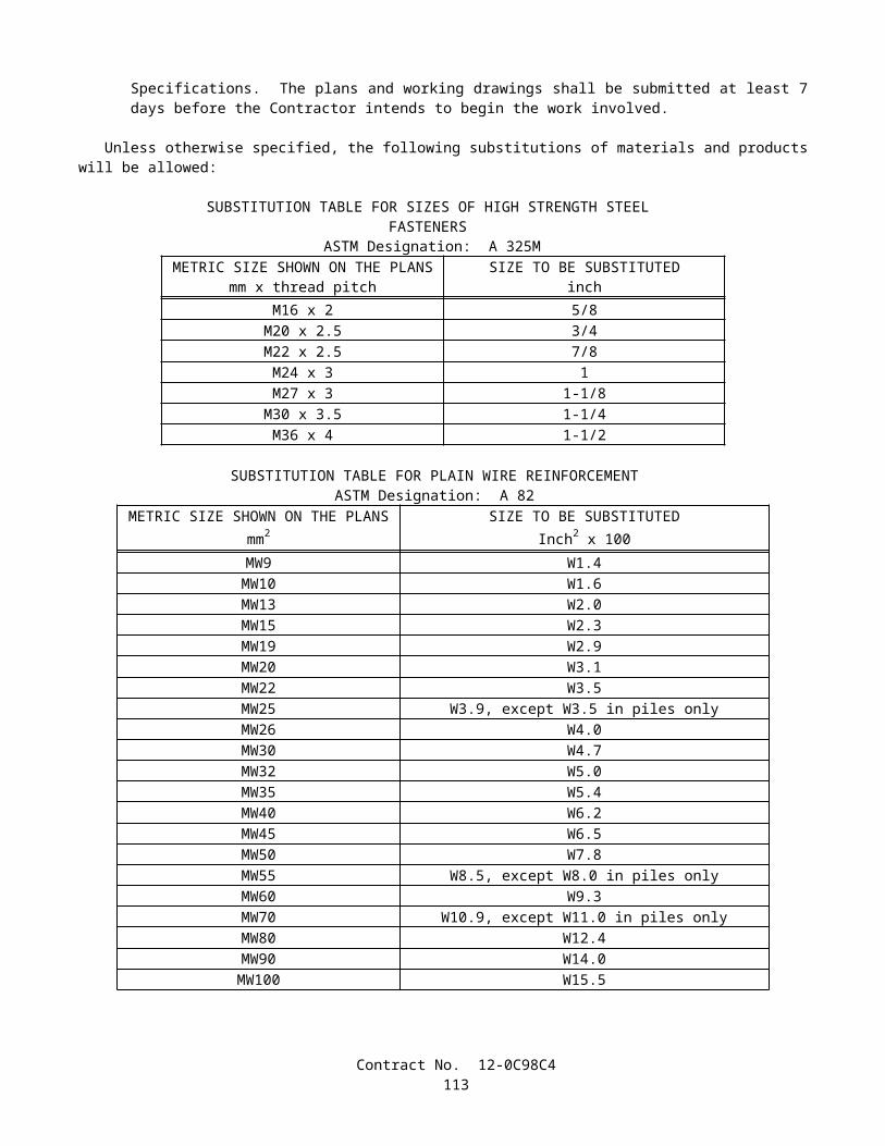
IMPORTED TOPSOIL CHARACTERISTICS
PARAMETER VALUEpH range 5.2 to 7.00
Organic matter 1.5 to 4.0%Magnesium 39 kg per ha, minimum
Phosphorus (P2O5) 84 kg per ha, minimumPotassium (K2O) 95 kg per ha, minimum
Soluble salts 500 ppmClay 10 to 25%Silt 30 to 55%
Sand 35 to 60%
Quality AssuranceQuality assurance conformance testing shall be performed by an independent laboratory in accordance with the
following table:
ASTM TESTING DESIGNATION
IMPORTED TOPSOIL(m3)
Moisture Density D1557 382Nuclear Density D2922 382Nuclear Water Content
D3017382
Moisture Content D2216/D4643
As necessary to check nuclear gauge
Particle size D422/D1140 382Atterberg Limits D4318 382
Permeability D2434 382 1Minimum one test per material type.
These testing frequencies may be increased at the discretion of the Engineer.
MulchMulch shall conform to the provisions in Section 20-2.08, "Mulch," of the Standard Specifications and these special
provisions.Mulch shall be shredded hardwood, and shall be aged 2 to 12 months minimum.
Gravel BackfillGravel backfill shall conform to these special provisions. Gravel backfill shall be AASHTO M-43, and shall be 15 mm –
50 mm size. Gravel backfill shall be bank-run river pea gravel.Quantities of gravel backfill will be measured by the cubic meter.The contract price paid per cubic meter for gravel backfill shall include full compensation for furnishing all labor,
materials, tools, equipment, and incidentals, and for doing all the work involved in applying gravel backfill, complete in place, as shown on the plans, as specified in the Standard Specifications and these special provisions, and as directed by the Engineer.
Quality AssuranceQuality assurance conformance testing shall be performed by an independent laboratory in accordance with the
following table:
Contract No. 12-0C98C4115
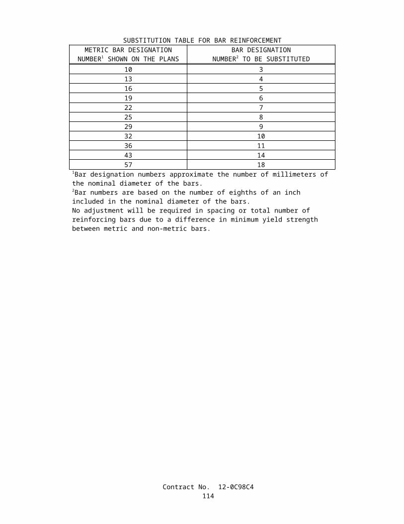
MATERIAL TESTING FREQUENCY1
ASTM TESTING DESIGNATION
GRAVEL(m3)
Moisture Density D1557Nuclear Density D2922Nuclear Water Content
D3017Moisture Content
D2216/D4643 Particle size D422/D1140 1,500Atterberg Limits D4318
Permeability D2434 1,500 1Minimum one test per material type.
These testing frequencies may be increased at the discretion of the Engineer.
APPLICATIONSeed (bioretention and bioswale) materials shall be applied as follows:
A. Seed (bioretention and bioswale) shall be applied by a dry method at the rate of 20.3 kg per hectare (slope measurement). Seed (bioretention and bioswale) shall not be applied with hydro-seeding equipment.
MAINTENANCEAreas to receive seed (bioretention and bioswale) shall be maintained by the Contractor from the time the seed
(bioretention and bioswale) is applied to the time of acceptance of the contract, provided however, that the contract will not be accepted unless the seed (bioretention and bioswale) area has been satisfactorily maintained for at least 180 working days after seed (bioretention and bioswale) has been applied.
Seed (bioretention and bioswale) areas shall be watered as necessary to maintain the seed (bioretention and bioswale) area in a healthy condition.
Weeds within the seed (bioretention and bioswale) areas shall be killed and removed before the weeds exceed 50 mm in length. Weeds shall be controlled by hand pulling or spot spraying. Pesticides to be used for weed control shall be submitted to the Engineer not less than 2 weeks prior to the pesticide's intended use. Pesticides not approved by the Engineer shall not be used.
Bioretention and bioswale areas shall be mowed to 150 mm height prior to acceptance of contract.Trash, debris, weeds, and mowed material within the seed (bioretention and bioswale) areas shall be removed and
disposed of outside the highway right of way in conformance with the provisions in Section 7-1.13, "Disposal of Material Outside the Highway Right of Way," of the Standard Specifications.
Seed for (bioretention and bioswale) areas shall be reapplied if the bare area exceeds 20% of the total seeded area as determined by the Engineer. Reseeding work, if required by the Engineer, will be paid for as extra work as provided in Section 4-1.03D of the Standard Specifications.
Seed (bioretention and bioswale) will be measured by the kilogram. The weight will be determined by the Engineer from marked mass and sack count or from scale weighings.
The contract price paid per kilogram for seed (bioretention and bioswale) shall include full compensation for furnishing all labor, materials, tools, equipment, and incidentals, and for doing all the work involved in obtaining and applying seed (bioretention and bioswale), complete in place, including maintenance as shown on the plans, as specified in the Standard Specifications and these special provisions, and as directed by the Engineer.
Full compensation for maintenance of seed (bioretention and bioswale) areas shall be considered as included in the contract price paid per kilogram for seed (bioretention and bioswale) and no additional compensation will be allowed therefor.10-1.21 ASPHALT CONCRETE
Asphalt concrete shall be Type B and shall conform to the provisions in Section 39, "Asphalt Concrete," of the Standard Specifications and these special provisions.
The aggregate for Type B asphalt concrete shall conform to the 19-mm maximum, medium grading specified in Section 39-2.02, "Aggregate," of the Standard Specifications.
Contract No. 12-0C98C4116

The asphalt content of the asphalt mixture will be determined in conformance with the requirements in California Test 379, or in conformance with the requirements in California Test 382.
Paint binder (tack coat) shall be applied to existing surfaces to be surfaced and between layers of asphalt concrete, except when eliminated by the Engineer.
Paint binder (tack coat) shall be paving asphalt conforming to the provisions in Section 39-4.02, "Prime Coat and Paint Binder (Tack Coat)," and Section 92, "Asphalts," of the Standard Specifications. The grade of paving asphalt to be used as paint binder will be determined by the Engineer.
Paint binder (tack coat) shall be, at the option of the Contractor, either slow-setting asphaltic emulsion, rapid-setting asphaltic emulsion or paving asphalt. Slow-setting asphaltic emulsion and rapid-setting asphaltic emulsion shall conform to the provisions in Section 39-4.02, "Prime Coat and Paint Binder (Tack Coat)," and the provisions in Section 94, "Asphaltic Emulsions," of the Standard Specifications. When paving asphalt is used for paint binder, the grade will be determined by the Engineer. Paving asphalt shall conform to the provisions in Section 39-4.02, "Prime Coat and Paint Binder (Tack Coat)," and the provisions in Section 92, "Asphalts," of the Standard Specifications.
Paint binder (tack coat) shall be applied in the liter per square meter range limits specified for the surfaces to receive asphalt concrete in the tables below. The exact application rate within the range will be determined by the Engineer.
Application Rates for Asphaltic Emulsion Paint Binder (Tack Coat) on Asphalt Concrete (except Open Graded) and on Portland Cement Concrete Pavement (PCCP)
Type of surface to receivepaint binder (tack coat)
Slow-Setting Asphaltic EmulsionL/m2(Note A)
Rapid-Setting Asphaltic EmulsionL/m2(Note B)
Dense, compact surfaces, between layers, and on PCCP
0.20 – 0.35 0.10 – 0.20
Open textured, or dry,aged surfaces
0.35 – 0.90 0.20 – 0.40
Note A: Slow-setting asphaltic emulsion is asphaltic emulsion diluted with additional water. Water shall be added and mixed with the asphaltic emulsion (containing up to 43 percent water) so the resulting mixture contains one part asphaltic emulsion and not more than one part added water. The water shall be added by the emulsion producer or at a facility that has the capability to mix or agitate the combined blend.Note B: Undiluted rapid-setting asphaltic emulsion.
Application Rates for Paint Binder (Tack Coat) onAsphalt Concrete (except Open Graded) and on Portland Cement
Concrete Pavement (PCCP)Type of surface to receive paint binder (tack coat) Paving Asphalt
L/m2
Dense, compact surfaces, between layers, and on PCCP
0.05 – 0.10
Open textured, or dry, aged surfaces 0.10 – 0.25
Application Rates for Asphaltic Emulsion Paint Binder (Tack Coat) on Open Graded Asphalt ConcreteType of surface to receive
paint binder (tack coat)Slow-Setting Asphaltic Emulsion
L/m2(Note A)Rapid-setting Asphaltic Emulsion
L/m2(Note B)Dense, compact surfacesand between layers
0.25 – 0.50 0.10 – 0.25
Open textured, or dry,aged surfaces
0.50 – 1.10 0.25 – 0.55
Note A: Slow-setting asphaltic emulsion is asphaltic emulsion diluted with additional water. Water shall be added and mixed with the asphaltic emulsion (containing up to 43 percent water) so the resulting mixture contains one part asphaltic emulsion and not more than one part added water. The water shall be added by the emulsion producer or at a facility that has the capability to mix or agitate the combined blend.Note B: Undiluted rapid-setting asphaltic emulsion.
Contract No. 12-0C98C4117

Application Rates for Paint Binder (Tack Coat) on Open Graded Asphalt Concrete
Type of surface to receive paint binder (tack coat) Paving AsphaltL/m2
Dense, compact surfaces and between layers 0.05 – 0.15Open textured, or dry, aged surfaces 0.15 – 0.30
When asphaltic emulsion is used as paint binder (tack coat), asphalt concrete shall not be placed until the applied asphaltic emulsion has completely changed color from brown to black.
At the Contractor's option longitudinal joints may be constructed using a device attached to the screed that will form a tapered notched wedge in a single pass. Longitudinal joints constructed with a tapered notched wedge shall be compacted to a minimum relative compaction of 93 percent. If longitudinal joints are constructed in this manner, the Contractor shall conduct quality control testing in conformance with the provisions in Section 6-3.02, "Testing By Contractor," of the Standard Specifications, and provide results that include the following:
A. Relative compaction values of the completed longitudinal joints tested using a nuclear gauge which has been calibrated and correlated with core densities in conformance with the requirements in California Test 375 Parts 1 and 2.
B. Nuclear density values taken at the rate of one test for each 200-meter section along the completed longitudinal joint. The Contractor shall select random locations for testing within each 200-meter section.
C. Nuclear density values taken at the centerline of the completed longitudinal joint, 150 mm from the upper vertical notch after the adjacent lane is placed and prior to opening the pavement to traffic.
D. Maximum density test results.E. Relative compaction values of the longitudinal joint determined as the ratio of the average of the nuclear density
values taken from each 200-meter section and the maximum density test results.
Relative compaction values shall be determined each day the joint is completed and delivered to the Engineer within 24 hours of testing. If the relative compaction of one day's production is less than 90 percent, placement of the tapered notched wedge shall not continue until the Contractor has notified the Engineer of the adjustment that will be made in order to meet the specified relative compaction. If the relative compaction for 3 day's production is less than 90 percent, the Contractor shall notify the Engineer and suspend use of the tapered notched wedge device.
The Engineer will determine relative compaction values for the completed longitudinal joint at the completion of paving as follows:
A. The Engineer will determine relative compaction by using 150-mm diameter cores obtained within the 0.3-m section of pavement at the completed longitudinal joint.
B. The Contractor shall obtain two 150-mm diameter cores taken 150 mm from the upper vertical notch of the completed longitudinal joint for every 1000 m along the completed longitudinal joint at locations designated by the Engineer. Cores shall be obtained after the adjacent lane is placed and prior to opening the pavement to traffic. Cores shall be obtained in the presence of the Engineer and shall be marked to identify the test sites.
C. The Contractor shall deliver the cores to the Engineer. One core will be used for determination of the relative density and one core will be used for dispute resolution.
D. The Engineer will determine the bulk specific gravity of the cores in conformance with the requirements of California Test 308 Method A.
E. Relative compaction will be calculated as the ratio of the average of the core densities from each day's production to the maximum density test value determined in conformance with California Test 375, Part 6.
Quantities of asphalt concrete placed in the completed longitudinal joint that fail to meet the relative compaction requirements of these special provisions will be subject to reduced compensation. The reduction in compensation shall be determined as follows:
A. Quantity = 0.3 m x 1000 m x (thickness of the layer placed) x (maximum density test value) x (relative compaction value).
B. Reduction in compensation = Quantity x (reduction factor) x (contract item price).C. The reduction factor will be determined using the following table:
Contract No. 12-0C98C4118

Relative Compaction (Percent)
Reduced Compensation Factor
Relative Compaction (Percent)
Reduced Compensation Factor
93.0 0.000 91.4 0.06292.9 0.002 91.3 0.06892.8 0.004 91.2 0.07592.7 0.006 91.1 0.08292.6 0.009 91.0 0.09092.5 0.012 90.9 0.09892.4 0.015 90.8 0.10892.3 0.018 90.7 0.11892.2 0.022 90.6 0.12992.1 0.026 90.5 0.14292.0 0.030 90.4 0.15791.9 0.034 90.3 0.17591.8 0.039 90.2 0.19691.7 0.044 90.1 0.22591.6 0.050 90.0 0.30091.5 0.056
Quantities of asphalt concrete placed in the completed longitudinal joint that meet the relative compaction requirements of these special provisions will not be measured as part of the quantity of asphalt concrete placed in the paved lane and will not be subject to reduced compensation or removal as determined by the relative compaction of the lane widths involved.
In addition to the cores taken every 1000 m along the completed longitudinal joint, the Contractor shall take 150-mm diameter cores every 3000 m approximately 0.9-m and 2.7 m perpendicular from the 1000 m core test sites. Cores may be taken on either side of the completed longitudinal joint. The Contractor shall mark core samples to identify the test sites. The Contractor shall determine the bulk specific gravity of each core in conformance with California Test 308 Method A and relative compaction as specified in these special provisions. Results of this testing shall be for reporting only.
10-1.22 CONCRETE STRUCTURESPortland cement concrete structures shall conform to the provisions in Section 51, "Concrete Structures," of the Standard
Specifications.
10-1.23 REINFORCEMENTReinforcement shall conform to the provisions in Section 52, "Reinforcement," of the Standard Specifications and these
special provisions.The Department's mechanical splices prequalified list can be found at the following internet site:
http://www.dot.ca.gov/hq/esc/approved_products_list/
The provisions of "Welding Quality Control" of these special provisions shall not apply to resistance butt welding.At the option of the Contractor, sample splices for all work shall be either 1) removed from the completed lot, or 2)
prepared in the same manner as specified in Section 52-1.08 "Splicing," of the Standard Specifications for ultimate prequalification sample splices and control bars.
When joining new reinforcing bars to existing reinforcement, sample splices shall be made using only the deformation pattern of the new reinforcement to be spliced.
At the option of the Contractor, any splices at the locations listed below may be encased in concrete prior to having the QCM review, approve, and forward each Production Test Report to the Engineer. Should the Contractor exercise this option, it is expressly understood that the Contractor will not be relieved of the Contractor's responsibility for incorporating material in the work that conforms to the requirements of the plans and specifications. Material not conforming to these requirements will be subject to rejection.
A. All Work
Bar reinforcement shown on the plans to be galvanized shall be galvanized in conformance with the provisions in Section 75-1.05,"Galvanizing," of the Standard Specifications.
Contract No. 12-0C98C4119

10-1.24 PLASTIC PIPEPlastic pipe shall conform to the provisions in Section 64, "Plastic Pipe," of the Standard Specifications and these special
provisions. The contract unit price paid per Meter for 300 mm Plastic Pipe, 600 mm Plastic Pipe, and 750 mm Plastic Pipe shall
include full compensation for furnishing all labor, materials, tools, equipment, and incidentals and for doing all the work involved in 300 mm Plastic Pipe, 600 mm Plastic Pipe, and 750 mm Plastic Pipe, including all necessary fittings and coupling systems as shown on the plans, complete in place, as specified in the Standard Specifications and these special provisions, and as directed by the Engineer.
10-1.25 PLASTIC UNDERDRAIN PIPEPlastic underdrain pipe shall conform to the provisions in Section 68, "Subsurface Drains," of the Standard
Specifications and these special provisions. The contract unit price paid per meter for 150 mm Plastic Underdrain Pipe shall include full compensation for furnishing
all labor, materials, tools, equipment, and incidentals and for doing all the work involved in installing the 150 mm Plastic Underdrain Pipe, including all necessary fittings and coupling systems as shown on the plans, complete in place, as specified in the Standard Specifications and these special provisions, and as directed by the Engineer.
10-1.26 REINFORCED CONCRETE PIPEReinforced concrete pipe shall conform to the provisions in Section 65, "Reinforced Concrete Pipe," of the Standard
Specifications and these special provisions.Where embankment will not be placed over the top of the pipe, a relative compaction of not less than 85 percent shall be
required below the pipe spring line for pipe installed using Method 1 backfill in trench, as shown on Standard Plan A62D. Where the pipe is to be placed under the traveled way, a relative compaction of not less than 90 percent shall be required unless the minimum distance between the top of the pipe and the pavement surface is the greater of 1.2 m or one half of the outside diameter of the pipe.
Except as otherwise designated by classification on the plans or in the specifications, joints for culvert and drainage pipes shall conform to the plans or specifications for standard joints.
When reinforced concrete pipe is installed in conformance with the details shown on Revised Standard Plan A62DA, the fifth paragraph of Section 19-3.04, "Water Control and Foundation Treatment," of the Standard Specifications shall not apply.
When solid rock or other unyielding material is encountered at the planned elevation of the bottom of the bedding, the material below the bottom of the bedding shall be removed to a depth of 1/50 of the height of the embankment over the top of the culvert, but not less than 150 mm nor more than 300 mm. The resulting trench below the bottom of the bedding shall be backfilled with structure backfill material in conformance with the provisions in Section 19-3.06, "Structure Backfill," of the Standard Specifications.
The excavation and backfill below the planned elevation of the bottom of the bedding will be paid for as extra work as provided in Section 4-1.03D, "Extra Work," of the Standard Specifications.
The Outer Bedding shown on Revised Standard Plan A62DA shall not be compacted prior to placement of the pipe. The contract unit price paid per meter for 600 mm reinforced concrete pipe, and 900 mm reinforced concrete pipe shall
include full compensation for furnishing all labor, materials, tools, equipment, and incidentals, and for doing the work involved in installing 600 mm reinforced concrete pipe and 900 mm reinforced concrete pipe, as shown on the plans, as specified in the Standard Specifications and these special provisions, and as directed by the Engineer.
10-1.27 CORRUGATED METAL PIPECorrugated metal culverts shall conform to the provisions in Section 66, "Corrugated Metal Pipe," of the Standard
Specifications and these special provisions.Asphaltic mastic coating or polymeric sheet coating substituted for bituminous coating shall be placed on the outside and
inside surfaces of the pipe.Corrugated metal pipe shall be fabricated from zinc-coated steel sheet.
10-1.28 CORRUGATED METAL PIPE RISERCorrugated Metal Pipe Riser shall conform to the provisions in Section 66, "Corrugated Metal Pipe," and Section 70,
"Miscellaneous Facilities," of the Standard Specifications and these special provisions.The corrugated metal pipe riser and debris rack cage shall be galvanized. Galvanizing shall conform to the provisions in
Section 75-1.05, "Galvanizing," of the Standard Specifications.The corrugated metal pipe riser shall be watertight, except the orifices as shown on the plans and the opening at the top
of the riser. All joints and bolt holes in the riser shall be sealed to provide watertightness as shown on the plans.
Contract No. 12-0C98C4120

The contract price paid per meter for 1200 mm corrugated metal pipe riser shall include full compensation for furnishing all labor, materials, tools, equipment, and incidentals, and for doing all the work involved in constructing the 1200 mm corrugated metal pipe riser, complete in place, including vertical riser pipe, horizontal section of corrugated metal pipe, watertightness, reinforced concrete pipe, structure excavation, structure backfill, and ladder as shown on the plans, as specified by in the Standard Specifications and these special provisions, and as directed by the Engineer.
10-1.29 PERFORATED PLASTIC PIPE UNDERDRAINPerforated Plastic Pipe underdrains shall conform to the provisions in Section 68-1, "Underdrains," of the Standard
Specifications.The contract unit price paid per meter for 150mm perforated plastic pipe underdrain shall include full compensation for
furnishing all labor, materials, tools, equipment, and incidentals, and for doing the work involved in installing 150mm perforated plastic pipe underdrain, as shown on the plans, as specified in the Standard Specifications and these special provisions, and as directed by the Engineer.
10-1.30 MISCELLANEOUS FACILITIES1200 mm Precast Concrete Pipe Manhole and Drainage Facility (Gross Solids Removal Device) shall conform to the
provisions in Section 70, "Miscellaneous Facilities," of the Standard Specifications and these special provisions.
DRAINAGE FACILITY (GROSS SOLIDS REMOVAL DEVICE)Drainage Facility (Gross Solids Removal Device (GSRD)) shall consist of furnishing and installing Gross Solids
Removal Device, including blank sections of pipe with one full diameter opening at top of pipe; louvered sections of pipe with doors, hinges, hinge stops and handles; gaskets, couplings, anchors, and all appurtenances; all as shown on the plans or as directed by the Engineer and as specified in the specifications and these special provisions.
One gross solids removal device size (600 mm) shall be provided as shown on the plans and as specified.The pipe section of the gross solids removal device conform to the provisions in Section 70, "Miscellaneous Facilities,"
of the Standard Specifications, for welded steel pipe. The pipe shall have a wall thickness of 5 mm and shall have louvered openings as shown on the plans.
All steel components of the gross solids removal device, except reinforcement, shall be galvanized. Galvanizing shall conform to the provisions in Section 75-1.05, "Galvanizing," of the Standard Specifications. All metals shall be galvanized at fabrication shop before delivery to job site.
Gross solids removal device shall be measured and paid for by the meter.Concrete shall be measured and paid for by the cubic meter of concrete as provided in Section 51, "Concrete Structures,"
of the Standard Specifications for minor structures.Miscellaneous iron and steel and galvanizing shall be measured and paid for at the contract price per kilogram as
provided in Section 75, "Miscellaneous Metal," of the Standard Specifications.Full compensation for reinforcing steel, structure excavation and structure backfill shall be considered as included in the
contract price paid per cubic meter for minor concrete (minor structure) and no separate payment will be made therefor.The above prices and payments shall include full compensation for furnishing and installing all labor, materials, tools,
equipment, and incidentals, and for doing the work involved in constructing and installing the drainage facility (Gross Solids Removal Device), complete in place, as shown on the plans, and as specified in the Standard Specifications and these special provisions, and as directed by the Engineer.
1200 MM PRECAST CONCRETE PIPE MANHOLEThe contract unit price paid for 1200 mm precast concrete pipe manhole shall include full compensation for furnishing
all labor, materials, tools, equipment, and incidentals, and for doing the work involved in installing the 1200 mm precast concrete pipe manhole, as shown on the plans, as specified in the Standard Specifications and these special provisions, and as directed by the Engineer.
10-1.31 MISCELLANEOUS IRON AND STEELMiscellaneous iron and steel shall conform to the provisions in Section 75, "Miscellaneous Metal," of the Standard
Specifications and these special provisions.The contract unit price paid for miscellaneous iron and steel shall include full compensation for furnishing all labor,
materials, tools, equipment, and incidentals, and for doing the work involved in providing miscellaneous iron and steel, as shown on the plans, as specified in the Standard Specifications and these special provisions, and as directed by the Engineer.
10-1.32 STAINLESS STEEL WIRE MESHStainless steel wire mesh shall conform to these special provisions.
Contract No. 12-0C98C4121
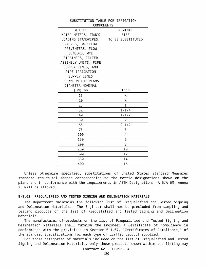
Stainless steel wire mesh shall be fabric conforming to the requirements in ASTM Designation: E2016-99. Stainless steel wire mesh shall be 5 mm by 5 mm and 1.2 mm diameter type 304 stainless steel. Stainless steel wire mesh shall be fastened to wire mesh support frame as shown on plans.
The contract price paid per square meter for stainless steel wire mesh shall include full compensation for furnishing all labor, materials, tools, equipment, and incidentals, and for doing all the work involved in furnishing and installing the stainless steel wire mesh, complete in place, as shown on the plans, as specified by in the Standard Specifications and these special provisions, and as directed by the Engineer.
10-1.33 GEOMEMBRANEGeomembrane shall function as a leak free water barrier to prevent infiltration. The geomembrane shall have the shape
and dimensions as shown on the plans. The dimensions shall be adequate to cover the facility, including transverse anchor trenches at the beginning and end of the facility and longitudinal anchor trenches along its length.
MATERIALS.Geomembrane shall be smooth on both sides. Geomembrane shall consist of a single ply material. The major polymer
material component of the geomembrane shall be either polyvinyl chloride (PVC), linear low density polyethylene (LLDPE), very low density polyethylene (VLDPE), or other comparable flexible materials or combinations thereof. The geomembrane shall be flexible enough to bend in anchor trenches and to conform to subgrade irregularities by its own weight, in ambient job-site air temperatures, without any overburden placed on it, and without additional heating and bending.
Geomembrane shall be manufactured from either virgin raw materials or from a combination of virgin and recycled materials. None of the materials, whether virgin or recycled, shall contain biodegradable filler materials that degrade the physical or chemical characteristics of the finished roll products, such that they no longer function as leak-free water barriers. To confirm the absence of biodegradable filler materials, the engineer may order tests such as ASTM E 204 (Fourier Transformed Infrared Spectroscopy-FTIR) or other appropriate tests.
Geomembrane shall be free from holes or punctures and shall conform to the following requirements:
Specification RequirementGrab tensile strength at break, KiloNewtons, min. both machine and cross
directions (25 mm wide strip of material) ASTM Designation: D 882 *
0.267Elongation at break, percent (%) min. ASTM Designation: D 882 * 50
Toughness, kilonewtons, min. (Percent elongation x grab tensile strength)
example 0.30 kn x 100 % = 30 kN-%
17.8
Puncture resistance, kilonewtons, min. FTMS 101C Method 2031 * 0.13* or appropriate test method for a comparable geomembrane polymer
material
A Certificate of Compliance shall be furnished in accordance with the provision of Section 6-1.07, "Certificates of Compliance" of the Standard Specifications. It shall state that the geomembrane complies with all of the above conditions and material requirements.
SEAMSThere shall be all factory-seamed geomembrane(s) delivered to the job site.Geomembrane seams shall be leak free, as tested by the VACUUM BOX METHOD, ASTM 4437, or other comparable
seam test for the specific polymer. Leaky geomembrane, as determined by the engineer, shall be replaced at the expense of the contractor.
Geomembrane sheets shall be welded (heat or ultrasonic or other), or shall be solvent-bonded with a material that is compatible with the geomembrane as recommended by the manufacturer, to meet the required shape and dimensions as
Contract No. 12-0C98C4122

shown on the plans. Actual bonding along the entire length of any seam shall be at least 25 mm wide. Additional overlapped material is permitted, but will not be considered as additional area for compensation. Filler-sealer compounds shall not be permitted for factory or field seams.
INSTALLATIONGeomembrane shall conform to the following installation requirements:
SubgradeSubgrade shall be free of sharp protruding materials and objects.
Anchor trenchesThe transverse and longitudinal edges of the geomembrane shall be anchored in trenches600millimeters deep, as shown
on the plans.
DamageNo construction equipment shall drive directly on the geomembrane. Damage to the geomembrane that results from the
Contractor's vehicles, equipment, or operations shall be replaced or repaired by the Contractor at his expense. Damaged geomembrane shall be either completely replaced or repaired with new material according to the specifications for SEAMS, except 450 mm of patch material shall extend beyond any damage.
MEASUREMENTGeomembrane shall be measured by the square meter of area covered including anchor trench dimensions. Overlapped
area of factory seams, field seams, or overlapped joints shall not be included.
PAYMENTThe contract price paid per square meter for geomembrane shall include full compensation for furnishing all labor,
materials, tools, equipment, and incidentals, and for doing all the work involved in installing the geomembrane, complete in place, as shown on the plans, as specified in the Standard Specifications and these special provisions, and as directed by the Engineer. There shall be no extra compensation for overlaps.
10-1.34 GEOTEXTILE Geotextile shall consist of a separate geotextile and shall be placed as shown on the plans and in conformance with these
special provisions.
INSTALLATIONInstallation shall be done at the locations as shown on the plans.
JointsSegments of fabric shall be shingled as shown on the plans. Overlaps shall be a minimum of 300 millimeters.
DamageNo construction equipment shall drive directly on the geotextile . Damage to the material resulting from the Contractor's
vehicles, equipment, or operations shall be replaced or repaired by the Contractor at his expense. Any damaged material shall be either completely replaced or repaired with new material according to the above specifications for joints, except that 450 mm of patching material shall extend beyond any damage.
MATERIALSGeotextile cushion fabric shall be a nonwoven, needle-formed fabric, free of any needles which may have broken off
during manufacturing. It can be manufactured from either virgin polymer materials, (for example, polypropylene or polyester), recycled materials, or a combination of recycled and virgin polymer materials, (for example, polyester polyethylene terephthalate "PETE"). None of the materials, whether virgin or recycled, shall contain biodegradable filler materials that degrade the physical or chemical characteristics of the finished roll products. To confirm the absence of biodegradable filler materials the engineer may order tests such as ASTM E 204 (Fourier Transformed Infrared Spectroscopy-FTIR) or other appropriate tests.
Geotextile shall meet the following physical requirements:
Contract No. 12-0C98C4123
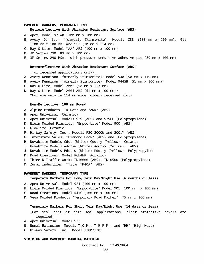
Property Value ASTM Designation*Weight (grams/square meter), min 271 D 5261Grab Tensile Strength (kN), min
(25 mm grip min, both directions)0.89 D 4632
Elongation at Break (percent), min 50 D 4632Toughness (kN-%), min
(percent elongation times grab tensile strength)53
* or appropriate test method for comparable geotextile polymer material
A Certificate of Compliance shall be furnished in accordance with the provision of Section 6-1.07, "Certificates of Compliance" of the Standard Specifications.
MEASUREMENTGeotextile shall be measured by the square meter of area covered . Overlapped area of field joints shall not be included.
PAYMENTThe contract price paid per square meter for geotextile shall include full compensation for furnishing all labor, materials,
tools, equipment, and incidentals, and for doing all the work involved in installing the geotextile , complete in place, as shown on the plans, as specified in the Standard Specifications and these special provisions, and as directed by the Engineer. There shall be no extra compensation for overlaps.
10-1.35 COMPOSITE TURF REINFORCEMENT MATComposite Turf Reinforcement Mat shall conform to these special provisions.The composite turf reinforcement mat (C-TRM) shall be a machine produced mat of 100% synthetic fiber matrix
incorporated into a permanent three-dimensional netting structure.The matrix shall be a consistent thickness of synthetic fibers evenly distributed across the entire width of the matting and
stitch bonded between a heavy duty ultraviolet (UV) stabilized bottom net with 15 x 15 mm (approximate) openings, and a heavy duty UV stabilized top net with 15 x 15 mm (approximate) openings. The nettings shall be stitched together on 40 mm (approximate) centers with UV stabilized polypropylene thread to form a permanent three-dimensional structure.
All mats shall be manufactured with a colored thread stitched along both outer edges (approximately 50- 125 mm from the edge) as an overlap guide for adjacent mats.
The composite turf reinforcement mat shall have the following physical properties:
Matrix---100% UV Stable Polypropylene Fiber0.38 kg/m2 approximate weight
Top Netting---Heavy UV Stabilized Polypropylene2.44 kg/100 m2 approximate weight
Bottom Netting--- Heavy UV Stabilized Polypropylene1.47 kg/100 m2 approximate weight
Thread: Black UV Stabilized Polypropylene
Composite turf reinforcement mat shall be intended per permanent installation and be North American Green, P300, or equal.
Composite turf reinforcement mat shall be installed in accordance with engineer’s instructions, plans, blueprints, etc, and in a manner consistent with the installation instruction and recommendation of the manufacturer.
Composite Turf Reinforcement Mat shall be measured by the square meter of area covered. Overlapped area of field joints shall not be included.
The contract price paid per square meter of Composite Turf Reinforcement Mat shall include full compensation for furnishing all labor, materials, tools, equipment, and incidentals, and for doing the work involved in furnishing and installing the Composite Turf Reinforcement Mat as shown on the plans, as specified in the Standard Specifications and these special provisions, and as directed by the Engineer.
Contract No. 12-0C98C4124

10-1.36 METERING MANHOLE WITH HS FLUMEMetering manhole with HS flume shall conform to the contract plans and these special provisions. Plans and wording drawings for the prefabricated metering manhole with HS flume shall be provided to the Engineer,
following requirements of Standard Specifications 5-1.02, "Plans and Working Drawings." Manufacturer’s installation instructions shall also be included in the plans and working drawings.
The metering manhole with HS flume shall be stored indoors or in weather protected area until installation. Nylon or fabric slings only shall be used in conjunction with a spreader bar to lift or move the metering manhole with HS flume. Damage to the metering manhole with HS flume shall be repaired at the Contractor’s expense, or at the option of the Engineer, the damaged metering manhole with HS flume shall be replaced at no addition compensation.
The metering manhole shall meeting the following material and configuration requirements.
Property Requirement Test MethodSize 1200 mm diameter VisualType Parshall
Construction Single piece, prefabricated VisualMaterial Fiberglass reinforced plastic, 30%
fiberglass by weight minimum; multiple layers
ASTM D 3753
Matrix material Unsaturated, single source and batch Isophtalic polyester resin
Color Non-pigmented resinUV resistance 15 mm UV resistant gel on
exterior surfacesMaterial Tensile strength 95 MPa ASTM D 638Material Flexural strength 180 MPa ASTM D 790Material Flexural modulus 680 MPa ASTM D 790
Stiffness 8650 MPa ASTM D 2412Material Barcol Hardness 40 ASTM D 2538
Wall thickness Manhole: 15 mm minimumHS Flume: 5 mm minimum
measured
Finish of inside surface Free of projections, smooth, no blisters larger than 15 mm
diameter, no crazing, delamination or fiber exposed, no
wrinkles greater than 3 mm in depth
visual
Finish of outside surface Free of projections, smooth, no blisters larger than 15 mm
diameter, no delamination or fiber exposed
visual
Hardware Stainless Steel
Construction:Integral fiberglass ladder bolted and glassed to the manhole wall with 40 mm by 40 mm pultruded fiberglass rungs with
a photoluminescent high visibility non-slip top surface and reinforced with threaded T-304 21 mm diameter stainless steel rods.
Integrally molded inlet and outlet polyvinyl chloride (PVC) stubs of 300 mm inlet and 600 mm outlet diameter laminated to both the interior and exterior surfaces of the manhole.
Flexible polyvinyl chloride (PVC) boots with stainless steel bands to connect 300 mm inlet and 600 mm outlet diameter manhole pipe stubs to 300 mm inlet and 600 mm polyvinyl chloride (PVC) style pipe. Inlet boot shall be eccentric. Outlet boot shall be concentric.
A 20 mm thick expanded polystyrene bead board shall be supplied to place under the manhole on the concrete slab. A 100 mm Fiberglass Reinforced Plastic integral mounting flange shall be molded to the base of the manhole barrel for
anchoring to the manhole to the concrete slab. An OSHA approved “Confined Space Entry” sign shall be applied to the interior surface of the manhole above the first
ladder rung (H-20 type) or on the underside of the manhole top. Contract No. 12-0C98C4
125

One 50 mm National Pipe Thread coupling to facilitate the installation of sample or bubble tubing, electrical power, or other cabling into the manhole.
Run sample lines and electrical lines in separate conduits. Cross-talk may occur across unshielded electrical lines. A watertight aluminum access hatch 750 mm wide x 600 mm deep and rated for pedestrian loading (14364 Pa live load)
for mounting in a 1200 mm diameter manhole. The access hatch shall be fabricated with structural grade aluminum diamond plate with a minimum thickness of 5 mm. The door shall be provided with a compression spring assist, automatic locking hold open arm, a stainless steel, recessed lift handle, and a staple for a user supplied padlock. All hardware is to be stainless steel.
A bituminous coating shall be applied to the frame exterior and the hatch. The access hatch shall be mounted to the manhole through the use of a reinforced fiberglass cover and shall be attached
with stainless steel hardware. A T-304 pull-up automatic locking stainless steel ladder assist shall be as high as the manhole 2.5 m and shall ship
attached to the Fiberglass Reinforced Plastic ladder rungs. A set of T-304 stainless steel anchor bolts shall be provided to level the flume.The flume shall meeting the following material and configuration requirements.
Property Requirement Test MethodSize 300 mm diameter VisualType HS flume
Construction Single piece, prefabricated VisualMaterial Fiberglass reinforced plastic, 30%
fiberglass by weight minimum; multiple layers
ASTM D 3753
Matrix material Unsaturated, single source and batch Isophtalic polyester resin
Color Non-pigmented resinUV resistance 15 mm UV resistant gel on
exterior surfacesMaterial Tensile strength 95 MPa ASTM D 638Material Flexural strength 180 MPa ASTM D 790Material Flexural modulus 680 MPa ASTM D 790Material Barcol Hardness 50 ASTM D 2538
Wall thickness 5 mm minimum measuredFinish of inside surface Gloss inside surface, free of
irregularitiesvisual
Hardware Stainless Steel
FLUME TYPE:HS FLUME type, 300 mm size with integral inlet and outlet end adapters. Pultruded fiberglass reinforced plastic bracing at top of flume (inlet and outlet), T-304 stainless steel hardware. 50 mm (minimum) top and end flanges. Molded-in stiffening ribs, maximum 300 mm center to center spacing. 5-mil Mylar, laminated, high visibility staff gauge: Graduated in meters with 2 millimeters divisions. Removable T-304 3 mm outside diameter (O.D.) stainless steel bubble tube. Approach section: 1.5 m long 300 mm wide. Inlet bulkhead.A certificate of compliance shall be furnished in accordance with the provision of Section 6-1.07, "Certificates of
Compliance," of the Standard Specifications for the above materials and configuration requirements.
INSTALLATION:Metering manhole with HS flume shall be installed in accordance with the manufacturer’s recommendations, these
special provisions, and as directed by the Engineer. The metering manhole shall be installed plumb and true, free of twist or warp, within the tolerances specified by the
manufacturer. Nylon or fabric slings only shall be used in conjunction with a spreader bar to lift or move the manhole. The Contractor shall verify the direction of flow through the flume prior to installation. After placement, the HS Flume shall be leveled from side to side and from front to back.
Contract No. 12-0C98C4126

The polyvinyl chloride boots shall not be lubricated. The Contractor shall grout any void areas between the flume to fully support the flume. Backfilling around the metering manhole with HS flume shall be conducted according the Standard Specification 19-
3.06, "Structure Backfill," of the Standard Specifications and these special provisions. Material used for backfill shall be free of large soil lumps, rock, concrete, and other deleterious debris, and shall meet the
following gradation:
Sieve Size Percentage Passing2.36 mm 1001.18 mm 70-90600 µm 40-75300 µm 10-35150 µm 0-1075 µm 0-5
Groundwater or surface runoff shall not be permitted to accumulate in an open excavation around the manhole when it has not been completely backfilled.
All surfaces of the metering manhole with HS flume shall be cleaned in accordance with the manufacturer’s instructions after all placement and backfilling has been completed.
All Trash and debris shall be removed, and the site shall be left in a clean condition.The contract price paid per unit for metering manhole with HS flume shall include full compensation for furnishing all
labor, materials, tools, equipment, and incidentals, and for doing all the work involved in constructing and installing the metering manhole with HS flume, complete in place, as shown on the plans, as specified in these special provisions, and as directed by the Engineer.
PARSHALL FLUME:Parshall flume shall conform to the contract plans and these special provisions.Parshall flume shall be stored indoors or in weather protected area until installation. The Parshall Flume shall be protected from construction traffic and damage. The Parshall Flume shall be handled with care during transport and installation, and fabric slings and spreader bars shall
be used during all hoisting of the Parshall Flume. Damage to the Parshall Flume shall be repaired at the Contractor’s expense, or at the option of the Engineer, the
damaged Parshall Flume shall be replaced at no addition compensation. Parshall flume shall meeting the following material and configuration requirements.
Property Requirement Test MethodSize 300 mm VisualType Parshall
Construction Single piece VisualMaterial Fiberglass reinforced plastic, 30%
fiberglass by weight minimumASTM D 3753
Matrix material Isophtalic polyester resinUV resistance 15 mil coating minimum
Material Tensile strength 95 MPa ASTM D 638Material Flexural strength 180 MPa ASTM D 790Material Flexural modulus 680 MPa ASTM D 790Material Barcol Hardness 50 ASTM D 2538
Wall thickness 5 mm minimum measuredFinish of inside surface Glossy visual
Hardware Stainless Steel
CONSTRUCTION:Pultruded fiberglass reinforced plastic bracing at top of flume (inlet and outlet), T-304 stainless steel hardware. 50 mm (minimum) top and end flanges. Molded-in stiffening ribs, maximum 300 mm center to center spacing. Anchor clips drilled for 20 mm, pultruded fiberglass reinforced plastic. 5-mil Mylar, laminated, high visibility staff gauge: Graduated in meters with 2 mm divisions.
Contract No. 12-0C98C4127

Removable T-304 3 mm outside diameter (O.D.) stainless steel bubble tube. Inlet and outlet end adapters. Inlet and or outlet flat-faced flanges: Size: Inlet - 600 mm and Outlet - 750 mm, Style: Plastic. Inlet and outlet pipe stubs with flexible polyvinyl chloride boots and stainless steel bands: Size: Inlet - 600 mm and
Outlet - 750 mm. Bull’s-eye level. A certificate of compliance shall be furnished in accordance with the provision of Section 6-1.07, "Certificates of
Compliance," of the Standard Specifications for the above materials and configuration requirements.
INSTALLATION:Parshall flume shall be installed in accordance with contract plans, the manufacturer’s recommendations, these special
provisions, and as directed by the Engineer. Parshall flume shall be installed plumb. The upstream (flat) floor of the flume (the crest) shall be level from side to side
and from front to back. The crest shall be upstream and the sidewalls shall be vertically plumb. The Parshall Flume shall be embedded in concrete, limiting pour concrete to a maximum 300 mm lifts, internally brace
the flume as necessary to ensure bowing does not occur. The Parshall Flume shall be anchored in accordance with manufacturer’s recommendations and the plans. Care shall be taken to ensure that the Parshall Flume does not move during concrete pours. The use of a vibrator shall be
minimized as excessive use may bulge or distort the flume sidewalls and bottom. The Parshall Flume shall be installed in the correct orientation of flow. All areas between the Parshall Flume and the concrete pad shall be grouted to fully support the flume. After completion of the installation, all surfaces shall be cleaned in accordance with the manufacturer’s instructions, and
all trash and debris shall be removed, and the site shall be left in a clean condition. The contract price paid per unit for 300 mm Parshall Flume shall include full compensation for furnishing all installation
hardware, labor, materials, tools, equipment, and incidentals, and for doing all the work involved in constructing and installing the 300 mm Parshall Flume, complete in place, as shown on the plans, as specified by in the Standard Specifications and these special provisions, and as directed by the Engineer.
10-1.37 CHAIN LINK FENCEChain link fence shall be Type CL-1.8 and shall conform to the provisions in Section 80, "Fences," of the Standard
Specifications. The contract unit price paid per meter for chain link fence (Type CL-1.8) shall include full compensation for furnishing
all labor, materials, tools, equipment, and incidentals, and for doing the work involved in installing chain link fence (Type CL-1.8), as shown on the plans, as specified in the Standard Specifications and these special provisions, and as directed by the Engineer.
10-1.38 CHAIN LINK GATEChain link gate shall be Type CL-1.8 and shall conform to the provisions in Section 80, "Fences," of the Standard
Specifications. The contract unit price paid for chain link gate (Type CL-1.8) shall include full compensation for furnishing all labor,
materials, tools, equipment, and incidentals, and for doing the work involved in installing chain link gate (Type CL-1.8), as shown on the plans, as specified in the Standard Specifications and these special provisions, and as directed by the Engineer.
Contract No. 12-0C98C4128