frp structural pultrusion technical specifications
12
1 frp structural pultrusion technical specifications composite fibre technologies
Transcript of frp structural pultrusion technical specifications

1
frp structural pultrusion technical
specificationsc o m p o s i t e f i b r e t e c h n o l o g i e s

COMPOSITE FIBRE TECHNOLOGIES (CFT) wagner.com.au2
TABLE OF CONTENTS
Liability Disclaimer..............................................................................................................................................................................................................1. Introduction ............................................................................................................................................................................................................................2. Specification Requirement Inputs ............................................................................................................................................................................. 2.1 General ................................................................................................................................................................................................................ 2.1.1 Summary and Scopes of Work ................................................................................................................................................ 2.1.2 Submittals....................................................................................................................................................................................... 2.2 Design Criteria ..................................................................................................................................................................................................... 2.3 Material Properties.......................................................................................................................................................................................... 2.4 Mechanical Properties ..................................................................................................................................................................................... 2.5 Durability and Design Life........................................................................................................................................................................... 2.6 Accessories ............................................................................................................................................................................................................ 2.7 Quality Assurance............................................................................................................................................................................................... 2.7.1 Certification ...................................................................................................................................................................................... 2.7.2 Manufacturing Tolerances.......................................................................................................................................................... 2.7.3 Batch Testing.....................................................................................................................................................................................3. Sizing and Part Numbers of Wagners Pultrusion .......................................................................................................................................... 4. Specifying Wagners Pultrusion ...................................................................................................................................................................................5. Wagners Drawing Notes ..................................................................................................................................................................................................
2344444556677778910
The information and recommendations contained in this document have been prepared with due care and is offered for the purpose of assisting architects, project managers, and design engineers in the development of specifications for the use of glass fibre reinforced polymer structural pultrusion products (“The Product”). Wagners CFT Manufacturing Pty Ltd (“the Company”) reserves the right to change, cease manufacture or alter any of the products represented in this Guide.
Whilst every effort has been made to ensure that this document is in accordance with current practices, it is not intended as an exhaustive statement of all relevant information. Wagners CFT Manufacturing Pty Ltd accepts no responsibility for errors in, omissions from the manual, nor designs or work done, or omitted to be done, in reliance on this document. To the fullest extent permitted by law, the Company expressly disclaims all and any liability for direct or indirect damage, injury or loss however caused, to any person, whether as purchaser or otherwise in relation to any product manufactured or recommended by the Company.
liability disclaimer
COMPOSITE FIBRE TECHNOLOGIES (CFT) wagner.com.au3
1 INTRODUCTION
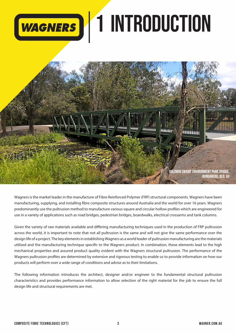
Wagners is the market leader in the manufacture of Fibre Reinforced Polymer (FRP) structural components. Wagners have been manufacturing, supplying, and installing fibre composite structures around Australia and the world for over 16 years. Wagners predominantly use the pultrusion method to manufacture various square and circular hollow profiles which are engineered for use in a variety of applications such as road bridges, pedestrian bridges, boardwalks, electrical crossarms and tank columns.
Given the variety of raw materials available and differing manufacturing techniques used in the production of FRP pultrusion across the world, it is important to note that not all pultrusion is the same and will not give the same performance over the design life of a project. The key elements in establishing Wagners as a world leader of pultrusion manufacturing are the materials utilised and the manufacturing technique specific to the Wagners product. In combination, these elements lead to the high mechanical properties and assured product quality evident with the Wagners structural pultrusion. The performance of the Wagners pultrusion profiles are determined by extensive and rigorous testing to enable us to provide information on how our products will perform over a wide range of conditions and advise as to their limitations.
The following information introduces the architect, designer and/or engineer to the fundamental structural pultrusion characteristics and provides performance information to allow selection of the right material for the job to ensure the full design life and structural requirements are met.
BALDWIN SWAMP environment park BRIDGE,bundaberg, qld, au
COMPOSITE FIBRE TECHNOLOGIES (CFT) wagner.com.au4
specificationrequirementinputs
2
A. The Contractor shall provide full details of the FRP materials, including all associated manufacturing processes, test certificates, adhesive, and fasteners.
B. Relevant construction and/or structural drawings for all FRP components shall be submitted to the Design Engineer for approval in accordance with the requirements as per this specification. Fabrication of components shall not commence until written approval from the Design Engineer and/or the Principal is received.
C. The Contractor shall provide any certificates or quality management plans in accordance with the requirements as detailed in Section 2.7.
A. The design of the FRP components shall be certified by a suitably qualified engineer with experience in designing fibre composite structures.
B. The design of the FRP components shall be in accordance with “Structural Design of Polymer Composites, EUROCOMP Design Code and Handbook,” edited by John L Clark.
C. The design of the FRP components shall be in accordance with governing building codes, standard, and the requirements of the Principal as applicable.
D. Substitution of any component or modification of the system shall be made only when approved by the Architect, Design Engineer or the Principal.
2.2 design criteria
2.1.1 Summary and Scopes of Work
2.1 GENERAL
A. The work under the Contract relates to the supply of FRP structural pultrusion components as specified herein.
B. The Contractor is responsible for all labour, materials, equipment, and incidentals governed by this specification to manufacture the FRP components in accordance with any structural drawings provided by the Principal.
2.1.2 Submittals
COMPOSITE FIBRE TECHNOLOGIES (CFT) wagner.com.au5
specificationrequirementinputs
2
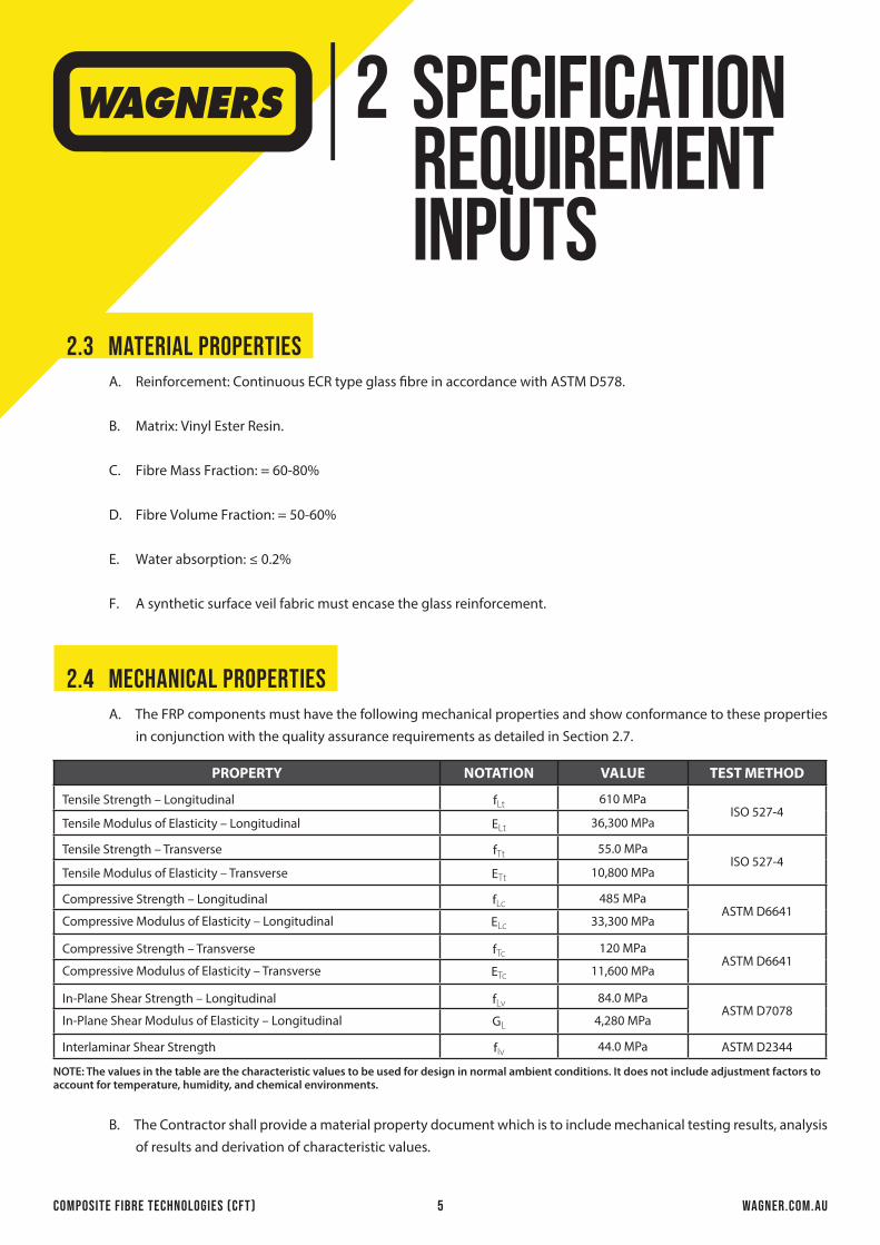
A. Reinforcement: Continuous ECR type glass fibre in accordance with ASTM D578.
B. Matrix: Vinyl Ester Resin.
C. Fibre Mass Fraction: = 60-80%
D. Fibre Volume Fraction: = 50-60%
E. Water absorption: ≤ 0.2%
F. A synthetic surface veil fabric must encase the glass reinforcement.
2.3 material properties
A. The FRP components must have the following mechanical properties and show conformance to these properties in conjunction with the quality assurance requirements as detailed in Section 2.7.
2.4 mechanical properties
B. The Contractor shall provide a material property document which is to include mechanical testing results, analysis of results and derivation of characteristic values.
PROPERTY NOTATION VALUE TEST METHOD
Tensile Strength – Longitudinal fLt 610 MPaISO 527-4
Tensile Modulus of Elasticity – Longitudinal ELt 36,300 MPa
Tensile Strength – Transverse fTt 55.0 MPaISO 527-4
Tensile Modulus of Elasticity – Transverse ETt 10,800 MPa
Compressive Strength – Longitudinal fLc 485 MPaASTM D6641
Compressive Modulus of Elasticity – Longitudinal ELc 33,300 MPa
Compressive Strength – Transverse fTc 120 MPaASTM D6641
Compressive Modulus of Elasticity – Transverse ETc 11,600 MPa
In-Plane Shear Strength – Longitudinal fLv 84.0 MPaASTM D7078
In-Plane Shear Modulus of Elasticity – Longitudinal GL 4,280 MPa
Interlaminar Shear Strength fIv 44.0 MPa ASTM D2344
NOTE: The values in the table are the characteristic values to be used for design in normal ambient conditions. It does not include adjustment factors to account for temperature, humidity, and chemical environments.

COMPOSITE FIBRE TECHNOLOGIES (CFT) wagner.com.au6
specificationrequirementinputs
2
A. Design life to be a minimum of 100 years.
B. A UV-resistant coating must be applied to all FRP components. The coating material must have undergone 20,000+ hours of QUV-B testing in accordance with ASTM G154. The testing must show no degradation to the structural integrity of the FRP components.
C. Apply a waterproofing compound or compatible resin coating to seal any end cut fibres that are a result of drilling or cutting of the FRP components.
2.5 durability and design life
A. Unless noted otherwise, all bolts, brackets, rivets and screws must be grade A4/316 stainless steel, property class 70 to ISO 3506.
B. All FRP hollow sections must be reinforced with anti-crush inserts to resist crushing loads from bolt tightening and to enhance bolted connection capacities.
2.6 accessories
CFT TESTING LAB
BAIO road BRIDGE,Wyhanbeel, qld, au

COMPOSITE FIBRE TECHNOLOGIES (CFT) wagner.com.au7
specificationrequirementinputs
2
2.7.1 Certification
2.7 quality assurance
A. The Contractor must be certified to ISO 9001 Quality Management System.
2.7.2 Manufacturing Tolerances
A. Manufacturing tolerances are to be in accordance with ASTM D3917.
B. The visual quality of the pultruded FRP components shall be in accordance with ASTM D4385.
2.7.3 Batch Testing
A. The Contractor must have in place a sampling test plan in accordance with AS 1199.1. The test plan shall identify the testing facility, product tested, quantity/frequency of testing and types of tests carried out for each batch.
B. Batch testing of the pultrusion is to be performed by the manufacturer or an accredited third-party testing laboratory at regular intervals as stated on their sampling test plan to ensure the products continued adherence with the technical requirements as specified herein.
C. The Contractor must provide a written Certificate of Compliance on all orders guaranteeing the pultrusion has been tested and complies with the technical requirements.
D. The Contractor must be able to provide to the Principal, individual test results and/or a report for each batch as required and as stated in their test plan.

8
COMPOSITE FIBRE TECHNOLOGIES (CFT) wagner.com.au
3 sizing and part numbers ofwagners pultrusion
PRODUCT CODE PROFILE TYPE DIMENSIONSDesignation Outside
Corner Radius
Inside Corner Radius
MassExternal Surface
Area
GrossSection
AreaDepth Width Thick.
d b t ro ri per m per m Ag
mm mm mm mm mm kg/m m2/m mm2
GV36-RH075x5.0Rectangular Hollow
SectionsWCFT 100 75 5.0 10.0 4.75 3.21 0.333 1,580
GV36-SH100x5.2 Square Hollow Sections
WCFT 100 100 5.2 10.0 4.75 3.87 0.383 1,910
GV36-SH125x6.4 WCFT 125 125 6.4 10.0 4.75 6.03 0.483 2,970
GV36-BR200x5.2
Bonded Rectangular Beams
WCFT 200 100 5.2 10.0 4.75 7.74 0.606 3,810
GV36-BR300x5.2 WCFT 300 100 5.2 10.0 4.75 11.6 0.828 5,720
GV36-BR400x5.2 WCFT 400 100 5.2 10.0 4.75 15.5 1.050 7,620
GV36-BR500x5.2 WCFT 500 100 5.2 10.0 4.75 19.3 1.270 9,530
GV36-BR250x6.4 WCFT 250 125 6.4 10.0 4.75 12.1 0.756 5,940
GV36-BR375x6.4 WCFT 375 125 6.4 10.0 4.75 18.1 1.030 8,910
GV36-BR500x6.4 WCFT 500 125 6.4 10.0 4.75 24.1 1.300 11,900
GV36-BR625x6.4 WCFT 625 125 6.4 10.0 4.75 30.1 1.570 14,800
Rectangular Hollow Section
Square Hollow Section
Bonded Rectangular Beams
8
COMPOSITE FIBRE TECHNOLOGIES (CFT) wagner.com.au9
specifyingwagnerspultrusion
4
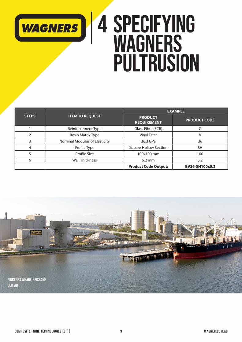
STEPS ITEM TO REQUESTEXAMPLE
PRODUCTREQUIREMENT PRODUCT CODE
1 Reinforcement Type Glass Fibre (ECR) G
2 Resin Matrix Type Vinyl Ester V
3 Nominal Modulus of Elasticity 36.3 GPa 36
4 Profile Type Square Hollow Section SH
5 Profile Size 100x100 mm 100
6 Wall Thickness 5.2 mm 5.2
Product Code Output: GV36-SH100x5.2
PINKENBA WHARF, brisbaneqld, au

COMPOSITE FIBRE TECHNOLOGIES (CFT) wagner.com.au10
WAGNERSDRAWING NOTES
5COMPOSITE FIBRE NOTES:
B1. ALL MATERIAL AND WORKMANSHIP SHALL COMPLY WITH WAGNERS CFT MANUFACTURING PTY LTD (WCFT), WORK INSTRUCTIONS, INSTALLATION GUIDES AND QUALITY ASSURANCE STANDARDS.
B2. UNLESS OTHERWISE NOTED OR APPROVED, COMPOSITE MATERIALS FOR USE IN THIS PROJECT SHALL BE MANUFACTURED FROM ECR GLASS AND VINYL ESTER RESIN CONFORMING WITH ISO 9002 STANDARD.
B3. ALL MEMBERS SHALL BE IN SOUND CONDITION FREE FROM PITTING, DE-LAMINATIONS AND OTHER DEFECTS WHICH ARE LIKELY TO IMPAIR THE STRUCTURAL CAPACITY OF THE MEMBERS.
B4. WHERE MEMBERS ARE TO BE BOLTED A WCFT INSERT OR BUSH IS REQUIRED.
- ALL WCFT INSERTS & BUSHES UNLESS NOTED OTHERWISE ARE TO BE: GLUED
- WCFT INSERTS & BUSHES THAT ARE REQUIRED TO BE GLUED SHALL BE GLUED USING APPROVED POLYURETHANE ADHESIVE SUPPLIED BY WAGNERS AND APPLIED AS PER WAGNERS WORK INSTRUCTIONS.
B5. APPLY A WATERPROOFING COMPOUND OR COMPATIBLE RESIN COATING TO SEAL ANY END CUT FIBRES AS A RESULT OF DRILLING, CUTTING OR DAMAGE TO THE COMPOSITE FIBRE PROFILES.
B6. ALL EXPOSED ENDS OF COMPOSITE MEMBERS SHALL HAVE ENDCAPS INSTALLED AS PER WAGNERS WORK INSTRUCTIONS AND INSTALLATION GUIDES.
B7. WHERE ADAPTER ENDCAPS ARE SHOWN, THEY ARE TO BE INSTALLED ON SITE AS PER WAGNERS WORK INSTRUCTIONS AND INSTALLATION GUIDES. ENDCAPS ARE TO BE LOCALLY TRIMMED SO THAT THEY DON’T INTERFERE WITH BRACKETS.
B8. ALL MEMBERS TO BE MARKED WITH THE MEMBER NUMBER, IF ENDCAPS ARE TO BE INSTALLED IN THE FACTORY THEY ARE TO BE STAMPED OTHERWISE IT IS TO BE LEGIBLY WRITTEN WITH A WHITE PEN.
B9. FINISHES & COLOUR:
- ALL MEMBERS IN DIRECT CONSTANT SUNLIGHT ARE TO BE COATED WITH THE APPROVED TWO PACK FLUOROPOLYMER COATING APPLIED AS PER WAGNERS WORK INSTRUCTIONS AND INSTALLATION GUIDES.
- ALL OTHER MEMBERS ARE TO BE COATED WITH THE APPROVED TWO PACK ACRYLIC POLYURETHANE COATING APPLIED AS PER WAGNERS WORK INSTRUCTIONS AND INSTALLATION GUIDES.
- COLOUR OF ALL COMPOSITE MEMBERS TO BE = ______________
B10. AS FRP SECTIONS ARE ORTHOTROPIC THE EVALUATION AND UNDERSTANDING OF MATERIAL PROPERTIES WHEN DESIGNING COMPOSITE STRUCTURES IS PARAMOUNT. ALSO OF IMPORTANCE IS THE UNDERSTANDING OF HOW THESE MATERIAL PROPERTIES ARE USED. SECTION 7.2.2 OF AS1170.0 REQUIRES:
- WHEN CONSIDERING A LIMIT STATE OF COLLAPSE, RUPTURE OR EXCESSIVE DEFORMATION OF A STRUCTURE, SECTION, MEMBER OR CONNECTION IT SHALL BE CONFIRMED THAT: RD ≥ ED (WHERE RD = DESIGN CAPACITY (EQUAL TO ΦR) AND ED = DESIGN ACTION EFFECT (SEE CLAUSE 4.2) THE DESIGN CAPACITY (ΦR) IS A CAPACITY REDUCTION FACTOR (Φ) MULTIPLIED BY R - DEFINED IN AS1170.0 CL 1.5 AS THE “NOMINAL CAPACITY (BASED ON FIFTH PERCENTILE STRENGTH)”. TO COMPLY WITH THIS REQUIREMENT AND TO BE ABLE TO USE IN AN ENGINEER VALIDATED DESIGN, CHARACTERISTIC VALUES OF MATERIAL PROPERTIES SHALL BE CALCULATED IN ACCORDANCE WITH ASTM D7290. THIS STANDARD DEFINES THE CHARACTERISTIC VALUE AS “A STATISTICALLY-BASED MATERIAL PROPERTY REPRESENTING THE 80% LOWER CONFIDENCE BOUND ON THE 5TH-PERCENTILE VALUE OF A SPECIFIED POPULATION”. REQUIRED MATERIAL PROPERTIES AND APPLICABLE TEST METHODS ARE LISTED IN THE TABLES. FOR EACH PROPERTY IN THESE TABLES A MINIMUM OF TEN TESTS CONDUCTED IN A NATA APPROVED OR AUSTRALIAN UNIVERSITY ARE REQUIRED BEFORE APPLYING THE PROCEDURE IN ASTM D7290 TO DETERMINE THE CHARACTERISTIC VALUE. AND ARE DETERMINED BASED ON THE FOLLOWING CONDITIONS:
• SHORT TERM LOADING• AMBIENT TEMPERATURE OF 23°C ± 2°C AND RELATIVE HUMIDITY OF 50 ± 10%• A NEUTRAL CHEMICAL ENVIRONMENT

COMPOSITE FIBRE TECHNOLOGIES (CFT) wagner.com.au11
PROPERTY NOTATION VALUE TEST METHOD
Tensile Strength ft 34.1 MPa ISO 527-2
Tensile Modulus Et 2409 MPa ISO 527-2
Lap Shear Strength fv 11.9 MPa ASTM D3161
Heat Deflection Temperature HDT 85°C ISO 75
NOTE:
1. The values in the table are based on a cure schedule of 24 hrs @ ambient + 8 hrs @ 80°C.
2. The values in the table are the design values to be used in normal ambient conditions. It does not include adjustment factors to account for temperature, humidity & chemical environments.
WAGNERSDRAWING NOTES
5WFCT COMPOSITE MATERIALS:
B12.
B13. THE MECHANICAL PROPERTIES OF WCFT GRADE GV36 SHS FRP MEMBERS ARE:
PROPERTY NOTATION VALUE TEST METHOD
Tensile Strength – Longitudinal fLt 610 MPa
ISO 527-4Tensile Modulus of Elasticity – Longitudinal ELt 36,300 MPa
Poisson’s Ratio – Longitudinal nL 0.28
Tensile Strength – Transverse fTt 55.0 MPa
ISO 527-4Tensile Modulus of Elasticity – Transverse ETt 10,800 MPa
Poisson’s Ratio – Transverse nT 0.09
Compressive Strength – Longitudinal fLc 485 MPaASTM D6641
Compressive Modulus of Elasticity – Longitudinal ELc 33,300 MPa
Compressive Strength – Transverse fTc 120 MPaASTM D6641
Compressive Modulus of Elasticity – Transverse ETc 11,600 MPa
In-Plane Shear Strength – Longitudinal fLv 84.0 MPaASTM D7078
In-Plane Shear Modulus of Elasticity – Longitudinal GL 4,280 MPa
Interlaminar Shear Strength fIv 44.0 MPa ASTM D2344
NOTE: The values in the table are the characteristic values to be used for design in normal ambient conditions. It does not include adjustment factors to account for temperature, humidity, and chemical environments.
WCFT BONDING ADHESIVE PROPERTIES:
WHERE MEMBERS ARE TO BE BONDED, MEMBERS SHALL BE BONDED USING APPROVED EPOXY ADHESIVE SUPPLIED BY WAGNERS AND APPLIED AS PER WAGNERS WORK INSTRUCTIONS.
B11.
COMPONENT MATERIAL MATERIAL
Reinforcement Continuous ECR Glass Fibre
Matrix Vinyl Ester Resin
Veil Thermoplastic Non-Woven
Additives Proprietary catalysts, mould release and polymer additives
NOTE: For further information, contact Wagners.
COMPOSITE FIBRE TECHNOLOGIES (CFT) wagner.com.au12
WAGNERSDRAWING NOTES
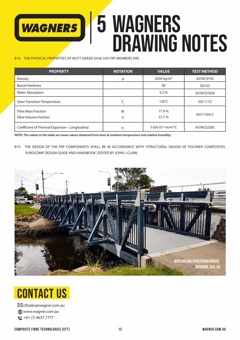
5THE PHYSICAL PROPERTIES OF WCFT GRADE GV36 SHS FRP MEMBERS ARE:
PROPERTY NOTATION VALUE TEST METHOD
Density p 2030 kg/m³ ASTM D792
Barcol Hardness 60 ISO 62
Water Absorption 0.2 % ASTM D7029
Glass Transition Temperature Tg
130°C ISO 1172
Fibre Mass Fraction
Fibre Volume Fraction
Wr
Vr
77.4 %
57.7 %ISO11359-2
Coefficient of Thermal Expansion - Longitudinal αL
5.03x10ˉ6 m/m/°C ASTM D2583
NOTE: The values in the table are mean values obtained from tests at ambient temperature and relative humidity.
B15. THE DESIGN OF THE FRP COMPONENTS SHALL BE IN ACCORDANCE WITH “STRUCTURAL DESIGN OF POLYMER COMPOSITES,
EUROCOMP DESIGN GUIDE AND HANDBOOK”, EDITED BY JOHN L CLARK.
B14.
contact us [email protected] www.wagner.com.au +61 (7) 4637 7777
mooloolaba pedestrian bridge,brisbane, qld, au