Front Jack Design - kth.diva-portal.org958420/FULLTEXT01.pdf · Front Jack Design - of a tunnel...
70
Front Jack Design - of a tunnel boring machine Petter Grelsson Master of Science Thesis MMK 2016:85 MKN 163 KTH Industrial Engineering and Management Machine Design SE-100 44 STOCKHOLM
-
Upload
phungnguyet -
Category
Documents
-
view
215 -
download
0
Transcript of Front Jack Design - kth.diva-portal.org958420/FULLTEXT01.pdf · Front Jack Design - of a tunnel...
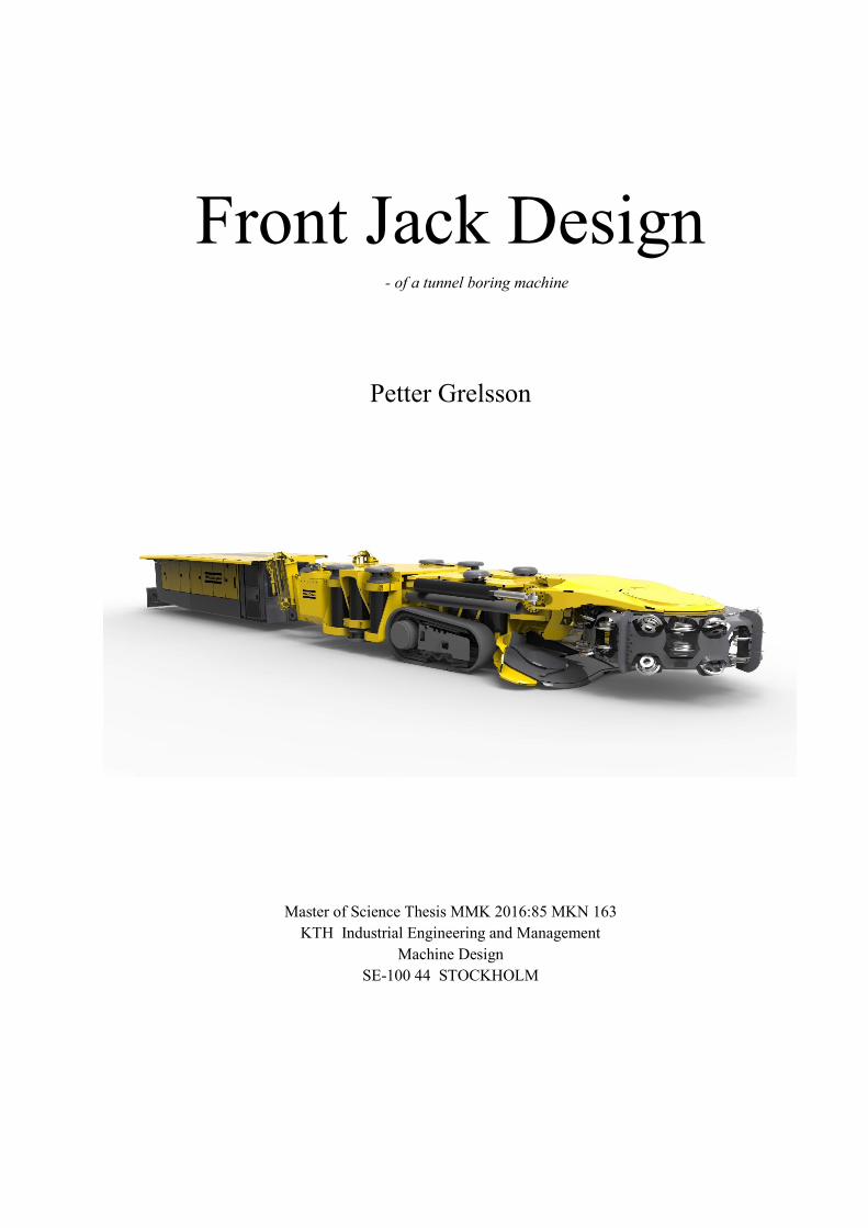
Front Jack Design - of a tunnel boring machine
Petter Grelsson
Master of Science Thesis MMK 2016:85 MKN 163
KTH Industrial Engineering and Management
Machine Design
SE-100 44 STOCKHOLM

1
Examensarbete MMK 2016:85 MKN 163
Konceptkonstruktion av främre stabilisatorer
- För en tunnelborrningsmaskin
Petter Grelsson
Godkänt
2016-06-15
Examinator
Ulf Sellgren
Handledare
Ulf Sellgren
Uppdragsgivare
Svea Teknik
Kontaktperson
Jacob Wollberg
Sammanfattning
Denna rapport är resultatet av ett examensarbete på KTHs master-program för maskinkonstruktion i
samarbete med Atlas Copco och Svea Teknik.
Atlas Copco utvecklar en tunnelborrningsmaskin som trycker sig framåt och glider på skidor under
borrning. Detta har visats sig ge stora friktionsförluster mellan det ojämna gruvgolvet och skidan vilket
gör att de behöver en alternativ lösning på detta problem som klarar lasterna från borrning och maskinens
egenvikt samt reducerar friktionen i maskinens längdriktning.
Konceptutvecklingen var indelad i fyra stora delsteg: konceptgenerering, val av koncept, vidareutveckling
och analys och utvärdering. Projektet avser endast konceptutveckling, ingen fullständig konstruktion.
Några komponenter kunde bli omkonstruerade av Atlas Copco vid behov, de främre stingrarna som håller
den stabil mot taket fick inte ändras, inga ritningar ritades, ingen detaljerad FEM-modellering och inte
alla externa komponenter blev valda.
Två koncept togs till vidareutveckling genom Pughs beslutsmatris: The Slide Guide och The Rocker
Bogie. CAD modeller ritades och blev analyserade med avseende på strukturella laster och
friktionskoefficienter jämfört med den befintliga lösningen. The Slide Guide klarar alla krav som kunde
jämföras och The Rocker Bogie klarade inte utrymmeskraven och skulle kräva omfattande
omkonstruktion av main body för att fungera. Koncepten blev utvärderade med hjälp av olika beräkningar
och FEM analys
Nyckelord: Mekanisk bergavverkning, framdrivning, minska friktion.

2
3
Master of Science Thesis MMK 2014:85 MKN 163
Front Jack Design
Petter Grelsson
Approved
2014-06-15
Examiner
Ulf Sellgren
Supervisor
Ulf Sellgren
Commissioner
Svea Teknik
Contact person
Jacob Wollberg
Abstract
This report is the result of a master thesis at KTH Machine Design in cooperation with Atlas Copco and
Svea Teknik.
Atlas Copco is developing a Tunnel Boring Machine that pushes itself forward on steel skids using a
torque tube when boring. This has proven to suffer from large frictional forces between the rough mine
floor and the skid and they need an alternative solution to hold the loads of the machine while boring and
reducing the friction when propelling itself forward.
The concept development was divided into four main stages, concept generation, concept selection,
further development, analysis and evaluation. The project includes only concept development, no
complete designs. Some parts could be redesigned by Atlas Copco if needed, the front stingers supporting
against the roof was not to be redesigned, no drawings was made, no detailed FEA modeling was done
and not all external components was chosen.
Two concepts where chosen for further development using the PUGH’s decision matrix, The Slide Guide
and The Rocker Bogie. CAD models was developed and analyzed regarding loads and friction compared
to the existing solution. The Slide Guide clears all requirements that could be measured and the Rocker
Bogie does not fit within the geometrical limits available without extensive redesign of the Main Body.
This was verified using calculations and structural FEA.
Keywords: mechanical rock excavation, propelling, reducing friction

4
5
FOREWORD
I would like to thank my supervisors Andreas Lundqvist, Bengt Johansson and Ulf Sellgren for all the
support I have received during this project. I would also like to thank Fredrik Saf and Atlas Copco for the
opportunity to do this project and for the great feedback on my designs. Lastly I would like to thank my
fellow master’s students Camila Svedmyr, Emil Grönkvist, Johan Lindestaf and the staff at Svea Teknik
for a very fun and interesting last semester.
Petter Grelsson
Stockholm, May, 2016

6
7
NOMENCLATURE
Notations Symbol Description
E Young´s modulus (Pa)
r Radius (m)
t Thickness (m)
m Mass (kg)
σs Yield stress (MPa)
g Constant of gravity (m/s2)
….. …….
Abbreviations
CAD Computer Aided Design
CAE Computer Aided Engineering
PLM Product Lifecycle Management
ProE Pro Engineer
PTC Software company, formerly Parametric Technology Corporation
FEA Finite Element Analysis
FEM Finite Element Method
KTH Royal Institute of Technology
QFD Quality Function Deployment
FDM Fused Deposition Modeling
MB Main Body
RB Rear Body
CH Cutting head
Expressions
Tramming A kind of propulsion, used within Atlas Copco
8
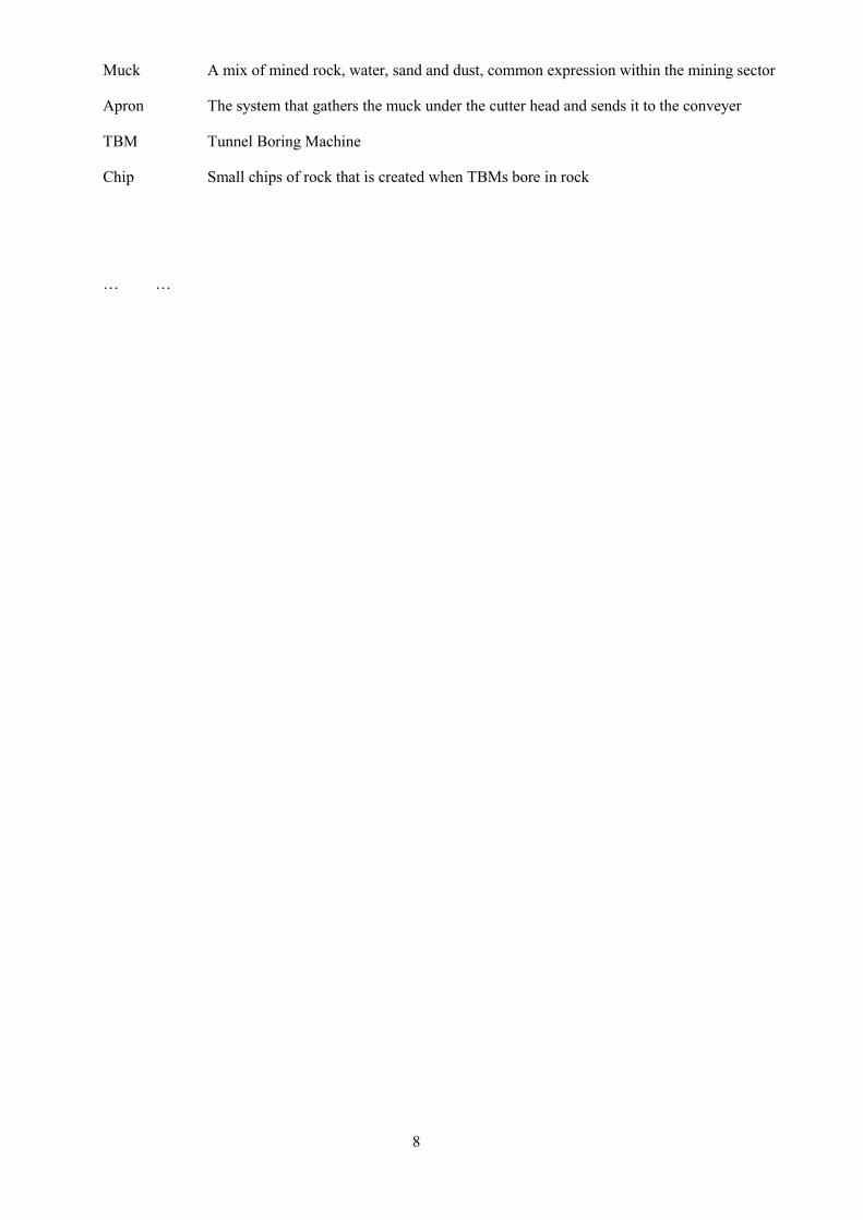
Muck A mix of mined rock, water, sand and dust, common expression within the mining sector
Apron The system that gathers the muck under the cutter head and sends it to the conveyer
TBM Tunnel Boring Machine
Chip Small chips of rock that is created when TBMs bore in rock
… …
9
CONTENTS
NOMENCLATURE 7
CONTENTS 9
1 INTRODUCTION 11
1.1 Background 11
1.2 Problem description 12
1.3 Delimitations 13
1.4 Method 13
2 FRAME OF REFERENCE 16
2.2 Reef miner 16
2.3 Maneuvering rough terrain 18
2.4 Journal bearings 20
3 METHODOLOGY AND RESULTS 23
3.1 Requirements 23
3.2 Concept generation 24
3.3 Concept evaluation 28
3.4 Rocker Bogie 29
3.5 Slide Guide 38
3.6 Results 50
4 DISCUSSION AND CONCLUSION 51
5 RECOMMENDATIONS AND FUTURE WORK 53
5.1 Recommendations for future work 53
REFERENCES 55
7 APPENDICES 57
APPENDIX A: QFD 58
APPENDIX C: Weight reducing proposal 60
APPENDIX D: Matlab code for link plate calculations 61
APPENDIX E: Matlab code for reset hydraulics 64
APPENDIX F: GANTT schedule 67

10
11
1 INTRODUCTION
An introduction to Atlas Copco and the mining industry methods of excavating mines as well as the
problem description, purpose, delimitations and methods that have been used
1.1 Background
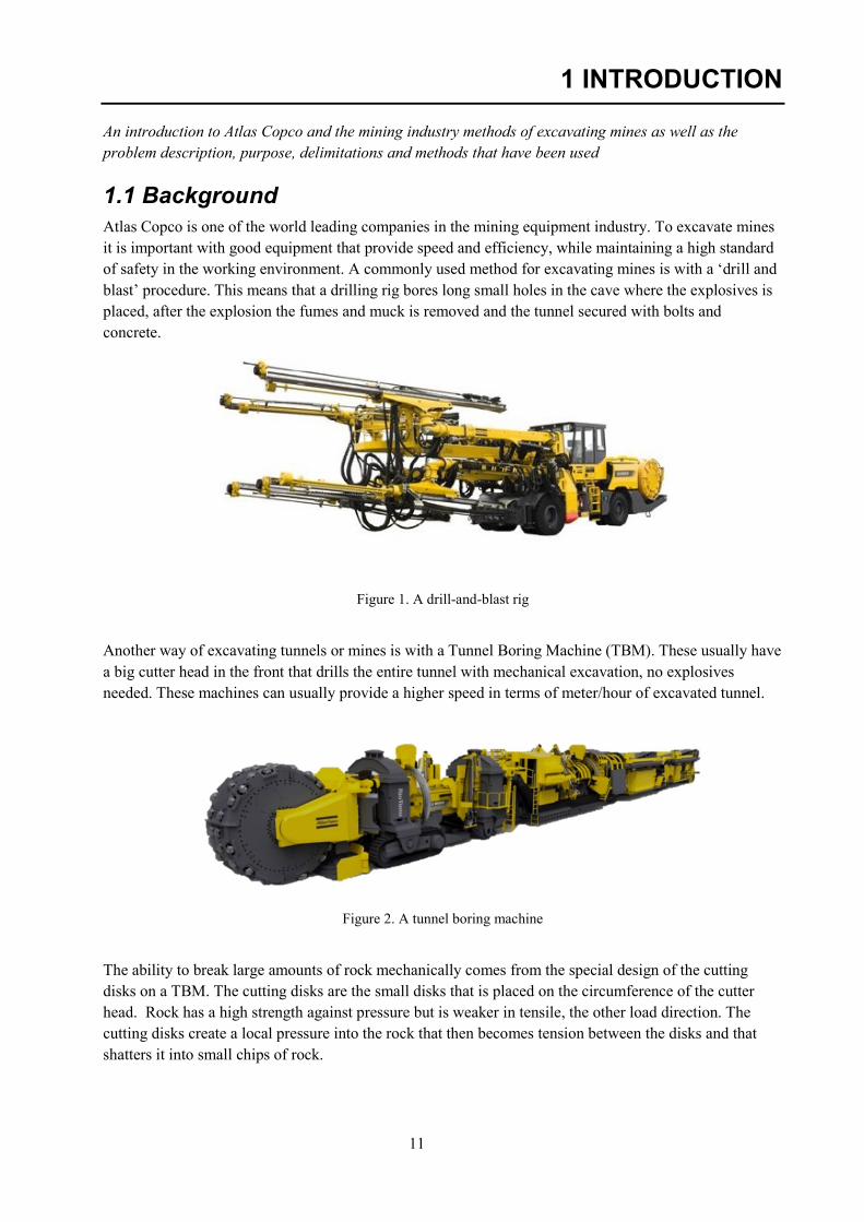
Atlas Copco is one of the world leading companies in the mining equipment industry. To excavate mines
it is important with good equipment that provide speed and efficiency, while maintaining a high standard
of safety in the working environment. A commonly used method for excavating mines is with a ‘drill and
blast’ procedure. This means that a drilling rig bores long small holes in the cave where the explosives is
placed, after the explosion the fumes and muck is removed and the tunnel secured with bolts and
concrete.
Figure 1. A drill-and-blast rig
Another way of excavating tunnels or mines is with a Tunnel Boring Machine (TBM). These usually have
a big cutter head in the front that drills the entire tunnel with mechanical excavation, no explosives
needed. These machines can usually provide a higher speed in terms of meter/hour of excavated tunnel.
Figure 2. A tunnel boring machine
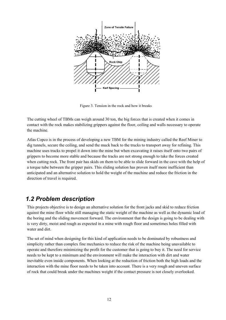
The ability to break large amounts of rock mechanically comes from the special design of the cutting
disks on a TBM. The cutting disks are the small disks that is placed on the circumference of the cutter
head. Rock has a high strength against pressure but is weaker in tensile, the other load direction. The
cutting disks create a local pressure into the rock that then becomes tension between the disks and that
shatters it into small chips of rock.
12
Figure 3. Tension in the rock and how it breaks
The cutting wheel of TBMs can weigh around 30 ton, the big forces that is created when it comes in
contact with the rock makes stabilizing grippers against the floor, ceiling and walls necessary to operate
the machine.
Atlas Copco is in the process of developing a new TBM for the mining industry called the Reef Miner to
dig tunnels, secure the ceiling, and send the muck back to the trucks to transport away for refining. This
machine uses tracks to propel it down into the mine but when excavating it raises itself onto two pairs of
grippers to become more stable and because the tracks are not strong enough to take the forces created
when cutting rock. The front pair has skids on them to be able to slide forward in the cave with the help of
a torque tube between the gripper pairs. This sliding solution has proven itself more inefficient than
anticipated and an alternative solution to hold the weight of the machine and reduce the friction in the
direction of travel is required.
1.2 Problem description
This projects objective is to design an alternative solution for the front jacks and skid to reduce friction
against the mine floor while still managing the static weight of the machine as well as the dynamic load of
the boring and the sliding movement forward. The environment that the design is going to be dealing with
is very dirty, moist and rough as expected in a mine with rough floor and sometimes holes filled with
water and dirt.
The set of mind when designing for this kind of application needs to be dominated by robustness and
simplicity rather than complex fine mechanics to reduce the risk of the machine being unavailable to
operate and therefore minimizing the profit for the customer that is going to buy it. The need for service
needs to be kept to a minimum and the environment will make the interaction with dirt and water
inevitable even inside components. When looking at the reduction of friction both the high loads and the
interaction with the mine floor needs to be taken into account. There is a very rough and uneven surface
of rock that could break under the machines weight if the contact pressure is not closely overlooked.
13
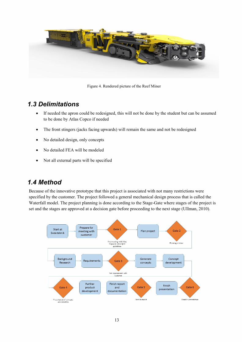
Figure 4. Rendered picture of the Reef Miner
1.3 Delimitations
If needed the apron could be redesigned, this will not be done by the student but can be assumed
to be done by Atlas Copco if needed
The front stingers (jacks facing upwards) will remain the same and not be redesigned
No detailed design, only concepts
No detailed FEA will be modeled
Not all external parts will be specified
1.4 Method
Because of the innovative prototype that this project is associated with not many restrictions were
specified by the customer. The project followed a general mechanical design process that is called the
Waterfall model. The project planning is done according to the Stage-Gate where stages of the project is
set and the stages are approved at a decision gate before proceeding to the next stage (Ullman, 2010).
14
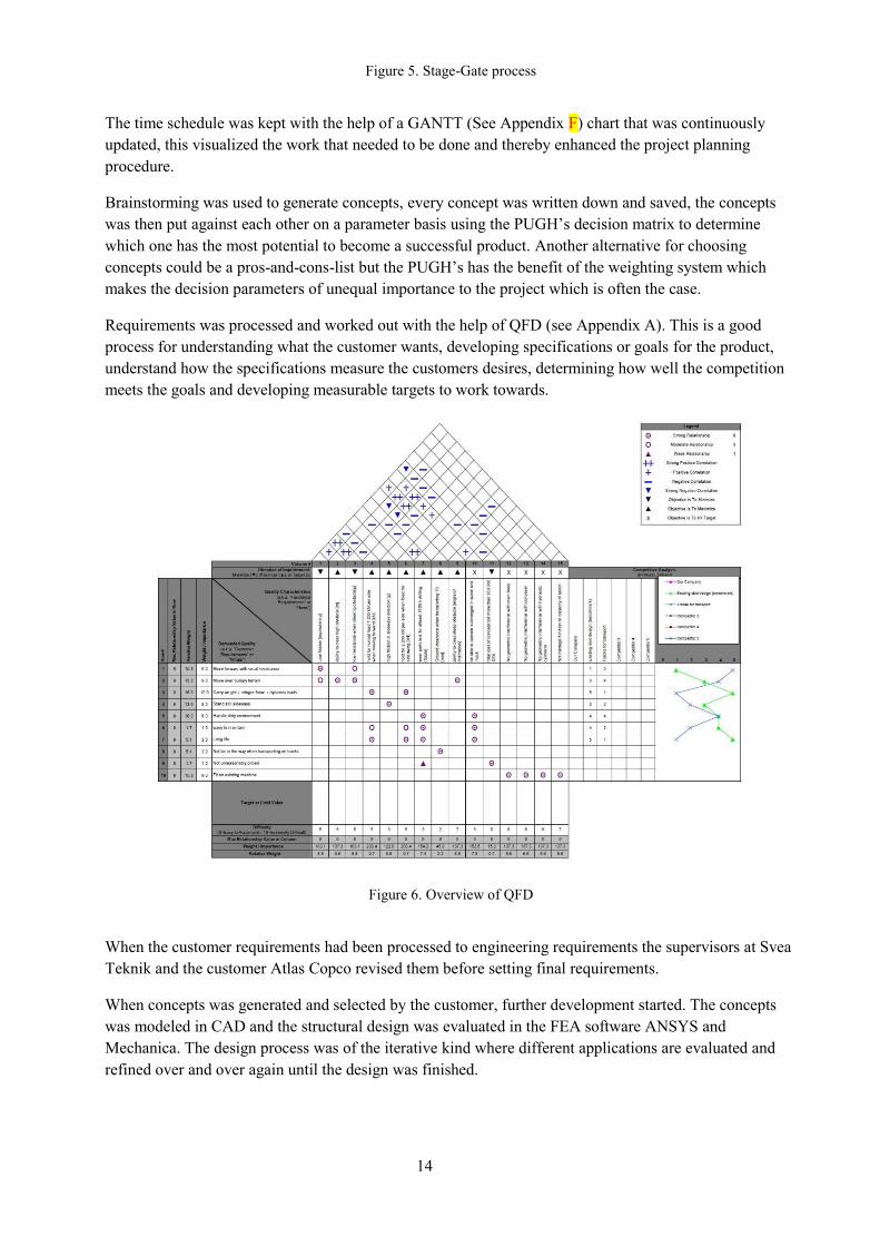
Figure 5. Stage-Gate process
The time schedule was kept with the help of a GANTT (See Appendix F) chart that was continuously
updated, this visualized the work that needed to be done and thereby enhanced the project planning
procedure.
Brainstorming was used to generate concepts, every concept was written down and saved, the concepts
was then put against each other on a parameter basis using the PUGH’s decision matrix to determine
which one has the most potential to become a successful product. Another alternative for choosing
concepts could be a pros-and-cons-list but the PUGH’s has the benefit of the weighting system which
makes the decision parameters of unequal importance to the project which is often the case.
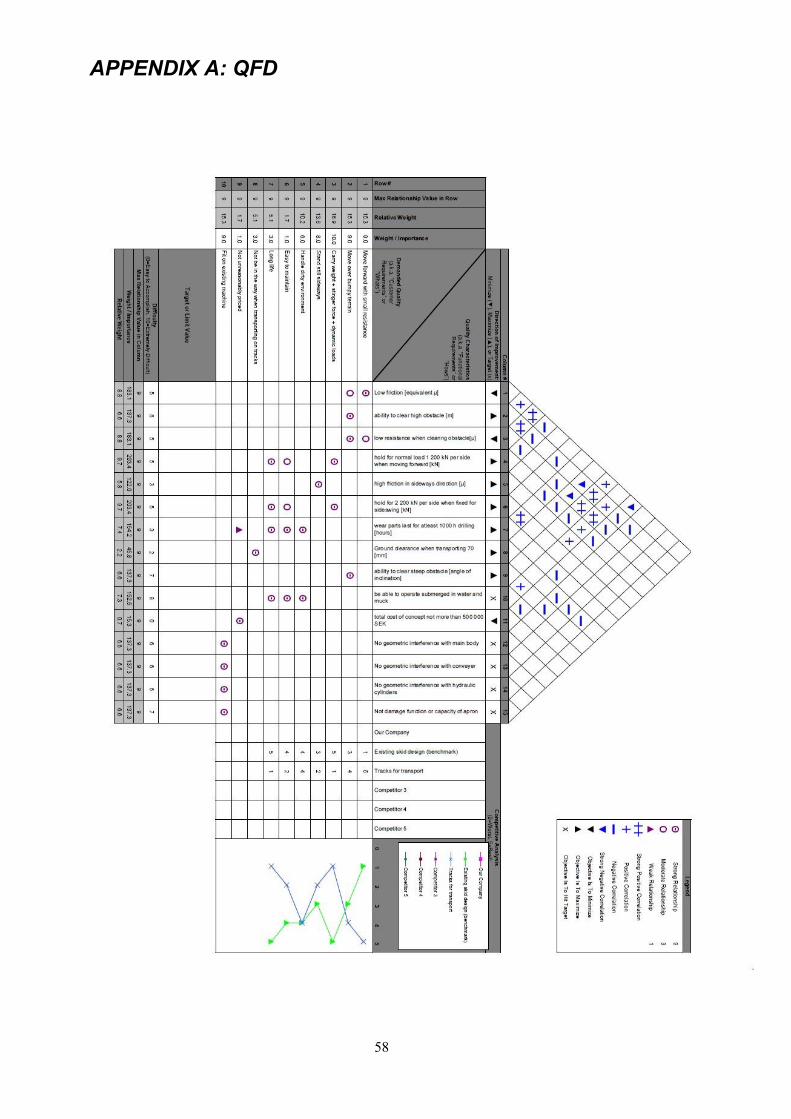
Requirements was processed and worked out with the help of QFD (see Appendix A). This is a good
process for understanding what the customer wants, developing specifications or goals for the product,
understand how the specifications measure the customers desires, determining how well the competition
meets the goals and developing measurable targets to work towards.
Figure 6. Overview of QFD
When the customer requirements had been processed to engineering requirements the supervisors at Svea
Teknik and the customer Atlas Copco revised them before setting final requirements.
When concepts was generated and selected by the customer, further development started. The concepts
was modeled in CAD and the structural design was evaluated in the FEA software ANSYS and
Mechanica. The design process was of the iterative kind where different applications are evaluated and
refined over and over again until the design was finished.

15
16
2 FRAME OF REFERENCE
This chapter presents background information that could be useful to understand the project and the Reef
Miner
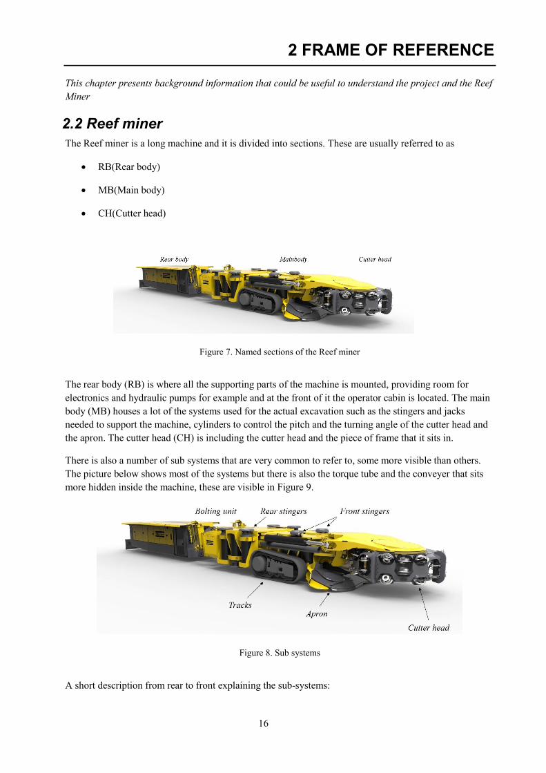
2.2 Reef miner
The Reef miner is a long machine and it is divided into sections. These are usually referred to as
RB(Rear body)
MB(Main body)
CH(Cutter head)
Figure 7. Named sections of the Reef miner
The rear body (RB) is where all the supporting parts of the machine is mounted, providing room for
electronics and hydraulic pumps for example and at the front of it the operator cabin is located. The main
body (MB) houses a lot of the systems used for the actual excavation such as the stingers and jacks
needed to support the machine, cylinders to control the pitch and the turning angle of the cutter head and
the apron. The cutter head (CH) is including the cutter head and the piece of frame that it sits in.
There is also a number of sub systems that are very common to refer to, some more visible than others.
The picture below shows most of the systems but there is also the torque tube and the conveyer that sits
more hidden inside the machine, these are visible in Figure 9.
Figure 8. Sub systems
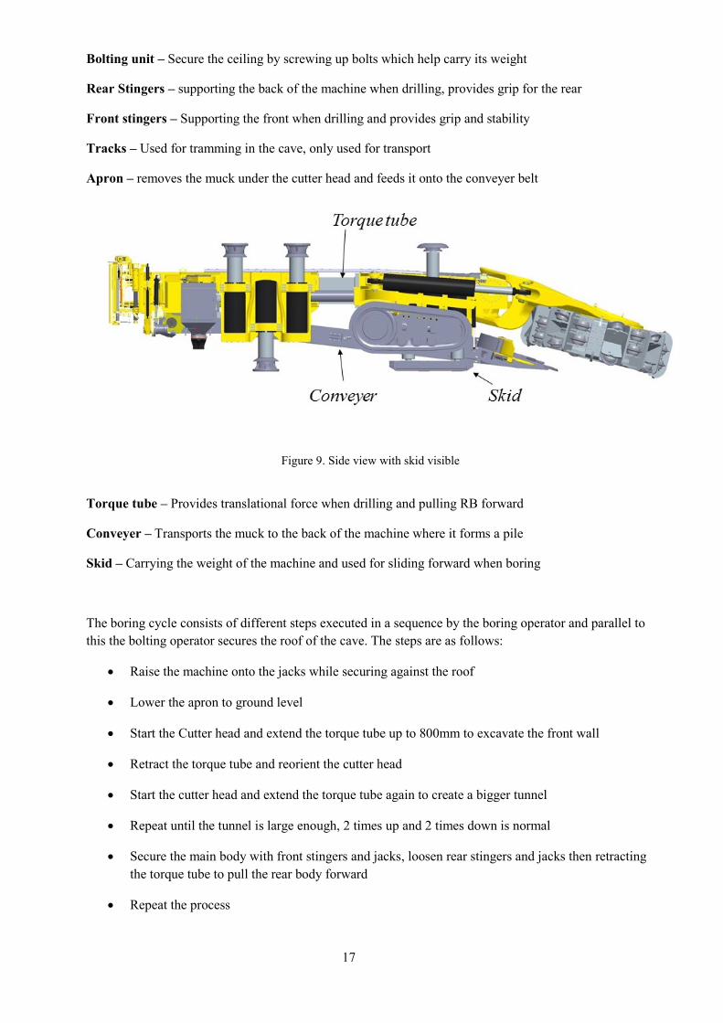
A short description from rear to front explaining the sub-systems:
17
Bolting unit – Secure the ceiling by screwing up bolts which help carry its weight
Rear Stingers – supporting the back of the machine when drilling, provides grip for the rear
Front stingers – Supporting the front when drilling and provides grip and stability
Tracks – Used for tramming in the cave, only used for transport
Apron – removes the muck under the cutter head and feeds it onto the conveyer belt
Figure 9. Side view with skid visible
Torque tube – Provides translational force when drilling and pulling RB forward
Conveyer – Transports the muck to the back of the machine where it forms a pile
Skid – Carrying the weight of the machine and used for sliding forward when boring
The boring cycle consists of different steps executed in a sequence by the boring operator and parallel to
this the bolting operator secures the roof of the cave. The steps are as follows:
Raise the machine onto the jacks while securing against the roof
Lower the apron to ground level
Start the Cutter head and extend the torque tube up to 800mm to excavate the front wall
Retract the torque tube and reorient the cutter head
Start the cutter head and extend the torque tube again to create a bigger tunnel
Repeat until the tunnel is large enough, 2 times up and 2 times down is normal
Secure the main body with front stingers and jacks, loosen rear stingers and jacks then retracting
the torque tube to pull the rear body forward
Repeat the process
18
The machine also has an alternative boring method which is done in almost the same way but instead
of retracting and reorienting the cutter head the machine presses harder onto the grippers and jacks
and swings the cutter head side-ways in the wall creating a bigger hole, the CH is the retracted and
lowered before doing the same procedure again at a lower height. This creates higher loads in the
jacks and stingers as well as more side loads.
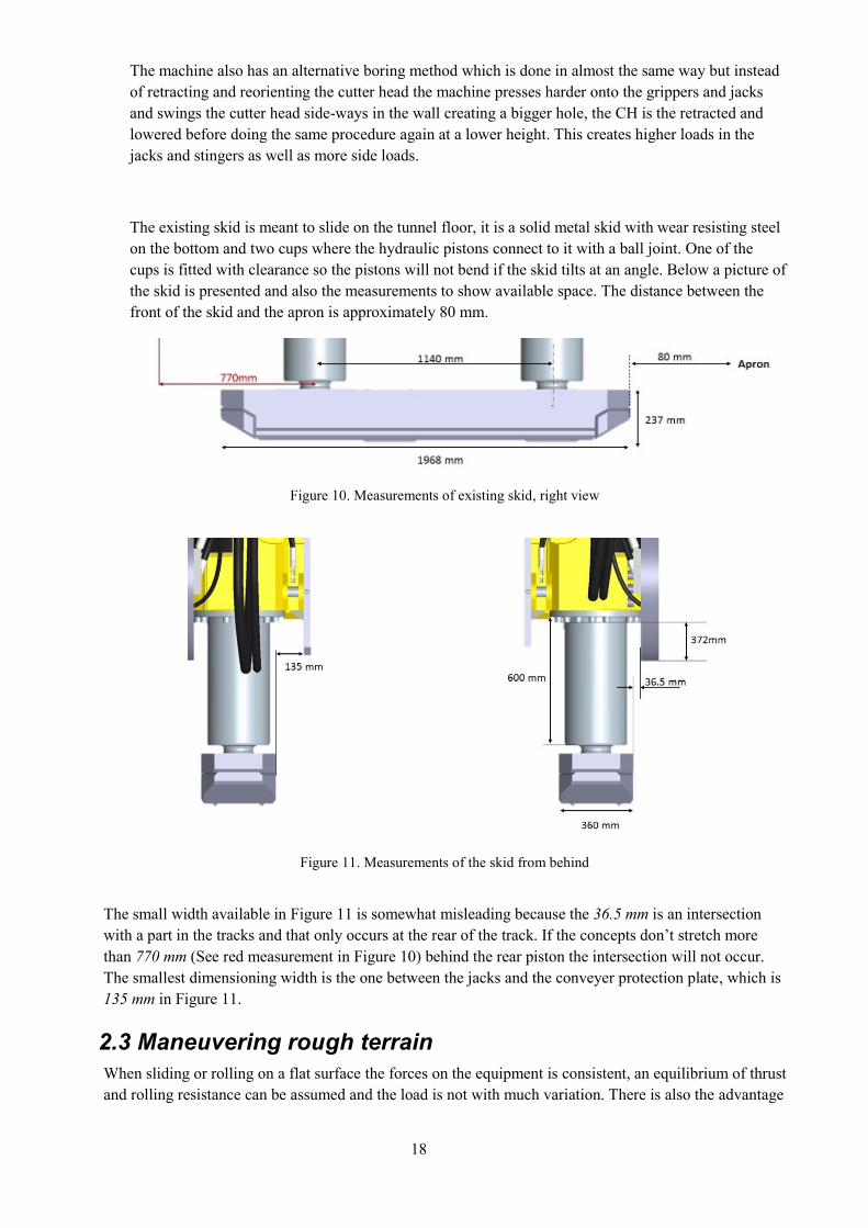
The existing skid is meant to slide on the tunnel floor, it is a solid metal skid with wear resisting steel
on the bottom and two cups where the hydraulic pistons connect to it with a ball joint. One of the
cups is fitted with clearance so the pistons will not bend if the skid tilts at an angle. Below a picture of
the skid is presented and also the measurements to show available space. The distance between the
front of the skid and the apron is approximately 80 mm.
Figure 10. Measurements of existing skid, right view
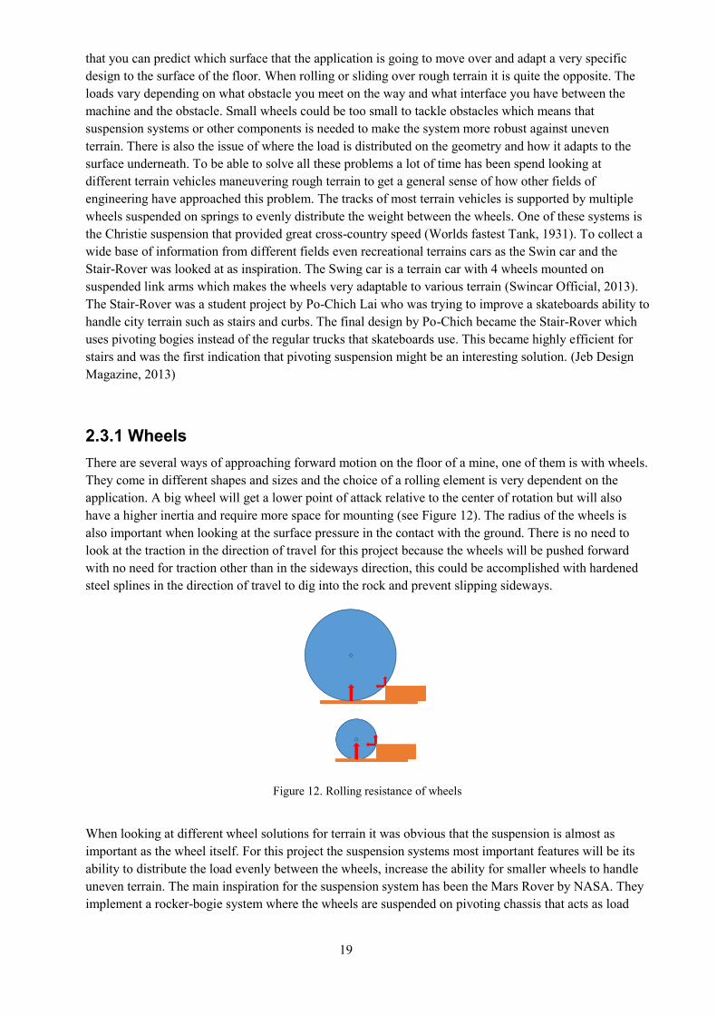
Figure 11. Measurements of the skid from behind
The small width available in Figure 11 is somewhat misleading because the 36.5 mm is an intersection
with a part in the tracks and that only occurs at the rear of the track. If the concepts don’t stretch more
than 770 mm (See red measurement in Figure 10) behind the rear piston the intersection will not occur.
The smallest dimensioning width is the one between the jacks and the conveyer protection plate, which is
135 mm in Figure 11.
2.3 Maneuvering rough terrain
When sliding or rolling on a flat surface the forces on the equipment is consistent, an equilibrium of thrust
and rolling resistance can be assumed and the load is not with much variation. There is also the advantage
19
that you can predict which surface that the application is going to move over and adapt a very specific
design to the surface of the floor. When rolling or sliding over rough terrain it is quite the opposite. The
loads vary depending on what obstacle you meet on the way and what interface you have between the
machine and the obstacle. Small wheels could be too small to tackle obstacles which means that
suspension systems or other components is needed to make the system more robust against uneven
terrain. There is also the issue of where the load is distributed on the geometry and how it adapts to the
surface underneath. To be able to solve all these problems a lot of time has been spend looking at
different terrain vehicles maneuvering rough terrain to get a general sense of how other fields of
engineering have approached this problem. The tracks of most terrain vehicles is supported by multiple
wheels suspended on springs to evenly distribute the weight between the wheels. One of these systems is
the Christie suspension that provided great cross-country speed (Worlds fastest Tank, 1931). To collect a
wide base of information from different fields even recreational terrains cars as the Swin car and the
Stair-Rover was looked at as inspiration. The Swing car is a terrain car with 4 wheels mounted on
suspended link arms which makes the wheels very adaptable to various terrain (Swincar Official, 2013).
The Stair-Rover was a student project by Po-Chich Lai who was trying to improve a skateboards ability to
handle city terrain such as stairs and curbs. The final design by Po-Chich became the Stair-Rover which
uses pivoting bogies instead of the regular trucks that skateboards use. This became highly efficient for
stairs and was the first indication that pivoting suspension might be an interesting solution. (Jeb Design
Magazine, 2013)
2.3.1 Wheels
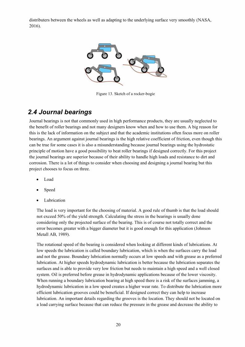
There are several ways of approaching forward motion on the floor of a mine, one of them is with wheels.
They come in different shapes and sizes and the choice of a rolling element is very dependent on the
application. A big wheel will get a lower point of attack relative to the center of rotation but will also
have a higher inertia and require more space for mounting (see Figure 12). The radius of the wheels is
also important when looking at the surface pressure in the contact with the ground. There is no need to
look at the traction in the direction of travel for this project because the wheels will be pushed forward
with no need for traction other than in the sideways direction, this could be accomplished with hardened
steel splines in the direction of travel to dig into the rock and prevent slipping sideways.
Figure 12. Rolling resistance of wheels
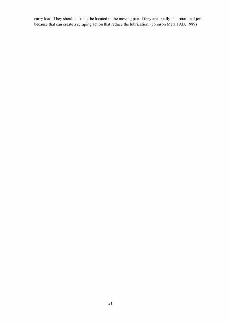
When looking at different wheel solutions for terrain it was obvious that the suspension is almost as
important as the wheel itself. For this project the suspension systems most important features will be its
ability to distribute the load evenly between the wheels, increase the ability for smaller wheels to handle
uneven terrain. The main inspiration for the suspension system has been the Mars Rover by NASA. They
implement a rocker-bogie system where the wheels are suspended on pivoting chassis that acts as load
20
distributers between the wheels as well as adapting to the underlying surface very smoothly (NASA,
2016).
Figure 13. Sketch of a rocker-bogie
2.4 Journal bearings
Journal bearings is not that commonly used in high performance products, they are usually neglected to
the benefit of roller bearings and not many designers know when and how to use them. A big reason for
this is the lack of information on the subject and that the academic institutions often focus more on roller
bearings. An argument against journal bearings is the high relative coefficient of friction, even though this
can be true for some cases it is also a misunderstanding because journal bearings using the hydrostatic
principle of motion have a good possibility to beat roller bearings if designed correctly. For this project
the journal bearings are superior because of their ability to handle high loads and resistance to dirt and
corrosion. There is a lot of things to consider when choosing and designing a journal bearing but this
project chooses to focus on three.
Load
Speed
Lubrication
The load is very important for the choosing of material. A good rule of thumb is that the load should
not exceed 50% of the yield strength. Calculating the stress in the bearings is usually done
considering only the projected surface of the bearing. This is of course not totally correct and the
error becomes greater with a bigger diameter but it is good enough for this application (Johnson
Metall AB, 1989).
The rotational speed of the bearing is considered when looking at different kinds of lubrications. At
low speeds the lubrication is called boundary lubrication, which is when the surfaces carry the load
and not the grease. Boundary lubrication normally occurs at low speeds and with grease as a preferred
lubrication. At higher speeds hydrodynamic lubrication is better because the lubrication separates the
surfaces and is able to provide very low friction but needs to maintain a high speed and a well closed
system. Oil is preferred before grease in hydrodynamic applications because of the lower viscosity.
When running a boundary lubrication bearing at high speed there is a risk of the surfaces jamming, a
hydrodynamic lubrication in a low speed creates a higher wear rate. To distribute the lubrication more
efficient lubrication grooves could be beneficial. If designed correct they can help to increase
lubrication. An important details regarding the grooves is the location. They should not be located on
a load carrying surface because that can reduce the pressure in the grease and decrease the ability to
21
carry load. They should also not be located in the moving part if they are axially in a rotational joint
because that can create a scraping action that reduce the lubrication. (Johnson Metall AB, 1989)

22
23
3 METHODOLOGY AND RESULTS
This chapter covers the design process of the concepts, requirements, concept generation, selecting
concepts, further development and analysis
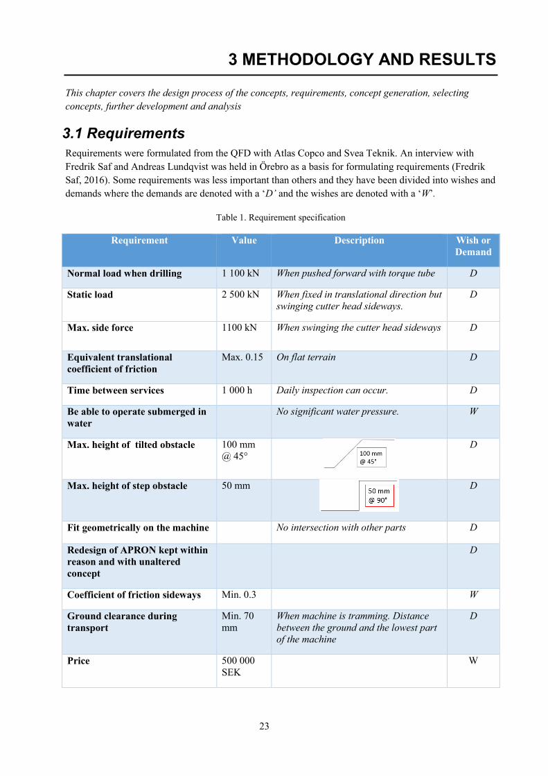
3.1 Requirements
Requirements were formulated from the QFD with Atlas Copco and Svea Teknik. An interview with
Fredrik Saf and Andreas Lundqvist was held in Örebro as a basis for formulating requirements (Fredrik
Saf, 2016). Some requirements was less important than others and they have been divided into wishes and
demands where the demands are denoted with a ‘D’ and the wishes are denoted with a ‘W’.
Table 1. Requirement specification
Requirement Value Description Wish or
Demand
Normal load when drilling 1 100 kN When pushed forward with torque tube D
Static load 2 500 kN When fixed in translational direction but
swinging cutter head sideways.
D
Max. side force 1100 kN When swinging the cutter head sideways D
Equivalent translational
coefficient of friction
Max. 0.15 On flat terrain D
Time between services 1 000 h Daily inspection can occur. D
Be able to operate submerged in
water
No significant water pressure. W
Max. height of tilted obstacle 100 mm
@ 45°
D
Max. height of step obstacle 50 mm
D
Fit geometrically on the machine No intersection with other parts D
Redesign of APRON kept within
reason and with unaltered
concept
D
Coefficient of friction sideways Min. 0.3 W
Ground clearance during
transport
Min. 70
mm
When machine is tramming. Distance
between the ground and the lowest part
of the machine
D
Price 500 000
SEK
W
24
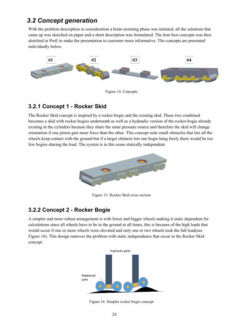
3.2 Concept generation
With the problem description in consideration a brain storming phase was initiated, all the solutions that
came up was sketched on paper and a short description was formulated. The four best concepts was then
sketched in ProE to make the presentation to customer more informative. The concepts are presented
individually below.
Figure 14. Concepts
3.2.1 Concept 1 - Rocker Skid
The Rocker Skid concept is inspired by a rocker-bogie and the existing skid. These two combined
becomes a skid with rocker-bogies underneath as well as a hydraulic version of the rocker-bogie already
existing in the cylinders because they share the same pressure source and therefore the skid will change
orientation if one piston gets more force than the other. This concept suits small obstacles that lets all the
wheels keep contact with the ground but if a larger obstacle lets one bogie hang freely there would be too
few bogies sharing the load. The system is in this sense statically independent.
Figure 15. Rocker Skid cross section
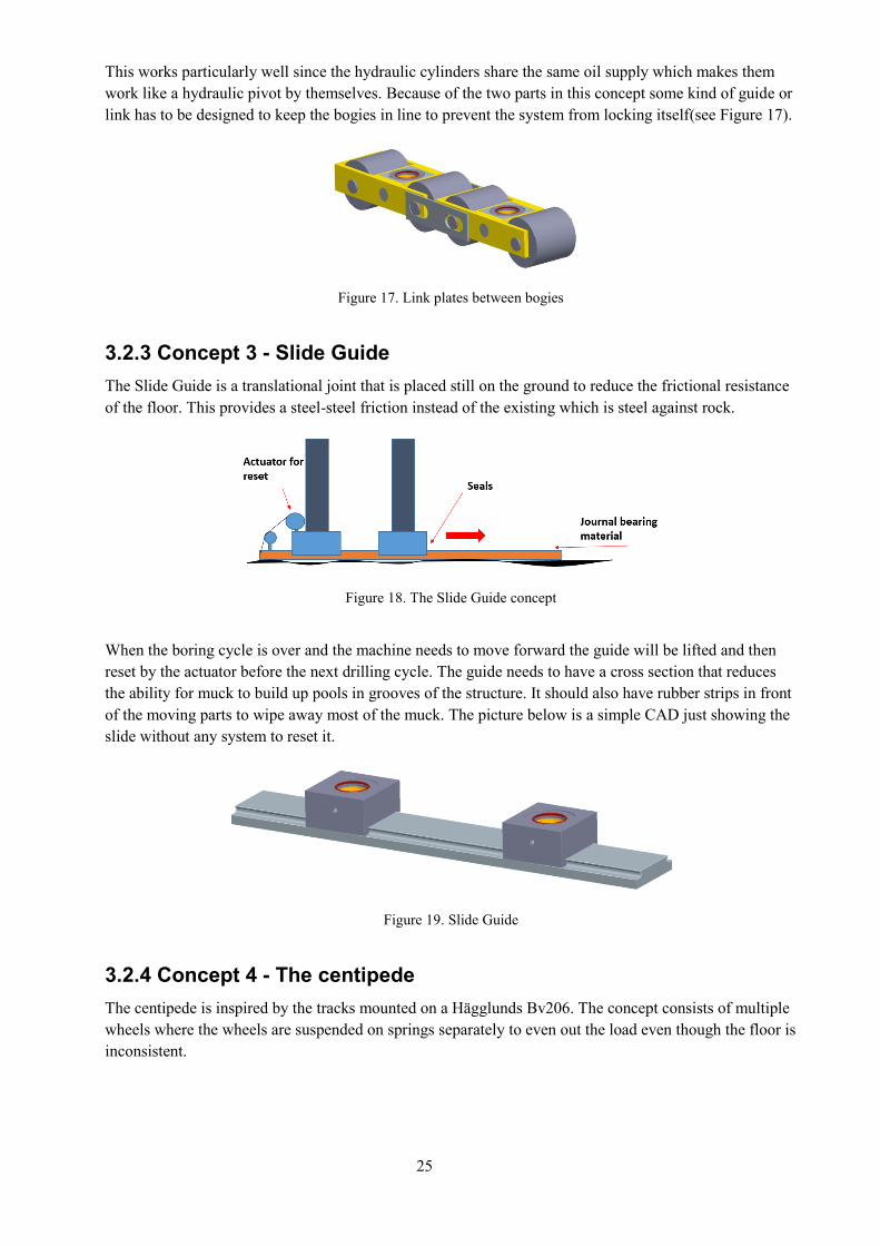
3.2.2 Concept 2 - Rocker Bogie
A simpler and more robust arrangement is with fewer and bigger wheels making it static dependent for
calculations since all wheels have to be in the ground at all times, this is because of the high loads that
would occur if one or more wheels were elevated and only one or two wheels took the full load(see
Figure 16). This design removes the problem with static independence that occur in the Rocker Skid
concept.
Figure 16. Simpler rocker bogie concept
25
This works particularly well since the hydraulic cylinders share the same oil supply which makes them
work like a hydraulic pivot by themselves. Because of the two parts in this concept some kind of guide or
link has to be designed to keep the bogies in line to prevent the system from locking itself(see Figure 17).
Figure 17. Link plates between bogies
3.2.3 Concept 3 - Slide Guide
The Slide Guide is a translational joint that is placed still on the ground to reduce the frictional resistance
of the floor. This provides a steel-steel friction instead of the existing which is steel against rock.
Figure 18. The Slide Guide concept
When the boring cycle is over and the machine needs to move forward the guide will be lifted and then
reset by the actuator before the next drilling cycle. The guide needs to have a cross section that reduces
the ability for muck to build up pools in grooves of the structure. It should also have rubber strips in front
of the moving parts to wipe away most of the muck. The picture below is a simple CAD just showing the
slide without any system to reset it.
Figure 19. Slide Guide
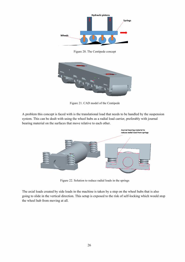
3.2.4 Concept 4 - The centipede
The centipede is inspired by the tracks mounted on a Hägglunds Bv206. The concept consists of multiple
wheels where the wheels are suspended on springs separately to even out the load even though the floor is
inconsistent.
26
Figure 20. The Centipede concept
Figure 21. CAD model of the Centipede
A problem this concept is faced with is the translational load that needs to be handled by the suspension
system. This can be dealt with using the wheel hubs as a radial load carrier, preferably with journal
bearing material on the surfaces that move relative to each other.
Figure 22. Solution to reduce radial loads in the springs
The axial loads created by side loads in the machine is taken by a step on the wheel hubs that is also
going to slide in the vertical direction. This setup is exposed to the risk of self-locking which would stop
the wheel hub from moving at all.
27
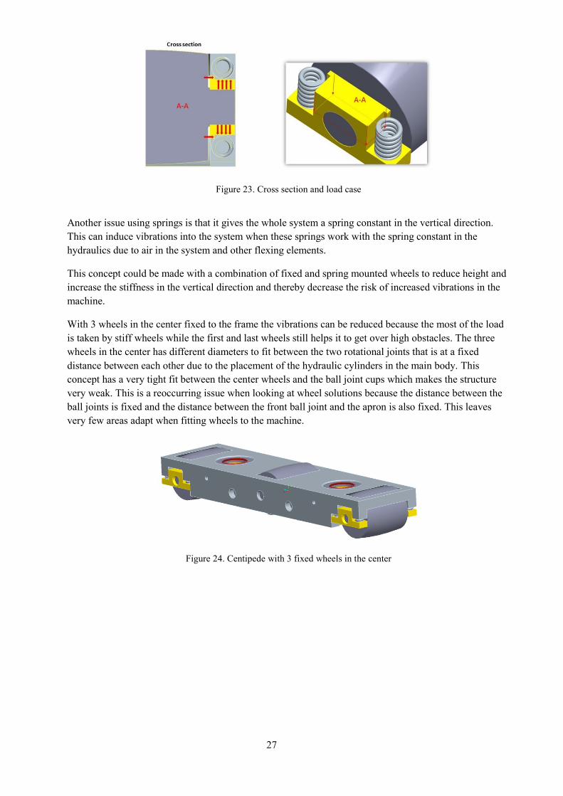
Figure 23. Cross section and load case
Another issue using springs is that it gives the whole system a spring constant in the vertical direction.
This can induce vibrations into the system when these springs work with the spring constant in the
hydraulics due to air in the system and other flexing elements.
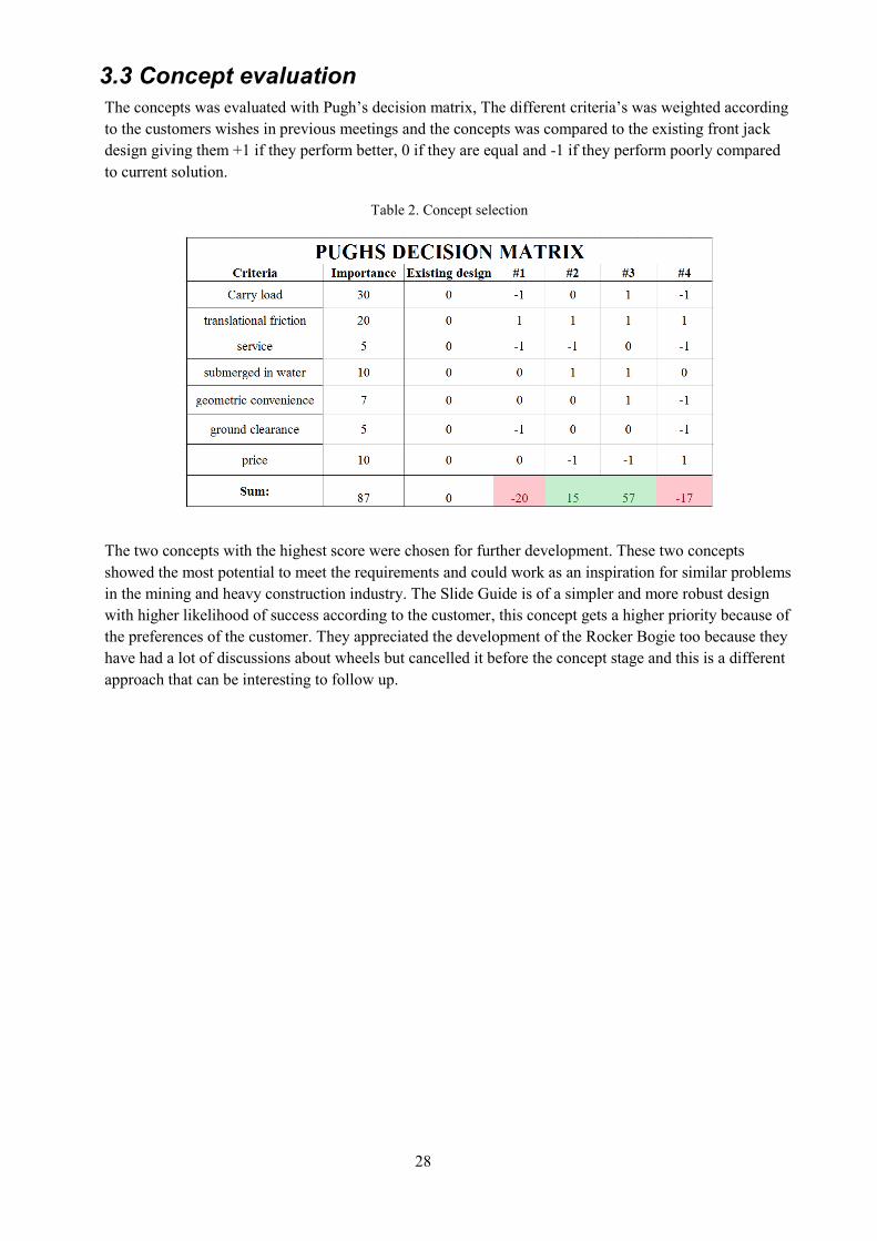
This concept could be made with a combination of fixed and spring mounted wheels to reduce height and
increase the stiffness in the vertical direction and thereby decrease the risk of increased vibrations in the
machine.
With 3 wheels in the center fixed to the frame the vibrations can be reduced because the most of the load
is taken by stiff wheels while the first and last wheels still helps it to get over high obstacles. The three
wheels in the center has different diameters to fit between the two rotational joints that is at a fixed
distance between each other due to the placement of the hydraulic cylinders in the main body. This
concept has a very tight fit between the center wheels and the ball joint cups which makes the structure
very weak. This is a reoccurring issue when looking at wheel solutions because the distance between the
ball joints is fixed and the distance between the front ball joint and the apron is also fixed. This leaves
very few areas adapt when fitting wheels to the machine.
Figure 24. Centipede with 3 fixed wheels in the center
28
3.3 Concept evaluation
The concepts was evaluated with Pugh’s decision matrix, The different criteria’s was weighted according
to the customers wishes in previous meetings and the concepts was compared to the existing front jack
design giving them +1 if they perform better, 0 if they are equal and -1 if they perform poorly compared
to current solution.
Table 2. Concept selection
The two concepts with the highest score were chosen for further development. These two concepts
showed the most potential to meet the requirements and could work as an inspiration for similar problems
in the mining and heavy construction industry. The Slide Guide is of a simpler and more robust design
with higher likelihood of success according to the customer, this concept gets a higher priority because of
the preferences of the customer. They appreciated the development of the Rocker Bogie too because they
have had a lot of discussions about wheels but cancelled it before the concept stage and this is a different
approach that can be interesting to follow up.
29
3.4 Rocker Bogie
This section describes the Rocker Bogie concept in detail, working principles and analysis
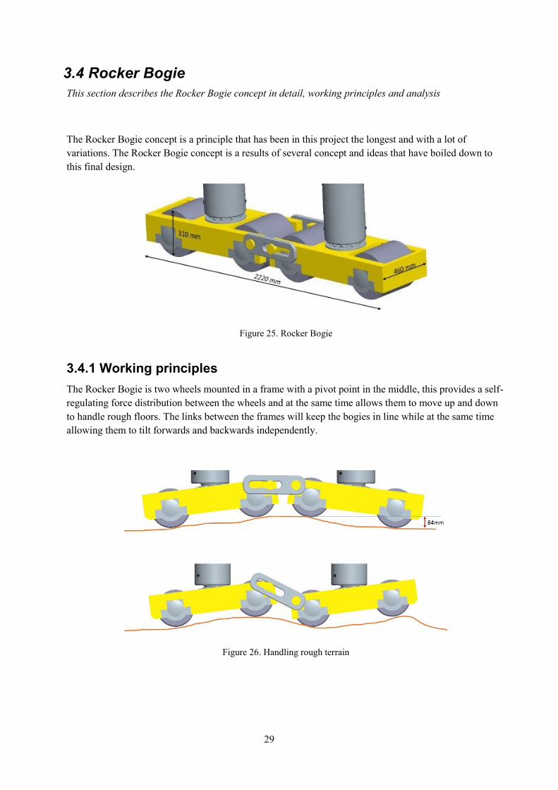
The Rocker Bogie concept is a principle that has been in this project the longest and with a lot of
variations. The Rocker Bogie concept is a results of several concept and ideas that have boiled down to
this final design.
Figure 25. Rocker Bogie
3.4.1 Working principles
The Rocker Bogie is two wheels mounted in a frame with a pivot point in the middle, this provides a self-
regulating force distribution between the wheels and at the same time allows them to move up and down
to handle rough floors. The links between the frames will keep the bogies in line while at the same time
allowing them to tilt forwards and backwards independently.
Figure 26. Handling rough terrain
30
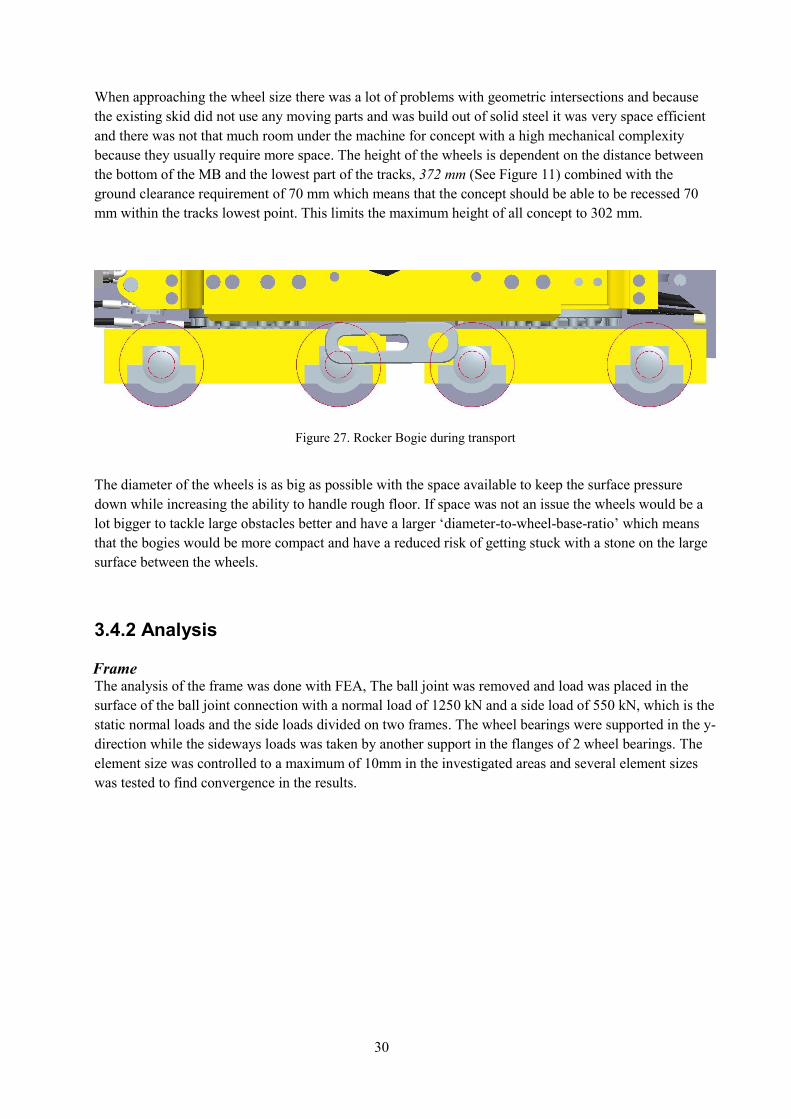
When approaching the wheel size there was a lot of problems with geometric intersections and because
the existing skid did not use any moving parts and was build out of solid steel it was very space efficient
and there was not that much room under the machine for concept with a high mechanical complexity
because they usually require more space. The height of the wheels is dependent on the distance between
the bottom of the MB and the lowest part of the tracks, 372 mm (See Figure 11) combined with the
ground clearance requirement of 70 mm which means that the concept should be able to be recessed 70
mm within the tracks lowest point. This limits the maximum height of all concept to 302 mm.
Figure 27. Rocker Bogie during transport
The diameter of the wheels is as big as possible with the space available to keep the surface pressure
down while increasing the ability to handle rough floor. If space was not an issue the wheels would be a
lot bigger to tackle large obstacles better and have a larger ‘diameter-to-wheel-base-ratio’ which means
that the bogies would be more compact and have a reduced risk of getting stuck with a stone on the large
surface between the wheels.
3.4.2 Analysis
Frame The analysis of the frame was done with FEA, The ball joint was removed and load was placed in the
surface of the ball joint connection with a normal load of 1250 kN and a side load of 550 kN, which is the
static normal loads and the side loads divided on two frames. The wheel bearings were supported in the y-
direction while the sideways loads was taken by another support in the flanges of 2 wheel bearings. The
element size was controlled to a maximum of 10mm in the investigated areas and several element sizes
was tested to find convergence in the results.
31
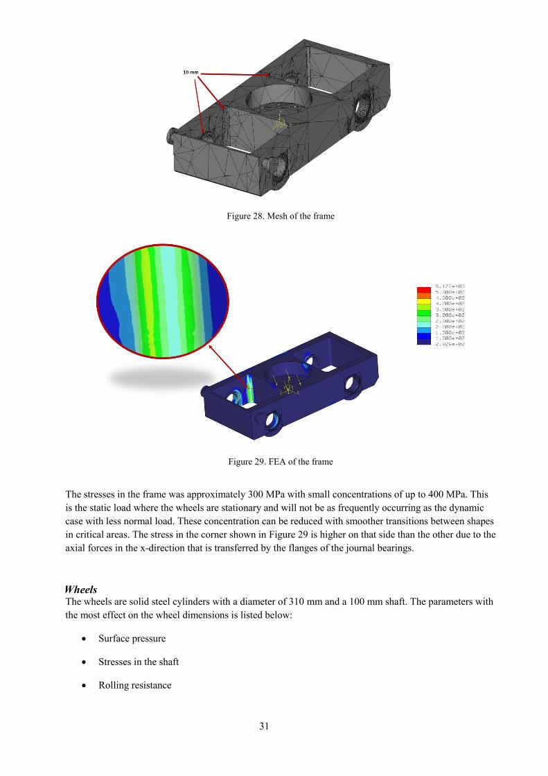
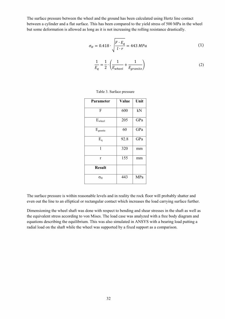
Figure 28. Mesh of the frame
Figure 29. FEA of the frame
The stresses in the frame was approximately 300 MPa with small concentrations of up to 400 MPa. This
is the static load where the wheels are stationary and will not be as frequently occurring as the dynamic
case with less normal load. These concentration can be reduced with smoother transitions between shapes
in critical areas. The stress in the corner shown in Figure 29 is higher on that side than the other due to the
axial forces in the x-direction that is transferred by the flanges of the journal bearings.
Wheels The wheels are solid steel cylinders with a diameter of 310 mm and a 100 mm shaft. The parameters with
the most effect on the wheel dimensions is listed below:
Surface pressure
Stresses in the shaft
Rolling resistance
32
The surface pressure between the wheel and the ground has been calculated using Hertz line contact
between a cylinder and a flat surface. This has been compared to the yield stress of 500 MPa in the wheel
but some deformation is allowed as long as it is not increasing the rolling resistance drastically.
𝜎𝐻 = 0.418 ∙ √𝐹 ∙ 𝐸𝑞𝑙 ∙ 𝑟
= 443 𝑀𝑃𝑎 (1)
1
𝐸𝑞=1
2∙ (
1
𝐸𝑤ℎ𝑒𝑒𝑙+
1
𝐸𝑔𝑟𝑎𝑛𝑖𝑡𝑒) (2)
Table 3. Surface pressure
Parameter Value Unit
F 600 kN
Ewheel 205 GPa
Egranite 60 GPa
Eq 92.8 GPa
l 320 mm
r 155 mm
Result
σH 443 MPa
The surface pressure is within reasonable levels and in reality the rock floor will probably shatter and
even out the line to an elliptical or rectangular contact which increases the load carrying surface further.
Dimensioning the wheel shaft was done with respect to bending and shear stresses in the shaft as well as
the equivalent stress according to von Mises. The load case was analyzed with a free body diagram and
equations describing the equilibrium. This was also simulated in ANSYS with a bearing load putting a
radial load on the shaft while the wheel was supported by a fixed support as a comparison.
33
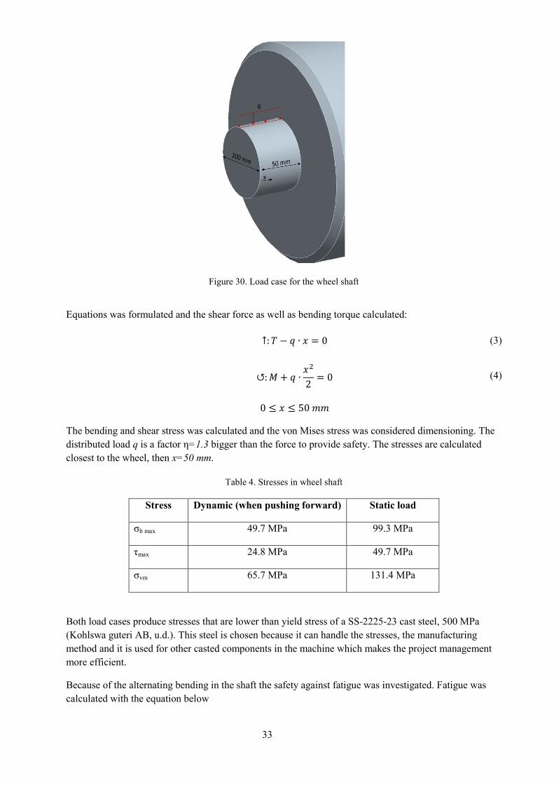
Figure 30. Load case for the wheel shaft
Equations was formulated and the shear force as well as bending torque calculated:
↑: 𝑇 − 𝑞 ∙ 𝑥 = 0 (3)
↺:𝑀 + 𝑞 ∙𝑥2
2= 0 (4)
0 ≤ 𝑥 ≤ 50 𝑚𝑚
The bending and shear stress was calculated and the von Mises stress was considered dimensioning. The
distributed load q is a factor η=1.3 bigger than the force to provide safety. The stresses are calculated
closest to the wheel, then x=50 mm.
Table 4. Stresses in wheel shaft
Stress Dynamic (when pushing forward) Static load
σb max 49.7 MPa 99.3 MPa
τmax 24.8 MPa 49.7 MPa
σvm 65.7 MPa 131.4 MPa
Both load cases produce stresses that are lower than yield stress of a SS-2225-23 cast steel, 500 MPa
(Kohlswa guteri AB, u.d.). This steel is chosen because it can handle the stresses, the manufacturing
method and it is used for other casted components in the machine which makes the project management
more efficient.
Because of the alternating bending in the shaft the safety against fatigue was investigated. Fatigue was
calculated with the equation below
34
𝑠 =𝜆 ∙ 𝛿 ∙ 𝜅 ∙ 𝜎𝐷
𝜑 ∙ [1 + 𝑞(𝐾𝑡 − 1)] ∙ 𝜎𝑛𝑜𝑚= 1.2 (5)
Table 5. Fatigue in wheel shaft
Parameter Value Unit Comments
λ 0.8 - Technological dependence of volume
δ 0.88 - Geometrical dependence of volume
κ 1 - Surface factor which depends on the surface roughness
σD 480 MPa Limit for fatigue in bended shafts
φ 2.5 - Factor depending on the shock in the motion
q 0.85 - Factor of sensitivity for the concentration radius
Kt 2.5 - Form factor of the concentration
σnom 49.7 MPa Nominal stress.
Results
s 1.2 - Safety against fatigue
The safety against fatigue is close to the recommendations of 1.2 < s < 3 for machine steel (Björk, 6th
edition). The factor of safety could be to low but since the break down would only effect productivity and
not risk human lives this can be investigated during testing. If a break down would set human lives at risk
the factor of safety would have to be increased.
The obstacle requirement was difficult to verify because of the small space available, if a bigger wheel
diameter was used it would have been simpler to verify that it meets the requirements. A small analysis
was made that calculated the amount of force needed from the torque tube to create a torque bigger than
the resisting torque from a stiff obstacle of 50 mm. The force needed to push the machine forward was
bigger than the force needed with the existing skid. In reality the obstacle would be made out of rock and
not totally stiff which means that the edge would break when the wheel pressed onto it and reduce its
height. This is why another assumption was made where the edge would break and form a stiff height of
30 mm that the wheel should then climb. This was more beneficial for the wheel and would let it pass the
obstacle requirement.
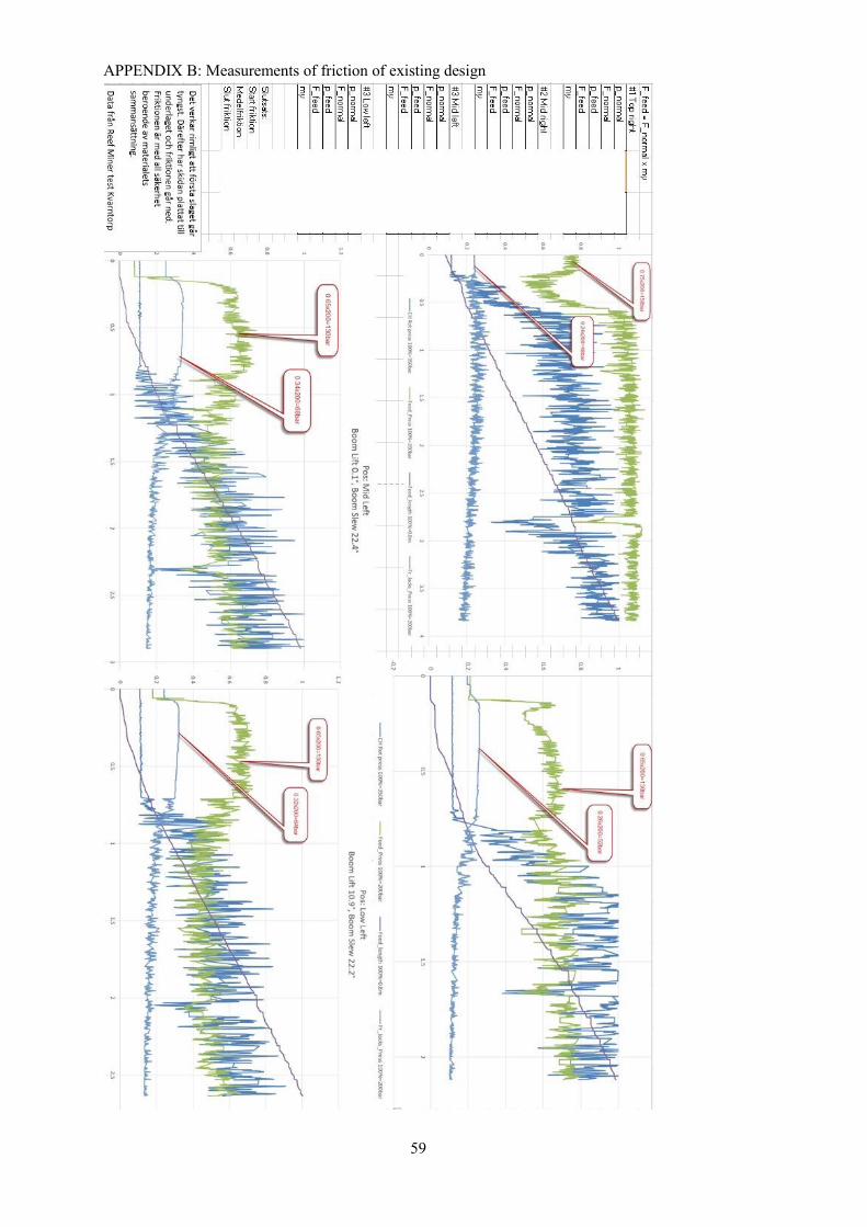
Bearings The journal bearings used are JF flange bearing made from JM1. It has been dimensioned considering
bearings pressure, velocity and pv-product. The forces in the bearings are the same as on the shaft. The
velocity was calculated with the wheel and shaft diameters and measurements from drilling where the
speed of the torque tube was plotted (See Appendix B). Equivalent friction, µeq was calculated by
dividing the shaft radius with the wheel radius.
35
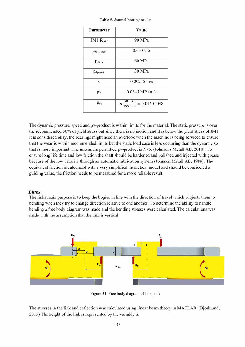
Table 6. Journal bearing results
Parameter Value
JM1 Rp0.2 90 MPa
µJM1-steel 0.05-0.15
pstatic 60 MPa
pdynamic 30 MPa
v 0.00215 m/s
pv 0.0645 MPa m/s
µeq 𝜇50 𝑚𝑚
155 𝑚𝑚= 0.016-0.048
The dynamic pressure, speed and pv-product is within limits for the material. The static pressure is over
the recommended 50% of yield stress but since there is no motion and it is below the yield stress of JM1
it is considered okay, the bearings might need an overlook when the machine is being serviced to ensure
that the wear is within recommended limits but the static load case is less occurring than the dynamic so
that is more important. The maximum permitted pv-product is 1.75. (Johnsons Metall AB, 2010). To
ensure long life time and low friction the shaft should be hardened and polished and injected with grease
because of the low velocity through an automatic lubrication system (Johnson Metall AB, 1989). The
equivalent friction is calculated with a very simplified theoretical model and should be considered a
guiding value, the friction needs to be measured for a more reliable result.
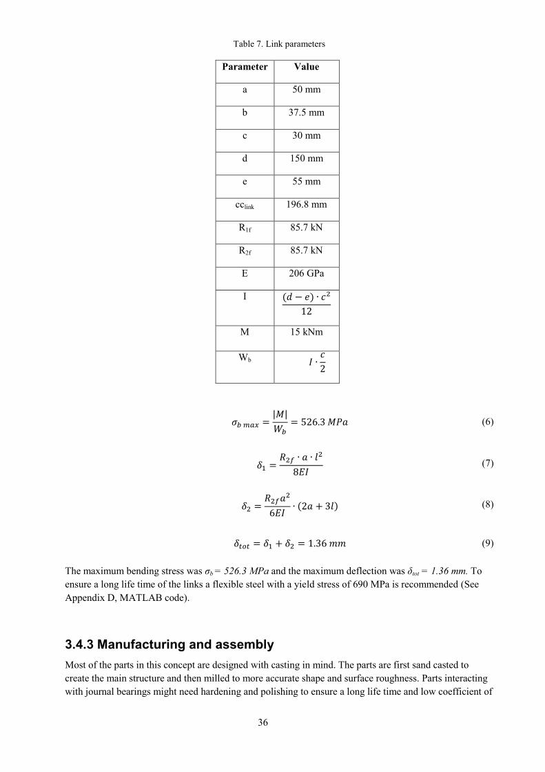
Links The links main purpose is to keep the bogies in line with the direction of travel which subjects them to
bending when they try to change direction relative to one another. To determine the ability to handle
bending a free body diagram was made and the bending stresses were calculated. The calculations was
made with the assumption that the link is vertical.
Figure 31. Free body diagram of link plate
The stresses in the link and deflection was calculated using linear beam theory in MATLAB. (Björklund,
2015) The height of the link is represented by the variable d.
36
Table 7. Link parameters
Parameter Value
a 50 mm
b 37.5 mm
c 30 mm
d 150 mm
e 55 mm
cclink 196.8 mm
R1f 85.7 kN
R2f 85.7 kN
E 206 GPa
I (𝑑 − 𝑒) ∙ 𝑐2
12
M 15 kNm
Wb 𝐼 ∙𝑐
2
𝜎𝑏 𝑚𝑎𝑥 =|𝑀|
𝑊𝑏= 526.3 𝑀𝑃𝑎 (6)
𝛿1 =𝑅2𝑓 ∙ 𝑎 ∙ 𝑙
2
8𝐸𝐼 (7)
𝛿2 =𝑅2𝑓𝑎
2
6𝐸𝐼∙ (2𝑎 + 3𝑙) (8)
𝛿𝑡𝑜𝑡 = 𝛿1 + 𝛿2 = 1.36 𝑚𝑚 (9)
The maximum bending stress was σb = 526.3 MPa and the maximum deflection was δtot = 1.36 mm. To
ensure a long life time of the links a flexible steel with a yield stress of 690 MPa is recommended (See
Appendix D, MATLAB code).
3.4.3 Manufacturing and assembly
Most of the parts in this concept are designed with casting in mind. The parts are first sand casted to
create the main structure and then milled to more accurate shape and surface roughness. Parts interacting
with journal bearings might need hardening and polishing to ensure a long life time and low coefficient of
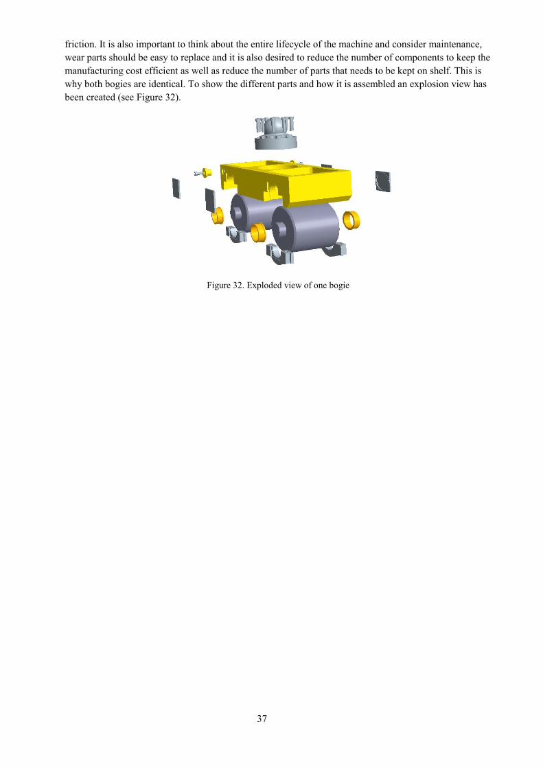
37
friction. It is also important to think about the entire lifecycle of the machine and consider maintenance,
wear parts should be easy to replace and it is also desired to reduce the number of components to keep the
manufacturing cost efficient as well as reduce the number of parts that needs to be kept on shelf. This is
why both bogies are identical. To show the different parts and how it is assembled an explosion view has
been created (see Figure 32).
Figure 32. Exploded view of one bogie
38
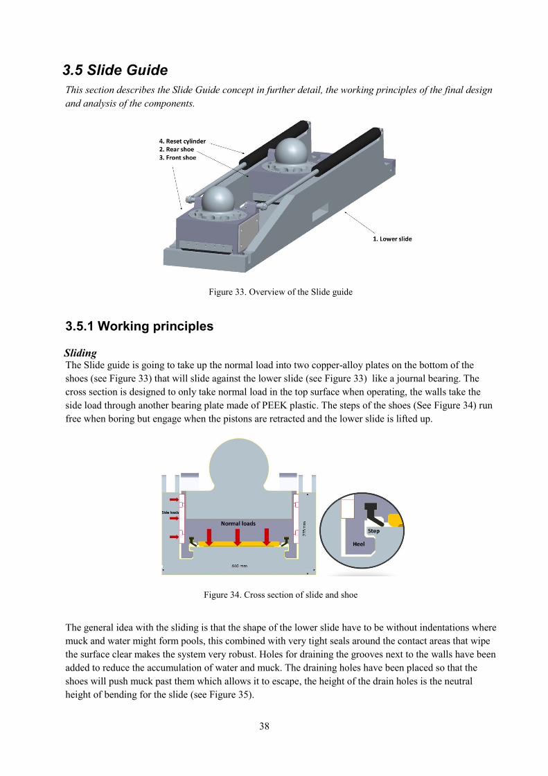
3.5 Slide Guide
This section describes the Slide Guide concept in further detail, the working principles of the final design
and analysis of the components.
Figure 33. Overview of the Slide guide
3.5.1 Working principles
Sliding The Slide guide is going to take up the normal load into two copper-alloy plates on the bottom of the
shoes (see Figure 33) that will slide against the lower slide (see Figure 33) like a journal bearing. The
cross section is designed to only take normal load in the top surface when operating, the walls take the
side load through another bearing plate made of PEEK plastic. The steps of the shoes (See Figure 34) run
free when boring but engage when the pistons are retracted and the lower slide is lifted up.
Figure 34. Cross section of slide and shoe
The general idea with the sliding is that the shape of the lower slide have to be without indentations where
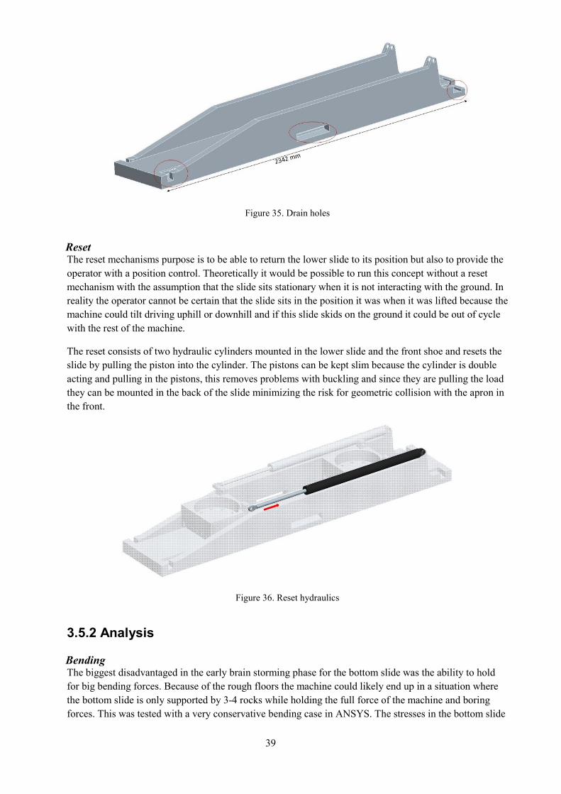
muck and water might form pools, this combined with very tight seals around the contact areas that wipe
the surface clear makes the system very robust. Holes for draining the grooves next to the walls have been
added to reduce the accumulation of water and muck. The draining holes have been placed so that the
shoes will push muck past them which allows it to escape, the height of the drain holes is the neutral
height of bending for the slide (see Figure 35).
39
Figure 35. Drain holes
Reset The reset mechanisms purpose is to be able to return the lower slide to its position but also to provide the
operator with a position control. Theoretically it would be possible to run this concept without a reset
mechanism with the assumption that the slide sits stationary when it is not interacting with the ground. In
reality the operator cannot be certain that the slide sits in the position it was when it was lifted because the
machine could tilt driving uphill or downhill and if this slide skids on the ground it could be out of cycle
with the rest of the machine.
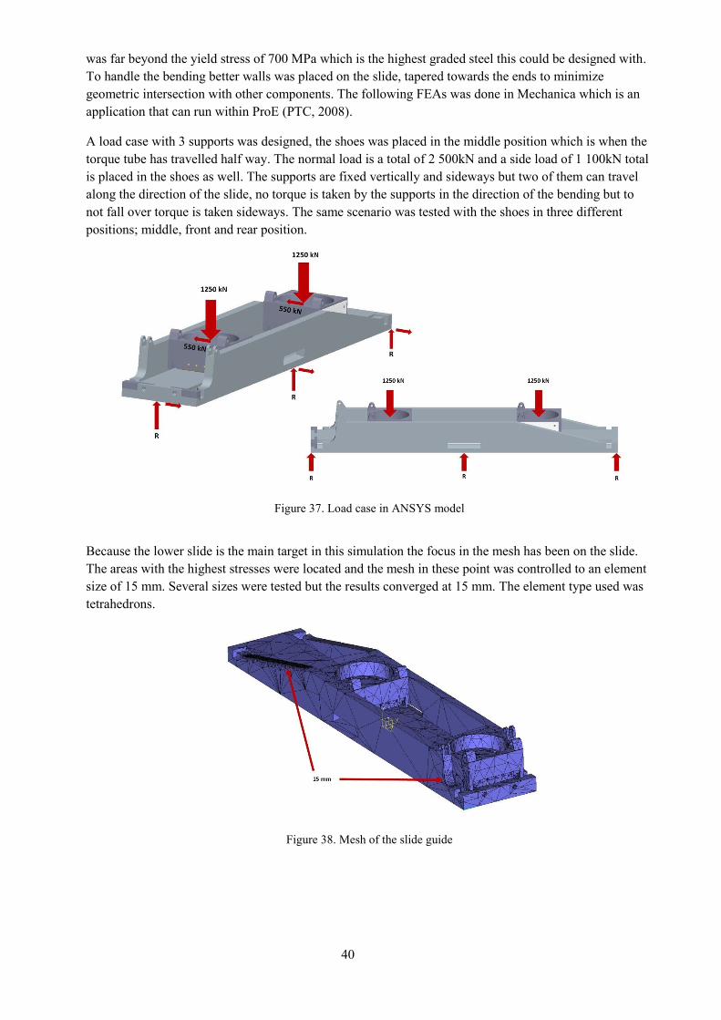
The reset consists of two hydraulic cylinders mounted in the lower slide and the front shoe and resets the
slide by pulling the piston into the cylinder. The pistons can be kept slim because the cylinder is double
acting and pulling in the pistons, this removes problems with buckling and since they are pulling the load
they can be mounted in the back of the slide minimizing the risk for geometric collision with the apron in
the front.
Figure 36. Reset hydraulics
3.5.2 Analysis
Bending The biggest disadvantaged in the early brain storming phase for the bottom slide was the ability to hold
for big bending forces. Because of the rough floors the machine could likely end up in a situation where
the bottom slide is only supported by 3-4 rocks while holding the full force of the machine and boring
forces. This was tested with a very conservative bending case in ANSYS. The stresses in the bottom slide
40
was far beyond the yield stress of 700 MPa which is the highest graded steel this could be designed with.
To handle the bending better walls was placed on the slide, tapered towards the ends to minimize
geometric intersection with other components. The following FEAs was done in Mechanica which is an
application that can run within ProE (PTC, 2008).
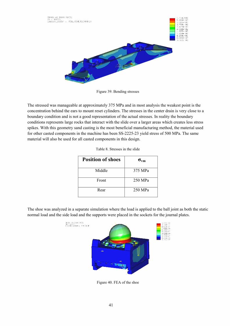
A load case with 3 supports was designed, the shoes was placed in the middle position which is when the
torque tube has travelled half way. The normal load is a total of 2 500kN and a side load of 1 100kN total
is placed in the shoes as well. The supports are fixed vertically and sideways but two of them can travel
along the direction of the slide, no torque is taken by the supports in the direction of the bending but to
not fall over torque is taken sideways. The same scenario was tested with the shoes in three different
positions; middle, front and rear position.
Figure 37. Load case in ANSYS model
Because the lower slide is the main target in this simulation the focus in the mesh has been on the slide.
The areas with the highest stresses were located and the mesh in these point was controlled to an element
size of 15 mm. Several sizes were tested but the results converged at 15 mm. The element type used was
tetrahedrons.
Figure 38. Mesh of the slide guide
41
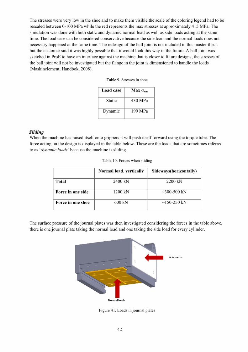
Figure 39. Bending stresses
The stressed was manageable at approximately 375 MPa and in most analysis the weakest point is the
concentration behind the ears to mount reset cylinders. The stresses in the center drain is very close to a
boundary condition and is not a good representation of the actual stresses. In reality the boundary
conditions represents large rocks that interact with the slide over a larger areas which creates less stress
spikes. With this geometry sand casting is the most beneficial manufacturing method, the material used
for other casted components in the machine has been SS-2225-23 yield stress of 500 MPa. The same
material will also be used for all casted components in this design.
Table 8. Stresses in the slide
Position of shoes σvm
Middle 375 MPa
Front 250 MPa
Rear 250 MPa
The shoe was analyzed in a separate simulation where the load is applied to the ball joint as both the static
normal load and the side load and the supports were placed in the sockets for the journal plates.
Figure 40. FEA of the shoe
42
The stresses were very low in the shoe and to make them visible the scale of the coloring legend had to be
rescaled between 0-100 MPa while the red represents the max stresses at approximately 415 MPa. The
simulation was done with both static and dynamic normal load as well as side loads acting at the same
time. The load case can be considered conservative because the side load and the normal loads does not
necessary happened at the same time. The redesign of the ball joint is not included in this master thesis
but the customer said it was highly possible that it would look this way in the future. A ball joint was
sketched in ProE to have an interface against the machine that is closer to future designs, the stresses of
the ball joint will not be investigated but the flange in the joint is dimensioned to handle the loads
(Maskinelement, Handbok, 2008).
Table 9. Stresses in shoe
Load case Max σvm
Static 430 MPa
Dynamic 190 MPa
Sliding When the machine has raised itself onto grippers it will push itself forward using the torque tube. The
force acting on the design is displayed in the table below. These are the loads that are sometimes referred
to as ‘dynamic loads’ because the machine is sliding.
Table 10. Forces when sliding
Normal load, vertically Sideways(horizontally)
Total 2400 kN 2200 kN
Force in one side 1200 kN ~300-500 kN
Force in one shoe 600 kN ~150-250 kN
The surface pressure of the journal plates was then investigated considering the forces in the table above,
there is one journal plate taking the normal load and one taking the side load for every cylinder.
Figure 41. Loads in journal plates
43
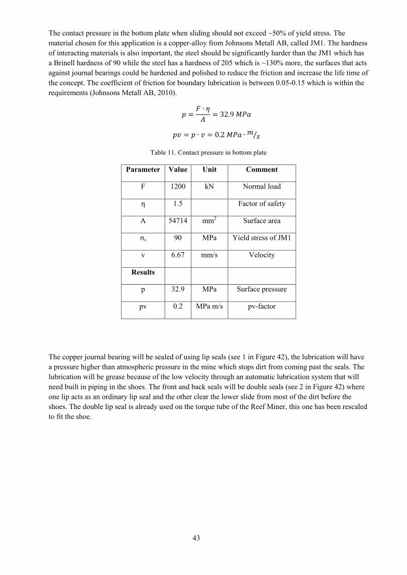
The contact pressure in the bottom plate when sliding should not exceed ~50% of yield stress. The
material chosen for this application is a copper-alloy from Johnsons Metall AB, called JM1. The hardness
of interacting materials is also important, the steel should be significantly harder than the JM1 which has
a Brinell hardness of 90 while the steel has a hardness of 205 which is ~130% more, the surfaces that acts
against journal bearings could be hardened and polished to reduce the friction and increase the life time of
the concept. The coefficient of friction for boundary lubrication is between 0.05-0.15 which is within the
requirements (Johnsons Metall AB, 2010).
𝑝 =𝐹 ∙ 𝜂
𝐴= 32.9 𝑀𝑃𝑎
𝑝𝑣 = 𝑝 ∙ 𝑣 = 0.2 𝑀𝑃𝑎 ∙ 𝑚 𝑠⁄
Table 11. Contact pressure in bottom plate
Parameter Value Unit Comment
F 1200 kN Normal load
η 1.5 Factor of safety
A 54714 mm2 Surface area
σs 90 MPa Yield stress of JM1
v 6.67 mm/s Velocity
Results
p 32.9 MPa Surface pressure
pv 0.2 MPa m/s pv-factor
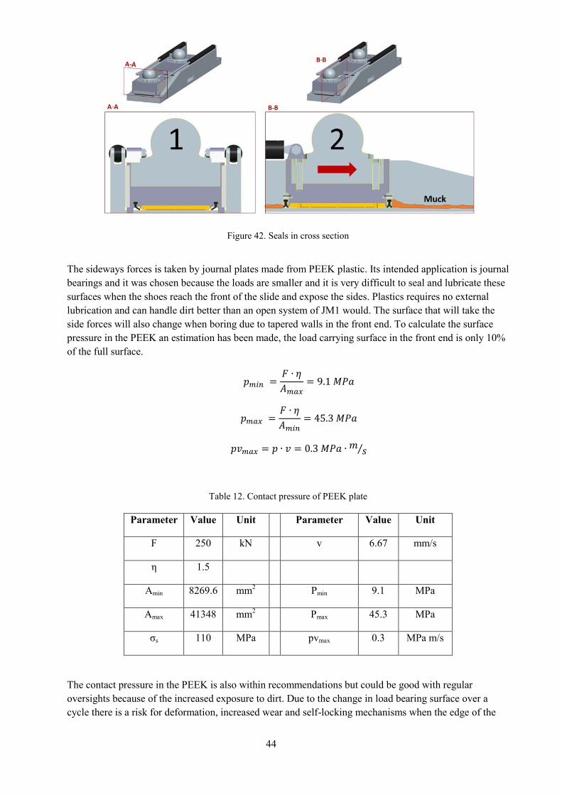
The copper journal bearing will be sealed of using lip seals (see 1 in Figure 42), the lubrication will have
a pressure higher than atmospheric pressure in the mine which stops dirt from coming past the seals. The
lubrication will be grease because of the low velocity through an automatic lubrication system that will
need built in piping in the shoes. The front and back seals will be double seals (see 2 in Figure 42) where
one lip acts as an ordinary lip seal and the other clear the lower slide from most of the dirt before the
shoes. The double lip seal is already used on the torque tube of the Reef Miner, this one has been rescaled
to fit the shoe.
44
Figure 42. Seals in cross section
The sideways forces is taken by journal plates made from PEEK plastic. Its intended application is journal
bearings and it was chosen because the loads are smaller and it is very difficult to seal and lubricate these
surfaces when the shoes reach the front of the slide and expose the sides. Plastics requires no external
lubrication and can handle dirt better than an open system of JM1 would. The surface that will take the
side forces will also change when boring due to tapered walls in the front end. To calculate the surface
pressure in the PEEK an estimation has been made, the load carrying surface in the front end is only 10%
of the full surface.
𝑝𝑚𝑖𝑛 =𝐹 ∙ 𝜂
𝐴𝑚𝑎𝑥= 9.1 𝑀𝑃𝑎
𝑝𝑚𝑎𝑥 =𝐹 ∙ 𝜂
𝐴𝑚𝑖𝑛= 45.3 𝑀𝑃𝑎
𝑝𝑣𝑚𝑎𝑥 = 𝑝 ∙ 𝑣 = 0.3 𝑀𝑃𝑎 ∙𝑚𝑠⁄
Table 12. Contact pressure of PEEK plate
Parameter Value Unit Parameter Value Unit
F 250 kN v 6.67 mm/s
η 1.5
Amin 8269.6 mm2 Pmin 9.1 MPa
Amax 41348 mm2 Pmax 45.3 MPa
σs 110 MPa pvmax 0.3 MPa m/s
The contact pressure in the PEEK is also within recommendations but could be good with regular
oversights because of the increased exposure to dirt. Due to the change in load bearing surface over a
cycle there is a risk for deformation, increased wear and self-locking mechanisms when the edge of the
45
wall move over the PEEK surface, the wall could be chamfered or rounded in the edges to provide a more
tapered interaction with the journal plate, by using a logarithmically curved end a good stress distribution
can be obtained (Beek, 2015).
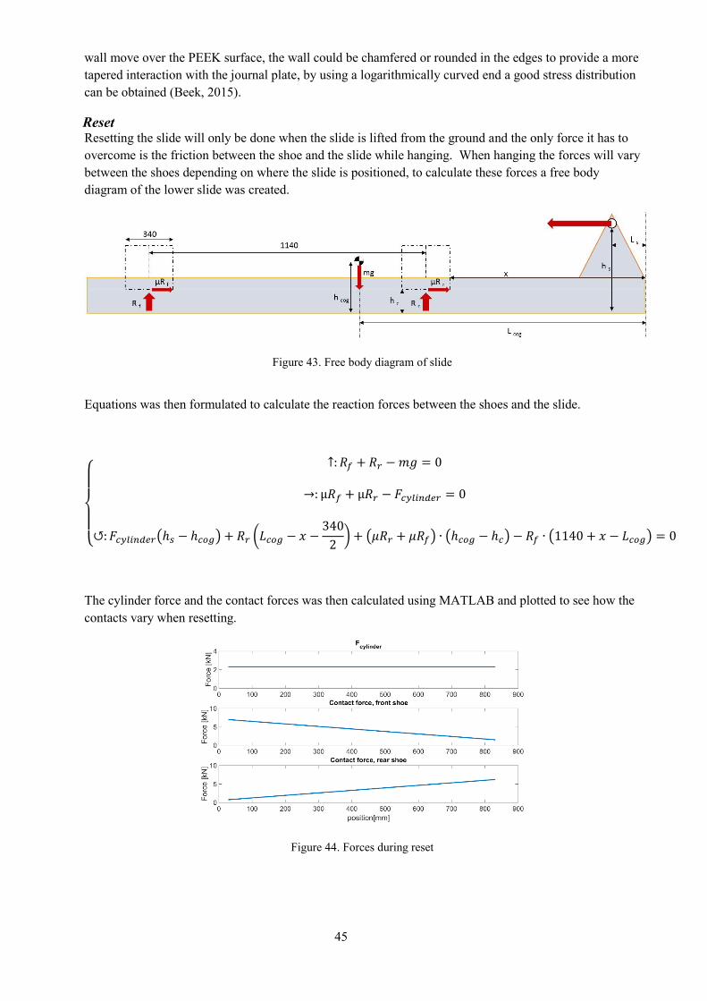
Reset Resetting the slide will only be done when the slide is lifted from the ground and the only force it has to
overcome is the friction between the shoe and the slide while hanging. When hanging the forces will vary
between the shoes depending on where the slide is positioned, to calculate these forces a free body
diagram of the lower slide was created.
Figure 43. Free body diagram of slide
Equations was then formulated to calculate the reaction forces between the shoes and the slide.
{
↑: 𝑅𝑓 + 𝑅𝑟 −𝑚𝑔 = 0
→: µ𝑅𝑓 + µ𝑅𝑟 − 𝐹𝑐𝑦𝑙𝑖𝑛𝑑𝑒𝑟 = 0
↺:𝐹𝑐𝑦𝑙𝑖𝑛𝑑𝑒𝑟(ℎ𝑠 − ℎ𝑐𝑜𝑔) + 𝑅𝑟 (𝐿𝑐𝑜𝑔 − 𝑥 −340
2) + (𝜇𝑅𝑟 + 𝜇𝑅𝑓) ∙ (ℎ𝑐𝑜𝑔 − ℎ𝑐) − 𝑅𝑓 ∙ (1140 + 𝑥 − 𝐿𝑐𝑜𝑔) = 0
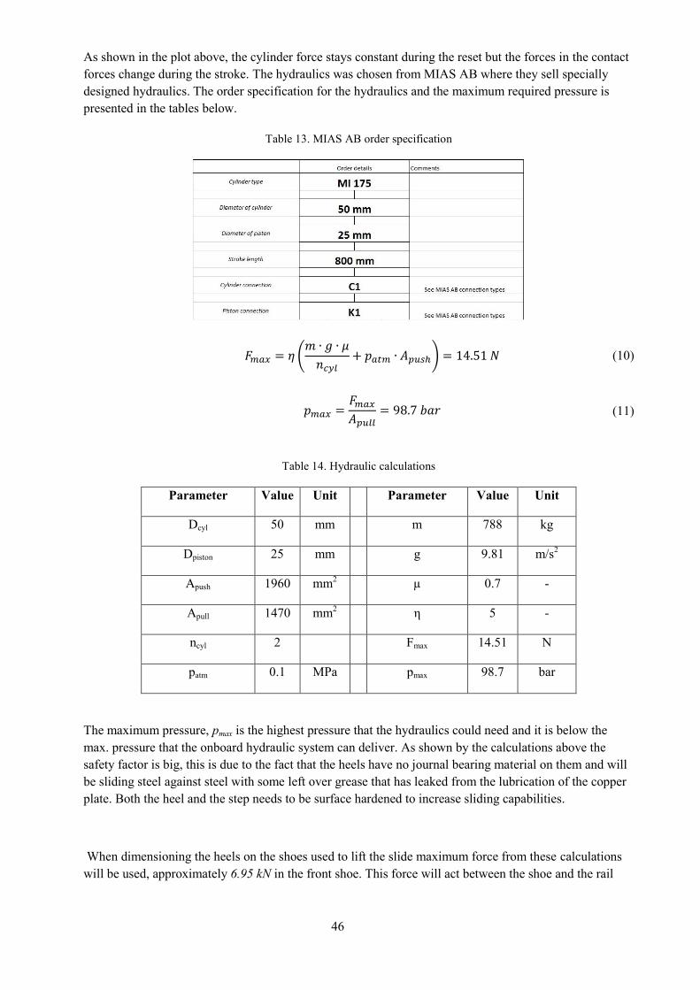
The cylinder force and the contact forces was then calculated using MATLAB and plotted to see how the
contacts vary when resetting.
Figure 44. Forces during reset
46
As shown in the plot above, the cylinder force stays constant during the reset but the forces in the contact
forces change during the stroke. The hydraulics was chosen from MIAS AB where they sell specially
designed hydraulics. The order specification for the hydraulics and the maximum required pressure is
presented in the tables below.
Table 13. MIAS AB order specification
𝐹𝑚𝑎𝑥 = 𝜂 (𝑚 ∙ 𝑔 ∙ 𝜇
𝑛𝑐𝑦𝑙+ 𝑝𝑎𝑡𝑚 ∙ 𝐴𝑝𝑢𝑠ℎ) = 14.51 𝑁 (10)
𝑝𝑚𝑎𝑥 =𝐹𝑚𝑎𝑥𝐴𝑝𝑢𝑙𝑙
= 98.7 𝑏𝑎𝑟 (11)
Table 14. Hydraulic calculations
Parameter Value Unit Parameter Value Unit
Dcyl 50 mm m 788 kg
Dpiston 25 mm g 9.81 m/s2
Apush 1960 mm2
µ 0.7 -
Apull 1470 mm2
η 5 -
ncyl 2 Fmax 14.51 N
patm 0.1 MPa pmax 98.7 bar
The maximum pressure, pmax is the highest pressure that the hydraulics could need and it is below the
max. pressure that the onboard hydraulic system can deliver. As shown by the calculations above the
safety factor is big, this is due to the fact that the heels have no journal bearing material on them and will
be sliding steel against steel with some left over grease that has leaked from the lubrication of the copper
plate. Both the heel and the step needs to be surface hardened to increase sliding capabilities.
When dimensioning the heels on the shoes used to lift the slide maximum force from these calculations
will be used, approximately 6.95 kN in the front shoe. This force will act between the shoe and the rail
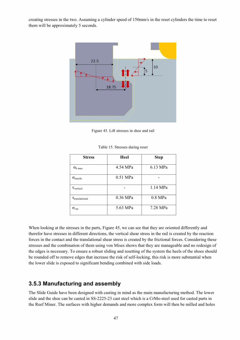
47
creating stresses in the two. Assuming a cylinder speed of 150mm/s in the reset cylinders the time to reset
them will be approximately 5 seconds.
Figure 45. Lift stresses in shoe and rail
Table 15. Stresses during reset
Stress Heel Step
σb max 4.54 MPa 6.13 MPa
σtensile 0.51 MPa -
τvertical - 1.14 MPa
τtranslational 0.36 MPa 0.8 MPa
σvm 5.63 MPa 7.28 MPa
When looking at the stresses in the parts, Figure 45, we can see that they are oriented differently and
therefor have stresses in different directions, the vertical shear stress in the rail is created by the reaction
forces in the contact and the translational shear stress is created by the frictional forces. Considering these
stresses and the combination of them using von Mises shows that they are manageable and no redesign of
the edges is necessary. To ensure a robust sliding and resetting of the system the heels of the shoes should
be rounded off to remove edges that increase the risk of self-locking, this risk is more substantial when
the lower slide is exposed to significant bending combined with side loads.
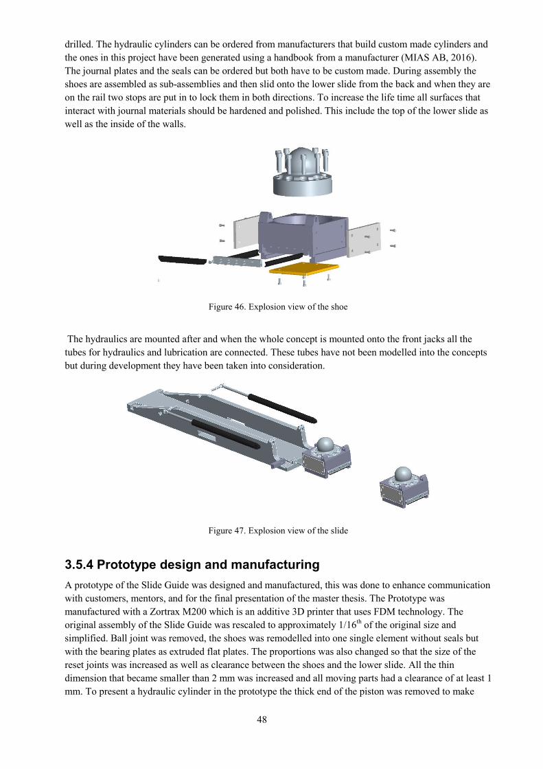
3.5.3 Manufacturing and assembly
The Slide Guide have been designed with casting in mind as the main manufacturing method. The lower
slide and the shoe can be casted in SS-2225-23 cast steel which is a CrMo-steel used for casted parts in
the Reef Miner. The surfaces with higher demands and more complex form will then be milled and holes
48
drilled. The hydraulic cylinders can be ordered from manufacturers that build custom made cylinders and
the ones in this project have been generated using a handbook from a manufacturer (MIAS AB, 2016).
The journal plates and the seals can be ordered but both have to be custom made. During assembly the
shoes are assembled as sub-assemblies and then slid onto the lower slide from the back and when they are
on the rail two stops are put in to lock them in both directions. To increase the life time all surfaces that
interact with journal materials should be hardened and polished. This include the top of the lower slide as
well as the inside of the walls.
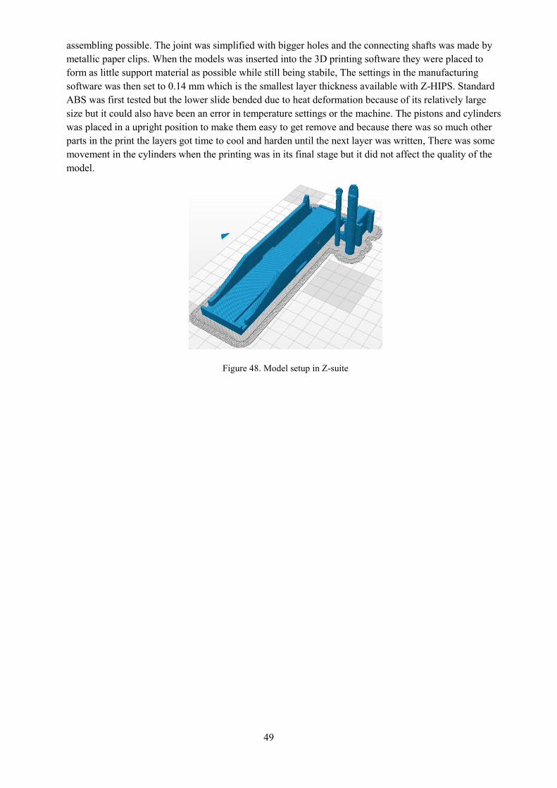
Figure 46. Explosion view of the shoe
The hydraulics are mounted after and when the whole concept is mounted onto the front jacks all the
tubes for hydraulics and lubrication are connected. These tubes have not been modelled into the concepts
but during development they have been taken into consideration.
Figure 47. Explosion view of the slide
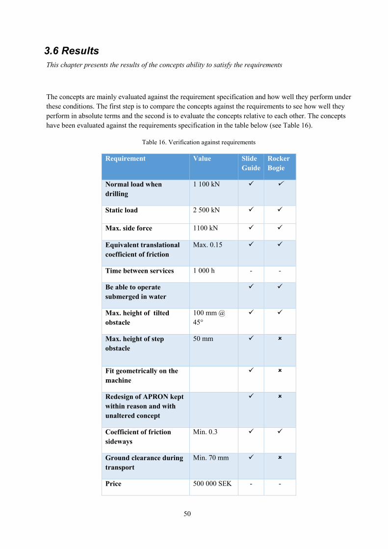
3.5.4 Prototype design and manufacturing
A prototype of the Slide Guide was designed and manufactured, this was done to enhance communication
with customers, mentors, and for the final presentation of the master thesis. The Prototype was
manufactured with a Zortrax M200 which is an additive 3D printer that uses FDM technology. The
original assembly of the Slide Guide was rescaled to approximately 1/16th of the original size and
simplified. Ball joint was removed, the shoes was remodelled into one single element without seals but
with the bearing plates as extruded flat plates. The proportions was also changed so that the size of the
reset joints was increased as well as clearance between the shoes and the lower slide. All the thin
dimension that became smaller than 2 mm was increased and all moving parts had a clearance of at least 1
mm. To present a hydraulic cylinder in the prototype the thick end of the piston was removed to make
49
assembling possible. The joint was simplified with bigger holes and the connecting shafts was made by
metallic paper clips. When the models was inserted into the 3D printing software they were placed to
form as little support material as possible while still being stabile, The settings in the manufacturing
software was then set to 0.14 mm which is the smallest layer thickness available with Z-HIPS. Standard
ABS was first tested but the lower slide bended due to heat deformation because of its relatively large
size but it could also have been an error in temperature settings or the machine. The pistons and cylinders
was placed in a upright position to make them easy to get remove and because there was so much other
parts in the print the layers got time to cool and harden until the next layer was written, There was some
movement in the cylinders when the printing was in its final stage but it did not affect the quality of the
model.
Figure 48. Model setup in Z-suite
50
3.6 Results
This chapter presents the results of the concepts ability to satisfy the requirements
The concepts are mainly evaluated against the requirement specification and how well they perform under
these conditions. The first step is to compare the concepts against the requirements to see how well they
perform in absolute terms and the second is to evaluate the concepts relative to each other. The concepts
have been evaluated against the requirements specification in the table below (see Table 16).
Table 16. Verification against requirements
Requirement Value Slide
Guide
Rocker
Bogie
Normal load when
drilling
1 100 kN
Static load 2 500 kN
Max. side force 1100 kN
Equivalent translational
coefficient of friction
Max. 0.15
Time between services 1 000 h - -
Be able to operate
submerged in water
Max. height of tilted
obstacle
100 mm @
45°
Max. height of step
obstacle
50 mm
Fit geometrically on the
machine
Redesign of APRON kept
within reason and with
unaltered concept
Coefficient of friction
sideways
Min. 0.3
Ground clearance during
transport
Min. 70 mm
Price 500 000 SEK - -
51
4 DISCUSSION AND CONCLUSION
The concepts have also been compared against each other in a larger sense. The Slide Guide is far
superior in terms of both requirements, robustness, and preferred by the customer Atlas Copco as well as
the mentors at Svea Teknik. They liked the simplicity and robustness of the Slide Guide and that it
synergies very well with the rest of the machines, simple and robust solutions. They also liked the
accidental advantage of the concepts ability to walk. If correctly controlled by the operator or
programmed software the machine can keep itself stabile using the two sides of the rear jacks and stingers
to keep it from tipping while one side of the front jacks is lifted to reset the slide, this can then be repeated
on the other side until the slides are reset without the need to lower the machine down on its tracks. This
was not an intentional use of the reset at first but when it was brought up at meetings it added an
additional advantage towards the Slide Guide. The Rocker Bogie was an interesting alternative concept
because of its wheel based design but might synergies better with an application that has its propulsion
acting on the wheels like a terrain vehicle for example, because the propulsion then acts as a torque on the
wheels to climb an obstacle far bigger than the wheel because the force on the center of the wheel acts
tangential to the circumference of the wheel at the point of contact. This means that if the wheel hit an
obstacle that contacts the wheel at the same height as the center of rotation the torque applied to the wheel
will push the wheel straight up until it has climbed the obstacle. Without the propulsion in the wheels the
concept becomes less efficient and requires a larger wheel size.
The Slide Guide clears more requirements than the Rocker Bogie. The Rocker Bogie had some more
issues with the requirements. The 50mm obstacle could be an issue depending on how it is modeled.
Considering a stiff 50 mm obstacle the wheels are too small because of the small space available, and the
wheels still cannot satisfy the ground clearance condition from the requirement specification. Assuming
that the rock is crushed by the wheels make it possible but that needs to be verified with several tests to
ensure that the system is robust against different types of stiff obstacles. The geometric requirement is not
fulfilled mainly because of the width of the concept. The wheels need this width to achieve a contact
pressure below the yield stress. The front bogie also intersects with the Apron which would require an
extensive redesign to keep its functionality. This is due to the fact that the ball joint needs space between
the wheels and combined with the wheel diameter make the whole bogie to long. The general problem
with all wheel concepts have been that the space they need to achieve a good contact pressure and low
friction over bumpy terrain is far more than the space available at this machine, a total redesign with
wheels in mind from the beginning is needed to make this work using wheels.
There are two requirements that have not been verified, price and life time. This is due to the difficult
nature of these requirements. Since the concepts are design with few standard components the main factor
when it comes to pricing is manufacturing and raw materials, these prices depend a lot on the workshop.
If the price becomes too high some changes can be made to the lower slide to reduce weight and material
needed, this could however require a more advanced casting procedure with fillings that are later
removed. The price requirements is regarded as a wish instead of a demand which means that it is less
important to the customer than the other requirements. The life time of the concepts is also difficult to
estimate, some calculations to ensure that the concepts will handle the fatigue has been made. To make an
estimate of the life time there are a lot of assumptions that needs to be made, how the loads vary, the
contamination from dust, moist and muck, rock chips flying around, and different qualities of the floor for
example. All these factor could be considered variables in a very complex life time estimation and simple
assumptions without experience in a mine might be misleading. That is why no life time calculations have
been made but extensive testing is very beneficial to get quantitative data that verify the life time of the
concepts.

52

53
5 RECOMMENDATIONS AND FUTURE WORK
5.1 Recommendations for future work
Sub components in the concepts might need additional evaluation to verify the functionality,
Slide Guide: Seals, PEEK plastic, lubrication and hydraulics
Rocker bogie: sealing solution and lubrication
The Slide Guide could benefit from being closed off with a gaiter reducing the risk of
contaminating the journal bearing plates
The life time of the concepts could be too complex to calculate, testing is required for both
concept to ensure that they fill the requirements.
The torque used when dimensioning the link plate in the Rocker Bogie is an assumption and
might need verification and/or testing
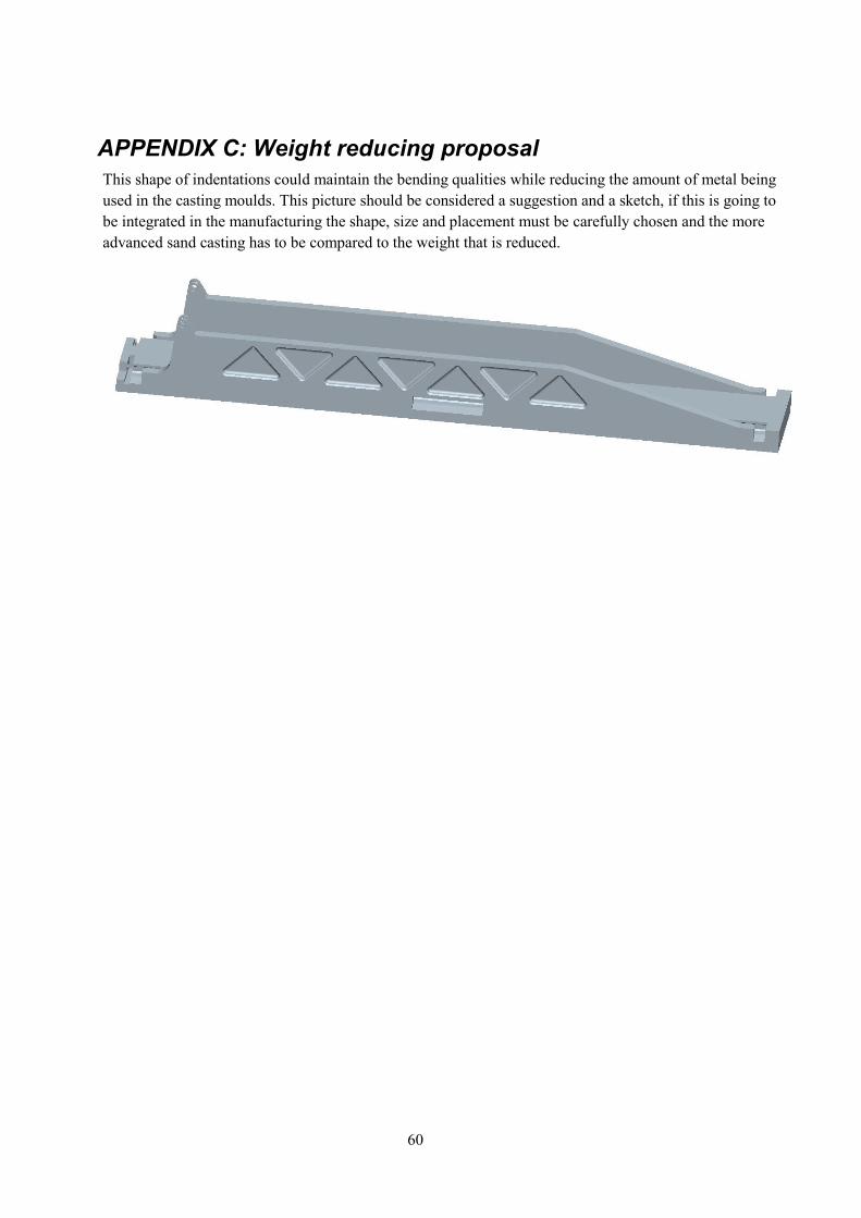
A proposal of weight reducing features have been created which would reduce the weight of the
lower slide with about 100 kg. This is done with molds that reduce the volume of metal in the
walls and slide while still maintaining good bending qualities. This requires a more advanced
sand casting with several steps and sub molts that are vibrated off the component when it is
finished. A cost calculation comparing weight against more advanced manufacturing is
recommended. The proposal have not been verified with calculations and is based on engineering
intuition (See Appendix C).
The Rocker Bogie wheel lids should be properly designed, these are sketched with no screws or
mounts in this project but with a groove for an o-ring. These should be redesigned or even
integrated in the wheel hubs to reduce the number of components and get a tighter fit against
lubrication leaks. The inside of the chassi could also be fitted with rough brushes so when the
wheels turn the brushes removes most of the dirt before it rotates up to the shaft and bearing, this
can reduce contamination from the inside of the chassi.
The width of the Slide Guide could be reduced with further load analysis and testing.
The back end of the lower slide could benefit from being redesigned to reduce concentrations of
stress in corners
The hydraulics of the Slide guide needs to be integrated in the existing hydraulic system and
controlled by the operator or an computer system
Piping for the lubrication of both concepts needs to be designed.

54
55
REFERENCES
(2008, January 16). Retrieved 05 26, 2016, from PTC:
http://support.ptc.com/appserver/wcms/standards/textsub.jsp?&im_dbkey=65281
Beek, A. V. (2015). Advanced Engineering Design, Lifetime performance and reliability. Delft.
Björk, K. (6th edition). Formler of tabeller för mekanisk konstruktion. Karl Björk Förlag HB.
Björklund, S. (2015). KARLEBO Handbok. Malmö: Liber AB.
Fredrik Saf, A. L. (2016, 02 02). 1st meeting with Fredrik. (P. Grelsson, Interviewer)
Jeb Design Magazine. (2013, 07 29). Stair-Rover Skateboard Longboard by Po-Chich Lai. Retrieved 05
26, 2016, from Youtube: https://www.youtube.com/watch?v=v9CqadQHCoM
Johnson Metall AB. (1989). Glidlager, Fettsmorda och självsmörjande. Örebro: Ingvar Essinger.
Retrieved 05 26, 2016
Johnsons Metall AB. (2010). Material guide. Örebro: Trio Tryck AB.
Kohlswa guteri AB. (n.d.). Kohlswa guteri. Retrieved june 10, 2016, from Kohlswa guteri AB:
http://www.kohlswagjuteri.se/material-
seghardningsstal.asp?activeImg=material&activeLang=se&activeChild=
Mars Pathfinder Fact sheet. (1997, 03 19). Retrieved 02 29, 2016, from NASA:
http://mars.jpl.nasa.gov/MPF/mpf/fact_sheet.html
Maskinelement, Handbok. (2008). Stockholm: Institutionen för Maskinkonstruktion.
MIAS AB. (2016, 05 16). Retrieved from MIAS AB:
http://www.miasab.se/dokument/Hydraulcylindrar/MI-
175_Cylinderbroschyr_MIASAB_150602.pdf
Swincar Official. (2013, 07 29). Stair-Rover Longboard by PoChich Lai. Retrieved 05 26, 2016, from
Youtube: https://www.youtube.com/watch?v=xdM5yCBy0jY
Ullman, D. G. (2010). The Mechanical Design Process. New York: Mcgraw-Hill.
Worlds fastest Tank. (1931, 01 22). Retrieved 05 18, 2016, from British Pathe:
http://www.britishpathe.com/video/worlds-fastest-tank-version-a

56
57
7 APPENDICES
58
APPENDIX A: QFD
59
APPENDIX B: Measurements of friction of existing design
60
APPENDIX C: Weight reducing proposal
This shape of indentations could maintain the bending qualities while reducing the amount of metal being
used in the casting moulds. This picture should be considered a suggestion and a sketch, if this is going to
be integrated in the manufacturing the shape, size and placement must be carefully chosen and the more
advanced sand casting has to be compared to the weight that is reduced.
61
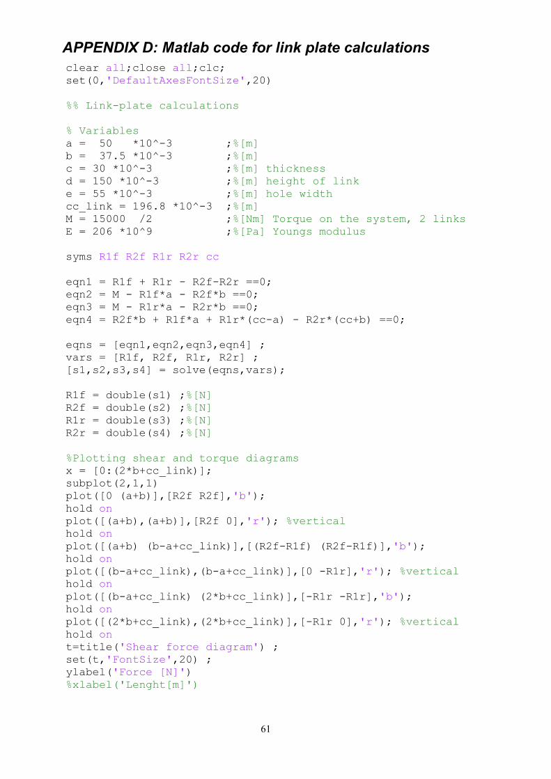
APPENDIX D: Matlab code for link plate calculations
clear all;close all;clc;
set(0,'DefaultAxesFontSize',20)
%% Link-plate calculations
% Variables
a = 50 *10^-3 ;%[m]
b = 37.5 *10^-3 ;%[m]
c = 30 *10^-3 ;%[m] thickness
d = 150 *10^-3 ;%[m] height of link
e = 55 *10^-3 ;%[m] hole width
cc_link = 196.8 *10^-3 ;%[m]
M = 15000 /2 ;%[Nm] Torque on the system, 2 links
E = 206 *10^9 ;%[Pa] Youngs modulus
syms R1f R2f R1r R2r cc
eqn1 = R1f + R1r - R2f-R2r ==0;
eqn2 = M - R1f*a - R2f*b ==0;
eqn3 = M - R1r*a - R2r*b ==0;
eqn4 = R2f*b + R1f*a + R1r*(cc-a) - R2r*(cc+b) ==0;
eqns = [eqn1,eqn2,eqn3,eqn4] ;
vars = [R1f, R2f, R1r, R2r] ;
[s1,s2,s3,s4] = solve(eqns,vars);
R1f = double(s1) ;%[N]
R2f = double(s2) ;%[N]
R1r = double(s3) ;%[N]
R2r = double(s4) ;%[N]
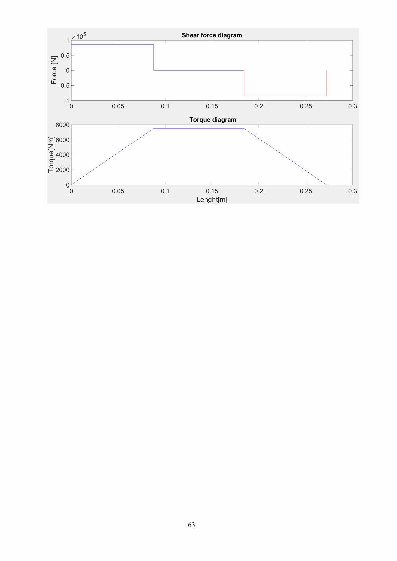
%Plotting shear and torque diagrams
x = [0:(2*b+cc_link)];
subplot(2,1,1)
plot([0 (a+b)],[R2f R2f],'b');
hold on
plot([(a+b),(a+b)],[R2f 0],'r'); %vertical
hold on
plot([(a+b) (b-a+cc_link)],[(R2f-R1f) (R2f-R1f)],'b');
hold on
plot([(b-a+cc_link),(b-a+cc_link)],[0 -R1r],'r'); %vertical
hold on
plot([(b-a+cc_link) (2*b+cc_link)],[-R1r -R1r],'b');
hold on
plot([(2*b+cc_link),(2*b+cc_link)],[-R1r 0],'r'); %vertical
hold on
t=title('Shear force diagram') ;
set(t,'FontSize',20) ;
ylabel('Force [N]')
%xlabel('Lenght[m]')
62
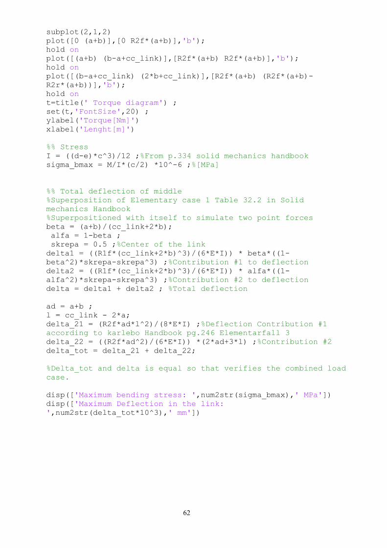
subplot(2,1,2)
plot([0 (a+b)],[0 R2f*(a+b)],'b');
hold on
plot([(a+b) (b-a+cc_link)],[R2f*(a+b) R2f*(a+b)],'b');
hold on
plot([(b-a+cc_link) (2*b+cc_link)],[R2f*(a+b) (R2f*(a+b)-
R2r*(a+b))],'b');
hold on
t=title(' Torque diagram') ;
set(t,'FontSize',20) ;
ylabel('Torque[Nm]')
xlabel('Lenght[m]')
%% Stress
I = ((d-e)*c^3)/12 ;%From p.334 solid mechanics handbook
sigma_bmax = M/I*(c/2) *10^-6 ;%[MPa]
%% Total deflection of middle
%Superposition of Elementary case 1 Table 32.2 in Solid
mechanics Handbook
%Superpositioned with itself to simulate two point forces
beta = (a+b)/(cc_link+2*b);
alfa = 1-beta ;
skrepa = 0.5 ;%Center of the link
delta1 = ((R1f*(cc_link+2*b)^3)/(6*E*I)) * beta*((1-
beta^2)*skrepa-skrepa^3) ;%Contribution #1 to deflection
delta2 = ((R1f*(cc_link+2*b)^3)/(6*E*I)) * alfa*((1-
alfa^2)*skrepa-skrepa^3) ;%Contribution #2 to deflection
delta = delta1 + delta2 ; %Total deflection
ad = a+b ;
l = cc_link - 2*a;
delta_21 = (R2f*ad*l^2)/(8*E*I) ;%Deflection Contribution #1
according to karlebo Handbook pg.246 Elementarfall 3
delta_22 = ((R2f*ad^2)/(6*E*I)) *(2*ad+3*l) ;%Contribution #2
delta_tot = delta_21 + delta_22;
%Delta_tot and delta is equal so that verifies the combined load
case.
disp(['Maximum bending stress: ',num2str(sigma_bmax),' MPa'])
disp(['Maximum Deflection in the link:
',num2str(delta_tot*10^3),' mm'])
63
64
APPENDIX E: Matlab code for reset hydraulics
clear all;close all;clc;
set(0,'DefaultAxesFontSize',20)
%% Reset Calculations
%Variables
m = 788.9 ;%[kg]
g = 9.81 ;
mg = m*g;
h_cog = 230.23*10^-3 ;%[m]
L_cog = 1164.4388*10^-3 ;%[m]
h_s = 270*10^-3 ;%[m]
L_s = 220*10^-3 ;%[m]
u = 0.7 ; %coeff. of friction
x = [830:-1:30];
w_shoe = 340/2 * 10^-3 ;%[m]
h_c = 70 * 10^-3 ;%[m]
cc_shoes = 1140 *10^-3 ;%[m]
x = [30:830] * 10^-3 ;%[m]
syms Fcyl Rf Rr xpos;
eqn_1 = -mg + Rf + Rr == 0 ;
eqn_2 = u*Rf + u*Rr - Fcyl == 0 ;
eqn_3 = Fcyl*(h_s-h_cog)+Rr*(L_cog-xpos-w_shoe)+u*Rr*(h_cog-h_c)
+ u*Rf*(h_cog-h_c) - Rf*(cc_shoes+xpos+w_shoe-L_cog) == 0;
eqns = [eqn_1,eqn_2,eqn_3] ;
vars = [Fcyl, Rf, Rr];
[s,s2,s3] = solve(eqns,vars);
%Extracted from solve and replaced xpos with x
Fcyl = 6381930250594419/2748779069440 ;%s
Rf =
252552667566970117662533083676603/35281291119633337834625040384
- (53182752088286825*x)/7834020347904 ;%s2
Rr = (53182752088286825*x)/7834020347904 +
20493090068604337222123373510725/35281291119633337834625040384
;%s3
Rf_max = max(Rf) ;
Rr_max = max(Rr) ;
figure(1)
subplot(3,1,1)
plot([x(1) x(end)]*10^3,[Fcyl Fcyl]*10^-3, 'Linewidth',3)
title('F_c_y_l_i_n_d_e_r')
%xlabel('position')
ylabel('Force [kN]')
%set(gca,'xticklabel',x)
t=title('F_c_y_l_i_n_d_e_r') ;
set(t,'FontSize',20) ;
subplot(3,1,2)
65
plot(x*10^3,Rf*10^-3, 'Linewidth',3)
%title('Contact force, front shoe')
t2=title('Contact force, front shoe');
set(t2,'FontSize',20) ;
%xlabel('position')
ylabel('Force [kN]')
subplot(3,1,3)
plot(x*10^3,Rr*10^-3, 'Linewidth',3)
%title('Contact force, rear shoe')
t3=title('Contact force, rear shoe') ;
set(t3,'FontSize',20);
xlabel('position[mm]')
ylabel('Force [kN]')
table(Fcyl,Rf_max,Rr_max) %[N]
%% Stresses
Rmax = max(Rf) ;%[N] Maximum reaction force
%Shoe
b_shoe = 304 * 10^-3 ;%[m]
h_shoe = 22.5 * 10^-3 ;%[m]
I_shoe = (b_shoe*h_shoe^3)/12 ;%Bending stiffness
A_shoe = (22.5*304)*2 ;%[mm2]
sigma_shear_shoe = u*Rmax/A_shoe ;%[MPa] shear stress in the
translational direction
sigma_t_shoe = Rmax/A_shoe ;%[MPa] Tensile stress in shoe
sigma_b_shoe = Rmax* (18.75*10^-3)/(I_shoe) * 11.25*10^-3 * 10^-
6 ;%[MPa] max. bending in shoe heel
sigma_vm_shoe =
sqrt((sigma_b_shoe+sigma_t_shoe)^2+3*sigma_shear_shoe^2) ;
%Rail
b_rail = 304 * 10^-3 ;%[m]
h_rail = 10 * 10^-3 ;%[m]
I_rail = (b_rail*h_rail^3)/12 ;%Bending stiffness
A_rail = 2*(10*304) ;%[mm2] shear tension area on rail. Can
consider total length of 2292mm if needed.
sigma_shear_rail = Rmax/A_rail ;%[MPa] shear stress in rail heel
sigma_shear2_rail = u*Rmax/A_rail ;%[MPa] shear stress in the
translational direction
sigma_b_rail = Rmax* (5*10^-3)/(I_rail) * 5*10^-3 * 10^-6
;%[MPa] max. bending in rail heel
sigma_vm_rail =
sqrt(sigma_b_rail^2+3*sigma_shear_rail^2+3*sigma_shear2_rail^2)
;%[MPa]
66
table(sigma_t_shoe,sigma_b_shoe, sigma_shear_shoe,
sigma_vm_shoe)
table(sigma_shear_rail,sigma_b_rail,sigma_shear2_rail,sigma_vm_r
ail)
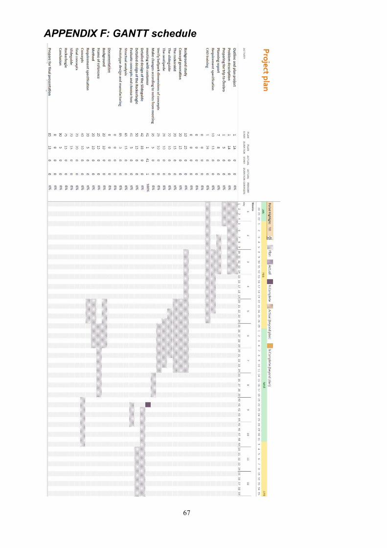
67
APPENDIX F: GANTT schedule
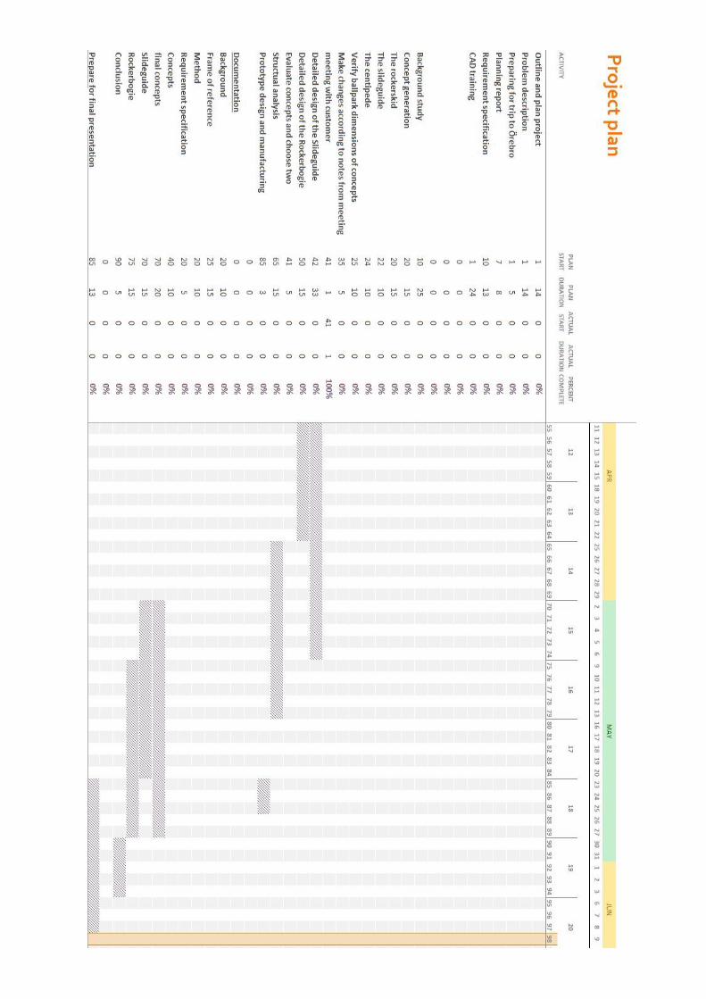
68