Front-end Realization of ASIC for Traffic Light Control...
9
International Journal of Computer Applications (0975 – 8887) 4th International IT Summit Confluence 2013 - The Next Generation Information Technology Summit 26 Front-end Realization of ASIC for Traffic Light Control with Real Time Clock Synchronization Mukul Bhargava M.Tech Scholar Deptt. of Elex. & Instr., Shri G.S. Institute of technology, Indore-452003 (M.P.) India Prashant P. Bansod Assoc. Prof. Deptt. of Elex. & Instr., Shri G.S. Institute of technology Indore-452003 (M.P.) India ABSTRACT In general all road traffic control system employed a variety of microcontroller based designs with added peripherals in order to perform control and timing management of traffic lights. The objective of this paper is to design an Application Specific Integrated Circuit (ASIC) for a road traffic light control and manage traffic light’s timing in accordance with time of the day or any special occasion and also be set manually. The VHSIC (Very High Speed Integrated Circuit) HDL (Hardware Description Language) or VHDL has been used as a programming language. ASIC reduces the system cost, area, power consumption and also well defined operational modes and timing management flexibility. GENERAL TERMS ASIC, VHDL, Traffic light control, Real time clock, Clock Divider, Clock Distributor, Straight Traffic, Crossed Traffic. KEYWORDS Traffic light control, VHDL based Traffic Control System, ASIC for Traffic Control, Traffic configurations, Real Time Clock Synchronization, Green, Red & Yellow light, Pedestrian Walk Signal Light, Night-mode, Rush-hour, Four-way Traffic, Y and T-shape Three-way Traffic, Down-counter display circuitry. 1. INTRODUCTION Control of Road traffic and essential management of light’s timing is the most crucial part of any city’s traffic system; either it is a small town or a large metropolitan city in any country. A road traffic control system requires a continuous set of operational instruction in any way to set green then yellow then red and again green light with particular timing of each colour light to pass/block vehicles way forward. A basic traffic light system has a set of three lights viz. Green, Red, Yellow on each road with provision of walk light and down counter on each road’s green and red light is the most popular system to be employed now-a-days. A down counter display help people to know that up to how much time they will have allowed when green light is ON and then up to how much time they will have to wait when red light is ON. 2. TYPES OF TRAFFIC JUNCTIONS There are various types of road crossings possible ranging from Three-way to five and six way but basically traffic light to employed for three and four-way traffic lights. Following four configurations of traffic are available in IC, 1. Basic Four ways Traffic 2. Traffic Four ways class-2 3. Y-shape Three ways traffic 4. T-shape Three ways traffic We will discuss these under main traffic block text in following sections. As shown in Fig. 1, following are main building blocks of IC, I. Clock Distributor Circuit. II. Main Traffic Block. III. Clock Divider circuit. IV. Manually settable real time clock (RTC). V. Blocks of 4 X 1 Multiplexer. 2.1 Clock Distributor Circuit This circuit mainly responsible for all kind of timing manipulation works in IC. Input pins to this circuit will allow user to change timing of green and yellow light for any specific road or a pair of two roads. It is also possible to have two roads subjected to change of timing have different timing to each other too that is both have different timing. Main inputs responsible for control such timing are red light signal of each road. Therefore as shown in figure 1 outputs of final multiplexer block is feedback to input of clock distributor block. Clock given at input is global clock.Mux_2X1 and Clk_Div_Sel are output of this block which are mainly utilized by clock divider circuit (will be discussed next) and main traffic block also.
Transcript of Front-end Realization of ASIC for Traffic Light Control...

International Journal of Computer Applications (0975 – 8887)
4th International IT Summit Confluence 2013 - The Next Generation Information Technology Summit
26
Front-end Realization of ASIC for Traffic Light Control with
Real Time Clock Synchronization
Mukul Bhargava M.Tech Scholar Deptt. of Elex. & Instr., Shri G.S. Institute of
technology, Indore-452003 (M.P.) India
Prashant P. Bansod
Assoc. Prof. Deptt. of Elex. & Instr., Shri G.S. Institute of
technology Indore-452003 (M.P.) India
ABSTRACT In general all road traffic control system employed a variety of
microcontroller based designs with added peripherals in order
to perform control and timing management of traffic lights. The
objective of this paper is to design an Application Specific
Integrated Circuit (ASIC) for a road traffic light control and
manage traffic light’s timing in accordance with time of the day
or any special occasion and also be set manually. The VHSIC
(Very High Speed Integrated Circuit) HDL (Hardware
Description Language) or VHDL has been used as a
programming language. ASIC reduces the system cost, area,
power consumption and also well defined operational modes
and timing management flexibility.
GENERAL TERMS ASIC, VHDL, Traffic light control, Real time clock, Clock
Divider, Clock Distributor, Straight Traffic, Crossed Traffic.
KEYWORDS Traffic light control, VHDL based Traffic Control System,
ASIC for Traffic Control, Traffic configurations, Real Time
Clock Synchronization, Green, Red & Yellow light, Pedestrian
Walk Signal Light, Night-mode, Rush-hour, Four-way Traffic,
Y and T-shape Three-way Traffic, Down-counter display
circuitry.
1. INTRODUCTION Control of Road traffic and essential management of light’s
timing is the most crucial part of any city’s traffic system;
either it is a small town or a large metropolitan city in any
country. A road traffic control system requires a continuous set
of operational instruction in any way to set green then yellow
then red and again green light with particular timing of each
colour light to pass/block vehicles way forward.
A basic traffic light system has a set of three lights viz. Green,
Red, Yellow on each road with provision of walk light and
down counter on each road’s green and red light is the most
popular system to be employed now-a-days. A down counter
display help people to know that up to how much time they will
have allowed when green light is ON and then up to how much
time they will have to wait when red light is ON.
2. TYPES OF TRAFFIC JUNCTIONS There are various types of road crossings possible ranging from
Three-way to five and six way but basically traffic light to
employed for three and four-way traffic lights. Following four
configurations of traffic are available in IC, 1. Basic Four ways Traffic
2. Traffic Four ways class-2
3. Y-shape Three ways traffic
4. T-shape Three ways traffic
We will discuss these under main traffic block text in following
sections.
As shown in Fig. 1, following are main building blocks of IC,
I. Clock Distributor Circuit.
II. Main Traffic Block.
III. Clock Divider circuit.
IV. Manually settable real time clock (RTC).
V. Blocks of 4 X 1 Multiplexer.
2.1 Clock Distributor Circuit This circuit mainly responsible for all kind of timing
manipulation works in IC. Input pins to this circuit will allow
user to change timing of green and yellow light for any specific
road or a pair of two roads. It is also possible to have two roads
subjected to change of timing have different timing to each
other too that is both have different timing.
Main inputs responsible for control such timing are red light
signal of each road. Therefore as shown in figure 1 outputs of
final multiplexer block is feedback to input of clock distributor
block. Clock given at input is global clock.Mux_2X1 and
Clk_Div_Sel are output of this block which are mainly utilized
by clock divider circuit (will be discussed next) and main traffic
block also.

International Journal of Computer Applications (0975 – 8887)
4th International IT Summit Confluence 2013 - The Next Generation Information Technology Summit
27
Fig. 1. Block diagram of circuitry
2.2 Clock Divider circuit This block decides with clock to be used as system clock for
main traffic block. Clock divider block have following clock
dividing functions viz.
a. Divide by 1.5
b. Divide by 2
c. Divide by 3
Mux_2X1 input select 15 sec. or 30 sec. clock by 2X1
multiplexer. Clk_Div_Sel input is a 2 bit input select 30,
45(divide by 1.5 clock divider), 60(divide by 2 clock divider),
90(divide by 3 clock divider) by 4X1 multiplexer. Thus clock
divider circuit can provide 15, 30, 45, 60 & 90 sec clocks. Thus
any of these clocks is given to output by Clk_main_out output
pin. Timer_Clk is another output of clock divider which giver
divide by 4 output for clock signal to timer sections (will
discuss in following text). A Clock Divider block diagram is
shown in Fig. 2.
Fig. 2. Clock Divider Block
2.3 Main Traffic Block Main traffic block constitute all four kind of traffic blocks viz.
a. Basic Four ways Traffic junction.
b. Traffic Four ways class-2 junction.
c. Y-shape Three ways traffic junction.
d. T-shape Three ways traffic junction.
2.3.1 Basic Four-ways Traffic Junction A basic four way traffic have 4 roads with each road have five
lights viz. red, green, yellow and walk signal plus down counter
display for red and green light. A typical pole with all lights
mounted is shown in fig. 3 as,
Fig. 3. Pole with traffic lights mounted
In this case walk signal remain ON until green signal arrow are
bright. To inform the pedestrian about end of walk signal,
before 4 seconds of its end,walk signal blinks i.e. on and off for
each second. Traffic lights become ON and OFF in clockwise
fashion on respected roads. Fig. 4 shows such an arrangement
2.3.2 Traffic Four ways class -2 Junction Traffic class-2 further subdivided in two categories viz.
1. Normal class-2 traffic
2. Special class-2 traffic
Selection between them is done by a special I/P
“Sub_Mod_Sel”.
International Journal of Computer Applications (0975 – 8887)
4th International IT Summit Confluence 2013 - The Next Generation Information Technology Summit
28
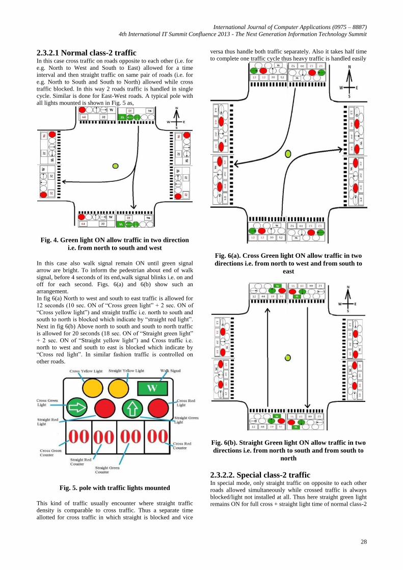
2.3.2.1 Normal class-2 traffic In this case cross traffic on roads opposite to each other (i.e. for
e.g. North to West and South to East) allowed for a time
interval and then straight traffic on same pair of roads (i.e. for
e.g. North to South and South to North) allowed while cross
traffic blocked. In this way 2 roads traffic is handled in single
cycle. Similar is done for East-West roads. A typical pole with
all lights mounted is shown in Fig. 5 as,
Fig. 4. Green light ON allow traffic in two direction
i.e. from north to south and west
In this case also walk signal remain ON until green signal
arrow are bright. To inform the pedestrian about end of walk
signal, before 4 seconds of its end,walk signal blinks i.e. on and
off for each second. Figs. 6(a) and 6(b) show such an
arrangement.
In fig 6(a) North to west and south to east traffic is allowed for
12 seconds (10 sec. ON of “Cross green light” + 2 sec. ON of
“Cross yellow light”) and straight traffic i.e. north to south and
south to north is blocked which indicate by “straight red light”.
Next in fig 6(b) Above north to south and south to north traffic
is allowed for 20 seconds (18 sec. ON of “Straight green light”
+ 2 sec. ON of “Straight yellow light”) and Cross traffic i.e.
north to west and south to east is blocked which indicate by
“Cross red light”. In similar fashion traffic is controlled on
other roads.
Fig. 5. pole with traffic lights mounted
This kind of traffic usually encounter where straight traffic
density is comparable to cross traffic. Thus a separate time
allotted for cross traffic in which straight is blocked and vice
versa thus handle both traffic separately. Also it takes half time
to complete one traffic cycle thus heavy traffic is handled easily
Fig. 6(a). Cross Green light ON allow traffic in two
directions i.e. from north to west and from south to
east
Fig. 6(b). Straight Green light ON allow traffic in two
directions i.e. from north to south and from south to
north
2.3.2.2. Special class-2 traffic In special mode, only straight traffic on opposite to each other
roads allowed simultaneously while crossed traffic is always
blocked/light not installed at all. Thus here straight green light
remains ON for full cross + straight light time of normal class-2

International Journal of Computer Applications (0975 – 8887)
4th International IT Summit Confluence 2013 - The Next Generation Information Technology Summit
29
traffic case. Similar is done for East-West roads. A typical pole
with all lights mounted is shown in Fig. 7 as,
2.3.3 Y-shape Three ways traffic This configuration is identical to basic four way traffic with
difference that now roads are three instead of four. Thus whole
traffic control process is identical to basic four way traffic. Fig
8 shows road 2 to road 3 have green light ON while other are
red for 32 seconds (30 seconds ON of green light + 2 seconds
ON of yellow light) and so on.
Fig. 7. Pole with traffic lights mounted
Fig. 8. Green light ON allow traffic
2.3.4 T-shape Three ways traffic It is special case of three-way traffic crossing. In such a case
three is a main road with large traffic density and a road with
comparably low traffic density is turned from such main road
thus making a T-shape traffic crossing, also known as T-point.
In such case main road have timing (of green light to pass the
traffic) is more than twice the timing of cross traffic from main
road to turned road /turned road to main road. Fig 9(a) below
shows road 1 to road 2 and road 2 to road 1 have green light
ON for 64 sec. (60 sec. ON of green light + 4 sec. ON of yellow
light) while road 1 to road 3 and road 3 to 2 have red light ON.
Fig. 9(a). Green light ON allow traffic
Next in Fig 9(b) shows road 1 to road 3 have green light
ON for 32 sec. (30 sec. ON of green light + 2 sec. ON of
yellow light) while road 3 to road 1,road 1 to 2 and road
2 to 1 have red light ON.
Fig. 9.(b) Green light ON allow traffic
2.4 Manually Settable Real Time Clock A real time clock is IC clock running by default in auto mode.
It can also be set manually. Main function of this clock is to
generate two very essential outputs, “Night mode enable” and
“Rush mode enable”. A night mode enable signal is input to
each traffic sub block of main traffic block. When this signal is
logic-1 makes all traffic lights off except yellow light blinks (1
second ON and 1 second off).Thus work of real time clock is to
generate night mode signal when night mode hour interval (to
be set manually) occurs.
Similarly rush mode enable signal (to be send input to clock
distributor block) timing of all or any one/two roads can be
changed (increase/decrease) manually. Thus function of
manually settable RTC is to generate rush mode enable signal
when rush hour interval (again similar night mode, can be set
manually for morning and evening) occurs. Specific input pins
provided for all such manual setting.RTC can also be set
manually to any hour minute and second time by setting value
at input and set “time set enable” input to logic-1.

International Journal of Computer Applications (0975 – 8887)
4th International IT Summit Confluence 2013 - The Next Generation Information Technology Summit
30
2.5 Blocks of 4X1 Multiplexer (Mux) Multiplexer block contains,
i. 4 Eight-bit input- eight-bit output 4X1 mux
ii. 4 Nine-bit input-nine-bit output 4X1 mux
iii. 28 One-bit input-one-bit output 4X1 mux
Select line to all these 36 mux is main IC input named,
Traffic_Sel which is a 2-bit input.
2.5.1 4 Eight-bit input- eight-bit output 4X1
mux Each 8-bit mux can select one of Green Count signal for a road
from a specific traffic configuration out of four kind of traffic
using Traffic_Sel input as select line. Therefore one mux for
each road.
2.5.2. 4 Nine-bit input-nine-bit output 4X1
mux Each 9-bit mux can select one of Green Count signal for a road
from a specific traffic configuration out of four kind of traffic
using Traffic_Sel input as select line. Therefore one mux for
each road.
2.5.3. 28 One-bit input-one-bit output 4X1
mux Each mux is for any specific traffic light. As there are seven
lights viz. green, green cross, red, red cross, yellow, yellow
cross, walk and for each road out of max 4 road s to its total 28
lights i.e. seven for each road thus, each mux select one light
for a specific traffic configuration out of four kind of traffic
using Traffic_Sel input as select line.
3. RTL SCHEMATIC OF IC Complete Logic coding of IC is done at Xilinx 8.1 ISE software
tool in VHSIC (Very High Speed Integrated Circuit) HDL
(Hardware Description Language) or VHDL. After synthesis,
following RTL schematic generated for the IC.
Fig 10 shows RTL top level schematic of complete IC. As
shown in fig IC has following input and output pins,
3.1 IC_Power_ON_Off Use to switch ON/Off the IC. Logic-0 Off & Logic-1 ON.
3.2 Clk Global clock Input. This clock is distributed to various sub
blocks of IC. Clock is generated by a clock generator.
Supported clock time period for the IC is 0.24 seconds i.e. 4Hz.
3.3 Clr Use to reset the IC to its default state. Logic-0 Reset
disables & Logic-1 Reset enables.
3.4 Emrgncy Use to Pass VIP, any emergency vehicle or in any special
case.Logic-0 for no action and normal traffic continue. Logic-1
for normal traffic paused and only the lane/road use by VIP is
allowed. Other lights are paused and remain in whatever
position they are.
Fig 10 RTL Schematic of IC
3.5 Walk_Enable Use to enable/Disable Walk signal. Logic-0 Walk Disable
Logic-1 Walk Enable.
3.6 Traffic_Sel (1:0) Use to select among various possible traffic configuration
Blocks. Logic-00: Four ways basic traffic crossing. Logic-01:
Four ways class-2 traffic. Logic-10: For Y-shape three-ways
traffic crossing. Logic-11: for T-shape three-ways traffic
crossing.
3.7 Man_Auto_Mod_sel Use to select mode of RTC. Logic-0 for Auto mode i.e. clock
work in auto mode and hence seconds, minutes and hours
cannot be set manually. Logic-1 for manual mode i.e. now
clock can be set manually to any value of second, minute and
hour as per need by giving I/P to sec_in, min_in and hour_in
I/Ps.

International Journal of Computer Applications (0975 – 8887)
4th International IT Summit Confluence 2013 - The Next Generation Information Technology Summit
31
3.8 Time_Set_Enable Use to allow sec_in, min_in and hour_in I/P to change the
current clock timing. Logic-0 for normal auto mode in work,
although manual mode is enable. Logic-1: for manual mode in
work if manual mode also must be enabling. And thus now I/P
from sec_in, min_in and hour_in can able change the clock
timing.
3.9 Sec_in (5:0)/ Min_in (5:0)/ Hour_in (4:0) Use to set Second/Minute/Hour timing of RTC.
3.10 Night_mod_Begin/End Hour (4:0) Use to set Night mode start/end Hour.
3.11
Morning/Evening_Rush_mod_Begin/End
Hour (4:0) A five bit I/P. Use to set morning time rush mode start Hour.
3.12 Mux_2X1_IP A single bit I/P. Use as select line for 2X1 mux of clock divider
3.13 Clk_div_sel_IP (1:0) A two bit I/P. Use as select line for 4X1 mux of clock divider
3.14 Variable_Time_Enable A single bit I/P. Use to Enable the Clock Distributor circuit so
that change of traffic light timing allowed. Alternatively this
can be controlled by one internal signal called Rush mode
enable signal.
3.15 No_of_Roads_Time_Var (1:0) Use to select among option of taking no. of roads whose timing
to be changed together. Logic-00 single road. Thus at most any
one road timing can be changed. Logic-01 two roads. Thus any
two roads timing can be changed individually. Logic-10 all four
roads different timing. Thus timing of all four road of a four
way crossing can be changed individually. Logic-11 all four
roads same timing. Thus timing of all four roads can be
changed together by setting inputs Mux_2X1_IP and
Clk_div_sel_IP (1:0).
3.16 TwoRoad_timing_same_diff A single bit I/P. Use to select between options of two roads
timing same or different.Logic-0 same timing & Logic-1
different timing.
3.17 Road_timing_Combination (2:0) A two bit I/P. Use to select between 6 possible combination of
two roads on a 4-way crossing. These are, Logic-000 Road 1
and 2, Logic-001 Road 1 and 3, Logic-010 Road 1 and 4,
Logic-011 Road 3 and 2, Logic-100 Road 3 and 4, Logic-101
Road 4 and 2.
3.18 Timing (1:0) Use to select between various timing of green light, Logic-00
for 15 Seconds, Logic-01 for 45 Seconds, Logic-10 for 60
Seconds, Logic-11 for 90 Seconds.
3.19 Sub_Mod_Sel Use to select between normal operation of Class-2 special
IC has 36 Outputs which are categorized in 5
classes viz.
3.20 Green Light O/Ps Green Cross1, Green Cross 2, Green Cross 3, Green Cross 4,
Green 1, Green 2, Green 3, Green 4
3.21 Yellow Light O/Ps Yellow Cross 1, Yellow Cross 2, Yellow Cross 3, Yellow Cross
4, Yellow 1, Yellow 2, Yellow 3, Yellow 4
3.22 Red Light O/Ps Red Cross 1, Red Cross 2, Red Cross 3, Red Cross 4, Red 1,
Red 2, Red 3, Red 4
3.23 Walk Light O/Ps Walk Cross 1, Walk Cross 2, Walk Cross 3, Walk Cross 4,
Walk 1, Walk 2, Walk 3, Walk 4
3.24 Down Count Display O/Ps Count Green 1, Count Green 2, Count Green 3, Count Green 4,
Count Red 1, Count Red 2, Count Red 3, Count Red 4.
Fig. 11 shows detailed block diagram of circuitry.

International Journal of Computer Applications (0975 – 8887)
4th International IT Summit Confluence 2013 - The Next Generation Information Technology Summit
32
Fig. 11. Detailed block diagram of Traffic Light Control circuitry
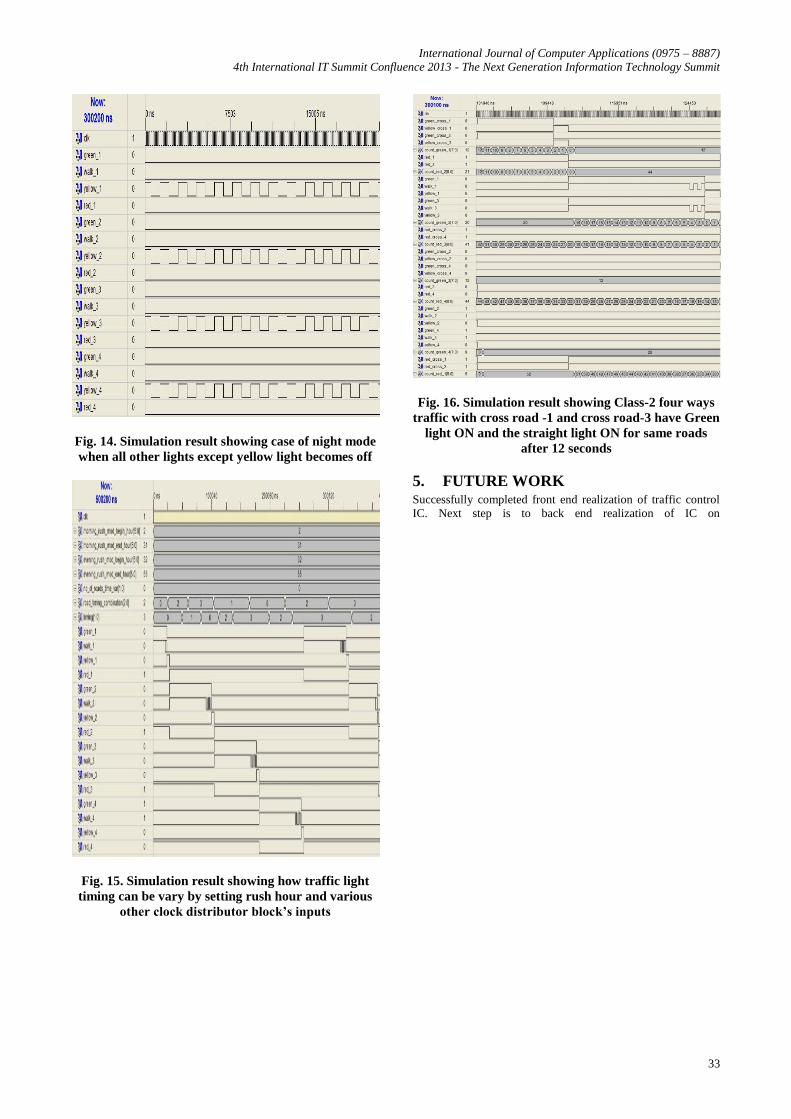
4. SIMULATION RESULTS After successful synthesis and the syntax check, behavioural
simulation of circuit is done using a no. of VHDL test benches
in Xilinx integrated software environment (ISE) simulator. The
simulator behaviour model generated is shown in fig 12 to 16
below.
Fig. 12. Simulation results showing basic controlling
input states applied to circuit
Fig. 13. Simulation result showing basic four ways
traffic with road -1 have Green light ON
International Journal of Computer Applications (0975 – 8887)
4th International IT Summit Confluence 2013 - The Next Generation Information Technology Summit
33
Fig. 14. Simulation result showing case of night mode
when all other lights except yellow light becomes off
Fig. 15. Simulation result showing how traffic light
timing can be vary by setting rush hour and various
other clock distributor block’s inputs
Fig. 16. Simulation result showing Class-2 four ways
traffic with cross road -1 and cross road-3 have Green
light ON and the straight light ON for same roads
after 12 seconds
5. FUTURE WORK Successfully completed front end realization of traffic control
IC. Next step is to back end realization of IC on

International Journal of Computer Applications (0975 – 8887)
4th International IT Summit Confluence 2013 - The Next Generation Information Technology Summit
34
Virtuoso Cadence IC design Environment, a electronic design
automation (EDA) tool. Future work will be to design optimum
power, high speed and low area IC using cadence EDA tool.
6. ACKNOWLEDGMENTS The authors wish to acknowledge the faculty at Department of
Electronic & Instrumentation Engineering, Shri Govindram
Seksaria Institute of Technology & Science, Indore, India for
their encouragement, help, support and guidance during the
theoretical study and preparation tenure of this design. The
authors wish to express their deep gratitude to all people who
helped directly or indirectly towards the successful completion
of this paper.
7. REFERENCES [1] J. Bhaskar (2010): ‘A VHDL Primer’, 3rd Ed., PHI
Learning Private Limited, New Delhi, India.
[2] Stephen A. Edwards (2011), ‘Writing VHDL for RTL
Synthesis’, Columbia University, USA
[3] ‘Practical Design of ASIC’ Edinburg Napier University,
United Kingdom.
[4] ‘Traffic light controller’ Milwaukee Area Technical
College, Milwaukee, Wisconsin, United States.
[5] ‘Digital Systems / VHDL’ Bremerhaven University,
Bremerhaven, Bremen, Federal Republic of Germany.