Object-Oriented Design Patterns CSC 335: Object-Oriented Programming and Design.

ibm.com/redbooks
Patterns: Service-Oriented Architecture and Web Servicesces
Mark EndreiJenny Ang
Ali ArsanjaniSook Chua
Philippe ComtePål Krogdahl
Min LuoTony Newling
Design service-oriented architectures using Web services
Explore service bus, directory, and gateway solutions
Learn by example with practical scenarios
Front cover


Patterns: Service-Oriented Architecture and Web Services
April 2004
International Technical Support Organization
SG24-6303-00

© Copyright International Business Machines Corporation 2004. All rights reserved.Note to U.S. Government Users Restricted Rights -- Use, duplication or disclosure restricted by GSA ADPSchedule Contract with IBM Corp.
First Edition (April 2004)
This edition applies to IBM WebSphere Application Server base V5.1, IBM WebSphere Application Server Network Deployment V5.0.2.4, IBM WebSphere MQ V5.3, and IBM WebSphere Studio Application Developer V5.1.1, for use with IBM AIX 5.1, Red Hat Linux Advanced Server V2.1, and Microsoft Windows 2000.
Note: Before using this information and the product it supports, read the information in “Notices” on page ix.

Contents
Notices . . . . . . . . . . . . . . . . . . . . . . . . . . . . . . . . . . . . . . . . . . . . . . . . . . . . . . . ixTrademarks . . . . . . . . . . . . . . . . . . . . . . . . . . . . . . . . . . . . . . . . . . . . . . . . . . . . x
Preface . . . . . . . . . . . . . . . . . . . . . . . . . . . . . . . . . . . . . . . . . . . . . . . . . . . . . . . xiThe team that wrote this redbook. . . . . . . . . . . . . . . . . . . . . . . . . . . . . . . . . . . . xiBecome a published author . . . . . . . . . . . . . . . . . . . . . . . . . . . . . . . . . . . . . . . xivComments welcome. . . . . . . . . . . . . . . . . . . . . . . . . . . . . . . . . . . . . . . . . . . . . xiv
Chapter 1. Patterns for e-business . . . . . . . . . . . . . . . . . . . . . . . . . . . . . . . . 11.1 The Patterns for e-business layered asset model . . . . . . . . . . . . . . . . . . . . 31.2 How to use the Patterns for e-business . . . . . . . . . . . . . . . . . . . . . . . . . . . 4
1.2.1 Business, Integration, or Composite pattern, or a Custom design . . . 51.2.2 Selecting Application patterns. . . . . . . . . . . . . . . . . . . . . . . . . . . . . . 101.2.3 Review Runtime patterns . . . . . . . . . . . . . . . . . . . . . . . . . . . . . . . . . 111.2.4 Review Product mappings . . . . . . . . . . . . . . . . . . . . . . . . . . . . . . . . 141.2.5 Review guidelines and related links . . . . . . . . . . . . . . . . . . . . . . . . . 14
1.3 Summary . . . . . . . . . . . . . . . . . . . . . . . . . . . . . . . . . . . . . . . . . . . . . . . . . . 15
Chapter 2. Service-oriented architecture . . . . . . . . . . . . . . . . . . . . . . . . . . 172.1 Overview of service-oriented architecture . . . . . . . . . . . . . . . . . . . . . . . . . 18
2.1.1 The business drivers for a new approach . . . . . . . . . . . . . . . . . . . . . 182.1.2 Service-oriented architecture as a solution . . . . . . . . . . . . . . . . . . . . 202.1.3 A closer look at service-oriented architecture . . . . . . . . . . . . . . . . . . 242.1.4 Service-oriented architecture benefits. . . . . . . . . . . . . . . . . . . . . . . . 30
2.2 Web services architecture . . . . . . . . . . . . . . . . . . . . . . . . . . . . . . . . . . . . . 312.2.1 What Web services are . . . . . . . . . . . . . . . . . . . . . . . . . . . . . . . . . . . 312.2.2 Web service interoperability . . . . . . . . . . . . . . . . . . . . . . . . . . . . . . . 34
2.3 Web services and service-oriented architecture . . . . . . . . . . . . . . . . . . . . 372.4 Enterprise Service Bus . . . . . . . . . . . . . . . . . . . . . . . . . . . . . . . . . . . . . . . 38
2.4.1 Basic Web services. . . . . . . . . . . . . . . . . . . . . . . . . . . . . . . . . . . . . . 382.4.2 What an Enterprise Service Bus is . . . . . . . . . . . . . . . . . . . . . . . . . . 392.4.3 The IBM vision . . . . . . . . . . . . . . . . . . . . . . . . . . . . . . . . . . . . . . . . . 40
2.5 Where to find more information . . . . . . . . . . . . . . . . . . . . . . . . . . . . . . . . . 43
Chapter 3. Service-oriented architecture and Patterns for e-business . . 453.1 Using service-oriented architecture with Patterns for e-business . . . . . . . 463.2 Self-Service business pattern . . . . . . . . . . . . . . . . . . . . . . . . . . . . . . . . . . 473.3 Extended Enterprise business pattern . . . . . . . . . . . . . . . . . . . . . . . . . . . 483.4 Application Integration pattern. . . . . . . . . . . . . . . . . . . . . . . . . . . . . . . . . . 49
© Copyright IBM Corp. 2004. All rights reserved. iii

3.4.1 Process Integration concepts . . . . . . . . . . . . . . . . . . . . . . . . . . . . . . 493.4.2 Application Integration application patterns . . . . . . . . . . . . . . . . . . . 503.4.3 Direct Connection application pattern . . . . . . . . . . . . . . . . . . . . . . . . 523.4.4 Broker application pattern . . . . . . . . . . . . . . . . . . . . . . . . . . . . . . . . . 543.4.5 Serial Process application pattern. . . . . . . . . . . . . . . . . . . . . . . . . . . 553.4.6 Parallel Process application pattern . . . . . . . . . . . . . . . . . . . . . . . . . 57
3.5 Runtime patterns . . . . . . . . . . . . . . . . . . . . . . . . . . . . . . . . . . . . . . . . . . . . 583.5.1 Node types . . . . . . . . . . . . . . . . . . . . . . . . . . . . . . . . . . . . . . . . . . . . 583.5.2 Runtime patterns for Direct Connection . . . . . . . . . . . . . . . . . . . . . . 623.5.3 Runtime patterns for Broker . . . . . . . . . . . . . . . . . . . . . . . . . . . . . . . 67
3.6 Product mappings . . . . . . . . . . . . . . . . . . . . . . . . . . . . . . . . . . . . . . . . . . . 693.6.1 Products used in these mappings . . . . . . . . . . . . . . . . . . . . . . . . . . . 703.6.2 Product mappings . . . . . . . . . . . . . . . . . . . . . . . . . . . . . . . . . . . . . . . 72
Chapter 4. Service-oriented architecture approach . . . . . . . . . . . . . . . . . . 794.1 The SOA approach and Patterns for e-business. . . . . . . . . . . . . . . . . . . . 80
4.1.1 Service identification . . . . . . . . . . . . . . . . . . . . . . . . . . . . . . . . . . . . . 804.1.2 Patterns for e-business and SOA . . . . . . . . . . . . . . . . . . . . . . . . . . . 80
4.2 Business scenario: Supply chain management. . . . . . . . . . . . . . . . . . . . . 824.3 Steps of the SOA approach. . . . . . . . . . . . . . . . . . . . . . . . . . . . . . . . . . . . 83
4.3.1 Domain decomposition . . . . . . . . . . . . . . . . . . . . . . . . . . . . . . . . . . . 854.3.2 Goal-service model creation . . . . . . . . . . . . . . . . . . . . . . . . . . . . . . . 904.3.3 Subsystem analysis . . . . . . . . . . . . . . . . . . . . . . . . . . . . . . . . . . . . . 924.3.4 Service allocation . . . . . . . . . . . . . . . . . . . . . . . . . . . . . . . . . . . . . . . 964.3.5 Component specification. . . . . . . . . . . . . . . . . . . . . . . . . . . . . . . . . . 974.3.6 Structure components and services using patterns . . . . . . . . . . . . . 984.3.7 Technology realization mapping . . . . . . . . . . . . . . . . . . . . . . . . . . . 100
4.4 Summary and conclusion . . . . . . . . . . . . . . . . . . . . . . . . . . . . . . . . . . . . 1044.5 Where to find more information . . . . . . . . . . . . . . . . . . . . . . . . . . . . . . . . 104
Chapter 5. Technology options . . . . . . . . . . . . . . . . . . . . . . . . . . . . . . . . . 1075.1 Introduction . . . . . . . . . . . . . . . . . . . . . . . . . . . . . . . . . . . . . . . . . . . . . . . 109
5.1.1 Advantages of Web services. . . . . . . . . . . . . . . . . . . . . . . . . . . . . . 1095.1.2 Disadvantages of Web services . . . . . . . . . . . . . . . . . . . . . . . . . . . 109
5.2 Transport . . . . . . . . . . . . . . . . . . . . . . . . . . . . . . . . . . . . . . . . . . . . . . . . . 1105.2.1 HTTP. . . . . . . . . . . . . . . . . . . . . . . . . . . . . . . . . . . . . . . . . . . . . . . . 1105.2.2 Java Message Service . . . . . . . . . . . . . . . . . . . . . . . . . . . . . . . . . . 1115.2.3 Simple Mail Transfer Protocol . . . . . . . . . . . . . . . . . . . . . . . . . . . . . 1135.2.4 HTTPR . . . . . . . . . . . . . . . . . . . . . . . . . . . . . . . . . . . . . . . . . . . . . . 1155.2.5 Emerging standards for transport . . . . . . . . . . . . . . . . . . . . . . . . . . 115
5.3 Service communication protocol . . . . . . . . . . . . . . . . . . . . . . . . . . . . . . . 1165.3.1 SOAP . . . . . . . . . . . . . . . . . . . . . . . . . . . . . . . . . . . . . . . . . . . . . . . 117
5.4 Service description . . . . . . . . . . . . . . . . . . . . . . . . . . . . . . . . . . . . . . . . . 120
iv Patterns: Service-Oriented Architecture and Web Services

5.4.1 XML. . . . . . . . . . . . . . . . . . . . . . . . . . . . . . . . . . . . . . . . . . . . . . . . . 1215.4.2 WSDL . . . . . . . . . . . . . . . . . . . . . . . . . . . . . . . . . . . . . . . . . . . . . . . 1235.4.3 ebXML. . . . . . . . . . . . . . . . . . . . . . . . . . . . . . . . . . . . . . . . . . . . . . . 125
5.5 Service . . . . . . . . . . . . . . . . . . . . . . . . . . . . . . . . . . . . . . . . . . . . . . . . . . 1285.5.1 Web services and J2EE . . . . . . . . . . . . . . . . . . . . . . . . . . . . . . . . . 1295.5.2 Web Services Invocation Framework . . . . . . . . . . . . . . . . . . . . . . . 132
5.6 Business process . . . . . . . . . . . . . . . . . . . . . . . . . . . . . . . . . . . . . . . . . . 1335.6.1 WSFL and XLANG . . . . . . . . . . . . . . . . . . . . . . . . . . . . . . . . . . . . . 1355.6.2 Emerging standards for business process . . . . . . . . . . . . . . . . . . . 136
5.7 Service registry . . . . . . . . . . . . . . . . . . . . . . . . . . . . . . . . . . . . . . . . . . . . 1395.7.1 Static and dynamic Web services . . . . . . . . . . . . . . . . . . . . . . . . . . 1405.7.2 UDDI . . . . . . . . . . . . . . . . . . . . . . . . . . . . . . . . . . . . . . . . . . . . . . . . 1415.7.3 Emerging standards for service registry . . . . . . . . . . . . . . . . . . . . . 143
5.8 Policy. . . . . . . . . . . . . . . . . . . . . . . . . . . . . . . . . . . . . . . . . . . . . . . . . . . . 1445.8.1 Emerging standards for policy. . . . . . . . . . . . . . . . . . . . . . . . . . . . . 144
5.9 Security . . . . . . . . . . . . . . . . . . . . . . . . . . . . . . . . . . . . . . . . . . . . . . . . . . 1455.9.1 Security at the transport layer . . . . . . . . . . . . . . . . . . . . . . . . . . . . . 1495.9.2 Security at the service communication protocol layer . . . . . . . . . . . 1505.9.3 Security at the service description layer . . . . . . . . . . . . . . . . . . . . . 1505.9.4 Emerging standards for security . . . . . . . . . . . . . . . . . . . . . . . . . . . 1515.9.5 Where to find more information. . . . . . . . . . . . . . . . . . . . . . . . . . . . 153
5.10 Transaction . . . . . . . . . . . . . . . . . . . . . . . . . . . . . . . . . . . . . . . . . . . . . . 1535.10.1 Emerging standards for transaction . . . . . . . . . . . . . . . . . . . . . . . 1545.10.2 Where to find more information. . . . . . . . . . . . . . . . . . . . . . . . . . . 155
5.11 Management . . . . . . . . . . . . . . . . . . . . . . . . . . . . . . . . . . . . . . . . . . . . . 1565.11.1 Emerging standards for management . . . . . . . . . . . . . . . . . . . . . . 157
Chapter 6. HTTP service bus . . . . . . . . . . . . . . . . . . . . . . . . . . . . . . . . . . . 1596.1 Business scenario . . . . . . . . . . . . . . . . . . . . . . . . . . . . . . . . . . . . . . . . . . 1606.2 Design guidelines . . . . . . . . . . . . . . . . . . . . . . . . . . . . . . . . . . . . . . . . . . 160
6.2.1 Design overview . . . . . . . . . . . . . . . . . . . . . . . . . . . . . . . . . . . . . . . 1616.2.2 Service design considerations . . . . . . . . . . . . . . . . . . . . . . . . . . . . 1646.2.3 Component design considerations . . . . . . . . . . . . . . . . . . . . . . . . . 1806.2.4 Object design considerations . . . . . . . . . . . . . . . . . . . . . . . . . . . . . 186
6.3 Development guidelines . . . . . . . . . . . . . . . . . . . . . . . . . . . . . . . . . . . . . 1876.3.1 Getting started. . . . . . . . . . . . . . . . . . . . . . . . . . . . . . . . . . . . . . . . . 1886.3.2 Importing the supplied WSDL files . . . . . . . . . . . . . . . . . . . . . . . . . 1886.3.3 Service development considerations . . . . . . . . . . . . . . . . . . . . . . . 1906.3.4 Service consumer (client) development considerations . . . . . . . . . 2006.3.5 Testing considerations . . . . . . . . . . . . . . . . . . . . . . . . . . . . . . . . . . 210
6.4 Runtime guidelines . . . . . . . . . . . . . . . . . . . . . . . . . . . . . . . . . . . . . . . . . 2146.4.1 Service deployment considerations . . . . . . . . . . . . . . . . . . . . . . . . 214
6.5 Best practices . . . . . . . . . . . . . . . . . . . . . . . . . . . . . . . . . . . . . . . . . . . . . 223
Contents v

6.5.1 Design best practices . . . . . . . . . . . . . . . . . . . . . . . . . . . . . . . . . . . 2246.5.2 Interoperability best practices . . . . . . . . . . . . . . . . . . . . . . . . . . . . . 2256.5.3 Java implementation best practices . . . . . . . . . . . . . . . . . . . . . . . . 2256.5.4 Performance best practices . . . . . . . . . . . . . . . . . . . . . . . . . . . . . . 226
Chapter 7. JMS service bus . . . . . . . . . . . . . . . . . . . . . . . . . . . . . . . . . . . . 2297.1 Business scenario . . . . . . . . . . . . . . . . . . . . . . . . . . . . . . . . . . . . . . . . . . 2307.2 Design guidelines . . . . . . . . . . . . . . . . . . . . . . . . . . . . . . . . . . . . . . . . . . 230
7.2.1 Design overview . . . . . . . . . . . . . . . . . . . . . . . . . . . . . . . . . . . . . . . 2317.2.2 Service design considerations . . . . . . . . . . . . . . . . . . . . . . . . . . . . 2337.2.3 Component design considerations . . . . . . . . . . . . . . . . . . . . . . . . . 2377.2.4 Object design considerations . . . . . . . . . . . . . . . . . . . . . . . . . . . . . 238
7.3 Development guidelines . . . . . . . . . . . . . . . . . . . . . . . . . . . . . . . . . . . . . 2387.3.1 Service development considerations . . . . . . . . . . . . . . . . . . . . . . . 2387.3.2 Service consumer (client) development considerations . . . . . . . . . 245
7.4 Runtime guidelines . . . . . . . . . . . . . . . . . . . . . . . . . . . . . . . . . . . . . . . . . 2467.4.1 Service deployment considerations . . . . . . . . . . . . . . . . . . . . . . . . 2467.4.2 Service consumer (client) deployment considerations . . . . . . . . . . 2477.4.3 Testing considerations . . . . . . . . . . . . . . . . . . . . . . . . . . . . . . . . . . 248
Chapter 8. Service directory. . . . . . . . . . . . . . . . . . . . . . . . . . . . . . . . . . . . 2518.1 Business scenario . . . . . . . . . . . . . . . . . . . . . . . . . . . . . . . . . . . . . . . . . . 2528.2 Design guidelines . . . . . . . . . . . . . . . . . . . . . . . . . . . . . . . . . . . . . . . . . . 254
8.2.1 Design overview . . . . . . . . . . . . . . . . . . . . . . . . . . . . . . . . . . . . . . . 2558.2.2 Service design considerations . . . . . . . . . . . . . . . . . . . . . . . . . . . . 257
8.3 Development guidelines . . . . . . . . . . . . . . . . . . . . . . . . . . . . . . . . . . . . . 2588.3.1 UDDI development tools and APIs . . . . . . . . . . . . . . . . . . . . . . . . . 2588.3.2 Service development considerations . . . . . . . . . . . . . . . . . . . . . . . 2608.3.3 Service consumer (client) development considerations . . . . . . . . . 2658.3.4 Testing considerations . . . . . . . . . . . . . . . . . . . . . . . . . . . . . . . . . . 268
8.4 Runtime guidelines . . . . . . . . . . . . . . . . . . . . . . . . . . . . . . . . . . . . . . . . . 2698.4.1 Service deployment considerations . . . . . . . . . . . . . . . . . . . . . . . . 269
8.5 Best practices . . . . . . . . . . . . . . . . . . . . . . . . . . . . . . . . . . . . . . . . . . . . . 2758.5.1 Using UDDI and WSDL together. . . . . . . . . . . . . . . . . . . . . . . . . . . 2758.5.2 WebSphere Studio and WebSphere UDDI registry differences . . . 2768.5.3 Dynamic or static discovery during the Web service life cycle . . . . 2768.5.4 LDAP and UDDI considerations . . . . . . . . . . . . . . . . . . . . . . . . . . . 278
Chapter 9. Web service gateway . . . . . . . . . . . . . . . . . . . . . . . . . . . . . . . . 2799.1 Business scenario . . . . . . . . . . . . . . . . . . . . . . . . . . . . . . . . . . . . . . . . . . 2809.2 IBM Web Services Gateway . . . . . . . . . . . . . . . . . . . . . . . . . . . . . . . . . . 2819.3 Design guidelines . . . . . . . . . . . . . . . . . . . . . . . . . . . . . . . . . . . . . . . . . . 284
9.3.1 Design overview . . . . . . . . . . . . . . . . . . . . . . . . . . . . . . . . . . . . . . . 2849.3.2 Service design considerations . . . . . . . . . . . . . . . . . . . . . . . . . . . . 287
vi Patterns: Service-Oriented Architecture and Web Services

9.4 Runtime guidelines . . . . . . . . . . . . . . . . . . . . . . . . . . . . . . . . . . . . . . . . . 2899.4.1 Service deployment considerations . . . . . . . . . . . . . . . . . . . . . . . . 2899.4.2 Service consumer (client) deployment considerations . . . . . . . . . . 2979.4.3 Testing considerations . . . . . . . . . . . . . . . . . . . . . . . . . . . . . . . . . . 300
Chapter 10. e-business on demand and Service-oriented architecture. 30110.1 e-business on demand . . . . . . . . . . . . . . . . . . . . . . . . . . . . . . . . . . . . . 30210.2 The on demand operating environment . . . . . . . . . . . . . . . . . . . . . . . . 304
10.2.1 Integration . . . . . . . . . . . . . . . . . . . . . . . . . . . . . . . . . . . . . . . . . . . 30710.2.2 Automation . . . . . . . . . . . . . . . . . . . . . . . . . . . . . . . . . . . . . . . . . . 31310.2.3 Virtualization . . . . . . . . . . . . . . . . . . . . . . . . . . . . . . . . . . . . . . . . . 318
10.3 Service-oriented architecture for on demand . . . . . . . . . . . . . . . . . . . . 32010.3.1 The starting point . . . . . . . . . . . . . . . . . . . . . . . . . . . . . . . . . . . . . 32110.3.2 Building the on demand operating environment . . . . . . . . . . . . . . 32210.3.3 On demand technologies . . . . . . . . . . . . . . . . . . . . . . . . . . . . . . . 324
Appendix A. Scenarios lab environment. . . . . . . . . . . . . . . . . . . . . . . . . . 329Lab setup . . . . . . . . . . . . . . . . . . . . . . . . . . . . . . . . . . . . . . . . . . . . . . . . . . . . 330Sample application setup . . . . . . . . . . . . . . . . . . . . . . . . . . . . . . . . . . . . . . . . 330
Appendix B. Additional material . . . . . . . . . . . . . . . . . . . . . . . . . . . . . . . . 333Locating the Web material . . . . . . . . . . . . . . . . . . . . . . . . . . . . . . . . . . . . . . . 333Using the Web material . . . . . . . . . . . . . . . . . . . . . . . . . . . . . . . . . . . . . . . . . 333
System requirements for downloading the Web material . . . . . . . . . . . . . 334How to use the Web material . . . . . . . . . . . . . . . . . . . . . . . . . . . . . . . . . . 334
Abbreviations and acronyms . . . . . . . . . . . . . . . . . . . . . . . . . . . . . . . . . . . 335
Related publications . . . . . . . . . . . . . . . . . . . . . . . . . . . . . . . . . . . . . . . . . . 337IBM Redbooks . . . . . . . . . . . . . . . . . . . . . . . . . . . . . . . . . . . . . . . . . . . . . . . . 337Other publications . . . . . . . . . . . . . . . . . . . . . . . . . . . . . . . . . . . . . . . . . . . . . 337Online resources . . . . . . . . . . . . . . . . . . . . . . . . . . . . . . . . . . . . . . . . . . . . . . 338How to get IBM Redbooks . . . . . . . . . . . . . . . . . . . . . . . . . . . . . . . . . . . . . . . 339
Index . . . . . . . . . . . . . . . . . . . . . . . . . . . . . . . . . . . . . . . . . . . . . . . . . . . . . . . 341
Contents vii

viii Patterns: Service-Oriented Architecture and Web Services

Notices
This information was developed for products and services offered in the U.S.A.
IBM may not offer the products, services, or features discussed in this document in other countries. Consult your local IBM representative for information on the products and services currently available in your area. Any reference to an IBM product, program, or service is not intended to state or imply that only that IBM product, program, or service may be used. Any functionally equivalent product, program, or service that does not infringe any IBM intellectual property right may be used instead. However, it is the user's responsibility to evaluate and verify the operation of any non-IBM product, program, or service.
IBM may have patents or pending patent applications covering subject matter described in this document. The furnishing of this document does not give you any license to these patents. You can send license inquiries, in writing, to: IBM Director of Licensing, IBM Corporation, North Castle Drive Armonk, NY 10504-1785 U.S.A.
The following paragraph does not apply to the United Kingdom or any other country where such provisions are inconsistent with local law: INTERNATIONAL BUSINESS MACHINES CORPORATION PROVIDES THIS PUBLICATION "AS IS" WITHOUT WARRANTY OF ANY KIND, EITHER EXPRESS OR IMPLIED, INCLUDING, BUT NOT LIMITED TO, THE IMPLIED WARRANTIES OF NON-INFRINGEMENT, MERCHANTABILITY OR FITNESS FOR A PARTICULAR PURPOSE. Some states do not allow disclaimer of express or implied warranties in certain transactions, therefore, this statement may not apply to you.
This information could include technical inaccuracies or typographical errors. Changes are periodically made to the information herein; these changes will be incorporated in new editions of the publication. IBM may make improvements and/or changes in the product(s) and/or the program(s) described in this publication at any time without notice.
Any references in this information to non-IBM Web sites are provided for convenience only and do not in any manner serve as an endorsement of those Web sites. The materials at those Web sites are not part of the materials for this IBM product and use of those Web sites is at your own risk.
IBM may use or distribute any of the information you supply in any way it believes appropriate without incurring any obligation to you.
Information concerning non-IBM products was obtained from the suppliers of those products, their published announcements or other publicly available sources. IBM has not tested those products and cannot confirm the accuracy of performance, compatibility or any other claims related to non-IBM products. Questions on the capabilities of non-IBM products should be addressed to the suppliers of those products.
This information contains examples of data and reports used in daily business operations. To illustrate them as completely as possible, the examples include the names of individuals, companies, brands, and products. All of these names are fictitious and any similarity to the names and addresses used by an actual business enterprise is entirely coincidental.
COPYRIGHT LICENSE: This information contains sample application programs in source language, which illustrates programming techniques on various operating platforms. You may copy, modify, and distribute these sample programs in any form without payment to IBM, for the purposes of developing, using, marketing or distributing application programs conforming to the application programming interface for the operating platform for which the sample programs are written. These examples have not been thoroughly tested under all conditions. IBM, therefore, cannot guarantee or imply reliability, serviceability, or function of these programs. You may copy, modify, and distribute these sample programs in any form without payment to IBM for the purposes of developing, using, marketing, or distributing application programs conforming to IBM's application programming interfaces.
© Copyright IBM Corp. 2004. All rights reserved. ix

TrademarksThe following terms are trademarks of the International Business Machines Corporation in the United States, other countries, or both:
alphaWorks®AIX®Cloudscape™CICS®developerWorks®Domino®DB2 Universal Database™DB2®e-business on demand™
™
Everyplace®IBM®ibm.com®IMS™iSeries™Lotus®pSeries®Rational®Redbooks™Redbooks (logo) ™
RACF®S/360™Tivoli®TotalStorage®WebSphere®XDE™z/OS®zSeries®
The following terms are trademarks of other companies:
ActionMedia, LANDesk, MMX, Pentium and ProShare are trademarks of Intel Corporation in the United States, other countries, or both.
Microsoft, Windows, Windows NT, and the Windows logo are trademarks of Microsoft Corporation in the United States, other countries, or both.
Java and all Java-based trademarks and logos are trademarks or registered trademarks of Sun Microsystems, Inc. in the United States, other countries, or both.
C-bus is a trademark of Corollary, Inc. in the United States, other countries, or both.
UNIX is a registered trademark of The Open Group in the United States and other countries.
SET, SET Secure Electronic Transaction, and the SET Logo are trademarks owned by SET Secure Electronic Transaction LLC.
Other company, product, and service names may be trademarks or service marks of others.
x Patterns: Service-Oriented Architecture and Web Services

Preface
The Patterns for e-business are a group of proven, reusable assets that can be used to increase the speed of developing and deploying Web applications. This IBM® Redbook focuses how the Self-Service and Extended Enterprise business patterns, and the Application Integration pattern, can be used to start implementing solutions using the service-oriented architecture approach.
It guides you through the process of selecting and applying Business, Application and Runtime patterns. Next, the platform-specific Product mappings are identified based upon the selected Runtime pattern.
The book presents guidelines for applying the Patterns and service-oriented architecture approach to a sample business scenario and for selecting Web services technologies.
It provides detailed design, development, and runtime guidelines for several scenarios, including synchronous and asynchronous service buses, UDDI service directory, and the Web Services Gateway.
The book concludes with an examination of how a service-oriented architecture can provide a step in the direction of IBM’s e-business on-demand vision.
The team that wrote this redbookThis redbook was produced by a team of specialists from around the world working at the International Technical Support Organization, Raleigh Center.
© Copyright IBM Corp. 2004. All rights reserved. xi

Figure 1 The IBM Redbook team (Left to right: Min Luo, Mark Endrei, Philippe Comte, Pål Krogdahl, Jenny Ang, Tony Newling, Not present: Ali Arsanjani, Sook Chua)
Mark Endrei is an IT Architect at the International Technical Support Organization, Raleigh Center. He writes about WebSphere® and Patterns for e-business. Before joining the ITSO early in 2001, Mark worked in IBM Global Services Australia as an IT Architect. He holds a bachelor's degree in Computer Systems Engineering from the Royal Melbourne Institute of Technology, and an MBA in Technology Management from Deakin University/APESMA.
Jenny Ang is a Consulting IT Architect with the Enterprise Architecture and Technology Center of Excellence, IBM Global Services US. She has in-depth knowledge of all phases of the software development life cycle applying object-oriented methods and techniques. As a solution and application architect, she is currently focused on service-oriented architectures, Web services and Web-based development projects which exploit J2EE technologies. She holds a Bachelor of Engineering degree in Civil and Structural Engineering and a post-graduate diploma in Systems Analysis from the National University of Singapore.
Ali Arsanjani is a Senior Consulting IT Architect and Chief Architect in the SOA and Web Service Center of Excellence in IBM Global Services, US. He has 21 years of experience in software development and architecture. He holds a PhD in Computer Science from DeMontefort University. His areas of expertise include patterns, component-based and service-oriented software architecture and methods. He has written extensively on patterns, service-oriented architecture, component-based development and integration, business rules and dynamically re-configurable software architecture.
xii Patterns: Service-Oriented Architecture and Web Services

Sook Chua is a Senior Consultant with IBM Business Consulting Services. She has more than 10 years of experience in architecting and implementing enterprise-wide, mission-critical systems. She holds a Master of Science in Software Engineering from the National University of Singapore. Her areas of expertise include object-oriented architectural design and leading custom application development using J2EE technologies.
Philippe Comte is an IBM SWG IT Architect in France. He has 20 years of experience in IT. He has a degree in Business Management from the ESSEC-Paris School of Economics. His areas of expertise include large centralized applications, collaborative and middleware systems.
Pål Krogdahl is a Consulting IT Architect with IBM Business Consulting Services, IGS in Sweden. He has been working for IBM since 1998, in various areas such as software development, technical pre-sales consulting and solution architecture. His areas of expertise are in Distributed Computing, middleware and Application Services Architecture, with focus on Enterprise Application Integration (EAI) and service-oriented architecture (SOA).
Dr Min Luo is a Certified Consulting IT Architect in the IBM Global Service Center of Excellence for Enterprise Architecture and Technology, and for Service Oriented Architecture and Web Services. He has over 15 years of IT industry experience, and has taught undergraduate and graduate Computer Science courses for over seven years. He has successfully designed and implemented solutions for transportation, financial, and manufacturing industries, and large-scale government social services projects. Dr. Luo received a PhD in Electrical Engineering from the Georgia Institute of Technology in 1992, specializing in Network Simulation and Optimization. He also holds an MS in Computer Science (1987) and BS in Computer Information Systems (1981).
Tony Newling is a Consulting IT Architect with Software group in IBM Australia. He has 17 years of experience in the IT industry, including roles in systems programming, education, and customer technical support. His areas of expertise include application and process integration. He holds a B.S. degree in Geology from Australian National University, and a Graduate Diploma in Computing from Macquarie University, Australia.
Thanks to the following people for their contributions to this project:
Jonathan Adams, IBM UK
Jeff Estefan, NASA/Jet Propulsion Laboratory
Michele Galic, IBM ITSO Raleigh
Beth Hutchison, IBM UK
Bart Jacob, IBM ITSO Austin
Preface xiii

Dr. Keith Jones, IBM Boulder
Martin Keen, IBM ITSO Raleigh
Barbara McKee, IBM Austin
Kadhar Masthan, Cognizant Technology Solutions
Rimas Rekasius, IBM Chicago
Rachel Reinitz, IBM Mountain View
Linda Robinson, IBM ITSO Raleigh
Rick Robinson, IBM UK
Andre Tost, IBM Rochester
Guru Vasudeva, IBM Cincinnati
Paul Verschueren, IBM UK
Olaf Zimmermann, IBM Germany
Julie Czubik, IBM ITSO Poughkeepsie
Become a published authorJoin us for a two- to six-week residency program! Help write an IBM Redbook dealing with specific products or solutions, while getting hands-on experience with leading-edge technologies. You'll team with IBM technical professionals, Business Partners and/or customers.
Your efforts will help increase product acceptance and customer satisfaction. As a bonus, you'll develop a network of contacts in IBM development labs, and increase your productivity and marketability.
Find out more about the residency program, browse the residency index, and apply online at:
ibm.com/redbooks/residencies.html
Comments welcomeYour comments are important to us!
xiv Patterns: Service-Oriented Architecture and Web Services
We want our Redbooks™ to be as helpful as possible. Send us your comments about this or other Redbooks in one of the following ways:
� Use the online Contact us review redbook form found at:
ibm.com/redbooks
� Send your comments in an Internet note to:
� Mail your comments to:
IBM Corporation, International Technical Support OrganizationDept. HZ8 Building 662P.O. Box 12195Research Triangle Park, NC 27709-2195
Preface xv

xvi Patterns: Service-Oriented Architecture and Web Services

Chapter 1. Patterns for e-business
This redbook is part of the Patterns for e-business series. In this introductory chapter we provide an overview of how IT architects can work effectively with the Patterns for e-business.
The role of the IT architect is to evaluate business problems and build solutions to solve them. To do this, the architect begins by gathering input on the problem, an outline of the desired solution, and any special considerations or requirements that need to be factored into that solution. The architect then takes this input and designs the solution. This solution can include one or more computer applications that address the business problems by supplying the necessary business functions.
To improve the process over time, we need to capture and reuse the experience of the IT architects in such a way that future engagements can be made simpler and faster. We do this by capturing the knowledge gained from each engagement and using it to build a repository of assets. IT architects can then build future solutions based on these proven assets. This reuse saves time, money, and effort; and in the process, it helps ensure delivery of a solid, properly architected solution.
The IBM Patterns for e-business help facilitate this reuse of assets. Their purpose is to capture and publish e-business artifacts that have been used, tested, and proven to be successful. The information captured by them is assumed to fit the majority, or 80/20, situation.
1
© Copyright IBM Corp. 2004. All rights reserved. 1

The IBM Patterns for e-business are further augmented with guidelines and related links for their better use.
The layers of patterns, along with their associated links and guidelines, allow the architect to start with a problem and a vision for the solution, and then find a pattern that fits that vision. Then, by drilling down using the patterns process, the architect can further define the additional functional pieces that the application will need to succeed. Finally, he can build the application using coding techniques outlined in the associated guidelines.
2 Patterns: Service-Oriented Architecture and Web Services

1.1 The Patterns for e-business layered asset modelThe Patterns for e-business approach enables architects to implement successful e-business solutions through the re-use of components and solution elements from proven successful experiences. The Patterns approach is based on a set of layered assets that can be exploited by any existing development methodology. These layered assets are structured in a way that each level of detail builds on the last. These assets include:
� Business patterns that identify the interaction between users, businesses, and data.
� Integration patterns that tie multiple Business patterns together when a solution cannot be provided based on a single Business pattern.
� Composite patterns that represent commonly occurring combinations of Business patterns and Integration patterns.
� Application patterns that provide a conceptual layout describing how the application components and data within a Business pattern or Integration pattern interact.
� Runtime patterns that define the logical middleware structure supporting an Application pattern. Runtime patterns depict the major middleware nodes, their roles, and the interfaces between these nodes.
� Product mappings that identify proven and tested software implementations for each Runtime pattern.
� Best-practice guidelines for design, development, deployment, and management of e-business applications.
These assets and their relationships to each other are shown in Figure 1-1 on page 4.
Chapter 1. Patterns for e-business 3

Figure 1-1 The Patterns for e-business layered asset model
Patterns for e-business Web siteThe Patterns Web site provides an easy way of navigating through the layered Patterns assets to determine the most appropriate assets for a particular engagement.
For easy reference, see the Patterns for e-business Web site at:
http://www.ibm.com/developerWorks/patterns/
1.2 How to use the Patterns for e-businessAs described in the last section, the Patterns for e-business have a layered structure where each layer builds detail on the last. At the highest layer are Business patterns. These describe the entities involved in the e-business solution.
Best-Practice Guidelines
Application DesignSystems ManagementPerformanceApplication DevelopmentTechnology Choices
Customer requirements
Productmappings
Any Methodology
Runtimepatterns
Applicationpatterns
Compositepatterns
Businesspatterns
Integrationpatterns
4 Patterns: Service-Oriented Architecture and Web Services

Composite patterns appear in the hierarchy shown in Figure 1-1 on page 4 above the Business patterns. However, Composite patterns are made up of a number of individual Business patterns, and at least one Integration pattern. In this section, we discuss how to use the layered structure of Patterns for e-business assets.
1.2.1 Business, Integration, or Composite pattern, or a Custom design
When faced with the challenge of designing a solution for a business problem, the first step is to get a high-level view of the goals you are trying to achieve. A proposed business scenario should be described and each element should be matched to an appropriate IBM Pattern for e-business. You may find, for example, that the total solution requires multiple Business and Integration patterns, or that it fits into a Composite pattern or Custom design.
For example, suppose an insurance company wants to reduce the amount of time and money spent on call centers that handle customer inquiries. By allowing customers to view their policy information and request changes online, the company will be able to cut back significantly on the resources spent handling this by phone. The objective is to allow policy holders to view their policy information stored in legacy databases.
The Self-Service business pattern fits this scenario perfectly. It is meant to be used in situations where users need direct access to business applications and data. Let us take a look at the available Business patterns.
Business patternsA Business pattern describes the relationship between the users, the business organizations or applications, and the data to be accessed.
Chapter 1. Patterns for e-business 5

There are four primary Business patterns, explained in Table 1-1.
Table 1-1 The four primary Business patterns
It would be very convenient if all problems fit nicely into these four slots, but reality says that things will often be more complicated. The patterns assume that most problems, when broken down into their basic components, will fit more than one of these patterns. When a problem requires multiple Business patterns, the Patterns for e-business provide additional patterns in the form of Integration patterns.
Integration patternsIntegration patterns allow us to tie together multiple Business patterns to solve a business problem. The Integration patterns are outlined in Table 1-2 on page 7.
Business Patterns Description Examples
Self-Service (User-to-Business)
Applications where users interact with a business via the Internet or intranet
Simple Web site applications
Information Aggregation (User-to-Data)
Applications where users can extract useful information from large volumes of data, text, images, etc.
Business intelligence, knowledge management, Web crawlers
Collaboration (User-to-User)
Applications where the Internet supports collaborative work between users
E-mail, community, chat, video conferencing, etc.
Extended Enterprise (Business-to-Business)
Applications that link two or more business processes across separate enterprises
EDI, supply chain management, etc.
6 Patterns: Service-Oriented Architecture and Web Services

Table 1-2 Integration patterns
These Business and Integration patterns can be combined to implement installation-specific business solutions. We call this a Custom design.
Custom designWe can illustrate the use of a Custom design to address a business problem through an iconic representation, shown in Figure 1-2.
Figure 1-2 Patterns representing a Custom design
If any of the Business or Integration patterns are not used in a Custom design, we can show the unused patterns as lighter blocks than those that are used. For example, Figure 1-3 on page 8 shows a Custom design that does not have a Collaboration business pattern or an Extended Enterprise business pattern for a business problem.
Integration Patterns Description Examples
Access IntegrationIntegration of a number of services through a common entry point
Portals
Application IntegrationIntegration of multiple applications and data sources without the user directly invoking them
Message brokers, workflow managers
Acce
ss In
tegr
atio
n Self-Service
Collaboration
Information Aggregation
Extended Enterprise Appl
icat
ion
Inte
grat
ion
Chapter 1. Patterns for e-business 7

Figure 1-3 Custom design with Self-Service, Information Aggregation, Access Integration and Application Integration
A Custom design may also be a Composite pattern if it recurs many times across domains with similar business problems. For example, the iconic view of a Custom design in Figure 1-3 can also describe a Sell-Side Hub composite pattern.
Composite patternsSeveral common uses of Business and Integration patterns have been identified and formalized into Composite patterns. The identified Composite patterns are shown in Table 1-3 on page 9.
Acce
ss In
tegr
atio
n Self-Service
Collaboration
Information Aggregation
Extended Enterprise Appl
icat
ion
Inte
grat
ion
8 Patterns: Service-Oriented Architecture and Web Services

Table 1-3 Composite patterns
The makeup of these patterns is variable in that there will be basic patterns present for each type, but the Composite can easily be extended to meet additional criteria. For more information on Composite patterns, refer to Patterns for e-business: A Strategy for Reuse by Jonathan Adams, Srinivas Koushik, Guru Vasudeva, and George Galambos.
Composite Patterns Description Examples
Electronic Commerce User-to-Online-Buying www.macys.comwww.amazon.com
Portal
Typically designed to aggregate multiple information sources and applications to provide uniform, seamless, and personalized access for its users.
Enterprise Intranet portal providing self-service functions such as payroll, benefits, and travel expenses.
Collaboration providers who provide services such as e-mail or instant messaging.
Account AccessProvide customers with around-the-clock account access to their account information.
Online brokerage trading apps.Telephone company account manager functions.
Bank, credit card and insurance company online apps.
Trading ExchangeAllows buyers and sellers to trade goods and services on a public site.
Buyer's side - interaction between buyer's procurement system and commerce functions of e-Marketplace.
Seller's side - interaction between the procurement functions of the e-Marketplace and its suppliers.
Sell-Side Hub(Supplier)
The seller owns the e-Marketplace and uses it as a vehicle to sell goods and services on the Web.
www.carmax.com (car purchase)
Buy-Side Hub(Purchaser)
The buyer of the goods owns the e-Marketplace and uses it as a vehicle to leverage the buying or procurement budget in soliciting the best deals for goods and services from prospective sellers across the Web.
www.wre.org(WorldWide Retail Exchange)
Chapter 1. Patterns for e-business 9

1.2.2 Selecting Application patternsOnce the Business pattern is identified, the next step is to define the high-level logical components that make up the solution and how these components interact. This is known as the Application pattern. A Business pattern will usually have multiple possible Application patterns. An Application pattern may have logical components that describe a presentation tier for interacting with users, an application tier, and a back-end application tier.
Application patterns break the application down into the most basic conceptual components, identifying the goal of the application. In our example, the application falls into the Self-Service business pattern and the goal is to build a simple application that allows users to access back-end information. The Self-Service::Directly Integrated Single Channel application pattern shown in Figure 1-4 fulfills this requirement.
Figure 1-4 Self-Service::Directly Integrated Single Channel
The Application pattern shown consists of a presentation tier that handles the request/response to the user. The application tier represents the component that handles access to the back-end applications and data. The multiple application boxes on the right represent the back-end applications that contain the business data. The type of communication is specified as synchronous (one request/one response, then next request/response) or asynchronous (multiple requests and responses intermixed).
Presentation synchronous WebApplication
synch/asynch Back-End
Application 1
Application node containing new or modified components
Application node containing existing components with no need for modification or which cannot be changed
Read/Write data
Back-EndApplication 2
10 Patterns: Service-Oriented Architecture and Web Services
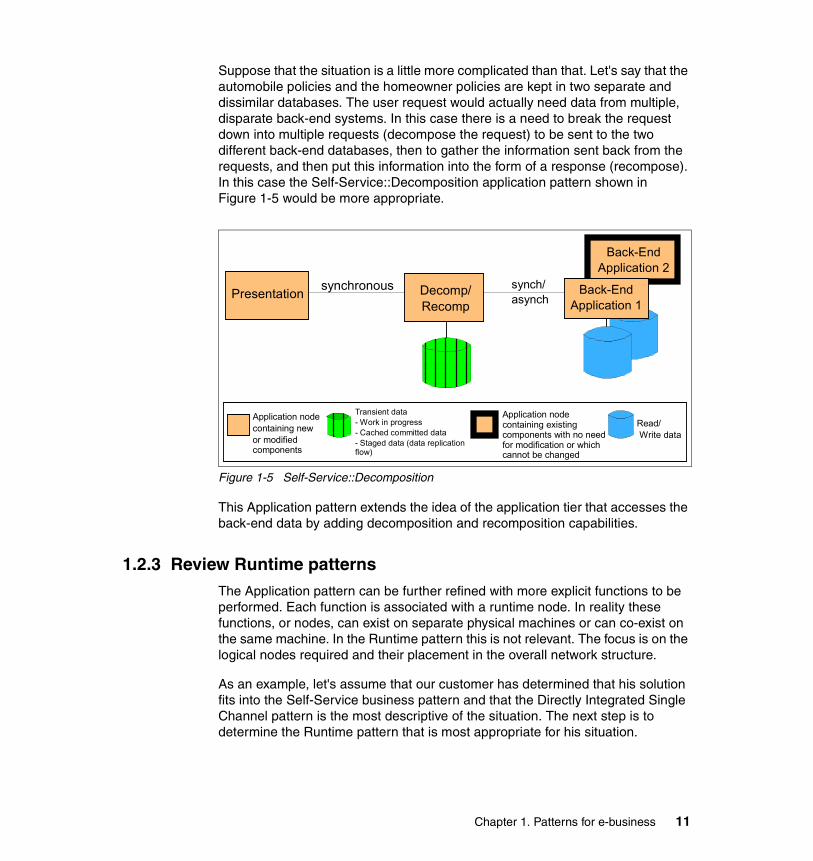
Suppose that the situation is a little more complicated than that. Let's say that the automobile policies and the homeowner policies are kept in two separate and dissimilar databases. The user request would actually need data from multiple, disparate back-end systems. In this case there is a need to break the request down into multiple requests (decompose the request) to be sent to the two different back-end databases, then to gather the information sent back from the requests, and then put this information into the form of a response (recompose). In this case the Self-Service::Decomposition application pattern shown in Figure 1-5 would be more appropriate.
Figure 1-5 Self-Service::Decomposition
This Application pattern extends the idea of the application tier that accesses the back-end data by adding decomposition and recomposition capabilities.
1.2.3 Review Runtime patternsThe Application pattern can be further refined with more explicit functions to be performed. Each function is associated with a runtime node. In reality these functions, or nodes, can exist on separate physical machines or can co-exist on the same machine. In the Runtime pattern this is not relevant. The focus is on the logical nodes required and their placement in the overall network structure.
As an example, let's assume that our customer has determined that his solution fits into the Self-Service business pattern and that the Directly Integrated Single Channel pattern is the most descriptive of the situation. The next step is to determine the Runtime pattern that is most appropriate for his situation.
Presentation synchronous Decomp/Recomp
synch/asynch
Application node containing new or modified components
Application node containing existing components with no need for modification or which cannot be changed
Read/ Write data
Transient data- Work in progress- Cached committed data- Staged data (data replication flow)
Back-EndApplication 1
Back-EndApplication 2
Chapter 1. Patterns for e-business 11

He knows that he will have users on the Internet accessing his business data and he will therefore require a measure of security. Security can be implemented at various layers of the application, but the first line of defense is almost always one or more firewalls that define who and what can cross the physical network boundaries into his company network.
He also needs to determine the functional nodes required to implement the application and security measures. The Runtime pattern shown in Figure 1-6 is one of his options.
Figure 1-6 Directly Integrated Single Channel application pattern::Runtime pattern
By overlaying the Application pattern on the Runtime pattern, you can see the roles that each functional node will fulfill in the application. The presentation and application tiers will be implemented with a Web application server, which combines the functions of an HTTP server and an application server. It handles both static and dynamic Web pages.
Application security is handled by the Web application server through the use of a common central directory and security services node.
Internal NetworkDemilitarized Zone
(DMZ)Outside World
Prot
ocol
Fire
wal
l
Existing Applications
and Data
Dom
ain
Fire
wal
lINTERNET
Public Key Infrastructure
User
Web Application
Server
Domain Name Server
Directory and SecurityServices
Presentation Application Application
Directly Integrated Single Channel application
Application
Existing Applications
and Data
12 Patterns: Service-Oriented Architecture and Web Services

A characteristic that makes this Runtime pattern different from others is the placement of the Web application server between the two firewalls. The Runtime pattern shown in Figure 1-7 is a variation on this. It splits the Web application server into two functional nodes by separating the HTTP server function from the application server. The HTTP server (Web server redirector) serves static Web pages and redirects other requests to the application server. It moves the application server function behind the second firewall, adding further security.
Figure 1-7 Directly Integrated Single Channel application pattern::Runtime pattern: Variation 1
These are just two examples of the possible Runtime patterns available. Each Application pattern will have one or more Runtime patterns defined. These can be modified to suit the customer’s needs. For example, the customer may want to add a load-balancing function and multiple application servers.
Internal NetworkDemilitarized Zone
(DMZ)Outside World
Prot
ocol
Fire
wal
l
Dom
ain
Fire
wal
lINTERNET
Public Key Infrastructure
User
WebServer
Redirector
Domain Name Server
Presentation Application Application
Directly Integrated Single Channel application
Application
Existing Applications
and Data
ApplicationServer
Directory and SecurityServices
Existing Applications
and Data
Chapter 1. Patterns for e-business 13
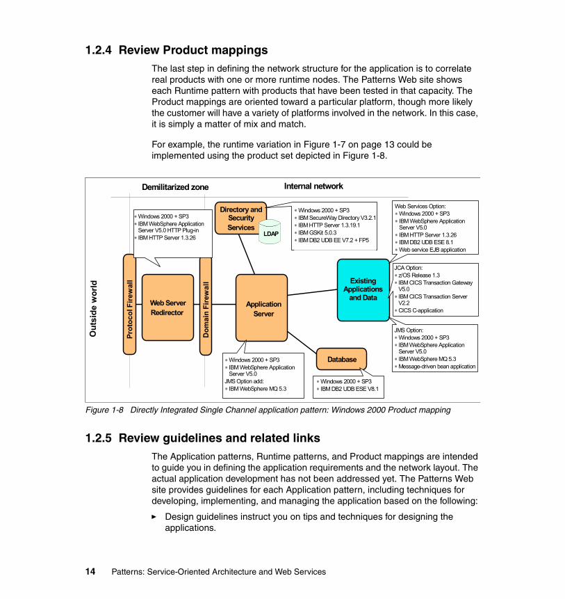
1.2.4 Review Product mappingsThe last step in defining the network structure for the application is to correlate real products with one or more runtime nodes. The Patterns Web site shows each Runtime pattern with products that have been tested in that capacity. The Product mappings are oriented toward a particular platform, though more likely the customer will have a variety of platforms involved in the network. In this case, it is simply a matter of mix and match.
For example, the runtime variation in Figure 1-7 on page 13 could be implemented using the product set depicted in Figure 1-8.
Figure 1-8 Directly Integrated Single Channel application pattern: Windows 2000 Product mapping
1.2.5 Review guidelines and related linksThe Application patterns, Runtime patterns, and Product mappings are intended to guide you in defining the application requirements and the network layout. The actual application development has not been addressed yet. The Patterns Web site provides guidelines for each Application pattern, including techniques for developing, implementing, and managing the application based on the following:
� Design guidelines instruct you on tips and techniques for designing the applications.
Internal networkDemilitarized zone
Out
side
wor
ld
Prot
ocol
Fire
wal
l
Dom
ain
Fire
wal
l
Web ServerRedirector
Windows 2000 + SP3IBM WebSphere Application Server V5.0 HTTP Plug-inIBM HTTP Server 1.3.26
Directory and SecurityServices
LDAP
Application Server
Windows 2000 + SP3IBM SecureWay Directory V3.2.1IBM HTTP Server 1.3.19.1IBM GSKit 5.0.3IBM DB2 UDB EE V7.2 + FP5
Database
Existing Applications
and Data
Windows 2000 + SP3IBM DB2 UDB ESE V8.1
JMS Option:Windows 2000 + SP3IBM WebSphere Application Server V5.0IBM WebSphere MQ 5.3Message-driven bean application
Web Services Option:Windows 2000 + SP3IBM WebSphere Application Server V5.0IBM HTTP Server 1.3.26IBM DB2 UDB ESE 8.1Web service EJB application
JCA Option:z/OS Release 1.3IBM CICS Transaction Gateway V5.0IBM CICS Transaction Server V2.2CICS C-application
Windows 2000 + SP3IBM WebSphere Application Server V5.0
JMS Option add:IBM WebSphere MQ 5.3
14 Patterns: Service-Oriented Architecture and Web Services

� Development guidelines take you through the process of building the application, from the requirements phase all the way through the testing and rollout phases.
� System management guidelines address the day-to-day operational concerns, including security, backup and recovery, application management, and so forth.
� Performance guidelines give information on how to improve the application and system performance.
1.3 SummaryThe IBM Patterns for e-business are a collected set of proven architectures. This repository of assets can be used by companies to facilitate the development of Web-based applications. They help an organization understand and analyze complex business problems and break them down into smaller, more manageable functions that can then be implemented.
Chapter 1. Patterns for e-business 15

16 Patterns: Service-Oriented Architecture and Web Services

Chapter 2. Service-oriented architecture
This chapter provides an introduction to service-oriented architecture. It also introduces Web Services as an implementation of service-oriented architecture (SOA).
In this chapter, we discuss the following topics:
� Overview of service-oriented architecture
� Web services architecture
� Web services and service-oriented architecture
� Enterprise Service Bus
� Where to find more information
2
© Copyright IBM Corp. 2004. All rights reserved. 17

2.1 Overview of service-oriented architectureIn this section we briefly describe the evolution of service-oriented architecture. We then explore the relationship between component-based development and service-oriented architecture and show how components can be the cornerstones of the infrastructure for implementing services.
2.1.1 The business drivers for a new approachWhile IT executives have been facing the challenge of cutting costs and maximizing the utilization of existing technology, at the same time they have to continuously strive to serve customers better, be more competitive, and be more responsive to the business’s strategic priorities.
There are two underlying themes behind all of these pressures: Heterogeneity and change. Most enterprises today contain a range of different systems, applications, and architectures of different ages and technologies. Integrating products from multiple vendors and across different platforms were almost always a nightmare. But we also cannot afford to take a single-vendor approach to IT, because application suites and the supporting infrastructure are so inflexible.
Change is the second theme underlying the questions that today’s IT executives face. Globalization and e-business are accelerating the pace of change. Globalization leads to fierce competition, which leads to shortening product cycles, as companies look to gain advantage over their competition. Customer needs and requirements change more quickly driven by competitive offerings and wealth of product information available over the Internet. In response the cycle of competitive improvements in products and services further accelerates.
Improvements in technology continue to accelerate, feeding the increased pace of changing customer requirements. Business must rapidly adapt to survive, let alone to succeed in today’s dynamic competitive environment, and the IT infrastructure must enable businesses’ ability to adapt.
As a result, business organizations are evolving from the vertical, isolated business divisions of the 1980’s and earlier, to the horizontal business-process-focused structures of the 1980’s and 1990’s, towards the new ecosystem business paradigm. Business services now need to be componentized and distributed. There is a focus on the extended supply chain, enabling customer and partner access to business services. The CBDI Forum Report Business Integration - Drivers and Directions illustrates this evolution of business as shown in Figure 2-1 on page 19. You can access this CBDI report and a related CBDI workshop titled Service Based Approach at:
18 Patterns: Service-Oriented Architecture and Web Services

http://www.cbdiforum.com/
Figure 2-1 The evolution of business
How do I make my IT environment more flexible and responsive to the ever changing business requirements? How can we make those heterogeneous systems and applications communicate as seamlessly as possible? How can we achieve the business objective without bankrupting the enterprise?
The IT answers/enablers have been evolving in parallel with this evolution of business, as shown in Figure 2-2. Currently many IT executives and professionals alike believe that now we are getting really close to providing a satisfactory answer with service-oriented architecture.
Figure 2-2 The evolution of architecture
In order to alleviate the problems of heterogeneity, interoperability and ever changing requirements, such an architecture should provide a platform for building application services with the following characteristics:
� Loosely coupled
� Location transparent
� Protocol independent
Vertical1980s and Earlier
Horizontal1980s and 1990s
EcosystemThe New World
Serv
ices
Com
pone
nts
Dis
tribu
ted
Obj
ects
N-T
ier
3-Ti
er
Clie
nt/S
erve
r
Stru
ctur
ed
Mon
olot
hs
Chapter 2. Service-oriented architecture 19

Based on such a service-oriented architecture, a service consumer does not even have to care about a particular service it is communicating with because the underlying infrastructure, or service “bus”, will make an appropriate choice on behalf of the consumer. The infrastructure hides as many technicalities as possible from a requestor. Particularly technical specificities from different implementation technologies such as J2EE or .NET should not affect the SOA users. We should also be able to reconsider and substitute a “better” service implementation if one is available, and with better quality of service characteristics.
2.1.2 Service-oriented architecture as a solutionEver since the “software crisis” prompted the beginnings of software engineering, the IT industry has been struggling to find solutions to solve the above problems. Throughout the years, the following short list of core technology advancements have brought us to where we are today. We will briefly discuss those core technologies and our focus will be on how such technologies help resolve IT problems.
Object-oriented analysis and designLarman describes the essence of the object-oriented analysis and design as considering “a problem domain and logical solution from the perspective of objects (things, concepts, or entities)” in Applying UML and Patterns - An Introduction to Object-Oriented Analysis and Design. Jacobson, et al, define these objects as being “characterized by a number of operations and a state that remembers the effects of these operations” in Object-Oriented Software Engineering: A Use Case Driven Approach.
In object-oriented analysis, such objects are identified and described in the problem domain, while in object-oriented design, they are transitioned into logical software objects that will ultimately be implemented in a object-oriented programming language.
With object-oriented analysis and design, certain aspects of the object (or group of objects) can be encapsulated to simplify the analysis of complex business scenarios. Certain characteristics of the object(s) can also be abstracted so that only the important or essential aspects are captured, in order to reduce complexity.
Component-based designComponent-based design is not a new technology. It is naturally evolved from the object paradigm. In the early days of object-oriented analysis and design, fine-grained objects were marked as a mechanism to provide “reuse”, but those objects are at too low a level of granularity and the there are no standards in
20 Patterns: Service-Oriented Architecture and Web Services

place to make widespread reuse practical. Coarse-grained components have become more and more a target for reuse in application development and system integration. These coarse-grained components provide certain well defined functionality from a cohesive set of finer-grained objects. In this way, packaged solution suites can also be encapsulated as such “components”.
Once the organization achieves a higher level of architectural maturity based on distinctly separate functional components, the applications that support the business can be partitioned into a set of increasingly larger grained components. Components can be seen as the mechanism to package, manage and expose services. They can use a set of technologies in concert: Large-grained enterprise components, that implement business-level use-cases, can be implemented using newer object-oriented software development in combination with legacy systems.
Service-oriented designIn Component-Based Development for Enterprise Systems, Allen includes the notion of services, describing a component as “an executable unit of code that provides physical black-box encapsulation of related services. Its service can only be accessed through a consistent, published interface that includes an interaction standard. A component must be capable of being connected to other components (through a communications interface) to a larger group”.
A service is generally implemented as a course-grained, discoverable software entity that exists as a single instance and interacts with applications and other services through a loosely coupled, message-based communication model. Figure 2-3 on page 22 shows important service-oriented terminology:
� Services: Logical entities, the contracts defined by one or more published interfaces.
� Service provider: The software entity that implements a service specification.
� Service consumer (or requestor): The software entity that calls a service provider. Traditionally, this is termed a “client”. A service consumer can be an end-user application or another service.
� Service locator: A specific kind of service provider that acts as a registry and allows for the lookup of service provider interfaces and service locations.
� Service broker: A specific kind of service provider that can pass on service requests to one or more additional service providers.
Chapter 2. Service-oriented architecture 21

Figure 2-3 Service-oriented terminology
Interface-based designIn both component and service development, the design of the interfaces is done such that a software entity implements and exposes a key part of its definition. Therefore, the notion and concept of “interface” is key to successful design in both component-based and service-oriented systems. The following are some key interface-related definitions:
� Interface: Defines a set of public method signatures, logically grouped but providing no implementation. An interface defines a contract between the requestor and provider of a service. Any implementation of an interface must provide all methods.
� Published interface: An interface that is uniquely identifiable and made available through a registry for clients to dynamically discover.
� Public interface: An interface that is available for clients to use but is not published, thus requiring static knowledge on the part of the client.
� Dual interface: Frequently interfaces are developed as pairs such that one interface depends on another; for example, a client must implement an interface to call a requestor because the client interface provides some callback mechanism.
Figure 2-4 on page 23 shows the UML definition of a customer relationship management (CRM) service, represented as a UML component, that implements the interfaces AccountManagement, ContactManagement, and SystemsManagement. Only the first two of these are published interfaces, although the latter is a public interface. Note that the SystemsManagement
Applications or Services Services
ServiceLocator
ServiceBroker
ServiceProvider
ServiceConsumer
22 Patterns: Service-Oriented Architecture and Web Services

interface and ManagementService interface form a dual interface. The CRM service can implement any number of such interfaces, and it is this ability of a service (or component) to behave in multiple ways depending on the client that allows for great flexibility in the implementation of behavior. It is even possible to provide different or additional services to specific classes of clients. In some run-time environments such a capability is also used to support different versions of the same interface on a single component or service.
Figure 2-4 Implemented services
Layered application architecturesAs mentioned before, object-oriented technology and languages are great ways to implement components. While components are the best way to implement services, though one has to understand that a good component-based application does not necessarily make an good service-oriented application. A great opportunity exists to leverage component developers and existing components, once the role played by services in application architecture is understood. The key to making this transition is to realize that a service-oriented approach implies an additional application architecture layer. Figure 2-5 on page 24 demonstrates how technology layers can be applied to application architecture to provide more coarse-grained implementations as one gets closer to the consumers of the application. The term coined to refer to this part of the system is “the application edge,” reflecting the fact that a service is a great way to expose an external view of a system, with internal reuse and composition using traditional component design.
AccountManagement{published}
ContactManagement{published}
Systems Management
ManagementService
CRM
Chapter 2. Service-oriented architecture 23

Figure 2-5 Application implementation layers: Services, components, objects
2.1.3 A closer look at service-oriented architectureService-oriented architecture presents an approach for building distributed systems that deliver application functionality as services to either end-user applications or other services. It is comprised of elements that can be categorized into functional and quality of service. Figure 2-6 on page 25 shows the architectural stack and the elements that might be observed in a service-oriented architecture.
Component Layer
Service Layer
Object/Class Layer
Note: Service-oriented architecture stacks can be a contentious issue, with several different stacks being put forward by various proponents. Our stack is not being positioned as the services stack. It is just presented as useful framework for structuring the SOA discussion in the rest of the publication.
24 Patterns: Service-Oriented Architecture and Web Services

Figure 2-6 Elements of a service-oriented architecture
The architectural stack is divided into two halves, with the left half addressing the functional aspects of the architecture and the right half addressing the quality of service aspects. These elements are described in detail as follows:
� Functional aspects include:
– Transport is the mechanism used to move service requests from the service consumer to the service provider, and service responses from the service provider to the service consumer.
– Service Communication Protocol is an agreed mechanism that the service provider and the service consumer use to communicate what is being requested and what is being returned.
– Service Description is an agreed schema for describing what the service is, how it should be invoked, and what data is required to invoke the service successfully.
– Service describes an actual service that is made available for use.
– Business Process is a collection of services, invoked in a particular sequence with a particular set of rules, to meet a business requirement. Note that a business process could be considered a service in its own right, which leads to the idea that business processes may be composed of services of different granularities.
– The Service Registry is a repository of service and data descriptions which may be used by service providers to publish their services, and service
Transport
Business Process
Service Communication Protocol
Service Description
Service
Serv
ice
Reg
istry
Polic
y
Secu
rity
Tran
sact
ion
Man
agem
ent
Functions Quality of Service
Chapter 2. Service-oriented architecture 25

consumers to discover or find available services. The service registry may provide other functions to services that require a centralized repository.
� Quality of service aspects include:
– Policy is a set of conditions or rules under which a service provider makes the service available to consumers. There are aspects of policy which are functional, and aspects which relate to quality of service; therefore we have the policy function in both functional and quality of service areas.
– Security is the set of rules that might be applied to the identification, authorization, and access control of service consumers invoking services.
– Transaction is the set of attributes that might be applied to a group of services to deliver a consistent result. For example, if a group of three services are to be used to complete a business function, all must complete or none must complete.
– Management is the set of attributes that might be applied to managing the services provided or consumed.
SOA collaborationsFigure 2-7 shows the collaborations in a service-oriented architecture. The collaborations follows the “find, bind and invoke” paradigm where a service consumer performs dynamic service location by querying the service registry for a service that matches its criteria. If the service exists, the registry provides the consumer with the interface contract and the endpoint address for the service. The following diagram illustrates the entities in an service-oriented architecture that collaborate to support the “find, bind and invoke” paradigm.
Figure 2-7 Collaborations in a service-oriented architecture
ServiceProvider
Bind and InvokeServiceConsumer
ServiceRegistry
Find Publish
ServiceDescription
Service
ServiceDescription
26 Patterns: Service-Oriented Architecture and Web Services

The roles in a service-oriented architecture are:
� Service consumer: The service consumer is an application, a software module or another service that requires a service. It initiates the enquiry of the service in the registry, binds to the service over a transport, and executes the service function. The service consumer executes the service according to the interface contract.
� Service provider: The service provider is a network-addressable entity that accepts and executes requests from consumers. It publishes its services and interface contract to the service registry so that the service consumer can discover and access the service.
� Service registry: A service registry is the enabler for service discovery. It contains a repository of available services and allows for the lookup of service provider interfaces to interested service consumers.
Each entity in the service-oriented architecture can play one (or more) of the three roles of service provider, consumer and registry.
The operations in a service-oriented architecture are:
� Publish: To be accessible, a service description must be published so that it can be discovered and invoked by a service consumer.
� Find: A service requestor locates a service by querying the service registry for a service that meets its criteria.
� Bind and invoke: After retrieving the service description, the service consumer proceeds to invoke the service according to the information in the service description.
The artifacts in a service-oriented architecture are:
� Service: A service that is made available for use through a published interface that allows it to be invoked by the service consumer.
� Service description: A service description specifies the way a service consumer will interact with the service provider. It specifies the format of the request and response from the service. This description may specify a set of preconditions, post conditions and/or quality of service (QoS) levels.
In addition to dynamic service discovery and definition of a service interface contract, a service-oriented architecture has the following characteristics:
� Services are self-contained and modular.
� Services support interoperability.
� Services are loosely coupled.
� Services are location-transparent.
Chapter 2. Service-oriented architecture 27

� Services are composite modules, comprised of components.
These characteristics are also central to fulfilling the requirements for an e-business on demand™ operational environment, as defined in Chapter 10, “e-business on demand and Service-oriented architecture” on page 301.
Finally, service-oriented architecture is not a new notion. As shown in Figure 2-8, examples of technologies that are at least partly service-oriented include CORBA, DCOM and J2EE. Early adopters of the service-oriented architecture approach have also successfully created their own service-oriented enterprise architectures based on messaging systems such as IBM WebSphere MQ. Most recently, the SOA arena has expanded to include the World Wide Web (WWW) and Web Services.
Figure 2-8 Different implementations of service-oriented architecture
Services in the context of SOAIn service-oriented architecture, services map to the business functions that are identified during business process analysis. The services may be fine- or coarse-grained depending upon the business processes. Each service has a well-defined interface that allows it to be published, discovered and invoked. An enterprise can choose to publish its services externally to business partners or internally within the organisation. A service can also be composed from other services.
Services vs. componentsA service is a coarse-grained processing unit that consumes and produces sets of objects passed-by-value. It is not the same as an object in programming language terms. Instead, it is perhaps closer to the concept of a business
Service Oriented Architecture (SOA)
WorldWideWeb
(WWW)
WebServices
CORBA
DCOM
J2EE
Others
Distributed Systems Architecture
28 Patterns: Service-Oriented Architecture and Web Services

transaction such as a CICS® or IMS™ transaction than to a remote CORBA object.
A service consists of a collection of components that work in concert to deliver the business function that the service represents. Thus, in comparison, components are finer-grained than services. In addition, while a service maps to a business function, a component typically maps to business entities and the business rules that operate on them. As an example, let us look at the Purchase Order component model for the WS-I Supply Chain Management sample, shown in Figure 2-9.
Figure 2-9 Purchase Order component model
In a component-based design, components are created to closely match business entities (such as Customer, Purchase Order, Order Item) and encapsulate the behavior that matches the entities’ expected behavior.
For example, the Purchase Order component provides functions to obtain information about the list of products ordered and the total amount of the order; the Item component provides functions to obtain information about the quantity and price of the product ordered. The implementation of each component is encapsulated behind the interface. So, a user of the Purchase Order component does not know the schema of the Purchase Order table and the algorithm for calculating tax, rebates and/or discounts on the total amount of the order.
In a service-oriented design, services are not designed based on business entities. Instead, each service is a holistic unit that manages operations across a set of business entities. For example, a customer service will respond to any request from any other system or service that needs to access customer information. The customer service can process a request to update customer information; add, update, delete investment portfolios; and enquire about the
+ getID ( )+ setID ( )+ getQty ( )+ setQty ( )+ getPrice ( )+ setPrice ( )
Item
ItemList
+ getItem ( )+ setValue ( )
CustomerReferenceType
+ getValue ( )+ setValue ( )
PurchOrdType
+ getOrderNum ( )+ setOrderNum ( )+ getCustomerRef ( )+ setCustomerRef ( )+ getItems ( )+ setItems ( )+ getTotal ( )+ setTotal ( )
*
*1
1
Chapter 2. Service-oriented architecture 29

customer’s order history. The customer service owns all the data related to the customers it is managing and is capable of making other service inquiries on behalf of the calling party in order to provide a unified customer service view. This means a service is a manager object that creates and manages its set components.
2.1.4 Service-oriented architecture benefitsAs discussed earlier, businesses are dealing with two fundamental concerns: The ability to change quickly, and the need to reduce costs. To remain competitive businesses must adapt quickly to internal factors such as acquisitions and restructuring, or external factors like competitive forces and customer requirements. Cost-effective, flexible IT infrastructure is need to support the business.
With a service-oriented architecture, we can realize several benefits to help organizations succeed in the dynamic business landscape of today:
� Leverage existing assets.
SOAs provide a layer of abstraction that enables an organization to continue leveraging its investment in IT by wrapping these existing assets as services that provide business functions. Organizations potentially can continue getting value out of existing resources instead of having to rebuild from scratch.
� Easier to integrate and manage complexity.
The integration point in a service-oriented architecture is the service specification and not the implementation. This provides implementation transparency and minimizes the impact when infrastructure and implementation changes occur. By providing a service specification in front of existing resources and assets built on disparate systems, integration becomes more manageable since complexities are isolated. This becomes even more important as more businesses work together to provide the value chain.
� More responsive and faster time-to-market.
The ability to compose new services out of existing ones provides a distinct advantage to an organization that has to be agile to respond to demanding business needs. Leveraging existing components and services reduces the time needed to go through the software development life cycle of gathering requirements, performing design, development and testing. This leads to rapid development of new business services and allows an organization to respond quickly to changes and reduce the time-to-market.
� Reduce cost and increase reuse.
30 Patterns: Service-Oriented Architecture and Web Services

With core business services exposed in a loosely coupled manner, they can be more easily used and combined based on business needs. This means less duplication of resources, more potential for reuse, and lower costs.
� Be ready for what lies ahead.
SOAs allows businesses be ready for the future. Business processes which comprise of a series of business services can be more easily created, changed and managed to meet the needs of the time. SOA provides the flexibility and responsiveness that is critical to businesses to survive and thrive.
Service-oriented architecture is by no means a silver bullet, and migration to SOA is not an easy task. Rather than migrating the whole enterprise to a service-oriented architecture overnight, the recommended approach is to migrate an appropriate subset of business functions as the business need arises or is anticipated.
2.2 Web services architectureWeb services are a relatively new technology that have received wide acceptance as an important implementation of service-oriented architecture. This is because Web services provides a distributed computing approach for integrating extremely heterogeneous applications over the Internet. The Web service specifications are completely independent of programming language, operating system, and hardware to promote loose coupling between the service consumer and provider. The technology is based on open technologies such as:
� eXtensible Markup Language (XML)
� Simple Object Access Protocol (SOAP)
� Universal Description, Discovery and Integration (UDDI)
� Web Services Description Language (WSDL)
Using open standards provides broad interoperability among different vendor solutions. These principles mean that companies can implement Web services without having any knowledge of the service consumers, and vice versa. This facilitates just-in-time integration and allows businesses to establish new partnership easily and dynamically.
2.2.1 What Web services areThe W3C’s Web Services Architecture Working Group has jointly come to agreement on the following working definition of a Web service:
Chapter 2. Service-oriented architecture 31

“A Web service is a software application identified by a URI, whose interfaces and bindings are capable of being defined, described, and discovered as XML artifacts. A Web service supports direct interactions with other software agents using XML-based messages exchanged via Internet-based protocols.”
Basic Web services combine the power of two ubiquitous technologies: XML, the universal data description language; and the HTTP transport protocol widely supported by browser and Web servers.
Web services = XML + transport protocol (such as HTTP)
Some of the key features of Web services are the following:
� Web services are self-contained.
On the client side, no additional software is required. A programming language with XML and HTTP client support, for example, is enough to get you started. On the server side, merely a Web server and a servlet engine are required. It is possible to Web service enable an existing application without writing a single line of code.
� Web services are self-describing.
Neither the client nor the server knows or cares about anything besides the format and content of request and response messages (loosely coupled application integration).
The definition of the message format travels with the message. No external metadata repositories or code generation tools are required.
� Web services are modular.
Web services are a technology for deploying and providing access to business functions over the Web; J2EE, CORBA, and other standards are technologies for implementing these Web services.
� Web services can be published, located, and invoked across the Web.
The standards required to do so are:
– Simple Object Access Protocol (SOAP), also known as service-oriented architecture protocol, an XML-based RPC and messaging protocol
– Web Service Description Language (WSDL), a descriptive interface and protocol binding language
– Universal Description, Discovery, and Integration (UDDI), a registry mechanism that can be used to look up Web service descriptions
32 Patterns: Service-Oriented Architecture and Web Services

� Web services are language independent and interoperable.
The interaction between a service provider and a service requester is designed to be completely platform and language independent. This interaction requires a WSDL document to define the interface and describe the service, along with a network protocol (usually HTTP). Because the service provider and the service requester have no idea what platforms or languages the other is using, interoperability is a given.
� Web services are inherently open and standards based.
XML and HTTP are the technical foundation for Web services. A large part of the Web service technology has been built using open source projects. Therefore, vendor independence and interoperability are realistic goals.
� Web services are dynamic.
Dynamic e-business can become a reality using Web services because, with UDDI and WSDL, the Web service description and discovery can be automated.
� Web services are composable.
Simple Web services can be aggregated to more complex ones, either using workflow techniques or by calling lower-layer Web services from a Web service implementation.
Figure 2-10 shows a typical Web service collaboration that is based on the SOA model shown previously in Figure 2-7 on page 26.
Figure 2-10 Web service collaboration
2a. Query Service
2b. Returns theservice contract
3a. Invokeserviceaccordingto contract
3b. RequestreachesWebServer
3c. Requestreachesserviceprovider
WebServer
1. Publish service
ServiceProvider
PublicUDDI
InternetServiceConsumer
Chapter 2. Service-oriented architecture 33

2.2.2 Web service interoperabilityWeb services are one of the rising stars in the IT world, supporting the integration of existing systems and sharing of resources and data, both within and outside an organization. They are a relatively new technology, with Web services standards continuing to be refined and developed.
For the key promise of Web services interoperability to work, standards need to be carefully managed. In addition, guidance in interpretation and implementation of standards is essential to facilitate adoption of a technology. The Web Services Interoperability Organization has an important role in this area, as a standards integrator to help Web services advance in a structured and coherent manner.
IBM’s commitment in this direction includes active participation in WS-I standards development, and early delivery of WS-I compliance in runtime and development products. In this publication, we place considerable emphasis on WS-I standards and guidelines as an enabler for Web services interoperability.
Web Services Interoperability OrganizationWeb Services Interoperability Organization (WS-I) is an open, industry consortium of about 150 companies, representing diverse industries such as automotive, consumer packaged goods, finance, government, insurance, media, telecommunications, travel and the computer industry. It is chartered to:
� Promote Web services interoperability across platforms, operating systems, and programming languages with the use of generic protocols for interoperable exchange of messages between services.
� Encourage Web services adoption.
� Accelerate deployment by providing guidance, best practices and other resources for developing interoperable Web services.
WS-I, as a standards integrator, supports the relationships with standards bodies who own specifications and fosters communication and cooperation with industry consortia and other organizations, as shown in Figure 2-11 on page 35.
34 Patterns: Service-Oriented Architecture and Web Services

Figure 2-11 WS-I, standards and industry
WS-I has a set of deliverables to assist in the development and deployment of Web services, including its profile of interoperable Web services. A profile is defined in the WS-I Glossary as follows:
“A collection of requirements to support interoperability. WS-I will deliver a collection of profiles that support technical requirements and specifications to achieve interoperable Web Services.”
It includes the following deliverables:
� Profile Specification
This includes a list of non-proprietary Web services-related specifications at certain version levels, plus a list of clarifications and restrictions on those specifications to facilitate the development of interoperable Web services.
� Use Cases and Usage Scenarios
These capture the business and technical requirements, respectively, for the use of Web services. These requirements reflect the classes of real-world requirements supporting Web services solutions, and provide a framework to demonstrate the guidelines described in WS-I Profiles.
Standards Bodies
Standards,Specifications,Protocols
Requirements
ImplementationGuidance, BestPractices
Requirements
Businesses, Industry Consortia, Developers, End Users
Chapter 2. Service-oriented architecture 35

� Sample Applications
These demonstrate the implementation of applications that are built from Web services Usage Scenarios and Use Cases, and that conform to a given set of Profiles. Implementations of the same Sample Application on multiple platforms, using different languages and development tools, allow WS-I to demonstrate interoperability in action, and to provide readily usable resources for the Web services practitioner.
� Testing Tools
These are used to monitor and analyze interactions with a Web service to determine whether or not the messages exchanged conform to WS-I Profile guidelines.
For more information on WS-I, refer to:
http://www.ws-i.org/
WS-I Basic Profile 1.0WS-I has delivered its first profile of interoperable Web services called WS-I Basic Profile 1.0, which focuses on the core foundation technologies upon which Web services are based: HTTP, SOAP, WSDL, UDDI, XML and XML Schema. Basic Profile 1.0 was unanimously approved on July 22, 2003, by the WS-I board of directors and members.
The WS-I Basic Profile 1.0 - Profile Specification consists of the following non-proprietary Web services related specifications:
� SOAP 1.1� WSDL 1.1� UDDI 2.0� XML 1.0 (Second Edition)� XML Schema Part 1: Structures� XML Schema Part 2: Datatypes� RFC2246: The Transport Layer Security Protocol Version 1.0� RFC2459: Internet X.509 Public Key Infrastructure Certificate and CRL
Profile� RFC2616: HyperText Transfer Protocol 1.1� RFC2818: HTTP over TLS� RFC2965: HTTP State Management Mechanism� The Secure Sockets Layer Protocol Version 3.0
36 Patterns: Service-Oriented Architecture and Web Services

The WS-I Basic Profile 1.0 - Usage Scenario consists of three usage scenarios, where a usage scenario is a design pattern of interacting entities including actor, roles and message exchange patterns:
� One-way Usage Scenario
– Simplest usage scenario, where the message exchange is one-way, with a Consumer sending a request to a Provider
– Should be used only where loss of information can be tolerated
� Synchronous request/response Usage Scenario
Most commonly used usage scenario where a Consumer sends a request to a Provider, who processes the request and sends back a response
� Basic callback Usage Scenario
– Used to simulate an asynchronous operation using synchronous operations
– Composed of two synchronous request/response usage scenarios, one initiated by a Consumer and the other by a Producer
A mapping of the usage scenarios to the clarifications and restrictions of the profile specifications is done via a Web services usage stack to guide Web services developers.
The WS-I Supply Chain Management sample application depicts an application for a fictitious consumer electronics retailer. We will use the WS-I sample to illustrate concepts and scenarios throughout the publication.
See also the following IBM developerWorks® articles:
� First look at the WS-I Basic Profile 1.0, available at:
http://www.ibm.com/developerworks/webservices/library/ws-basicprof.html
� First look at the WS-I Usage Scenarios, available at:
http://www.ibm.com/developerworks/webservices/library/ws-iuse/
� Preview of WS-I sample application, available at:
http://www.ibm.com/developerworks/webservices/library/ws-wsisamp/
2.3 Web services and service-oriented architectureWeb services are a technology that is well suited to implementing a service-oriented architecture. In essence, Web services are self-describing and modular applications that expose business logic as services that can be published, discovered, and invoked over the Internet. Based on XML standards,
Chapter 2. Service-oriented architecture 37

Web services can be developed as loosely coupled application components using any programming language, any protocol, or any platform. This facilitates the delivery of business applications as a service accessible to anyone, anytime, at any location, and using any platform.
It is important to point out that Web services are not the only technology that can be used to implement a service-oriented architecture. Many examples of organizations who have successfully implemented service-oriented architectures using other technologies can be found. Web services have also been used by others to implement architectures that are not service-oriented. In this publication, however, our focus is on using Web services to implement an SOA.
For more information on SOA and Web services, refer to:
http://www.ibm.com/software/solutions/webservices/resources.html
This Web site provides a collection of IBM resources on this topic.
2.4 Enterprise Service BusWeb services based technologies are becoming more widely used in enterprise application development and integration. One of the critical issues arising now is finding more efficient and effective ways of designing, developing and deploying Web services based business systems; more importantly, moving beyond the basic point-to-point Web services communications to broader application of these technologies to enterprise-level business processes. In this context, the Enterprise Service Bus (ESB) model is emerging as a major step forward in the evolution of Web services and service-oriented architecture.
2.4.1 Basic Web servicesBasic (point-to-point SOAP/HTTP) Web services provide a solid foundation for implementing a service-oriented architecture, but there are important considerations that affect their flexibility and maintainability in enterprise-scale architectures.
First, the point-to-point nature of basic Web services means that service consumers often need to be modified whenever the service provider interface changes. This is often not a problem on a small scale, but in large enterprises it could mean changes to many client applications. It can also become increasingly difficult to make such changes to legacy clients.
Second, you can end up with an architecture that is fragile and inflexible when large numbers of service consumers and providers communicate using point-to-point “spaghetti” style connections.
38 Patterns: Service-Oriented Architecture and Web Services

Last, basic Web services require that each consumer has a suitable protocol adapter for each provider it needs to use. Having to deploy multiple protocol adapters across many client applications adds to cost and maintainability issues.
Let us look at how the Enterprise Service Bus approach addresses these issues.
2.4.2 What an Enterprise Service Bus isThe Enterprise Service Bus concept is not a product, but an architectural best practice for implementing a service-oriented architecture. As shown in Figure 2-12, it establishes an enterprise-class messaging bus that combines messaging infrastructure with message transformation and content-based routing in a layer of integration logic between service consumers and providers.
Figure 2-12 Enterprise Service Bus
The main aim of the Enterprise Service Bus is to provide virtualization of the enterprise resources, allowing the business logic of the enterprise to be developed and managed independently of the infrastructure, network, and provision of those business services. Resources in the ESB are modelled as services that offer one or more business operations.
Implementing an Enterprise Service Bus requires an integrated set of middleware services that support the following architecture styles:
� Services oriented architectures, where distributed applications are composed of granular re-usable services with well-defined, published and standards-compliant interfaces
� Message-driven architectures, where applications send messages through the ESB to receiving applications
� Event-driven architectures, where applications generate and consume messages independently of one another
Enterprise Service BusTransforms message formats between consumer and providerRoutes requests to correct service providerConverts transport protocols between consumer and provider
Service Consumers Service Providers
Chapter 2. Service-oriented architecture 39
The middleware services provided by an Enterprise Service Bus need to include:
� Communication middleware supporting a variety of communication paradigms (such as synchronous, asynchronous, request/reply, one-way, call-back), qualities of service (such as security, guaranteed delivery, performance, transactional), APIs, platforms, and standard protocols
� A mechanism for injecting intelligent processing of in-flight service requests and responses within the network
� Standard-based tools for enabling rapid integration of services
� Management system for loosely-coupled applications and their interactions
2.4.3 The IBM visionAs shown in Figure 2-13 on page 41, IBM is extending its Web services and service-oriented architecture vision with an Enterprise Service Bus architecture that provides a standards-based integration layer using the intermediary/mediator pattern.
40 Patterns: Service-Oriented Architecture and Web Services

Figure 2-13 Enterprise Service Bus conceptual model
Intelligent mediations are invoked between service consumer and provider that facilitate the selection of services, logging, usage metrics, and so on. These mediations can be configured by policies that define consumer and provider capabilities and requirements. For example, if a provider expects encrypted messages, the requester mediation should include such capability. If a requester only supports SOAP/HTTP, an intermediary should be added to convert to SOAP/JMS.
PortalService
B2BInteractions
Enterprise Service Bus (Mediation):Transform, Route, Notify, Augment
Workflow &Compensation
EISAdapter
EJBScriptJ2C
DataAccess
Chapter 2. Service-oriented architecture 41

The other main components in this model include WSDL services that are generated using tools, or implemented by programmers. These include:
� A workflow and compensation system that executes business processes, or workflows. Activity nodes in a business process typically map to invoking an operation on a Web service. This component supports J2EE transactions and a compensation model for long duration business processes.
� Enterprise Information System (EIS) adaptors based on the J2EE Connector Architecture allow integration with legacy systems.
� XML database access through a WSDL interface.
� Custom-built WSDL services implemented by programmers using the J2EE programming model.
The Enterprise Service Bus supports multiple protocols for communication between services, including SOAP, HTTP, JMS, RMI/IIOP, and so on.
The Enterprise Service Bus can be implemented today using currently available IBM WebSphere products, for example:
� IBM WebSphere Application Server V5.1 provides a J2EE runtime environment for services using SOAP over HTTP or JMS, and J2EE Connectors for EIS integration.
� IBM WebSphere MQ provides the JMS messaging infrastructure.
� The Web Services Gateway with IBM WebSphere Application Server Network Deployment V5.1 provides SOAP message routing, transformation, and protocol conversion. The UDDI Registry provides dynamic service discovery.
� IBM WebSphere Application Server Enterprise V5.0 provides the Process Choreographer for service orchestration or workflow.
� IBM DB2® XML Extender enables database access via the ESB.
� IBM WebSphere Portal allows integrated, personalized end-user access to business services.
You can also expect a strong focus on Enterprise Service Bus capabilities in future releases of WebSphere family products.
Note: Implementation of an Enterprise Service Bus is beyond the scope of this publication. The intention here is just to provide an introduction to this important architectural best practice.
42 Patterns: Service-Oriented Architecture and Web Services

2.5 Where to find more informationFor more information on topics discussed in this chapter, see:
� The following IBM developerWorks articles:
– First look at the WS-I Basic Profile 1.0, available at:
http://www.ibm.com/developerworks/webservices/library/ws-basicprof.html
– First look at the WS-I Usage Scenarios, available at:
http://www.ibm.com/developerworks/webservices/library/ws-iuse/
– Preview of WS-I sample application, available at:
http://www.ibm.com/developerworks/webservices/library/ws-wsisamp/
– Using Service-Oriented Architecture and Component-Based Development to Build Web Service Applications, available at:
http://www.ibm.com/developerworks/rational/library/510.html
� W3C Working Group Note, Web Services Architecture, available at:
http://www.w3.org/TR/2004/NOTE-ws-arch-20040211/
� Craig Larman, Applying UML and Patterns: An Introduction to Object-Oriented Analysis and Design and the Unified Process, 2nd Ed., Prentice Hall, 2001
� Ivar Jacobson, Magnus Christerson, Patrik Jonsson, Gunnar Overgaard, Object-Oriented Software Engineering: A Use Case Driven Approach, Addison-Wesley, 1992
� Paul Allen, Component-Based Development for Enterprise Systems, Cambridge University Press, 1998
Chapter 2. Service-oriented architecture 43

44 Patterns: Service-Oriented Architecture and Web Services

Chapter 3. Service-oriented architecture and Patterns for e-business
In this chapter we introduce how the IBM Patterns for e-business compliment the service-oriented architecture (SOA) approach. We look at how SOA applies to Patterns, in particular the Self-Service and Extended Enterprise business patterns, the Application Integration pattern, and the associated Application patterns, Runtime patterns, and Product mappings.
A detailed description of the service-oriented architecture approach can be found in Chapter 4, “Service-oriented architecture approach” on page 79.
3
© Copyright IBM Corp. 2004. All rights reserved. 45
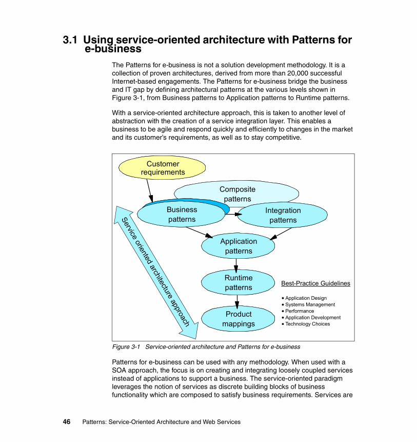
3.1 Using service-oriented architecture with Patterns for e-business
The Patterns for e-business is not a solution development methodology. It is a collection of proven architectures, derived from more than 20,000 successful Internet-based engagements. The Patterns for e-business bridge the business and IT gap by defining architectural patterns at the various levels shown in Figure 3-1, from Business patterns to Application patterns to Runtime patterns.
With a service-oriented architecture approach, this is taken to another level of abstraction with the creation of a service integration layer. This enables a business to be agile and respond quickly and efficiently to changes in the market and its customer’s requirements, as well as to stay competitive.
Figure 3-1 Service-oriented architecture and Patterns for e-business
Patterns for e-business can be used with any methodology. When used with a SOA approach, the focus is on creating and integrating loosely coupled services instead of applications to support a business. The service-oriented paradigm leverages the notion of services as discrete building blocks of business functionality which are composed to satisfy business requirements. Services are
Best-Practice Guidelines
Application DesignSystems ManagementPerformanceApplication DevelopmentTechnology Choices
Customer requirements
Productmappings
Runtimepatterns
Applicationpatterns
Compositepatterns
Businesspatterns
IntegrationpatternsService oriented architecture approach
46 Patterns: Service-Oriented Architecture and Web Services

self-contained and modular, while applications tend to be too coarse-grained to be reused effectively, and are often too inflexible to be leveraged within an enterprise or an extended enterprise.
The existing Business, Integration, Application and Runtime patterns are consistent with the SOA approach. The business problem will drive the identification of the appropriate Business, Integration, Application and Runtime patterns involved in a potential solution. Runtime patterns that involve two or more middleware nodes connecting logical application tiers will have additional communication options (and hence Product mappings) between the tiers with the use of services in a SOA.
One candidate for a new Composite pattern in the context of services is the Value-Chain. Essentially, the Value-Chain consists of a Self-Service business pattern and a set of recurring (often twice recurring) Extended Enterprise business patterns that can be combined to provide value to a chain of business partners. This end-to-end composite pattern is prevalent in any Value-Net.
3.2 Self-Service business patternThe Self-Service business pattern essentially captures the direct interactions between users and an enterprise, which range from simple information access to complex updates involving core enterprise systems and data. This blends in nicely with a service-oriented architecture which fundamentally comprises of service consumers and service providers. Users such as customers, business partners, stockholders and employees are service consumers, while the enterprise is the service provider.
The Self-Service::Directly Integrated Single Channel application pattern, for example, provides a user access channel to presentation logic running in the presentation tier. The presentation tier can request or consume services provided on the Web application tier. The Web application tier in turn can consume services provided on the back-end or enterprise tier, as shown in Figure 3-2 on page 48.
We use Application Integration patterns to examine these intra-enterprise service-oriented connections in more detail in 3.4, “Application Integration pattern” on page 49.
Chapter 3. Service-oriented architecture and Patterns for e-business 47

Figure 3-2 Self-Service::Directly Integrated Single Channel application pattern
3.3 Extended Enterprise business patternThe Extended Enterprise business pattern addresses interactions and collaborations between business processes in separate enterprises. The interactions and collaborations are implemented using programmatic interfaces to connect inter-enterprise applications or services. In this instance, an enterprise can be both a service consumer and a service provider.
The Extended Enterprise::Exposed Direct Connection application pattern, for example, allows a pair of applications to directly communicate with each other across organization boundaries. A source application in Partner A can request or consume services provided by Partner B, as shown in Figure 3-3. Although not shown on this diagram, a source application in Partner B can also request or consume services provided by Partner A.
Figure 3-3 Extended Enterprise::Exposed Direct Connection application pattern
ConnectionRules
Secure Zone
PresentationBack-end
ApplicationWeb
ApplicationBack-end
Applicationsynch synch/
asynch
Partner A Secure Zone
Demilitarized Zone
Partner BInter- enterprise
Zone
Source Application
Connection Rules
Target Application
48 Patterns: Service-Oriented Architecture and Web Services

Extended Enterprise is essentially a manifestation of the Application Integration pattern with additional QoS concerns such as security, performance and availability. A service-oriented architecture implemented with open standards facilitates this extension by simplifying the effort to integrate likely disparate technologies and information models.
3.4 Application Integration patternThe Application Integration patterns capture commonly observed solution alternatives in the domain of Enterprise Application Integration (EAI). They capture best practices around back-end integration of applications and data, process automation, and workflow implementations involving human interactions. It is important to note that front-end integration such as the composition of a portal or single sign-on across multiple applications is captured by the Access Integration pattern.
3.4.1 Process Integration conceptsProcess Integration enables companies to connect people, process, and applications across and beyond their enterprise. These solutions make it possible to leverage existing IT investments while providing the flexibility to adapt quickly to changing business conditions and emerging technologies.
The interactions involved in Process Integration patterns can be classified as parallel or serial.
� An interaction is denoted as parallel if it includes a set of concurrent 1-to-1 interactions between a source application and multiple targets.
� An interaction is denoted as serial if it includes a series of 1-to-1 interactions between a source application and multiple targets that are subject to time-sequenced dependencies.
Distributing parallel and serial interactions along two dimensions of a matrix provides the four combinations shown in Figure 3-4 on page 50.
Chapter 3. Service-oriented architecture and Patterns for e-business 49

Figure 3-4 Classification of interactions
For more information on Process Integration concepts, refer to Patterns: Direct Connections for Intra- and Inter-enterprise, SG24-6933.
3.4.2 Application Integration application patternsApplication patterns for Application Integration can be broadly categorized as either Process-focused or Data-focused. These two categories enable different types of integration functionality:
� Process-focused integration: The integration of the functional flow of processing between the applications and services
� Data-focused Integration: The logical integration of the information used by applications
Selecting the right Application Integration approach depends on the integration requirements of the business problem being automated. In this publication we focus on the Process-focused approach. For full details on the other Application Integration patterns, please see the IBM Patterns for e-business Web site:
http://www.ibm.com/developerWorks/patterns
Process-focused Application Integration patterns are observed where multiple automated business processes are combined to yield a new business offering or to provide a consolidated view of some business entity by integrating multiple corporate business systems. An often quoted example is the consolidated view of the state of all relationships of the business with a particular customer.
This mode of integration is highly flexible. In its more sophisticated form it enables “late binding” of the targets of integration and is particularly useful in tying together different platforms and technologies. However, it represents a
Focus: Controlling a Single Series of Operationsin Multiple Targets
Focus: Adds Starting, Splitting & Joining Multiple
Series of Operationsin Multiple Targets
Focus: Adapting and Transporting Messages
on a Single Pathto a Single Target
Focus: Adds Switching, Splitting & Joining
Messages on Multiple Pathsto Multiple Targets
Parallel InteractionSe
rial I
nter
actio
nYe
s
No Yes
No
50 Patterns: Service-Oriented Architecture and Web Services

more difficult design and development task compared to data-focused integration and often requires complex middleware.
The Process-focused Application Integration patterns are presented here in order of increasing flexibility and sophistication. As the Application patterns build on each other, their capabilities and reliance on middleware increase, and they require less application development effort. From the following Application patterns, select the one that best fits your requirements:
� Direct Connection application pattern: Message/Call Connection variations
� Broker application pattern: Router variation
� Serial Process application pattern: Serial Workflow variation
� Parallel Process application pattern: Parallel Workflow variation
Using the classification framework shown in Figure 3-4 on page 50, the four Process-focused Application Integration patterns are classified as shown in Figure 3-5.
Figure 3-5 Classification of Process-focused Application Integration patterns
The framework also applies to the Extended Enterprise domain. Using the interaction classification framework in Figure 3-6 on page 52 as a guide, we observe the following three Application patterns and their variations for the Extended Enterprise business pattern (also known as inter-enterprise integration):
� Exposed Direct Connection application pattern: Message/Call Connection variations
� Exposed Broker application pattern: Router variation
� Exposed Serial Process application pattern: Also known as Managed Public Processes
Serial ProcessVariation: Serial Work Flow
Parallel ProcessVariation: Parallel Work Flow
Direct ConnectionVariations: Message/Call
Connection
BrokerVariation: Router
Parallel Interaction
Seria
l Int
erac
tion
Yes
No Yes
No
Chapter 3. Service-oriented architecture and Patterns for e-business 51

Figure 3-6 Classification of Extended Enterprise patterns
3.4.3 Direct Connection application patternThe Direct Connection application pattern represents the simplest interaction type and is based on a 1-to-1 topology. It allows a pair of applications within the organization to directly communicate with each other. Interactions between a source and a target application can be arbitrarily complex. Generally, complexity can be addressed by breaking down interactions into more elementary interactions.
More complex point-to-point connections will have modeled connection rules such as business rules associated with them, as shown in Figure 3-7 on page 53. Connection rules are generally used to control the mode of operation of a connector depending on external factors. Examples of connection rules are:
� Business data mapping rules (for adapter connectors)� Autonomic rules (such as priority in a shared environment)� Security rules� Capacity and availability rules
Exposed Serial ProcessVariation: ExposedSerial Work Flow
Exposed Direct ConnectionVariations: Exposed
Message/Call Connection
Exposed BrokerVariation: Exposed Router
Parallel InteractionSe
rial I
nter
actio
nYe
s
No Yes
No
52 Patterns: Service-Oriented Architecture and Web Services

Figure 3-7 Direct Connection application pattern
The Direct Connection application pattern has two variations:
� Message Connection variation� Call Connection variation
All applications of the Direct Connection application pattern will be one variation or the other. The variation required depends on whether the initiating source application needs an immediate response from the target application in order to continue with execution.
Both variations may be used either with synchronous or asynchronous communication protocols. However, there are preferences for a specific protocol type depending on the variation. For example, the Call Connection variation has a more natural fit with synchronous protocols while the Message Connection variation favors asynchronous protocols.
In the Extended Enterprise domain, the Exposed Direct Connection application pattern (and its Exposed Message/Call Connection variations) allows a pair of applications to directly communicate with each other across organization boundaries.
Direct Connection and SOAThe 1-to-1 interaction of the Direct Connection application pattern maps directly to the basic service consumer to service provider interaction of service-oriented architectures, which is also 1-to-1 in nature.
Note: The Connection Rules component is not needed when there are no modeled rules associated with the connection.
ConnectionRules
Secure Zone
SourceApplication
TargetApplication
Connection Rules
Chapter 3. Service-oriented architecture and Patterns for e-business 53

As we will see in 3.5.2, “Runtime patterns for Direct Connection” on page 62, a direct connection can also be implemented using a connection that is logically (rather than physically) centralized. In service-oriented architectures this configuration is often called a service bus, and is an enabler for standardization, reuse and improved operational tools.
Services can be inventoried and discovered via a service registry or directory. With the Direct Connection application pattern, the Connection Rules component may model service discovery rules and directory. This allows for flexibility in runtime discovery and invocation of services. The “best” service can be used based on the appropriate functionality and QoS at the time it is needed.
3.4.4 Broker application patternThe Broker application pattern, shown in Figure 3-8, is based on a 1-to-N topology that separates distribution rules from the applications. It allows a single interaction from the source application to be distributed to multiple target applications concurrently. This application pattern reduces the proliferation of point-to-point connections.
Figure 3-8 Broker application pattern
The Broker application pattern applies to solutions where the source application starts an interaction that is distributed to multiple target applications that are within the organization. It separates the application logic from the distribution
Note: The very simple service bus described here allows us to model the common transport infrastructure needed to integrate a set of basic Web service consumers and providers. It provides just a small subset of the integration capabilities of a true Enterprise Service Bus, as described in 2.4, “Enterprise Service Bus” on page 38.
Secure Zone
SourceApplication
BrokerRules
TargetApplicationTarget
ApplicationTargetApplication
Broker Rules& WIP Results
WIP
54 Patterns: Service-Oriented Architecture and Web Services

logic based on broker rules. The decomposition/recomposition of the interaction is managed by the broker rules tier.
Router variationThe Router variation of the Broker application pattern, shown in Figure 3-9, applies to solutions where the source application initiates an interaction that is forwarded to, at most, one of multiple target applications.
Figure 3-9 Router variation
In the Extended Enterprise domain, the Exposed Broker application pattern (and its Router variation) allows a single interaction from a partner’s source application to be distributed to multiple target partner applications concurrently.
Broker and SOAThe Broker application pattern provides service consumers with some important benefits over the Direct Connection application pattern. It enables intelligent routing of service requests to multiple service providers, and decomposition and re-composition of these requests to match the service consumer’s needs. The Broker pattern supports the business requirements at the right time, by allowing services to be easily pulled together and adapted at the integration layer.
The separation of the service interface on the broker from its implementation on a target application helps address the likely differences in technology and information models. Legacy applications can be leveraged by wrapping them with service brokers so that they can participate in an SOA.
3.4.5 Serial Process application patternThe Serial Process application pattern, shown in Figure 3-10 on page 56, extends the 1-to-N topology provided by the Broker application pattern by
Secure Zone
SourceApplication
RouterRules
TargetApplicationTarget
ApplicationTargetApplication
R/O
Router Rules
Chapter 3. Service-oriented architecture and Patterns for e-business 55

facilitating the sequential execution of business services hosted by a number of target applications. Thus it enables the orchestration of a serial business process in response to an interaction initiated by the source application.
Figure 3-10 Serial Process application pattern
The Serial Process application pattern separates the business process flow logic from individual application logic. The process logic is governed by serial process rules that define execution rules for each target application, together with control flow and data flow rules. It may also include any necessary adapter rules.
In the Extended Enterprise domain, the Exposed Serial Process application pattern allows a single interaction from the partner’s source application to execute a sequence of target applications.
Serial Process and SOAThe Serial Process application pattern supports the execution of business processes (or more specifically, the steps in process flows) in an orchestrated manner. These steps typically involve invoking services in a certain sequence to satisfy business requirements.
As we have seen, a service-oriented architecture creates self-contained and modular business functionality in terms of services with well-defined and documented interfaces. The service interface serves as a contract identifying the service, the functionality that it provides, the information that is needed and the rules for invocation.
With business processes needing services and SOA delivering services, this is a powerful and complementary fit. The agility that is enabled by this combination provides the flexibility much needed by businesses to compete in this new economy. Process logic can be easily changed to include new services, exclude
Secure Zone
Source Application
Serial Process
Rules
R/OWIP
IntermediateResults Process
Execution Rules
TargetApplicationTarget
ApplicationTargetApplication
56 Patterns: Service-Oriented Architecture and Web Services

existing services or simply re-sequence the execution of services. Obviously, not every step in a business process flow will leverage a service based on SOA and combinations of SOA-based services. Non-SOA services and human-provided services can be expected.
Web services can be used to implement an SOA based on open standards. As discussed in 5.6.2, “Emerging standards for business process” on page 136, an important emerging standard for business process execution and SOA within the Web services paradigm is BPEL4WS. It should be relatively easy to instantiate the Serial Process application pattern using Web services created using BPEL4WS-compliant products.
Tools, such as the Process editor in IBM WebSphere Studio Application Developer Integration Edition, can already be used to define a business process involving Web services, other applications, and human interactions. The process composed and tested in Studio can then be deployed to IBM WebSphere Application Server Enterprise V5.0.
See IBM Redbook Patterns: Serial and Parallel Processes for Process Choreography and Workflow, SG24-6306, for further details.
3.4.6 Parallel Process application patternThe Parallel Process application pattern, shown in Figure 3-11, extends the basic serial process orchestration capability provided by the Serial Process application pattern by supporting parallel (concurrent) execution of the sub-processes.
Figure 3-11 Parallel Process application pattern
R/OWIP
IntermediateResults Process
Execution Rules
SourceApplication
Parallel ProcessRules
TargetApplicationTarget
ApplicationTargetApplicationTarget
Application
Secure Zone
Chapter 3. Service-oriented architecture and Patterns for e-business 57

The Parallel Process Rules tier supports all the services provided by the serial process rules tier within the Serial Process application pattern. In addition, the interaction initiated by the source application may control parallel (concurrent) sub-processes on multiple target applications. Each sub-process may consist of a sequence of operations executed in succession on a target application. This parallelism requires that additional start and join conditions be defined for sub-processes executing in parallel. This requires sophisticated runtime engines that can initiate parallel threads of control, and ensure these threads join upon completion, and manage them as a unit (for example, to allow cancellation of the process or to report its status).
Parallel Process and SOAThe discussions in “Direct Connection and SOA” on page 53, “Broker and SOA” on page 55, and “Serial Process and SOA” on page 56 also apply for the Parallel Process application pattern.
We introduced the concept of a very simple service bus in “Direct Connection and SOA” on page 53. Each of the subsequent application patterns add important capabilities to this simple service bus, concluding with the Parallel Process application pattern. We end up with a very sophisticated pattern that can support all of the capabilities of a true Enterprise Service Bus, as discussed 2.4, “Enterprise Service Bus” on page 38.
3.5 Runtime patternsA Runtime pattern uses nodes to group functional and operational components. The nodes are interconnected to solve a business problem. Each Application pattern leads to one or more underpinning Runtime patterns.
We can overlay the Application pattern over the Runtime pattern to identify where business logic is deployed on nodes. The Runtime patterns covered give some typical examples of possible solutions, but should not be considered exhaustive.
3.5.1 Node typesA Runtime pattern consists of several nodes representing specific functions. Most Runtime patterns consist of a core set of common nodes, with the addition
Note: In this section we review Runtime patterns for Direct Connection and the Router variation of Broker, in the context of service-oriented architecture. Look for details on the other runtime patterns in a future IBM Redbook.
58 Patterns: Service-Oriented Architecture and Web Services

of one or more nodes unique to that pattern. To understand the Runtime pattern, you will need to review the following node definitions.
Application Server/ServicesThe Application Server/Services node provides the infrastructure for application logic and can be part of a Web application server. It is capable of running both presentation and business logic, but generally does not serve HTTP requests. When used with a Web server redirector, the Application Server/Services node can run both presentation and business logic. In other situations, it can be used for business logic only. The Application Server/Services node supports hosting of Web services applications.
Applications may also rely on services provided by their hosting server to interact with other applications. Examples of services provided by the Application Server/Services node include:
� A TCP/IP pipe established using the hosting operating system� A servlet or EJB invoked by WebSphere Application Server� The JMS or J2EE Connector APIs provided by WebSphere
ConnectorConnectors provide the connectivity between two components. A connector is always present to facilitate interaction between two components.
Depending on the required level of detail, a connector can be:
� A primitive (or unmodeled) connector, represented by a simple line between components
� A component (or modeled) connector, represented by a rectangle on a line between components
A connector may be an adapter connector, a path connector, or both.
See also:
� “Adapter connector” on page 59� “Path connector” on page 60
Adapter connectorAdapter connectors are concerned with enabling logical connectivity by bridging the gap between the context schema and protocols used by the source and target components. An adapter connector is one that supports the transformation of data and protocols.
Chapter 3. Service-oriented architecture and Patterns for e-business 59

Path connectorPath connectors are concerned with providing physical connectivity between components. A path connector may be very complex (for example, the Internet) or very simple (an area of shared storage).
Rules repositoryThe rules repository contains the rules generally used to control the mode of operation of an interaction, depending on external factors. Examples of such rules are:
� Business data mapping rules (for adapter connectors)� Autonomic rules (such as priority in a shared environment)� Security rules� Capacity and availability rules
The rules repository may or may not exist. If it does exist, it could still be left off the Runtime pattern, for example, when analysis determines that interaction rules are not an important part of the solution.
RouterThe Router node is a variation of the Broker node. It allows a single interaction from a source component to be switched and adapted to only one of multiple target components. It separates the application logic from the distribution logic based on router rules.
Domain QoS providersThe integration pattern for a domain is composed of a topology pattern and domain QoS providers. Intra-enterprise integration and inter-enterprise integration are both examples of domains. This combination of topology pattern and QoS providers is used to describe observed patterns in the domain:
Integration pattern = topology pattern + QoS providers
The QoS capabilities framework can be used to address the particular QoS concerns for the domain:
� Autonomic� Availability� Federation� Performance� Security� Standards compliance� Transactionality
60 Patterns: Service-Oriented Architecture and Web Services

The domain QoS providers may or may not exist. If they do exist, they can still be left off the Runtime pattern, for example, when analysis determines that domain QoS providers are not an important part of the solution.
Protocol firewall nodeA firewall is a hardware/software system that manages the flow of information between the Internet and an organization's private network. Firewalls can prevent unauthorized Internet users from accessing private networks connected to the Internet, especially intranets, and can block some virus attacks (as long as those viruses are coming from the Internet). A firewall can separate two or more parts of a local network to control data exchange between departments. Components of firewalls include filters or screens, each of which controls transmission of certain classes of traffic. Firewalls provide the first line of defense for protecting private information, but comprehensive security systems combine firewalls with encryption and other complementary services, such as content filtering and intrusion detection.
Firewalls control access from a less trusted network to a more trusted network. Traditional implementations of firewall services include:
� Screening routers (the protocol firewall)� Application gateways (the domain firewall)
A pair of firewall nodes provides increasing levels of protection at the expense of increasing computing resource requirements. The protocol firewall is typically implemented as an IP router.
Domain firewall nodeThe domain firewall is typically implemented as a dedicated server node.
A domain firewall is usually used to separate a secure zone, such as the internal network, from a demilitarized zone. This provides added security protection from the un-secure zone, such as the Internet.
Partner infrastructurePartner infrastructure includes the partner's installed applications, data, computing, and network infrastructure. Partner infrastructure has unspecified internal characteristics; only the means with which to interact with it are specified.
Inter-enterprise network infrastructureInter-enterprise network infrastructure includes the network infrastructure allowing connectivity between enterprises. Inter-enterprise network infrastructure has unspecified internal characteristics; only the means with which to interact with it are specified.
Chapter 3. Service-oriented architecture and Patterns for e-business 61

3.5.2 Runtime patterns for Direct ConnectionWhen using the Direct Connection runtime pattern, shown in Figure 3-12 on page 63, the source application uses a connector to access the target application.
The connector itself may be explicitly or implicitly modeled. If the connector is explicitly modeled, the modeler can use decomposition and abstraction techniques to expand the connector to the appropriate level of detail.
The term Connector may be qualified by both the connector variation and by the interaction variation. Some examples are:
� Adapter Connector� Path Connector� Message Connector� Call Connector� Call Adapter Connector
The source and target applications both rely on services provided by their respective hosting servers. These are modeled using the Application Server/Services node.
The Rules Repository and Domain QoS Providers may or may not exist. If they do exist, it is a modeling decision as to whether they need to be shown in the Runtime pattern. For example, analysis may determine that connection rules are not an important part of the solution, so the Rules Repository may be left off the Runtime pattern.
62 Patterns: Service-Oriented Architecture and Web Services

Figure 3-12 Direct Connection runtime pattern
With a service-oriented architecture, the Rules Repository could also serve as the service directory which contains a repository of available services and allows interested service consumers to look up service provider interfaces.
Basic Direct Connection runtime patternThe basic Direct Connection runtime pattern allows integration between a source and target application that use different protocols using a single adapter connector. Direct Connection using a single adapter connector is shown in Figure 3-13 on page 64.
Direct Connection
SourceApplication
TargetApplication
ConnectionRules
Internal network
Connector
RulesRepository
Domain QoSProviders
App Server/Services
App Server/Services
Chapter 3. Service-oriented architecture and Patterns for e-business 63

Figure 3-13 Direct Connection using single adapter
This Runtime pattern is important in service-oriented architectures because it enables logical connectivity by bridging the gap between the messaging schema and protocols used by the service consumers and service providers. This pattern is often used to provide a service-oriented interface to an existing or legacy system.
This pattern includes the Rules Repository node to model a service directory. The service consumer can optionally discover services using the service directory.
Direct Connection using coupling adapter connectorsDirect Connection can also be implemented using coupling adapter connectors, as shown in Figure 3-14 on page 65, to improve reuse potential in multiple point to point scenarios. It supports conversion of the request and response into a common protocol between the adapters.
Direct Connection
SourceApplication
TargetApplication
ConnectionRules
Internal network
AdapterConnector
RulesRepository
App Server/Services
App Server/Services
<Service Provider><Service Consumer>
<Service Directory>
64 Patterns: Service-Oriented Architecture and Web Services

Figure 3-14 Direct Connection using coupling adapters
Direct Connection using a service busFigure 3-15 on page 66 shows a service consumer connected to two other service providers via a simple service bus. The application pattern overlays in Figure 3-15 on page 66 show that multiple Direct Connection application patterns can be deployed using the service bus. The service consumer (or Source Application) can use the service bus to initiate direct connections to two service providers; one to Target Application 1 and the other to Target Application 2.
Internal network
AdapterConnector
App Server/Services
AdapterConnector
App Server/Services
Direct Connection
SourceApplication
TargetApplication
ConnectionRules
<Service Provider><Service Consumer>
Chapter 3. Service-oriented architecture and Patterns for e-business 65

Figure 3-15 Direct Connection using a simple service bus
In order to focus on the service bus concept, we do not explicitly model adapter connectors or connection rules in Figure 3-15. The service bus concept is, however, an extension of the Direct Connection with coupling adapter connectors runtime pattern that enables a set of connected Direct Connections. The service bus approach:
� Minimizes the number of adapters required for each point-to-point connection to link service consumers to service providers.
� Improves reuse in multiple point-to-point scenarios.
� Addresses any technical and information model discrepancies amongst services.
Figure 3-16 on page 67 shows the service bus with the adapter connectors explicitly modelled. The common protocol or format of the service bus is of ‘X’-type, and ‘X’-type adapter connectors are used to bridge the various service consumers/providers of different types. We call a connected set of ‘X’-type
Direct Connection
SourceApplication
TargetApplication 2
Internal network
Direct Connection
SourceApplication
TargetApplication 1
App Server/Services
App Server/Services
App Server/Services
<Service Bus>
<Service Provider><Service Consumer> <Service Provider>
66 Patterns: Service-Oriented Architecture and Web Services

adapter connectors such as this an ‘X’-type bus. Examples include a HTTP service bus or a JMS service bus.
Figure 3-16 Service bus with adapter connectors
The service bus can span across multiple system/application tiers, and may extend beyond the enterprise boundary.
A Rules Repository node may also be included to model a service directory, allowing services to be discovered within and outside the enterprise.
3.5.3 Runtime patterns for BrokerMultiple similar interactions will often benefit from a centralization strategy that uses an integration hub to enable standardization and reuse. The Broker is a message distributor hub which, based on pre-defined distribution rules, invokes multiple targets concurrently. Key components of this solution design include message transformation, content-based routing, and message decomposition/re-composition.
Note: As noted in “Direct Connection and SOA” on page 53, the very simple service bus described here provides just a small subset of the integration capabilities of a true Enterprise Service Bus, as described in 2.4, “Enterprise Service Bus” on page 38.
Internal network
App Server/Services
App Server/Services
App Server/Services
<Service Bus>
<Service Provider><Service Consumer> <Service Provider>
S Type T1 Type T2 Type
X Type
'T1 to X'-type Adapter
Connector
'S to X'-type Adapter
Connector
'T2 to X'-type Adapter
Connector
Chapter 3. Service-oriented architecture and Patterns for e-business 67

Router variationThe Router variation of the Broker pattern invokes, at most, one of multiple possible targets. Figure 3-17 shows the Router variation of the Broker runtime pattern.
Figure 3-17 Broker runtime pattern: Router variation
In a service-oriented architecture, the Router node (or service gateway) adds some key capabilities to the service integration infrastructure. These capabilities include:
� Converting transport protocols between consumer and provider
� Transforming message formats between consumer and provider
� Routing requests to the correct service provider
Figure 3-18 on page 69 shows how our simple service bus can be extended using the Router runtime pattern. We only show one service bus, but the Router node could be used to route a service request from one protocol bus to another,
Broker: Router variation
SourceApplication
RouterRules
Internal network
RouterApp Server/Services
App Server/Services
<Service Providers>
<Service Consumer> <Service Gateway>
TargetApplicationTarget
ApplicationTargetApplication
App Server/Services
App Server/Services
WIP
68 Patterns: Service-Oriented Architecture and Web Services

converting, for example, from HTTP to JMS or RMI/IIOP. A Rules Repository node can also be added to model a service directory, allowing services to be discovered within and outside the enterprise.
Figure 3-18 Router (Service Gateway)
3.6 Product mappingsThe next step after choosing a Runtime pattern is to determine the actual products and platforms to be used. It is suggested that you make the final platform recommendation based on the following considerations:
� Existing systems and platform investments� Customer and developer skills available� Customer choice
The platform selected should fit into the customer's environment and ensure quality of service, such as availability and performance, so that the solution can grow along with the e-business.
This section introduces the major products used in our scenario chapters, Chapter 6 through Chapter 9, and provides an overview of the products as they apply to the Direct Connection runtime pattern and Router variation of the Broker runtime pattern.
<Service Bus>
<Service Provider>
<Service Consumer> <Service Gateway>
<Service Directory> <Service Provider>
Internal network
App Server/Services Router
RulesRepository
App Server/Services
App Server/Services
Chapter 3. Service-oriented architecture and Patterns for e-business 69
3.6.1 Products used in these mappingsThis section provides information about the products used in the Product mappings.
IBM WebSphere Application Server V5.1IBM WebSphere Application Server V5.1 represents a continuation of the evolution to a single, integrated, cost-effective, Web services-enabled, J2EE server foundation for applications that offers customers:
� One deployment model� One administration point� One programming model� One integrated application development environment
With IBM WebSphere Application Server V5.1, IBM enables customers to expand their business opportunities and productivity through a world class infrastructure ready for e-business on demand.
IBM WebSphere Application Server base V5.1 provides a robust application deployment environment for single-server light production situations.
It contains a base application server that supports the full J2EE 1.3 environment. It allows a full range of enterprise integration and offers enhanced security, performance, availability, connectivity, and scalability options. Administration is done through a Web-based interface or through a scripting tool.
It includes support for new Web services standards, including JAX-RPC and Web services for J2EE (both part of the J2EE 1.4 release), and for WS-Security.
More information about IBM WebSphere Application Server base V5.1 can be found at:
http://www.ibm.com/software/webservers/appserv/was/
Note: Although these Product mappings are based on WebSphere Application Server, our compliance with standards such as the WS-I Basic Profile promotes interoperability with any similarly compliant service consumers or providers, no matter what the platform.
70 Patterns: Service-Oriented Architecture and Web Services

IBM WebSphere Application Server Network Deployment V5.0.2IBM WebSphere Application Server Network Deployment V5.0.2 is designed to add non-programming enhancements to the features provided in the base edition. These enhancements add scalability features, allowing you to run applications on multiple servers and on multiple physical nodes.
In addition to the features included with the base edition of WebSphere Application Server, you get:
� The Deployment Manager, which allows you to centrally manage a number of different application server instances and clustering for workload management and failover.
� The Network Dispatcher and Caching Proxy Server. These features provide the edge-of-network functions required to set up a classic DMZ in front of the application server.
� A private UDDI registry for easier deployment of internal Web services applications and a Web Services Gateway.
More information about IBM WebSphere Application Server Network Deployment V5.0.2 can be found at:
http://www.ibm.com/software/webservers/appserv/was/network/
IBM WebSphere MQIBM WebSphere MQ provides assured once-only delivery of messages across more than 35 industry platforms using a variety of communications protocols.
The transportation of message data through a network is made possible through the use of a network of WebSphere MQ queue managers. Each queue manager hosts local queues that are containers used to store messages. Through remote queue definitions and message channels, data can be transported to its destination queue manager.
To use the services of a WebSphere MQ transport layer, an application must make a connection to a WebSphere MQ queue manager, the services of which will enable it to receive (get) messages from local queues, or send (put) messages to any queue on any queue manager. The application’s connection may be made directly (where the queue manager runs locally to the application) or as a client to a queue manager that is accessible over a network.
Chapter 3. Service-oriented architecture and Patterns for e-business 71

Dynamic workload distribution is another important feature of WebSphere MQ. This feature shares the workload among a group of queue managers that are part of the same cluster. This allows WebSphere MQ to automatically balance the workload across available resources, and provide hot standby capabilities if a system component fails. This is a critical feature for companies that need to maintain round-the-clock availability.
WebSphere MQ supports a variety of application programming interfaces (including MQI, AMI, and JMS), which provide support for several programming languages as well as point-to-point and publish/subscribe communication models. In addition to support for application programming, WebSphere MQ provides a number of connectors and gateways to a variety of other products, such as Microsoft Exchange, Lotus® Domino®, SAP/R3, CICS, and IMS, to name just a few.
More information can be found at the IBM WebSphere MQ Web site:
http://www.ibm.com/software/ts/mqseries
3.6.2 Product mappingsProduct mappings for the Direct Connection runtime pattern and Router variation of the Broker runtime pattern are presented in this section.
Product mappings for Direct ConnectionThis section presents Product mappings for the Direct Connection pattern using:
� HTTP service bus� JMS service bus� Service directory
HTTP service busThe implementation of the simple HTTP service bus shown in Figure 3-19 on page 73 is based on IBM WebSphere Application Server V5.1, and is an example of the Application Integration::Direct Connection runtime pattern.
72 Patterns: Service-Oriented Architecture and Web Services

Figure 3-19 Direct Connection Product mapping for HTTP service bus
This example uses both Windows and Linux systems, and shows a service consumer interacting with two service providers using the HTTP service bus. The service consumer invokes a service provider using coupling adapter connectors that convert the request into the common SOAP/HTTP protocol.
The service consumer uses the JAX-RPC API to send a request via the WebSphere V5.1 SOAP provider. The service provider uses JAX-RPC API to receive the request from the consumer via its WebSphere V5.1 SOAP provider.
The HTTP service bus can be extended beyond the enterprise boundary using the Extended Enterprise::Exposed Direct Connection runtime pattern. This pattern, shown in Figure 3-20 on page 74, allows a service consumer invoke a service provider hosted externally, on Partner Infrastructure.
Note: When integrating between J2EE application servers, RMI/IIOP is generally the preferred approach. The intention of this product mapping is to demonstrate that WebSphere V5.1 can be used to implement both Web service consumer and Web service provider.
<Service Bus>SOAP 1.1 / HTTP 1.1
WebSphere Application Server V5.1
Windows 2000 + SP4
Internal network
App Server/Services
App Server/Services
App Server/Services
<Service Provider><Service Consumer> <Service Provider>
Adapter Connector
Adapter Connector
Adapter Connector
WebSphere Application Server V5.1
Red Hat Linux AS 2.1
JAX-
RPC
SOAP
Pro
vide
r
JAX-
RPC
SOAP
Pro
vide
r
Chapter 3. Service-oriented architecture and Patterns for e-business 73

Figure 3-20 Exposed Direct Connection Product mapping
We used these two Product mappings to implement the sample scenario described in Chapter 6, “HTTP service bus” on page 159.
JMS service busThe implementation of the simple JMS service bus shown in Figure 3-21 on page 75 is based on IBM WebSphere Application Server V5.1 and IBM WebSphere MQ V5.3, and is another example of the Application Integration::Direct Connection runtime pattern.
Partner ASecure Zone
Demilitarized Zone
Partner BInter- enterprise
Zone
Prot
ocol
Fire
wal
l
Dom
ain
Fire
wal
l
Network Infra-
structurePartner
Infrastructure
SOAP/HTTP
AdapterConnector
App Server/Services
Internet
WebSphere Application Server V5.1
Windows 2000 + SP4
JAX-RPC SOAP Provider
74 Patterns: Service-Oriented Architecture and Web Services

Figure 3-21 Direct Connection Product mapping for JMS service bus
Figure 3-21 shows that WebSphere MQ is performing an adapter connector role, allowing JMS clients to access the MQ JMS Provider. WebSphere Application Server still provides JAX-RPC and a SOAP Provider, as we saw in Figure 3-19 on page 73, but in this case we have not explicitly modeled these components separately, in order to focus on WebSphere MQ as the transport provider. This Runtime pattern makes use of the SOAP/JMS support of the WebSphere SOAP Provider.
We used this combination of runtime nodes and products to implement the sample scenario described in Chapter 7, “JMS service bus” on page 229.
Service directoryThe Product mapping shown in Figure 3-22 on page 76 adds a UDDI service directory to the to the Application Integration::Direct Connection runtime pattern.
<Service Bus>WebSphere MQ (for JMS)
Web
Sphe
re A
pplic
atio
n Se
rver
V5.
1
Internal network
App Server/Services
App Server/Services
App Server/Services
<Service Provider><Service Consumer> <Service Provider>
Adapter Connector
Adapter Connector
Adapter Connector
Web
Sphe
re M
Q V
5.3
Web
Sphe
re A
pplic
atio
n Se
rver
V5.
1W
ebSp
here
MQ
V5.
3
Windows 2000 + SP4 Red Hat Linux AS 2.1
Chapter 3. Service-oriented architecture and Patterns for e-business 75

Figure 3-22 Direct Connection Product mapping for service directory
Figure 3-22 shows that the UDDI Registry provided with IBM WebSphere Application Server Network Deployment V5.0.2.4 performs the rules repository role. The Connector in Figure 3-22 can be decomposed into a set of coupling adapter connectors, similar to Figure 3-19 on page 73, allowing the service consumer to first invoke the lookup service provided by the UDDI service directory, then invoke the target service provider.
This Product mapping uses both Windows and AIX® systems in the service directory deployment. We used this combination of runtime nodes and products to implement the sample scenario described in Chapter 8, “Service directory” on page 251.
Product mapping for Router variation of Exposed BrokerThe implementation of the service gateway shown in Figure 3-23 on page 77 is based on the Web Services Gateway packaged with IBM WebSphere Application Server Network Deployment V5.0.2.4, and is an example of the Router variation of the Extended Enterprise::Exposed Broker runtime pattern.
Internal network
Connector
RulesRepository
App Server/Services
App Server/Services
<Service Provider><Service Consumer>
<Service Directory>
AIX 5.1 ML4IBM WebSphere Application Server V5.0.2.4 Network Deployment - UDDI RegistryIBM DB2 UDB ESE V8.1
Windows 2000 + SP4IBM WebSphere Application Server V5.1
Windows 2000 + SP4IBM WebSphere Application Server V5.1
76 Patterns: Service-Oriented Architecture and Web Services

Figure 3-23 Product mapping for Router variation of Exposed Broker runtime pattern
The service consumer, which resides on the App Server/Services node, invokes a service provider located on the Partner Infrastructure via the Exposed Router node. The IBM Web Services Gateway is used to support the router functionality, acting as a proxy to the partner service.
Similarly, a service provider residing on the App Server/Services node can be invoked by a service consumer located externally on the Partner Infrastructure. This interaction also uses the Exposed Router node, but in the reverse direction, as shown in Figure 3-24.
Figure 3-24 Product mapping for Router variation of Exposed Broker runtime pattern (reverse direction)
Partner ASecure Zone
Demilitarized Zone
Partner BInter- enterprise
Zone
Prot
ocol
Fire
wal
l
Dom
ain
Fire
wal
l
Network Infra-
structure
Partner Infrastructure
Exposed Router
App Server/Services
SOAP/HTTP
SOAP/HTTP
InternetWindows 2000+SP4IBM WebSphere App Server V5.1JAX-RPC
AIX 5.1 ML4WebSphere V5.0.2.4 Network DeploymentWeb Services Gateway
Partner C
Partner Infrastructure
Partner D
Partner Infrastructure
Partner ASecure Zone
Demilitarized Zone
Partner B Inter- enterprise
Zone
Prot
ocol
Fire
wal
l
Dom
ain
Fire
wal
l
Network Infra-
structure
Partner Infrastructure
Exposed Router
App Server/Services
SOAP/HTTP
SOAP/HTTP
Internet Windows 2000+SP4IBM WebSphere App Server V5.1JAX-RPC
AIX 5.1 ML4WebSphere V5.0.2.4 Network DeploymentWeb Services Gateway
Partner C
Partner Infrastructure
Partner D
Partner Infrastructure
Chapter 3. Service-oriented architecture and Patterns for e-business 77
These Product mappings use both Windows and AIX systems in the service gateway deployment. We used this combination of runtime nodes and products to implement the sample scenario described in Chapter 9, “Web service gateway” on page 279.
78 Patterns: Service-Oriented Architecture and Web Services

Chapter 4. Service-oriented architecture approach
The aim of this chapter is to describe an approach to developing service-oriented architectures. This approach combines the IBM Patterns for e-business with service-oriented computing concepts to solve key business problems encountered in industry today.
We use this service-oriented architecture approach to develop a solution overview for a sample business scenario. We explore the lower-level design and implementation considerations for our SOA solution in the scenario chapters, Chapter 6 through Chapter 9.
4
© Copyright IBM Corp. 2004. All rights reserved. 79

4.1 The SOA approach and Patterns for e-businessA service-oriented architecture, as described earlier, is a set of business-aligned services that are combined (composed and choreographed) to fulfill business goals. IT systems provide interfaces to these services and combine them into applications that support rapidly changing business needs. The services are manifested as a set of interfaces without any dependencies on their implementation mechanism or location. This architectural style allows better alignment of required business capabilities with IT functions.
4.1.1 Service identificationSOA has implications not just at the technology level but at the junction point between business and technology. It helps bridge that gap by bringing a more business-driven focus to how we discover and expose services. These services will often, but not necessarily always, be at the business use-case level. At this level, we are dealing with the large-grained activities that the business wants to expose, trigger, or support in a business process.
Identifying the set of services that a business requires their IT to support is not a trivial task. Analysts agree that an approach or method is needed to uncover the business-aligned services, their dependencies, and their supporting large-grained components. Service identification is a determining factor in creating and migrating to a successful service-oriented architecture.
The approach outlined in this chapter can be used with your existing application development method. It provides extensions to help you create an SOA. It augments current object-oriented methods with a set of seven steps and their corresponding outputs (artifacts or work products) that support the design of component-based, service-oriented architectures.
4.1.2 Patterns for e-business and SOAThe role of Patterns for e-business in the SOA approach is shown in Figure 4-1 on page 81. Using the Patterns for e-business, we can leverage IBM best-practices in designing and building robust, industrial strength applications.
80 Patterns: Service Oriented Architecture and Web Services
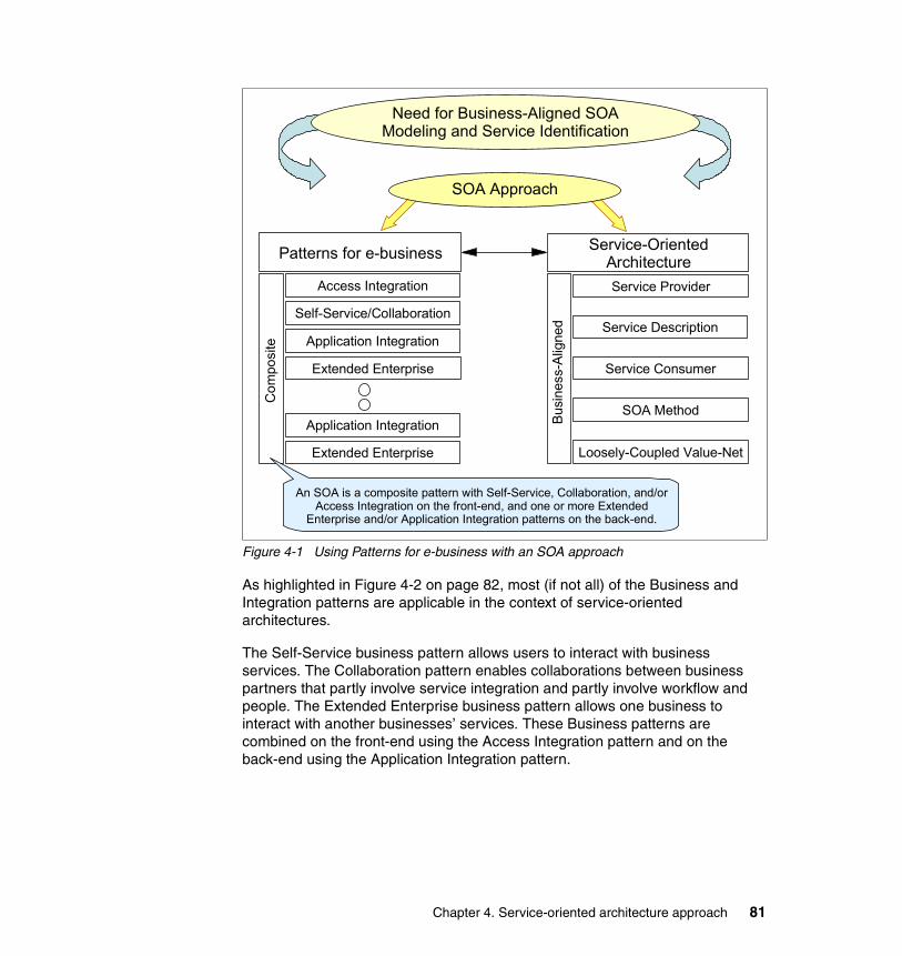
Figure 4-1 Using Patterns for e-business with an SOA approach
As highlighted in Figure 4-2 on page 82, most (if not all) of the Business and Integration patterns are applicable in the context of service-oriented architectures.
The Self-Service business pattern allows users to interact with business services. The Collaboration pattern enables collaborations between business partners that partly involve service integration and partly involve workflow and people. The Extended Enterprise business pattern allows one business to interact with another businesses’ services. These Business patterns are combined on the front-end using the Access Integration pattern and on the back-end using the Application Integration pattern.
SOA Approach
Need for Business-Aligned SOA Modeling and Service Identification
Service-Oriented Architecture
Busi
ness
-Alig
ned
Loosely-Coupled Value-Net
Service Description
Service Consumer
SOA Method
Service Provider
Patterns for e-businessC
ompo
site
Extended Enterprise
Application Integration
Extended Enterprise
Application Integration
Self-Service/Collaboration
An SOA is a composite pattern with Self-Service, Collaboration, and/or Access Integration on the front-end, and one or more Extended
Enterprise and/or Application Integration patterns on the back-end.
Access Integration
Chapter 4. Service-oriented architecture approach 81

Figure 4-2 SOA with Access Integration, Self-Service, Collaboration, Extended Enterprise, and Application Integration
We focus on Self-Service, Extended Enterprise and Application Integration in this publication, exploring how the Business patterns, Integration patterns, Application patterns, Runtime patterns and Product mappings can be applied at the appropriate stages of the SOA approach.
4.2 Business scenario: Supply chain managementThe Web Services Interoperability Organization (WS-I) has developed a supply chain management business scenario to demonstrate features of the WS-I Basic Profile 1.0. The WS-I sample business scenario and the technical solution overview are described in the following documents:
� WS-I Supply Chain Management Use Cases 1.0
� WS-I Usage Scenarios 1.0
� WS-I Supply Chain Management Technical Architecture 1.0
For full details, see the Web Services Interoperability Organization Web site:
http://www.ws-i.org
We use this business scenario to show how the Patterns for e-business and SOA approach can be used to develop solutions to real-world business requirements, that are based on interoperatibility principles defined in the WS-I Basic Profile.
Acce
ss In
tegr
atio
n Self-Service
Information Aggregation
Extended Enterprise Appl
icat
ion
Inte
grat
ionSelf-ServiceSelf-Service
Collaboration
82 Patterns: Service Oriented Architecture and Web Services

As shown in Figure 4-3, this business scenario is a simplified supply chain for a consumer electronics retailer. In a typical B2C model, customers may access the retailer’s Web site, review the catalog, and place orders for products such as TVs, DVD players and video cameras.
The retailer system requests fulfilment of a consumer’s order from the internal company warehouse, which responds as to whether line items from the order can be filled. If stock for any line item falls below a minimum threshold in the warehouse, a replenishment order is sent to an external manufacturer using the B2B model.
The manufacturer does not immediately fulfil replenishment orders. It will complete the order at some later time (possibly after completing a manufacturing run).
Figure 4-3 High-level business context
Now, rather than taking the WS-I Supply Chain Management Technical Architecture as a given, we will apply the SOA approach that includes the Patterns for e-business to this business scenario.
4.3 Steps of the SOA approachThis section introduces a method for discovering services (top-down) and leveraging services (bottom-up, from legacy and packaged applications). It includes a combination of techniques and steps that describe how to employ
Browser
ConsumerRetailer
Inte
rnet
Inte
rnet
Organization boundary
Warehouse
Logging Facility
Manufacturer
Chapter 4. Service-oriented architecture approach 83
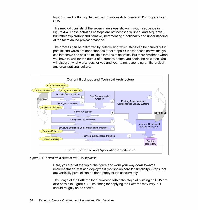
top-down and bottom-up techniques to successfully create and/or migrate to an SOA.
This method consists of the seven main steps shown in rough sequence in Figure 4-4. These activities or steps are not necessarily linear and sequential, but rather exploratory and iterative, incrementing functionality and understanding of the team as the project proceeds.
The process can be optimized by determining which steps can be carried out in parallel and which are dependent on other steps. Our experience shows that you can interleave and spin off multiple threads of activities. But there are times when you have to wait for the output of a process before you begin the next step. You will discover what works best for you and your team, depending on the project and organizational culture.
Figure 4-4 Seven main steps of the SOA approach
Here, you start at the top of the figure and work your way down towards implementation, test and deployment (not shown here for simplicity). Steps that are vertically parallel can be done pretty much concurrently.
The usage of the Patterns for e-business within the steps of building an SOA are also shown in Figure 4-4. The timing for applying the Patterns may vary, but should roughly be as shown.
Technology Realization Mapping
Current Business and Technical Architecture
Future Enterprise and Application Architecture
Domain Decomposition
Subsystem Analysis
Service Allocation
Goal Service Model Creation
Existing Assets Analysis Componentize Legacy Systems
Structure Enterprise Components using Patterns
Service Repository
Leverage Component Service Repository
1a
3 21b
4
6
7
Component Specification 5
Bottom-up
Top-down
Composite Patterns
Business Patterns Integration Patterns
Application Patterns
Runtime Patterns
Product Mapping
84 Patterns: Service Oriented Architecture and Web Services
We start the process when the business problem suggests the use of a service-oriented approach. Business problems involving exposure of back-end business services at the edge of the enterprise are typical candidates.
The top-down aspect of the SOA approach comes from taking business perspectives and models into consideration: Business functions, processes, sub-processes, and use cases are elaborated to form the outlines of component boundaries.
Components provide boundaries and containers for services (often discovered through use case analysis and goal-service model creation). Services are the units of functionality that are exposed for business process orchestration and choreography and the creation of composite applications. Components provide these services on their interfaces and will often contain finer grained object hierarchies and/or legacy systems that implement them.
In the following sections, we outline the seven key steps necessary to support component-services architectures. We apply each of the steps to the WS-I supply chain management sample scenario. The supply chain scenario is reasonably simple, so our application of the SOA approach will be at a comparable level of detail.
As already stated, the SOA approach does support legacy integration (starting at Step 1b Existing Assets Analysis in Figure 4-4 on page 84), but we do not cover this aspect in this publication.
4.3.1 Domain decompositionIn this step we decompose the domain into its constituent business architecture consisting of value-chain, business processes, sub-processes, and use cases.
From a business perspective, the domain consists of a set of functional areas. We decompose the domain into functional areas across the value-net; these are often good candidates for implementation as technology subsystems. Figure 4-5 on page 86 shows our domain decomposition for the supply chain management scenario.
Chapter 4. Service-oriented architecture approach 85

Figure 4-5 Domain decomposition of value chain into functional areas and domains
In defining the functional areas across a value-chain or value-net we define the scope of the effort:
� Is it within the enterprise; is it across one, two or more business lines?
� Is it across a value-chain within business partners in a supply chain?
After decomposing domain into a value-chain of functional areas, we then decompose each functional area into processes, sub-processes, and business use cases.
Use case modelThe decomposition of the functional areas described above leads to the following set of business use-cases:
� UC1: Purchase Goods� UC2: Source Goods� UC3: Replenish Stock� UC4: Supply Finished Goods� UC5: Manufacture Finished Goods� UC6: Configure and Run Demo (Not implemented in our sample.)� UC7: Log Events� UC8: View Events
For a full description of the use cases, please see WS-I document Supply Chain Management Use Case Model, available at:
http://www.ws-i.org/
The use case model is shown in Figure 4-6 on page 87.
<<Customer>> <<Retailer>> <<Warehouse>> <<Manufacturer>>
<<Logging Facility>>
3 Manufacturers
Value Chain Participant
Legend
86 Patterns: Service Oriented Architecture and Web Services

Figure 4-6 WS-I SCM use case model
We can now use the business use cases (high-level, coarse-grained use cases like Purchase Goods) to further decompose the domain, as shown in Figure 4-7 on page 88. The business use cases identified are good candidates for services that will ultimately be exposed as Web services on an enterprise component. The business use case definitions are business driven and aligned, and offer a common, reusable “chunk” of business functionality.
ConsumerRetailer System
Manufacturing System
Demo System
Demo User
UC1: Purchase Goods
UC2: Source Goods
UC3: Replenish Stock
UC4: Supply Finished Goods
UC5: Manufact ure Finished Goods
UC6: Configure and Run Demo
UC7: Log Events
UC8: View Events
«include» «include»
Chapter 4. Service-oriented architecture approach 87

Figure 4-7 Domain decomposition into business processes and business use cases
With the business use cases, it is important to define the data to be input and output from each service or external invocation at least at a high level. These definitions are then refined during component and service specification.
As we move into design, each functional area is mapped to one or more subsystems in the architecture. Functional areas are a business notion, while the subsystems are a technology notion. There is a straightforward mapping between them, so we often find that at least one subsystem will then be identified and elaborated for each functional area. Similarly, business level use cases can be mapped to system level use cases in this stage.
In this way, each functional area or business process can be thought of as an IT subsystem that creates a natural business-driven boundary for the large-grained enterprise components that provide services.
In contrast, object-oriented analysis and design tends to produce object graphs of relatively tightly coupled finer-grained objects, which tends to impede component reuse. With the SOA approach this is avoided by identifying the larger encompassing (perhaps virtual) structure first. The constituent elements are then
<<Customer>>
Purchase Goods
Use-Case
Value-ChainParticipant
<<Warehouse>>
ReplenishStock
SourceGoods
<<Logging Facility>>Log
Events View Events
<<Retailer>>
SourceGoods
<<Manufacturer>>
SupplyGoods
ManufactureGoods
Log Events
3 Manufacturers
Purchase Goods
ReplenishStock
Supply Goods
Log Events
88 Patterns: Service Oriented Architecture and Web Services

refined through a more top-down approach, or allocated (if leveraging legacy, for example).
Applying Business and Application Integration patternsAt each stage of the SOA approach, we can leverage corresponding assets from the Patterns for e-business. We start with Business patterns to define high-level business participants and their relationships, using the functional areas and business use cases identified in domain decomposition.
Let us look at how we applied Business and Integration patterns to the WS-I SCM sample business problem. We know there are two business models associated with it:
� A B2C interaction between the consumer (end user) and the retailer’s business system; and
� A B2B interaction between the retailer’s warehouse and the external manufacturers
This implies the use of the Self-Service and Extended Enterprise business patterns. We can also use the Application Integration pattern to integrate the internal service consumers and service providers in the value-chain, and the Extended Enterprise business pattern to service consumers and service providers across enterprise boundaries. We applied these Patterns to the SCM business scenario, as shown in Figure 4-8.
Figure 4-8 Supply chain management Business and Application Integration patterns
Self-Service Extended Enterprise
Browser
ConsumerRetailer
Inte
rnet
Inte
rnet
Organization boundary
Warehouse
Logging Facility
Manufacturer
Legend
Business Pattern
Application IntegrationPattern
Appl
icat
ion
Inte
grat
ionA
pplic
atio
n In
tegr
atio
n
Application Integration
Chapter 4. Service-oriented architecture approach 89
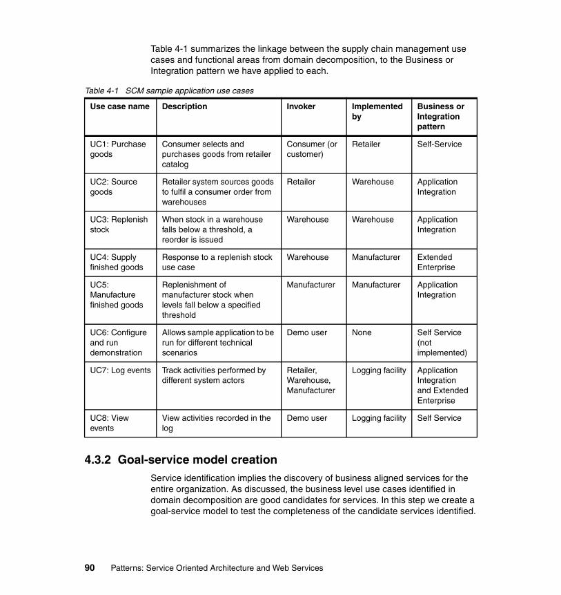
Table 4-1 summarizes the linkage between the supply chain management use cases and functional areas from domain decomposition, to the Business or Integration pattern we have applied to each.
Table 4-1 SCM sample application use cases
4.3.2 Goal-service model creationService identification implies the discovery of business aligned services for the entire organization. As discussed, the business level use cases identified in domain decomposition are good candidates for services. In this step we create a goal-service model to test the completeness of the candidate services identified.
Use case name Description Invoker Implemented by
Business or Integration pattern
UC1: Purchase goods
Consumer selects and purchases goods from retailer catalog
Consumer (or customer)
Retailer Self-Service
UC2: Source goods
Retailer system sources goods to fulfil a consumer order from warehouses
Retailer Warehouse Application Integration
UC3: Replenish stock
When stock in a warehouse falls below a threshold, a reorder is issued
Warehouse Warehouse Application Integration
UC4: Supply finished goods
Response to a replenish stock use case
Warehouse Manufacturer Extended Enterprise
UC5: Manufacture finished goods
Replenishment of manufacturer stock when levels fall below a specified threshold
Manufacturer Manufacturer Application Integration
UC6: Configure and run demonstration
Allows sample application to be run for different technical scenarios
Demo user None Self Service (not implemented)
UC7: Log events Track activities performed by different system actors
Retailer, Warehouse, Manufacturer
Logging facility Application Integration and Extended Enterprise
UC8: View events
View activities recorded in the log
Demo user Logging facility Self Service
90 Patterns: Service Oriented Architecture and Web Services

By interviewing business owners, querying them on the goals within the scope of work, we can create a tree of related sub-goals that are prerequisites to achieving the initial high-level, often intangible, and lofty goal. Each level of sub-goal is broken down to a set of further sub-goals until the services required to fulfill them are clear. This is called a goal-service model.
To create a goal-service model, identify the goals and sub-goals that must be realized in order support higher level goals. Then associate the sub-goals with the services required to realize the sub-goals. This will make services traceable back to the goals that the business indicates it needs to achieve. This traceability of services back to business goals is essential to ensure that the complete set of business services is anticipated as early as possible.
Various notations are possible for a goal-service model. We provide a simple example using a nested list of goals, sub-goals, and services in Figure 4-9. This example covers the retailer functional area.
Figure 4-9 Goal-service model example
Goal-service model for retailer business function:
1. Increase revenue
2. Increase sales
3. Provide self-service shopping capability
3.1. Purchase Goods
3.2. Source Goods
3.3. Provide user-friendly interaction experience
3.3.1. Get Catalog
3.3.2. Manage Shopping Cart
4. Maintain accounting records
4.1. Log Events
4.2. View Events
Key:
� Goals are shown in regular text.
� Services are shown in italic.
� Value-adds (additional services needed that were not discovered during Domain Decomposition) are shown in bold.
Chapter 4. Service-oriented architecture approach 91

Starting with the high-level business goal of increasing revenue, we identify lower-level subgoals and services needed to realize the business goals above. For the SCM sample, the top level goal of increasing revenue may be achieved by increasing sales. To increase sales we can provide more accessible and convenient self-service shopping capability. The Purchase Goods and Source Goods use cases identified in domain decomposition provide this capability.
Looking closer at the self-service shopping goal, it is important that interaction experience provided is user-friendly. To achieve this we need to provide the user with a shopping catalog that she can browse. In a real world scenario some sort of shopping cart facility would also be usual. This simple goal-service model helped us to identify that some additional services are needed to support the business goals. We will need to revisit the domain decomposition to incorporate the new services.
All the services identified are seen to directly support the business domain’s needs and goals. This traceability is a very significant factor in ensuring that the gap between business required services and IT system implementations remains minimal.
4.3.3 Subsystem analysisAfter completing domain decomposition we have an idea of the functional areas in the business domain and how they interact within the value-chain for the business domain. We have a fractal (recursive or composite) view of the business domain: An extended enterprise with suppliers and customers, with individual business lines within an organization, and business processes and use cases within the business lines.
Now we move more into design- and architecture-driven decisions. Subsystem analysis refines the business use cases into system use cases that support a given business process. Subsystems are composed of business components (such as Customer, Order, and Product) and technical components (such as messaging, security, and logging).
During subsystem analysis, business and technical components are identified as follows:
� Analyze the process flow within the subsystem (often a sequence of use cases) to discover/identify candidate business components.
� Use non-functional requirements to find technical components.
� Identify the required functionality for each business component; tat is, the system level use cases each component must it support.
92 Patterns: Service Oriented Architecture and Web Services

The high-level business use cases discovered during domain decomposition are often good candidates to be placed on the interface of these subsystem components and expose the enterprise component's services. These business use cases often collaborate to support a business process.
In our SCM scenario, the four main subsystems identified are Retailer, Warehouse, Manufacturer, and Logging Facility. Each of these subsystems exposes a set of business services. For convenience, we can lump a set of finer grained services as a single callable service with several operations for the individual functions required.
Figure 4-10 shows the Retailer subsystem. After goal-service model creation, we split the Purchase Goods business use case into Get Catalog and Submit Order services.
Figure 4-10 Business use cases are exposed on the subsystem
Each business use case relies on a set of system use cases encapsulated in the subsystem. The subsystem leverages the business and technical components to realize the use case and support the exposed business service such as Submit Order.
The model shown in Figure 4-10 is only meant to provide a simple example of how subsystem analysis is performed. In practice, standard UML modeling techniques are used, with business use cases realized by subsystems, and system use cases realized by business and technical objects.
Retailer Enterprise Component
Replenish StockSource Goods
Retailer
Catalog
Product
TechnicalComponents
RetailerSoapBindingImpl
Customer
Order
BusinessComponents
Submit Order
Get Catalog
Chapter 4. Service-oriented architecture approach 93

After completing subsystem analysis, we end up with the following larger-grained components that are being implemented as services:
� Retailer Service provides the functionality to access the product catalog and to place orders.
� Warehouse Service supports the shipment of products ordered and updates stock inventory as products ship. Where inventory falls below a threshold, it will submit a Purchase Order (PO) to a Manufacturer for finished goods.
� Warehouse Callback Service receives notification from a manufacturer that a PO has been processed, successful or not.
� Manufacturer Service accepts PO submission for finished goods and initiates the manufacturing process.
� Logging Service logs events as they happen and supports retrieval of events logged for display to the end-user.
At this point these coarse-grained services can be composed into an orchestration. Flow modeling tools such as IBM WebSphere Business Integration Modeler are an important aid in this area.
Applying Application patternsApplication patterns help structure the business and technical services needed for the SCM scenario at a high-level, as shown in Figure 4-11 on page 95.
94 Patterns: Service Oriented Architecture and Web Services

Figure 4-11 Supply chain management Application patterns
In this simplified solution, we show the five primary services needed to support the business:
� Retailer service
� Warehouse service
� Warehouse callback service
� Logging facility service
� Manufacturer service
Notice the use of the Direct Connection application pattern between services within the Enterprise. The Direct Connection application pattern is the simplest interaction type based on a 1-to-1 topology. It allows a service consumer and provider within the organization to directly communicate with each other. For example, when a customer submits an order, the Retailer Service will then send a message to a Warehouse service to locate the ordered goods and request shipment.
The Exposed Router application pattern is applied to the business need of a Warehouse having to submit a Purchase Order to a specific Manufacturer for finished goods when the inventory falls below the pre-defined threshold limit. The retailer’s warehouse can interact with any of the three Manufacturers in the
Extended Enterprise::Self-Service::Stand Alone Single Channel
Browser
Consumer
Inte
rnet
Organization boundary
Warehouse Service
Logging Facility
Manufacturer ServiceWarehouse
Callback Service
Inte
rnet
ExposedRouter
Exposed Direct Connection
LegendBusiness Pattern::Application Pattern
Application IntegrationPattern
ExposedRouter
Appl
icat
ion
Inte
grat
ion:
:D
irect
Con
nect
ion
Appl
icat
ion
Inte
grat
ion:
:D
irect
Con
nect
ion
Appl
icat
ion
Inte
grat
ion:
:D
irect
Con
nect
ion
Application Integration::Direct Connection
Retailer Service
Present-ation
Chapter 4. Service-oriented architecture approach 95

sample application. The Router pattern applies to solutions where the source application initiates an interaction that is forwarded to, at most, one of multiple target applications. The selection of the target application is controlled by the Router tier.
When a Manufacturer has completed processing a purchase order submitted by a Warehouse, it notifies the Warehouse asynchronously via the Warehouse Callback Service of its completion. The Exposed Router pattern is used to control the services that can be invoked from outside the organization by external partners, such as the Manufacturers.
4.3.4 Service allocationWe have identified all the required services through a combination of domain decomposition and goal-service modeling. In this step, service allocation, we ensure that all the services identified have a “home” and that they are all traceable back to business goals and to components.
In this way we not only ensure that every service has business value, but also that all the services have been identified. Importantly, we are also managing the proliferation of services; like objects in the object-oriented paradigm, services tend to proliferate if not carefully managed.
Service allocation asks who (which component) will provide the implementation and management of each service. The answer will depend on whether you are a service provider or consumer.
Service consumers want the flexibility to replace an implementation based on new functional requirements, non-functional characteristics (such as higher volume handled, less down time), and economic factors (such as cheaper service).
Service providers, on the other hand, will want to implement the interface using one or more of their components or existing functionality (if not componentized).
Figure 4-12 on page 97 shows the traceability between the services identified in the goal-service model, and the new and existing components that implement and manage each service.
96 Patterns: Service Oriented Architecture and Web Services

Figure 4-12 Service allocation
Service allocation is trivial in our supply chain management sample because we we have only a small number of services, and we assume that there are no existing internal service providers that need to be considered. We do, however, need to allocate the responsibility to implement the Manufacturer service providers to our external manufacturer business partners.
The WS-I Supply Chain Management Sample Application Architecture document defines the following set of interfaces for the supply chain management sample:
http://www.ws-i.org/SampleApplications/SupplyChainManagement/2002-08/Retailer.wsdlhttp://www.ws-i.org/SampleApplications/SupplyChainManagement/2002-08/Warehouse.wsdlhttp://www.ws-i.org/SampleApplications/SupplyChainManagement/2002-10/Manufacturer.wsdlhttp://www.ws-i.org/SampleApplications/SupplyChainManagement/2002-08/LoggingFacility.wsdl
4.3.5 Component specificationAfter subsystem analysis, we have defined the subsystem interfaces, system use cases, business and technical components, their dependencies and flow. We have then ensured that each identified service is assigned to a component.
Component 1
Services
Goals
Previously Discovered Services
Services Discovered During Goal Service Modeling
Component 2
Chapter 4. Service-oriented architecture approach 97

The next step is to develop specifications for the each of the components needed. Properties, such as those shown in the template shown in Figure 4-13, need to be captured for each business or technical component that will participate in a release within the scope of the project.
Figure 4-13 Component specification template
4.3.6 Structure components and services using patternsWe have applied business and architectural analysis to identify and define the components providing the services. We have allocated services to components and developed specifications for each of the components.
We structure these components and services using patterns in this step.
Applying Runtime patternsIn this step, we can use Patterns for e-business Runtime patterns to establish the middleware structure needed to support the services identified, and then allocate each service to a logical middleware node. We applied the Runtime patterns shown in Figure 4-14 on page 99 to the SCM scenario.
Rules<rule 1><rule 2>
Services<service 2><service 1>
Attributes<data element 1><data element 2>
Uses Components<dependency on component 1>
Variation PointsPluggable Rules[Configurable] WorkflowConfigurability Requirements
Component Specification
<<Component>>
98 Patterns: Service Oriented Architecture and Web Services

Figure 4-14 Application of Runtime patterns during the structure components and services step
Here we have three distinct Runtime patterns for our SCM solution. Other variations of these Runtime patterns can be used to address availability and performance requirements, but are we focusing the simpler, entry-level Runtime patterns in this publication.
For the U2B interaction, we have variation 1 of the Stand-Alone Single Channel runtime pattern. This variation uses a Web server redirector containing the Web server and an application server, effectively splitting the function of a Web application server across two machines. The application server resides in the internal network to provide it with more security. The application server node will run both presentation and business logic. The Web server remains in the DMZ and serves static pages. A Web server redirector is used to forward the requests from the Web server to the application server.
For the interaction between services within the organization, the Direct Connection runtime pattern comprises of a source service accessing the target
Web Server Redirector
Dom
ain
Fire
wal
l
Prot
ocol
Fire
wal
l
Inte
rnet
Dom
ain
Fire
wal
l
Enterprise Domain Partners
DMZ DMZInter-Enterprise
ZoneInternal NetworkOutside World
Stand-Alone Single Channel Application Pattern::Runtime Pattern: Variation 1
Direct Connection Application Integration
Pattern::Runtime Pattern
Retailer Service on this node
Manufacturer Service on Partner Infrastructure
Exposed Router Application
Pattern::Runtime Pattern
Connector
Prot
ocol
Fire
wal
l
Exposed Direct Connection Application
Integration Pattern::Runtime Pattern
Exposed Router
Rules Repository
Application Server / Services
Directory and Security Services
ConnectorApplication
Server / Services
Database
Application Server / Services
Rules RepositoryConnector
Partner Infrastructure
InterEnterprise Network
Infrastructure
Warehouse & Warehouse Callback Services on this node
Logging Service on this node
Service bus
Chapter 4. Service-oriented architecture approach 99

service via a connector. Connectors provide the connectivity between two components. In this instance, we use the Direct Connection runtime pattern to implement a logical service bus, as described in “Direct Connection using a service bus” on page 65. The Exposed Direct Connection runtime pattern allows external access to the Logging service.
For the B2B interactions, the Router variation of the Exposed Broker runtime pattern is used. The Router can perform intelligent routing of messages to one target service at a time. It does not include the simultaneous distribution or decomposition capabilities that the Broker node provides. (Ideally, the Router variation of the Exposed Broker runtime pattern would also be used for external access to the Logging service. We have used the Exposed Direct Connection runtime pattern simply to demonstrate the use of this pattern.)
In Chapter 6 through Chapter 9 we examine in detail the implementation of this solution across four stages. Each stage builds on the previous stage, allowing us to work our way gradually to a comprehensive solution.
As stated earlier, valid alternate Runtime patterns are possible, include the following:
� Router instead of Direct Connection pattern for the interactions between:
– Retailer Service and Logging Service– Warehouse Service and Logging Service– Warehouse Callback Service and Logging Service
if there is a need for protocol conversion between the services.
� Serial Process instead of Direct Connection pattern for the Retailer-to-Warehouse service interaction if the process logic is separated from the application logic.
� Exposed Router instead of Exposed Direct Connection pattern for the Manufacturer-to-Logging service interaction. Use of the gateway to decouple the deployment and invocation of the service is a more prudent choice, especially in an inter-enterprise environment.
4.3.7 Technology realization mappingOnce the functionality of the services and components have been specified in detail, their implementation mechanism must be resolved. The choice of how to realize the implementation of the specification is a key architectural step.
You can build everything from scratch. Or you can out source it completely as a turn-key solution. Between these two extremes lies the most common needs of IT organizations: To decide what to build, what to buy. However, it is important to realize that these are not the only alternatives. As shown in Figure 4-15 on
100 Patterns: Service Oriented Architecture and Web Services

page 101, there are various alternatives to the traditional “build versus buy” decision, namely:
� Build new component functionality (roll your own).
� Transform legacy to enable reuse of functionality exposed as services.
� Integrate by wrapping legacy systems.
� Buy and integrate with third party products.
� Subscribe and out source parts of the functionality, especially via Web services.
Figure 4-15 Plan and design your service implementation carefully
A service’s implementation can be realized by wrapping a legacy system with a message queue service or a Web service. But in most cases mere exposure of legacy functionality is not sufficient. Componentization of the legacy system or a small subset of the system must take place to properly expose the functionality required. This process is called transformation, where the legacy system is transformed from one state to a componentized state. A key factor is the scope of componentization: Avoiding the “boil the ocean” syndrome where all the legacy is broken into parts. Rather, an appropriate subset is selected and transformed through componentization. This is mostly an automated process. The IBM Legacy Transformation Offering focuses on these kinds of solutions.
Subscription assumes that an enterprise application Integration model has been implemented and there are services to subscribe to, in a hub and spokes architecture.
Once we have specified the components that we need, we can weigh the advantages and disadvantages of how to realize the components. This mapping is called a technology realization.
A table like Table 4-2 on page 102 can be created for this purpose.
Build Transform Integrate Subscribe Buy Outsource
Chapter 4. Service-oriented architecture approach 101

Table 4-2 Technology realization mapping table
In our simple SCM example we move straight from the Runtime patterns identified in “Structure components and services using patterns” on page 98 to applying the Product mappings.
Applying Product mappingsThe Patterns for e-business Product mappings can be used with component realization to help you identify and select proven and tested middleware implementations for your scenario. We applied the Product mappings shown in Figure 4-16 on page 103 to the SCM scenario.
Business process
Sub-process Use case /service
Component Current Implementation(if exists)
Future Technology Realization mechanism
102 Patterns: Service Oriented Architecture and Web Services

Figure 4-16 Application of Product mappings during the component specification step
We use IBM WebSphere Application Server V5.1 to host all the services in the our SCM solution. WebSphere hosts the front-end, user interface application and each of the services implemented:
� Retailer service
� Warehouse service
� Warehouse callback service
� Logging facility service
� Manufacturer service
In Chapter 6, “HTTP service bus” on page 159, we look in detail at how the service consumers and providers in the scenario can be integrated using the SOAP/HTTP Web services support provided with IBM WebSphere Application Server V5.1 and the Direct Connection runtime pattern.
Web Server Redirector
Dom
ain
Fire
wal
l
Prot
ocol
Fire
wal
l
Inte
rnet
Dom
ain
Fire
wal
l
Enterprise Domain Partners
DMZ DMZInter-Enterprise
ZoneInternal NetworkOutside World
Stand-Alone Single Channel Application Pattern::Runtime Pattern: Variation 1
Direct Connection Application Integration
Pattern::Runtime Pattern
Retailer Service on this node
Manufacturer Service on Partner Infrastructure
Exposed Router Application
Pattern::Runtime Pattern
Connector
Prot
ocol
Fire
wal
l
Exposed Direct Connection Application
Integration Pattern::Runtime Pattern
Exposed Router
Rules Repository
Application Server / Services
Directory and Security Services
ConnectorApplication
Server / Services
Database
Application Server / Services
Rules RepositoryConnector
Partner Infrastructure
InterEnterprise Network
Infrastructure
Warehouse & Warehouse Callback Services on this node
Logging Service on this node
Service bus
Windows 2000 + SP4IBM WebSphere Application Server V5.1 HTTP Plug-inIBM HTTP Server 1.3.26
Windows 2000 + SP4IBM SecureWay Directory V3.2.1IBM HTTP Server 1.3.19.1IBM GSKit 5.0.3IBM DB2 UDB EE V7.2 + FP5
Internet
Windows 2000 + SP4IBM DB2 UDB ESE V8.1
Red Hat Linux AS 2.1IBM WebSphere Application Server V5.1
Windows 2000 + SP4IBM WebSphere Application Server V5.1
AIX 5.1 ML4IBM WebSphere Application Server V5.0.2.4 Network Deployment - WS GateWay
Windows 2000 + SP4IBM WebSphere Application Server V5.1
AIX 5.1 ML4IBM WebSphere Application Server V5.0.2.4 Network Deployment - UDDI RegistryIBM DB2 UDB ESE V8.1
Chapter 4. Service-oriented architecture approach 103

In Chapter 7, “JMS service bus” on page 229, we look at adding reliable messaging using SOAP/JMS Web services. We examine how IBM WebSphere Application Server V5.1 service consumers and providers can be reconfigured to communicate using the IBM WebSphere MQ JMS provider, instead of HTTP.
In Chapter 8, “Service directory” on page 251, we add the UDDI Registry provided with IBM WebSphere Application Server Network Deployment V5.1.
In Chapter 9, “Web service gateway” on page 279, we include the Web Services Gateway provided with IBM WebSphere Application Server Network Deployment V5.1 to allow integration between the Warehouse and Manufacturer services using the Broker runtime pattern.
4.4 Summary and conclusionThe method described here helps map a current business model and its underlying IT architecture to a service-oriented enterprise and application architecture. The combination of SOA and Patterns for e-business produces a powerful set of best-practices and design decisions that help expedite mapping of business processes to IT and the creation of a robust service-oriented architecture that is in line with the needs of the business.
The SOA approach discussed here is an extension that can be easily added to your current method. It combines a top-down and bottom-up approach to the modeling, design and implementation of a service-oriented architecture for on-demand computing.
4.5 Where to find more informationFor more information on topics discussed in this chapter, see:
� The following Web Services Interoperability Organization documents:
– WS-I Basic Profile 1.0
– WS-I Supply Chain Management Use Cases 1.0
– WS-I Usage Scenarios 1.0
Note: When integrating between J2EE application servers, RMI/IIOP is generally the preferred approach. The intention of the SCM product mapping is to demonstrate that WebSphere V5.1 can be used to implement all of the components of the service-oriented solution, and to demonstrate WebSphere conformance with all of the WS-I Basic Profile 1.0 features covered by the SCM sample.
104 Patterns: Service Oriented Architecture and Web Services

– WS-I Supply Chain Management Technical Architecture 1.0
WS-I documents are available at:
http://www.ws-i.org
� Ali Arsanjani, A Domain-language Approach to Designing Dynamic Enterprise Component based Architectures to Support Business Services, Proceedings of Technology of Object-oriented Languages and Systems 39, 2001
� Keith Levi, Ali Arsanjani, A goal-driven approach to enterprise component identification and specification, Communications of the ACM Volume 45 Issue 10, 2002
Chapter 4. Service-oriented architecture approach 105

106 Patterns: Service Oriented Architecture and Web Services

Chapter 5. Technology options
This chapter describes some of the Web services related technology options available to you when developing a service-oriented architecture. You can use the information in this chapter, along with pointers to other sources, as input to your architectural decision making when considering Runtime patterns and Product mappings for the application patterns you choose to deploy.
In “A closer look at service-oriented architecture” on page 24 we presented an architectural stack and the elements that might be observed in a service-oriented architecture. We use this stack to structure our discussion of Web service technology options, as shown in Figure 5-1 on page 108.
5
© Copyright IBM Corp. 2004. All rights reserved. 107

Figure 5-1 Web services and the service-oriented architecture stack
The industry is working quickly to develop the additional standards that are required to simplify the implementation of service-oriented architectures. Brief descriptions are provided in this chapter for both current and emerging standards for each level of the architecture stack. For more information, see the IBM developerWorks section on Web services standards:
http://www.ibm.com/developerworks/views/webservices/standards.jsp
Service
Serv
ice
Reg
istry
Polic
y
Secu
rity
Tran
sact
ion
Man
agem
ent
Functions Quality of Service
WS-
Polic
y
WS-
Tran
sact
ion
WS-
Secu
rity
WS-
Coo
rdin
atio
n
WS-
Trus
t
WS-
Man
agea
bilit
y
Business Process
BPEL4WS
Service Description
WSDL XML
Service Communication Protocol
SOAP
TransportWS-ReliableMessaging
HTTP JMS SMTP
WS-
Insp
ectio
nU
DD
I
BEEP
Current Standards
Emerging Standards
108 Patterns: Service-Oriented Architecture and Web Services

5.1 IntroductionThis chapter describes Web services technologies relevant to service-oriented architecture, including some of their advantages and disadvantages. For an overall perspective, some of the pluses and minuses of Web services are included in this section. It is not recommended that Web services are seen as the solution to all your integration problems, and should not be considered as the best architectural approach for all future solutions. Just as with any other technology or architectural approach, there are inherent advantages of using Web services in the right place and for the right reasons.
5.1.1 Advantages of Web servicesWhen appropriately selected and implemented, the use of Web services technologies can enable a business to:
� Deliver new IT solutions faster and at lower cost by focusing their code development on core business, and using Web services applications for non-core business programming.
� Protect their investment in IT legacy systems by using Web services to wrap legacy software systems for integration with modern IT systems.
� Integrate their business processes with customers and partners at less cost. Web services make this integration feasible by allowing businesses to share processes without sharing technology. With lower costs, even small businesses will be able to participate in B2B integration.
� Enter new markets and widen their customer base. Web services listed in UDDI registries can be “discovered” and thus are “visible” to the entire Web community.
5.1.2 Disadvantages of Web servicesAll new technologies have problems and disadvantages that should be taken into consideration before they are used. To try and assist you with identifying if Web services is appropriate or not, the following list gives some issues you should consider when selecting to use Web services:
� Binding to Web services dynamically requires that the contents of the UDDI registry be trusted. Currently, only private UDDI networks can provide such control over the contents.
� The SOAP server footprint is significant and the technology is relatively new, so adding the Web service provider stack to existing enterprise systems can be a problem.
Chapter 5. Technology options 109

� Standards for integration of business processes, management of transactions, and the awareness of the policies of interchanging partners are all still under development. To realize the promise of Web services, these types of standards should be available in implementation products.
5.2 TransportThe transport layer in our architectural stack, as shown in Figure 5-2, is related to the mechanisms used to move service requests from the service consumer to the service provider, and service responses from the service provider to the service consumer. There are a number of standards in use today for Web services, but the most common one is HTTP.
Figure 5-2 The transport layer
5.2.1 HTTPThe HTTP protocol is commonly used for the transport of service requests and responses. HTTP extensions and HTTP/1.1 are stable specifications used as the standard transport protocol of the World Wide Web.
The World Wide Web Consortium (W3C) has closed the HTTP Activity, as they have achieved the goal of creating a successful standard. The W3C has started
Transport
Business Process
Service Communication Protocol
Service Description
Service
Serv
ice
Reg
istry
Polic
y
Secu
rity
Tran
sact
ion
Man
agem
ent
Functions Quality of Service
110 Patterns: Service-Oriented Architecture and Web Services

a new activity to extend the XML protocol. The XML Protocol Working Group will define new HTTP bindings for XML, as a higher-level protocol.
Advantages of HTTPThere are a number of advantages of using HTTP as a transport for Web services interactions, including:
� HTTP is a widely adopted protocol. Any organization with a Web server has implemented HTTP, and any client using a Web browser uses HTTP. Therefore the HTTP infrastructure is widely available.
� The HTTP protocol is open and deployed on many different system types, including non-traditional computing devices such as PDAs.
� Most enterprises allow HTTP to travel freely through protocol firewalls. Therefore, there are fewer barriers to extended enterprise use of HTTP as a transport for Web services.
Disadvantages of HTTPHTTP is a light-weight and stateless protocol that was not originally designed to carry application data. Some of the disadvantages of using it for Web services include:
� The protocol is stateless. If any state data is required to maintain an application session, the applications must create and manage the state data.
� HTTP is not a reliable protocol. If reliable delivery of application data is required, the application must either:
– Develop a reliability framework, such as exchanging receipt messages.
– Use a more reliable protocol.
5.2.2 Java Message ServiceMessaging middleware is a popular choice for accessing existing enterprise systems in an asynchronous manner. Messaging communication is loosely coupled, as compared to tightly coupled technologies such as Remote Method Invocation (RMI) or Remote Procedure Calls (RPC). The sender does not need to know anything about the receiver for communication. The message to be delivered is sent to a destination (queue) by a sender component, and the recipient picks it up from there. Moreover, the sender and receiver do not both have to be available at the same time to communicate. Messaging is one of the options if you are implementing a solution based on the Message variation of the Direct Connection pattern in an intra-enterprise scenario.
Chapter 5. Technology options 111

Messaging middleware may be an appropriate transport protocol when there is a requirement for Web services to communicate:
� Asynchronously, where the sender of a message does not wait for a reply to the message
� Reliably, where the sender is assured that the message will be delivered
A standard way for using messaging middleware from a Java application is using the Java Message Service (JMS) interface. JMS offers Java programmers a common way to create, send, receive and read enterprise messages. The JMS specification was developed by Sun Microsystems with the active involvement of IBM, other enterprise messaging vendors, transaction processing vendors, and RDBMS vendors.
JMS has two messaging styles, or in other words, two domains:
� One-to-one, or point-to-point model� Publish/subscribe model
IBM JMS implementationsIBM provides two implementations of JMS:
� A JMS provider included with WebSphere Application Server V5.0. This can be used for asynchronous communication between applications running on WebSphere V5.0 servers.
� IBM WebSphere MQ V5.3 includes built-in JMS Provider support with enhanced performance features for integrating JMS applications with other applications. IBM WebSphere MQ takes care of network interfaces, assures once and once only delivery of messages, deals with communications protocols, dynamically distributes workload across available resources, and handles recovery after system problems. IBM WebSphere MQ is available for most popular operating system platforms.
Advantages of JMSThere are a number of advantages of using JMS as a transport for Web services interactions, including:
� JMS provides a more reliable transport than alternatives, such as HTTP.
� Asynchronous requests can be readily deployed.
� It leverages existing, enterprise-proven messaging systems.
112 Patterns: Service-Oriented Architecture and Web Services

Disadvantages of JMSAlthough JMS is an open standard for Java-based systems, the actual transport system must be provided by a software product. Therefore, there are several considerations, including:
� The communicating Web services must have access to JMS providers that can communicate with each other. Generally, this implies the same product must be installed. For example, both systems must have IBM WebSphere MQ installed.
� JMS is a Java-based standard and is not as readily accessible to systems that are not based on Java.
5.2.3 Simple Mail Transfer ProtocolSimple Mail Transfer Protocol (SMTP) is one of the protocols that has made the Internet extremely popular, and is the basis of Internet e-mail. Its objective is to transfer electronic mail reliably and efficiently between people. It is then different from other messaging protocols like IBM WebSphere MQ or JMS which have been designed to handle information transfer between programs.
SMTP is independent of the particular transmission subsystem and requires only a reliable ordered data stream channel. An important feature of SMTP is its capability to relay mail across transport service environments. It has been published originally as RFC 821 by the Internet Engineering Task force (IETF) in 1982. Since then new RFCs like RFC 2821 have enhanced the original standard to take into account new technical capabilities.
As a widely used messaging standard, SMTP is a potential transport for SOAP messages. The writers of the W3C SOAP 1.1 Note state that “SOAP can potentially be used in combination with a variety of other protocols; however, the only bindings defined in this document describe how to use SOAP in combination with HTTP and HTTP Extension Framework”. The W3C SOAP 1.1 Note is available at:
http://www.w3.org/TR/soap/
Most implementations currently use HTTP to transport SOAP messages, but there is no reason why you cannot use other layers, such as SMTP.
Apache SOAP SMTP transportApache SOAP has been included as a WebSphere SOAP engine since WebSphere V4.0. It has now been superseded by Apache Axis and by Web Services for J2EE.
Chapter 5. Technology options 113

The Apache SOAP distribution includes classes which permit the servicing of SOAP requests using e-mail. It does this using a combination of SMTP and POP. A class called SMTP2HTTPBridge must be running in a separate JVM on the server. As the name suggests, this class operates as a bridge, mapping requests between HTTP and SMTP. Strictly speaking, this is not an independent SMTP transport; what it really does is convert e-mail SOAP messages to and from HTTP SOAP messages.
SMTP and Web Services for J2EEThe Java API for XML Messaging (JAXM) Optional Package enables applications to send and receive document-oriented XML messages using a pure Java API. JAXM implements SOAP 1.1 with Attachments messaging so that developers can focus on building, sending, receiving, and decomposing messages for their applications instead of programming low level XML communications routines. The specifications ensure that message delivery can be accomplished by supporting a number of communications infrastructures and key networking transports including, but not limited to, HTTP(S) and SMTP. However, we have not been able to find a reference to an implementation on SMTP.
JAXM adds support for plugging-in higher level messaging protocols like ebXML. JAXM is not a full-fledged messaging API like JMS.
J2EE also provides a mail API. The JavaMail 1.3.1 API defines a set of abstract classes that model an e-mail system. The API provides a platform independent and protocol independent framework to build Java technology-based mail and messaging applications. The JavaMail API is implemented as a Java platform optional package and is also available as part of J2EE. The reference implementation includes the core JavaMail packages and IMAP, POP3, and SMTP service providers.
Where to find more informationFor more information on SMTP, see:
� The SOAP Protocol:
http://www.w3.org/TR/SOAP/
� Apache SOAP:
http://xml.apache.org/SOAP/
� SMTP:
http://www.ietf.org
114 Patterns: Service-Oriented Architecture and Web Services
5.2.4 HTTPRReliable HTTP (HTTPR) was a proposed protocol for offering the reliable delivery of HTTP packets between a server and a client, but was withdrawn in favor of the OASIS evolving WS-ReliableMessaging standards. The HTTPR proposal offers reliability by adding extensions to HTTP, whereas WS-ReliableMessaging, as covered in further detail in the following section, delivers reliability at the SOAP envelope level.
5.2.5 Emerging standards for transportCommonly used transport protocols for Web services are currently dominated by HTTP, for reasons discussed in “Advantages of HTTP” on page 111. However, for enterprises to depend on Web services for business critical processing, more reliable transport protocols are required. Some emerging work in this area is discussed in this section.
WS-ReliableMessagingAs discussed in “Disadvantages of JMS” on page 113, current reliable message transport mechanisms require communicating parties to be using the same infrastructure, such as IBM WebSphere MQ. The WS-ReliableMessaging draft standard has been developed to provide a framework for interoperability between different reliable transport infrastructures.
The draft standard was released in March 2003 by IBM, BEA, Microsoft, and TIBCO. The protocol defined in the standard provides four delivery assurance descriptions that must be implemented by partners in the communication:
� AtMostOnce� AtLeastOnce� ExactlyOnce� InOrder
The WS-ReliableMessaging draft standard uses WS-Policy (see 5.8, “Policy” on page 144) and associated standards as a framework for determining the capabilities and requirements of partners in a reliable messaging exchange. The authors also strongly recommend that communication be secured using WS-Security and associated standards (see 5.9.4, “Emerging standards for security” on page 151).
Where to find more informationFor more information on WS-ReliableMessaging, see:
http://www.ibm.com/developerworks/webservices/library/ws-rm/http://www.ibm.com/developerworks/webservices/library/ws-rmimp/
Chapter 5. Technology options 115

BEEPBlocks Extensible Exchange Protocol (BEEP) is a generic application protocol framework for peer-to-peer asynchronous interactions over a TCP/IP connection. Unlike HTTP, BEEP does not have a notion of a server or client, and rather initiates a message-based communication session when a requestor initiates a request for connection with a provider.
Standardized by the Internet Engineering Task Force (IETF), BEEP supplies a protocol framework to manage peer-to-peer connection, authentication, message transport and error handling. But all this comes at a cost, and as such BEEP does not lend itself for communications that could be categorized as one-shot such as DNS look-up or tightly coupled RPC protocols like NFS. The appropriate environment for the use of BEEP is when you require an application protocol framework that is:
� Connection-oriented: Any BEEP based communication is expected to be initiated and disconnected for each interaction. In other words BEEP is expecting your application to connect, undertake the required task, and disconnect.
� Message-oriented: Just as with the fundamental concepts of SOAs, applications using BEEP to send data will do so based on well defined and structured data, giving the ability for the applications to be loosely coupled with limited knowledge of each others’ implementation.
� Asynchronous: BEEP, unlike HTTP, is a peer-to-peer style communication framework, which does not restrict the interactions to be in a particular order.
Where to find more informationFor more information on BEEP specifications, see:
http://www.beepcore.org
5.3 Service communication protocolThe service communication protocol layer of our architectural stack, as shown in Figure 5-3 on page 117, describes and defines the technologies and standards required to supply a transport mechanism between integrated services. If we consider the transport layer of the stack (discussed in the previous section) to be represented by a road between two end points, then the service communication protocol layer would be the vehicles traveling on the road, facilitating the transport of a package between the package sender and the receiver.
116 Patterns: Service-Oriented Architecture and Web Services

Figure 5-3 The service communication protocol layer
5.3.1 SOAPSimple Object Access Protocol (SOAP) is a network-, transport-, and programming language-neutral protocol that allows a service consumer to call a remote service provider. The message format is XML. The currently adopted standard is W3C’s SOAP 1.1 specification, while SOAP 1.2 is in the review process.
SOAP has the following characteristics:
� SOAP is designed to be simple and extensible.
� SOAP provides a framework to describe message content and process instructions, and an optional set of encoding rules for representing defined data-types.
� All SOAP messages are encoded using XML.
� SOAP is transport protocol independent. HTTP is one of the supported transports. Hence, SOAP can be run over an existing Internet infrastructure.
� There is no distributed garbage collection. Therefore, call by reference is not supported by SOAP; a SOAP client does not hold any stateful references to remote objects.
Transport
Business Process
Service Communication Protocol
Service Description
Service
Serv
ice
Reg
istry
Polic
y
Secu
rity
Tran
sact
ion
Man
agem
ent
Functions Quality of Service
Chapter 5. Technology options 117

� SOAP is operating system independent and not tied to any programming language or component technology. It is object model neutral.
Due to these characteristics, it does not matter what technology is used to implement the service consumer, as long as the consumer can issue XML messages. Similarly, the service provider can be implemented in any language, as long as it can process XML messages.
As shown in Figure 5-4, a simple SOAP message consists of three main parts: Envelope, optional header(s) and a body.
Figure 5-4 Overview of a SOAP message
SOAP with AttachmentsThe SOAP architecture is based on XML documents. However, some issues arise when these documents contain binary data (such as images) or encapsulate other XML documents. To handle these situations, the SOAP standard has been enhanced with the SOAP with the Attachments feature. This feature allows SOAP messages to be composed of several parts to improve the handling of specific payloads.
SOAP encoding and performanceThere are several ways to encode messages in SOAP messages.
� SOAP Remote Procedure Call (RPC encoding), as defined as the SOAP 1.1 chapter 5 specification
� SOAP Remote Procedure Call Literal encoding (SOAP RPC-literal), which uses a user-defined method to marshal and unmarshal the XML data
� SOAP document-style encoding, also known as message-style or document-literal encoding
SOAP Envelope
SOAP Header[0..N]
SOAP Body[1]
118 Patterns: Service-Oriented Architecture and Web Services

These techniques bring different benefits and limitations. The choice of a encoding technique for a particular scenario may be a critical success factor for a given project.
Figure 5-5 shows the expected benefits of each technique.
Figure 5-5 Positioning of SOAP encoding techniques
SOAP and the WS-I Basic ProfileThe WS-I Basic Profile 1.0 (see “WS-I Basic Profile 1.0” on page 36) precludes the use of SOAP encoding. SOAP encoding is used to indicate the use of a particular scheme in the encoding of data into XML. This introduces complexity. It has proven to be a frequent source of interoperability problems.
The WS-I Basic Profile 1.0 therefore requires use of either the RPC/literal or Document/literal forms of the WSDL SOAP binding. Considerable detail is provided in the specification describing correct use of the SOAP binding extension elements, to ensure a consistent and interoperable description of the RPC/literal and Document/literal forms of the SOAP binding. The aim is that WSDL tools will generate code that will be interoperable with regards to the SOAP messages produced and/or consumed.
SOAP and reliable messaging servicesThe SOAP standard is independent of any transport. However, the only binding that is used as a reference implementation is HTTP. This means that SOAP does not yet have a standard binding for reliable messaging. Several vendors offer reliable messaging solutions, with the IBM offering based on the WebSphere MQ family of middleware.
Another environment sometimes considered in this context is ebXML (see 5.4.3, “ebXML” on page 125). The ebXML messaging service has the same objectives as the WebSphere MQ offering, but implementations are still very recent, as the standard was only published in 2001 as part of the global ebXML architecture.
SimplifiesDeveloper
Work
SimplifiesSystemWork
SOAP RPCEncoding
RPC-LiteralEncoding
Document-StyleEncoding
Chapter 5. Technology options 119

Accessing CICS via SOAPUntil a recent enhancement to the mainframe CICS Transaction Server, programmers had to write Java programs accessing the CICS functions via a J2EE connector like the CICS Transaction Gateway. Then the Java programs could be exposed as Web services.
The new IBM SOAP for CICS feature enables programmers to access CICS transactions directly via SOAP calls. The aim of this new feature is to provide more flexibility for accessing legacy business functions. It is intended to provide an additional form of connectivity appropriate for some applications, especially those used within service-oriented or extended enterprise architectures.
5.4 Service descriptionOne of the main benefits of Web services is to allow for loosely coupled architectures. To achieve that goal, the service provider and the service consumer should be as independent as possible. A structured service description, highlighted in the architectural stack in Figure 5-6, is key to enabling that independence. Services can be provided without the need for the provider or the consumer to care about the other’s technical platform or programming language.
Figure 5-6 The service description layer
Transport
Business Process
Service Communication Protocol
Service Description
Service
Serv
ice
Reg
istry
Polic
y
Secu
rity
Tran
sact
ion
Man
agem
ent
Functions Quality of Service
120 Patterns: Service-Oriented Architecture and Web Services

There are two levels of service description:
� Operational service description (XML and WSDL)
� Complete service description
5.4.1 XMLXML is the de facto syntax used to exchange message data between the Web service consumers and providers. It allows for a customized markup language with tags defined in a Document Type Definition (DTD) or XML Schema.
DTD is inherently flawed, as it has limited data typing and cannot support date formats, numbers or other common data types. It uses its own language to define XML syntax which is not XML specification compliant and hence makes it difficult to manipulate a DTD programmatically.
To solve these problems, the World Wide Web Consortium (W3C) defined a new standard to define XML documents called XML Schema. XML Schema provides the following advantages over DTDs:
� Strong typing for elements and attributes� Standardized way to represent null values for elements� Key mechanism that is directly analogous to relational database foreign keys� Defined as XML documents, making them programmatically accessible
XML is not a prerequisite for defining messages. Other formats such as OMG’s Interface Definition Language (IDL) or a simple fixed record format could be used instead. However, the parties must agree on what format to use. Where many organizations are involved, managing numerous non-standard message formats would be cumbersome. Hence XML is gaining wide acceptance as the standard message format. Industry-specific vocabularies have also been developed in accounting, construction, education, finance, government, health care, insurance, legal, manufacturing, telecommunications and travel (to name a few!) to facilitate communication within each industry.
XML allows for the representation of data in a standard and structured format. It provides the syntax of a language but it does not convey the meaning associated with the data. Various industries may use the same word differently and they may have different words that mean the same thing.
OASIS has developed the Universal Business Language (UBL) in an effort to define a common XML business document library. UBL will provide a set of XML building blocks and a framework that will enable trading partners to unambiguously identify and exchange business documents in specific contexts.
Chapter 5. Technology options 121

Transformation of XML documentsWith XML’s flexibility in the development of different vocabularies, there is a need to be able to transform one XML format to another.
Two W3C specifications that are part of the Extensible Stylesheet Language (XSL) family are used for transforming XML documents into other XML documents:
� Extensible Stylesheet Language Transformations (XSLT) is the language for transforming XML. It defines the set of rules used in the transformation from a source tree into a target tree. A transformation defined in XSLT is called a stylesheet.
� XML Path Language (XPath) is an expression language used by XSLT to access or refer to parts of an XML document.
An XSLT processor is used for the actual transformation and typically has a performance overhead, so online processing of larger documents can be slow, although the use of XSL just-in-time compilers may speed up the transformation time.
With XSLT, XML-based applications can be linked to Web services. It can convert an XML document into a different XML format such as WSDL and SOAP. It can also transform the logical structure into a presentation format such as HTML pages.
Advantages of XMLThere are many advantages of XML in a broad range of areas. Some of the factors that influenced the wide acceptance of XML are:
� Acceptability of use for data transfer
XML is a standard way of putting information in a format that can be processed and exchanged across different hardware devices, operating systems, software applications, and the Web.
� Uniformity and conformity
XML gives you an common format that could be developed upon and is accepted industry-wide.
� Simplicity and openness
Information coded in XML is human readable.
� Flexible and extensible
The tag-based format of XML makes it flexible and easily extendable. It can be customized to support an organization’s needs. When a new piece of information is required, a tag is simply added to the structure. There is no dependency on the position of the information in the structure, unlike a fixed
122 Patterns: Service-Oriented Architecture and Web Services

record format. An application that is unaware of this new information in the structure is not affected by the extra data.
� Separation of data and display
The representation of the data is separated from the presentation and formatting of the data for display in a browser or other device.
� Industry acceptance
XML has been accepted widely by the information technology and computing industry. Numerous tools and utilities are available, along with new products for parsing and transforming XML data to other data, or for display.
Disadvantages of XMLSome XML issues to consider are:
� Complexity
While XML tags can allow software to recognize meaningful content within documents, this is only useful to the extent that the software reading the document knows what the tagged content means in human terms, and knows what to do with it.
� Standardization
When multiple applications use XML to communicate with each other they need to agree on the tag names they are using. While industry-specific standard tag definitions often do exist, you can still declare your own non-standard tags.
� Large size
XML documents tend to be larger in size than other forms of data representation. This has performance implications and may be unsuitable for high-performing systems.
5.4.2 WSDLThe W3C has adopted the Web Services Description Language (WSDL) as a standard for base-level service description. At the time of writing this book, the current version of WSDL is 1.1.
WSDL specifies the operational characteristics of a Web service using an XML document. It provides a notation to answer the following questions:
� What (is this service about)?
� Where (does it reside)?
� How (can it be invoked)?
Chapter 5. Technology options 123

A Web service is considered as a set of endpoints operating on messages containing either document-oriented or procedure-oriented (RPC) messages. WSDL offers a standard way to abstractly describe the operations and messages: The service interface definition. These descriptions are bound to a specific network protocol and message format to create an endpoint: The service implementation definition. Figure 5-7 shows this combination.
Figure 5-7 Components of a basic service description using WSDL
The service interface definition can be instantiated and referenced by multiple service implementations.
A WSDL document is defined in one or more physical files according to the implementation. When several files are used an import element is used to link each file. The WSDL is generally divided into an implementation WSDL file and an interface WSDL file. The binding may be defined in a separate, third file.
WSDL does not prescribe any specific message format or network protocol. However, the WSDL 1.1 specification only describes bindings for SOAP 1.1 over HTTP, direct HTTP 1.1 request (HTTP GET and POST), and Multipurpose Internet Mail Extensions (MIME).
Advantages of WSDLAs a fundamental requirement for the implementation of Web services, WSDL is required to publish the interface description contract for other services to invoke upon.
<definitions...><types...><import...><message...><porttype...><binding...>
</definitions>
<definitions...><import...><service...>
<port...></service>
</definitions>
ServiceImplementation
Definition
ServiceInterfaceDefinition
124 Patterns: Service-Oriented Architecture and Web Services

Disadvantages of WSDLThe WSDL document does not provide some of the information a potential user may require, such as:
� Who provides the service?
� What kind of business provides the service?
� What the other services are available from this provider?
� What quality of service should be expected from this provider?
� Is the service free or fee-based?
The UDDI standard provides a potential source of this information, in order to build a more complete view of a given service. See “UDDI” on page 141.
5.4.3 ebXMLebXML stands for Electronic Business using XML. It provides a modular suite of specifications that enables enterprises to conduct business over the Internet. Using ebXML, companies now have a standard method to exchange business messages, conduct trading relationships, communicate data in common terms and define and register business processes.
It is a joint development effort between Organization for the Advancement of Structured Information Standards (OASIS) and the United Nations Centre for Trade Facilitation and Electronic Business (UN/CEFACT). OASIS (formerly known as SGML group) has brought XML expertise, while UN/CEFACT, who was the main sponsor of Electronic Data Transmission (EDI), has brought business expertise.
Figure 5-8 on page 126 presents a simplified view of the main components of the ebXML architecture.
Chapter 5. Technology options 125

Figure 5-8 ebXML architecture
The major specifications in the ebXML suite are (working our way up from the bottom left of Figure 5-8):
� Reliable messaging with ebXML Message Service Specification (ebMS):
Provides guaranteed, once-only delivery, secure, SOAP-based communication.
� Partner profile and agreements with ebXML Collaboration Protocol Profile and Agreement (ebXML CPP/A):
Describes an organization, its services, business processes and technical abilities. It holds configuration information for partners' runtime systems and stores quality-of-service (QOS) information.
� Business process specifications with ebXML Business Process Specification Schema (ebXML BPSS):
Defines business activities, collaborations, and transactions and describes their relationships. Also provides a machine-readable specification instance. It enables collaborative “Business” Web services.
� Registries and repositories with ebXML Registry/Repository (ebXML Reg/Rep):
Provides a powerful classification and storage mechanism for artifacts, including BPSS process specifications and CPP/A partners profile. It may be considered to B2B applications what databases were to enterprise applications.
Registrationand Discovery
Models andProfiles
Design Time
Run Time
Specification
Business ProcessSpecifications
Partner Profilesand Agreements
Messaging Service
Specification
126 Patterns: Service-Oriented Architecture and Web Services

� Semantics and models with ebXML Core Component (ebCC):
The Core Library is a set of standard “parts” that may be used in larger ebXML elements. For example, Core Processes may be referenced by Business Processes. The Core Library is contributed by the ebXML initiative itself, while larger elements may be contributed by specific industries or businesses. It enables B2B interoperability by a common vocabulary.
The term SOAP used here refers to a suite of specifications broader than SOAP itself. It includes Web Service Definition Language (WSDL) and Universal Description, Discovery, and Integration (UDDI), also called the WUS (WSDL, UDDI, SOAP) stack as a whole. This stack is seen by ebXML sponsors as less powerful and feature-rich than the ebXML suite of specifications but simpler to use and more suitable for satisfying alternate requirements.
For example, SOAP over HTTP alone is not sufficient to provide reliable messaging at the application level. Also, the qualities of service that can be captured in ebXML with CPP/A are more detailed and sophisticated than can be realized with SOAP and WSDL.
ebXML and Web servicesThe ebXML architecture appears to have many similarities with the Web services architecture. However, the ebXML organization views the ebXML standard not as an alternative to Web services, but as the standard for “Business” Web services. “Business” Web services are based on a peer-to-peer collaborative business process model, while the basic Web services are based on a client-server, RPC style model.
ebXML provides a modular suite of specifications that is designed to enable standards-based, peer-to-peer, collaborative, business communication between enterprises. ebXML is complimentary to basic Web services and builds upon them to enable “Business” Web services.
ebXML registryAn e-business registry is a software product that organizes the information needed to conduct e-business in an automated way. It covers various capabilities:
� Registration of businesses and their capabilities via categories
� Registration of service descriptions
� Discovery of businesses and services
The ebXML registry is a central component of the ebXML initiative to provide a complete framework for electronic business. It manages the storage and the discovery mechanisms for the various elements that are needed to do
Chapter 5. Technology options 127

e-business within the ebXML framework, and has some advanced features regarding the business aspects of a transaction:
� The Collaboration Protocol Agreement (CPA) defines the capabilities that two parties need to agree upon before engaging in a business collaboration.
� The Collaboration Protocol Profile (CPP) describes the message exchange capabilities of a participant.
� The Business Process Specification Schema (BPSS) provides a standard framework to allow the combination of various transactions. It can be compared to BPEL4WS (see “BPEL4WS” on page 137).
The UDDI registry, as covered in 5.7.2, “UDDI” on page 141, is currently focused on the discovery aspects of automated e-business. The ebXML registry adds collaboration features. The two registries offer some level of interoperability in terms of discovery. At the time of writing, the UDDI Technical Committee is preparing a technical note to provide guidance on how to use UDDI registries within the ebXML framework. The intent is to leverage the complementary strengths of each registry. However, there is no mechanism to move data from one type of registry to the other. The request APIs are specific to each.
UDDI registries seem to be more frequently used than ebXML registries.
Where to find more informationFor more information on ebXML, see:
� ebXML
http://www.ebxml.org
� OASIS
http://www.oasis-open.org
5.5 ServiceThe service layer of our architectural stack, as shown in Figure 5-9 on page 129, represents the implemented software that can be located and invoked based on a published WSDL interface description.
128 Patterns: Service-Oriented Architecture and Web Services
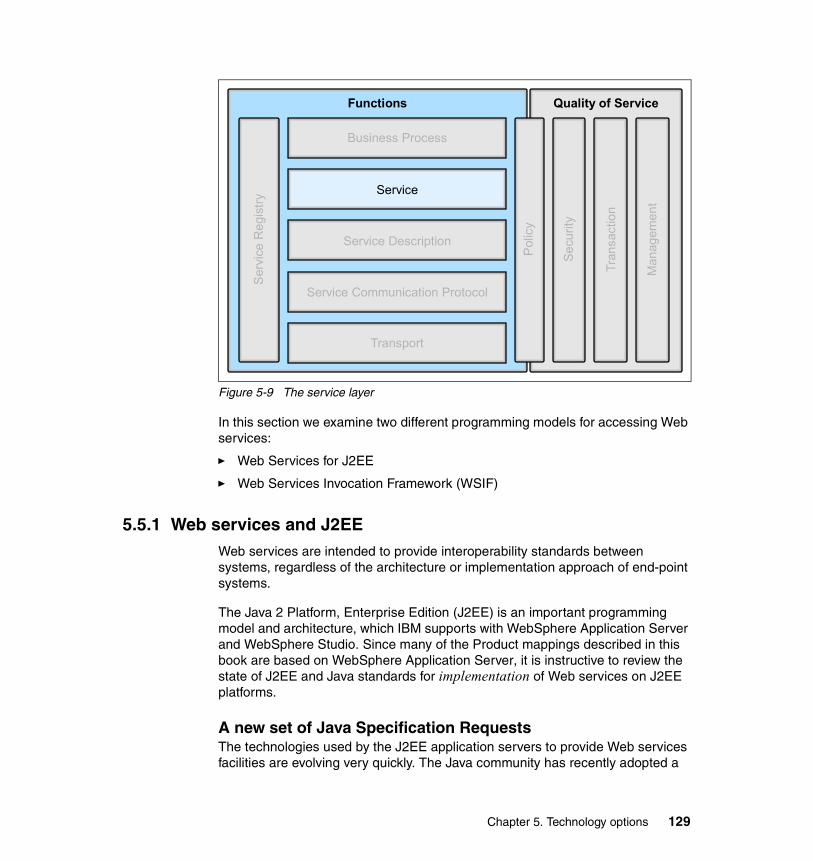
Figure 5-9 The service layer
In this section we examine two different programming models for accessing Web services:
� Web Services for J2EE
� Web Services Invocation Framework (WSIF)
5.5.1 Web services and J2EEWeb services are intended to provide interoperability standards between systems, regardless of the architecture or implementation approach of end-point systems.
The Java 2 Platform, Enterprise Edition (J2EE) is an important programming model and architecture, which IBM supports with WebSphere Application Server and WebSphere Studio. Since many of the Product mappings described in this book are based on WebSphere Application Server, it is instructive to review the state of J2EE and Java standards for implementation of Web services on J2EE platforms.
A new set of Java Specification RequestsThe technologies used by the J2EE application servers to provide Web services facilities are evolving very quickly. The Java community has recently adopted a
Transport
Business Process
Service Communication Protocol
Service Description
Service
Serv
ice
Reg
istry
Polic
y
Secu
rity
Tran
sact
ion
Man
agem
ent
Functions Quality of Service
Chapter 5. Technology options 129

set of standards to define the different aspects of how Web services can be supported in a J2EE-compliant application server.
These standards are described as Java Specification Requests (JSRs). JSRs are used as the tracking mechanism for all Java specifications, from proposal through to acceptance or rejection. Information about the Java Community Process, which manages the development of specifications, and the JSRs themselves, can be found at:
http://jcp.org
The main JSR concerning this domain is JSR 109, Implementing Enterprise Web Services (also known as Web Services for J2EE). It reached the final release status in November 2002.
The aim of JSR 109 is to define the programming model and runtime architecture for implementing Web services in Java. It federates the work done on several other JSRs. This JSR was led by IBM.
In much the same way that servlets tied together a set of concepts like cookies and HttpSession; and EJBs tied together techniques such as RMI, JTA/JTS, JDBC, and so on with a programming model and runtime model; the promoters of this JSR view it as doing the same for implementing and using Web services.
The Web Services for J2EE 1.0 specification is an addition to J2EE 1.3. J2EE 1.4 and requires support for Web Services for J2EE 1.1. There are minor differences between the J2EE 1.3 version (JSR-109 1.0) and the J2EE 1.4 version (JSR-109 1.1).
Specifications have also been opened for defining APIs to specific parts of the Web services stack:
� JSR 67: Java APIs for XML Messaging
JAXM provides an API for packaging and transporting business transactions using on-the-wire protocols being defined by ebXML.org, OASIS, W3C, and IETF.
� JSR 93: Java APIs for XML Registry
JAXR provides an API for a set of distributed registry services that enable business-to-business integration between business enterprises, using the protocols being defined by ebXML.org, OASIS, and ISO 11179.
� JSR 101: Java APIs for XML-Based RPC
JAX-RPC defines APIs to support emerging industry XML-based RPC standards.
130 Patterns: Service-Oriented Architecture and Web Services

� JSR 110: Java APIs for WSDL
This JSR provides a standard set of APIs for representing and manipulating services described by WSDL documents. These APIs define a way to construct and manipulate models of service descriptions.
Introduction in WebSphere Application ServerSupport for JSR 109 and the other related JSRs first appeared in WebSphere Application Server V5.0 as technology previews. IBM WebSphere Application Server V5.1 provides a more complete implementation, in addition to the Web services components that were available previously.
Supported standardsThe following standards are supported by the Web Services for J2EE component of IBM WebSphere Application Server V5.1:
� SOAP 1.1
� WSDL 1.1
� Web Services for J2EE (JSR-109) 1.0
� Java API for XML-Based RPC (JAX-RPC) 1.0
� SOAP with Attachments API for Java (SAAJ) 1.1
SOAP considerationsApache SOAP 2.3 shipped with WebSphere Application Server V4.0 and V5.0. It continues to co-exist with Web Services for J2EE. Apache SOAP is a proprietary API, and applications written for it are not portable to other SOAP implementations. Applications written for Web Services for J2EE should be portable to any vendor's implementation that supports Web Services for J2EE.
The Web services technology preview in WebSphere V5.0 leveraged the work that IBM contributed to the Apache Axis code base. The Web Services for J2EE support included with WebSphere V5.0.2 is derived from Apache Axis, but has diverged and contains many IBM-specific features to enhance performance, scalability, reliability, interoperability, and integration with the WebSphere Application Server.
The Apache SOAP channel and the SOAP/HTTP channel both support SOAP applications that are SOAP 1.1 compatible (for example, Apache SOAP 2.3 and Axis SOAP 1.0). So if you have an application that uses a production-supported Axis 1.0 SOAP stack, generating SOAP 1.1, then this application can use either channel.
If you are using the Apache SOAP channel, then the SOAP message format must be RPC style. To handle document style SOAP messages, you must use
Chapter 5. Technology options 131
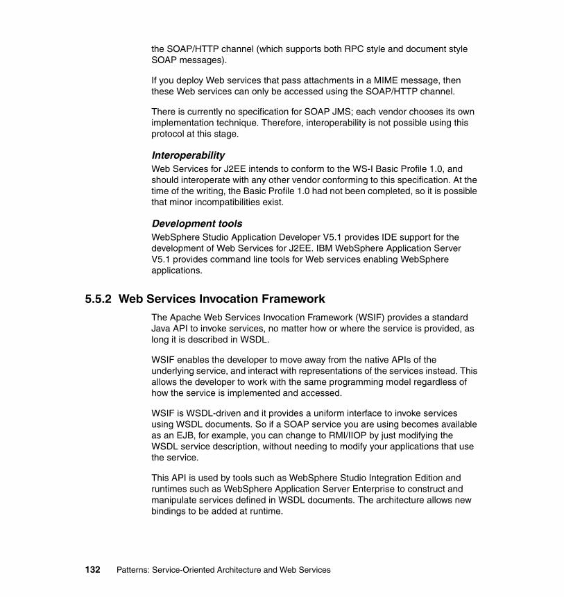
the SOAP/HTTP channel (which supports both RPC style and document style SOAP messages).
If you deploy Web services that pass attachments in a MIME message, then these Web services can only be accessed using the SOAP/HTTP channel.
There is currently no specification for SOAP JMS; each vendor chooses its own implementation technique. Therefore, interoperability is not possible using this protocol at this stage.
InteroperabilityWeb Services for J2EE intends to conform to the WS-I Basic Profile 1.0, and should interoperate with any other vendor conforming to this specification. At the time of the writing, the Basic Profile 1.0 had not been completed, so it is possible that minor incompatibilities exist.
Development toolsWebSphere Studio Application Developer V5.1 provides IDE support for the development of Web Services for J2EE. IBM WebSphere Application Server V5.1 provides command line tools for Web services enabling WebSphere applications.
5.5.2 Web Services Invocation FrameworkThe Apache Web Services Invocation Framework (WSIF) provides a standard Java API to invoke services, no matter how or where the service is provided, as long it is described in WSDL.
WSIF enables the developer to move away from the native APIs of the underlying service, and interact with representations of the services instead. This allows the developer to work with the same programming model regardless of how the service is implemented and accessed.
WSIF is WSDL-driven and it provides a uniform interface to invoke services using WSDL documents. So if a SOAP service you are using becomes available as an EJB, for example, you can change to RMI/IIOP by just modifying the WSDL service description, without needing to modify your applications that use the service.
This API is used by tools such as WebSphere Studio Integration Edition and runtimes such as WebSphere Application Server Enterprise to construct and manipulate services defined in WSDL documents. The architecture allows new bindings to be added at runtime.
132 Patterns: Service-Oriented Architecture and Web Services

For more details on the Web Services Invocation Framework see:
http://ws.apache.org/wsif/
Advantages of WSIFWSIF has the following advantages:
� Multiple bindings can be offered for services, and bindings can be decided at runtime.
� Services can be used either by a set of stub classes (static) or by a dynamic interface invocation (dynamic).
� You have the flexibility to switch protocols, location, etc., without having to recompile your client code.
Disadvantages of WSIFWSIF is a Java API, and so cannot be used in environments that are not based on Java.
5.6 Business processUsing industry standards, Web services can advertise their interfaces, be discovered and invoked upon, and communicate with each other to deliver end-to-end functionality. But to support the business process, a further level of abstraction is required. The business process layer in our architectural stack, shown in Figure 5-10 on page 134, allows us to create and define complex processes or workflows. Processes are composed from the operations supplied by Web services that can be nested and sequenced according to business requirements.
Chapter 5. Technology options 133

Figure 5-10 The business process layer
By isolating the business process from the implementation of the underlying Web services, as shown in Figure 5-11 on page 135, you can more readily adapt to changing business conditions.
Transport
Business Process
Service Communication Protocol
Service Description
Service
Serv
ice
Reg
istry
Polic
y
Secu
rity
Tran
sact
ion
Man
agem
ent
Functions Quality of Service
134 Patterns: Service-Oriented Architecture and Web Services

Figure 5-11 Isolating the business process from the implementation
Using a consistent modeling approach simplifies communication between all parties involved in the business process. In addition, models can be shared between partners without dictating the development tools or run-time environment that each of the partners in the process must use. A consistent modeling approach based on open standards also allows the activities in the process to be loosely coupled to the process itself, thereby minimizing the time and effort required to implement changes to the process as the business environment or requirements change.
5.6.1 WSFL and XLANGBoth the Web Services Flow Language (WSFL) from IBM and Microsoft XLANG were early suggestions for business process execution standards. These both have been combined and further developed to create a common standard backed by most of the current industry leaders as BPEL4WS, which is described in further detail in “Emerging standards for business process” on page 136.
Business Process Architecture
Component Architecture
Service Architecture
Chapter 5. Technology options 135

Process ChoreographerIBM WebSphere Application Server Enterprise V5.0 a provides a facility called the Process Choreographer. Business processes are described using a subset of the Web Services Flow Language (WSFL), an IBM specification that was developed before any standards work commenced on business process descriptions for Web services. A development plugin for WebSphere Studio Integration Edition may be used for process development. More information about Process Choreographer is available from:
http://www.software.ibm.com/wsdd/zones/was/wpc.html
See also IBM Redbook Patterns: Serial and Parallel Processes for Process Choreography and Workflow, SG24-6306.
Advantages of Process ChoreographerThere are a number of advantages to commencing the development of business processes using Process Choreographer, without waiting for products based on the new standards to be released. These include:
� You can start to develop experience with building business processes.
� You can develop processes that compose activities that are implemented as Web services, as J2EE components, as existing enterprise applications, and as manual activities.
Disadvantages of Process ChoreographerSince Process Choreographer does not currently implement open standards, there are some disadvantages in using it, including:
� You will have to migrate processes at some stage to standards based implementations. Note that it is likely IBM will provide tools to assist with this migration.
� Your business process developers will most likely have to learn changes to the development tools in support of a standards implementation.
� Any process activities that do not have a Web services interface will not be usable as activities in a standards-based implementation.
5.6.2 Emerging standards for business processAs already mentioned above, the proposals developed by individual vendors such as IBM and Microsoft in the past to create a business process execution standard, have been combined and further developed. As such there is currently only one major standard emerging to satisfy the requirements of the business process layer of our Web services stack.
136 Patterns: Service-Oriented Architecture and Web Services

BPEL4WSThe Business Process Execution Language for Web Services (BPEL4WS) provides a standard way of describing business processes that are based on Web services. Existing standards, such as WSDL, do not provide facilities that are required in complex business protocols, such as the description of behavior dependent on data sent between services, exception management and recovery, and coordination between business partner participants for long running and complex processes. BPEL4WS aims to meet these requirements.
BPEL4WS was first specified in July 2002 by BEA, IBM, Microsoft, SAP, and Siebel. The specification was constructed to combine the approaches previously described by Microsoft (XLANG, for the BizTalk server) and IBM (Web Services Flow Language, or WSFL). The latest release of the specification at the time of writing, version 1.1, was submitted to the OASIS standards group in May 2003. A copy of the standard is available from:
http://www.ibm.com/developerworks/webservices/library/ws-bpel/
You should note that the World Wide Web Consortium (W3C) has established a working group to develop the Web Services Choreography Interface (WSIC), which may provide an alternative standard. However, at the time of writing no draft had been issued.
At the time of writing, support for BPEL4WS is emerging in some products and technology previews. IBM provides BPWS4J as a runtime engine for WebSphere Application Server and Apache Tomcat. The BPWS4J toolkit also includes a development tool. BPWS4J can be downloaded from:
http://www.alphaworks.ibm.com/tech/bpws4j
IBM also provides a technology preview of a development plug-in for WebSphere Studio Integration Edition, as illustrated in Figure 5-12 on page 138.
Chapter 5. Technology options 137

Figure 5-12 BPEL4WS Importer/Exporter Technology Preview
This plug-in provides facilities to develop process flows using a visual editor, and generate WSDL files and other artifacts necessary to implement the process.
Implementations of the BPEL4WS standard may be appropriate Product mappings, particularly for the Extended Enterprise business pattern and the Application Integration pattern. However, the use of BPEL4WS technologies is not evaluated in this book.
For additional details, you may wish to review the following documents:
http://www.ibm.com/developerworks/webservices/library/ws-bpelwp/http://www.ibm.com/developerworks/webservices/library/ws-autobp/http://www.ibm.com/developerworks/webservices/library/ws-bpelcol1/
The last reference is the first in a series of columns that describe BPEL4WS at version 1.0 of the standard.
138 Patterns: Service-Oriented Architecture and Web Services

5.7 Service registryThe service registry layer in our architectural stack, shown in Figure 5-13, allows service providers to publish the definition of the services they offer using WSDL and service consumers to find information about the services available.
Figure 5-13 The service registry layer
In Web services architectures, the UDDI registry is typically mentioned in this role. The UDDI registry is often compared to the Yellow Pages of a telephone system. However, this approach overlooks some other complementary ways to provide the information needed to exploit available services.
Continuing with the telephone system analogy, let us look at some of the alternatives:
� Direct request
When you need to know the telephone number of a person, one of the easiest ways to get it is to request it from that person directly. That is very often the way to get the mobile number of a person because telephone directories rarely list mobile phone numbers.
� Simple aggregate publishing
When business people meet, they often exchange business cards. Business cards are a way to provide telephone numbers and additional information, such as fax numbers, e-mail addresses, and so on. Of course, you need to
Transport
Business Process
Service Communication Protocol
Service Description
ServiceSe
rvic
e R
egis
try
Polic
y
Secu
rity
Tran
sact
ion
Man
agem
ent
Functions Quality of Service
Chapter 5. Technology options 139

have them printed in the first place, which adds some complexity over the direct request solution.
� Directory use
It is only on some occasions that people refer to Yellow Pages; for example, to discover a service provider in a domain they are not familiar with. The Yellow Pages Directory provides more information than the other methods but requires a large effort to centralize information and publish it.
Similarly for Web services, you can use simple to complex discovery mechanisms to satisfy various business needs:
� The exchange of a service description on anything from an e-mail to a diskette can be compared to a direct request.
� WS-Inspection Language can be compared to business cards.
� The UDDI registries can be compared to Yellow Pages.
Figure 5-14 summarizes this discussion. This figure was adapted from Web Services Conceptual Architecture Version 1.0, available at:
http://www.ibm.com/software/solutions/webservices
Figure 5-14 Service discovery continuum
5.7.1 Static and dynamic Web services
The ultimate aim of a fully automated service-oriented information system, an on demand system, is to provide up-to-the minute discovery and bind to services.
High Function
Simple
Static Find Dynamic Find
e-mail, FTP, HTTP GET
Microsoft DISCO/ADS
WSDL-RepositoryWS-Inspection Language
UDDI(Private or Operator)
140 Patterns: Service-Oriented Architecture and Web Services

However, this fully automated model is not yet the prevailing one either at build time or at run time.
There are two ways of binding to Web services: Static and dynamic.
� In the static process, the binding is done at design time. The service consumer obtains a service interface and implementation description through a proprietary channel from the service provider (by e-mail, for example), and stores it in a local configuration file. No private, public, or shared UDDI registry is involved.
This process is well adapted to the development environment. It has the drawback that is makes it more difficult to receive information on the latest status of the service over time.
� The dynamic binding occurs at runtime. While the client application is running, it dynamically locates the service using a UDDI registry and then dynamically binds to it using WSDL and SOAP.
This requires that the contents of the UDDI registry be trusted as well as the service provider. Currently, only private UDDI networks can provide such control over the contents.
5.7.2 UDDIThe main current standard for services registries is the Universal Discovery Description and Integration standard defined by the UDDI organization, which is part of the OASIS organization, and is intended to act as an information broker between the service consumers and the service providers. At the time of writing this book, the latest version of the standard is version 3.
UDDI specifies the way to store and retrieve information about services and especially the provider name and the technical interfaces.
UDDI registry structureThere are several types of information stored in a UDDI structure. As shown in Figure 5-15 on page 142, this includes four primary data types:
� businessEntity, describing the service provider
� businessService, containing non-technical information about a service
� bindingTemplate, containing technical information to access the service (for example, URL, and may map to a WSDL document port)
� tModel, or technical model
Chapter 5. Technology options 141

Figure 5-15 Main UDDI data types
Figure 5-16 highlights the links between UDDI entries in a WSDL document.
Figure 5-16 WSDL to UDDI mapping
businessEntity
businessService
bindingTemplate
bindingTemplate
businessService
bindingTemplate
tModel
tModel
tModel
tModel
<definitions...><types...><import...><message...><porttype...><binding...>
</definitions>
<definitions...><import...><service...>
<port...><port...>
</service></definitions>
ServiceImplementation
Definition
ServiceInterfaceDefinition tModel
businessEntity
businessService
bindingTemplate
bindingTemplate
WSDL Description UDDI Description
142 Patterns: Service-Oriented Architecture and Web Services

Types of UDDI registriesThere are three main types of UDDI registries that deal with different business paradigms:
� UDDI operator cloud node
A public implementation of the UDDI standard is the UDDI Business Registry, or UBR. The UBR consists of several UDDI nodes. These nodes are managed by companies such as IBM, Microsoft, SAP and NTT. When a service provider wants to publish its services, they go to one of the UBR Web sites and register and publish their services. The data is then replicated to all the nodes in the UBR. For an example of a UBR, see:
http://uddi.ibm.com
The initial UDDI standard was focused on a multi-node public UBR. In addition to the description of services, it deals extensively with the replication and management issues of a multi-node environment.
This registry supports the claim of universal Web services discovered at run time.
At the time of writing this book, the UBR contains a limited number of entries. Among those entries very few are real Web services. Most entries are descriptions of businesses.
� Group or partner registries
These implementations focus on a specific number of known partners, generally from the same industry, to focus on really needed services and tackle the issue of confidence between providers and consumers.
� Private registries
Most companies tend to start Web services projects using an internal (private) UDDI registry.
Service discovery with UDDI registriesIn addition to storing information about services in an orderly manner, UDDI registries provide a search tool that allows for easy discovery of services:
� For example, all the services provided by a given business entity.
� Listing of services according to various categorizations.
5.7.3 Emerging standards for service registryThe only emerging standard currently under development for service registry is WS-Inspection.
Chapter 5. Technology options 143

WS-InspectionThe WS-Inspection specification, developed by IBM and Microsoft, allows the inspection of services offered at a site using an XML document made available at the point-of-offering. It provides a format for listing references to service description documents that have been authored in any number of formats. It also defines a set of conventions making it easy to locate WS-Inspection documents.
For more information on WS-Inspection see IBM Redbook, WebSphere Version 5.1/Application Developer 5.1.1 Web Services Handbook, SG24-6891.
5.8 PolicyPolicy has both functional and quality of service aspects in our architectural stack, as shown in Figure 5-17.
Figure 5-17 The policy layer
5.8.1 Emerging standards for policyThe WS-Policy framework is a metadata framework for describing quality of service (QoS) requirements and capabilities associated with services.
Transport
Business Process
Service Communication Protocol
Service Description
Service
Serv
ice
Reg
istry
Polic
y
Secu
rity
Tran
sact
ion
Man
agem
ent
Functions Quality of Service
144 Patterns: Service-Oriented Architecture and Web Services

The WS-Policy element in the Web services security roadmap provided by IBM and Microsoft in April 2002 has been further refined to include four documents:
� A Policy Framework (WS-Policy) document that defines a grammar for expressing Web services policies
� A Policy Attachment (WS-PolicyAttachment) document that defines how to attach these policies to Web services
� A set of general policy assertions (WS-PolicyAssertions)
� A set of security policy assertions (WS-SecurityPolicy)
WS-Policy is designed to allow extensibility. Policy is a broad term covering not only security, but other domains such as reliability, transactions, privacy, and so on. Each domain requires a language that lays out the available policy assertions for the domain, such as WS-SecurityPolicy for security.
In the future, WS-Policy should allow the selection of service providers based on their published capabilities. Service consumers could also use WS-Policy to publish their capabilities and requirements, allowing matching of compatible service consumers and providers.
Using the Enterprise Service Bus vision introduced in 2.4, “Enterprise Service Bus” on page 38, service consumers and providers could publish their policy requirements and capabilities to the ESB. The ESB could then identify the mediations needed in the request flow to meet the QoS requirements of each; for example, by setting message context (such as transaction IDs) and message security (such as encryption).
Where to find more informationFor more information on WS-Policy, see the following articles on IBM developerWorks:
� Web Services Policy Framework (WSPolicy) specification at:
http://www.ibm.com/developerworks/library/ws-polfram/
� Web Services Security: Moving up the stack, New specifications improve the WS-Security model at:
http://www.ibm.com/developerworks/webservices/library/ws-secroad/
5.9 SecurityIn the world of e-business, we rely heavily on the exchange and transport of data between a number of dispersed systems and applications, both within the enterprise and across organizational boundaries to business partners, suppliers
Chapter 5. Technology options 145

and customers. Whenever we need to package and exchange data, there is an inherent risk that during the time the data is traveling between its source and target application it can be intercepted and therefore stolen or modified. This threat is inherently high in a distributed architecture such as Web services, where transactions between a service consumer and the service provider are conducted using plain XML included in a SOAP message. This means that anyone that manages to intercept the transaction could easily read the data included within the SOAP payload. The security layer of the architectural stack, as shown in Figure 5-18, was included to secure Web services against these types of threats.
Figure 5-18 The security layer
In any architectural solution, the following security requirements must be addressed, with no exceptions when it comes to Web services:
� Identification: The party accessing the resource is able to identify itself to the system.
� Authentication: There exists a procedure to verify the identity of the accessing party.
� Authorization: There exists a set of transactions the authenticated party is allowed to perform.
� Integrity: The information is not changed on its way.
� Confidentiality: Nobody is able to read the information on its way.
Transport
Business Process
Service Communication Protocol
Service Description
Service
Serv
ice
Reg
istry
Polic
y
Secu
rity
Tran
sact
ion
Man
agem
ent
Functions Quality of Service
146 Patterns: Service-Oriented Architecture and Web Services

� Auditing: All transactions are recorded so that problems can be analyzed after the fact.
� Non-repudiation: Both parties are able to provide legal proof to a third party that the sender did send the information, and the receiver received the identical information.
Most of the systems implemented using Web services today only partially fulfill these requirements, either due to lack of standards or stable technologies.
In April 2002, IBM and Microsoft proposed a technical strategy and roadmap for “addressing security within a Web service environment.” The Web services security (WS-Security) specifications define a comprehensive Web service security model that supports, integrates and unifies several popular security models, mechanisms, and technologies (including both symmetric and public key technologies) in a way that enables a variety of systems to securely interoperate in a platform- and language-neutral manner.
The WS-Security specification provides a broad set of specifications that cover security technologies including authentication, authorization, privacy, trust, integrity, confidentiality, secure communications channels, federation, delegation, and auditing across a wide spectrum of application and business topologies. These specifications provide a framework that is extensible, flexible, and maximizes existing investments in security infrastructure. By leveraging the natural extensibility that is at the core of the Web services model, the specifications build upon foundational technologies such as SOAP, WSDL, XML Digital Signatures, XML Encryption, and SSL/TLS.
As shown in Figure 5-19 on page 148, this set includes a message security model (WS-Security) that provides the basis for the other security specifications. Layered on this, we have a policy layer that includes a Web service endpoint policy (WS-Policy), a trust model (WS-Trust), and a privacy model (WS-Privacy). Together these initial specifications provide the foundation upon which we can work to establish secure interoperable Web services across trust domains.
Chapter 5. Technology options 147

Figure 5-19 The evolving WS-Security roadmap
For more information, see the IBM developerWorks article Security in a Web Services World: A Proposed Architecture and Roadmap:
http://www.ibm.com/developerworks/webservices/library/ws-secmap/
As already identified, the landscape of Web services security is still being defined, and although new standards are continually being developed and deployed, the ways to achieve security with Web services today is at the following levels:
� At the transport level
At the transport level, Web services are secured by using the in-built security features of transport channel technologies such as HTTPS.
� At the service communication protocol level
Although constantly evolving with new specifications being developed, Web services security at this level is ensured using SOAP message based security.
� At the service description level
With XML document exchange as one of the fundamental components of Web services, it stands to reason that another level of security can be achieved at the service description level through the use of current XML-based security technologies such as digital signatures and encryption.
TodayTi
me
WS-SecureConversation WS-Federation
WS-Policy WS-Trust WS-Privacy
WS-Security
SOAP Foundation
WS-Authorization
148 Patterns: Service-Oriented Architecture and Web Services
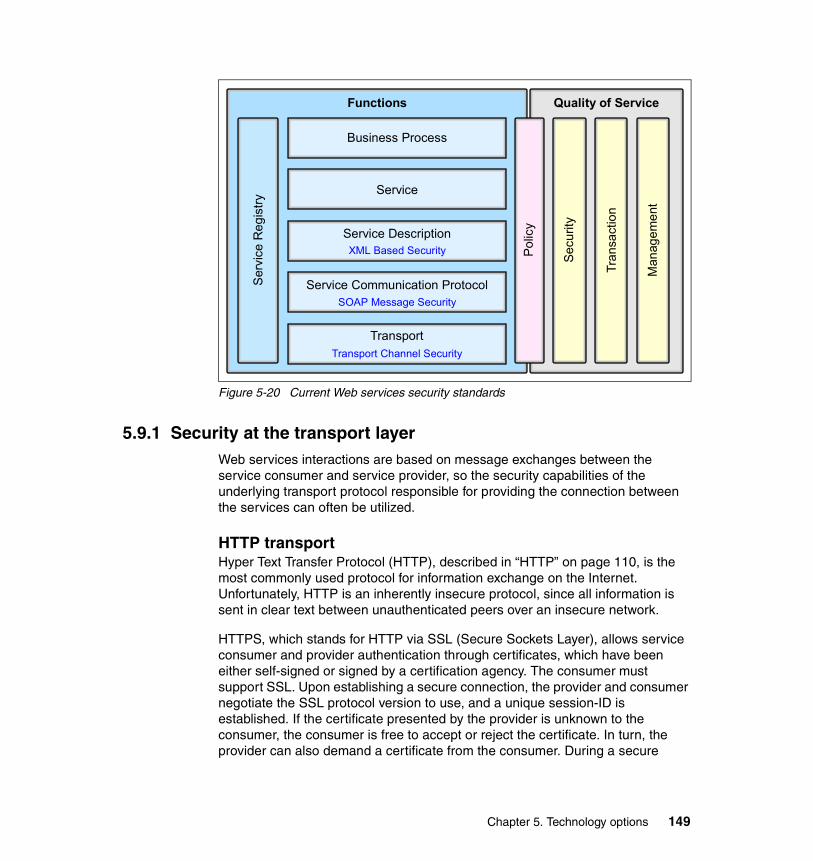
Figure 5-20 Current Web services security standards
5.9.1 Security at the transport layerWeb services interactions are based on message exchanges between the service consumer and service provider, so the security capabilities of the underlying transport protocol responsible for providing the connection between the services can often be utilized.
HTTP transportHyper Text Transfer Protocol (HTTP), described in “HTTP” on page 110, is the most commonly used protocol for information exchange on the Internet. Unfortunately, HTTP is an inherently insecure protocol, since all information is sent in clear text between unauthenticated peers over an insecure network.
HTTPS, which stands for HTTP via SSL (Secure Sockets Layer), allows service consumer and provider authentication through certificates, which have been either self-signed or signed by a certification agency. The consumer must support SSL. Upon establishing a secure connection, the provider and consumer negotiate the SSL protocol version to use, and a unique session-ID is established. If the certificate presented by the provider is unknown to the consumer, the consumer is free to accept or reject the certificate. In turn, the provider can also demand a certificate from the consumer. During a secure
Transport
Business Process
Service Communication Protocol
Service Description
Service
Serv
ice
Reg
istry
Polic
y
Secu
rity
Tran
sact
ion
Man
agem
ent
Functions Quality of Service
XML Based Security
SOAP Message Security
Transport Channel Security
Chapter 5. Technology options 149

session, the provider and consumer share a common key pair that allows them to encrypt and decrypt messages they exchange.
Although HTTPS does not cover all the aspects of general security framework, it provides a sufficient security level regarding party identification and authentication, message integrity, and confidentiality. However, authorization, auditing, and non-repudiation are not provided. Also, it is protocol-based and therefore all the security disappears once the message has passed the HTTP server. In addition, the encryption is message-wise and not element-wise; to access the routing information, we have to decrypt the entire message.
5.9.2 Security at the service communication protocol layerWhen trying to secure a SOAP message, two types of threats should be considered:
� The message could be modified or read by unauthorized persons.
� An unauthorized person could send messages to a service that, while well-formed, lacks appropriate security claims to warrant processing.
The WS-Security specification addresses these threats.
WS-SecurityWeb Services Security (WS-Security) Version 1.0 was jointly developed by IBM, Microsoft, and VeriSign, and was released in April 2002. It was submitted to OASIS by 18 companies, and now involves over 50 companies.
WS-Security describes SOAP messaging enhancements for protecting messages by encrypting and/or digitally signing the body, headers, attachments, and any combination or part thereof. This specification defines how to attach and include security tokens, such as X.509 certificates, within SOAP messages.
For more information, see the IBM developerWorks article Web Services Security (WS-Security):
http://www.ibm.com/developerworks/webservices/library/ws-secure/
5.9.3 Security at the service description layerSo far, we have discussed Web services security provided by the underlying transport (HTTP/S) and service communication protocol (SOAP) layers. We have already mentioned that Web services are about XML document exchange and therefore another level of security can be achieved at the XML document level. In this section we provide a brief overview of a set of security technologies that are being adopted as standards or are in the process of adoption.
150 Patterns: Service-Oriented Architecture and Web Services

XML digital signaturesXML digital signatures is a standard for securely verifying the origins of messages. It specifies a standard procedure for signing XML documents with a variety of different digital signature algorithms. Digital signatures can be used for validation of messages as well as for non-repudiation.
XML encryptionXML encryption is still a work in progress. Its aim is to allow encryption of digital content, such as GIF images or XML fragments. XML encryption allows the parts of an XML document to be encrypted while leaving other parts open, encryption of the XML itself, or the super encryption of data (that is, encrypting an XML document when some elements have already been encrypted).
Security assertion markup languageSecurity assertion markup language (SAML) is the first industry standard for secure e-business transactions based on XML. SAML is being developed to define a common way for sharing security services between companies engaged in business-to-business and business-to-consumer transactions. SAML allows companies to securely exchange authentication, authorization, and profile information among their customers, partners, or suppliers regardless of their security solutions or platforms. As a result, SAML supports the interoperability between different security systems.
5.9.4 Emerging standards for securityWe know that the Web services security standards still have some way to go, but ongoing development is addressing the gaps or short falls. The ability to implement Web services solutions that provide standards-based, enterprise-level security is not far from reach.
Extensions to the WS-Security specification are extending security coverage further up the functional and over to the non-functional components of the stack, as shown in Figure 5-21 on page 152.
Chapter 5. Technology options 151

Figure 5-21 Emerging Web services security standards
WS-SecureConversationWS-SecureConversation describes how to manage and authenticate message exchanges between parties, built on the concept of trust based on security tokens, including security context exchange and establishing and deriving session keys.
WS-FederationWS-Federation describes how to manage and broker the trust relationships in a heterogeneous federated environment, including support for federated identities.
WS-AuthorizationWS-Authorization describes how access policies for a Web service are specified and managed. In particular it describes how claims may be specified within security tokens and how these claims will be interpreted at the endpoint.
WS-PolicyWS-Policy describes the capabilities and constraints of the security (and other business) policies on intermediaries and endpoints. See also 5.8, “Policy” on page 144.
Transport
Business Process
Service Communication Protocol
Service Description
Service
Serv
ice
Reg
istry
Polic
y
Secu
rity
Tran
sact
ion
Man
agem
ent
Functions Quality of Service
WS-SecureConversation
Transport Channel Security
WS-
Polic
y
WS-
Fede
ratio
nW
S-Pr
ivac
yW
S-Au
thor
izat
ion
WS-
Trus
t
152 Patterns: Service-Oriented Architecture and Web Services

WS-TrustWS-Trust describes a framework for trust models that enables Web services to securely interoperate, by defining a set of interfaces that a secure token service may provide for the issuance, exchange, and validation of security tokens.
WS-PrivacyWS-Privacy describes a model for how Web services and requestors state privacy preferences and organizational privacy practice statements.
5.9.5 Where to find more informationBecause Web services security is a quickly evolving field, it is essential for developers and designers to regularly check for recent updates. In this section, we provide some important entry points for your exploration.
XML Signature Workgroup home page can be found at:
http://www.w3.org/Signature/
XML Encryption Workgroup home page can be found at:
http://www.w3.org/Encryption/
SAML (security assertions markup language) OASIS Security Services Technical Committee home page can be found at:
http://www.oasis-open.org/committees/security/docs/draft-sstc-use-strawman-03.html
For information on WS-Security, refer to the standard proposition overview on developerWorks:
http://www.ibm.com/developerworks/library/ws-secure/
The Web services security model proposition can be found at:
http://msdn.microsoft.com/library/default.asp?url=/library/en-us/dnwssecur/html/securitywhitepaper.asp
5.10 TransactionWhen using a distributed architecture such as Web services to automate business processes across the enterprise, the concept of transactions becomes very important. Figure 5-22 on page 154 shows transaction support as a quality of service layer in our architectural stack.
Chapter 5. Technology options 153

Figure 5-22 The transaction layer
A transaction, in the traditional definition, is a mechanism that insures all participants in a given environment (both business and technical) obtain an agreed upon outcome, such as a business transaction, financial transaction, or data transaction. These transactions have the following properties:
� Atomicity: If successful, then all the operations happen, and if unsuccessful, then none of the operations happen.
� Consistency: The application performs valid state transitions at completion.
� Isolation: The effects of the operations are not shared outside the transaction until it completes successfully.
� Durability: Once a transaction successfully completes, the changes survive failure.
5.10.1 Emerging standards for transactionTo facilitate these definitions within a Web services environment, the transaction layer of our stack contains the WS-Coordination and WS-Transaction standards. Although a Web services environment requires the same level of coordination and behavior defined for a traditional transaction, to control the outcomes of an operation, a more flexible approach is also required to handle transactions and outcomes from multiple services.
Transport
Business Process
Service Communication Protocol
Service Description
Service
Serv
ice
Reg
istry
Polic
y
Secu
rity
Tran
sact
ion
Man
agem
ent
Functions Quality of Service
154 Patterns: Service-Oriented Architecture and Web Services

It should be noted that both WS-Coordination and WS-Transaction are still regarded as emerging standards, and that further work to finalize the specifications are required.
WS-CoordinationWS-Coordination is a general purpose and extensible framework for providing protocols that coordinate the actions of distributed transactions. The defined framework enables an application service to create a context needed to propagate an activity to other services and to register for coordination protocols. The framework also enables existing transaction processing, workflow, and other systems for coordination to hide their proprietary protocols and to operate in a heterogeneous environment. It can be used with message sequencing and state machine synchronization.
WS-TransactionWS-Transaction includes support for the two types of transactions. It describes coordination types that are used with the extensible coordination framework as described in WS-Coordination. Two coordination types are defined: Atomic Transaction (AT) and Business Activity (BA). WS-Transaction is a building block used with other specifications (for example, WS-Coordination, WS-Security) and application-specific protocols that are able to accommodate a wide variety of coordination protocols related to the coordination actions of distributed applications.
Conversation Support for Web ServicesIBM is making available through alphaWorks® a technology called Conversation Support for Web Services (CS-WS) for supporting a conversational model of interaction between distributed, autonomous systems. The specification includes an XML dialect to describe a conversation interaction, called Conversation Policy (CP). CPs are preprogrammed interaction patterns that are used to specify the message formats, sequencing constraints, and timing constraints that define the interaction protocol. The other specifications in the set extend the J2EE Connector Architecture APIs, both at the system and application level, to provide a standard runtime framework to execute CPs on a J2EE application server.
5.10.2 Where to find more informationFor more information on transaction, see the following articles on IBM developerWorks:
� Web Services Coordination (WS-Coordination) at:
http://www.ibm.com/developerworks/library/ws-coor/
Chapter 5. Technology options 155

� Web Services Transaction (WS-Transaction) at:
http://www.ibm.com/developerworks/library/ws-transpec/
� Conversational Support for Web Services: The next stage of Web services abstraction at:
http://www.ibm.com/developerworks/library/ws-conver/
5.11 ManagementAs more and more businesses start to trust key parts of their operations to Web services, the management of these Web services becomes ever increasingly critical. In the case of our Web services architectural stack, as shown in Figure 5-23, the management layer is related to the ability to discover the existence, availability and health of the Web services infrastructure, service registries and Web service applications. Optimally, the management system should also be able to control and configure the infrastructure and components of the implemented SOA.
Figure 5-23 The management layer
But the quality of service aspects of management within the Web services architecture are broader than just the architectural stack, and must also include the management of the underlying infrastructure and networks required to implement and run the Web services. And furthermore, it must extend outside of
Transport
Business Process
Service Communication Protocol
Service Description
Service
Serv
ice
Reg
istry
Polic
y
Secu
rity
Tran
sact
ion
Man
agem
ent
Functions Quality of Service
156 Patterns: Service-Oriented Architecture and Web Services

the enterprise, to include integrated business partners, suppliers and customers. Only then can you ensure the management of the overall end-to-end Web services environment.
5.11.1 Emerging standards for managementThe OASIS organization has created a technical committee (TC) called Web Services Distributed Management (WSDM). There are two notable Web services management submissions to the WSDM TC:
� WS-Manageability, which is a joint submission by IBM, Talking Blocks, and Computer Associates. For information on WS-Manageability, see:
http://www.ibm.com/developerworks/library/ws-manage/
� Web Services Management Framework (WSMF), which is a joint submission by HP, Sun, BEA, IONA, TIBCO, Informatica, and webMethods. For information on WSMF, see:
http://devresource.hp.com/drc/specifications/wsmf/index.jsp
The OASIS Web Services Distributed Management Technical Committee home page can be found at:
http://www.oasis-open.org/committees/tc_home.php?wg_abbrev=wsdm
Chapter 5. Technology options 157

158 Patterns: Service-Oriented Architecture and Web Services

Chapter 6. HTTP service bus
This chapter describes the implementation of a simple supply chain management application on an HTTP service bus. The application is based on the WS-I Supply Chain Management (SCM) sample application, introduced in Chapter 4, “Service-oriented architecture approach” on page 79.
We deploy multiple instances of the Direct Connection application pattern, introduced in “Direct Connection application pattern” on page 52, to a Direct Connection runtime pattern using a HTTP service bus, as described in “Direct Connection using a service bus” on page 65.
In this chapter, the following topics are discussed:
� A recap of the sample business scenario that our solution needs to address.
� Design guidelines describing how the sample application shows appropriate design approaches for exposing services from applications.
� Development guidelines showing how development tools may be used to expose services and make them available on a service bus.
� Runtime guidelines discussing the considerations for deploying the applications and services.
� Best practices summarize the things you should consider when deploying a service bus.
6
© Copyright IBM Corp. 2004. All rights reserved. 159

6.1 Business scenarioThe sample application used in this chapter is a simplified supply chain for a consumer electronics retailer. Consumers may access the retailer’s Web site, review the catalog, and place orders for products (Self-Service business pattern). The retailer system requests fulfilment of a consumer’s order from company warehouses (Application Integration pattern), which respond as to whether line items from the order can be filled. If stock for any line item falls below a minimum threshold in any warehouse, a replenishment order is sent to the manufacturer (Extended Enterprise business pattern). The manufacturer will fulfil the replenishment order at some time; this process is asynchronous to the re-supply order.
As we saw in Chapter 4, “Service-oriented architecture approach” on page 79, our business scenario consists of a retailer, warehouse, logging facility, and three external manufactures, as shown in Figure 6-1.
Figure 6-1 High-level business context
The use cases defined for our business scenario are described in “Use case model” on page 86.
6.2 Design guidelinesThis section provides design guidelines for the sample application implemented on an HTTP service bus. In “Layered application architectures” on page 23 we
Browser
ConsumerRetailer
Inte
rnet
Inte
rnet
Organization boundary
Warehouse
Logging Facility
Manufacturer
160 Patterns: Service-Oriented Architecture and Web Services

briefly looked at structuring applications in service, component, and object layers.
The IBM developerWorks article, Using Service-Oriented Architecture and Component-Based Development to Build Web Service Applications, draws a number of important conclusions about best practices for designing service-oriented applications, including:
� Components do not necessarily make good services, just as objects do not necessarily make good components.
It is not a good practice to simply expose public object methods as services. One reason for this is that object methods tend to be fine grained, and exposing them as services would significantly increase cross-network communication to complete a business process.
� Patterns are available to construct effective services from components, and components from classes.
� Those patterns may be codified in tools to assist in the design and implementation process.
This section reviews design considerations for services, and to some degree components, from the application implementation layer model shown in Figure 2-5 on page 24.
For more information on this approach, see Using Service-Oriented Architecture and Component-Based Development to Build Web Service Applications, available at:
http://www.ibm.com/developerworks/rational/library/510.html
6.2.1 Design overviewIn Chapter 4, “Service-oriented architecture approach” on page 79, we developed the high-level solution overview for the WS-I SCM sample application, shown in Figure 6-2 on page 162, based on a service-oriented and Patterns for e-business approach. In this section we take a closer look at the Runtime patterns highlighted in Figure 6-2 on page 162, and Product mappings identified.
Chapter 6. HTTP service bus 161

Figure 6-2 Runtime patterns for the Supply Chain Management Sample
As discussed in “Applying Business and Application Integration patterns” on page 89, the sample application exhibits the following patterns:
� Self-Service business pattern for the consumer interaction with the retailer. This pattern is not described in this book. For more information, see IBM Redbook Patterns: Self-Service Application Solutions Using WebSphere Application Server V5, SG24-6591.
� Application Integration pattern for interactions between the retailer and the warehouse, and between these services and the logging facility. The implementation of the services on an HTTP service bus is an example of the Application Integration::Direct Connection runtime pattern, as shown in Figure 6-3 on page 163.
Web Server Redirector
Dom
ain
Fire
wal
l
Prot
ocol
Fire
wal
l
Inte
rnet
Dom
ain
Fire
wal
l
Enterprise Domain Partners
DMZ DMZInter-Enterprise
ZoneInternal NetworkOutside World
Stand-Alone Single Channel Application Pattern::Runtime Pattern: Variation 1
Direct Connection Application Integration
Pattern::Runtime Pattern
Retailer Service on this node
Manufacturer Service on Partner Infrastructure
Exposed Router Application
Pattern::Runtime Pattern
Connector
Prot
ocol
Fire
wal
l
Exposed Direct Connection Application
Integration Pattern::Runtime Pattern
Exposed Router
Rules Repository
Application Server / Services
Directory and Security Services
ConnectorApplication
Server / Services
Database
Application Server / Services
Rules RepositoryConnector
Partner Infrastructure
InterEnterprise Network
Infrastructure
Warehouse & Warehouse Callback Services on this node
Logging Service on this node
Service bus
162 Patterns: Service-Oriented Architecture and Web Services
Figure 6-3 Service bus with adapter connectors
We used both Windows and Linux systems in the HTTP service bus deployment. Figure 6-3 shows an example where a service consumer (retailer) interacts with two other service providers (warehouse and logging facility) using the HTTP service bus.
� Extended Enterprise business pattern for interactions between the warehouse and the manufacturers, and between the manufacturers and the logging facility. In this case, the implementation of the services is based on the Extended Enterprise::Exposed Direct Connection runtime pattern. This pattern, shown in Figure 6-4 on page 164, is used for both the replenish stock and supply finished goods use cases, which require a business interaction between the warehouse and the manufacturer services.
<Service Bus>SOAP 1.1 / HTTP 1.1
WebSphere Application Server V5.1
Windows 2000 + SP4
Internal network
App Server/Services
App Server/Services
App Server/Services
<Service Provider><Service Consumer> <Service Provider>
Adapter Connector
Adapter Connector
Adapter Connector
WebSphere Application Server V5.1
Red Hat Linux AS 2.1
JAX-
RPC
SOAP
Pro
vide
r
JAX-
RPC
SOAP
Pro
vide
r
Chapter 6. HTTP service bus 163

Figure 6-4 Exposed Direct Connection: Web services Product mapping
6.2.2 Service design considerationsThe WS-I sample application was primarily developed to illustrate the use of the WS-I Basic Profile. It was not specifically designed to illustrate Web services best practices, although some are exhibited in the sample application design. See “Best practices” on page 223 for further details.
Selecting the service interaction styleThe WS-I sample application, on which the implementation described in this book is based, implements three usage scenarios:
� One-way
� Synchronous request/response
� Basic callback
Table 6-1 on page 165 maps the WS-I usage scenarios to runtime patterns, and lists the sample application services that use each approach.
Partner ASecure Zone
Demilitarized Zone
Partner BInter- enterprise
Zone
Prot
ocol
Fire
wal
l
Dom
ain
Fire
wal
l
Network Infra-
structurePartner
Infrastructure
SOAP/HTTP
AdapterConnector
App Server/Services
Internet
WebSphere Application Server V5.1
Windows 2000 + SP4
JAX-RPC SOAP Provider
164 Patterns: Service-Oriented Architecture and Web Services

Table 6-1 Mapping the WS-I service usage scenarios to runtime patterns
Design alternative: One-way scenarioThe one-way scenario is defined for situations where the consumer needs to send a message to the provider, but does not need to know whether the provider received the message or what it did with it. The sample application LoggingFacility is used by all consumers to log events under the WS-I one-way messaging usage scenario, as shown in Figure 6-5 on page 166.
Runtime pattern WS-I usage scenario
Sample application uses
Application Integration::Direct Connection (message variation)
One-way Retailer -> LoggingFacility (logEvents)Warehouse -> LoggingFacility (logEvents)
Extended Enterprise::Exposed Direct Connection (message variation)
Manufacturer -> LoggingFacility
Since the logging facility is implemented in the secure zone of the retailer, this is an inter-enterprise implementation.
Note that there is no change to the logging facility implementation, by making it available as a Web service, it can be used by both internal and external applications.
Application Integration::Direct Connection (call variation)
Synchronous request/response
Consumer -> RetailerRetailer -> Warehouse
Basic callback
Extended Enterprise::Exposed Direct Connection (call variation)
Synchronous request/response
Basic callback Warehouse -> ManufacturerManufacturer -> WarehouseCallBack
Chapter 6. HTTP service bus 165

Figure 6-5 Example of a WS-I one-way scenario
The Figure 6-5 scenario is an example of the message variation of the Application Integration::Direct Connection runtime pattern. When the Manufacturer is the consumer of the Logging facility service, it is an example of the message variation of the Extended Enterprise::Exposed Direct Connection runtime pattern.
This one-way approach should be selected when the consumer needs to send information to the provider in a send and forget mode. When planning to use this scenario, you should carefully consider the quality of service requirements and in particular the reliability of the transport used to send the message. Since there is no reply from the provider, the consumer cannot know whether the provider received and processed the message. If the requirements specify that the message must be processed, consider either:
� Using a reliable transport, such as JMS or WS-ReliableMessaging
� Using a call variation, and including logic in the consumer to retry if a response message is not received
The reliable transport option should be preferred, since the tasks of tracking message delivery and recovering from failures to deliver messages are complex, and better suited to middleware which is designed for this purpose rather than application code.
Design alternative: Synchronous request/response scenarioThe synchronous request/response scenario is defined for situations where a consumer needs a response to a request. The consumer waits for a response from the provider. Figure 6-6 on page 167 provides an example.
166 Patterns: Service-Oriented Architecture and Web Services

Figure 6-6 Example of a WS-I synchronous request/response scenario
The Figure 6-6 scenario is an example of the call variation of the Application Integration::Direct Connection runtime pattern, since both the Retailer and Warehouse services are hosted in the secure network zone of the company.
This pattern should be selected when the requirements specify that a request must be responded to before the business process can continue. In the sample application, for example, it is not possible for the consumer to buy a product until they have been supplied with a catalog listing. So the business process to buy a product cannot continue until the requested catalog listing has been returned.
Quality of service attributes are important qualifiers on the selection of this scenario to meet a business requirement. The synchronous request/response scenario in a Web services environment will almost always suffer greater latency than request/response using other approaches, such as RPC. This is because:
� More components are required to implement this scenario for a Web services environment than, for example, an RPC environment.
� Since the data exchanges are in self-describing XML, there is a greater cost to parse and process the message exchanges than for serialized object data.
Design alternative: Basic callback scenarioThe basic callback scenario is provided for situations where a consumer needs a response to a request, but will not wait for the response, which might take some time for the provider to send. An example is shown in Figure 6-7 on page 168.
Chapter 6. HTTP service bus 167

Figure 6-7 Example of a WS-I basic callback scenario
The Figure 6-7 scenario can be implemented using two instances of the call variation of the Extended Enterprise::Exposed Direct Connection runtime pattern; one instance for the consumer request and one for the provider response. The Extended Enterprise pattern is used because the Warehouse and Manufacturer services are hosted in different secure network zones, and communicate over the Internet.
Describing the serviceIn developing the sample scenario, we assume that the WS-I defined each service required for the sample application in WSDL, after the use cases and message types had been defined. This is a top-down design approach.
Figure 6-8 on page 169 shows the relationships defined in the WSDL for an implementation of the Manufacturer service. We are using the WSDL Editor from WebSphere Studio Application Developer V5.1.1 for a concise view of the WSDL files. For the full listings, all WSDL files are packaged with our version of the sample application available on the Web; see Appendix B, “Additional material” on page 333, for details.
168 Patterns: Service-Oriented Architecture and Web Services

Figure 6-8 Example of Manufacturer WSDL structure
From the structure shown in Figure 6-8, we can see that:
� This WSDL file imports two other WSDL files, which define Manufacturer and configuration. These files are the WS-I definitions of the port types and message formats that the implemented Manufacturer service should provide. These import statements would normally refer to a network location; in this case we made a local copy of the WSDL files so we could examine them easily using the WSDL editor.
� Two port types are defined in this WSDL file. The ManufacturerPortType is provided by the Manufacturer service. The other port type is for use with the Warehouse callback service.
� One operation is defined on the port type, submitPO. This operation expects an input message of type POSubmit, which is composed of parts. Output and fault messages are also defined for the operation. Figure 6-9 on page 170 shows the details of the PurchaseOrder message.
Chapter 6. HTTP service bus 169

Figure 6-9 Purchase order message structure from Manufacturer WSDL file
Design alternative: Top down or bottom upIn the case of the sample application, the service interfaces were designed by WS-I first, and then the implementations were provided by various vendors, including IBM. This is an example of top-down design. Top-down design was considered in this case because:
� There were no existing systems or implementations when the decision was made to create the services. Therefore, restrictions imposed by existing system implementations did not have to be considered in the logical design of each service.
� The intent was to build interoperable services, with the facility to deploy any service on any system type. Therefore, WSDL could be developed to meet the interoperability goal, avoiding extensions or complex headers.
When using a top-down approach, you need to avoid:
� Making the service design too complex
� Being tempted to use all available features of WSDL or imported schemas
If you are in the situation where you have existing systems from which you wish to expose some Web services, you may need to consider a bottom-up approach. This means that the WSDL is generated from existing code, using facilities such as the WebSphere Studio Application Developer Web Service wizard. If you decide to use a bottom-up approach, the main issue which might arise is problems with interoperability. This means that the service may not be usable by intended consumers of the service, if you do not control those consumers. This is
170 Patterns: Service-Oriented Architecture and Web Services

because the generation tool may introduce elements into the WSDL that are artifacts of the underlying implementation, or features that are not interoperable. To mitigate this risk:
� Ensure that your WSDL generation tool provides options to generate WSDL that conforms to the WS-I Basic Profile. For example, Figure 6-10 shows the option in the WebSphere Studio Application Developer Web services wizard to specify an encoding style that is more likely to be interoperable.
Figure 6-10 WebSphere Studio WSDL generation options
An advantage of using WebSphere Studio Application Developer for this task is that it will generate a warning if you make a choice that might restrict interoperability. An example is shown in Figure 6-11 on page 172.
Chapter 6. HTTP service bus 171

Figure 6-11 WebSphere Studio WSDL generation warning
� Provide facilities for consumers to test their client applications against the service.
Design alternative: Separate interface and implementationAs discussed in 5.4.2, “WSDL” on page 123, the WSDL service description requires both interface information and implementation information. For the sample application, the interface WSDL was provided by WS-I. In order to implement the service, all that was required was to define the service and port information in an implementation WSDL file which imports the interface WSDL file.
Figure 6-12 shows the interface WSDL file for Manufacturer, as provided by WS-I.
Figure 6-12 Interface WSDL for Manufacturer
172 Patterns: Service-Oriented Architecture and Web Services

Note that the interface WSDL shown in Figure 6-12 on page 172 does not include any service definitions. Bindings, port types and message contents are defined, but the definition of the service is left to the service implementor.
Example 6-1 shows the implementation WSDL file.
Example 6-1 Manufacturer service implementation WSDL file
<?xml version="1.0" encoding="UTF-8"?><wsdl:definitions targetNamespace="http://www.ws-i.org/SampleApplications/SupplyChainManagement/2002-10/Manufacturer.wsdl" xmlns:tns="http://www.ws-i.org/SampleApplications/SupplyChainManagement/2002-10/Manufacturer.wsdl" xmlns:wsdl="http://schemas.xmlsoap.org/wsdl/" xmlns:wsdlsoap="http://schemas.xmlsoap.org/wsdl/soap/" xmlns:xsd="http://www.w3.org/2001/XMLSchema" xmlns:intf="http://www.ws-i.org/SampleApplications/SupplyChainManagement/2002-10/Manufacturer.wsdl">
<wsdl:import location="Manufacturer.wsdl" namespace="http://www.ws-i.org/SampleApplications/SupplyChainManagement/2002-10/Manufacturer.wsdl"/> <wsdl:import location="Configuration.wsdl" namespace="http://www.ws-i.org/SampleApplications/SupplyChainManagement/2002-08/Configuration.wsdl"/>
<wsdl:service name="ManufacturerService"> <wsdl:port binding="intf:ManufacturerSoapBinding" name="Manufacturer"> <wsdlsoap:address location="http://entsrv1w.itso.ral.ibm.com/Manufacturer/services/Manufacturer"/> </wsdl:port> </wsdl:service>
</wsdl:definitions>
From the implementation file, notice that:
� The interface WSDL is imported.
� The service is defined using the <wsdl:service> tag.
� The port is linked to the binding name defined in the interface file.
Chapter 6. HTTP service bus 173

There are a number of advantages of separating the interface and implementation files, including:
� It allows the interface definition to be reused for different implementations.
� Your WSDL development tool may not allow the definition of multiple ports for a service, requiring you to separate the implementations into different files.
You should be aware, however, that implementor of service consumers will require the implementation WSDL file in order to generate their client code.
Design alternative: Imbed or import data definitionsWithin your WSDL files, you need to define the messages produced and consumed by your service, and the types of the contents of those messages. You can define this information wholly within the WSDL file, or you can define it in schema files and import the schemas into the WSDL.
For the sample application, the type and message definitions were available in schema files and we chose to use those. An example of the import of types and message definitions is shown in an extract from the Manufacturer interface WSDL file shown in Example 6-2.
Example 6-2 Extract from Manufacturer WSDL showing imported message definitions
...<wsdl:types> <xs:schema elementFormDefault="qualified" attributeFormDefault="unqualified">...
<xs:import namespace="http://www.ws-i.org/SampleApplications/SupplyChainManagement/2002-10/ManufacturerPO.xsd" schemaLocation="ManufacturerPO.xsd"/>... </xs:schema></wsdl:types>...<wsdl:message name="POSubmit"> <wsdl:documentation> A purchase order. </wsdl:documentation> <wsdl:part name="PurchaseOrder" element="po:PurchaseOrder"/>...</wsdl:message>...
The alternative approach is to define types and messages within the WSDL, as shown in Example 6-3 on page 175.
174 Patterns: Service-Oriented Architecture and Web Services

Example 6-3 Extract from a simple WSDL showing imbedded message definitions
<wsdl:types> <schema elementFormDefault="qualified" targetNamespace="http://itso.ibm.com" xmlns="http://www.w3.org/2001/XMLSchema"> <element name="hello"> <complexType> <sequence/> </complexType> </element> <element name="helloResponse"> <complexType> <sequence> <element name="helloReturn" nillable="true" type="xsd:string"/> </sequence> </complexType> </element></schema></wsdl:types><wsdl:message name="helloResponse"> <wsdl:part name="parameters" element="intf:helloResponse"/></wsdl:message>
There are a number of trade-offs to be considered when deciding whether to import or imbed your message and type definitions, including:
� Defining messages separately from the interface or implementation files facilitates reuse of the message definitions in other service definitions.
� Changes to schema files may impact services that use those definitions, particularly if the implementor of the service or consumer has generated serialization code directly from the WSDL files. This means that once a data schema is published, altering it may have a big impact on users of services that use the schema.
� For any imports that refer to a network location, the network location must be available when performing operations such as designing WSDL files, starting services, and so on.
� Both runtime and development time products must support the use of imported schemas.
Selecting the service communication protocolAll the services in the sample application use SOAP as the service communication protocol. The purpose of the sample application is to demonstrate interoperability between services that conform to the WS-I Basic Profile, which includes SOAP 1.1. No alternatives to SOAP were considered for this reason.
Chapter 6. HTTP service bus 175

Alternatives that do exist include HTTP GET/POST carrying an XML message as a request string or request body, or MIME.
Something you should consider is whether to implement a Web service at all. For internal applications, Web services may be significantly more resource intensive than other integration mechanisms, such as remote procedure call or message based integration. In particular, XML parsing may be more resource intensive than a tighter coupling between applications.
Design alternative: Selecting the binding styleSOAP provides two binding styles, document and rpc. Both styles are used in the sample application to illustrate potential uses of these styles. For example, Manufacturer uses the document style, as shown in the extract from the WSDL file shown in Example 6-4.
Example 6-4 Extract from Manufacturer WSDL showing document style
<wsdl:binding name="ManufacturerSoapBinding" type="tns:ManufacturerPortType"> <wsdl:documentation> <wsi:Claim conformsTo="http://ws-i.org/profiles/basic1.0/"/> </wsdl:documentation> <soap:binding style="document" transport="http://schemas.xmlsoap.org/soap/http"/> <wsdl:operation name="submitPO"> <soap:operation/> <wsdl:input> <soap:body parts="PurchaseOrder" use="literal"/> <soap:header message="tns:POSubmit" part="ConfigurationHeader" use="literal"> <soap:headerfault message="cfg:ConfigurationFaultMessage" part="ConfigurationFault" use="literal"/> </soap:header> <soap:header message="tns:POSubmit" part="StartHeader" use="literal"/> </wsdl:input> <wsdl:output> <soap:body use="literal"/> </wsdl:output> <wsdl:fault name="POFault"> <soap:fault name="POFault" use="literal"/> </wsdl:fault> </wsdl:operation></wsdl:binding>
The Warehouse service, on the other hand, uses RPC style, as shown in Example 6-5 on page 177.
176 Patterns: Service-Oriented Architecture and Web Services

Example 6-5 Extract from Warehouse WSDL showing rpc style
<wsdl:binding name="WarehouseSoapBinding" type="tns:WarehouseShipmentsPortType"> <wsdl:documentation> <wsi:Claim conformsTo="http://ws-i.org/profiles/basic1.0/" /> </wsdl:documentation> <soap:binding transport="http://schemas.xmlsoap.org/soap/http" style="rpc"/> <wsdl:operation name="ShipGoods"> <soap:operation soapAction="http://www.ws-i.org/SampleApplications/SupplyChainManagement/2002-08/Warehouse.wsdl"/> <wsdl:input> <soap:body use="literal" namespace="http://www.ws-i.org/SampleApplications/SupplyChainManagement/2002-08/Warehouse.wsdl" parts="ItemList Customer" /> <soap:header message="tns:ShipGoodsRequest" part="ConfigurationHeader" use="literal"> <soap:headerfault message="c:ConfigurationFaultMessage" part="ConfigurationFault" use="literal" /> </soap:header> </wsdl:input> <wsdl:output> <soap:body use="literal" namespace="http://www.ws-i.org/SampleApplications/SupplyChainManagement/2002-08/Warehouse.wsdl"/> </wsdl:output> </wsdl:operation></wsdl:binding>
The RPC style assumes that the provider is a procedure, and the call to the service is a remote procedure call, where the consumer provides the call parameters in the SOAP body. The call parameters are wrapped in an element that specifies the procedure’s name. The document style makes no assumptions about how the provider will process the service call, which leaves more flexibility in the definition of the messages consumed by and produced by the service.
Considerations for deciding which style to use include:
� Advantages of RPC style
– It is simpler to write and provide services for RPC style. These services are more rigid in the message formats they use, and therefore less parsing and message analysis code is required in the application code than with
Chapter 6. HTTP service bus 177

document style, which may have to cater for more data and more combinations of document structure.
– RPC is a more natural style for interfacing to existing applications that already exist and use a synchronous call style (remote procedure call).
– Provides an XML interface to applications that do not have an XML interface today.
– Supported in older versions of application servers. For example, WebSphere Application Server V4 provides RPC style, but not document style.
� Advantages of document style
– Document style is more naturally suited to asynchronous processing and one-way scenarios.
– Changes to the message schema are less likely to break service consumers. Adding elements to messages, and reordering sequences in message definitions, are less likely to impact both consumers and providers.
– It is possible to add information to the XML document that is being exchanged between the consumer and provider for purposes other than the invocation of the service. In the RPC style, the message must be validated in order to invoke the target procedure. With document style, validation of additional elements can be deferred to a component of the implemented service.
– Microsoft tools for the creation of Web services tend to use the document style, so interoperability with service providers or consumers built on Microsoft platforms is more likely.
– Document style services tend to perform better than RPC style services. This is because the SOAP server has to perform validation with RPC style, whereas for document style the XML request is sent straight to the processing application.
A detailed discussion of the merits of document style is available from:
http://www.ibm.com/developerworks/webservices/library/ws-docstyle.html
Design alternative: Selecting the encoding styleTwo mechanisms for describing the body of a SOAP message are available, literal and encoded. The sample application services use only literal encoding, since the WS-I Basic Profile does not allow the use of encoded. For interoperable Web services, you should use literal. You need to ensure that both your development tools and runtime platform support literal encoding. The latest releases of WebSphere Studio Application Developer and WebSphere Application Server support this encoding style.
178 Patterns: Service-Oriented Architecture and Web Services

Some development tools and runtime environments, particularly older releases, use encoded style by default, and some do not support literal. If you are using older releases, you may need to use the encoded style. If this is the case in your environment, you will need to pay special attention to interoperability testing with potential partners.
Allowing consumers to locate the serviceA vital component of a service-oriented architecture is the approach used for finding and invoking services. Three main alternatives are available for service location, supplying the address in a WSDL file, using Web services inspection language (WSIL), or using a UDDI registry.
Design alternative: Specify location in WSDL fileThe simplest alternative for service location is to provide a WSDL file to consumers of the service. Example 6-6 shows the service location information in an extract from the Manufacturer WSDL file.
Example 6-6 Extract from Manufacturer WSDL file showing service location
<wsdl:service name="ManufacturerService"> <wsdl:port binding="intf:ManufacturerSoapBinding" name="Manufacturer"> <wsdlsoap:address location="http://entsrv1w.itso.ral.ibm.com/Manufacturer/services/Manufacturer"/> </wsdl:port> </wsdl:service>
The consumer uses the location to invoke the service. Tools such as WebSphere Studio can generate client stub code from the WSDL file. The approach used to generate the Warehouse client for the Manufacturer service is detailed in 6.3.4, “Service consumer (client) development considerations” on page 200.
Design alternative: Using WSILWSIL (or WS-Inspection) provides a light-weight service discovery mechanism without introducing the complexity of UDDI. For a full discussion on WSIL see the IBM Redbook WebSphere Version 5.1/Application Developer 5.1.1 Web Services Handbook, SG24-6891.
Design alternative: Using a UDDI registryThis alternative is discussed in detail in Chapter 8, “Service directory” on page 251.
Chapter 6. HTTP service bus 179

6.2.3 Component design considerationsThe availability of tools and wizards to generate Web services from almost any existing programming asset brings a number of risks that apply to bottom up implementations. For example, with bottom-up design, it is possible to:
� Expose details of the implementation of your business processes to consumers.
� Introduce unnecessary network communication which may result in latency and application performance that does not meet expectations.
You should review your approach to deployment of Web services to avoid these pitfalls.
Sample application component overviewThe sample application has a high-level deployment structure as shown in Figure 6-13.
Figure 6-13 Sample application deployment diagram
Each service is designed to be implemented independently of the others, and in this case some services have been co-located on a node due to:
� Amount of hardware available to implement the system.
� Performance and capacity plans might allow such a co-location.
180 Patterns: Service-Oriented Architecture and Web Services

The Manufacturer service is representative of how each service component is designed. Figure 6-14 shows the package hierarchy used by the Manufacturer service.
Figure 6-14 Package structure for Manufacturer service
Implementing services on a façadeThe façade pattern was introduced in the book Design Patterns: Elements of Reusable Object-Oriented Software, and is in common use in J2EE environments, particularly where session beans are used as a façade to hide the implementation of entities.
A façade hides the underlying implementation of a service, and presents only the interface that the service offers.
If you use a top-down approach with tools such as WebSphere Studio Application Developer, a façade may be generated for you. In the case of the sample application, a façade is implemented for each service. Public methods are only made available for the operations the service publishes. Figure 6-15 on page 182 shows selected classes from the Manufacturer service.
Chapter 6. HTTP service bus 181

Figure 6-15 Selected classes from Manufacturer service implementation
From Figure 6-15, observe that:
� The ManufacturerImpl class contains the main processing logic for the manufacturing service.
� The StockWorker class is delegated to handle incoming purchase orders.
� The PurchOrdType, ItemList, and Item classes handle the data received from the service call.
Please also note that Figure 6-15 shows only a subset of the classes that implement the Manufacturer service; in particular, the classes used to manage a shipping notice, send the shipping notice back to the warehouse that sent the original purchase order, and perform logging are not included. The classes that implement the Web service infrastructure are not described either, since these are provided for you through the Web service wizard.
The connection between the façade and the service is specified to the runtime environment (for example, WebSphere Application Server) using the Web services deployment descriptor (webservices.xml), as shown in Example 6-7 on page 183.
Manufacturerfaçade
182 Patterns: Service-Oriented Architecture and Web Services

Example 6-7 Web service deployment descriptor for Manufacturer service
<?xml version="1.0" encoding="UTF-8"?><!DOCTYPE webservices PUBLIC "-//IBM Corporation, Inc.//DTD J2EE Web services 1.0//EN" "http://www.ibm.com/webservices/dtd/j2ee_web_services_1_0.dtd"><webservices> <webservice-description> <webservice-description-name>ManufacturerService</webservice-description-name> <wsdl-file>WEB-INF/wsdl/Manufacturer_Impl.wsdl</wsdl-file> <jaxrpc-mapping-file>WEB-INF/Manufacturer_Impl_mapping.xml</jaxrpc-mapping-file> <port-component> <port-component-name>Manufacturer</port-component-name> <wsdl-port> <namespaceURI>http://www.ws-i.org/SampleApplications/SupplyChainManagement/2002-10/Manufacturer.wsdl</namespaceURI> <localpart>Manufacturer</localpart> </wsdl-port> <service-endpoint-interface>org.ws_i.www.ManufacturerPortType</service-endpoint-interface> <service-impl-bean> <servlet-link>org_ws_i_www_ManufacturerSoapBindingImpl</servlet-link> </service-impl-bean> </port-component> </webservice-description></webservices>
Note from Example 6-7 that the <service-endpoint-interface> tag describes the class we have described as the façade interface class, and the <servlet-link> tag describes the façade implementation class.
If you are using a bottom-up approach, you should consider implementing a façade and generating services from that. Tools such as Rational® XDE™ provide the facility to include “Gang of Four” (GoF) patterns, such as the façade, in your design.
Invoking the service from the consumerSo far we have discussed component design considerations for services using Manufacturer as an example. The Warehouse service is a consumer, or client, of the manufacturing service. Figure 6-16 on page 184 shows the Warehouse implementation classes that are involved in invoking the Manufacturer service.
Chapter 6. HTTP service bus 183

Figure 6-16 Warehouse classes acting as consumer of manufacturing service
Note that Figure 6-16 shows a subset of the classes required to call the manufacturing service. The WarehouseImpl class performs the actual warehouse processing. When stock replenishment is required, the replenishStock method creates a purchase order, and the orderFromManufacturer method makes the call to the service through the ManufacturerSoapBindingStub façade.
A service locator class is provided as one mechanism to find the service. The design trade-offs for using the service locator class are discussed in “Locating the service” on page 207.
The Web services client deployment descriptor (webservicesclient.xml) sets up the relationship between the service and the façade for the service, as shown in Example 6-8.
Example 6-8 Extract from Web services client deployment descriptor for warehouse
<?xml version="1.0" encoding="UTF-8"?>
184 Patterns: Service-Oriented Architecture and Web Services

<!DOCTYPE webservicesclient PUBLIC "-//IBM Corporation, Inc.//DTD J2EE Web services client 1.0//EN" "http://www.ibm.com/webservices/dtd/j2ee_web_services_client_1_0.dtd"><webservicesclient> <service-ref>
<description>WSDL Service ManufacturerService</description><service-ref-name>service/ManufacturerService</service-ref-name><service-interface>org.ws_i.www.ManufacturerService</service-interface>
<wsdl-file>WEB-INF/wsdl/Manufacturer_Impl.wsdl</wsdl-file> <jaxrpc-mapping-file>WEB-INF/Manufacturer_Impl_mapping.xml</jaxrpc-mapping-file> <service-qname> <namespaceURI>http://www.ws-i.org/SampleApplications/SupplyChainManagement/2002-10/Manufacturer.wsdl</namespaceURI> <localpart>ManufacturerService</localpart> </service-qname> <port-component-ref> <service-endpoint-interface>org.ws_i.www.ManufacturerPortType</service-endpoint-interface> </port-component-ref> </service-ref>...</webservicesclient>
Programming models for service providers and consumersA significant advantage of service-oriented architectures is that the consumers (clients) and providers (services) need not use the same programming model. Therefore, there are a wide range of options available to you when developing a Web service or a Web service client. This section is restricted to a discussion of some Java programming model options.
Design alternative: JAX-RPC 1.0The JAX-RPC 1.0 programming model is a standards-based approach to implementing Web services and Web service clients in Java. JAX-RPC V1.0 is available as a generated programming model in WebSphere Studio Application Developer V5.1. We recommend that this model be used for both services and consumers where possible, since this is the most recent standards-based approach available.
Emerging design alternative: JAX-RPC 1.1At the time of writing, work on the V1.1 of the JAX-RPC standard was on-going. This level of the standard is planned to provide support for the WS-I Basic Profile, and significantly, support for the one-way scenario. You should consider
Chapter 6. HTTP service bus 185

upgrading to development tooling and runtime environments that provide this level when they become available.
Design alternative: Apache Axis or IBM SOAPThese alternatives were provided in earlier releases of development tools and runtime environments from IBM than those discussed in this book. These options are retained in some cases for compatibility reasons. In general, we recommend that you do not use these alternatives unless specifically required by the services you are using, or to retain compatibility with other clients.
Implementation environments for providers and consumersIf you are using a Java programming model for your Web service provider or consumer, you have an additional choice of whether to implement the component as a Java bean or a session EJB. Where possible, you should consider using session EJBs, since these can be managed by the container, and therefore you can use system management tools and techniques to manage quality of service characteristics. In addition, session EJBs allow you to implement fine-grained security (role-based security on individual methods).
6.2.4 Object design considerationsSince a top-down design approach was used for the sample application, the application designer is free to choose an implementation approach.
Our implementation is based on the Supply Chain Management example application package with WebSphere Studio Application Developer V5.1. You can add this example to your Studio workspace by selecting File -> New -> Example... from the main menu. Then select Web Services -> Supply Chain Management in the New Example wizard.
We made a number of changes to the Studio example to demonstrate its deployment to different runtime patterns, including HTTP service bus described in this chapter. Our version of the sample applications available on the Web; see Appendix B, “Additional material” on page 333, for details.
Figure 6-17 on page 187 shows the class structure for part of the Manufacturer implementation.
186 Patterns: Service-Oriented Architecture and Web Services

Figure 6-17 Class diagram for PO management part of Manufacturer implementation
This set of classes deals specifically with the management of a purchase order message received for the submitPO operation, as seen in Figure 6-8 on page 169 and Figure 6-9 on page 170.
Whether you are using top-down or bottom-up approaches, you will need to consider the data types and how they are passed between providers and consumers. Tool wizards can help you with this task but you should examine the choices that are made.
6.3 Development guidelinesWeb services providers and consumers both require a number of helper functions that make a service accessible, send and receive SOAP messages, serialize and deserialize data, and so on. We recommend that you use development tools to generate this code for you, for two significant reasons:
� These functions are relatively complex and it is easy to introduce errors if you are attempting to hand code these functions.
Chapter 6. HTTP service bus 187

� Programming models and Web service interaction styles have been enhanced in recent times, with objectives of improving performance and interoperability between systems. Development tools tend to include wizards that will generate helper code according to the latest patterns, as well as your choices for service interaction style.
For the sample application, we used WebSphere Studio Application Developer V5.1.1 to both generate the Web services infrastructure, and to modify the implementation code.
6.3.1 Getting startedWebSphere Studio Application Developer provides the facility to create workspaces that isolate a set of development activity. We created a new workspace folder to hold our development work, and specified the location of the workspace in the startup dialog for WebSphere Studio Application Developer, as shown in Figure 6-18.
Figure 6-18 Selecting the WebSphere Studio workspace
We then set up a connection to a CVS repository to enable the sharing of code and design assets between members of the team.
The first step is then to import the WSDL files that provide the service interface details, and commence the development tasks.
6.3.2 Importing the supplied WSDL filesThe implementation of our sample application is based on WS-I interface WSDL and XML Schema definitions of the supply chain management services. The approach used to design and develop the WS-I service interface definitions is documented in the Supply Chain Management Use Case Model and Supply Chain Management Sample Application Architecture documents, available from WS-I.
188 Patterns: Service-Oriented Architecture and Web Services

We imported the required WS-I WSDL and XML Schema files into a WebSphere Studio project as follows:
1. Obtain the required WSDL interface files from the WS-I Web site:
– http://www.ws-i.org/SampleApplications/SupplyChainManagement/2002-08/Retailer.wsdl
– http://www.ws-i.org/SampleApplications/SupplyChainManagement/2002-08/Warehouse.wsdl
– http://www.ws-i.org/SampleApplications/SupplyChainManagement/2002-10/Manufacturer.wsdl
– http://www.ws-i.org/SampleApplications/SupplyChainManagement/2002-08/LoggingFacility.wsdl
We also downloaded all the imported WSDL and XML Schema files. For example, Manufacturer.wsdl imports the following files:
– http://www.ws-i.org/SampleApplications/SupplyChainManagement/2002-10/ManufacturerPO.xsd
– http://www.ws-i.org/SampleApplications/SupplyChainManagement/2002-10/ManufacturerSN.xsd
– http://www.ws-i.org/SampleApplications/SupplyChainManagement/2002-08/Configuration.wsdl
– http://www.ws-i.org/SampleApplications/SupplyChainManagement/2002-08/Configuration.xsd
Save the files to a temporary folder, such as C:\temp\ws-i.
2. In WebSphere Studio, create a Simple Project to hold all your WSDL and XML Schema files. We created a project named Build with a folder named wsdl to hold the files.
Switch to the Resource perspective when working with Simple Projects.
3. Import the WSDL and XML Schema files downloaded previously into the Build/wsdl folder. You can use File -> Import... -> File system.
4. Edit all of the files to modify any import elements using URLs relative to the WS-I Web site. In Manufacturer.wsdl, for example, the imports shown in Example 6-9 on page 190 need to be changed as shown in Example 6-10 on page 190.
This avoids the need for on-going WS-I Web site connectivity from your development environment.
5. We also added the following files in our Build/wsdl folder, which define custom mappings from the WSDL namespaces to Java packages:
– Config-NStoPkg.properties– Log-NStoPkg.properties– Man-NStoPkg.properties
Chapter 6. HTTP service bus 189

– Retailer-NStoPkg.properties– WH-NStoPkg.properties
These mappings are used to customize the Java package names that are used for generated classes, rather than accepting package names that are auto-generated from the XML namespaces referenced in the WSDL.
Example 6-9 Relative imports in Manufacturer.wsdl
...<wsdl:import namespace="http://www.ws-i.org/SampleApplications/SupplyChainManagement/2002-08/Configuration.wsdl" location="../2002-08/Configuration.wsdl"/><wsdl:types>
<xs:schema elementFormDefault="qualified" attributeFormDefault="unqualified">
<xs:import namespace="http://www.ws-i.org/SampleApplications/SupplyChainManagement/2002-08/Configuration.xsd" schemaLocation="../2002-08/Configuration.xsd"/>...
Example 6-10 Updated imports in Manufacturer.wsdl
...<wsdl:import namespace="http://www.ws-i.org/SampleApplications/SupplyChainManagement/2002-08/Configuration.wsdl" location="Configuration.wsdl"/><wsdl:types>
<xs:schema elementFormDefault="qualified" attributeFormDefault="unqualified">
<xs:import namespace="http://www.ws-i.org/SampleApplications/SupplyChainManagement/2002-08/Configuration.xsd" schemaLocation="Configuration.xsd"/>...
6.3.3 Service development considerationsOnce the key design decisions have been made, as discussed in “Service design considerations” on page 164, the service implementation code must be developed.
Note: You can also download our version of the sample application from the Web with these steps already completed; see Appendix B, “Additional material” on page 333, for details.
190 Patterns: Service-Oriented Architecture and Web Services

Service development alternativesThe design decision which will most impact the development approach is discussed in “Design alternative: Top down or bottom up” on page 170. For the sample application, the service descriptions (WSDL) were produced first, and then the service implementation code was written. We discuss top-down and bottom-up development approaches in this section.
Top-down service developmentIn the case of a top-down development approach, the following high-level steps are required:
1. Develop WSDL to describe the service interface.
2. Develop WSDL to describe the service implementation.
3. Make WSDL available for clients to use.
4. Generate implementation skeletons.
5. Implement service code.
6. Deploy service for testing.
7. Test service.
8. Deploy service in production.
Bottom-up service developmentWhere you are creating a service from existing application code, the high-level steps are:
1. Select the interface code you wish to expose.
2. Generate implementation WSDL from the service.
3. Make WSDL available for clients to use.
4. Deploy the service for testing.
5. Test service.
6. Deploy service in production.
Sample application service developmentThis section describes the key development steps for the top-down development, as used in the sample application with WebSphere Studio.
We first created some Studio projects to hold the implementation code for each service. We used the following approach for the Manufacturer service:
1. Switch to the Resource perspective and create the implementation WSDL file for each service in the Studio Build/wsdl folder.
Chapter 6. HTTP service bus 191

The implementation WSDL imports the WS-I interface WSDL, so the only work required is to define the service and the bindings for the service. As shown in Figure 6-19 for the Manufacturer service, we used the Studio WSDL Editor to develop the WSDL implementation file.
Figure 6-19 Developing implementation WSDL for a service
The WSDL Editor simplifies the task of adding the service definition, the binding to the port definition (in the interface file), and the specification of the service address.
We named each implementation WSDL file by adding “_Impl” to the interface file name. For example, the implementation file name for Manufacturer.wsdl is Manufacturer_Impl.wsdl.
2. Create an Enterprise Application Project and Dynamic Web Project for each service provider.
From the Studio Web perspective, we created a new Dynamic Web Project named ManufacturerWeb for the Manufacturer A service. In the New Web
192 Patterns: Service-Oriented Architecture and Web Services

Project wizard, we checked Configure advanced options and created a new EAR project named Manufacturer and set the Context root to Manufacturer.
3. Create a folder in the Web project for the WSDL and XML Schema files. We created a folder named wsdl under ManufacturerWeb/WebContent/WEB-INF.
4. Copy the required WSDL and XML Schema files (that were previously added/imported into the Build/wsdl folder) to the ManufacturerWeb/WebContent/WEB-INF/wsdl folder.
For ManufacturerWeb, we copied the following files for the Manufacture A service provider:
– Manufacturer_Impl.wsdl– Manufacturer.wsdl– ManufacturerPO.xsd– ManufacturerSN.xsd– Configuration.wsdl– Configuration.xsd
We copied the following files for the Manufacture A service consumer:
– LoggingFacility_Impl.wsdl– LoggingFacility.wsdl– LoggingFacility.xsd
5. Repeat the process for all of the required service providers and consumers. Table 6-2 shows the consumers that are required for each service provider in the our version of the sample application.
Table 6-2 Required service providers (top) and service consumers (left)
Ret
aile
r
War
eho
use
Man
ufa
ctu
rer
Man
ufa
ctu
rerB
Man
ufa
ctu
rerC
War
eho
use
(Cal
lbac
k)
Lo
gg
ing
Faci
lity
SCMSampleUI X
Retailer X X
Warehouse X X X X
Manufacturer X X
ManufacturerB X X
ManufacturerC X X
Chapter 6. HTTP service bus 193

We are now ready to generate implementation skeletons for each of the Web service providers and consumers from the WSDL. We used the following steps to develop the implementation skeletons for the Manufacturer service:
1. To start the New Web Service wizard, navigate to the implementation WSDL file, ManufacturerWeb/WebContent/WEB-INF/wsdl/Manufacturer_Impl.wsdl, right-click, and select New -> Other....
2. From the New window, select Web Services and Web Service, and click Next, as shown in Figure 6-20.
Figure 6-20 Commencing the development of a Web service
3. From the Web Services page, select the Web service type of Skeleton Java bean Web Service, ensure that “Start Web service in a Web project” is not checked, and click Next.
4. From the Service Deployment Configuration page, specify the Web project for the generated service code, in this case ManufacturerWeb. To select the runtime you wish to use, click Edit... as shown in Figure 6-21 on page 195.
194 Patterns: Service-Oriented Architecture and Web Services

Figure 6-21 Specifying location for a Web service and setting runtime options
5. Select the Web service runtime and the server you wish to use, as shown in Figure 6-22 on page 196. Click OK.
Chapter 6. HTTP service bus 195

Figure 6-22 Selecting the Web service runtime for the service
6. Back in the Service Deployment Configuration main page, click Next.
7. The Web Service Selection Page should already be populated with the required WSDL file. For Manufacturer it should be:
/ManufacturerWeb/WebContent/WEB-INF/wsdl/Manufacturer_Impl.wsdl
Note that if you wish to generate a WSIL file, you can do so on this page. Click Next.
8. On the Web Service Skeleton Java Bean Configuration page, check the details that have been provided. We are using custom namespace mappings, so check the option to set these. Click Next.
9. In the Web Service Skeleton namespace to package mapping page, import Build/wsdl/Man-NStoPkg.properties, then click Next.
The service skeleton will be created. You can allow the overwrite of files and deployment descriptors if you are confident that you are not replacing code you have provided.
10.The Web Service Publication page allows you to publish your WSDL to a registry. This facility is discussed in Chapter 8, “Service directory” on page 251. You can bypass this step at this time by clicking Finish. Service skeleton code is generated as shown in Table 6-3 on page 197.
196 Patterns: Service-Oriented Architecture and Web Services

Table 6-3 Web service skeleton code generated by WebSphere Studio
The service implementation code must now be written. The implementation code for the sample application is not discussed in detail. We modified the skeleton service implementation class that Studio has generated for us, org.ws_i.www.ManufacturerSoapBindingImpl, as shown in Example 6-11 in bold.
Example 6-11 Service implementation code extract for Manufacturer service
/** * ManufacturerSoapBindingImpl.java * * This file was auto-generated from WSDL * by the IBM Web services WSDL2Java emitter. * 4 */
package org.ws_i.www;
import org.ws_i.www.Impl.ManufacturerImpl;
public class ManufacturerSoapBindingImplimplements org.ws_i.www.ManufacturerPortType {
private ManufacturerImpl impl = null;
public ManufacturerSoapBindingImpl() {if (impl == null) {
Package Files Purpose
org.ws_i.www ManufacturerPortType.javaManufacturerSoapBindingImpl.java
Process service requests.
org.ws_i.www StartHeaderType.javaStartHeaderType_Deser.javaStartHeaderType_Helper.javaStartHeaderType_Ser.java
Process SOAP headers for service requests.
org.ws_i.www. Configuration, PO
For each element in a message, the following types of java files[element].java[element]_Deser.java[element]_Helper.java[element]_Ser.javaFor example:Item.javaItem_Deser.javaItem_Helper.javaItem_Ser.java
Create and manage an object for each element of a message required by the service.
Chapter 6. HTTP service bus 197

// Manufacturer Aimpl = new ManufacturerImpl(ManufacturerImpl.MAN_A);
}}
public boolean submitPO(org.ws_i.www.PO.PurchOrdType purchaseOrder,org.ws_i.www.Configuration.ConfigurationType configurationHeader,org.ws_i.www.StartHeaderType startHeader)throws
java.rmi.RemoteException,org.ws_i.www.PO.SubmitPOFaultType,org.ws_i.www.Configuration.ConfigurationFaultType {
return impl.submitPO(purchaseOrder, configurationHeader, startHeader);// return false;
}
}
As you can see, we modified the generated skeleton to create an instance of the class containing the implementation code for the Manufacturer service, org.ws_i.www.Impl.ManufacturerImpl, and to invoke its methods as needed. A number of other Java classes contain the internal implementation code for the Manufacturer, and the client for the Warehouse callback service that the Manufacturer consumes. You can find all the code in our version of the sample application.
Programming model for the serviceThere are a number of alternatives for the programming model and approach you use to implement the service.
Design alternative: Service implementation typeIf you are developing your service in Java using WebSphere Studio Application Developer V5.1.1, you have a number of alternatives for the implementation model your service will use. These alternatives can be selected using the Web service creation wizard, as shown in Figure 6-23 on page 199.
198 Patterns: Service-Oriented Architecture and Web Services

Figure 6-23 Selecting the Web service implementation approach
The wizard includes facilities for:
� Top-down development, generating either of the following from WSDL:
– A service implemented as a Java bean
The Java bean approach is simpler and faster to implement, but not as easy to manage in a runtime environment.
– A service implemented as an EJB
An EJB requires a little more effort to implement, but can be managed by a J2EE runtime container such as WebSphere Application Server.
� Bottom-up development, generating a service from any of the following:
– A Java bean.
– An EJB (stateless session bean is supported for WebSphere Studio Application Developer V5.1.1).
– An existing Web application named by URL.
– A Document Access Definition Extension (DADX) file, which defines SQL or DB2 extender statements.
Chapter 6. HTTP service bus 199

– A Web service deployment descriptor. Using this approach allows you to re-deploy the components of a service without re-specifying all configuration and mapping information.
Your choice of bottom-up development approach will most likely be dictated by the existing programming assets you have available to deploy as services.
Design alternative: JAX-RPC 1.0If you are using a top-down approach, you need to select the Web services programming model. JAX-RPC is introduced in “Programming models for service providers and consumers” on page 185. To use this model, select the IBM WebSphere V5 Web service runtime in WebSphere Studio V5.1.1 when generating the service Java skeleton or EJB skeleton.
Design alternative: Apache Axis or IBM SOAPThese options should be considered if required for compatibility purposes. If you do need to use these alternatives, select Apache Axis 1.0 or IBM SOAP when generating your service code.
6.3.4 Service consumer (client) development considerationsTools such as WebSphere Studio Application Developer can simplify the process of developing the service consumer infrastructure for finding and invoking a service. The service consumer logic must then be developed using the development approach that is standard for your organization.
We used the following steps to develop the service consumer infrastructure for the Warehouse function to send a purchase order to the Manufacturer service in the sample application:
1. We already created a Dynamic Web Project for Warehouse and copied in the required WSDL and XML Schema files in section “Sample application service development” on page 191.
2. Select the service’s WSDL file, right-click, and select New -> Other..., as shown in Figure 6-24 on page 201.
200 Patterns: Service-Oriented Architecture and Web Services

Figure 6-24 Generating a Web service client from WSDL with WebSphere Studio
3. From the New window, select Web Services and Web Service Client, and click Next.
4. From the Web Services page, select the Client proxy type of Java proxy, and click Next, as shown in Figure 6-25 on page 202.
Chapter 6. HTTP service bus 201

Figure 6-25 Specifying the Web service client options in WebSphere Studio
5. From the Client Environment Configuration page, specify the Web project for the generated service consumer code, in this case WarehouseWeb. For the Client-Side Environment Selections, we used the defaults, as shown in Figure 6-26 on page 203.
202 Patterns: Service-Oriented Architecture and Web Services

Figure 6-26 Specifying the Web service client environment configuration
Note that selecting the default client side environment, as shown in Figure 6-26, will result in a Web service client for the IBM WebSphere V5 runtime environment being generated. Alternatives for the client bindings are shown in Figure 6-27 on page 204.
Default runtimeenvironment
Chapter 6. HTTP service bus 203

Figure 6-27 Available options for specifying Web service client runtimes
By selecting Explore Options, it is possible to select both the runtime style and the server type the client will run on. Use these options if your client or server are using older Web services facilities, such as the Apache SOAP server base used in WebSphere Application Server V4.
Once the environment has been selected, click Next.
6. The Web Service Selection Page should already be populated with the required WSDL file. For Manufacturer it should be:
/WarehouseWeb/WebContent/WEB-INF/wsdl/Manufacturer_Impl.wsdl
Note that if you wish to generate a WSIL file, you can do so on this page. Click Next.
7. On the Web Service Proxy Page, select the option to generate a proxy. We are using custom namespace mappings, so check the option to set these, as shown in Figure 6-28 on page 205. Click Next.
204 Patterns: Service-Oriented Architecture and Web Services

Figure 6-28 Specifying code generation and namespace for Web service client
8. In the Web Service Client namespace to package mapping page, import Build/wsdl/Man-NStoPkg.properties, then click Finish.
The service consumer code will be generated, as shown in Table 6-4.
Table 6-4 Web service client code generated by WebSphere Studio
Package Files Purpose
org.ws_i.www ManufacturerPortType.javaManufacturerService.javaManufacturerServiceLocator.javaManufacturerSoapBindingStub.java
Locate and invoke service.
org.ws_i.www StartHeaderType.javaStartHeaderType_Deser.javaStartHeaderType_Helper.javaStartHeaderType_Ser.java
Set up SOAP headers for service request.
Chapter 6. HTTP service bus 205

The client implementation code must now be written. The implementation code for the sample application is not discussed in detail. Within the client application, the target service can be invoked using the generated Web service client code.
Within the Warehouse application, we have a set of code to replenish Warehouse stock if the stock levels get too low. A purchase order object is created, along with a SOAP request.
We invoke the Manufacturer service from the Warehouse code as follows:
1. The required Service object is looked up in JNDI using the following code fragment:
Context ctx = new InitialContext();ManufacturerService service = (ManufacturerService)
ctx.lookup("java:comp/env/service/ManufacturerService");
The ManufacturerService interface is implemented by the ManufacturerServiceLocator class. This class allows us to locate the service and create a port for invoking it.
2. A port object is created from the service using the following code fragment:
ManufacturerPortType port = service.getManufacturer();
The ManufacturerPortType interface is implemented by the ManufacturerSoapBindingStub class. This class allows us to invoke operations provided by the service.
3. A purchase order is submitted to the service using the port, as follows:
port.submitPO(purchaseOrder, configurationHeader, startHeader);
None of the generated Web service client code needs to be modified. It is just a matter of making use of the generated code from wherever needed in the client application.
org.ws_i.www. Configuration, PO
For each element in a message, the following types of java files[element].java[element]_Deser.java[element]_Helper.java[element]_Ser.javaFor example:Item.javaItem_Deser.javaItem_Helper.javaItem_Ser.java
Create and manage an object for each element of a message required by the service.
Package Files Purpose
206 Patterns: Service-Oriented Architecture and Web Services

Many of the design and implementation considerations for the service consumer will be dictated by the service provider interface. In addition, you will have to design the service consumer implementation according to normal development best practices.
However, there are a number of design alternatives available to you, and these are discussed next.
Programming model for the clientWhen developing the client, you have a number of Java alternatives for the client programming model, as discussed in “Programming models for service providers and consumers” on page 185.
Design alternative: JAX-RPC 1.0To use this model, select the IBM WebSphere V5 Web service runtime in WebSphere Studio V5.1.1 when generating the Web service client code, as shown in Figure 6-27 on page 204.
Design alternative: Apache Axis or IBM SOAPThese options should be considered if required for compatibility purposes. If you do need to use these alternatives, select Apache Axis 1.0 or IBM SOAP when generating your service code. These options are shown in Figure 6-27 on page 204.
Locating the serviceApproaches for finding services are discussed in Chapter 8, “Service directory” on page 251. However, when the service information is available at development time to the client developer (as is the case in this scenario), there is still a requirement to select a technique for locating the service within the client code prior to invoking the service.
We look at two alternatives when using JAX-RPC: Container-managed or client managed service lookup. The container-managed approach uses the location, or endpoint URL, specified in the WSDL file when the client was generated. The client-managed approach allows the application to set the endpoint URL dynamically, at runtime.
Note that when the client is deployed to a IBM WebSphere Application Server V5.1 environment, the client classes can be regenerated to point to the service location currently specified in the WSDL file. The Deploy Web Services option on the WebSphere Administrative Console is shown in Figure 6-29 on page 208.
Chapter 6. HTTP service bus 207

Figure 6-29 Deploying the Web service client and regenerating client classes
Design alternative: Container managedContainer-managed lookup uses a JNDI lookup to find the service information. We used this mechanism to look up the Manufacturer service location, as shown in the following code snippets:
Context ctx = new InitialContext();ManufacturerService service = (ManufacturerService)
ctx.lookup("java:comp/env/service/ManufacturerService");
Having found the service, the port type object can be created and the service invoked.
This approach is recommended as it avoids having the physical location of the service coded in client source code. The service location is contained in generated classes, which are regenerated by WebSphere Application Server
208 Patterns: Service-Oriented Architecture and Web Services

when the client code is deployed and the Deploy Web Services option is selected during the deployment.
Design alternative: Client managedIt is also possible to set an alternative endpoint URL (to the one specified in the WSDL file) at runtime using the service locator class generated by the Web service client wizard. When creating the port for the service, you simply pass the required endpoint URL to the get<PortType> method of the service locator as follows:
WarehouseCallbackPortType port =service.getWarehouseCallBack(new java.net.URL(cbd.callbackLoc));
We use this method to invoke the WarehouseCallBack service in the sample application. This approach allows the Manufacturer to call the required Warehouse back using the endpoint URL passed in the original request (cbd.callbackLoc).
Generally speaking, we recommend use of the container-managed approach, since it provides more flexibility for managing changing service locations without changing and recompiling client code. However, the client-managed approach can be useful in development environments when endpoints are changing frequently, or when the endpoint is not know at build time, as for our WarehouseCallBack sample.
Invoking the serviceIf you are using JAX-RPC, there are three main design alternatives for invoking a service. They are stub based, dynamic invocation interface, and dynamic proxy.
Design alternative: Stub basedThis is the approach used by the Warehouse to invoke the Manufacturer service in the sample application. A stub for the service endpoint is created in the client project by the Web services wizard.
This approach is the simplest alternative and has the advantage of being generated by the Web services wizard. Provided you have access to the implementation WSDL for the target service, or at least have the service description, you can use this approach. In most Web services projects at this stage, the service definitions are available for use by client programmers.
Design alternative: Dynamic invocation interfaceThis approach requires you to create the client calling code using the javax.xml.rpc.Call class. Since all the parameters of the call need to be set in your client code, you could use this mechanism to create a truly dynamic call, by
Chapter 6. HTTP service bus 209

retrieving the WSDL for the target service dynamically and then creating a request to the service.
The dynamic invocation interface is therefore more complex and requires more client side coding. It may be useful in environments where there are different versions of services or schemas available, and you wish to bind dynamically to one version at run time.
Design alternative: Dynamic proxyThis approach is a relatively new facility which allows you to have a dynamic proxy built to the service at run time. As yet, few detailed examples exist, so you may wish to keep a watching brief on this technique as detailed explanations and code patterns appear.
6.3.5 Testing considerationsTesting Web services is particularly important, since it is more likely that the provider (service) and consumer (client) are written by different people or even different organizations than applications that are more tightly coupled.
Testing the serviceWebSphere Studio Application Developer provides two main tools for testing the Web services that you develop:
� Web Services Explorer
� Web Service Client wizard
Testing alternative: Web Services ExplorerThe Web Services Explorer allows you to invoke a service from a Web browser within the WebSphere Studio environment. To start the explorer:
1. Open the Web perspective.
2. Open a project that contains the implementation WSDL file for the service.
3. Right click on the WSDL file, and select Web Services -> Test with Web Services Explorer.
Figure 6-30 on page 211 shows the explorer running in the WebSphere Studio environment.
210 Patterns: Service-Oriented Architecture and Web Services

Figure 6-30 WebSphere Studio Web services Explorer
The form is dynamically generated by WebSphere Studio from the WSDL file. Links are available to assist you in entering data in the correct format into the form.
Testing alternative: Web service client wizardWhen you generate a Web service client with WebSphere Studio, you have the option to generate Java Server Pages that you can use to test the service. To do this, ensure the Test the generated proxy option is selected in the wizard, as shown in Figure 6-31 on page 212. The overall process of generating a client is described in 6.3.4, “Service consumer (client) development considerations” on page 200. You can see in Figure 6-25 on page 202 that we did not generate the test JSPs in that case.
Chapter 6. HTTP service bus 211

Figure 6-31 Option to generate JSP test files for a Web service
Once you have generated the client code using the option shown in Figure 6-31, the page shown in Figure 6-32 on page 213 allows you to configure the test client and run the test client on the server.
212 Patterns: Service-Oriented Architecture and Web Services

Figure 6-32 Invoking a test of a Web service using a generated client
The wizard will deploy the test client, start the server, and open a browser so you can test the service methods. An example of a test client deployed to test the StockQuoteService is shown in Figure 6-33.
Figure 6-33 Testing a Web service from a generated Web service client
Chapter 6. HTTP service bus 213

Testing alternative: Build your own test clientYou will probably run into one limitation or another with the Web service test tools. For example, the tools may not support SOAP headers or certain XML types. In these cases another alternative is to build your own test client. The Web Service Client wizard makes it very easy to generate a stub that you can then invoke from a very simple JSP, for example.
Testing the clientTesting considerations for your client application are the same as for any other application. You will need to ensure that:
� The owner of the service provides a test version that includes specific test cases for validation that your client is working correctly.
� You have appropriate network connectivity from your development environment to the test service.
6.4 Runtime guidelinesOnce the services or service consumers are developed, they need to be deployed to a runtime environment. For this project, we used IBM WebSphere Application Server V5.1, which provides runtime support for the programming models discussed earlier in this chapter, including JAX-RPC.
6.4.1 Service deployment considerationsThe options available to deploy each service include:
� Preparation of an enterprise archive (EAR) file containing all the implementation code and WSDL files, which can then be deployed using the WebSphere Application Server Administrative Console.
� Use of the WebSphere Studio Application Developer application publishing function.
We chose to export an EAR file from WebSphere Studio, since we were using a temporary development and server infrastructure. If you are regularly developing, testing, and publishing Web services, you should consider setting up the remote publishing facility.
Publishing a service for deploymentTo publish a service, we performed the following steps:
1. In WebSphere Studio, select the enterprise project to be exported.
2. Right click, and select Export....
214 Patterns: Service-Oriented Architecture and Web Services

3. From the Export window, select EAR file, and click Next.
4. Specify a location on the file system for the EAR file, and click Finish.
5. Copy the exported EAR to the application server that you want to deploy to.
We recommend that you copy the EAR file to the <WAS_HOME>/installableApps folder on the application server. That way it will be readily available on the server if you need to re-install.
Deploying a serviceTo install the service on a WebSphere Application Server instance, we performed the following steps:
1. Open the Administrative Console of the application server. For the Manufacturer service, we used:
http://entsrv1w.itso.ral.ibm.com:9090/admin/
2. Enter a User ID and click OK to start.
3. First configure any application server resources needed by the application being deployed.
Each Manufacturer service (we have three) needs a JMS queue connection factory, queue, and listener port. The submitPO operation kicks off a long lived process that may need to wait on a production line run, so the submitPO call should not block while goods are being manufactured. The Manufacturer places a purchase order received from the Warehouse on a JMS queue so it can return immediately. A message-driven bean then processes the request from the queue.
To configure the JMS resources needed for Manufacturer:
a. We used IBM WebSphere MQ as the JMS provider, and used WebSphere MQ Explorer to create the following queue manager and queues on entsrv1w:
• SCM.SAMPLE.QM queue manager shared by all three manufacturers
• WSISampleAQ queue for Manufacturer A
• WSISampleBQ queue for Manufacturer B
• WSISampleCQ queue for Manufacturer C
b. In the WebSphere Administrative Console, create the queue connection factory by navigating to Resources -> WebSphere MQ JMS Provider -> WebSphere MQ Queue Connection Factories. In the WebSphere MQ Queue Connection Factories form, click New then:
i. Set Name to WSISampleQCF.ii. Set JNDI Name to jms/WSISampleQCF.iii. Set Queue Manager to SCM.SAMPLE.QM.
Chapter 6. HTTP service bus 215

Click OK to accept the defaults for the remaining fields.
All three manufacturers use the same queue connection factory in our environment.
c. Create the queue(s) by navigating to Resources -> WebSphere MQ JMS Provider -> WebSphere MQ Queue Destinations. In the WebSphere MQ Queue Destinations form, click New, then:
i. Set Name to WSISampleAQ.ii. Set JNDI Name to jms/WSISampleAQ.iii. Set Base Queue Name to WSISampleAQ.
Click OK to accept the defaults for the remaining fields.
Repeat for the Manufacturer B and C queues, WSISampleBQ and WSISampleCQ.
d. Create the listener port(s) by navigating to Servers -> Application Servers -> server1 -> Message Listener Service -> Listener Ports. In the Listener Ports form, click New, then:
i. Set Name to WSISampleAListenerPort.ii. Set Connection factory JNDI name to jms/WSISampleQCF.iii. Set Destination JNDI name to jms/WSISampleAQ.
Click OK to accept the defaults for the remaining fields.
Repeat for the Manufacturer B and C listener ports, WSISampleBListenerPort and WSISampleCListenerPort.
e. Save your changes and restart the server.
4. In the Administrative Console, expand Applications and click Install New Application.
5. In the workspace form on the right, enter the path of the EAR file to install. We are installing the EAR file from the server, so we set the Server path to:
C:\WebSphere\AppServer\installableApps\Manufacturer.ear
Click Next, as shown in Figure 6-34 on page 217.
216 Patterns: Service-Oriented Architecture and Web Services

Figure 6-34 Specifying an EAR file for deployment to the application server
6. In the Preparing for the application installation page, scroll to the bottom of the page and click Next.
7. In the Step 1: Provide options to perform the installation from, we checked the following options:
– Pre-compile JSP
– Deploy WebServices
Click Next.
8. The deployment descriptors for Manufacturer.ear contain all the details needed for the remaining forms, so you can scroll down the page and click the final Summary step.
The Summary page for the deployment of Manufacturer is shown in Figure 6-35 on page 218.
Note: Similar to the Deploy EJBs option, the Deploy WebServices option adds WebSphere product-specific deployment classes to a Web services application, based on its Web services deployment descriptors (and WSDL). As with EJBs, you can generate the Web services deployment classes in WebSphere Studio instead.
Chapter 6. HTTP service bus 217

Figure 6-35 Finishing the Web service deployment
9. On the summary page, click Finish. It will take some time to deploy the application.
10.Once the deployment is completed, click Save to Master Configuration to save the configuration.
11.Click Save again.
Start the serviceOnce the service is successfully deployed it can be started and tested.
1. Expand Applications in the WebSphere Administrative Console navigation tree, and click Enterprise Applications.
2. Check the box to the left of the application (Manufacturer in our case) and click Start.
Completing the sample application deploymentYou can use the same procedure, as described for Manufacturer.ear, to install the remaining services/applications:
� ManufacturerB.ear� ManufacturerC.ear� LoggingFacility.ear� Retailer.ear� SCMSampleUI.ear� Warehouse.ear
218 Patterns: Service-Oriented Architecture and Web Services

You do not need to configure any further application server resources for the sample application, as we created all the needed resources in Step 3., on page 215.
See Appendix A, “Scenarios lab environment” on page 329, for a description of the lab environment we used when deploying our WS-I Supply Chain Management scenarios.
Trying out the sample applicationTo start using the sample application:
1. We entered the following URL in a Web browser:
http://appsrv1w.itso.ral.ibm.com/SCMSample/
The Initialize Supply Chain Management Sample page, shown in Figure 6-36 on page 220, should appear. You can enter your own customer details, or just accept the defaults.
Click Place New Order to continue.
Note: With our version of the sample application, endpoints are not configurable from the user interface. This is may be useful when demonstrating WS-I compliant interoperability between SCM services implemented by various vendors, but not in our scenarios.
Chapter 6. HTTP service bus 219

Figure 6-36 Initializing the Supply Chain Management Sample
2. In the Place Order page, shown in Figure 6-37 on page 221, enter the quantity of each product you want to order. To submit a purchase order to all three Manufacturers, we used the following test data:
– 6 of product number 605003
– 46 of product number 605003
– 16 of product number 605003
Click Submit Order to continue.
220 Patterns: Service-Oriented Architecture and Web Services

Figure 6-37 Placing an order
3. In the Order Status page, shown in Figure 6-38 on page 222, you can see that each of the products ordered is in stock with Warehouse A (we only have one warehouse).
Click Track Order to continue.
Chapter 6. HTTP service bus 221

Figure 6-38 Order status
4. In the Order Tracking page, shown in Figure 6-39 on page 223, you can see from the events logged in the LoggingFacility that the Retailer submits an order to Warehouse. Warehouse checks its stock levels and ships the goods if it has the stock. If its stock levels fall below the minimum level, Warehouse also submits a purchase order to the Manufacturer of the product. For our particular test data, you can see that Warehouse submitted a purchase order request to Manufacturer A, B, and C.
Click Configure to start over.
222 Patterns: Service-Oriented Architecture and Web Services

Figure 6-39 Order tracking
6.5 Best practicesThere are a number of sources of best practice information for Web services implementations. In particular, we suggest you review the IBM developerWorks section on Web services, which is frequently updated with new information. See:
http://www.ibm.com/developerworks/webservices/
This section summarizes some of the key best practices that have been developed by IBM Web services implementation teams.
Chapter 6. HTTP service bus 223

6.5.1 Design best practicesThe best practices listed in Table 6-5 deal with the design of your Web service.
Table 6-5 Design best practices
Topic Explanation Reason
Develop incrementally
Start with small set of services and build on them as requirements dictate.
Allows you to absorb all the technologies, implement your own best practices, and test.
Granularity Design Web services as complete units of work. A Web service probably maps best to the implementation of a use case. Implement a façade over fine grained object methods.
Minimize network latency and the number of cross-network calls.
Interaction style Implement an appropriate interaction style for each business scenario. Do not automatically assume synchronous request/reply is required.
Minimize performance overhead of unnecessary network calls.
Separate interface and implementation in WSDL
Use tools to generate WSDL and then inspect generated WSDL to ensure it meets your requirements.
Tool vendors cannot predict exactly how you plan to have a service used. Check the generated code.
Binding style Select RPC style when using an RPC model and the target application does not accept XML. Use document style in other situations.
Use the style appropriate to the application. RPC style may perform less than document style.
State management If state management is required, implement it in the consumer, or use implementations of BPEL4WS.
Web services should be stateless to avoid issues with scalability and flexibility of deployment.
Caching Cache service locations and other appropriate information (does not change regularly) on the consumer. The JAX-RPC programming model includes a cached endpoint that could be used.
Minimize application latency due to network transport.
224 Patterns: Service-Oriented Architecture and Web Services

6.5.2 Interoperability best practicesThe best practices listed in Table 6-6 deal with the design of your Web service to maximize the chance that it will be interoperable with other systems.
Table 6-6 Interoperability best practices
6.5.3 Java implementation best practicesThe best practices listed in Table 6-7 on page 226 deal with the implementation of your Web service in the Java programming model.
Minimize size of XML messages
Avoid passing unnecessary data, and consider using both references and caching.
The larger and more complex the XML message that passes between services, the slower the service will perform.
Unique namepaces Use your company name or a unique domain name to avoid schema namespace clashes.
Ensures your service consumers are using the correct schema.
WSDL readability Ensure element names are meaningful and WSDL is annotated.
Particularly for tool generated WSDL, simplifies use of the service and debugging.
Topic Explanation Reason
Topic Explanation Reason
Use WS-I Basic Profile styles
Use only literal encoding. Use document or rpc style according to business requirements. Use products that implement WS-I Basic Profile standards.
Use of these standards means interoperability is more likely.
Simplify WSDL and schemas
Different implementations deal with different facilities in unique ways. Avoid mixed type arrays and the use of sequences.
Not all SOAP implementations implement the standards correctly.
Test boundary conditions
Test services with clients that send a range of invalid data, invalid SOAP headers, invalid schema information, and so on.
Some implementations are forgiving of invalid SOAP requests. Ensure your assumptions about consumers or providers are correct.
Chapter 6. HTTP service bus 225

Table 6-7 Java implementation best practices
6.5.4 Performance best practicesThe best practices listed in Table 6-8 help you ensure the best possible performance for your Web service.
Table 6-8 Performance best practices
Topic Explanation Reason
Use EJB If possible, use stateless session EJBs for both service implementations and service consumers.
Better management facilities, role-based security, and reuse within the firewall.
Use JAX-RPC Java standard for implementation of Web services.
More likely to produce interoperable Web services.
Use serializable interface
A serialization engine manages which objects are serialized to XML and vice-versa.
Improved performance, since only the required data is serialized. Compatible with J2EE approach.
Implement a façade (interface class)
Do not simply expose existing methods as services. Wrap them with a façade class, and expose that as a service.
Ensures course granularity, improves performance, and hides implementation details from consumers.
Do not initialize variables
For objects being created on de- serialization of XML, the initialized variables will be over-written.
Application performance.
Topic Explanation Reason
XML parser Make sure your service implementation is using the most recent XML parser available.
The XML parser is a significant contributor to the overall service performance, and new parsers tend to be faster than old ones.
Use SAX Use a SAX parser rather than DOM if possible. Recent IBM product implementations tend to use SAX.
SAX is better performing than DOM.
226 Patterns: Service-Oriented Architecture and Web Services

Keep XML documents simple
Minimize number of elements, element types, and complex elements.
The more complex the XML document, the longer it takes to parse, and the slower your service will be.
SOAP attachments If sending binary data, you can either use SOAP attachments or encode the data in base64 encoding. Use SOAP attachments.
Binary encoding incurs a performance overhead over SOAP attachments.
Topic Explanation Reason
Chapter 6. HTTP service bus 227

228 Patterns: Service-Oriented Architecture and Web Services

Chapter 7. JMS service bus
This chapter describes the addition of a JMS service bus to our simple supply chain management application. This application is based on the WS-I Supply Chain Management (SCM) sample application, introduced in Chapter 4, “Service-oriented architecture approach” on page 79. We start this chapter using the application as deployed Chapter 6, “HTTP service bus” on page 159, and describe the changes we made to add our JMS service bus.
We deploy the Direct Connection application pattern, introduced in 3.4.3, “Direct Connection application pattern” on page 52, to a Direct Connection runtime pattern using a JMS service bus, as described in “Direct Connection using a service bus” on page 65.
In this chapter, the following topics are discussed:
� The sample business scenario that our solution needs to address
� Design guidelines describing how the sample application shows appropriate design approaches for exposing services from applications
� Development guidelines showing how development tools may be used to expose services and make them available on a service bus
� Runtime guidelines discussing the considerations for deploying the applications and services
7
© Copyright IBM Corp. 2004. All rights reserved. 229

7.1 Business scenarioThe sample application used in this chapter is a simplified supply chain for a consumer electronics retailer. As discussed in Chapter 6, “HTTP service bus” on page 159, the supply chain components have been deployed as services, and the application can be used.
However, the company requires that all orders be logged for auditing, and there are concerns that some of the logged messages might be lost under the current infrastructure. The IT department has reviewed the technology options available, and decided that reliable messaging should be used to log orders from the retailer service to the logging service. The change to the business scenario is shown in Figure 7-1.
Figure 7-1 High-level business context with enhanced logging
We will be implementing the UC7: Log events use case across a JMS bus for the Retailer service as a consumer. It would also be possible to add the other internal consumer of the logging service (Warehouse); however, this was not done since there was no immediate business requirement to do so.
7.2 Design guidelinesThere are no significant changes to the overall design guidelines to those discussed in Chapter 6, “HTTP service bus” on page 159. However, we discuss
Browser
ConsumerRetailer
Inte
rnet
Inte
rnet
Organization boundary
Warehouse
Logging Facility
Manufacturer
Add reliable logging
230 Patterns: Service-Oriented Architecture and Web Services

some variations on the Runtime patterns used to access the logging facility in this section.
7.2.1 Design overviewThe design change implemented in this chapter adds a reliable transport for retailer access to the logging facility. We decided to change only the Retailer to use the new transport, although all other consumers of the Logging facility service could be changed if business requirements existed for such a change. We selected JMS to implement this reliable transport, based on the discussion in 5.2.2, “Java Message Service” on page 111.
Figure 7-2 shows the high-level solution overview for the WS-I SCM sample application we developed in Chapter 4, “Service-oriented architecture approach” on page 79. In this section we look at a JMS Product mapping for the Runtime pattern highlighted in Figure 7-2.
Figure 7-2 Runtime patterns for the Supply Chain Management sample
Web Server Redirector
Dom
ain
Fire
wal
l
Prot
ocol
Fire
wal
l
Inte
rnet
Dom
ain
Fire
wal
l
Enterprise Domain Partners
DMZ DMZInter-Enterprise
ZoneInternal NetworkOutside World
Stand-Alone Single Channel Application Pattern::Runtime Pattern: Variation 1
Direct Connection Application Integration
Pattern::Runtime Pattern
Retailer Service on this node
Manufacturer Service on Partner Infrastructure
Exposed Router Application
Pattern::Runtime Pattern
Connector
Prot
ocol
Fire
wal
l
Exposed Direct Connection Application
Integration Pattern::Runtime Pattern
Exposed Router
Rules Repository
Application Server / Services
Directory and Security Services
ConnectorApplication
Server / Services
Database
Application Server / Services
Rules RepositoryConnector
Partner Infrastructure
InterEnterprise Network
Infrastructure
Warehouse & Warehouse Callback Services on this node
Logging Service on this node
Service bus
Chapter 7. JMS service bus 231

The Retailer service use of the logging facility is an example of an Application Integration pattern. The implementation of the services on a JMS service bus is an example of the Application Integration::Direct Connection runtime pattern, as shown in Figure 7-3.
Figure 7-3 Product mapping for Application Integration::Direct Connection pattern
Figure 7-3 shows that WebSphere MQ is performing an adapter connector role, allowing JMS clients to access the MQ JMS Provider. WebSphere Application Server still provides JAX-RPC and a SOAP Provider, as we saw in Figure 6-3 on page 163, but in this case we have not explicitly modeled these components separately, in order to focus on WebSphere MQ as the transport provider. This Runtime pattern makes use of the SOAP/JMS support of the WebSphere SOAP Provider.
The logEvent operation of the logging facility is the business critical operation. This operation is an example of a one-way scenario (where the service consumer is not concerned as to whether the request has been processed), so the Message variation of the Direct Connection runtime pattern is an appropriate choice.
We used both Windows and Linux systems in the JMS service bus deployment. Figure 7-3 shows an example where two service consumers (Retailer and Warehouse) interact with a service provider (Logging facility) using the HTTP service bus. Note that we are only implementing one consumer on our JMS service bus, retailer.
<Service Bus>WebSphere MQ (for JMS)
Web
Sph
ere
Appl
icat
ion
Ser
ver V
5.1
Internal network
App Server/Services
App Server/Services
App Server/Services
<Service Provider><Service Consumer> <Service Provider>
Adapter Connector
Adapter Connector
Adapter Connector
Web
Sphe
re M
Q V
5.3
Web
Sphe
re A
pplic
atio
n Se
rver
V5.
1W
ebSp
here
MQ
V5.
3
Windows 2000 + SP4 Red Hat Linux AS 2.1
232 Patterns: Service-Oriented Architecture and Web Services

Extending the JMS service bus was considered for the Extended Enterprise business pattern used with the sample application. The Manufacturer services provided by the business partner of the retailer also use the logging facility. However, for business partners to use a JMS transport, both companies would have to implement a JMS provider such as IBM WebSphere MQ, set up channels between the companies, and allow for those channels to pass through each company’s protocol firewall. For these reasons, it was decided to have the Manufacturer service continue to use the HTTP service bus to log business activities, using the logging service provided by the retailer.
7.2.2 Service design considerationsChapter 6, “HTTP service bus” on page 159, discusses the implementation of all services on an HTTP service bus. The Logging facility service is already deployed for use by all other services using a HTTP transport. This section describes the considerations for adding a JMS transport option to the Logging facility service so the Retailer service has a reliable transport option for crucial audit logging.
An important consideration in adding a JMS transport option to an existing service is ensuring that access to the service by HTTP is retained for all existing Logging facility users. This is important for two reasons:
� The logging facility provides two operations:
– logEvent, for requesting that an event be logged
– getEvents, for requesting all log records for a particular situation
The Retailer service uses only the logEvent operation, and this operation is a one-way operation, which is ideally suited to a transport such as JMS, which supports send-and-forget. However, the getEvents operation is a request/reply function and it is simpler to deploy on HTTP. Note, however, than JMS can be used for request/reply scenarios.
� The external users of the service require HTTP access in order to meet corporate security requirements, which do not allow protocols such as JMS to pass through the protocol firewall.
Therefore, we need to add the JMS protocol to the already existing HTTP support.
Selecting the service interaction styleA one-way, send-and-forget interaction style has been selected for the Logging facility service. Quality of service concerns, such as whether the message was received and logged, are delegated to the infrastructure. For this reason, we have chosen a JMS transport for reliable message delivery.
Chapter 7. JMS service bus 233

Describing the serviceEach service required for the sample application was defined initially in WSDL, after the use cases and message types had been defined. This is a top-down design approach.
For the Logging facility, we need to make some changes to the design to allow the implementation of the JMS transport. Figure 7-4 shows the design of the service as implemented in the HTTP service bus.
Figure 7-4 Design of LoggingFacility as implemented in HTTP service bus
Figure 7-4 is captured from the WebSphere Studio WSDL Editor. Notice that:
� The WSDL file imports some definitions from another WSDL file, LoggingFacility.wsdl. This file contains interface definitions for the WS-I sample application. Importantly, this imported file also specifies the required binding for the logging facility, to the HTTP transport. This is done because the WS-I Basic Profile requires HTTP 1.1 as the transport protocol. Since we are implementing a JMS bus, we need to override or add to this binding.
� The logging service has two operations, logEvent and getEvents.
� The messages used by those operations, and returned by the getEvents operation, are defined within the WSDL file.
To add the JMS transport to the service, we need to update the WSDL to include:
� A SOAP binding to the http://schemas.xmlsoap.org/soap/jms transport
� A port on the service that specifies the JMS endpoint address
234 Patterns: Service-Oriented Architecture and Web Services

The two options we considered when adding the JMS transport where to:
� Add new bindings for the JMS transport to the existing HTTP bindings.
� Replace the existing HTTP bindings with the new JMS bindings.
The ideal approach would be to have a common interface WSDL file that is imported by two different implementation WSDL files, one for the HTTP bindings and another for JMS. This way service consumers could select one or the other transport when implementing their client applications.
Since it is not particularly important which binding is specified it the WSDL when implementing the service provider, we decided to simply replace the HTTP bindings with the new JMS bindings. This way we only have one binding, and so only one set of generated Web service provider deployment code. With this approach we just need to configure endpoints for both JMS and HTTP, using the service provider generation tools. Both endpoints invoke the same service provider deployment code.
To replace the HTTP bindings with JMS bindings we edited the LoggingFacility WSDL files as follows:
� Replace the transport attribute in soap:binding (in LoggingFacilitySoapBinding) with the JMS binding, as follows:
<wsdl:binding name="LoggingFacilitySoapBinding" type="tns:LoggingFacilityLogPortType">
<wsdl:documentation xmlns:wsdl="http://schemas.xmlsoap.org/wsdl/"><wsi:Claim xmlns:wsi="http://ws-i.org/schemas/conformanceClaim/"
conformsTo="http://ws-i.org/profiles/basic1.0/" /></wsdl:documentation><soap:binding style="document"
transport="http://schemas.xmlsoap.org/soap/jms" /><wsdl:operation name="logEvent">
...
You can find LoggingFacilitySoapBinding in LoggingFacility.wsdl.
� Replace the location attribute in soap:address (in LoggingFacility port, in LoggingFacilityService) with the JMS endpoint address, as follows:
<wsdl:service name="LoggingFacilityService"><wsdl:port name="LoggingFacility"
binding="intf:LoggingFacilitySoapBinding"><soap:address
location="jms:/queue?destination=jms/LoggingFacilityQ&connectionFactory=jms/LoggingFacilityQCF&targetService=LoggingFacility"/>
</wsdl:port></wsdl:service>
Chapter 7. JMS service bus 235

Notice the format of the JMS endpoint address URL:
jms:/queue?destination=<jms queue jndi name>&connectionFactory=<jms qcf jndi name>&targetService=<service name>
The destination and connectionFactory parameters are used in the Web service consumer to locate the correct queue for placing service requests. The targetService parameter is used in the Web service provider to determine which Web service should be invoked for the request.
� Merge the three files used to define LoggingFacility (LoggingFacility_Impl.wsdl, LoggingFacility.wsdl, LoggingFacility.xsd) into one WSDL file called LoggingFacility_Impl.wsdl.
While not ideal from the WSDL best practices perspective, merging the WSDL in this way means we can avoid setting up a Web server to ensure that imported WSDL files can be found by all the runtime modules that need access to them. With the JMS sample, our service needs to be implemented in an EJB module, but the router modules providing endpoints for the HTTP and JMS transport are in separate Web and EJB modules. The router modules also need access to any WSDL imports.
We recommend that in practice you should set up a Web server to host the WSDL and all imports, rather than merging files.
A disadvantage of this approach is that we end up with two copies of the WSDL. Consumers needing the JMS transport use the new WSDL file, and consumers needing the HTTP transport use the old WSDL file.
The advantage is that existing consumers are not affected by this change. Existing HTTP consumers can also switch to JMS by simply updating the JMS soap:binding and soap:address in their existing WSDL files, as described above, and regenerating their Web service client deployment code. Note that there is no need for the existing consumers to merge WSDL files, as the imports work correctly within a single Web module.
Design alternative: Top down or bottom upIn the case of the sample application, the service interfaces were designed by WS-I first, and then the implementations were provided by various vendors, including IBM. This is an example of top-down design. Top-down design was considered in this case for the same reasons as outlined in “Design alternative: Top down or bottom up” on page 170.
Selecting the service communication protocolThe IBM WebSphere Application Server V5.1 SOAP Provider also supports SOAP over JMS, so retaining SOAP as the service communication protocol for our JMS service bus scenario makes sense.
236 Patterns: Service-Oriented Architecture and Web Services

Standards are still evolving in the area of asynchronous transports and there is currently not a standard binding defined for SOAP over JMS. The bindings used by all implementations, including WebSphere, are currently proprietary.
Design alternative: Selecting the binding styleDocument style was chosen for the binding style by the WS-I in the original interface definition. Document style is a natural selection for a service such as a Logger, since a generic logging service could be sent almost any imaginable information in an XML document to be logged. Although not implemented in the sample application, facilities such as the DB2 Universal Database™ XML extender, perhaps used in conjunction with the DB2 MQ Extender, could be used to implement a robust logging facility with little programming effort.
Design alternative: Selecting the encoding styleLiteral encoding was specified for the logging facility, since the original WS-I specification, to meet the WS-I Basic Profile, requires literal. There was no obvious reason to change this selection.
Allowing consumers to locate the serviceNo change to the approach for allowing clients to locate the service was made for the JMS service bus. However, our JMS implementation will allow existing clients to simply update their current WSDL and redeploy to use the new JMS transport.
7.2.3 Component design considerationsNo significant changes to component design considerations are required for the implementation of a service on a JMS service bus. Most considerations are covered in Chapter 6, “HTTP service bus” on page 159, and a detailed explanation of the structure of the Logging facility is not necessary to understand the changes required for a JMS implementation.
Implementing JMS Web servicesOne change that is required for JMS is in the implementation environment. Only stateless session beans can be exposed as JMS Web services using the Product mappings described in this chapter. For this reason, the LoggingFacility service provided with our version of the sample application is façaded by a stateless session bean.
A detailed description of the implementation considerations is provided in 7.3.1, “Service development considerations” on page 238.
Chapter 7. JMS service bus 237

7.2.4 Object design considerationsThere are no changes to object design considerations resulting from the decision to implement a JMS service bus.
7.3 Development guidelinesThe LoggingFacility service was implemented as a Java bean in the original Supply Chain Management example application package with WebSphere Studio. We changed this Java bean to a stateless session bean, as required by the IBM WebSphere V5 Web service runtime for JMS Web services.
7.3.1 Service development considerationsWe chose to begin development again using a top-down approach, starting with the WSDL. The main reason for this is that the Web services bindings are generated for the implementation environment being used. Since we were changing from a Java bean base to an session bean base, as well as adding a JMS transport, the simplest approach was to start with a fresh project and copy in our implementation.
We used the following approach to implement the LoggingFacility service:
1. Create an Enterprise Application Project and EJB Project for the JMS service provider.
From the Studio J2EE perspective, we created a new EJB 2.0 Project named LoggingFacilityEJB for the LoggingFacility service. In the New EJB Project wizard, we also created a new EAR project named LoggingFacility.
2. Create a new EJB 2.0 Project for the Web service JMS router.
We created a new EJB 2.0 Project named LoggingFacilityJMS for the JMS router in the LoggingFacility EAR Project.
3. Create a new Dynamic Web Project for the Web service HTTP router.
We created a Dynamic Web Project called LoggingFacilityWeb in the LoggingFacility EAR Project, and set the context root to /LoggingFacility.
4. Create a folder in the JMS service provider EJB Project for the WSDL file. We created a folder named wsdl under LoggingFacilityEJB/ejbModule/META-INF.
5. Copy the WSDL file with JMS bindings, as created in “Describing the service” on page 234, to the LoggingFacilityEJB/ejbModule/META-INF/wsdl folder.
We built the JMS service provider using the merged WSDL file, Build/jms/wsdl/LoggingFacility_Impl.wsdl, which is included in our version of
238 Patterns: Service-Oriented Architecture and Web Services

the sample application available on the Web; see Appendix B, “Additional material” on page 333, for details.
We are now ready to generate an implementation skeleton for the Web service provider from the WSDL. We used the following steps to develop the implementation skeleton for the LoggingFacility service:
1. To start the New Web Service wizard, navigate to the implementation WSDL file, LoggingFacilityEJB/ejbModule/META-INF/wsdl/LoggingFacility_Impl.wsdl, right-click, and select New -> Other....
2. From the New window, select Web Services and Web Service, and click Next.
3. From the Web Services page, select the Web service type of Skeleton EJB Web Service, ensure that “Start Web service in a Web project” is not checked, and click Next, as shown in Figure 7-5.
Figure 7-5 Web Services page
4. From the Service Deployment Configuration page, specify the EJB Project for the generated service code, the Router project that will provide the JMS
Chapter 7. JMS service bus 239

endpoint, and the runtime you wish to use. As shown in Figure 7-6, we used the following settings:
– Web service runtime: IBM WebSphere V5
– EJB Project: LoggingFacilityEAR
– Router project: LoggingFacilityJMS
Click Next.
Figure 7-6 Service Deployment Configuration page
5. The Web Service Selection Page should already be populated with the required WSDL file. For LoggingFacility it should be:
LoggingFacilityEJB/ejbModule/META-INF/wsdl/LoggingFacility_Impl.wsdl
6. On the Web Service EJB Skeleton Configuration page, check the details that have been provided. As shown in Figure 7-7 on page 241, we used the following settings for LoggingFacility:
– WSDL file name: LoggingFacility_Impl.wsdl
Note: The Router project must be an EJB project for a JMS endpoint, as the JMS router is a message-driven bean.
240 Patterns: Service-Oriented Architecture and Web Services
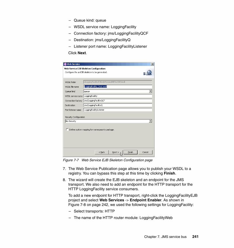
– Queue kind: queue
– WSDL service name: LoggingFacility
– Connection factory: jms/LoggingFacilityQCF
– Destination: jms/LoggingFacilityQ
– Listener port name: LoggingFacilityListener
Click Next.
Figure 7-7 Web Service EJB Skeleton Configuration page
7. The Web Service Publication page allows you to publish your WSDL to a registry. You can bypass this step at this time by clicking Finish.
8. The wizard will create the EJB skeleton and an endpoint for the JMS transport. We also need to add an endpoint for the HTTP transport for the HTTP LoggingFacility service consumers.
To add a new endpoint for HTTP transport, right-click the LoggingFacilityEJB project and select Web Services -> Endpoint Enabler. As shown in Figure 7-8 on page 242, we used the following settings for LoggingFacility:
– Select transports: HTTP
– The name of the HTTP router module: LoggingFacilityWeb
Chapter 7. JMS service bus 241

– The context root associated with the HTTP router module: LoggingFacility
Click OK.
Figure 7-8 Endpoint Enabler Configuration
When adding an endpoint for a Web service, the Endpoint Enabler tool makes the following changes:
– Adds the WebSphere endpoint servlet or message-driven bean to the router module:
• For an HTTP endpoint, it adds the following servlet to the web.xml deployment descriptor file in the selected HTTP router Web module (LoggingFacilityWeb in our case):
com.ibm.ws.webservices.engine.transport.http.WebServicesServlet and a mapping URL.
• For a JMS endpoint, it adds the following message-driven bean to the ejb-jar.xml deployment descriptor file in the selected JMS router EJB module (LoggingFacilityJMS in our case):
com.ibm.ws.webservices.engine.transport.jms.JMSListenerMDB
242 Patterns: Service-Oriented Architecture and Web Services

– Adds a link to the router module, to the ibm-webservices-bnd.xmi deployment descriptor file in the Web service module (LoggingFacilityEJB in our case), similar too:
• For an HTTP endpoint:
<routerModules transport="http" name="LoggingFacilityWeb.war"/>
• For a JMS endpoint:
<routerModules transport="jms" name="LoggingFacilityJMS.jar"/>
The service implementation code must now be written. The implementation code for the sample application is not discussed in detail. We modified the skeleton service implementation session bean that Studio has generated for us, org.ws_i.www.LoggingFacilitySoapBindingImpl.java, as shown in Example 7-1 in bold.
Example 7-1 Service implementation code extract for LoggingFacility service
/** * LoggingFacilitySoapBindingImpl.java * * This file was auto-generated from WSDL * by the IBM Web services WSDL2Java emitter. * 4 */
package org.ws_i.www;
import org.ws_i.www.Impl.DataStore;
public class LoggingFacilitySoapBindingImpl implements javax.ejb.SessionBean {private javax.ejb.SessionContext sessionContext = null;
private static DataStore impl = null;
public void ejbActivate() {}
public void ejbCreate() {impl = new DataStore();
}
public void ejbPassivate() {}
public void ejbRemove() {}
public javax.ejb.SessionContext getSessionContext() {
Chapter 7. JMS service bus 243

return sessionContext;}
public void setSessionContext(javax.ejb.SessionContext sc) {sessionContext = sc;
}
public void logEvent(org.ws_i.www.LogEventRequestType document)throws java.rmi.RemoteException {impl.addEntry(document);
}
public org.ws_i.www.GetEventsResponseType getEvents(org.ws_i.www.GetEventsRequestType document)throws java.rmi.RemoteException, org.ws_i.www.GetEventsFaultType {return impl.getEntry(document);
}
}
As you can see, we modified the generated skeleton to create an instance of the class containing the implementation code for the LoggingFacility service, org.ws_i.www.Impl.DataStore, and to invoke its methods as needed. You can find all the code in our version of the sample application.
Modifying the sample application to enable JMSRather than creating the JMS LoggingFacility service from scratch, as described here, you can enable the JMS endpoint in the sample application as follows:
1. Open LoggingFacility/META-INF/application.xml with the WebSphere Studio Source Editor and uncomment the JMS router module:
<!--module id="EjbModule_1079473348253"><ejb>LoggingFacilityJMS.jar</ejb>
</module-->
2. Open LoggingFacilityEJB/ejbModule/META-INF/ibm-webservices-bnd.xmi with the WebSphere Studio Source Editor and uncomment the link to the JMS router module:
<!--routerModules xmi:id="RouterModule_1079474059756" transport="jms" name="LoggingFacilityJMS.jar"/-->
Note: The DataStore should really be implemented using an entity bean, rather than using a static variable on the session bean. We only use the static to keep the implementation as simple as possible, so we can focus on service integration.
244 Patterns: Service-Oriented Architecture and Web Services

The sample application is available on the Web; see Appendix B, “Additional material” on page 333, for details.
7.3.2 Service consumer (client) development considerationsThe HTTP service consumer development considerations discussed in “Service consumer (client) development considerations” on page 200 also apply to JMS service consumers.
One point worth emphasizing here is configurability of our service-oriented architecture. The IBM WebSphere V5 Web services runtime allows us to easily reconfigure existing HTTP clients to use the new JMS transport. Let us look at the steps needed to switch Retailer, as a LoggingFacility service consumer, over to the new JMS transport.
Enabling an existing consumer to use the JMS transportTo reconfigure Retailer to use the new JMS transport:
1. In the Studio J2EE perspective, Project navigator view, navigate to RetailerWeb/WebContent/WEB-INF/wsdl.
2. Edit LoggingFacility_Impl.wsdl and change soap:address from:
<wsdlsoap:address location="http://appsrv1l.itso.ral.ibm.com:9080/LoggingFacility/services/LoggingFacility"/>
To:
<wsdlsoap:address location="jms:/queue?destination=jms/LoggingFacilityQ&connectionFactory=jms/LoggingFacilityQCF&targetService=LoggingFacility"/>
Save your changes.
3. Edit LoggingFacility.wsdl and change soap:binding from:
<soap:binding transport="http://schemas.xmlsoap.org/soap/http" style="document"/>
To:
<soap:binding transport="http://schemas.xmlsoap.org/soap/jms" style="document"/>
Save your changes.
Notice the warning that appears in the Studio task list: WS-I: Transport attribute of the soap:binding does not contain http://schemas.xmlsoap.org/soap/http. This WS-I compliance warning appears because the JMS transport is not part of the WS-I Basic Profile 1.0.
Chapter 7. JMS service bus 245

After these changes to the WSDL file, it is just a matter of configuring the JMS resources needed and redeploying the application. See “Service consumer (client) deployment considerations” on page 247 for details.
Enabling a new consumer to use the JMS transportThe WebSphere Studio Web Service Client wizard can be used to JMS Web service enable new LoggingFacility service consumers.
You can use the same procedure for JMS, as described for HTTP with Warehouse as a consumer of Manufacturer in 6.3.4, “Service consumer (client) development considerations” on page 200.
In this case, use the LoggingFacility_Impl.wsdl file we created in “Describing the service” on page 234, rather than the original LoggingFacility_Impl.wsdl.
7.4 Runtime guidelinesOnce the services or service consumers are developed, they need to be deployed to a runtime environment. For this project, we used IBM WebSphere Application Server V5.1, which provides runtime support for JMS Web services.
7.4.1 Service deployment considerationsTo deploy the new LoggingFacility service, we performed the following steps:
1. In WebSphere Studio, export the LoggingFacility project as an EAR file.
2. Copy the exported EAR to the application server that you want to deploy to.
We recommend that you copy the EAR file to the <WAS_HOME>/installableApps folder on the application server.
3. To configure the JMS queue connection factory, queue, and listener port needed for the LoggingFacility JMS transport:
a. We used IBM WebSphere MQ as the JMS provider, and created the following queue manager and queue on appsrv1l:
• SCM.LOG.QM queue manager
• LoggingFacilityQ queue
b. In the WebSphere Administrative Console, create the queue connection factory by navigating to Resources -> WebSphere MQ JMS Provider -> WebSphere MQ Queue Connection Factories. In the WebSphere MQ Queue Connection Factories form, click New then:
i. Set Name to LoggingFacilityQCF.
246 Patterns: Service-Oriented Architecture and Web Services

ii. Set JNDI Name to jms/LoggingFacilityQCF.iii. Set Queue Manager to SCM.LOG.QM.
Click OK to accept the defaults for the remaining fields.
c. Create the queue by navigating to Resources -> WebSphere MQ JMS Provider -> WebSphere MQ Queue Destinations. In the WebSphere MQ Queue Destinations form, click New, then:
i. Set Name to LoggingFacilityQ.ii. Set JNDI Name to jms/LoggingFacilityQ.iii. Set Base Queue Name to LoggingFacilityQ.
Click OK to accept the defaults for the remaining fields.
d. Create the listener port(s) by navigating to Servers -> Application Servers -> server1 -> Message Listener Service -> Listener Ports. In the Listener Ports form, click New, then:
i. Set Name to LoggingFacilityListener.ii. Set Connection factory JNDI name to jms/LoggingFacilityQCF.iii. Set Destination JNDI name to jms/LoggingFacilityQ.
Click OK to accept the defaults for the remaining fields.
e. Save your changes and restart the server.
4. Install the LoggingFacility service on a WebSphere Application Server instance using the same procedure, as described for Manufacturer.ear in “Deploying a service” on page 215.
7.4.2 Service consumer (client) deployment considerationsThe main difference when deploying the service consumer is in the configuration of the JMS provider, IBM WebSphere MQ in our case. To deploy the new Retailer, a JMS consumer of the LoggingFacility service, we performed the following steps:
1. In WebSphere Studio, export the Retailer project as an EAR file.
2. Copy the exported EAR to the application server that you want to deploy to.
We recommend that you copy the EAR file to the <WAS_HOME>/installableApps folder on the application server.
3. Configure the JMS queue connection factory, queue, and listener port needed for accessing the LoggingFacility JMS transport.
We used IBM WebSphere MQ as the JMS provider, and used the MQ client to access the remote queue manager and queue on appsrv1l. Consider using a local, clustered queue manager to take advantage of MQ workload and failover management.
Chapter 7. JMS service bus 247
To configure the JMS resources needed:
a. In the WebSphere Administrative Console, create the queue connection factory by navigating to Resources -> WebSphere MQ JMS Provider -> WebSphere MQ Queue Connection Factories. In the WebSphere MQ Queue Connection Factories form, click New, then:
i. Set Name to LoggingFacilityQCF.ii. Set JNDI Name to jms/LoggingFacilityQCF.iii. Set Queue Manager to SCM.LOG.QM.iv. Set Host to appsrv1l.itso.ral.ibm.com®.v. Set Port to 1414.vi. Set Transport Type to CLIENT.
Click OK to accept the defaults for the remaining fields.
b. Create the queue by navigating to Resources -> WebSphere MQ JMS Provider -> WebSphere MQ Queue Destinations. In the WebSphere MQ Queue Destinations form, click New, then:
i. Set Name to LoggingFacilityQ.ii. Set JNDI Name to jms/LoggingFacilityQ.iii. Set Base Queue Name to LoggingFacilityQ.
Click OK to accept the defaults for the remaining fields.
c. Save your changes and restart the server.
4. Install the Retailer application on a WebSphere Application Server instance. You can use the same procedure as described for Manufacturer.ear in “Deploying a service” on page 215.
Be sure to select the Deploy WebServices option if you did not regenerate the Web service client in Studio.
7.4.3 Testing considerationsIn addition to the considerations discussed in 6.3.5, “Testing considerations” on page 210, the WebSphere MQ Explorer (shown in Figure 7-9 on page 249) can be helpful for basic troubleshooting of JMS transport issues.
248 Patterns: Service-Oriented Architecture and Web Services

Figure 7-9 WebSphere MQ Explorer
You can use the Message Browser to look at messages arriving on the destination queue for the JMS transport. With the LoggingFacility stopped, we could view a logEventRequest message placed on the queue by Retailer, as shown Figure 7-10.
Figure 7-10 Properties for Message logEventRequest
Chapter 7. JMS service bus 249

250 Patterns: Service-Oriented Architecture and Web Services

Chapter 8. Service directory
In this chapter we discuss the use of an e-business service directory in the context of the sample application introduced in Chapter 6, “HTTP service bus” on page 159. A service directory is generally perceived as a key enabler of dynamic e-business. It is important to understand how the current technologies and standards help us achieve those goals.
We examine use of the Direct Connection Rules Repository node to model a service directory, as described in “Basic Direct Connection runtime pattern” on page 63. Introducing this node allows a service consumer to discover services using a service directory.
In this chapter, the following topics are discussed:
� The sample business scenario that our solution needs to address
� Design guidelines describing the guiding principles we used when modifying the sample application
� Development guidelines showing how we implemented the sample application changes
� Runtime guidelines discussing the considerations for deploying the service directory
� Best practices summarizing the things you should consider when deploying a service directory
8
© Copyright IBM Corp. 2004. All rights reserved. 251

8.1 Business scenarioThe sample application used in this chapter is the same simplified WS-I Supply Chain Management (SCM) sample used in the previous chapters. We introduce a non-functional requirement that involves a lookup in a service directory.
In this scenario, the requirement is a more flexible and efficient way of locating services in the organization. The business wants to reduce the IT management costs associated with changing the location of service providers, in both test and production environments. The IT department has reviewed the technology options available, and decided that a UDDI registry should be used to look up service provider endpoint URLs, starting with a pilot for retailer access of the warehouse service. The change to the business scenario is shown in Figure 8-1.
Figure 8-1 High-level business context with service discovery
The architecture of the WS-I SCM sample application includes the potential usage of entries in the UDDI Business Registry (UBR), a public UDDI registry offered by several companies, including IBM, Microsoft, and SAP.
The SCM Web services are published as tModels in the UBR. The tModelKeys are listed in “Advertisement of tModels” of the WS-I Supply Chain Management Sample Application Architecture document. Figure 8-2 on page 253 shows the UBR entry for the Warehouse service tModel from the IBM UBR at:
https://uddi.ibm.com/ubr/registry.html
Browser
ConsumerRetailer
Inte
rnet
Inte
rnet
Organization boundary
Warehouse
Logging Facility
Manufacturer
Add service discovery
252 Patterns: Service-Oriented Architecture and Web Services

Figure 8-2 Warehouse service tModel entry in the UDDI Business Registry
The purpose of publishing the WS-I SCM services in the UBR is to allow the discovery of the service interface definitions (in WSDL files). This information is necessary to build a Web service client. However, neither the name of the Business Entity providing the service nor the URL for accessing the implementation of the service (the server where the service actually runs) are given. Vendors participating in the WS-I sample scenario need to provide that information in the UBR once they have built their services and made them available on the Web.
Chapter 8. Service directory 253

Vendors build their implementations of the WS-I sample services in accordance with the WSDL descriptions available from pointers in the UBR. As multiple services are built using the same descriptions, they should not only be interoperable but interchangeable as well. For example, the Warehouse implementation of one vendor should give the same results as the Warehouse implementation of another vendor. The sample application can potentially use different vendors of the same service, by making a simple runtime configuration change in the service consumer (Retailer in the case of the Warehouse service).
It is our understanding that the SCM scenario does not intend to provide dynamic discovery of service interfaces at run time; rather, it aims to allow the use of different providers of the same service.
Our aim in this chapter is slightly different. We focus on another facet of service discovery. Currently, most Web service implementations are not using dynamic discovery of services (that includes discovery of interface and implementation definitions) at runtime. But static discovery is not enough to cope with important quality of service and infrastructure issues.
One of the expected benefits of an SOA architecture is the ability to better cope with changes. Loosely coupled services should allow more flexibility than tightly coupled applications.
A basic issue that comes to mind concerning flexibility is that services may not remain at a given physical location over time. IT production departments may need to move them from one server to another. An obvious need is the promotion of code from one environment to another, such as from test to production. The service used for test or integration purposes cannot be at the same location as the production service. Moreover, one could think of locating several identical services in different places to provide high availability (via failover) and potentially some level of load balancing.
In this chapter, we essentially tackle how a service consumer can change from a service provider in one location to a provider in another location, with as few changes as possible to the application code or the deployment descriptors.
8.2 Design guidelinesIn our sample application, the location of a service is found by reading the WSDL implementation document of the service at build or deployment time.
254 Patterns: Service-Oriented Architecture and Web Services

To relocate a service, we need to take several actions with the service provider and the service consumer:
� Service provider side:
– Implement the service at another location on another server.
– Make the modified WSDL implementation document available to the consumers of the service.
� Service consumer side:
– Get the new WSDL implementation file.
– Regenerate the Web service client deployment code from the new WSDL.
– Redeploy the service consumer (client) on its server.
8.2.1 Design overviewWe want to extend the application by adding the capability to use a service in a different location without touching the service consumer and the WSDL document used. To do this, we intend to:
� Implement a private UDDI registry where the service location will be published and changed.
� Modify the service consumer to look up the endpoint address of the invoked service. In this case, we will modify the Retailer as a consumer of the Warehouse service.
� Create a new helper class that will query the UDDI registry where the service location is published and return the current endpoint URL for the service.
Figure 8-3 on page 256 shows the high-level solution overview for the WS-I SCM sample application we developed in Chapter 4, “Service-oriented architecture approach” on page 79. In this section we add a service directory Product mapping for the Runtime pattern highlighted in Figure 8-3 on page 256.
Chapter 8. Service directory 255
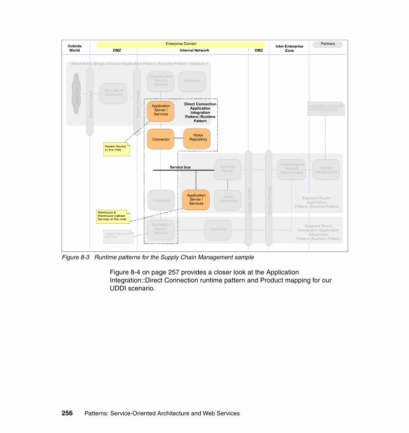
Figure 8-3 Runtime patterns for the Supply Chain Management sample
Figure 8-4 on page 257 provides a closer look at the Application Integration::Direct Connection runtime pattern and Product mapping for our UDDI scenario.
Web Server Redirector
Dom
ain
Fire
wal
l
Prot
ocol
Fire
wal
l
Inte
rnet
Dom
ain
Fire
wal
l
Enterprise Domain Partners
DMZ DMZInter-Enterprise
ZoneInternal NetworkOutside World
Stand-Alone Single Channel Application Pattern::Runtime Pattern: Variation 1
Direct Connection Application Integration
Pattern::Runtime Pattern
Retailer Service on this node
Manufacturer Service on Partner Infrastructure
Exposed Router Application
Pattern::Runtime Pattern
Connector
Prot
ocol
Fire
wal
l
Exposed Direct Connection Application
Integration Pattern::Runtime Pattern
Exposed Router
Rules Repository
Application Server / Services
Directory and Security Services
ConnectorApplication
Server / Services
Database
Application Server / Services
Rules RepositoryConnector
Partner Infrastructure
InterEnterprise Network
Infrastructure
Warehouse & Warehouse Callback Services on this node
Logging Service on this node
Service bus
256 Patterns: Service-Oriented Architecture and Web Services

Figure 8-4 Product mapping for Application Integration::Direct Connection pattern
Figure 8-4 shows that UDDI Registry provided with IBM WebSphere Application Server Network Deployment V5.0.2.4 performs the rules repository role, allowing service consumers to look up the endpoint URL of the required service provider. The Connector in Figure 8-4 can be decomposed into a set of coupling adapter connectors, similar to Figure 6-3 on page 163, allowing the service consumer to first invoke the lookup service provided by the UDDI services, then invoke the target service provider.
We used both Windows and AIX systems in the service directory deployment. Figure 8-4 shows an example where a service consumer (retailer) interacts with a service provider (warehouse) using the service directory.
8.2.2 Service design considerationsFigure 8-5 on page 258 shows the interaction between the service consumer, directory and provider for our service directory scenario.
Internal network
Connector
RulesRepository
App Server/Services
App Server/Services
<Service Provider><Service Consumer>
<Service Directory>
AIX 5.1 ML4IBM WebSphere Application Server V5.0.2.4 Network Deployment - UDDI RegistryIBM DB2 UDB ESE V8.1
Windows 2000 + SP4IBM WebSphere Application Server V5.1
Windows 2000 + SP4IBM WebSphere Application Server V5.1
Chapter 8. Service directory 257

Figure 8-5 Sequence diagram for the UDDI scenario
Mapping WSDL information to UDDI entriesIn “UDDI” on page 141 we provide an introduction to the relationship between the information contained in WSDL documents and their corresponding entries in a UDDI registry.
A good understanding of these mappings is necessary to correctly query information from the UDDI registry.
8.3 Development guidelinesIn this section we look at some UDDI development tools and describe the development environment steps needed to build and test the application with its new service discovery capabilities.
8.3.1 UDDI development tools and APIsDevelopment tools and APIs that you can use when implementing a UDDI service directory include:
� WebSphere Studio Application Developer
� UDDI4J and UDDI4JV2
� UDDI Extensions from IBM alphaWorks
/ Provider : Warehouse/ Directory : UDDI/ Consumer : Retailer
1 : \RequestEndPointURL\
Response
2 : \ShipGoodsRequest\
ShipGoodsResponse
258 Patterns: Service-Oriented Architecture and Web Services

WebSphere Studio Application DeveloperWebSphere Studio V5.1 provides a number of tools to enable publishing and discovery of Web services using UDDI, including:
� Web Services Client wizard for creating a Java client to a deployed Web service and for testing the Web service
� Unit Test UDDI wizard for installing, configuring, and removing a private UDDI registry
� Web Services Explorer for discovering and publishing your Web service descriptions
These tools provide facilities to browse the UDDI registries or WSIL documents to locate existing Web services for integration. Web services can be published to a UDDI V2 Business Registry, advertising your Web services so that other businesses and clients can access them. These tools support the following specifications:
� Universal Description, Discovery, and Integration 2.0
� Web Services Inspection Language (WSIL) 1.0
UDDI4J and UDDI4JV2The UDDI standard describes a set of XML messages that can be exchanged between a service consumer (client program) and a UDDI registry.
UDDI4J is a client Java API used to interact with a UDDI registry. This class library generates and parses messages sent to and received from a UDDI server. It provides two mains sets of APIs:
� Publish APIs, which are used by the provider to manage its entries in the directory. It contains Query, Save, Delete and Authorization methods.
� Inquiry APIs, which are used by the requester and the provider to retrieve service information. It contains Find and Retrieve methods.
UDDI4J follows the evolution of the UDDI standards. UDDI4J is the API used to communicate with UDDI V1 directories, while UDDI4J V2 is the API used to communicate with UDDI V2 directories. As UDDI registries are accessed via Web service protocols, a SOAP transport is required to use UDDI4J V1 or V2.
The classes of UDDI4J have the prefix com.ibm.uddi. The classes of UDDI4JV2 have the prefix org.uddi4j. The UDDI directory provided with IBM WebSphere Application Server Network Deployment V5.0 is a UDDI V2 directory, so client applications need to use the UDDI4JV2 APIs to find information about a service.
For more information on UDDI4J see:
http://www.ibm.com/developerworks/oss/uddi4j/
Chapter 8. Service directory 259

UDDI Extensions from IBM alphaWorksThe IBM alphaWorks UDDI Registry Extensions provide advanced UDDI search capabilities. They enable the formation of complex queries comprising search criteria from two standard UDDI “find” APIs, find_business and find_service, in a single query. That is, the find_business API is extended with an embedded find_service API, and find_service with an embedded find_business API.
The equivalent queries are complex and error-prone with the current UDDI search technology. The client search requester must perform two steps:
1. Issue two queries: A find_business query and a find_service query.
2. Process the two sets of results returned by the queries and find the appropriate intersection of the results.
The UDDI Registry Extensions reduce client programming complexities and make UDDI easier to use. They also reduce network bandwidth usage and improve performance.
For more information on the UDDI Registry Extensions see:
http://www.alphaworks.ibm.com/tech/uddiregextensions
8.3.2 Service development considerationsTo enable the discovery of service location at runtime, we first to need to establish a UDDI registry in our development/test environment and publish the service to it.
Deploying the WebSphere Studio Unit Test UDDI registryWe choose to use the Unit Test UDDI registry available in WebSphere Studio Application Developer V5.1.1 in our development and unit test environment.
This registry is very convenient and simple to install. It can use either a DB2 database, or the lightweight Cloudscape™ database provided with Studio.
To deploy the WebSphere Studio Unit Test UDDI registry:
1. Click File -> New -> Other... from the Studio main menu.
2. Select Web Services, Unit Test UDDI in the New window, then click Next.
3. In the Unit Test UDDI Registry Configuration window, we selected Private UDDI Registry For WAS v5.1 with Cloudscape for the unit tests, as shown in Figure 8-6 on page 261. Click Next.
260 Patterns: Service-Oriented Architecture and Web Services

Figure 8-6 Unit Test UDDI Registry Configuration in WebSphere Studio
4. In the Unit Test UDDI Registry with Cloudscape Configuration window, you need to take care to select Use an existing test server. If not, a new one will be created. As shown in Figure 8-6, click Finish to create the Unit Test Registry.
Chapter 8. Service directory 261

Figure 8-7 Unit Test UDDI Registry with Cloudscape Configuration
The wizard adds the following projects to the Studio workspace:
� UDDI-EAR� UDDI-EJB� UDDI-SOAP
You can then use the Web Services Explorer to publish a service in the Unit Test UDDI Registry. We published the Warehouse service to the Unit Test UDDI Registry as follows:
1. Start the Web Services Explorer by selecting Run -> Launch the Web Services Explorer from the Studio main menu. If needed, open the Unit Test UDDI Registry using Inquiry URL:
http://localhost:9080/uddisoap/inquiryapi
2. Click the UDDI Page icon on the Web Services Explorer toolbar to work with UDDI registries.
3. Click the Publish icon on the Actions toolbar, as shown in Figure 8-8 on page 263.
262 Patterns: Service-Oriented Architecture and Web Services

Figure 8-8 Web Services Explorer
4. To publish the service interface, select Service Interface and complete the required details in the Publish form, as shown in Figure 8-9.
Figure 8-9 Publish Service Interface
5. To publish the business, select Business and complete the required details in the Publish form, as shown in Figure 8-10 on page 264.
Chapter 8. Service directory 263

Figure 8-10 Publish Business
6. Scroll down to the bottom of the Business Details form and click Publish Service to add a service to the business.
7. To publish the service, select Service and complete the required details in the Publish Service form, as shown in Figure 8-11.
Figure 8-11 Publish Service
Using the Web Services Explorer, we have published the interface WSDL as a tModel. Then we published the implementation WSDL. A pointer to this implementation WSDL goes into the overviewURL element of the tModelInstanceDetails of the bindingTemplate. As part of this publishing process, the accessPoint element of the bindingTemplate is updated with the endpoint address in the implementation WSDL.
264 Patterns: Service-Oriented Architecture and Web Services

As described in 8.4.1, “Service deployment considerations” on page 269, the process is slightly different in the runtime environment. You can set the accessPoint element directly from the UDDI Registry user console with IBM WebSphere Application Server Network Deployment V5.0.
8.3.3 Service consumer (client) development considerationsAs discussed in “Invoking the service” on page 209, there are three main design alternatives for invoking a service using JAX-RPC. They are stub based, dynamic invocation interface, and dynamic proxy.
The SCM application uses static stubs. A static stub is a Java class that is statically bound to the Service Endpoint Interface (SEI), WSDL port, and port component. It is also tied to a specific protocol binding and transport. A stub class defines all the methods that an SEI defines. Therefore a client can invoke a Web service directly via the stub class. However, each time the Web service definition is modified (interface or implementation) the stub class must be regenerated.
We need to modify the Retailer application to locate the endpoint URL of the Warehouse service in a private UDDI registry. In the development environment, the service provider and consumer will usually reside on the same server. There is often no interest at this stage in relocating the service to different servers. So we chose to modify the client code to allow use of both static and dynamic service discovery, depending on the setting of the following environment variables in the RetailerWeb application:
� uddiEnabled (set to true or false)� uddiInquiryURL� uddiPublishURL� uddiWarehouseService� uddiWarehouseBusiness
Example 8-1 shows an extract of the code we added the Retailer application to perform the UDDI lookup.
Example 8-1 Extract of the modified Retailer code
...WarehouseService service = null;WarehouseShipmentsPortType port = null;
try {Context ctx = new InitialContext();service = (WarehouseService)
ctx.lookup("java:comp/env/service/WarehouseService");if (useUDDI == true) {
Chapter 8. Service directory 265

// Use the UDDIHelper class to look up the end point URLif (whUDDIHelper == null) {
whUDDIHelper = new UDDILookupHelper(whUDDIInquiryURL, whUDDIPublishURL,whUDDIService, whUDDIBusiness);
}port = service.getWarehouse(
new java.net.URL(whUDDIHelper.getAccessPoint()));} else {
// Use the end point URL from the wsdl-file entry in// webservicesclient.xmlport = service.getWarehouse();
}} catch(Exception ex) {
if (useUDDI == true) {whUDDIHelper = null; // failed so try a new UDDIHelper next time
...}
}...
The UDDILookupHelper class contains the logic that queries the UDDI registry. It is imported by the Retailer Java code. Example 8-2 provides an extract of the logic used to search the UDDI registry.
Example 8-2 Extract of the UDDILookupHelper class
...public String getAccessPoint() throws
java.net.MalformedURLException,org.uddi4j.UDDIException,org.uddi4j.transport.TransportException{
if (accessPoint == null) {java.net.URL inquiryURL = new java.net.URL(inquiryURLStr);java.net.URL publishURL = new java.net.URL(publishURLStr);
UDDIProxy uddiProxy = new UDDIProxy(inquiryURL, publishURL);
TModelInfo tModelInfo = uddiProxy.find_tModel(serviceName, null, null, null, 1).getTModelInfos().get(0);
String serviceInterfaceKey = tModelInfo.getTModelKey();System.out.println("found key : "+serviceInterfaceKey);
Vector nameVector = new Vector();nameVector.add(new org.uddi4j.datatype.Name(new String(businessName)));BusinessInfo businessInfo = uddiProxy.find_business(
nameVector, null, null, null, null, null, 1).getBusinessInfos().get(0);
266 Patterns: Service-Oriented Architecture and Web Services

String businessKey = businessInfo.getBusinessKey();System.out.println("found business key : "+businessKey);
Vector serviceInfoVector = uddiProxy.find_service(businessKey, null, null, null, null, 10
).getServiceInfos().getServiceInfoVector();Enumeration serviceInfoEnum = serviceInfoVector.elements();BindingTemplate bindingTemplate = null;while (serviceInfoEnum.hasMoreElements()) {
ServiceInfo serviceInfo = (ServiceInfo)serviceInfoEnum.nextElement();String serviceKey = serviceInfo.getServiceKey();Vector businessServiceVector = uddiProxy.get_serviceDetail(
serviceKey).getBusinessServiceVector();BusinessService businessService =
(BusinessService)businessServiceVector.elementAt(0);Vector bindingsVector =
businessService.getBindingTemplates().getBindingTemplateVector();for (int i=0;i<bindingsVector.size();i++) {
bindingTemplate = (BindingTemplate)bindingsVector.elementAt(i);if (bindingTemplate.getServiceKey().equals(serviceInterfaceKey))
break;}
}accessPoint = bindingTemplate.getAccessPoint().getText();System.out.println("found access point with URL "+accessPoint);
}return accessPoint;
}...
Walking through Example 8-2 on page 266, we first instantiate a UDDI proxy with the appropriate URLs. We then look for the service interface, which was stored as a tModel with a particular name. Note that we are not using any of the advanced features of UDDI, such as the CategoryBag. We simply search for the name, because we know what it is. This code would be more complex if we were to search for a tModel using a different set of search criteria.
Then we find the service entry that references this tModel. Unfortunately, there is not one query API that allows us to do this; we have to query all services for the business and check each one for a match. We get all of the services that are defined for the business. We retrieve all of the binding templates defined for each service. Each binding template contains a key field pointing to its respective tModel. Once we find the binding template that points to the service interface we retrieved earlier, we can stop looking.
The actual endpoint URL of the service is stored in the access point field of the binding template.
Chapter 8. Service directory 267

See the following classes for the full code listings:
� org.ws_i.www.Impl.RetailerLogic in the RetailerWeb project� com.ibm.itso.uddi.UDDILookupHelper in the UDDIUtility project
These classes are included in our version of the sample application available on the Web; see Appendix B, “Additional material” on page 333, for details.
8.3.4 Testing considerationsWe used the TCP/IP Monitor tool provided with WebSphere Studio to validate the data exchanged between the various servers.
TCP/IP Monitor allows messages to be traced by redirecting messages from one TCP/IP port to another, displaying the contents as they go. The application server normally listens on port 9080. To trace messages sent to the application server, TCP/IP Monitor can be configured, for example, to listen on port 80 and redirect messages to 9080. The client is modified to use port 80 to access the server.
To use TCP/IP Monitor, create a new Server and Configuration and select Other -> TCP/IP Monitor Server for the server type.
Figure 8-12 shows our UDDI inquiry captured using TCP/IP Monitor.
Figure 8-12 TCP/IP Monitor
268 Patterns: Service-Oriented Architecture and Web Services

8.4 Runtime guidelinesAfter implementing and testing the application changes to add our UDDI registry, they need to be deployed to a runtime environment. Our services and service consumers remain on IBM WebSphere Application Server V5.1, but we add IBM WebSphere Application Server Network Deployment V5.0.2.4, which includes a UDDI Registry.
8.4.1 Service deployment considerationsThe Retailer now has two options for finding the location of the Warehouse service:
� Using the static stub generated at development or deployment time, from the deployment descriptors and WSDL packaged with the application.
� Using a lookup to a private UDDI registry. For this option, we need to deploy and populate a private UDDI registry. We also need to redeploy the updated Retailer application, which is a Warehouse service consumer.
Deploying the UDDI RegistryThe UDDI Registry is essentially a J2EE application installed in the WebSphere Application Server runtime. When deploying the UDDI Registry, there are two main choices to make for the installation:
� Install on a single application server or on a server in a deployment manager cell.
We used a single server application server because our scenario did not require the full IBM WebSphere Application Server Network Deployment V5.0.2.4 installation.
� The database for persistence.
We used IBM DB2 UDB V8.1 to simulate a production-oriented environment. The lightweight Cloudscape database is an interesting choice for preliminary tests only.
Details for completing the installation can be found in the WebSphere Information Center article, Installing the UDDI Registry into a single appserver at:
http://www.ibm.com/software/webservers/appserv/infocenter.html
Populating the UDDI RegistryFor this scenario, we need to populate the UDDI Registry with a Business Entity named “Warehouse Business”, a service named “Warehouse Service”, and a
Chapter 8. Service directory 269

tModel named “Warehouse Service”. We considered two ways of populating the registry:
� Using a Java program using the UDDI4J publish API
� Using the administration interface provided by the registry
Rather than custom building a program, we used the following steps to publish the Warehouse service using the WebSphere UDDI Registry user console.
For this example, we use the Manufacturer service. It imports five WSDL files and XML schema files. To provide access to the Manufacturer service description:
1. Create a new folder called wsdl under the <WAS_HOME>/installedApps/<node_name>/UDDIRegistry.ear/gui.war folder on your WebSphere UDDI Registry node.
2. Locate the following files in the WarehouseWeb/WebContent/WEB-INF/wsdl folder under your WebSphere Studio workspace for the supply chain management sample:
– Warehouse_Impl.wsdl– Warehouse.wsdl– Warehouse.xsd– Configuration.wsdl– Configuration.xsd
3. Copy these files to the new wsdl folder on your UDDI registry node. In our case, the Warehouse_Impl.wsdl file will now be accessible in the gateway administrative console Web module with the following URL:
http://appsrv1a.itso.ral.ibm.com/uddigui/wsdl/Warehouse_Impl.wsdl
4. Edit the WSDL to make sure any imports will be accessible from client applications. For example, our Warehouse_Impl.wsdl contains two relative imports that need to be updated. We changed:
– location="Warehouse.wsdl" to "http://appsrv1a.itso.ral.ibm.com/uddigui/wsdl/Warehouse.wsdl"
– location="Configuration.wsdl" to "http://appsrv1a.itso.ral.ibm.com/uddigui/wsdl/Configuration.wsdl"
5. Save your changes.
Note: We deployed our service WSDL and XML schema files to the UDDI user console Web module for simplicity only. In a production environment, it would make more sense to deploy these files to an appropriate Web server. This topic is discussed further in 8.5, “Best practices” on page 275.
270 Patterns: Service-Oriented Architecture and Web Services

6. Open the WebSphere UDDI Registry user console in a Web browser using the following URL:
http://appsrv1a.itso.ral.ibm.com/uddigui/
7. To add a tModel for the Warehouse service:
a. Click Add a technical model from the Publish tab in the navigation frame on the left.
b. In the Publish Technical Model form:
• Under Technical Model Name, set Name to Warehouse Service.
• Under Descriptions, set New description to Description of Warehouse Service Interface and click Add.
• Under Overview URL, set URL to http://appsrv1a.itso.ral.ibm.com/uddigui/wsdl/Warehouse.wsdl.
• Under Locator, click Show category tree. In the category tree, select udditype -> tModel -> specification -> wsdlSpec, as shown in Figure 8-13, then click Add.
Click Publish Technical Model.
Figure 8-13 Selecting wsdlSpec for the tModel
8. To add a business for the Warehouse service:
a. Click Add a business from the Publish tab in the navigation frame, as shown in Figure 8-14 on page 272.
b. In the Publish Business form, under Business Name:
i. Set New name to Warehouse Business and click Add.ii. Click Publish Business.
Chapter 8. Service directory 271

Figure 8-14 WebSphere UDDI Registry user console
9. To add a service to the new business:
a. Click Show owned entities from the Publish tab in the navigation frame.
b. Locate the Warehouse Business in the list of registered businesses and click Add service.
c. In the Publish Service form:
i. Under Service Name, set New name to Warehouse Service and click Add.
ii. Under Access Points, set URL type to http and Address to appsrv1w.itso.ral.ibm.com:9080/Warehouse/services/Warehouse and click Add.
iii. Under Technical Models, click Add..., then find and select the Warehouse Service Technical Model.
iv. Click Publish Service.
272 Patterns: Service-Oriented Architecture and Web Services
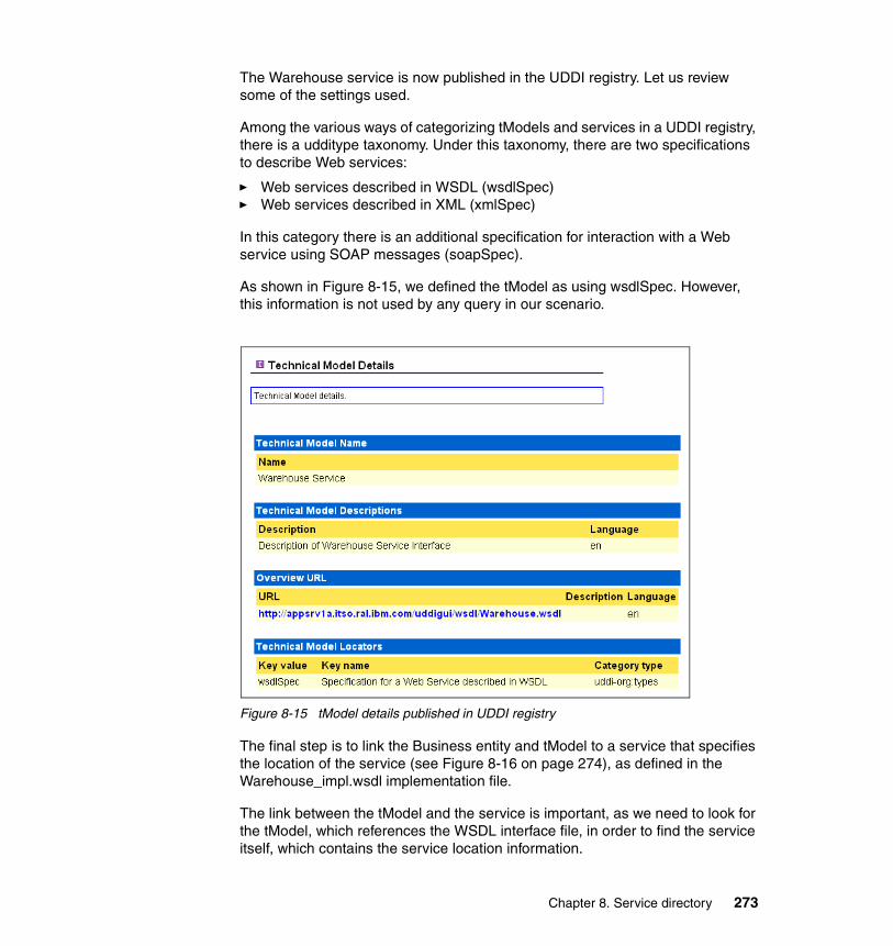
The Warehouse service is now published in the UDDI registry. Let us review some of the settings used.
Among the various ways of categorizing tModels and services in a UDDI registry, there is a udditype taxonomy. Under this taxonomy, there are two specifications to describe Web services:
� Web services described in WSDL (wsdlSpec)� Web services described in XML (xmlSpec)
In this category there is an additional specification for interaction with a Web service using SOAP messages (soapSpec).
As shown in Figure 8-15, we defined the tModel as using wsdlSpec. However, this information is not used by any query in our scenario.
Figure 8-15 tModel details published in UDDI registry
The final step is to link the Business entity and tModel to a service that specifies the location of the service (see Figure 8-16 on page 274), as defined in the Warehouse_impl.wsdl implementation file.
The link between the tModel and the service is important, as we need to look for the tModel, which references the WSDL interface file, in order to find the service itself, which contains the service location information.
Chapter 8. Service directory 273

Figure 8-16 Service details published in UDDI registry
The tModelKey that we have received is imposed by the system. There is no way to use a predefined key in UDDI V2 specification. The idea is to prevent duplicate keys causing problems in the UBR, the public UDDI service. However, as we are using a private UDDI registry, it makes sense that the key can be locally managed if desired. The UDDI V3 specification offers a solution to this issue. Locally managed keys allow for easier exchange of information between private UDDI test registries and private UDDI production registries.
Redeploying the service consumerAs discussed in 8.3.3, “Service consumer (client) development considerations” on page 265, we make some changes to the Retailer application to locate the endpoint URL of the Warehouse service using UDDI.
To enable the UDDI lookup, first set the uddiEnabled environment variable in the RetailerWeb module to true using the WebSphere Studio Deployment Descriptor Editor, as shown in Figure 8-17 on page 275.
274 Patterns: Service-Oriented Architecture and Web Services

Figure 8-17 Retailer Environment Variable for UDDI integration
After setting the environment variable(s), export Retailer.ear from Studio for deployment to the WebSphere Application Server runtime. See 6.4.1, “Service deployment considerations” on page 214 for an example of exporting and deploying an EAR file.
8.5 Best practicesIn this section we look at service discovery best practices in a J2EE environment like WebSphere Application Server, and how such practices can benefit SOA.
8.5.1 Using UDDI and WSDL togetherUDDI entries can be configured manually, as we did in “Populating the UDDI Registry” on page 269, or programmatically. Not all fields are particularly relevant to Web services, but still need to be consistent with the complete WSDL document describing a service. The UDDI standard has been built to offer more functions than those strictly needed for Web services. The UDDI information can contain metadata about the provider as well as the service.
Tools like WebSphere Studio Application Developer make it easier to create the UDDI description from a WSDL file or from Java source in the development environment. When you publish a service, however, you need to decide where to store the WSDL files since the UDDI registry only contains pointers to the WSDL.
You can leave the WSDL files in the Web project associated with a service. Alternatively, you may prefer to make the WSDL files available via HTTP, as we did in “Populating the UDDI Registry” on page 269, or in a specific directory on the UDDI registry file system.
Chapter 8. Service directory 275

We also recommend the following documents from the OASIS UDDI Specification TC:
� Using WSDL in a UDDI Registry, Version 1.08 at:
http://www.oasis-open.org/committees/uddi-spec/doc/bp/uddi-spec-tc-bp-using-wsdl-v108-20021110.htm
� Using WSDL in a UDDI Registry, Version 2.0 at:
http://www.oasis-open.org/committees/uddi-spec/doc/tn/uddi-spec-tc-tn-wsdl-v200-20030627.htm
8.5.2 WebSphere Studio and WebSphere UDDI registry differencesThe Web Services Explorer user interface for the WebSphere Studio UDDI registry works differently from UDDI Registry user console for IBM WebSphere Application Server Network Deployment V5.0. This can create some confusion about how to set the service endpoint URL.
With the Web Services Explorer and Studio, the address that is stored and shown is indeed the URL of the implementation WSDL. However, this is not the access point that is stored in the accessPoint variable in UDDI. The Web Services Explorer does not provide access to the accessPoint. It is copied from the implementation WSDL file when you publish. You can only change it later by publishing a new service.
In the runtime environment, we do not actually need the WSDL files, as our Web service consumer (client) uses a static stub. The client only needs to look up the endpoint address at runtime.
8.5.3 Dynamic or static discovery during the Web service life cycleAs with any programming artifact, Web services have a life cycle composed of a number of phases such as:
� Development phase
� Deployment phase
� Runtime phase
We have seen previously that a Web service is essentially defined by a service interface and a service implementation. The discovery of the service interface and of the service location can either be static or dynamic. The benefits of each kind of discovery vary during the different phases of the life cycle of the Web service and its clients.
276 Patterns: Service-Oriented Architecture and Web Services

Figure 8-18 provides a summary of dynamic discovery of either interface or location during the Web service life cycle.
Figure 8-18 Static and dynamic discovery during the Web service life cycle
We can use this framework to further explore potential benefits of static and dynamic discovery during the Web service life cycle:
� Quadrant 1
Static discovery of interfaces and location is the basic situation.
� Quadrant 2
At runtime, we think the service interfaces are known by the Web service consumers most of the time. They are modified rarely, if ever. So, the most pressing need is to cope with service location flexibility without modifying the consumers. That is the aim of the scenario we explored in this chapter. To achieve that goal, services must be published to a private production UDDI registry. Service consumers must look up the service location in the UDDI registry.
Web services are often used to expose existing applications to the Web, using a bottom-up approach. This approach results in services that have a wide range of interfaces that only specialized clients are able to use. Conversely, services can be built with known interfaces agreed upon by a wide variety of providers in a top-down development approach. This approach paves the way for generic service clients who could have the opportunity to use the UBR to search for generic services.
� Quadrant 3
During development time when the service is still being modified, its interfaces may change. This situation creates consistency issues for the teams who are programming the Web services clients. So, for that period of the life cycle, dynamic discovery of interfaces is a valuable feature which will
Discovery of Interfaces: StaticDiscovery of Location: Dynamic
Potential Benefits at:Runtime2
Discovery of Interfaces: DynamicDiscovery of Location: Dynamic
Potential Benefits at:Deployment Time?4
Discovery of Interfaces: StaticDiscovery of Location: Static
Basic Situation1
Discovery of Interfaces: DynamicDiscovery of Location: Static
Potential Benefits at:Development Time3
Chapter 8. Service directory 277

inform developers very efficiently that the interfaces they need have been modified. To do that, services under development must be published regularly in a private development UDDI registry. On the client side, a helper class must be added to search the registry for the tModel which points to the interface WSDL file.
� Quadrant 4
What benefits could we expect from dynamic discovery of both service interface and service location? It may be great to imagine that any client could discover any service. It would definitely solve issues at deployment time. But programming the Web service consumer could become very complex, as everything would be variable and undefined until just before execution. The present technologies do not seem to offer sufficient flexibility to support such a dynamic model.
8.5.4 LDAP and UDDI considerationsThere is no formal relationship between UDDI and LDAP. The two technologies are designed to do different things. UDDI is a specific-purpose registry that is intended to manage descriptions of Web service types, business organizations, and the Web services that businesses offer. LDAP is an extensible, general-purpose directory that is most often used to manage users and resources. New LDAP object classes could be defined for the things UDDI registers, but there is not a global, public, LDAP directory system.
The UDDI specification does not dictate registry implementation details. The UDDI specification defines an XML-based data model and a set of SOAP APIs to access and manipulate that data model. The SOAP APIs define the behavior a UDDI registry must exhibit. A UDDI implementation could be built on an LDAP directory as long as it conforms to the specified behavior. Thus far, all UDDI implementations have been built on relational databases.
UDDI implementations have initially focused on the public UBR and are now evolving towards the idea of private registries. In that sense, it could happen that UDDI directories become as frequent for service registry as LDAP directories are for user registry.
278 Patterns: Service-Oriented Architecture and Web Services
Chapter 9. Web service gateway
This chapter describes the addition of a service gateway to our simple supply chain management application. This application is based on the WS-I Supply Chain Management (SCM) sample application, introduced in Chapter 4, “Service-oriented architecture approach” on page 79. We start this chapter using the application as deployed Chapter 6, “HTTP service bus” on page 159, and describe the changes we made to add our service gateway.
We deploy the Broker application pattern, introduced in “Broker application pattern” on page 54, to the Extended Enterprise::Exposed Router variation of the Broker runtime pattern using a service gateway, as described in “Router variation” on page 68.
In this chapter, the following topics are discussed:
� The sample business scenario that our solution needs to address
� An introduction to the IBM Web Services Gateway
� Design guidelines describing the design approach used
� Runtime guidelines discussing the considerations for deploying services in the gateway
9
© Copyright IBM Corp. 2004. All rights reserved. 279

9.1 Business scenarioThe sample application used in this chapter is the same simplified WS-I Supply Chain Management (SCM) sample used in Chapter 6, “HTTP service bus” on page 159. We introduce a non-functional requirement that suggests the addition of a service gateway.
In this scenario, the requirement is for a more secure and flexible way of controlling access to the services consumed and provided across the organization boundary. The IT department has reviewed the technology options available, and decided that a Web services gateway should be used, starting with a pilot for interactions between the warehouse and external manufacturers. The change to the business scenario is shown in Figure 9-1.
Figure 9-1 High-level business context with service discovery
In this scenario, we focus on the inter-enterprise interaction between the Warehouse service and the external Manufacturer services to satisfy the UC4: Supply finished goods use case. We introduce the IBM Web Services Gateway to act as a proxy for the WarehouseCallBack and Manufacturer services. Introducing the IBM Web Services Gateway provides a number of advantages:
� Central access point for all services crossing the enterprise boundary
The gateway provides a single, well-known point to for internal service consumers to access external service providers, and vice versa.
Browser
ConsumerRetailer
Inte
rnet
Inte
rnet
Organization boundary
Warehouse
Logging Facility
Manufacturer
Add a service gateway
280 Patterns: Service-Oriented Architecture and Web Services

� Decoupling the deployment of Web services from clients
The gateway isolates any changes in the deployment of services from consumers of the services. The location of services also becomes transparent to clients of the service.
� Central security control point
Access control can be applied to Web services so only authorized consumers are allowed to access services.
� Protocol conversion between Web service requesters and providers
Access to the services of applications that use protocols other then HTTP is planned for the near future. Therefore, access to the Web services has to be open for different protocols.
9.2 IBM Web Services GatewayThe IBM Web Services Gateway is a runtime component that provides configurable mapping between Web service providers and requesters. Services defined with WSDL can be mapped to available transport channels. The Web Services Gateway is included with IBM WebSphere Application Server Network Deployment V5.0.2.
The basic gateway components are:
� Channels that define the entry-points into the gateway and carry the Web service request and response through the gateway
� Filters that are used to intercept service invocations which come into the gateway and act upon the services
� Services that are described with the help of a Web Services Description Language (WSDL) document
� UDDI references to manage the publishing of an exposed Web service to a private or public UDDI registry
Figure 9-2 on page 282 shows the relationship between the first three components. The entry point to the gateway is defined by a channel. A channel is a piece of software that defines the protocol you can use to access the gateway. The incoming message is assessed on arrival through the channel to determine which service is required. Each service (defined in a WSDL document) has to be bound to one or more channels. One or more filters can be bound to a service for manipulating both request and response messages. The WSDL service definition specifies the provider service interface and implementation used to access the target service.
Chapter 9. Web service gateway 281

Figure 9-2 IBM Web Services Gateway
A request to the Web Services Gateway arrives through a channel and is translated into an internal representation of the service. With the help of filters for the request, a request can be logged, intercepted, or generally manipulated. After filtering the request, an appropriate provider is used to communicate with the target service. The provider in the gateway acts as a client for the target Web service.
The response from the target service flows along the exact same path back to the provider. There is no extra channel for an immediate response. In this sense the layout of the gateway is asymmetric. However, one or more response filters can be deployed independently of the request filters.
The process of deploying a target service into a gateway channel generates two different external WSDL files; an implementation definition and an interface definition. These new WSDL files can be exported for use by client applications, and are the externalization of the service capabilities offered by the internal target service. The implementation WSDL definition is used to simplify the connection process for a client, particularly when dynamic invocation is being used. Having obtained the implementation definition, the client can then access the WSDL interface definition produced by gateway, which provides full information about the target service (as presented externally by the gateway).
The Web Services Gateway uses the Web Services Invocation Framework (WSIF) API from Apache to decouple invocation from deployment within the gateway. Over time, the location of the Web service target application and the bindings may change, but these details are handled by the gateway. The Web Services Gateway separates the actual implementation of a service from how it is accessed by another service for:
� Inbound requests: To Web services created and deployed within the organization.
IBM Web Services Gateway
FilterFilter
Target ApplicationChannel ProviderServiceSource
Application
282 Patterns: Service-Oriented Architecture and Web Services

� Outbound requests: To Web services created and deployed outside the organization.
� Process abstraction: The service invocation approach must be flexible enough to cope with events such as switching frequently between external providers of a similar service without requiring changes to the application.
� Flexibility: As a service provider, you need the flexibility to change your deployment infrastructure without notifying all the service requestors. For example, consider a Web service deployed in a machine that later fails during operation. There needs to be a process to route the invocations to an alternate service in your infrastructure.
WSIF is used within Web Services Gateway as shown in Figure 9-3 on page 284. It demonstrates the WSIF transformation from a SOAP message to a target service:
1. The SOAP message arrives at the gateway and the channel listener accepts the message.
2. The channel converts the SOAP message into a WSIF message format.
3. Elements within the message are used to locate the appropriate target service, which is bound to the channel within the gateway.
4. The target WSDL associated with the gateway service is then processed by WSIF.
5. WSIF dynamically generates a Java proxy class.
6. The target Web service is called.
Chapter 9. Web service gateway 283

Figure 9-3 WSIF transformation
Refer to the following IBM developerWorks articles for further details:
� Applying the Web services invocation framework
http://www.ibm.com/developerworks/webservices/library/ws-appwsif.html
� An introduction to Web Services Gateway
http://www.ibm.com/developerworks/webservices/library/ws-gateway/
� Business process integration with IBM CrossWorlds, Part 3: Automatically externalize Web services with WebSphere Business Connection
http://www.ibm.com/developerworks/ibm/library/i-cross3
9.3 Design guidelinesThis section provides design considerations for adding the Web service gateway to the sample application.
9.3.1 Design overviewAs discussed in 6.2.1, “Design overview” on page 161, integration between the warehouse and manufacturers can be mapped to the Extended
SOAP message
Channel
Gateway Service
Target WSDL
WSIF
Java proxy class
Target Service
1
2
3
4
5
6
284 Patterns: Service-Oriented Architecture and Web Services

Enterprise::Exposed Direct Connection application pattern. In this chapter we look at the Extended Enterprise::Exposed Broker application pattern as a design alternative, where we add a service gateway on the enterprise boundary between the warehouse and manufacturers.
Figure 9-4 shows the high-level solution overview for the WS-I SCM sample application we developed in Chapter 4, “Service-oriented architecture approach” on page 79. In this section we add a Web services gateway Product mapping for the Runtime pattern highlighted in Figure 9-4.
Figure 9-4 Runtime patterns for the Supply Chain Management sample
The Product mapping for our implementation of the service gateway, shown in Figure 9-5 on page 286, is based on the Router variation of the Extended Enterprise::Exposed Broker runtime pattern.
Web Server Redirector
Dom
ain
Fire
wal
l
Prot
ocol
Fire
wal
l
Inte
rnet
Dom
ain
Fire
wal
l
Enterprise Domain Partners
DMZ DMZInter-Enterprise
ZoneInternal NetworkOutside World
Stand-Alone Single Channel Application Pattern::Runtime Pattern: Variation 1
Direct Connection Application Integration
Pattern::Runtime Pattern
Retailer Service on this node
Manufacturer Service on Partner Infrastructure
Exposed Router Application
Pattern::Runtime Pattern
Connector
Prot
ocol
Fire
wal
l
Exposed Direct Connection Application
Integration Pattern::Runtime Pattern
Exposed Router
Rules Repository
Application Server / Services
Directory and Security Services
ConnectorApplication
Server / Services
Database
Application Server / Services
Rules RepositoryConnector
Partner Infrastructure
InterEnterprise Network
Infrastructure
Warehouse & Warehouse Callback Services on this node
Logging Service on this node
Service bus
Chapter 9. Web service gateway 285

Figure 9-5 Product mapping for Router variation of Exposed Broker runtime pattern
The Warehouse service, which resides on the App Server/Services node, invokes the Manufacturer service located on the Partner Infrastructure via the Exposed Router node. The IBM Web Services Gateway is used to support the router functionality, acting as a proxy to the Manufacturer service.
The WarehouseCallBack service, also residing on the App Server/Services node, is invoked by the Manufacturer service located externally on the Partner Infrastructure. This interaction also uses the Exposed Router node, but in the reverse direction, as shown in Figure 9-6 on page 287.
As a consumer of the WarehouseCallBack service, the Manufacturer is only aware of the service interface definition and is isolated from the actual implementation of the WarehouseCallBack service on the App Server/Services node. The same applies to the Warehouse, as a consumer of the Manufacturer service.
Partner ASecure Zone
Demilitarized Zone
Partner BInter- enterprise
Zone
Prot
ocol
Fire
wal
l
Dom
ain
Fire
wal
l
Network Infra-
structure
Partner Infrastructure
Exposed Router
App Server/Services
SOAP/HTTP
SOAP/HTTP
InternetWindows 2000+SP4IBM WebSphere App Server V5.1JAX-RPC
AIX 5.1 ML4WebSphere V5.0.2.4 Network DeploymentWeb Services Gateway
Partner C
Partner Infrastructure
Partner D
Partner Infrastructure
286 Patterns: Service-Oriented Architecture and Web Services

Figure 9-6 Product mapping for Router variation of Exposed Broker runtime pattern (reverse direction)
We used both Windows and AIX systems in the service gateway deployment.
9.3.2 Service design considerationsIn Table 6-1 on page 165 we mapped the WS-I usage scenarios to the Runtime patterns that were applicable to the sample application.
The additional mapping for the Router variation of Exposed Broker is shown in Table 9-1. As mentioned previously, the basic callback scenario is really a combination of two synchronous request/response usage scenarios. Here we use two instances of the Router variation of the Exposed Broker runtime pattern: One instance for the consumer request and one for the provider response.
Table 9-1 Mapping WS-I service usage scenarios to Exposed Broker runtime pattern
Synchronous request/response scenarioFigure 9-7 on page 288 shows the interaction between the Warehouse as service consumer, the gateway, and Manufacturer as the service provider for our
Partner ASecure Zone
Demilitarized Zone
Partner B Inter- enterprise
Zone
Prot
ocol
Fire
wal
l
Dom
ain
Fire
wal
l
Network Infra-
structure
Partner Infrastructure
Exposed Router
App Server/Services
SOAP/HTTP
SOAP/HTTP
Internet Windows 2000+SP4IBM WebSphere App Server V5.1JAX-RPC
AIX 5.1 ML4WebSphere V5.0.2.4 Network DeploymentWeb Services Gateway
Partner C
Partner Infrastructure
Partner D
Partner Infrastructure
Runtime pattern WS-I usage scenario
Sample application uses
Extended Enterprise::Exposed Broker (Router variation)
Synchronous request/response
Basic callback Warehouse -> ManufacturerManufacturer -> WarehouseCallBack
Chapter 9. Web service gateway 287

service gateway scenario. The reverse applies to the callback interaction from Manufacturer to WarehouseCallBack.
Figure 9-7 Gateway scenario sequence diagram
The WSIF transformation referenced is described in 9.2, “IBM Web Services Gateway” on page 281.
Locating the serviceThe Web Services Gateway locates the service provider (for example, Manufacturer) from the WSDL associated with the service. The location of the WSDL can be specified in two ways:
� A URL that points to the WSDL file� A UDDI location
This scenario uses a URL that points to the WSDL file because we do not have a requirement for consumers to dynamically discover the services offered by the gateway.
Why use a UDDI registryA UDDI registry can be used by the gateway node to obtain the interface description and the implementation description of the Web services it is proxying.
Although it may be easier in the short term to simply put the WSDL files of the Web services on a Web server than to implement a solution using a public or a private registry, consider the following trade-offs:
� Web sites do not have a discovery protocol that allows consumers to search for and download WSDL files.
/ Gateway : WSGW / Provider : Manufacturer/ Consumer : Warehouse
1 : \POSubmit\ 2 : \Transform\
3 : \POSubmit\
ackPO
ackPO
Note: WSIF transformation
288 Patterns: Service-Oriented Architecture and Web Services

� As the use of Web services becomes more popular, consumers are increasingly likely to use a UDDI registry to find Web services.
� UDDI registries allow a fine degree of classification for Web services that allows consumers to quickly find the Web services to fit their needs.
For an example using UDDI with the Web Services Gateway, see the IBM Redbook Patterns: Broker Interactions for Intra- and Inter-enterprise, SG24-6075.
9.4 Runtime guidelinesIn our gateway scenario there is very little work to do in the development environment. We move straight to the runtime environment to install and configure the gateway, then deploy the needed services to the gateway. Our services and service consumers remain on IBM WebSphere Application Server V5.1, but we add IBM WebSphere Application Server Network Deployment V5.0.2.4, which includes the Web Services Gateway.
9.4.1 Service deployment considerationsIn this section we start with a brief look at installing and configuring the Web Services Gateway. After that we walk through the process of implementing a gateway solution, based on three simple steps:
� Deploying the Web Services Gateway service
� Exporting the WSDL service implementation file
� Creating the Web service consumer (client)
Installing the Web Services GatewayWeb Services Gateway is essentially a J2EE application installed in the WebSphere Application Server runtime. For this scenario, we installed the gateway on a stand-alone IBM WebSphere Application Server base V5.0.2.4 server.
Important: IBM WebSphere Application Server Network Deployment V5.0.2.4 is required for this scenario. V5.0.2.4 provides a number of required Web Service Gateway fixes, including PQ80762, PQ80763, PQ80764, PQ80765, PQ80766.
Chapter 9. Web service gateway 289

Details for completing the installation can be found in the WebSphere Information Center article Installing the gateway into a stand-alone application server at:
http://www.ibm.com/software/webservers/appserv/infocenter.html
Configuring the gatewayAfter the gateway has been installed and started it must be configured. To configure the Web Services Gateway:
1. Open the IBM Web Services Gateway systems administration console, shown in Figure 9-8. For the default installation on server1, the URL for accessing the console will be:
http://<hostname>:9080/wsgw/admin/
Figure 9-8 IBM Web Services Gateway systems administration console
2. Click Gateway -> Configure in the navigation panel on the left to configure the gateway.
290 Patterns: Service-Oriented Architecture and Web Services

3. In the Configure Gateway window, set the following properties:
– Namespace URI for services
The gateway namespace URI will appear in WSDL files exported from the gateway. Keep in mind that Java clients generated from the WSDL need to convert the gateway namespace to a Java package.
– WSDL URI for exported definitions
This is the URI that Web service clients will use to access the WSDL file and the exposed Web service.
Our gateway configuration settings are shown in Figure 9-9.
Figure 9-9 Configuring the Web Services Gateway
4. Click Apply Changes to configure the gateway.
Deploying a channelThere are two types of channels provided with the Web Services Gateway:
� Apache SOAP Channel
� SOAP/HTTP Channel
Both channel types support SOAP 1.1 compatible Web services that use the RPC SOAP messaging style. The SOAP/HTTP Channel adds support for document messaging style, and for passing attachments in a MIME message.
Note: Take care when specifying the namespace URI for services. If you need to change the namespace URI, you will need to redeploy all of your deployed services.
Chapter 9. Web service gateway 291

Two versions of each channel type are supplied with the gateway, so you can set up separate channels for inbound and outbound requests. This also provides a simple way to grant different access rights to users within your organization from those outside your organization.
In our scenario, we are using the SOAP/HTTP Channel because we are using the document style SOAP message format.
To deploy a SOAP/HTTP Channel:
1. Click Channels -> Deploy in the navigation panel on the left to deploy a channel.
2. In the Deploy Channel window, the following fields are required:
– Channel Name: SOAPHTTPChannel1
– Home Location: SOAPHTTPChannel1Bean
– End Point Address: http://<hostname>[:<port>]/wsgwsoaphttp1
– Async Reply Context Name: leave blank (not supported)
– Async Reply Context Value: leave blank (not supported)
See the InfoCenter article Web services gateway - Channel deployment details if you need channel settings for other channel types or for clustered environments.
Our channel settings are shown in Figure 9-10.
Figure 9-10 Deploying a gateway channel
3. Click OK to deploy the channel.
292 Patterns: Service-Oriented Architecture and Web Services

Deploying the Web Services Gateway serviceOnce the gateway is configured and the required channel deployed, you can deploy the service. There are two steps involved:
1. Provide gateway access to the WSDL file (and any files it imports) for the target Web service you want to deploy.
2. Use the gateway systems administration console to deploy the service.
Accessing the target WSDL from the gatewayThe WSDL file for the service you want to deploy needs to be accessible by the gateway. The gateway and Web service consumer (client) applications will also need access to any WSDL files or XML Schemas imported by the service WSDL.
If your service WSDL includes imports, our recommendation is to make the WSDL and any imports available via an HTTP URL. This way both the gateway and clients can access the required files from the same location. Ideally, these HTTP URLs should point to documents on a related Web server.
If your service WSDL does not import other files, you can place the WSDL on the local file system of the gateway node, since clients will be able to access all the required service definitions via the gateway.
For this example, we use the Manufacturer service. It imports five WSDL and XML schema files. To provide access to the Manufacturer service description:
1. Create a new folder called wsdl under the <WAS_HOME>/installedApps/<node_name>/wsgw.server1.<node_name>.ear/wsgw.war folder on your Web Services Gateway node.
2. Locate the following files in the ManufacturerWeb/WebContent/WEB-INF/wsdl folder under your WebSphere Studio workspace for the supply chain management sample:
– Manufacturer_Impl.wsdl– Manufacturer.wsdl– Configuration.wsdl– ManufacturerPO.xsd– ManufacturerSN.xsd– Configuration.xsd
To deploy the other two Manufacturer services and the WarehouseCallBack service you also need the following files from the ManufacturerBWeb, ManufacturerCWeb, and WarehouseWeb projects:
– ManufacturerB_Impl.wsdl– ManufacturerC_Impl.wsdl– WarehouseCallBack_Impl.wsdl– Warehouse.wsdl
Chapter 9. Web service gateway 293

– Warehouse.xsd
3. Copy these files to the new wsdl folder on your gateway node. In our case, the Manufacturer_Impl.wsdl file will now be accessible in the gateway administrative console Web module with the following URL:
http://appsrv1a.itso.ral.ibm.com/wsgw/wsdl/Manufacturer_Impl.wsdl
4. Edit the WSDL to make sure any imports will be accessible from client applications. As shown in Example 9-1, our Manufacturer_Impl.wsdl contains two relative imports that need to be updated. We changed:
– location="Manufacturer.wsdl" to "http://appsrv1a.itso.ral.ibm.com/wsgw/wsdl/Manufacturer.wsdl"
– location="Configuration.wsdl" to "http://appsrv1a.itso.ral.ibm.com/wsgw/wsdl/Configuration.wsdl"
Example 9-1 Manufacturer_Impl.wsdl before changes to import locations
...<wsdl:import location="Manufacturer.wsdl" namespace="http://www.ws-i.org/SampleApplications/SupplyChainManagement/2002-10/Manufacturer.wsdl"/><wsdl:import location="Configuration.wsdl"namespace="http://www.ws-i.org/SampleApplications/SupplyChainManagement/2002-08/Configuration.wsdl"/>...
5. Save your changes.
Deploying the gateway serviceTo deploy Manufacturer_Impl.wsdl as a gateway service:
1. Open the Web Services Gateway systems administration console and click Services -> Deploy in the navigation panel on the left.
2. In the Deploy Gateway Service window, we set the following fields:
– Gateway Service Name: ManufacturerWsgwService
– Channels: Click to select SOAPHTTPChannel1
– WSDL Location: http://appsrv1a.itso.ral.ibm.com/wsgw/wsdl/Manufacturer_Impl.wsdl
– Location Type: URL
Note: We deployed our service WSDL and XML schema files to the gateway administrative console Web module for simplicity only. In a production environment, it would make more sense to deploy these files to an appropriate Web server.
294 Patterns: Service-Oriented Architecture and Web Services

We accepted the defaults for the remaining fields. Our gateway service settings are shown in Figure 9-10 on page 292.
Figure 9-11 Deploying a gateway service
3. Click OK to deploy the service.
4. We used a similar process to deploy the other two Manufacturer services and the WarehouseCallBack service as gateway services. You can see our final list of gateway services in Figure 9-12 on page 296.
Chapter 9. Web service gateway 295

Figure 9-12 List of Gateway Services
Exporting the WSDL fileWhen the service is deployed, the gateway generates new WSDL files that can be shared with clients of your Web service. The gateway-generated WSDL implementation definition file has the gateway as the service end-point, and it imports the WSDL interface definition file that contains bindings and portType information.
To export the WSDL file generated by the Web Services Gateway:
1. Open the Web Services Gateway systems administration console and click Services -> List in the navigation panel on the left.
2. In the List of Gateway Services window, click the required service, ManufacturerWsgwService in our case.
3. In the Service: ManufacturerWsgwService window:
a. Scroll down to the Exported WSDL definitions section.
b. Right-click External WSDL implementation definition (WSDL only) and select Save Target As... from the pop-up menu, as shown in Figure 9-13 on page 297.
c. Save the WSDL file to the required location. We saved the file as Manufacturer_Impl.wsdl under the WarehouseWeb/WebContent/WEB-INF/wsdl folder in our WebSphere Studio workspace.
296 Patterns: Service-Oriented Architecture and Web Services
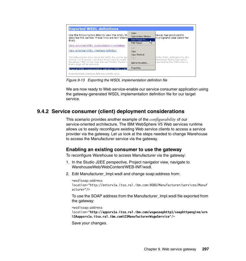
Figure 9-13 Exporting the WSDL implementation definition file
We are now ready to Web service-enable our service consumer application using the gateway-generated WSDL implementation definition file for our target service.
9.4.2 Service consumer (client) deployment considerationsThis scenario provides another example of the configurability of our service-oriented architecture. The IBM WebSphere V5 Web services runtime allows us to easily reconfigure existing Web service clients to access a service provider via the gateway. Let us look at the steps needed to change Warehouse to access the Manufacturer service via the gateway.
Enabling an existing consumer to use the gatewayTo reconfigure Warehouse to access Manufacturer via the gateway:
1. In the Studio J2EE perspective, Project navigator view, navigate to WarehouseWeb/WebContent/WEB-INF/wsdl.
2. Edit Manufacturer_Impl.wsdl and change soap:address from:
<wsdlsoap:address location="http://entsrv1w.itso.ral.ibm.com:9080/Manufacturer/services/Manufacturer"/>
To use the SOAP address from the Manufacturer_Impl.wsdl file exported from the gateway:
<wsdlsoap:address location="http://appsrv1a.itso.ral.ibm.com/wsgwsoaphttp1/soaphttpengine/urn%3Aappsrv1a.itso.ral.ibm.com%23ManufacturerWsgwService"/>
Save your changes.
Chapter 9. Web service gateway 297

3. To allow Warehouse to access all three manufacturers via the gateway, we also changed the following WSDL files in the same way:
– ManufacturerB_Impl.wsdl in WarehouseWeb/WebContent/WEB-INF/wsdl
– ManufacturerC_Impl.wsdl in WarehouseWeb/WebContent/WEB-INF/wsdl
4. To allow Manufacturers to access the WarehouseCallBack service via the gateway, we just changed the callbackEndpoint environment variable in the WarehouseWeb module to the SOAP address from the WarehouseCallBack_Impl.wsdl file exported from the gateway. Figure 9-14 shows this variable in the WebSphere Studio Deployment Descriptor Editor.
Figure 9-14 Environment Variable for WarehouseCallBack endpoint
When submitting a purchase order, Warehouse passes the callback endpoint address to Manufacturer in the SOAP header shown in Example 9-2.
Example 9-2 SOAP request for submitPO operation
<soapenv:Envelope xmlns:soapenv="http://schemas.xmlsoap.org/soap/envelope/" xmlns:soapenc="http://schemas.xmlsoap.org/soap/encoding/" xmlns:xsd="http://www.w3.org/2001/XMLSchema" xmlns:xsi="http://www.w3.org/2001/XMLSchema-instance">
<soapenv:Header><Configuration
xmlns="http://www.ws-i.org/SampleApplications/SupplyChainManagement/2002-08/Configuration.xsd">
Note: Replacing the endpoint address with the gateway address in the client WSDL works well in our case. You need to be careful with this approach in more complex scenarios. The safest approach is to regenerate the Web service client from the gateway WSDL.
However, regenerating the Web service client from the gateway WSDL usually means the class names of the generated client stubs will also change. You will then need to change the client application to use the new stub class names.
298 Patterns: Service-Oriented Architecture and Web Services

<UserId>4309d4eb:fb44c05435:-7ffb</UserId></Configuration><StartHeader
xmlns="http://www.ws-i.org/SampleApplications/SupplyChainManagement/2002-10/Manufacturer/CallBack">
<conversationID>7</conversationID>
<callbackLocation>http://appsrv1a.itso.ral.ibm.com/wsgwsoaphttp1/soaphttpengine/urn%3Aappsrv1a.itso.ral.ibm.com%23WarehouseCallBackWsgwService</callbackLocation>
</StartHeader></soapenv:Header><soapenv:Body>
<PurchaseOrder xmlns="http://www.ws-i.org/SampleApplications/SupplyChainManagement/2002-10/ManufacturerPO.xsd">
<orderNum>7</orderNum><customerRef>A12345-9876543-xyz</customerRef><items>
<Item><ID>605004</ID><qty>46</qty><price>100.0</price>
</Item></items><total>0.0</total>
</PurchaseOrder></soapenv:Body>
</soapenv:Envelope>
After making these changes, it is just a matter of redeploying the Warehouse application, as described in “Deploying the new consumer” on page 300.
Enabling a new consumer to use the gatewayThe WebSphere Studio Web Service Client wizard can be used to Web service enable an application needing to access a service via the gateway.
You can use the same procedure as that described for Warehouse as a consumer of Manufacturer in 6.3.4, “Service consumer (client) development considerations” on page 200.
In this case, use the Manufacturer_Impl.wsdl file exported from the gateway, as described in “Exporting the WSDL file” on page 296, rather than the original Manufacturer_Impl.wsdl.
Chapter 9. Web service gateway 299

Deploying the new consumerTo deploy the new Warehouse, a consumer of the Manufacturer service, we performed the following steps:
1. In WebSphere Studio, export the Warehouse project as an EAR file.
2. Copy the exported EAR to the application server that you want to deploy to.
We recommend that you copy the EAR file to the <WAS_HOME>/installableApps folder on the application server.
3. Install the Warehouse application on a WebSphere Application Server instance. You can use the same procedure as described for Manufacturer.ear in “Deploying a service” on page 215.
Be sure to select the Deploy WebServices option if you did not regenerate the Web service clients in Studio.
9.4.3 Testing considerationsIn addition to the considerations discussed in “Testing considerations” on page 210, the Diagnostic Trace Service can be used to enable tracing of application server components. The following trace specification can be used when diagnosing Web Services Gateway problems:
com.ibm.wsgw.*=all=enabled:org.apache.wsif.*=all=enabled:com.ibm.ws.webservices.*=all=enabled
300 Patterns: Service-Oriented Architecture and Web Services

Chapter 10. e-business on demand and Service-oriented architecture
In this, the last chapter of the book, we give you a brief introduction to IBM’s e-business on demand vision and strategy. We describe in further detail the on demand operating environment, and how it can be realized through service-oriented architecture. IBM offers industry-leading products and services to support the journey from e-business to the next evolution, e-business on demand. And in line with this transition, we conclude with a look at the current IBM on demand technologies.
10
© Copyright IBM Corp. 2004. All rights reserved. 301
10.1 e-business on demandIn October of 2002, IBM announced its vision of the next major phase of e-business adoption and called it e-business on demand. In fact, e-business on demand is not just a vision, nor is it new. It is a statement of IBM’s belief of how businesses will need to transform themselves to be successful. Businesses will have to adapt to cope with ever-increasing pressures from competition and other factors associated with the global economy. This implies a transformation to a fully integrated business across people, processes, and information, including suppliers and distributors, customers and employees.
IBM defines an on demand business as an enterprise whose business processes, integrated end-to-end across the company and with key partners, suppliers, and customers, can respond with speed to any customer demand, market opportunity, or external threat.
There are four key attributes of an on demand business:
� Responsive: Able to sense and respond to dynamic, unpredictable changes in demand, supply, pricing, labor, competition, capital markets, and the needs of its customers, partners, suppliers, and employees.
� Variable: Able to adapt processes and cost structures to reduce risk while maintaining high productivity and financial predictability.
� Focused: Able to concentrate on its core competencies and differentiating capabilities.
� Resilient: Able to manage changes and external threats while consistently meeting the needs of all of its constituents.
As shown in Figure 10-1 on page 303, IBM has identified the following three stages of the e-business on demand evolution that most organizations are currently going through:
� Access: Transform the communication with Internet access, publish static information, and Web-enable simple processes.
� Enterprise Integration: Transform the business processes by integrating internal processes and external value nets.
� on-demand: Transform the business model to manage the operations dynamically, allowing the business to rapidly respond to market changes and opportunities, as well as deliver customized products and services in real-time.
302 Patterns: Service-Oriented Architecture and Web Services
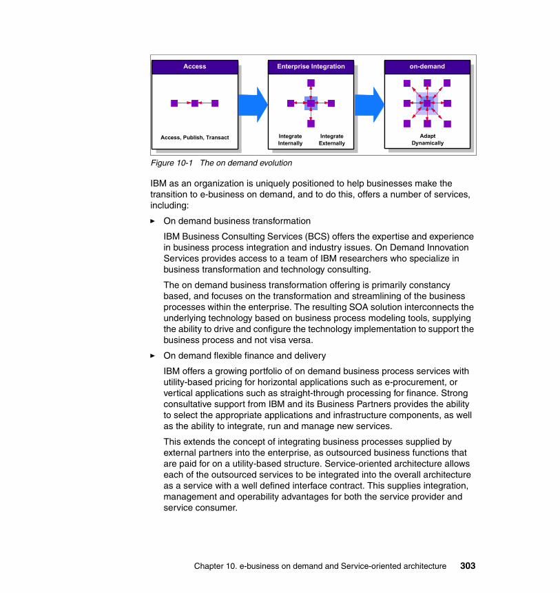
Figure 10-1 The on demand evolution
IBM as an organization is uniquely positioned to help businesses make the transition to e-business on demand, and to do this, offers a number of services, including:
� On demand business transformation
IBM Business Consulting Services (BCS) offers the expertise and experience in business process integration and industry issues. On Demand Innovation Services provides access to a team of IBM researchers who specialize in business transformation and technology consulting.
The on demand business transformation offering is primarily constancy based, and focuses on the transformation and streamlining of the business processes within the enterprise. The resulting SOA solution interconnects the underlying technology based on business process modeling tools, supplying the ability to drive and configure the technology implementation to support the business process and not visa versa.
� On demand flexible finance and delivery
IBM offers a growing portfolio of on demand business process services with utility-based pricing for horizontal applications such as e-procurement, or vertical applications such as straight-through processing for finance. Strong consultative support from IBM and its Business Partners provides the ability to select the appropriate applications and infrastructure components, as well as the ability to integrate, run and manage new services.
This extends the concept of integrating business processes supplied by external partners into the enterprise, as outsourced business functions that are paid for on a utility-based structure. Service-oriented architecture allows each of the outsourced services to be integrated into the overall architecture as a service with a well defined interface contract. This supplies integration, management and operability advantages for both the service provider and service consumer.
Access Enterprise Integration on-demand
Access, Publish, Transact IntegrateInternally
IntegrateExternally
AdaptDynamically
Chapter 10. e-business on demand and Service-oriented architecture 303

� On demand operating environment
IBM has been an early advocate of open standards, leading with Linux and Web services. IBM also maintains an industry leading family of middleware products, which are critical to business process integration, workflow and systems management, and data and content management. IBM provides a broad portfolio of storage and server offerings, which can scale instantly, add capacity and processing power on the fly, and which possess advanced self-managing capabilities. Finally, IBM is leading the industry charge to reduce IT complexity through autonomic computing initiatives, and is driving business adoption of Grid computing as the next evolution of the Internet, allowing companies to more easily tap into Web-based applications to share distributed computing resources.
For an organization to successfully attain and maintain an on demand business, it must build an IT infrastructure that is designed to specifically support the business’ goals. The rest of this chapter focuses on this infrastructure, the e-business on demand operating environment, and how it can be supported using a service-oriented architecture.
For more information related to IBM’s on demand vision and strategy, please visit the IBM on demand home page:
http://www.ibm.com/ondemand
10.2 The on demand operating environmentSo what is an on demand operating environment? It is not a specific set of hardware and software. Rather, it is an environment that supports the needs of the business, allowing it to become and remain responsive, variable, focused, and resilient.
An on demand operating environment unlocks the value within the IT infrastructure to be applied to solving business problems. It is an integrated platform, based on open standards, to enable rapid deployment and integration of business applications and processes. Combined with an environment that allows true virtualization and automation of the infrastructure, it enables delivery of IT capability on demand.
An on demand operating environment must be:
� Flexible� Self-managing� Scalable� Economical� Resilient
304 Patterns: Service-Oriented Architecture and Web Services

� Based on open standards
Table 10-1 provides some examples of how a service-oriented architecture can support these characteristics of an on demand operating environment.
Table 10-1 Relationship between the on demand operating environment and SOA
IBM provides on demand operating environment offerings that can be categorized into three primary areas:
� Integration: Provides the facilities to gain a unified view of processes, people, information, and systems
on demand operating environment
Service-oriented architecture
Flexible Discoverable: The needed service can be found at design time or at runtime, not only by unique identity but also by interface identity and by service kind. This permits the architecture to be flexible and responsive to change, both in the business process and to other services.
Self-managing Although services in themselves are not self-managing, the SOA infrastructure and middleware can provide self-management capabilities when using products such as IBM WebSphere and Tivoli®.
Scalable Interface-based design: Multiple instances of services can be provided to enable scalability and failover.
Economical Single instance: An important goal of service-oriented architecture is to identify and establish single, always running instances of the required business services. This avoids inefficient duplication of business function around the enterprise.
Resilient Coarse-grained: Operations on services are frequently implemented to encompass more functionality and operate on larger data sets. Architectures relying on complex, fine-grained interactions tend to be more fragile.Asynchronous: SOAs can use asynchronous messaging to improve the resilience of the business process.
Based on open standards
Loosely coupled: Services can interact with other services and service consumers independently of programming language, protocol, or platform. This flexibility is enabled with Web services, for example, through the use of open standards such as XML, SOAP, and HTTP.
Chapter 10. e-business on demand and Service-oriented architecture 305

� Automation: Overcomes the complexity of systems management to enable better use of assets, improved availability and resiliency, and reduced operating costs
� Virtualization: Simplifies deployment and improves use of computing resources by hiding the details of the underlying hardware and system software, allowing for consolidation and the ability to adapt to changing demand
The value of the on demand operating environment is in the ability to dynamically link business processes and policies with the allocation of IT resources using the offerings across all of these categories. In the on demand operating environment, resources are allocated and managed without intervention, enabling resources to be used efficiently based on business requirements. Having flexible, dynamic business processes increases the ability to grow and manage change within the business.
Figure 10-2 Overview of an on demand operating environment
Figure 10-3 on page 307 provides an overview of the key components of an on demand operating environment. We look at each of these categories in relation to service-oriented architecture next.
IntegrationIntegration
AutomationAutomation VirtualizationVirtualization
Flexible, dynamicbusiness processes
Assets usedefficiently basedon businessrequirements
Resources allocatedand manageddynamically withoutintervention
Business policies driveIT resource allocation
306 Patterns: Service-Oriented Architecture and Web Services

Figure 10-3 Key components
10.2.1 IntegrationIntegration is the efficient and flexible combination of resources to optimize operations across and beyond the enterprise. Integration crosses people, processes and information, and although not a new concept, the value of investing in such integration, and the ability to apply the technologies and products that truly enable such integration, has never been higher.
PeopleThe IT environment must enable the business to interact with employees, customers, business partners, and suppliers by supporting integrated business processes, collaboration, and data sharing. No matter the role of the user, the operating environment must:
� Simplify the end-user experience.
� Provide secure, role-based interactions.
� Standardize access to applications.
IntegrationIntegration
AutomationAutomation
VirtualizationVirtualization
Ope
n St
anda
rds-
Base
d
BusinessObjectives
andPolicies
Integration of People - Process - InformationAnywhere, Anytime, from Any Device
Application Development, Deployment & Maintenance
TransactionalProcessesCollaboration Information
Management
Policy-Based Orchestration
Virtualization Engine
Availability Security Optimization Provisioning
Servers Storage DistributedSystems Network
Chapter 10. e-business on demand and Service-oriented architecture 307

� Allow users access to the processes and data they require anytime and anyplace.
Let us review the above criteria in the context of a service-oriented architecture.
Simplify end-user experienceAn on demand operating environment provides the tools and facilities to make employees more productive, and to make it easier for customers, suppliers, and partners to do business with the company.
In a fast changing business environment, it is important for the underlying business systems to be adaptable to changes in the business process. Applications, internal departments, and partner systems need to be integrated to the enterprise to support the end-to-end process, with as little effort and complexity as possible. Using a service-oriented architecture to separate the interfaces of applications and systems it is possible to implement, replace or revoke services with minimum impact to the user experience. The enterprise can be extended to include support for business partner systems by agreeing on a well defined interface contract, independently of the implementation approach and underlying platform.
Secure role-based interactionsProviding people with what they need, when they need it, requires a solution that includes integrated, role-based policies. Such facilities help ensure privacy and the protection of data and resources while meeting the dynamic demands of the users.
By implementing a layered service-oriented architecture, a common interface is used by all applications and services within the enterprise for access: The service bus. With a more traditional enterprise architecture the security is generally implemented either on the front end, or as a complex implementation of components distributed across the entire system with a high degree of dependency on each other. It becomes difficult to maintain consistent security policy across individual applications. Through the implementation of an SOA and a security service layer, such as WS-Security, a common role-based security model can be introduced independent of the underlying applications. Additionally, this model allows changes in business security policy without any change required to or impacting the underlying individual applications and integrations.
Standardize accessAs the business changes to meet market pressures, new applications must be made available to enable users to become productive without extensive training. By providing standardized interfaces to applications and using facilities such as portals to gain access to applications, users can quickly adapt to new
308 Patterns: Service-Oriented Architecture and Web Services

applications. This will also ensure that resources within the company can quickly be redeployed as necessary to meet changing demands.
This is achieved by separating the presentation logic from the underlying applications and data storage. SOA provides a presentation layer between the user and the underlying services. This way all presentation logic is decoupled from the functions supplied and the associated data. Services are also reusable by any number of different user interfaces, based on a single service interface.
Access to required processes and dataWhether using a desktop system, laptop, or other devices, such as ATMs, PDAs, cell phones, and so on, users demand access to applications and information from anywhere at anytime. An on demand operating environment provides a secure, yet flexible infrastructure to support local, remote, and mobile users through whatever devices they might be using.
By extending the presentation service layer described above, the service-oriented architecture adopted by the enterprise can be tailored to support new requirements for client type support, with no changes required to any of the existing business systems.
ProcessesBusiness can no longer afford to develop and maintain isolated, vertical business processes. An on demand business must manage and coordinate the entire enterprise horizontally, and the IT infrastructure needs to be an enabler not a barrier. An on demand operating environment supports:
� A consistent modelling of business processes
� Integration of applications
� External connectivity
Now let us review the above criteria for processes’ support within an on demand operating environment in the context of a service-oriented architecture.
Consistent modelingBy providing a consistent model of business processes, you can more easily adapt applications as the business needs change. Consistent modelling is independent of underlying product implementations; therefore, the model can persist even when more cost-effective products might be chosen on which to build the solution.
Modeling a business process in a way that is abstracted from the implemented technologies makes it easier to adapt to changing business conditions. Using a consistent modeling approach simplifies communication between all parties
Chapter 10. e-business on demand and Service-oriented architecture 309

involved in the business process. In addition, models can be shared between partners without dictating the development tools or runtime environment that each of the partners in the process must use. The service-oriented approach facilitates the use of tools for implementing a business process from a model defining how a set of services needs to be orchestrated and composed.
Integration of applicationIt is no longer practical to build vertical solutions in a vacuum, independent of, and without consideration of, other applications in other parts of the business. Just as a business must integrate all of its business processes to run more efficiently and be responsive to changing demands, an on demand operating environment provides the infrastructure needed to allow applications to be integrated by using common standards and open technologies. As new, unforeseen opportunities and requirements surface, applications that previously might have seemed unrelated will need to be quickly and efficiently integrated.
The Enterprise Service Bus concept, covered in “Enterprise Service Bus” on page 38, will be a key enabler for this requirement. It provides the ability for all applications, both intra- and inter-enterprise to appear on the network as a set of services, through the use of well defined interface contracts based on industry standard technologies.
Another dramatic benefit of the Enterprise Service Bus is the ability to leverage legacy systems. We can integrate existing legacy systems into the SOA by wrapping these systems in a well structured interface contract, with minimal changes to the legacy system applications.
External connectivityBy conforming to standards, applications and processes can be connected to other external applications and processes. As the business changes, new partners arise, or mergers occur, the cost and time associated with rewriting applications or redesigning processes to be compatible with existing tools is unacceptable in an on demand world. By planning for and enabling the integration and interconnectivity of applications as provided in an on demand operating environment, the business can be more responsive to changes as they occur.
Just as with the integration of applications within the enterprise as defined in “Integration of application” on page 310, the principle can be extended to support the integration of applications published as services by business partners and other external entities with minimal requirement for additional development effort, allowing for a faster response time to changes and new demands.
310 Patterns: Service-Oriented Architecture and Web Services

InformationInformation integration enables real-time access to diverse and distributed information across and beyond the enterprise. Information can reside in multiple source systems (Oracle databases, Microsoft spreadsheets, flat files, and so on) and be distributed across a variety of operating environments (Microsoft Windows NT, Linux, UNIX, z/OS®, for example). By better integrating information, organizations can increase efficiencies, better serve customers and suppliers, make better decisions, and respond more quickly to new opportunities or threats.
The on demand operating environment provides:
� A greater range of information access strategies to best match business value
� Access to diverse and distributed information as though it were in a single source, whether or not it is
� Data consolidation
Again, let us review the above criteria for information in the context of a service-oriented architecture.
Greater range of information access strategiesAn on demand environment must allow companies to either consolidate information onto a single platform or to access the data in place depending on business needs.
Whatever strategy the business defines for accessing data and information inside and outside of the enterprise, the underlying architecture and infrastructure must support access in a heterogeneous environment containing a large number of applications and data stores. To facilitate this requirement, the on demand operating environment needs to be able to dynamically locate, extract and manipulate information on a just-in-time basis.
The Enterprise Service Bus approach, discussed in “Enterprise Service Bus” on page 38, will be a key enabler for the on demand requirement to supply the enterprise with a comprehensive data access strategy.
Access to informationAn on demand environment enables data and content to be accessed independently of its location or platform. This allows for access to real-time information, information that resides outside of the enterprise, and information that cannot be moved. The ability to access data without impact to the existing IT infrastructure enables corporations to gain greater return on existing information assets.
Chapter 10. e-business on demand and Service-oriented architecture 311

The ability to introduce new sources of information or data without impacting existing applications, and within a reduced time scale, is imperative to ensure that the organization can respond with speed to any customer demand, market opportunity, or external threat.
The service-oriented architecture approach allows applications or data stores to be wrapped as a service and made available for invocation by any other service. The enterprise is then able to rapidly gain access to new information and data when required, with minimal impact on the existing applications.
Data consolidationWhere data needs to be consolidated for greater performance and availability, an on demand environment provides data placement management. This allows information to be consolidated or cached when business requirements demand it.
To better understand the value of a service-oriented architecture when discussing data consolidation within an on demand operating environment, it would be easiest to review each of the above mentioned alternatives for data placement management independently.
� Consolidation. The consolidation of data to a central repository is not unique to the on demand operating environment. As organizations extend through mergers and acquisitions, the requirement to merge independent data repositories such as customer and employee information becomes a necessity.
Although a service-oriented architecture will not supply any direct support for the management of data consolidation or tools for data migrations, it will supply a robust infrastructure to enable the enterprise to rapidly deploy new information and data sources to be harvested for consolidation.
� Caching. In situations where the information in question resides outside of the enterprise and/or is for reference or regarded as volatile data, it would generally be more appropriate to locally cache the data for a defined length of time or until no longer valid. Let us consider the standard Web services example of a stock quote request. Unless the data was regarded as part of the core business function, it would be unrealistic or impractical for the enterprise to locally manage a repository of constantly changing stock values, and advisable to request the current values of a complete portfolio from the external supplier when required and on demand. The retrieved data could then be cached locally until expired or invalid, to facilitate a faster response time for subsequent requests by other users or for other values of the currently cached portfolio.
312 Patterns: Service-Oriented Architecture and Web Services
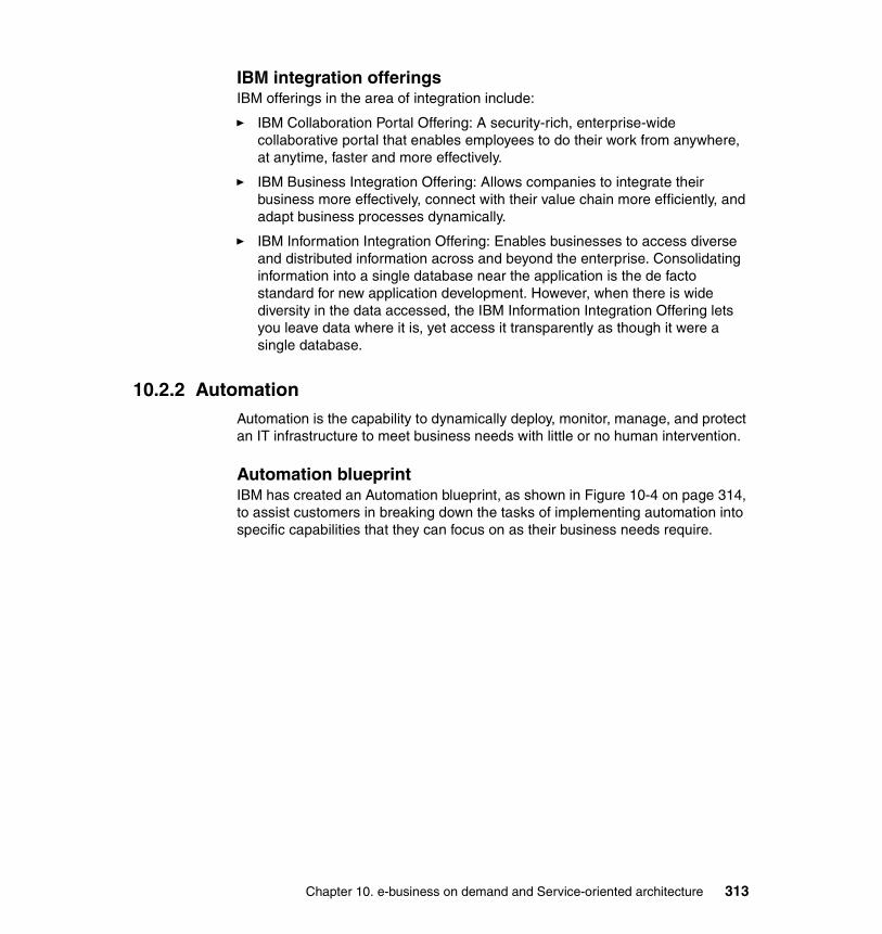
IBM integration offeringsIBM offerings in the area of integration include:
� IBM Collaboration Portal Offering: A security-rich, enterprise-wide collaborative portal that enables employees to do their work from anywhere, at anytime, faster and more effectively.
� IBM Business Integration Offering: Allows companies to integrate their business more effectively, connect with their value chain more efficiently, and adapt business processes dynamically.
� IBM Information Integration Offering: Enables businesses to access diverse and distributed information across and beyond the enterprise. Consolidating information into a single database near the application is the de facto standard for new application development. However, when there is wide diversity in the data accessed, the IBM Information Integration Offering lets you leave data where it is, yet access it transparently as though it were a single database.
10.2.2 AutomationAutomation is the capability to dynamically deploy, monitor, manage, and protect an IT infrastructure to meet business needs with little or no human intervention.
Automation blueprintIBM has created an Automation blueprint, as shown in Figure 10-4 on page 314, to assist customers in breaking down the tasks of implementing automation into specific capabilities that they can focus on as their business needs require.
Chapter 10. e-business on demand and Service-oriented architecture 313
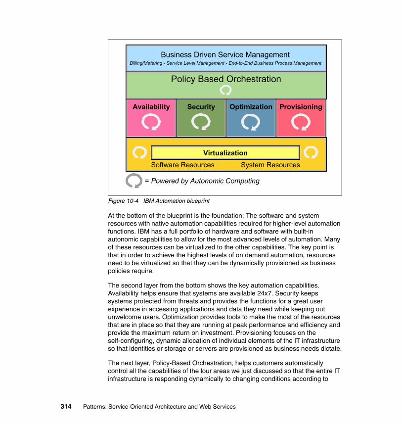
Figure 10-4 IBM Automation blueprint
At the bottom of the blueprint is the foundation: The software and system resources with native automation capabilities required for higher-level automation functions. IBM has a full portfolio of hardware and software with built-in autonomic capabilities to allow for the most advanced levels of automation. Many of these resources can be virtualized to the other capabilities. The key point is that in order to achieve the highest levels of on demand automation, resources need to be virtualized so that they can be dynamically provisioned as business policies require.
The second layer from the bottom shows the key automation capabilities. Availability helps ensure that systems are available 24x7. Security keeps systems protected from threats and provides the functions for a great user experience in accessing applications and data they need while keeping out unwelcome users. Optimization provides tools to make the most of the resources that are in place so that they are running at peak performance and efficiency and provide the maximum return on investment. Provisioning focuses on the self-configuring, dynamic allocation of individual elements of the IT infrastructure so that identities or storage or servers are provisioned as business needs dictate.
The next layer, Policy-Based Orchestration, helps customers automatically control all the capabilities of the four areas we just discussed so that the entire IT infrastructure is responding dynamically to changing conditions according to
Availability Security Provisioning
= Powered by Autonomic Computing
Optimization
Software Resources System ResourcesVirtualization
Policy Based Orchestration
Business Driven Service ManagementBilling/Metering - Service Level Management - End-to-End Business Process Management
314 Patterns: Service-Oriented Architecture and Web Services

defined business policies. This orchestration builds on the best practices of the customer’s collective IT experience and helps to ensure that complex deployments are achieved with speed and quality.
Finally, Business Driven Service Management capabilities provide the tools needed to manage service levels, meter system usage and bill customers for that usage, as well as model, integrate, connect, monitor, and manage business processes end-to-end for complete linkage of IT and business processes.
Autonomic computing and automationThere has been a lot of discussion within the industry about autonomic computing. So far we have introduced automation as one of the key goals of an on demand operating environment. It is natural to ask the question, “What is the difference between autonomic computing and automation?”
Automation is the goal, the benefit customers will achieve, and autonomic computing is the discipline and enabling technology that gets you there. Autonomic computing is the driver for the development of advanced technologies (autonomic technologies) that are embodied by the IBM automation offerings, as well as other products.
Autonomic computing provides the technology to enable information systems to be self-managing. These self-managing characteristics combine to deliver the automation required of an on demand operating environment. Autonomic technologies are the “inside” components, and automation is the end result that is visible “outside” to the user.
Autonomic computing is a fundamental underpinning for automation offerings.
Automation requirementsAn on demand operating environment provides automated capabilities to address policy-based orchestration and provisioning.
Policy-based orchestration is all about providing an end-to-end IT service that is dynamically linked to business policies, allowing the ability to adapt to changing business conditions. Having each individual element of an IT system respond to change is definitely a great start, but in the end, to truly be an on demand business requires orchestration of the automation of multiple elements of the systems so that the entire IT infrastructure is responding as it should to changes in business policies or conditions. For example, if a customer’s order entry application suddenly experiences a surge in load, just allocating more CPU may not be enough; it may also need additional storage, more network capacity, and even additional servers and new users to handle the increased activity. All of these changes must be orchestrated so that the dynamic allocation of multiple resource elements occurs seamlessly. The policy-based orchestration
Chapter 10. e-business on demand and Service-oriented architecture 315

component of the on demand operating environment works across the following areas:
� Provisioning� Availability� Security� Optimization
It is important to understand that automation within an on demand operating environment is predominantly obtained through the correct implementation of hardware and management services such as orchestration provisioning software. Where a service-oriented architecture can deliver additional advantages in the area of automation within the on demand operating environment, is in supplying a robust architecture and infrastructure to ensure that the business can change it’s response from “just in case” provisioning, where expensive resources such as backup systems for disaster recovery sit idle until needed, to “on demand” provisioning, in which resources that support lower priority work can be re-purposed to meet urgent needs of higher priority work in minutes.
Let us take a closer look at the key areas of the automation component within the on demand operating environment.
ProvisioningProvisioning is the end to end capability to automatically deploy and dynamically optimize resources in response to business objectives in heterogeneous environments.
Provisioning helps to respond to changing business conditions by providing the ability to dynamically allocate resources to the processes that most need them, driven by business policies. Provisioning of individual elements, such as identities, storage, servers, applications, operating systems, and middleware, is a critical step to being able to then orchestrate the entire environment to respond to business needs, on demand.
AvailabilityAvailability means systems have to be available 24 hours a day, 7 days a week, 365 days a year to meet the requirements of global business. To meet that requirement without employing huge amounts of human capital, automation can help by monitoring your systems and automatically taking actions to maintain high availability without human intervention, before issues become problems.
To provide the kind of infrastructure that supports an on demand business requires a complex set of underlying technologies. However, to support a flexible and responsive business, the components must be able to be reconfigured,
316 Patterns: Service-Oriented Architecture and Web Services

managed, and applied to the business objective. This task is immensely complex and cannot be accomplished without automation.
SecuritySecurity is the ability to ensure the business is protected from threats, that the right users get to the right information at the right time, and that the automation that helps these functions occurs without expensive help desk or administrator attention. As businesses open up to potentially millions of users, it is critical that welcomed users are identified and provided with highly satisfying user experiences. It is equally critical that unwelcome users are also identified and prevented from accessing systems, causing damage, or even stealing other users’ information. Security is certainly a key focal point of most businesses today.
OptimizationOptimization helps businesses make the best use of their existing resources and helps ensure all resources are running at peak performance and efficiency. It is critical to make the best use of the resources they already have, so we focus heavily on heterogeneous, cross-platform support that integrates with what is already installed. Tight IT budgets and the need to respond quickly drive businesses to insist that their current investments are optimized.
As with integration and virtualization, automation is not a new concept. But an on demand operating environment requires new levels of automation that can provide the flexibility and responsiveness to support an on demand business.
IBM automation offeringsIBM offerings in the area of automation include:
� IBM Optimization Offering for zSeries®: provides a highly automated environment for WebSphere workload management with IBM eServer zSeries and z/OS.
� IBM iSeries™ Enterprise Edition: Incorporates a set of software licensing and hardware features designed to help meet the particular demands of a small, medium or large enterprise, with services and educational vouchers to help get started quickly. The iSeries provides an on demand environment capable of running multiple operating systems simultaneously and dynamically adjusting to changing requirements.
� IBM User Provisioning Offering: Extends identity management to incorporate automated provisioning of identities and central enforcement of access control.
� IBM Web Server Provisioning Offering: Delivers infrastructure automation, including Web infrastructure monitoring driving automatic provisioning;
Chapter 10. e-business on demand and Service-oriented architecture 317

“Agnostic” network and storage hardware requirements (subsystems and SAN); protection against server failures and data loss and is integrated with the IBM middleware stack.
� IBM Storage Provisioning Offering: Provides an intelligent console with a set of business policy driven automated tools for managing storage capacity, availability, events and assets in an enterprise environment. It can help identify, evaluate, predict and control storage management assets. It can detect potential problems and automatically make adjustments based on business policies and actions defined.
� IBM Availability Management Offering: Enables management of IT resources within the context of business priorities, managing the availability and performance of critical business systems and web environment. Monitoring your infrastructure and pro actively avoiding system failures and taking automated actions to resolve potential problems.
� IBM Security Event Management Offering: Extends the value of traditional systems event management with the inclusion of security events, providing a holistic view of the health of the IT infrastructure and helping you actively monitor, correlate and quickly respond to IT security threats across your business.
� IBM Tivoli Autonomic Monitoring Engine Offering: Delivers self-healing capabilities today by delivering a set of IT resource monitors that incorporate automated best practices to detect errors and an underlying engine that analyzes errors, correlates into root cause and initiates corrective action.
10.2.3 VirtualizationVirtualization is the process of presenting computing resources in ways that users and applications can easily get value out of them, rather than presenting them in a way dictated by their implementation, geographic location, or physical packaging.
By providing an on demand operating environment where resources can be used efficiently based on business requirements, virtualization can improve working capital and asset utilization.
From the service-oriented architecture perspective, virtualization is provided in the location transparent and loosely coupled interface specifications. The overall business system is no longer dependant on the implementation, location or packaging of a service, but rather the interface contract to which the application or service can be invoked.
Let us look at how virtualization enables the sharing of resources.
318 Patterns: Service-Oriented Architecture and Web Services

ServersBy building an environment where the hardware and systems software are hidden from the users and applications, servers can be shared across business units, processes, and applications, allowing for consolidation.
StorageProviding access to data, regardless of its physical location or file structure, provides economies through cost-effective storage media and more efficient data sharing.
Distributed systemsTaking advantage of advances in distributed systems such as grid computing allows resources across the enterprise (individual systems, servers, clusters, and storage devices) to be shared and dynamically allocated to meet business needs. This dynamic allocation allows for higher utilization of resources, resulting in costs savings, as well as increased capability to meet unforeseen processing requirements by allocating available resources on demand.
NetworkingAs the world has become networked together through the Internet, it is critical to be able to manage and control portions of the network, which might even be shared between among different enterprises, as individual or virtual networks. This includes technologies such as VPNs, VLANs, IP virtualization, Web services gateway and more.
In an on demand operating environment, virtualization of resources within the IT infrastructure provides many benefits. Where the underlying hardware and system software is hidden from the users and applications, an open standards-based infrastructure can be deployed to simplify:
� Systems administration: Rather than having individual servers dedicated to specific applications, and therefore specialized support staffs, virtualization allows for a common environment that can simplify the overall administration requirements, while allowing resources to be allocated as needed by the business.
� Asset portfolio management: An on demand operating environment provides a common environment for running applications, while maintaining independence from underlying hardware and systems software. In this environment, assets can be easily managed, changed, and reallocated without requiring changes to the applications. Likewise, applications can be modified and enhanced to meet business needs without necessarily requiring changes to the underlying systems. If additional computing power or storage is required, it can often be provided through available resources.
Chapter 10. e-business on demand and Service-oriented architecture 319

� Cost structure: By utilizing virtualization to dynamically allocate system and storage resources, the overall cost of hardware and software can be controlled.
Overall, a virtualized environment provides simplified access to data and IT resources on demand. Idle capacity can be used to meet unforeseen demand and to reduce the need to purchase additional hardware and software. The savings realized from reduced capital expenditures can be reinvested in other areas to help grow the business.
Virtualization in different forms has been around for at least 40 years, dating back to the days of the S/360™. However, with the maturing of grid technologies and SANs, we are now moving from the days of virtual storage or even virtual machines to virtual computing environments, allowing businesses to gain even larger financial and business advantages.
IBM virtualization offeringsIBM offerings in the area of virtualization include:
� IBM TotalStorage® Virtualization Family: Helps customers with complex storage environments, who are looking to mask complexity and share storage capacity across heterogeneous systems, reduce their management and operational costs.
� IBM Entry Virtualization Server Offering: Designed to target customers who need to simplify their IT infrastructure as a first start toward the virtualization of their IT resources.
� IBM Server Allocation for WebSphere Application Server: Maximizes utilization of existing computing resources. This offering provides the capability to dynamically provide workload management of multiple applications across multiple server clusters, a first for any application server product.
� IBM Grid Offering for Analytic Acceleration - Financial Markets: Helps enhance competitiveness and agility in the financial trading market. IBM uses a comprehensive approach to help determine the most appropriate combination of technologies for analytic acceleration in financial services.
10.3 Service-oriented architecture for on demandSo far we have taken a high level view of IBM’s e-business on demand vision and strategy “The new agenda”, followed by a closer look at the on demand operating environment, and the associated offerings provided by IBM. Next, we will investigate how we can implement an on demand operating environment using a service-oriented architecture, and the appropriate IBM on demand technologies.
320 Patterns: Service-Oriented Architecture and Web Services

Figure 10-5 shows how the characteristics of a service-oriented architecture support the on demand operating environment by supplying a flexible underlying architecture and infrastructure.
Figure 10-5 Supporting the on demand operating environment with SOA
The service-oriented architecture supports the three categories of the IBM on demand operating environment (integration, virtualization and automation) as an integrated unit spanning the complete enterprise system. By implementing a service-oriented architecture that is flexible, self-managing, scalable, economical, resilient and based on open standards, we can assist the enterprise in becoming:
� Responsive
� Variable
� Focused
Let us start by taking a look at the landscape of today’s business environment.
10.3.1 The starting pointIn many enterprises of today, applications are tightly coupled, component oriented, with a high dependency on each others deployment characteristics, and have a strong requirement to be aware of the location and platform of all other integrated information providers. Often implemented as vertical silos to
SOASOA
IntegrationIntegration
VirtualizationVirtualization AutomationAutomation
ArchitecturalCharacteristics
Self-containedModularInteroperabilityLoosely coupledLocation transparent
Chapter 10. e-business on demand and Service-oriented architecture 321

facilitate the business functions of individual departments, and then if required, replicated across departmental and organizational boundaries. These applications frequently drive the business and a number of management capabilities such as customer relationship management, value chain management and enterprise resource management, among others.
As already said, for the enterprise of today to survive, there is a necessity to not only integrate these business systems end-to-end across the company, but also with suppliers, distributors and customers. But in a rapidly changing market, the integration of all enterprise systems both vertically and horizontally is no longer sufficient, and the business will have to be able to adapt to meet demands from both clients and competitors without having to be concerned about the affect this change will have on the health of the supporting IT systems. In a heterogeneous environment of partner systems, legacy systems, packaged applications and in-house developments, the ability to maintain the health of your supporting IT infrastructure and business systems requires a robust architecture. It must supply a stable and structured framework to support the new on demand business, and its operating environment.
10.3.2 Building the on demand operating environmentSo the business has been streamlined by defining the business rules and mapping them to processes that can respond dynamically to changes in your market. The business has defined the new processes that will allow it to control cost across the entire value chain, and stay focused on its core business.
The next step is to define the new environment that is required to support the needs of the transformed business - the on demand operating environment. But just as with the business in general, building the on demand operating environment requires changes in all aspects of IT, from architecture, development, deployment to the ongoing maintenance. The key to starting the transformation to the new operating environment is to first evaluate how well your applications and infrastructure are working across the enterprise today, and determine if there are other better ways of doing things:
� Are your key business processes duplicated vertically across the enterprise?
� Are applications tightly coupled with heavy dependencies with each other, leading to large, costly and risky development should you want to replace one of the applications or change your business processes?
� Will acquisitions or mergers with new partners create complex integration issues, that could have a detrimental impact on your market position giving advantage to your competition?
� Can your operating environment and IT infrastructure respond dynamically with your business to changes in market forces—whether that is customer
322 Patterns: Service-Oriented Architecture and Web Services

needs, supply issues, competitive pressure or something completely unexpected?
But how do you evolve from an IT infrastructure optimized for departmental processes to one that is optimized to support the organizational processes? This is especially difficult when you are dealing with different departmental applications, infrastructure components, application languages, operating systems, servers platforms and storage devices.
In the end you are faced with two options. Rip everything out and replace it all with a new single environment and infrastructure, and then insist that every department within the organization, and every integrated supplier, business partner and potential new acquisitions commit to doing the same.
Alternatively, you can commit to using open industry standards such as Web services and service-oriented architecture, starting out with an appropriate subset of your infrastructure. By implementing an on demand operating environment using a service-oriented architecture, the business can create a level of abstraction between the business process and the technology implemented to support it. Additional by deploying the business functions already supported by existing applications as services with a well defined interface contract, it is possible to separate the physical implementation and location of that service from its published interface.
From the perspective of building the on demand operating environment, it is beneficial to separate it out into the following parts:
� The systems environment: The environment that allows true virtualization and automation of the infrastructure and enables delivery of IT capability on demand. In other words, the infrastructure and hardware.
� The application environment: The integrated platform based on open standards, to enable rapid deployment and integration of business applications and processes. In other words, the software.
� Utility services: Outsourcing infrastructure, business processes and non-core business functions. In other words, stay focused on what the business does best.
The systems environmentThe basic fact is that delivering on demand flexibility requires the infrastructure of today to undertake the next step in the on demand evolution. The systems environment of the client/server era where standalone units with under utilized processing power, over-sized storage capabilities and complex system administration is gone. The new on demand environment relies on just in time provisioning of storage capacity and processor power, by using virtualized storage to manage application and storage growth.
Chapter 10. e-business on demand and Service-oriented architecture 323

The application environmentThis is where the key benefits of a service-oriented architecture can be realized. As any organization that is attempting to integrate their existing applications, information systems, processes and partners will know, this is a challenging, costly and often risky process. Using a service-oriented architecture can greatly simplify the integration of these applications, information and components. The Enterprise Service Bus, discussed in “Enterprise Service Bus” on page 38, is a key service-oriented architecture best practice for enabling the on demand operating environment.
Utility servicesThe third part of the IBM e-business on demand operating environment is the ability to deliver the infrastructure and business processes as a service. By outsourcing both the non-critical systems and business processes, the enterprise is left with a smaller and more streamlined IT infrastructure. Using the open standards of a service-oriented architecture, the enterprise is capable of integrating services to support their business functions, such as human resources and customer relationship management, from external suppliers rapidly with limited impact to existing business systems.
Combine and deliver a three with a service-oriented architecture, and you have created the first iteration of your enterprise e-business on demand operating environment.
For further information on the service-oriented architecture approach, please Chapter 4, “Service-oriented architecture approach” on page 79.
10.3.3 On demand technologiesThere are many technologies, both new and still evolving, that can make the on demand operating environment a reality. It needs to be understood that the on demand operating environment is about a broad set of standards working together to provide a consistent and comprehensive set of facilities.
IBM’s product portfolio now spans five brands which can supply the support required to deliver an on demand service-oriented architecture. Rational provides a powerful set of modeling and development tools; Tivoli includes systems and application management; Lotus brings collaborative services; DB2 adds information integration and data management; while WebSphere provides the foundation for managing transactions and messages, reliably and securely.
In the following sections, we describe some of these technologies and how they apply to on demand computing.
324 Patterns: Service-Oriented Architecture and Web Services

Web servicesWeb services are becoming the standard way to implement a service-oriented architecture. They provide the facilities needed to access corporate data, legacy transaction systems, and new business applications based on standards, such as J2EE, XML, and SOAP. Because of the strict use of standards based interfaces, various Web services can be combined to generate new, integrated applications quickly from existing components.
Grid computingGrid enables the virtualization of widely distributed computing resources, such as processing, storage capacity, data, and network bandwidth, to create a single virtual system, granting users and applications seamless access to vast IT capabilities. Put simply, grid enables customers to get more business value out of what they own.
Through open technologies such as the Globus Toolkit for grid computing and emerging standards such as OGSA and OGSI, grid computing is no longer applicable to only scientific and research projects. Businesses can now seriously look at grid computing as a way to get higher utilization out of their computing and storage resources efficiently and cost effectively. Grid computing enables the dynamic reallocation of resources to meet spikes in demand or changing business requirements.
Autonomic capabilitiesAutonomic capabilities are being developed and integrated with hardware and software products across IBM product lines. Autonomic capabilities are considered an elemental capability that can be used to automate activities for desired business outcomes.
Autonomic capabilities can generally be categorized in the following four areas.
Self-configuringThe ability to dynamically configure components “on the fly” and initialize them in the context of the overall system; this includes the ability to influence relevant changes in other products in the environment.
Self-healingThe ability to recover from a failing component by first detecting improper operations (either proactively through predictions or otherwise) and then initiating corrective action without disrupting applications.
Self-optimizingThe ability of systems or components to efficiently maximize resource allocation and utilization to meet end-user needs without human intervention.
Chapter 10. e-business on demand and Service-oriented architecture 325

Self-protectingThe ability of a component to detect hostile or intrusive behavior as it occurs and take autonomous actions to make itself less vulnerable.
Information integrationInformation integration can take on many forms, from federated databases to content management systems.
Federated databases allow data stored in various database and file systems to be accessed through a common interface such as SQL, hiding the complexity of the environment and the actual location of the data. Using such technologies aid the integration of applications and provides location transparency.
Content management systems enable users and applications to easily find and manage the data they need to perform their jobs.
Blade computersBlade computers allow large numbers of server class computing resources to be tightly packed into small places. This provides more efficient and cost effective use of space, as well as making it easier to physically manage a large number of servers. Using blade computers is one form of consolidation. By utilizing various virtualization and autonomic technologies, these computers can be efficiently reconfigured and reallocated to meet changing demands.
Pervasive device supportProducts such as IBM WebSphere Everyplace® Access simplifies wireless for the enterprise. In one package, it delivers the technology needed to give mobile users access to productivity data and enterprise applications from virtually anywhere, at any time. It supports multiple devices such as PDAs and smartphones from a single platform, based on open standards.
IBM products and software for on demandIBM has broad product support for the on demand operating environment. At the core of IBM’s middleware platform for the support of integration and the Enterprise Service Bus is the WebSphere Application Server and WebSphere MQ, but there are many more.
IBM WebSphereTogether with WebSphere Studio Application Developer, WebSphere Application Server delivers an application server and development environment designed to help the enterprise to deliver e-business applications to run in an on demand operating environment. The WebSphere product family is built on an open standards based platform that supports the J2EE standards, XML, SOAP, UDDI, WS-I profiles and the construction of a service-oriented architecture.
326 Patterns: Service-Oriented Architecture and Web Services

IBM WebSphere MQ connects the enterprise both internally and with external partners to exchange and distribute information securely and reliably. It provides an important alternative messaging transport when basic HTTP is insufficient.
To support the on demand operating environment, WebSphere offers comprehensive solutions to address the following business issues:
� A strong foundation and tools to help reduce business risk
� Business portal software to strengthen business relationships
� Business integration software to optimize operations
For further information on IBM WebSphere software please visit the WebSphere home page at:
http://www.ibm.com/websphere
IBM LotusIBM Lotus is one of the leading industry products for messaging and collaborative support, as well as delivering document management, knowledge discovery, workflow, e-learning and presence awareness.
By componentizing the core parts of the Lotus products and unifying access to each of the components via a common service-oriented interface, the software supplies a template based structure allowing the enterprise to rapidly define on demand workplaces that fit a specific market segment or business need. These enterprise workplaces can be rapidly deployed and integrated with limited impact to the existing infrastructure, which allows the enterprise to react to market needs and respond rapidly.
By using standard IBM development tools such as WebSphere Studio Application Developer, the enterprise can build applications that utilize Lotus based services such as workflow and instant messaging directly in the enterprise system, via a single collaborative API.
For further information on IBM Lotus software please visit the Lotus home page at:
http://www.ibm.com/lotus
IBM DB2 Information ManagementThe IBM DB2 relational database and associated tools such as the DB2 Information Integrator, can support the enterprises requirements for data management and manipulation in a service-oriented architectural on demand operating environment. With extended support for Web Services, DB2 and the data stored within it can be accessed and invoked as a service based on a well defined interface contract such as a WSDL.
Chapter 10. e-business on demand and Service-oriented architecture 327

For further information on IBM DB2 please visit the DB2 home page at:
http://www.ibm.com/db2
IBM Tivoli Configuration Manager and Tivoli Access ManagerTo manage the IT infrastructure within the on demand operating environment, the enterprise must maintain a continual focus on:
� Improving productivity to maintain a competitive advantage
� Obtain new business insight from the existing IT infrastructure
� Build a resilient infrastructure that protects the business assets and data
But at the same time, reduce the number of required skilled resources to manage the infrastructure and reduce the complexity of administration and maintenance.
The role of the IBM Tivoli product family is to manage and secure the on demand operating environment. To do this, Tivoli offers the following solutions to address the fundamental issues faced by the enterprise in managing the on demand operating environment:
� Performance and availability
� Configuration and operations
� Security
� Storage
For further information on IBM Tivoli software please visit the Tivoli Software home page at:
http://www.ibm.com/tivoli
328 Patterns: Service-Oriented Architecture and Web Services

Appendix A. Scenarios lab environment
In this appendix we describe the lab setup we used when deploying our WS-I Supply Chain Management scenarios.
We then explain how to set up our WS-I Supply Chain Management sample in the IBM WebSphere Studio Application Developer development/test environment.
A
© Copyright IBM Corp. 2004. All rights reserved. 329

Lab setupFigure A-1 shows the lab environment we used when deploying our WS-I Supply Chain Management scenarios described in Chapter 6 through Chapter 9.
The chapters covering each scenario are:
� Chapter 6, “HTTP service bus” on page 159
� Chapter 7, “JMS service bus” on page 229
� Chapter 8, “Service directory” on page 251
� Chapter 9, “Web service gateway” on page 279
Figure A-1 Lab environment
Sample application setupTo install the WS-I Supply Chain Management sample application in the IBM WebSphere Studio Application Developer V5.1 for Windows workspace:
1. Download the WS-I Supply Chain Management sample. See Appendix B, “Additional material” on page 333, for details.
Manufacturer ServiceManufacturer
Service
entsrv1w(W2K)
appsrv1a(AIX)12
4
Logging Service
appsrv1l(Linux)
Warehouse Callback Service
appsrv1w(W2K)
Manufacturer Service
UDDIRegistry
Warehouse Service
Web Service Gateway
3
Retailer Service
SCMSampleUI
330 Patterns: Service-Oriented Architecture and Web Services

2. Extract the WS-I Supply Chain Management sample to the required location, for example, C:\ on Windows.
3. Stop WebSphere Application Server if it is running locally.
4. Start Application Developer using the -data option to specify the WS-I Supply Chain Management workspace folder. For example, on Windows:
wsappdev -data C:\workspace
5. Import the WS-I Supply Chain Management projects into your WebSphere Studio workspace:
a. Select File -> Import from the Studio main menu.
b. In the Import window, select Existing Project into Workspace as the import source and click Next.
c. In the next window, click Browse, then navigate to the Build project folder. For example, on Windows:
C:\workspace\Build
Click OK, then click Finish to import the project.
d. Repeat steps a to c for each of the remaining WS-I Supply Chain Management projects:
• LoggingFacility• LoggingFacilityEJB• LoggingFacilityJMS• LoggingFacilityWeb• Manufacturer• ManufacturerB• ManufacturerBEJB• ManufacturerBWeb• ManufacturerC• ManufacturerCEJB• ManufacturerCWeb• ManufacturerEJB• ManufacturerWeb• Retailer• RetailerWeb• SCMSampleUI• SCMSampleUIWeb• Servers• UDDIUtility• Warehouse• WarehouseWeb
6. Set up the service endpoint DNS names.
Appendix A. Scenarios lab environment 331

Our development environment consisted of a single machine running the WS-I Supply Chain Management services in the WebSphere Studio test environment.
You can use the sample application without modifying the WSDL endpoint addresses if you add the entries shown in Example A-1 to your system hosts file (<WINDIR>\system32\drivers\etc\hosts on Windows). Substitute 127.0.0.1 with the IP address of your WebSphere Studio machine, if needed.
Example: A-1 Sample application hosts file entries
...127.0.0.1 appsrv1a.itso.ral.ibm.com appsrv1a127.0.0.1 appsrv1l.itso.ral.ibm.com appsrv1l127.0.0.1 appsrv1w.itso.ral.ibm.com appsrv1w127.0.0.1 entsrv1w.itso.ral.ibm.com entsrv1w...
7. Generate the EJB deployment code:
a. Select, then right-click the LoggingFacilityEJB project, and select Generate -> Deploy and RMIC Code from the pop-up menu.
b. In the Generate Deploy and RMIC Code window, click Select all to select all the EJBs, then click Finish.
c. Repeat steps a to b for each of the remaining EJB projects:
• ManufacturerEJB• ManufacturerBEJB• ManufacturerCEJB
8. Start the Supply Chain Management Sample by right-clicking SCMSampleUIWeb and selecting Run on Server....
The starting page for the Supply Chain Management Sample should appear, as shown in Figure 6-36 on page 220.
332 Patterns: Service-Oriented Architecture and Web Services

Appendix B. Additional material
This redbook refers to additional material that can be downloaded from the Internet as described below.
Locating the Web materialThe Web material associated with this redbook is available in softcopy on the Internet from the IBM Redbooks Web server. Point your Web browser to:
ftp://www.redbooks.ibm.com/redbooks/SG246303
Alternatively, you can go to the IBM Redbooks Web site at:
ibm.com/redbooks
Select the Additional materials and open the directory that corresponds with the redbook form number, SG246303.
Using the Web materialThe additional Web material that accompanies this redbook includes the following files:
File name Descriptionsg246933.zip Zipped Supply Chain Management sample
B
© Copyright IBM Corp. 2004. All rights reserved. 333

System requirements for downloading the Web materialThe following system configuration is recommended:
Hard disk space: 20 MBOperating System: Windows, AIX, LinuxProcessor: 500 MHz Pentium, pSeries®Memory: 512 MB RAM minimum
How to use the Web materialCreate a subdirectory (folder) on your workstation, and unzip the contents of the Web material zip file into this folder.
334 Patterns: Service-Oriented Architecture and Web Services

acronyms
B2B Business-to-business
API Application Programming Interface
BEEP Blocks Extensible Exchange Protocol
BPEL4WS Business Process Execution Language for Web Services
BPM Business Process Management
CCI Common Client Interface
CICS Customer Information Control System
CICS TG CICS Transaction Gateway
CORBA Common Object Request Broker Architecture
CSS Cascading Style Sheets
CS-WS Conversation Support for Web Services
DMZ Demilitarized zone
DNS Domain Name System
DOM Document Object Model
EA Enterprise Architecture
EAI Enterprise Application Integration
EAR Enterprise Archive
ebXML Electronic Business using XML
ECI External Call Interface
EDI Electronic Data Interchange
EIS Enterprise Information System
EJB Enterprise JavaBean
EPI External Presentation Interface
ERP Enterprise Resource Planning
Abbreviations and
© Copyright IBM Corp. 2004. All rights reserved.
ESB Enterprise Service Bus
HTML HyperText Markup Language
HTTP HyperText Transfer Protocol
HTTPS HyperText Transfer Protocol Secure
IBM International Business Machines Corporation
IDE Integrated Development Environments
IIOP Internet Inter-ORB Protocol
ITSO International Technical Support Organization
J2C J2EE Connector
J2EE Java 2 Platform, Enterprise Edition
JAR Java archive
JDBC Java database connectivity
JMS Java Message Service
JNDI Java Naming and Directory Interface
JSP JavaServer Pages
JSR Java Specification Requests
JTA Java Transaction API
JVM Java Virtual Machine
LAN Local Area Network
LDAP Lightweight Directory Access Protocol
MQAI WebSphere MQ Administration Interface
MQSC WebSphere MQ Commands
MVC Model-View-Controller
OAM Object Authority Manager
OLTP online transaction processing
ORB Object Request Broker
335

PDA Personal Digital Assistant
PKI Public-Key Infrastructure
QoS Quality of Service
RACF® Resource Access Control Facility
RAR Resource Adapter Archive
RMI Remote Method Invocation
SAX Simple API for XML
SCM Supply Chain Management
SOA Service-Oriented architecture
SOAP Simple Object Access Protocol
SSL Secure Sockets Layer
TPA Trading Partner Agreement
UBR UDDI Business Registry
UDDI Universal Description Discovery and Integration
URL Uniform Resource Locator
VAN Value Added Networks
WAR Web Archive
WAS WebSphere Application Server
WLM Workload Management
WSDL Web Services Description Language
WSFL Web Services Flow Language
WS-I Web Services Interoperability Organization
WSIC Web Services Choreography Interface
WSIF Web Services Invocation Framework
WSIL Web Services Inspection Language
WSMF Web Services Management Framework
XML Extensible Markup Language
XSL Extensible Stylesheet Language
XSLT Extensible Stylesheet Language Transformations
336 Patterns: Service-Oriented Architecture and Web Services

Related publications
The publications listed in this section are considered particularly suitable for a more detailed discussion of the topics covered in this redbook.
IBM RedbooksFor information on ordering these publications, see “How to get IBM Redbooks” on page 339. Note that some of the documents referenced here may be available in softcopy only.
� Patterns: Direct Connections for Intra- and Inter-enterprise, SG24-6933
� Patterns: Broker Interactions for Intra- and Inter-enterprise, SG24-6075
� Patterns: Serial and Parallel Processes for Process Choreography and Workflow, SG24-6306
� Patterns: Self-Service Application Solutions Using WebSphere Application Server V5, SG24-6591
� WebSphere Version 5.1/Application Developer 5.1.1 Web Services Handbook, SG24-6891
Other publicationsThese publications are also relevant as further information sources:
� Jonathan Adams, Srinivas Koushik, Guru Vasudeva, George Galambos, Patterns for e-business: A Strategy for Reuse, IBM Press, 2001, ISBN 1-931182-02-7
� Paul Allen, Component-based Development for Enterprise Systems, Cambridge University Press, 1998, ISBN 0521649994
� Ali Arsanjani, A Domain-language Approach to Designing Dynamic Enterprise Component based Architectures to Support Business Services, Proceedings of Technology of Object-oriented Languages and Systems 39, 2001
� Erich Gamma, Richard Helm, Ralph Johnson, John M. Vlissides, Design Patterns: Elements of Reusable Object-Oriented Software, Addison Wesley, 1995, ISBN 0-201-63361-2
� Ivar Jacobson, Object-oriented Software Engineering - a Use Case Driven Approach, 1992, Addison Wesley, ISBN 0201544350
© Copyright IBM Corp. 2004. All rights reserved. 337
� Craig Larman, Applying UML and Patterns - An Introduction to Object-Oriented Analysis and Design, 2nd Ed, 2001, Prentice Hall, ISBN 0130925691
� Keith Levi, Ali Arsanjani, A goal-driven approach to enterprise component identification and specification, Communications of the ACM Volume 45 Issue 10, 2002
� Lawrence Wilkes, Business Integration - Drivers and Directions, CBDI Forum, 2002
� Olaf Zimmermann, Mark R Tomlinson, Stefan Peuser, Perspectives on Web Services; Applying SOAP, WSDL and UDDI to Real-World Projects, 2003, Springer, ISBN 3-540-00914-0
Online resourcesThese Web sites and URLs are also relevant as further information sources:
� IBM Patterns for e-business
http://www.ibm.com/developerWorks/patterns/
� IBM aphaWorks
http://www.alphaworks.ibm.com/
� IBM CICS
http://www.ibm.com/software/ts/cics
� IBM developerWorks
http://www.ibm.com/developerworks
� IBM Web services
http://www.ibm.com/software/solutions/webservices
� IBM WebSphere Developer Domain
http://www7b.boulder.ibm.com/wsdd/
� IBM WebSphere MQ
http://www.ibm.com/software/ts/mqseries
� IBM WebSphere software platform
http://www.ibm.com/software/webservers/appserv
� Apache Web Services Project
http://ws.apache.org/
� Apache XML Project
http://xml.apache.org/
338 Patterns: Service-Oriented Architecture and Web Services

� CBDI Forum
http://www.cbdiforum.com/
� ebXML
http://www.ebxml.org/
� Java Community Process
http://www.jcp.org/
� OASIS Web Services Security (WSS) Technical Committee
http://www.oasis-open.org/committees/tc_home.php?wg_abbrev=wss
� Sun Java 2 Platform, Enterprise Edition
http://java.sun.com/j2ee
� Sun Java Technology Products and APIs
http://java.sun.com/products/
� Web Services Interoperability Organization
http://www.ws-i.org/
� World Wide Web Consortium (W3C)
http://www.w3.org/
How to get IBM RedbooksYou can search for, view, or download Redbooks, Redpapers, Hints and Tips, draft publications and Additional materials, as well as order hardcopy Redbooks or CD-ROMs, at this Web site:
ibm.com/redbooks
Related publications 339

340 Patterns: Service-Oriented Architecture and Web Services

Index
Symbols.NET 20
Numerics80/20 situation 1
AAdapter connector 59
Coupling 64AIX 257, 287Apache Axis 186, 200, 207Apache SOAP SMTP 113Application environment 324Application gateways 61Application Integration pattern 49, 162, 232
Data-focused 50Process-focused 50
Application patterns 3, 10, 50, 94Broker 54Direct Connection 52Directly Integrated Single Channel 47Exposed Direct Connection 48Parallel Process 57Process-focused 50Serial Process 55
Application Server/Services node 59Architectural stack 25Architecture
Event-driven 39Layered application 23Message-driven 39Service-oriented 17Web services 31
Asset portfolio management 319Atomicity 154Auditing 147Authentication 146Authorization 146Automation 313
Blueprint 313Autonomic 325Autonomic computing 315
© Copyright IBM Corp. 2004. All rights reserved.
Availability 316Availability Management Offering 318
BBasic callback 37, 164Basic Web services 38BEEP 116Best practices 3, 14, 39, 223, 275Bind and invoke 27Binding style 224bindingTemplate 141Blade computers 326Bottom up design 170, 236Bottom up development 191, 199BPEL4WS 137Broker 21Broker application pattern 54
Router variation 55Service-oriented architecture 55
Broker runtime pattern 67Router variation 68
Business drivers 18Business Integration Offering 313Business patterns 3, 5, 89Business process 25, 133Business use cases 87businessEntity 141businessService 141
CCaching 224, 312Call Connection variation 53Channel 281, 291CICS via SOAP 120Client managed service location 209Collaboration Portal Offering 313Compensation 42Component specification 97Component-based design 20, 180, 237Composite patterns 3, 8Confidentiality 146Connection rules 52Connector 59
341

Consistency 154Consolidation 312Consumer 21Container managed service location 208Conversation Support for Web Services 155Coupling adapter connector 64CS-WS 155
DData consolidation 312Data-focused Application Integration 50DB2 327DB2 XML Extender 42Deploying a service 215Design considerations
Service provider 164, 233, 257, 287Design guidelines
HTTP service bus 160JMS service bus 230Service directory 254Service gateway 284
Development guidelines 187, 238, 258Service consumer 200, 245, 265Service provider 190, 238, 260
Digital signatures 151Direct Connection application pattern 52
Call Connection variation 53Message Connection variation 53Service-oriented architecture 53
Direct Connection runtime pattern 62, 162, 232Directly Integrated Single Channel application pat-tern 47Distributed systems 319Document-style encoding 118, 176, 237
Advantages 178Domain decomposition 85Domain firewall 61Domain QoS providers 60Dual interface 22Durability 154Dynamic invocation interface 209Dynamic proxy 210Dynamic Web services 141
Ee-business on demand 301ebXML 125Ecosystem 18
Encoded 178Encryption 151Endpoint Enabler 241Enterprise Information System 42Enterprise Service Bus 38, 310
IBM vision 40Entry Virtualization Server Offering 320ESB See Enterprise Service BusEvent-driven architecture 39Exposed Direct Connection application pattern 48Exposed Direct Connection runtime pattern 163Extended Enterprise business pattern 48Extensible Stylesheet Language Transformations 122
FFaçade pattern 181, 226Filter 281Find 27Firewall
Domain 61Protocol 61
Functional 25Functional area 88
GGlobus Toolkit 325Goal-service model 90Granularity 224Grid computing 325Grid Offering for Analytic Acceleration 320Guidelines 3, 14
HHTTP 110, 149
Advantages 111Disadvantages 111
HTTP service bus 72, 159Best practices 223Component design 180Design guidelines 160Development guidelines 187Runtime guidelines 214Service consumer development considerations 200Service deployment considerations 214Service provider design considerations 164
342 Patterns: Service-Oriented Architecture and Web Services

Service provider development considerations 190Testing considerations 210
HTTPR 115HTTPS 149
IIBM SOAP 186, 200, 207Identification 146Import 174Information 311Information Integration Offering 313Inquiry API 259Integration 307Integration pattern 89Integration patterns 3, 6Integrity 146Interaction style 224Inter-enterprise network infrastructure 61Interface-based design 22Interoperability 225
Web service 34iSeries Enterprise Edition 317Isolation 154
JJ2EE 20
Web services 129Java Message Service 111
Advantages 112Disadvantages 113Web services 237WebSphere MQ support 112
Java Specification Request 130JAX-RPC 130, 185, 200, 207
Dynamic invocation interface 209Dynamic proxy 210Stub based invocation 209
JMS service bus 74, 229Component design 237Design guidelines 230Development guidelines 238Runtime guidelines 246Service consumer
Deployment considerations 247Service consumer development considerations 245Service deployment considerations 246
Service provider design considerations 233Service provider development considerations 238Testing considerations 248
JMS transport 234JSR 101 130JSR 109 130
LLayered application architecture 23LDAP 278Legacy 83Legacy Transformation Offering 101Linux 163, 232Literal 178, 237Location of Web service 179Locator 21Lotus 327
MManagement 26, 156Mediation 41Message Connection variation 53Message-driven architecture 39Modeling 309MQSeries See WebSphere MQ
NNamepace 225Namespace to package mapping 196Networking 319Non-repudiation 147
OOASIS 121, 125Object-oriented design 20, 88, 186On demand 301
attributes 302IBM products and software 326Operating environment 304Service-oriented architecture 320Technologies 324
One-way 37, 164, 233Operating environment 304Operation 169Operator cloud node 143Optimization 317
Index 343

Optimization Offering for zSeries 317
PPackaged applications 83Parallel interaction 49Parallel Process application pattern 57
Service-oriented architecture 58Parallel Process Rules tier 58Partner infrastructure 61Path connector 60Patterns for e-business 1
Application patterns 3, 10Best practices 3, 14Business patterns 3, 5Composite patterns 3, 8Guidelines 3, 14Integration patterns 3, 6Product mappings 3, 14Runtime patterns 3, 11Service-oriented architecture 45Web site 4
People 307Pervasive devices 326Policy 26, 144Port type 169Private UDDI registry 255Process Choreographer 136
Advantages 136Disadvantages 136
Process integration 49Process-focused Application Integration 50Process-focused Application pattern 50Product mappings 3, 14, 69, 102
Direct Connection product mappings 72Router product mappings 76
ProfileWS-I 35
Protocol firewall 61Provider 21Provisioning 316Public interface 22Publish 27Publish API 259Published interface 22Publishing a service 214
QQuality of Service 26
Domain QoS providers 60
RRedbooks Web site 339
Contact us xvReliable messaging services 119RMI/IIOP 104Router module 241Router node 60Router variation 55, 68RPC encoding 118, 176
Advantages 177Rules repository 60Runtime guidelines 214, 246, 269, 289Runtime patterns 3, 11, 58, 98
Broker 67Direct Connection 62, 162, 232Exposed Direct Connection 163
SSAML 151SAX 226Screening routers 61Security 26, 145, 308, 317
Service communication protocol 150Service description 150Transport 149
Security Assertion Markup Language See SAMLSecurity Event Management Offering 318Self-Service business pattern 47, 162Serial interaction 49Serial Process application pattern 55
Service-oriented architecture 56Server Allocation for WebSphere Application Server 320Servers 319Service 21, 25, 27, 128
Communication Protocol 25Deployment considerations 214, 246, 269, 289Web Services Gateway 281, 293
Service allocation 96Service broker 21Service bus 54
Simple 54, 65Service communication protocol 116, 175, 236
Security 150Service consumer 21, 27
Deployment considerations 297
344 Patterns: Service-Oriented Architecture and Web Services

Service consumer deployment considerations 247Service description 25, 27, 120
Security 150Service directory 75, 251
And UDDI 288Best practices 275Design guidelines 254Development guidelines 258Runtime guidelines 269Service consumer development considerations 265Service deployment considerations 269Service provider design considerations 257Service provider development considerations 260Testing considerations 268
Service gateway 68, 279Deployment considerations 297Design guidelines 284Runtime guidelines 289Service deployment considerations 289Service provider design considerations 287Testing considerations 300Web Services Gateway 281
Service identification 80Service implementation definition 124, 172Service interface definition 124, 172Service location
Client managed 209Container managed 208
Service locator 21Service locator class 184Service provider 21, 27Service registry 25, 27, 139Service requestor See Service consumerService-oriented architecture 17
Approach 79Architectural stack 25Benefits 30Business drivers 18Collaborations 26On demand 320Patterns for e-business 45Web services 37
Service-oriented design 21Services vs. components 28SMTP 113
Apache SOAP 113Web Services for J2EE 114
SOAP 117CICS 120Encoded 178Literal 178, 237Reliable messaging services 119WS-I Basic Profile 119
SOAP attachments 227SOAP encoding 118SOAP with Attachments 118Software crisis 20SSL 149Stack 25State management 224Static Web services 141Storage 319Storage Provisioning Offering 318Structure components and services 98Stub based invocation 209Subsystem analysis 92Supply Chain Management sample
Trying it out 219Synchronous request/response 37, 164Systems environment 323
TTCP/IP Monitor 268Technologies
On demand 324Technology options 107Technology realization mapping 100Test UDDI registry 260Testing considerations 210, 248, 268, 300Tivoli Access Manager 328Tivoli Autonomic Monitoring Engine Offering 318Tivoli Configuration Manager 328tModel 141Top down design 168, 170, 236Top down development 191, 199TotalStorage Virtualization Family 320Transaction 26, 153Transport 25, 110
Security 149
UUBR 252UDDI 141, 252, 288
And LDAP 278Inquiry API 259
Index 345

Operator cloud node 143Private registry 255Publish API 259Unit Test registry 260
UDDI Business Registry 252UDDI Registry Extensions 260UDDI4J 259UDDI4JV2 259UDDILookupHelper class 266UML 22Universal Description Discovery and Integration 281Usage Scenario
WS-I 37Use case model 86User experience 308User Provisioning Offering 317Utility services 324
VValue-Chain 47, 85Value-Net 47, 85Virtualization 318
WW3C 31Web Server Provisioning Offering 317Web service client wizard 211Web service gateway 279Web service interoperability 34Web Service wizard 194Web services 325
Advantages 109Architecture 31Basic 38Disadvantages 109Dynamic 140–141ebXML 127J2EE 129JMS 237location in WSDL 179Service-oriented architecture 37Static 140–141Technology options 107WebSphere Application Server 131
Web Services Choreography Interface 137Web Services Explorer 210Web Services for J2EE 130
SMTP 114Web Services Gateway 42, 281, 286
Channel 281, 291Filter 281Service 281, 293UDDI 281
Web Services Interoperability Organization See WS-IWeb Services Invocation Framework See WSIFWeb Services Management Framework 157webservicesclient.xml 184WebSphere Application Server 42, 70, 326
Network Deployment 71, 257Process Choreographer 136SOAP considerations 131Web services 131
WebSphere MQ 42, 71, 215, 232, 246JMS support 112
WebSphere MQ Explorer 248WebSphere Portal 42WebSphere Studio Application Developer 188, 326
Web service client wizard 211Web Service wizard 194Web Services Explorer 210
Windows 163, 232, 257, 287Workflow 42Workload management 72WS-Authorization 152WS-Coordination 155WSDL 123
Advantages 124Disadvantages 125Import 174Operation 169Port type 169
WSDL Editor 168WSDL location 179WSDL readability 225WS-Federation 152WSFL 135WS-I 34WS-I Basic Profile 132
SOAP 119WS-I Basic Profile 1.0 36WS-I Profile 35WS-I Supply Chain Management sample 82, 159
Trying it out 219WS-I Supply Chain Management Technical Archi-tecture 82
346 Patterns: Service-Oriented Architecture and Web Services
WS-I Supply Chain Management Use Cases 82WS-I Usage Scenarios 82WSIF 132, 282
Advantages 133Disadvantages 133
WSIL 179WS-Inspection 144, 179WS-Manageability 157WSMF 157WS-Policy 145, 152WS-PolicyAssertions 145WS-PolicyAttachment 145WS-Privacy 153WS-ReliableMessaging 115WS-SecureConversation 152WS-Security 148, 150WS-SecurityPolicy 145WS-Transaction 155WS-Trust 153
XXLANG 135XML 121
Advantages 122Digital signatures 151Disadvantages 123Encryption 151
XML messages 225XML parser 226XML Path Language 122XPath 122XSLT 122
Index 347

348 Patterns: Service-Oriented Architecture and Web Services

Patterns: Service-Oriented Architecture and Web Services


®
SG24-6303-00 ISBN 073845317X
INTERNATIONAL TECHNICALSUPPORTORGANIZATION
BUILDING TECHNICALINFORMATION BASED ONPRACTICAL EXPERIENCE
IBM Redbooks are developed by the IBM International Technical Support Organization. Experts from IBM, Customers and Partners from around the world create timely technical information based on realistic scenarios. Specific recommendations are provided to help you implement IT solutions more effectively in your environment.
For more information:ibm.com/redbooks
Patterns: Service-Oriented Architecture and Web Services
Design service-oriented architectures using Web services
Explore service bus, directory, and gateway solutions
Learn by example with practical scenarios
The Patterns for e-business are a group of proven, reusable assets that can be used to increase the speed of developing and deploying Web applications. This IBM Redbook focuses on how the Self-Service and Extended Enterprise business patterns, and the Application Integration pattern, can be used to start implementing solutions using the service-oriented architecture approach.
We guide you through the process of selecting and applying Business, Application and Runtime patterns. Next, the platform-specific Product mappings are identified based upon the selected Runtime pattern.
We present guidelines for applying the Patterns and service-oriented architecture approach to a sample business scenario and for selecting Web services technologies.
We provide detailed design, development, and runtime guidelines for several scenarios, including synchronous and asynchronous service buses, UDDI service directory, and the Web Services Gateway.
This publication concludes with an examination of how a service-oriented architecture can provide a step in the direction of IBM’s e-business on-demand vision.
Back cover