Front Axles - graphicvillage.orggraphicvillage.org/meritor/mm23.pdf · • Bus and Coach Rear Axles...
45
Bus and Coach Front Axles Maintenance Manual 23 Issued 7-98 17100 17101 17110 17111 FH 941 FH 945 FH 946
Transcript of Front Axles - graphicvillage.orggraphicvillage.org/meritor/mm23.pdf · • Bus and Coach Rear Axles...

Bus and CoachFront Axles
Maintenance Manual 23
Issued 7-98
17100171011711017111
FH 941FH 945FH 946
2270D MM 23 12/6/00 4:46 PM Page 2

Service Notes
Before You BeginThis manual provides maintenance procedures forMeritor’s bus and coach front non-drive steeraxles: 17100, 17101, 17110, 17111, FH 941, FH 945and FH 946. Before you begin procedures:
1. Read and understand all instructions andprocedures before you begin to servicecomponents.
2. Read and observe all Caution and Warningsafety alerts that precede instructions orprocedures you will perform. These alerts helpto avoid damage to components, seriouspersonal injury, or both.
3. Follow your company’s maintenance andservice, installation, and diagnostics guidelines.
4. Use special tools when required to help avoidserious personal injury and damage tocomponents.
Safety Alerts, Torque Symbol and Notes
Access Information onMeritor’s Web SiteAdditional maintenance and service informationfor Meritor’s commercial vehicle systemscomponent lineup is also available onMeritor’s web site at www.meritor.com.
To access information, click on Products &Services/Tech Library Icon/HVS Publications. The screen will display an index of publicationsby type.
Additional InformationCall Meritor’s Customer Service Center at800-535-5560 to order the following publications.
• Bus and Coach Rear AxlesMaintenance Manual 23A
• Bus and Coach BrakesMaintenance Manual 23B
• Technical Electronic Library on CD. Features product and service information on mostMeritor, ZF Meritor and Meritor WABCOcomponents. Order TP-9853.
WARNING A Warning alerts you to aninstruction or procedurethat you must followexactly to avoid seriouspersonal injury and dam-age to components.
CAUTION A Caution alerts you to aninstruction or procedurethat you must followexactly to avoid damageto components and possi-ble serious personal injurycan also occur.
The torque symbol alertsyou to tighten fasteners toa specified torque value.
NOTE: A Note provides informa-tion or suggestions thathelp you correctly servicea component.
!
!
T
2270DMM23 12/6/004:46PM Page 3
Asbestos and Non-Asbestos Fibers Warnings..........................................................................1
Exploded View: 17100, 17101, 17110, 17111 Axles ..........................................................................2
Exploded View: FH 941, FH 945, FH 946 Axles....................................................................................3
Section 1: IntroductionDescription........................................................................................................................................................4Identification ....................................................................................................................................................4
Section 2: Removal and DisassemblyRemove the Tie Rod, Tie Rod Arms and Tie Rod Ends ................................................................................5Remove the Knuckle ........................................................................................................................................6
Section 3: Prepare Parts for AssemblyRepair Parts ......................................................................................................................................................9Clean Ground or Polished Parts......................................................................................................................9Clean Rough Parts............................................................................................................................................9Dry Cleaned Parts ............................................................................................................................................9Prevent Corrosion on Cleaned Parts ..............................................................................................................9Inspect Parts ..................................................................................................................................................10Inspect the Fasteners ....................................................................................................................................10Inspect the King Pin Bushing ........................................................................................................................10Inspect the Upper Knuckle Bore....................................................................................................................10Inspect the Lower Knuckle Bore....................................................................................................................11Inspect the New King Pin Bushing................................................................................................................11Inspect the Axle Beam ..................................................................................................................................11Axle Wear Limits Specifications ..................................................................................................................11Inspect the Tie Rod and Tie Rod End............................................................................................................12Inspect the Wheel Bearings ..........................................................................................................................12Inspect the Disc Brake Caliper/Brake Pads ..................................................................................................13Inspect the Disc (Rotor)..................................................................................................................................14
Cracks ..........................................................................................................................................................14Heat Checking..............................................................................................................................................14
Light Heat Checking ................................................................................................................................14Heavy Heat Checking ..............................................................................................................................14
Grooves or Scores ......................................................................................................................................15Blue Marks or Bands ..................................................................................................................................15Measure Thickness of Disc ........................................................................................................................15
Section 4: Assembly and InstallationInstall the Knuckle Bushings ........................................................................................................................16Install the Bronze Spindle Bushings ............................................................................................................16Install Easy Steer™ Bushings in 17100, 17101, 17110 and 17111 Models ................................................17Install Easy Steer™ Bushings in FH 941, FH 945 and FH 946 Models........................................................17Ream Bronze and Easy Steer™ Knuckle Bushings ....................................................................................18Install the Inner Knuckle Bushing Seal ........................................................................................................19Install the Knuckle ..........................................................................................................................................19
Check the Knuckle End Play with the Wheel Removed From the Spindle ............................................21Check the Knuckle End Play with the Wheel Installed on the Spindle....................................................22
Install the Tie Rod Arms and Steering Arms ..............................................................................................24Install the Tie Rod Assembly and Tie Rod Ends ..........................................................................................24
Table of Contents
!
2270D MM 23 12/6/00 4:46 PM Page 4
Table of Contents
Section 5: AdjustmentsCheck and Adjust the Wheel Bearings ........................................................................................................25Adjust the Steering Stop ..............................................................................................................................26Adjust the Pressure Relief in the Power Steering System (Setting Maximum Turn Angle)....................27Mechanical Stop ............................................................................................................................................28Hydraulic Pressure Relief in the Steering Gear ..........................................................................................28Adjust Toe-In ..................................................................................................................................................29Camber Angle ................................................................................................................................................30Camber Angle Specifications:
Axle Removed From the Vehicle Without Hubs and Without Load........................................................30Axle Installed on Vehicle Without Load ....................................................................................................30
Caster Angle ..................................................................................................................................................30Dual Barrel Spider Mounted Wheel Speed Pencil Sensor..........................................................................31
Reset the Sensor ........................................................................................................................................31Replace the Sensor ....................................................................................................................................31Replace the Sensor Housing and/or Bracket ............................................................................................32
Section 6: LubricationLubricant Specifications – Front Axle ..........................................................................................................33Wheel End Oil Change Intervals and Specifications ..................................................................................33Conventional Front Non-Drive Axle Greasing Intervals and Specifications ............................................34Lubricant Procedure ......................................................................................................................................35
King Pins ......................................................................................................................................................35Tie Rod ........................................................................................................................................................35
Grease Lubricated Wheel Bearings ..............................................................................................................35Oil Lubricated Wheel Bearings......................................................................................................................36
Section 7: Diagnostics ................................................................................................................................37
Section 8: SpecificationsFastener Torque Chart: 17100, 17101, 17110, 17111 Axles ........................................................................38Fastener Torque Chart: FH 941, FH 945 and FH 946 Axles..........................................................................39Special Tools ..................................................................................................................................................40
2270D MM 23 12/6/00 4:46 PM Page 5
Page 1
NON-ASBESTOS FIBER WARNING
The following procedures for servicing brakes are recommended to reduce
exposure to non-asbestos fiber dust, a potential cancer and lung disease
hazard. Material Safety Data Sheets are available from Meritor.
Hazard SummaryMost recently manufactured brake linings do not contain asbestos fibers. These brakelinings may contain one or more of a variety of ingredients, including glass fibers,mineral wool, aramid fibers, ceramic fibers and silica that can present health risks ifinhaled. Scientists disagree on the extent of the risks from exposure to thesesubstances. Nonetheless, exposure to silica dust can cause silicosis, a non-cancerouslung disease. Silicosis gradually reduces lung capacity and efficiency and can result inserious breathing difficulty. Some medical experts believe other types of non-asbestosfibers, when inhaled, can cause similar diseases of the lung. In addition, silica dust andceramic fiber dust are known to the State of California to cause lung cancer. U.S. andinternational agencies have also determined that dust from mineral wool, ceramicfibers and silica are potential causes of cancer.
Accordingly, workers must use caution to avoid creating and breathing dust whenservicing brakes. Specific recommended work practices for reducing exposure to non-asbestos dust follow. Consult your employer for more details.
Recommended Work Practices1. Separate Work Areas. Whenever feasible, service brakes in a separate area awayfrom other operations to reduce risks to unprotected persons.
2. Respiratory Protection. OSHA has set a maximum allowable level of exposure forsilica of 0.1 mg/m3 as an 8-hour time-weighted average. Some manufacturers of non-asbestos brake linings recommend that exposures to other ingredients found in non-asbestos brake linings be kept below 1.0 f/cc as an 8-hour time-weighted average.Scientists disagree, however, to what extent adherence to these maximum allowableexposure levels will eliminate the risk of disease that can result from inhaling non-asbestos dust.
Therefore, wear respiratory protection at all times during brake servicing, beginningwith the removal of the wheels. Wear a respirator equipped with a high-efficiency(HEPA) filter approved by NIOSH or MSHA, if the exposures levels may exceed OSHAor manufacturer’s recommended maximum levels. Even when exposures are expectedto be within the maximum allowable levels, wearing such a respirator at all timesduring brake servicing will help minimize exposure.
3. Procedures for Servicing Brakes.
a) Enclose the brake assembly within a negative pressure enclosure. The enclosureshould be equipped with a HEPA vacuum and worker arm sleeves. With theenclosure in place, use the HEPA vacuum to loosen and vacuum residue from thebrake parts.
b) As an alternative procedure, use a catch basin with water and a biodegradable, non-phosphate, water-based detergent to wash the brake drum or rotor and other brakeparts. The solution should be applied with low pressure to prevent dust frombecoming airborne. Allow the solution to flow between the brake drum and thebrake support or the brake rotor and caliper. The wheel hub and brake assemblycomponents should be thoroughly wetted to suppress dust before the brake shoesor brake pads are removed. Wipe the brake parts clean with a cloth.
c) If an enclosed vacuum system or brake washing equipment is not available,carefully clean the brake parts in the open air. Wet the parts with a solution appliedwith a pump-spray bottle that creates a fine mist. Use a solution containing water,and, if available, a biodegradable, non-phosphate, water-based detergent. Thewheel hub and brake assembly components should be thoroughly wetted tosuppress dust before the brake shoes or brake pads are removed. Wipe the brakeparts clean with a cloth.
d) Wear a respirator equipped with a HEPA filter approved by NIOSH of MSHA whengrinding or machining brake linings. In addition, do such work in an area with a localexhaust ventilation system equipped with a HEPA filter.
e) NEVER use compressed air by itself, dry brushing, or a vacuum not equipped with aHEPA filter when cleaning brake parts or assemblies. NEVER use carcinogenicsolvents, flammable solvents, or solvents that can damage brake components aswetting agents.
4. Cleaning Work Areas. Clean work areas with a vacuum equipped with a HEPA filteror by wet wiping. NEVER use compressed air or dry sweeping to clean work areas.When you empty vacuum cleaners and handle used rags, wear a respirator equippedwith a HEPA filter approved by NIOSH or MSHA, if the exposure levels may exceedOSHA or manufacturers’ recommended maximum levels. When you replace a HEPAfilter, wet the filter with a fine mist of water and dispose of the used filter with care.
5. Worker Clean-Up. After servicing brakes, wash your hands before you eat, drink orsmoke. Shower after work. Do not wear work clothes home. Use a vacuum equippedwith a HEPA filter to vacuum work clothes after they are worn. Launder themseparately. Do not shake or use compressed air to remove dust from work clothes.
6. Waste Disposal. Dispose of discarded linings, used rags, cloths and HEPA filterswith care, such as in sealed plastic bags. Consult applicable EPA, state and localregulations on waste disposal.
Regulatory GuidanceReferences to OSHA, NIOSH, MSHA, and EPA, which are regulatory agencies in theUnited States, are made to provide further guidance to employers and workersemployed within the United States. Employers and workers employed outside of theUnited States should consult the regulations that apply to them for further guidance.
!ASBESTOS FIBER WARNINGThe following procedures for servicing brakes are recommended to reduce
exposure to asbestos fiber dust, a cancer and lung disease hazard. Material
Safety Data Sheets are available from Meritor.
Hazard SummaryBecause some brake linings contain asbestos, workers who service brakes mustunderstand the potential hazards of asbestos and precautions for reducing risks. Exposureto airborne asbestos dust can cause serious and possibly fatal diseases, includingasbestosis (a chronic lung disease) and cancer, principally lung cancer and mesothelioma(a cancer of the lining of the chest or abdominal cavities). Some studies show that the riskof lung cancer among persons who smoke and who are exposed to asbestos is muchgreater than the risk for non-smokers. Symptoms of these diseases may not becomeapparent for 15, 20 or more years after the first exposure to asbestos.
Accordingly, workers must use caution to avoid creating and breathing dust whenservicing brakes. Specific recommended work practices for reducing exposure toasbestos dust follow. Consult your employer for more details.
Recommended Work Practices1. Separate Work Areas. Whenever feasible, service brakes in a separate area awayfrom other operations to reduce risks to unprotected persons. OSHA has set a maximumallowable level of exposure for asbestos of 0.1 f/cc as an 8-hour time-weighted averageand 1.0 f/cc averaged over a 30-minute period. Scientists disagree, however, to whatextent adherence to the maximum allowable exposure levels will eliminate the risk ofdisease that can result from inhaling asbestos dust. OSHA requires that the following signbe posted at the entrance to areas where exposures exceed either of the maximumallowable levels:
DANGER: ASBESTOS
CANCER AND LUNG DISEASE HAZARD
AUTHORIZED PERSONNEL ONLY
RESPIRATORS AND PROTECTIVE CLOTHING
ARE REQUIRED IN THIS AREA
2. Respiratory Protection. Wear a respirator equipped with a high-efficiency (HEPA) filterapproved by NIOSH or MSHA for use with asbestos at all times when servicing brakes,beginning with the removal of the wheels.
3. Procedures for Servicing Brakes.
a) Enclose the brake assembly within a negative pressure enclosure. The enclosureshould be equipped with a HEPA vacuum and worker arm sleeves. With the enclosurein place, use the HEPA vacuum to loosen and vacuum residue from the brake parts.
b) As an alternative procedure, use a catch basin with water and a biodegradable, non-phosphate, water-based detergent to wash the brake drumor rotor and other brake parts. The solution should be applied with low pressure toprevent dust from becoming airborne. Allow the solution to flow between the brakedrum and the brake support or the brake rotor and caliper. The wheel hub and brakeassembly components should be thoroughly wetted to suppress dust before the brakeshoes or brake pads are removed. Wipe the brake parts clean with a cloth.
c) If an enclosed vacuum system or brake washing equipment is not available,employers may adopt their own written procedures for servicing brakes, provided thatthe exposure levels associated with the employer’s procedures do not exceed thelevels associated with the enclosed vacuum system or brake washing equipment.Consult OSHA regulations for more details.
d) Wear a respirator equipped with a HEPA filter approved by NIOSH or MSHA for usewith asbestos when grinding or machining brake linings. In addition, do such work inan area with a local exhaust ventilation system equipped with a HEPA filter.
e) NEVER use compressed air by itself, dry brushing, or a vacuum not equipped with aHEPA filter when cleaning brake parts or assemblies. NEVER use carcinogenicsolvents, flammable solvents, or solvents that can damage brake components aswetting agents.
4. Cleaning Work Areas. Clean work areas with a vacuum equipped with a HEPA filter orby wet wiping. NEVER use compressed air or dry sweeping to clean work areas. Whenyou empty vacuum cleaners and handle used rags, wear a respirator equipped with aHEPA filter approved by NIOSH or MSHA for use with asbestos. When you replace aHEPA filter, wet the filter with a fine mist of water and dispose of the used filter with care.
5. Worker Clean-Up. After servicing brakes, wash your hands before you eat, drink orsmoke. Shower after work. Do not wear work clothes home. Use a vacuum equipped witha HEPA filter to vacuum work clothes after they are worn. Launder them separately. Donot shake or use compressed air to remove dust from work clothes.
6. Waste Disposal. Dispose of discarded linings, used rags, cloths and HEPA filters withcare, such as in sealed plastic bags. Consult applicable EPA, state and local regulations onwaste disposal.
Regulatory GuidanceReferences to OSHA, NIOSH, MSHA, and EPA, which are regulatory agencies in theUnited States, are made to provide further guidance to employers and workers employedwithin the United States. Employers and workers employed outside of the United Statesshould consult the regulations that apply to them for further guidance.
!
2270D MM 23 12/6/00 4:46 PM Page 6
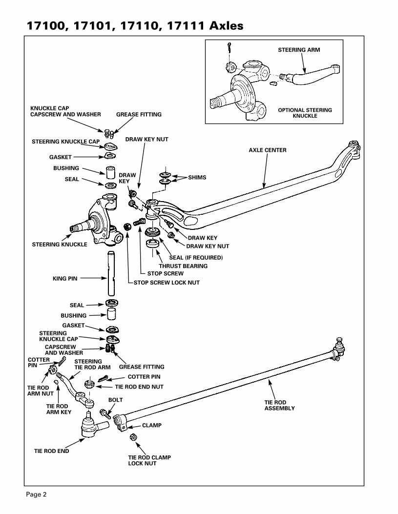
17100, 17101, 17110, 17111 Axles
KING PIN
KNUCKLE CAPCAPSCREW AND WASHER
STEERING KNUCKLE CAP
STEERING KNUCKLE
STEERINGKNUCKLE CAP
STEERING ARM
BUSHING
GREASE FITTING
CAPSCREWAND WASHER
STEERINGTIE ROD ARM
BOLT
CLAMP
TIE RODARM KEY
TIE ROD END
TIE ROD CLAMPLOCK NUT
TIE RODASSEMBLY
GREASE FITTING
GASKET
BUSHING
COTTER PIN
TIE RODARM NUT
DRAW KEY NUT
DRAW KEY
DRAW KEY NUT
SEAL (IF REQUIRED)
THRUST BEARING
STOP SCREW
AXLE CENTER
SEAL SHIMS
STOP SCREW LOCK NUT
SEAL
GASKET
DRAWKEY
COTTER PIN
TIE ROD END NUT
OPTIONAL STEERINGKNUCKLE
Page 2
2270D MM 23 12/6/00 4:46 PM Page 7

Page 3
FH 941, FH 945 and FH 946 Axles
KING PIN
COTTER PIN
STEERING KNUCKLE
THREADEDKNUCKLECAP
STEERING ARM
STEERING ARM NUT
GREASE FITTING
GREASE FITTING
KING PIN CAP
KING PIN CAP
BUSHING
TIE ROD ARM
TIE ROD ARM
FH 946 STANDARD STEERING ARM LOCATION
BOLT
CLAMP
TIE RODARM KEY
TIE ROD END
TIE ROD CLAMPLOCK NUT
TIE RODASSEMBLY
BUSHING
TIE RODARM NUT
DRAW KEY NUT
DRAWKEY
DRAW KEY
DRAW KEY NUT
COTTER PIN
COTTERPIN
TIE ROD END NUT
SEAL (IF REQUIRED)
THRUST BEARING
STOP SCREW
AXLE CENTER
SEALSHIMS
STOP SCREW LOCK NUT
SEAL
STEERING ARM
FH 941, FH 945 AND FH 946
STEERING ARMAND KNUCKLE
2270D MM 23 12/6/00 4:46 PM Page 8

Page 4
Section 1Introduction
DescriptionSix Meritor front non-drive steer axle models areavailable for buses and coaches: 17100, 17101,17110, 17111, FH 941 (not shown), FH 945 and FH 946. Figures 1.1, 1.2 and 1.3.
NOTEModel 17110 and 17111 have identical character-istics as model 17100 and 17101 except that theyhave an I-beam instead of a rectangular beam inthe center. Model FH 941 has I-beam construc-tion.
Figure 1.1
IdentificationThe axle model number identification plate is locatedon the axle center. Use the model number to orderthe correct parts from Meritor. Figures 1.4 and 1.5.
Figure 1.4
Figure 1.5
17101-WX-69
FRONT AXLEIDENTIFICATION NUMBER
IDENTIFICATIONNUMBER
Model Track Lengthinches (mm) inches (mm)
17100 79.66 (2023.4) 95.44 (2424.2)
17101 85.66 (2175.8) 101.44 (2576.6)
17110 79.66 (2023.4) 95.44 (2424.2)
17111 85.66 (2175.8) 101.44 (2576.6)
FH 941 84.94 (2157.5) 101.82 (2586)
FH 945 84.94 (2157.5) 101.82 (2586)
FH 946 84.94 (2157.5) 101.82 (2586)
Figure 1.2
FH 945 L X 3
FRONT AXLEIDENTIFICATION NUMBER
IDENTIFICATIONNUMBER
BRAKEUSAGE
SPECIFICATIONVARIATION
BRAKEUSAGE
SPECIFICATIONVARIATION
Model 17100
Model FH 945
Figure 1.3
Model FH 946
2270D MM 23 12/6/00 4:46 PM Page 9

7. Remove the cotter pin and nut that secures thetie rod arms in the knuckle.
WARNINGUse a brass or leather mallet for assembly and dis-assembly procedures. Do not hit steel parts with asteel hammer. Pieces of a part can break off andcause serious personal injury.
8. Remove the tie rod arms from the knuckle. Ifnecessary tap on the end of the arm with aleather or plastic mallet to separate the armfrom the knuckle. Remove the key from the tierod arm.
9. If necessary, remove the tie rod ends from thetie rod according to the following procedure:Figure 2.2.
a. Mark the position where each tie rod end isinstalled in the tie rod. The position of thetie rod ends determines toe-in.
b. Remove the bolts and nuts from the clampon the tie rod.
c. Remove the tie rod ends from the tie rod.
!
Remove the Tie Rod, Tie RodArms and Tie Rod Ends
WARNINGSTo prevent serious eye injury, always wear
safe eye protection when you perform vehiclemaintenance or service.
Block the wheels to prevent the vehicle frommoving. Support the vehicle with safety stands.Do not work under a vehicle that is supported onlyby jacks. Jacks can slip or fall over and cause seri-ous personal injury.
1. Make sure the vehicle is on a level surface.
2. Place blocks under the wheels not being ser-viced to keep the vehicle from moving.
3. Raise the vehicle so that the wheels you willservice are off the ground. Support the vehiclewith safety stands.
4. Remove the cotter pins and nuts that fasteneach tie rod end to the tie rod arms. Figure 2.1.
5. Disconnect the tie rod assembly from the tierod arm. If necessary, use the removal tool toseparate the tie rod end from the tie rod arm.
6. Disconnect any steering linkage attached to thetie rod arms.
!
!
Page 5
Section 2Removal and Disassembly
Figure 2.1
Figure 2.2
TIE ROD END
TIE ROD END
TUBE SLOT MARKS
TIE ROD ARM
TIE ROD
TIE ROD
2270D MM 23 12/6/00 4:46 PM Page 10
Page 6
Section 2Removal and Disassembly
Figure 2.3
Figure 2.4
ADJUSTINGNUT
ADJUSTINGNUT
JAM NUTLOCKWASHER
WHEELBEARING NUTLOCK WASHER
JAM NUT
FOR MODELS 17100, 17101, 17110, 17111
FOR MODELS FH 941, FH 945, FH 946
PIERCEDLOCK RING
PIERCEDLOCK RINGWHEEL
BEARINGNUT
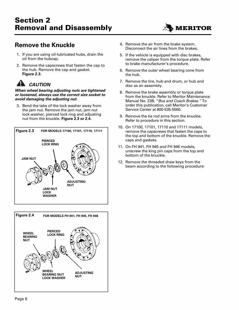
Remove the Knuckle1. If you are using oil-lubricated hubs, drain the
oil from the hubcap.
2. Remove the capscrews that fasten the cap tothe hub. Remove the cap and gasket. Figure 2.3.
CAUTIONWhen wheel bearing adjusting nuts are tightenedor loosened, always use the correct size socket toavoid damaging the adjusting nut.
3. Bend the tabs of the lock washer away fromthe jam nut. Remove the jam nut, jam nut lock washer, pierced lock ring and adjustingnut from the knuckle. Figure 2.3 or 2.4.
!
4. Remove the air from the brake system.Disconnect the air lines from the brakes.
5. If the vehicle is equipped with disc brakes,remove the caliper from the torque plate. Referto brake manufacturer’s procedure.
6. Remove the outer wheel bearing cone from the hub.
7. Remove the tire, hub and drum, or hub anddisc as an assembly.
8. Remove the brake assembly or torque platefrom the knuckle. Refer to Meritor MaintenanceManual No. 23B, “Bus and Coach Brakes.” Toorder this publication, call Meritor’s CustomerService Center at 800-535-5560.
9. Remove the tie rod arms from the knuckle.Refer to procedure in this section.
10. On 17100, 17101, 17110 and 17111 models,remove the capscrews that fasten the caps tothe top and bottom of the knuckle. Remove thecaps and gaskets.
11. On FH 941, FH 945 and FH 946 models,unscrew the king pin caps from the top andbottom of the knuckle.
12. Remove the threaded draw keys from thebeam according to the following procedure:
2270D MM 23 12/7/00 8:07 AM Page 11

13. Use the brass drift and hammer to remove theking pins from the knuckle. If the king pin is diffi-cult to remove, use a hydraulic king pin remover.Refer to Special Tools chart in Section 8.
14. Remove the knuckle from the axle center.Remove the shims, thrust bearing and sealfrom the knuckle. Figure 2.6.
15. If the knuckle bushings are damaged, removethe bushings according to the following proce-dure.
a. Remove and discard the upper and lowerking pin seal. Figure 2.7.
WARNINGUse a brass or leather mallet for assembly and dis-assembly procedures. Do not hit steel parts with asteel hammer. Pieces of a part can break off andcause serious personal injury.
CAUTIONApply force to bottom of nut and end of key. If force is not applied directly, draw key will bedamaged.
a. Loosen the lock nut and move it to the endof the threads. Ensure the top of the lock nutis even with the end of the draw key.
b. Use a brass drift and hammer to hit the endof nut to loosen the draw key. Figure 2.5.
c. Remove the nuts and draw keys from eachside of the beam.
NOTEIf the bushings are not to be replaced, use the fol-lowing procedure to prevent damage to the bush-ings during king pin removal.
• Remove any flaring on the drift that touchesthe king pin.
• Apply tape to 0.0625 inch (1.5 mm) thickness on end of drift.
!
!
Page 7
Section 2Removal and Disassembly
Figure 2.5
LOCK NUT ANDDRAW KEY
Figure 2.6
Figure 2.7
THRUST BEAR-ING AND SEALASSEMBLY
KNUCKLE
KING PINSEAL
SHIMS
2270D MM 23 12/6/00 4:46 PM Page 12
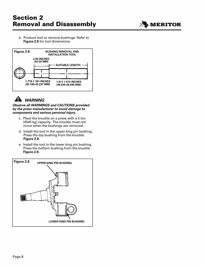
b. Produce tool to remove bushings. Refer toFigure 2.8 for tool dimensions.
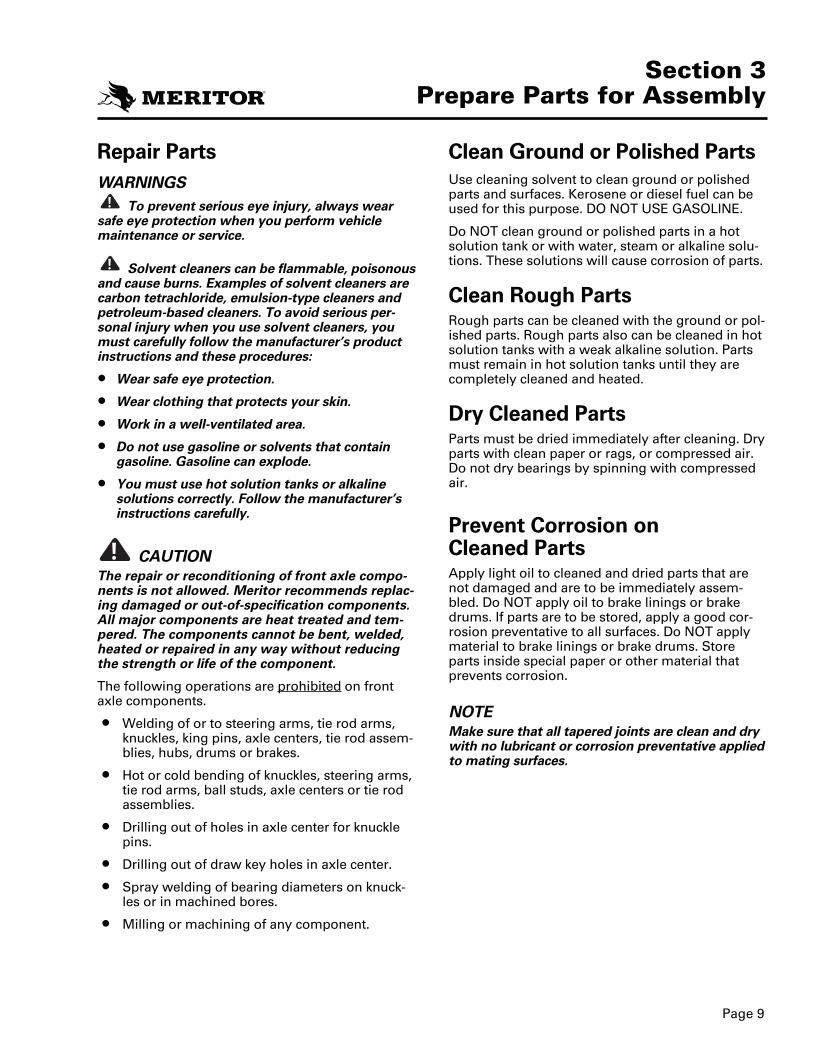
WARNINGObserve all WARNINGS and CAUTIONS providedby the press manufacturer to avoid damage tocomponents and serious personal injury.
c. Place the knuckle on a press with a 5 ton (4545 kg) capacity. The knuckle must notmove when the bushings are removed.
d. Install the tool in the upper king pin bushing.Press the top bushing from the knuckle.Figure 2.9.
e. Install the tool in the lower king pin bushing.Press the bottom bushing from the knuckle.Figure 2.9.
!
Page 8
Section 2Removal and Disassembly
Figure 2.8
Figure 2.9 UPPER KING PIN BUSHING
LOWER KING PIN BUSHING
1.779-1.781 INCHES(45.186-45.237 MM)
1.911-1.913 INCHES(48.539-48.590 MM)
SUITABLE LENGTH
BUSHING REMOVAL AND INSTALLATION TOOL
2.50 INCHES(63.50 MM)
2270D MM 23 12/7/00 8:07 AM Page 13
Page 9
Section 3Prepare Parts for Assembly
Repair PartsWARNINGS
To prevent serious eye injury, always wearsafe eye protection when you perform vehiclemaintenance or service.
Solvent cleaners can be flammable, poisonousand cause burns. Examples of solvent cleaners arecarbon tetrachloride, emulsion-type cleaners andpetroleum-based cleaners. To avoid serious per-sonal injury when you use solvent cleaners, youmust carefully follow the manufacturer’s productinstructions and these procedures:
• Wear safe eye protection.
• Wear clothing that protects your skin.
• Work in a well-ventilated area.
• Do not use gasoline or solvents that containgasoline. Gasoline can explode.
• You must use hot solution tanks or alkalinesolutions correctly. Follow the manufacturer’sinstructions carefully.
CAUTIONThe repair or reconditioning of front axle compo-nents is not allowed. Meritor recommends replac-ing damaged or out-of-specification components.All major components are heat treated and tem-pered. The components cannot be bent, welded,heated or repaired in any way without reducingthe strength or life of the component.
The following operations are prohibited on frontaxle components.
• Welding of or to steering arms, tie rod arms,knuckles, king pins, axle centers, tie rod assem-blies, hubs, drums or brakes.
• Hot or cold bending of knuckles, steering arms,tie rod arms, ball studs, axle centers or tie rodassemblies.
• Drilling out of holes in axle center for knucklepins.
• Drilling out of draw key holes in axle center.
• Spray welding of bearing diameters on knuck-les or in machined bores.
• Milling or machining of any component.
!
!
!
Clean Ground or Polished PartsUse cleaning solvent to clean ground or polishedparts and surfaces. Kerosene or diesel fuel can beused for this purpose. DO NOT USE GASOLINE.
Do NOT clean ground or polished parts in a hotsolution tank or with water, steam or alkaline solu-tions. These solutions will cause corrosion of parts.
Clean Rough PartsRough parts can be cleaned with the ground or pol-ished parts. Rough parts also can be cleaned in hotsolution tanks with a weak alkaline solution. Partsmust remain in hot solution tanks until they arecompletely cleaned and heated.
Dry Cleaned PartsParts must be dried immediately after cleaning. Dryparts with clean paper or rags, or compressed air.Do not dry bearings by spinning with compressedair.
Prevent Corrosion on Cleaned PartsApply light oil to cleaned and dried parts that arenot damaged and are to be immediately assem-bled. Do NOT apply oil to brake linings or brakedrums. If parts are to be stored, apply a good cor-rosion preventative to all surfaces. Do NOT applymaterial to brake linings or brake drums. Storeparts inside special paper or other material thatprevents corrosion.
NOTEMake sure that all tapered joints are clean and drywith no lubricant or corrosion preventative appliedto mating surfaces.
2270D MM 23 12/6/00 4:46 PM Page 14
Inspect the Upper Knuckle Bore1. Remove the old bushing from the knuckle.
2. Measure the upper knuckle bore inside diame-ter in four positions and at two locations. Thetwo locations must be 90 degrees opposedfrom each other. Always use a micrometer anda telescoping gauge when measuring knucklebore inside diameter. Rounding of the top andbottom bore edges is acceptable. Figure 3.2.
3. If the average measurement is more than theknuckle bore maximum diameter specifica-tions in the Axle Wear Limits Specificationstable on page 11, replace the knuckle.
Page 10
Section 3Prepare Parts for Assembly
Inspect Parts
WARNINGTo prevent serious eye injury, always wear safeeye protection when you perform vehicle mainte-nance or service.
Carefully inspect all disassembled parts beforeassembly. Inspect and replace any parts that areworn, cracked or damaged. Check for cracks withdye penetrant, magnetic flux or fluorescent parti-cle testing methods.
Inspect the Fasteners1. Use a torque wrench to verify that all fasteners
are tightened to the specified torque. As soonas the fastener starts to move, record thetorque. Correct if necessary.
2. Replace any worn or damaged fasteners.
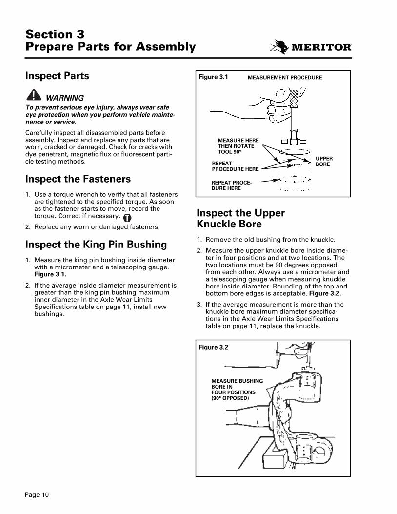
Inspect the King Pin Bushing1. Measure the king pin bushing inside diameter
with a micrometer and a telescoping gauge.Figure 3.1.
2. If the average inside diameter measurement isgreater than the king pin bushing maximuminner diameter in the Axle Wear LimitsSpecifications table on page 11, install newbushings.
!
Figure 3.1
Figure 3.2
MEASURE BUSHINGBORE IN FOUR POSITIONS (90° OPPOSED)
REPEAT PROCEDURE HERE
MEASUREMENT PROCEDURE
UPPERBORE
T
MEASURE HERETHEN ROTATETOOL 90°
REPEAT PROCE-DURE HERE
2270D MM 23 12/6/00 4:46 PM Page 15
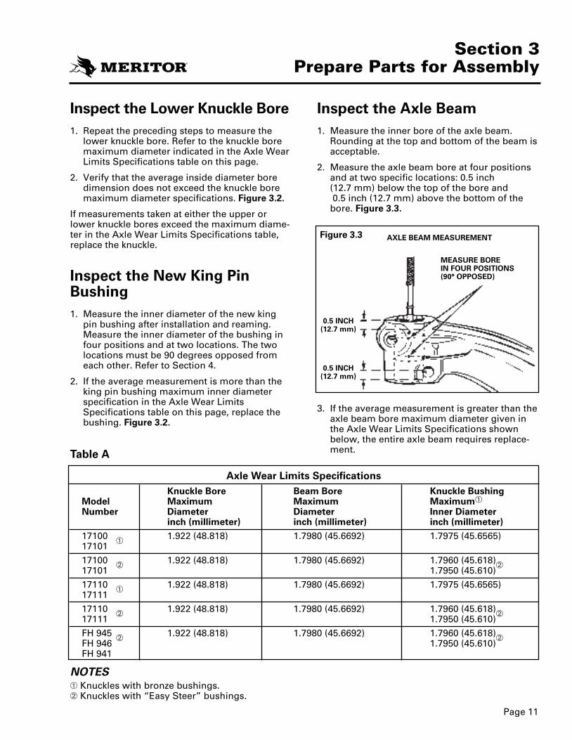
Inspect the Axle Beam1. Measure the inner bore of the axle beam.
Rounding at the top and bottom of the beam isacceptable.
2. Measure the axle beam bore at four positionsand at two specific locations: 0.5 inch (12.7 mm) below the top of the bore and0.5 inch (12.7 mm) above the bottom of thebore. Figure 3.3.
3. If the average measurement is greater than theaxle beam bore maximum diameter given inthe Axle Wear Limits Specifications shownbelow, the entire axle beam requires replace-ment.
Page 11
Section 3Prepare Parts for Assembly
Inspect the Lower Knuckle Bore1. Repeat the preceding steps to measure the
lower knuckle bore. Refer to the knuckle boremaximum diameter indicated in the Axle WearLimits Specifications table on this page.
2. Verify that the average inside diameter boredimension does not exceed the knuckle boremaximum diameter specifications. Figure 3.2.
If measurements taken at either the upper orlower knuckle bores exceed the maximum diame-ter in the Axle Wear Limits Specifications table,replace the knuckle.
Inspect the New King PinBushing1. Measure the inner diameter of the new king
pin bushing after installation and reaming.Measure the inner diameter of the bushing infour positions and at two locations. The twolocations must be 90 degrees opposed fromeach other. Refer to Section 4.
2. If the average measurement is more than theking pin bushing maximum inner diameterspecification in the Axle Wear LimitsSpecifications table on this page, replace thebushing. Figure 3.2.
Figure 3.3
Axle Wear Limits SpecificationsKnuckle Bore Beam Bore Knuckle Bushing
Model Maximum Maximum MaximumretemaiD rennIretemaiDretemaiDrebmuN
inch (millimeter) inch (millimeter) inch (millimeter)
17100 1.922 (48.818) 1.7980 (45.6692) 1.7975 (45.6565)17101
17100 1.922 (48.818) 1.7980 (45.6692) 1.7960 (45.618)17101 1.7950 (45.610)
17110 1.922 (48.818) 1.7980 (45.6692) 1.7975 (45.6565)17111
17110 1.922 (48.818) 1.7980 (45.6692) 1.7960 (45.618)17111 1.7950 (45.610)
FH 945 1.922 (48.818) 1.7980 (45.6692) 1.7960 (45.618)FH 946 1.7950 (45.610)FH 941
NOTESKnuckles with bronze bushings.Knuckles with “Easy Steer” bushings.
AXLE BEAM MEASUREMENT
MEASURE BOREIN FOUR POSITIONS(90° OPPOSED)
0.5 INCH(12.7 mm)
0.5 INCH(12.7 mm)
Table A
2270D MM 23 12/6/00 4:46 PM Page 16

Page 12
Section 3Prepare Parts for Assembly
Figure 3.4WORNRADIUS
WORNSURFACE
4. Inspect the taper on the tie rod arm for wear ordamage. Inspect the hole for the taper in theknuckle. If the hole is worn or damaged, replacethe knuckle and arm. If only the taper on thearm is damaged, replace the arm.
5. If the king pin has worn through the bushingand into the knuckle, replace the knuckle.
NOTEIf any part of the steering linkage is loose, check allthe pivot points. Check the pivot points when thelinkage is lubricated.
6. Make sure all pivot points in the steering linkageare tight.
7. Inspect the thrust bearing and seal for wear ordamage. Replace parts that are worn or dam-aged.
Inspect the Tie Rod and Tie Rod End1. Inspect the tie rod end for wear and damage.
Replace if worn or damaged. Refer to Section 7,“Diagnostics.”
2. If the seal is damaged on tie rod ends equippedwith a grease fitting, replace the seal only.
3. If the seal is damaged on tie rod ends notequipped with a grease fitting, replace completetie rod end.
Inspect the Wheel BearingsInspect the wheel bearings when the knuckle isinspected or repaired.
Remove all lubricant from the bearings, knuckle,hub and hub cap.
Inspect the cup, the cone and the rollers and cageof all bearings. If any of the following conditionsexist, the bearing MUST be replaced.
1. The center of the large diameter end of therollers is worn level or below the outer surface. Figure 3.4.
2. The radius at the large diameter end of therollers is worn to a sharp edge. Figure 3.4.
2270D MM 23 12/6/00 4:46 PM Page 17
Page 13
Section 3Prepare Parts for Assembly
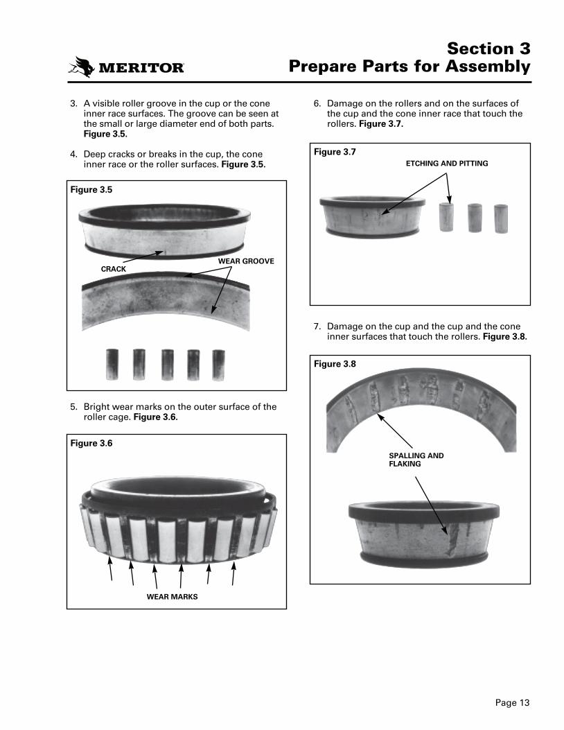
6. Damage on the rollers and on the surfaces ofthe cup and the cone inner race that touch therollers. Figure 3.7.
7. Damage on the cup and the cup and the coneinner surfaces that touch the rollers. Figure 3.8.
3. A visible roller groove in the cup or the coneinner race surfaces. The groove can be seen atthe small or large diameter end of both parts.Figure 3.5.
4. Deep cracks or breaks in the cup, the coneinner race or the roller surfaces. Figure 3.5.
5. Bright wear marks on the outer surface of theroller cage. Figure 3.6.
Figure 3.5
Figure 3.7
Figure 3.8
Figure 3.6
WEAR MARKS
CRACKWEAR GROOVE
ETCHING AND PITTING
SPALLING ANDFLAKING
2270D MM 23 12/6/00 4:46 PM Page 18

Page 14
Section 3Prepare Parts for Assembly
Inspect the Disc BrakeCaliper/Brake Pads• Refer to brake manufacturer’s inspection
instruction.
Inspect the Disc (Rotor)
NOTEThe following information on rotor thicknessapplies only to Meritor Air Disc Brake ModelADB-1560. For brakes from other manufacturers,refer to their instructions.
CAUTIONYou must always replace a damaged disc.
When you inspect the brakes, also inspect bothsides and the outer diameter of the disc. Inspectfor:
• cracks,
• heat checking,
• grooves or score, and
• blue marks or bands.
When you reline the brakes, you must measurethe thickness of the disc.
CracksA crack can extend through a section of the discand can cause the two sides of the crack to sepa-rate. If you find any cracks, always replace thedisc. Figure 3.9.
!
Figure 3.9
Heat CheckingHeat checking produces cracks in the surface ofthe disc. Heat checking can be light or heavy.
• Light Heat Checking
Light heat checking is very fine, tight, smallcracks. Light heat checking is normal. You cancontinue to use a disc with light heat checking.
• Heavy Heat Checking
Heavy heat checking produces surface cracks thathave width and depth. If you find heavy heatchecking, always replace the disc. Figure 3.10.
Figure 3.10
2270D MM 23 12/6/00 4:46 PM Page 19

Page 15
Section 3Prepare Parts for Assembly
Grooves or ScoresCheck both sides of the disc for deep grooves orscores. If the grooves or scores are deep, replacethe disc. If the grooves or scores are not toodeep, you can continue to use the disc. Figure 3.11.
Blue Marks or BandsBlue marks or bands indicate that the disc wasvery hot. If blue marks or bands are present, usethe Diagnostics Guide to find and correct thecause of the problem. Figure 3.12.
Measure Thickness of DiscMeasure the thickness of the disc when youreline the brakes. Discs with vents must be atleast 1.626 inches (41.3 mm) thick. If the thicknessof the disc is less than the specification, alwaysreplace the disc. Figure 3.13.
Figure 3.11 Figure 3.13
Figure 3.12
VENTED DISC
1.626 IN. (41.3 mm)MINIMUM THICK-NESS
2270D MM 23 12/6/00 4:46 PM Page 20

4. Use the installation tool shown in Figure 2.9to press the bushing 0.125 inch (3 mm) intothe bore. Release the pressure on press. Makesure the bushing is pressed straight into thebore.Figure 4.1.
5. Press the bushing into the bore until the topof the bushing is even with the top of theknuckle. Make sure there is 0.135-0.165 inch(3.5-4.0 mm) clearance between the bottom ofbushing and the bottom of the top knucklebore. Figure 4.2.
6. Turn the knuckle over so that the bottom ofthe knuckle is toward the top of the press.Make sure bushing bore is straight.
7. Place the bottom bushing in the bore.
8. Use the installation tool to press the bushing 0.125 inch (3 mm) into the bore. Release thepressure on the press. Make sure the bushingis pressed straight into the bore. Figure 4.1.
9. Press the bushing into the bore until the top ofthe bushing is even with the cap surface of theknuckle. Make sure there is 0.135-0.165 inch (3.5-4.0 mm) clearance between the end of thebushing and the top of the bottom knucklebore.
10. Ream the bushings according to the proce-dure on page 18.
Page 16
Section 4Assembly and Installation
Figure 4.2
Figure 4.1
BOTTOMBUSHING
TOPBUSHING
BUSHING
BUSHING
TOOL
UPPER KNUCKLE0.125" (3 mm)DEPTHINSTALLATION
LOWER KNUCKLE0.125" (3 mm)DEPTH INSTALLATION
0.135-0.165 INCH(3.43-4.19 MM)
0.135-0.165 INCH(3.43-4.19 MM)
Install the Knuckle Bushings
WARNINGTo prevent serious eye injury, always wear safeeye protection when you perform vehicle mainte-nance or service.
Install the Bronze SpindleBushings
WARNINGObserve all WARNINGS and CAUTIONS providedby the press manufacturer concerning press oper-ation to avoid serious personal injury and possi-ble damage to components.
NOTEBronze spindle bushings were installed only onpast models of the 17100, 17101, 17110 and 17111axle series. Bronze spindle bushings are not avail-able on current models of this series.
1. Install the top spindle bushing first.
2. Place the spindle in a press with minimumcapacity of 5 tons (4545 kg) so that the bush-ing bores are straight with the top of theknuckle toward the top of press.
3. Place the bushing in the bore.
!
!
2270D MM 23 12/6/00 4:46 PM Page 21
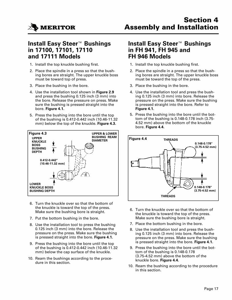
Install Easy Steer™ Bushingsin FH 941, FH 945 and FH 946 Models1. Install the top knuckle bushing first.
2. Place the spindle in a press so that the bush-ing bores are straight. The upper knuckle bossmust be toward the top of the press.
3. Place the bushing in the bore.
4. Use the installation tool and press the bush-ing 0.125 inch (3 mm) into bore. Release thepressure on the press. Make sure the bushingis pressed straight into the bore. Refer toFigure 4.1.
5. Press the bushing into the bore until the bot-tom of the bushing is 0.148-0.178 inch (3.75-4.52 mm) above the bottom of the knucklebore. Figure 4.4.
6. Turn the knuckle over so that the bottom ofthe knuckle is toward the top of the press.Make sure the bushing bore is straight.
7. Place the bottom bushing in the bore.
8. Use the installation tool and press the bush-ing 0.125 inch (3 mm) into bore. Release thepressure on the press. Make sure the bushingis pressed straight into the bore. Figure 4.1.
9. Press the bushing into the bore until the bot-tom of the bushing is 0.148-0.178 (3.75-4.52 mm) above the bottom of theknuckle bore. Figure 4.4.
10. Ream the bushing according to the procedurein this section.
Install Easy Steer™ Bushingsin 17100, 17101, 17110 and 17111 Models1. Install the top knuckle bushing first.
2. Place the spindle in a press so that the bush-ing bores are straight. The upper knuckle bossmust be toward top of press.
3. Place the bushing in the bore.
4. Use the installation tool shown in Figure 2.9and press the bushing 0.125 inch (3 mm) intothe bore. Release the pressure on press. Makesure the bushing is pressed straight into thebore. Figure 4.1.
5. Press the bushing into the bore until the topof the bushing is 0.412-0.442 inch (10.46-11.32mm) below the top of the knuckle. Figure 4.3.
6. Turn the knuckle over so that the bottom ofthe knuckle is toward the top of the press.Make sure the bushing bore is straight.
7. Put the bottom bushing in the bore.
8. Use the installation tool to press the bushing 0.125 inch (3 mm) into the bore. Release thepressure on the press. Make sure the bushingis pressed straight into the bore. Figure 4.1.
9. Press the bushing into the bore until the topof the bushing is 0.412-0.442 inch (10.46-11.32mm) below the cap surface of the knuckle.
10. Ream the bushings according to the proce-dure in this section.
Page 17
Section 4Assembly and Installation
Figure 4.3Figure 4.4UPPER
KNUCKLEBOSSBUSHINGDEPTH
0.412-0.442"(10.46-11.32 mm)
LOWERKNUCKLE BOSSBUSHING DEPTH
UPPER & LOWERBUSHING REAMDIAMETER THREADS
THREADS
0.148-0.178"(3.75-4.52 mm)
0.148-0.178"(3.75-4.52 mm)
2270D MM 23 12/6/00 4:46 PM Page 22
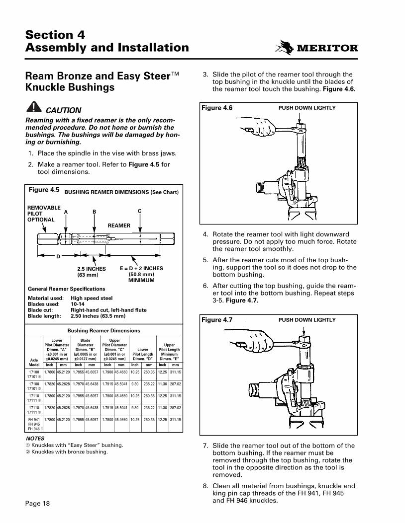
3. Slide the pilot of the reamer tool through thetop bushing in the knuckle until the blades ofthe reamer tool touch the bushing. Figure 4.6.
4. Rotate the reamer tool with light downwardpressure. Do not apply too much force. Rotatethe reamer tool smoothly.
5. After the reamer cuts most of the top bush-ing, support the tool so it does not drop to thebottom bushing.
6. After cutting the top bushing, guide the ream-er tool into the bottom bushing. Repeat steps3-5. Figure 4.7.
7. Slide the reamer tool out of the bottom of thebottom bushing. If the reamer must beremoved through the top bushing, rotate thetool in the opposite direction as the tool isremoved.
8. Clean all material from bushings, knuckle andking pin cap threads of the FH 941, FH 945and FH 946 knuckles.Page 18
Section 4Assembly and Installation
Figure 4.5
Figure 4.6
REMOVABLEPILOTOPTIONAL
REAMER
B C
2.5 INCHES(63 mm)
E = D + 2 INCHES (50.8 mm)MINIMUM
A
PUSH DOWN LIGHTLY
Figure 4.7 PUSH DOWN LIGHTLY
D
BUSHING REAMER DIMENSIONS (See Chart)
General Reamer Specifications
Material used: High speed steelBlades used: 10-14Blade cut: Right-hand cut, left-hand fluteBlade length: 2.50 inches (63.5 mm)
Bushing Reamer Dimensions
Lower Blade UpperreppUretemaiD toliPretemaiDretemaiD toliP
Dimen. “A” Dimen. “B” Dimen. “C” Lower Pilot Length(±0.001 in or (±0.0005 in or (±0.001 in or Pilot Length Minimum
Axle ±0.0245 mm) ±0.0127 mm) ±0.0245 mm) Dimen. “D” Dimen. “E”
Model Inch mm Inch mm Inch mm Inch mm Inch mm
17100 1.7800 45.2120 1.7955 45.6057 1.7900 45.4660 10.25 260.35 12.25 311.1517101
17100 1.7820 45.2628 1.7970 45.6438 1.7915 45.5041 9.30 236.22 11.30 287.0217101
17110 1.7800 45.2120 1.7955 45.6057 1.7900 45.4660 10.25 260.35 12.25 311.1517111
17110 1.7820 45.2628 1.7970 45.6438 1.7915 45.5041 9.30 236.22 11.30 287.0217111
FH 941 1.7800 45.2120 1.7955 45.6057 1.7900 45.4660 10.25 260.35 12.25 311.15FH 945FH 946
NOTESKnuckles with “Easy Steer” bushing.Knuckles with bronze bushing.
Ream Bronze and Easy Steer™Knuckle Bushings
CAUTIONReaming with a fixed reamer is the only recom-mended procedure. Do not hone or burnish thebushings. The bushings will be damaged by hon-ing or burnishing.
1. Place the spindle in the vise with brass jaws.
2. Make a reamer tool. Refer to Figure 4.5 fortool dimensions.
!
2270D MM 23 12/6/00 4:46 PM Page 23

4. Turn the knuckle over in the vise. The jaws ofthe vise must hold the bottom of the knuckle.The top of the knuckle must be toward you.
5. Place the seal in the top of the bottom knuck-le bore. Make sure the lip of the seal is awayfrom the bore.
6. Repeat step 3 of this procedure.
Install the Knuckle1. Clean the knuckle bores and axle center.
2. Place the knuckle on the axle center.
NOTESome newer thrust bearings have the seal inte-grated with the bearing assembly. Figure 4.9.
The one-piece thrust bearing with an integratedgrease seal is completely interchangeable withthe two-piece design. It has a specified top andbottom orientation:
• The surface with the inner diameter sealmust be on top.
• The surface with the outer diameter sealmust be on the bottom. Figure 4.9.
Page 19
Install the Inner Knuckle Bushing Seal1. Place the knuckle in vise with brass jaws so
that the jaws of the vise hold the top of theknuckle. Bottom of the knuckle must betoward you.
2. Place the seal in the bottom of the top knucklebore. Make sure the lip of the seal is awayfrom the bore. Figure 4.8.
WARNINGUse a brass or leather mallet for assembly anddisassembly procedures. Do not hit steel partswith a steel hammer. Pieces of a part can breakoff and cause serious personal injury.
3. Use a brass drift, hammer and correct size dri-ver or socket to install the seal.
• On knuckles with bronze bushings, installthe seal until the bottom of the seal touch-es the bushing.
• On knuckles with Easy-Steer™ bushings,install the seal until the top of the seal iseven with the machined surface of theknuckle. Figure 4.8.
• Both bushing types should press the sealuntil the seal is flush or slightly below themachined yoke face.
!
Figure 4.8
BRONZE DRIFT
KNUCKLE BORE
MACHINED SURFACE
BUSHING
TOP
TOP
BOTTOM
INTEGRATEDGREASE SEAL(RUBBER LIP)
INNERDIAMETERSEAL
Section 4Assembly and Installation
Figure 4.9
2270D MM 23 12/6/00 4:46 PM Page 24
Page 20
Section 4Assembly and Installation
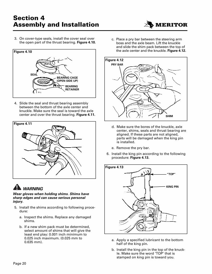
c. Place a pry bar between the steering armboss and the axle beam. Lift the knuckleand slide the shim pack between the top ofthe axle center and the knuckle. Figure 4.12.
d. Make sure the bores of the knuckle, axlecenter, shims, seals and thrust bearing arealigned. If these parts are not aligned,parts will be damaged when the king pinis installed.
e. Remove the pry bar.
6. Install the king pin according to the followingprocedure: Figure 4.13.
a. Apply a specified lubricant to the bottomhalf of the king pin.
b. Install the king pin in the top of the knuck-le. Make sure the word ‘TOP’ that isstamped on king pin is toward you.
3. On cover-type seals, install the cover seal overthe open part of the thrust bearing. Figure 4.10.
4. Slide the seal and thrust bearing assemblybetween the bottom of the axle center andknuckle. Make sure the seal is toward the axlecenter and over the thrust bearing. Figure 4.11.
WARNINGWear gloves when holding shims. Shims havesharp edges and can cause serious personalinjury.
5. Install the shims according to following proce-dure:
a. Inspect the shims. Replace any damagedshims.
b. If a new shim pack must be determined,select amount of shims that will give theleast end play: 0.001 inch minimum to0.025 inch maximum. (0.025 mm to 0.635 mm).
!
Figure 4.12
Figure 4.13
Figure 4.10
Figure 4.11
SEAL
PRY BAR
SHIM
“TOP”
KING PIN
BEARING CAGE(OPEN SIDE UP)
BEARINGRETAINER
2270D MM 23 12/6/00 4:47 PM Page 25
Section 4Assembly and Installation
Page 21
c. Rotate the king pin so that the draw keyslots in the pin are aligned with the holes inthe axle center.
CAUTIONDo not force the pin through the top bushing.Shims will be damaged.
d. Push the king pin through the top bushing,bushing seal and shim pack. If the king pinis difficult to install, make sure all the partsare aligned.
e. After the king pin is through the shim pack,push the king pin into bottom bushing. Ifnecessary, use a brass hammer to drive theking pin into the bushing. Make sure theaxle center, spindle and thrust bearing andbushing seal are aligned.
f. Make sure the draw key slots in the pin arealigned with the holes in the axle center.
NOTEDo not drive the draw keys into the knuckle untilafter the end play is checked and adjusted.
7. Install the top draw key in front of the axlecenter. Install the bottom draw key in back ofthe axle center. Make sure the key goesthrough the slot in the pin. Lightly tap thedraw keys into the axle center. Figure 4.14.
8. Check end play of knuckle according to follow-ing procedure.
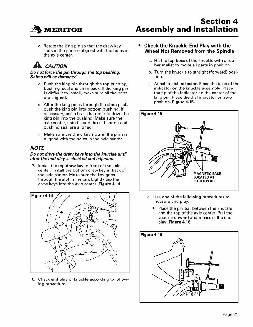
• Check the Knuckle End Play with the
!
Wheel Not Removed from the Spindle
a. Hit the top boss of the knuckle with a rub-ber mallet to move all parts in position.
b. Turn the knuckle to straight (forward) posi-tion.
c. Attach a dial indicator. Place the base of theindicator on the knuckle assembly. Placethe tip of the indicator on the center of theking pin. Place the dial indicator on zeroposition. Figure 4.15.
d. Use one of the following procedures tomeasure end play:
• Place the pry bar between the knuckleand the top of the axle center. Pull theknuckle upward and measure the endplay. Figure 4.16.
Figure 4.15
Figure 4.14
Figure 4.16
MAGNETIC BASELOCATED ATEITHER PLACE
2270DMM23 12/6/004:47PM Page 26

• Check the Knuckle End Play with theWheel Installed on the Spindle
a. Install a dial indicator. Make sure the base ofindicator is on the axle center. Make surethe tip of the indicator is on the center of theknuckle cap. The tip of the indicator can alsobe put on the knuckle. Figure 4.18.
b. Use a lever to lift the knuckle to measurethe end play.
c. End play should measure 0.001-0.025 inch (0.025-0.635 mm) on both knuckles.
• If knuckle is binding or zero end play ismeasured, remove shims from the shim pack.
• If more than 0.025 inch (0.635 mm) endplay is measured, add shims to theshim pack.
WARNINGIf a hydraulic jack is used to measure end play,use safety stands to support the axle. If safetystands are not used, the axle can fall and causeserious personal injury.
• Place a block of wood and hydraulic jackunder the bottom of the knuckle. Raisethe knuckle until the pointer on the dialindicator stops. Figure 4.17.
e. Repeat steps C and D with the axle in fullright turn and full left turn positions.
f. End play must measure 0.001-0.025 inch (0.025-0.635 mm) in all axle positions.
If the knuckle binds or zero end play ismeasured, remove the shims from theshim pack.
If more than 0.025 inch (0.635 mm) endplay is measured, add shims to the shim pack.
!
Page 22
Section 4Assembly and Installation
Figure 4.18
Figure 4.17
WOOD BLOCK
2270D MM 23 12/6/00 4:47 PM Page 27

CAUTIONMake sure the draw key is installed completelyand the locknut is tightened to the specifiedtorque. If the draw key is not installed correctly,the king pin and the axle center will be damaged.
9. Install the lock nut on the threaded draw keysand tighten to 30-45 lb-ft (41-54 N•m). Figure 4.19.
10. For 17100, 17101, 17110 and 17111 axles,install new gaskets and caps on top and bot-tom of knuckle. Install capscrews and washersand tighten to 20-30 lb-ft (28-40 N•m). Figure4.20.
For FH 941, FH 945 and FH 946 axles applysealant 360° around the first thread of theking pin cap and install the top and bottomthreaded king pin caps. Tighten to 100-120 lb-ft (135-160 N•m) Figure 4.20.
!
Section 4Assembly and Installation
Page 23
Figure 4.20
THREADEDKING PINCAP
FH 941, FH 945 &
FH 946 AXLES
T
T
Figure 4.19
T
30-45 LB-FT(41-61 N•m)
CAP
GASKET
11. Connect the tie rod arm to the knuckle. Seeprocedure in this section.
12. Install the brake assembly or torque plate onthe knuckle. Refer to Meritor MaintenanceManual No. 23B, “Bus and Coach Brakes.” Toorder this publication, call Meritor’s CustomerService Center at 800-535-5560.
13. For grease-lubed wheel ends, lubricate thewheel bearings. Refer to Section 6,Lubrication.
14. Install the hub, drum, wheel and tire assem-bly on the knuckle.
15. Install the outer wheel bearing cone in thehub.
16. Adjust the wheel bearings. Refer to Section 5,Adjustments.
17. Install the hub cap and gasket on the knuckle.Install the capscrews and tighten to 20-30 lb-ft(27-41 N•m). Tighten plastic hubcaps to 15-18 lb-ft (20-24 N•m).
18. For oil-lubricated wheel ends, provide theproper lubricant level. Refer to Section 6,Lubrication.
19. Lower the vehicle to the ground. Check brakeoperation.
20. Check and adjust toe-in. Refer to Section 5,Adjustments.
2270D MM 23 12/6/00 4:47 PM Page 28
Section 4Assembly and Installation
Page 24
T
T
T
T
T
T
Figure 4.21
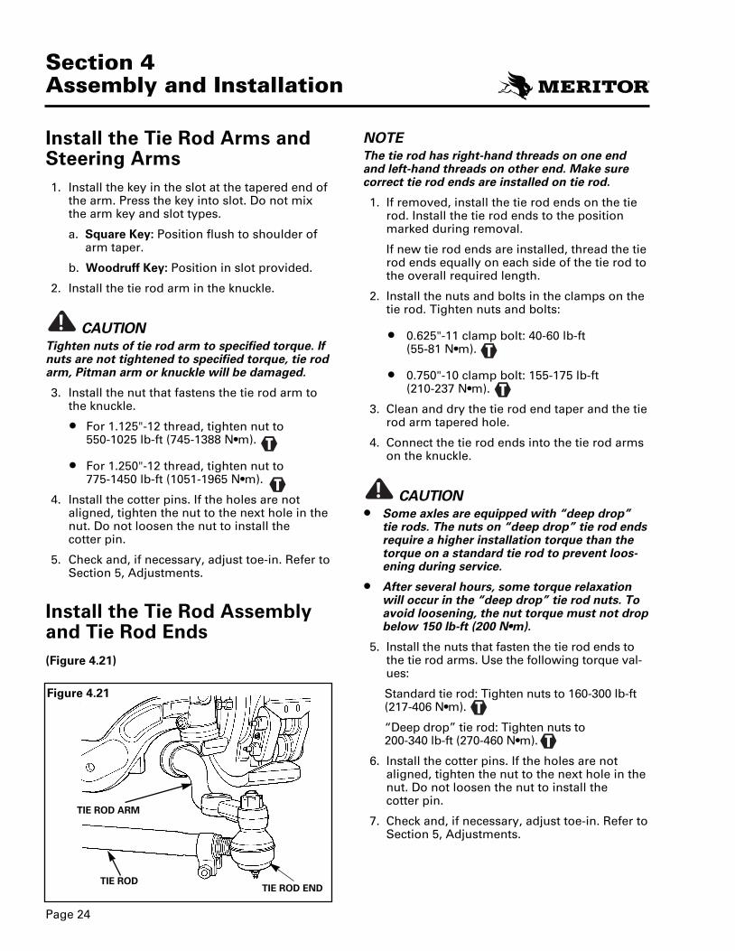
TIE ROD END
TIE ROD ARM
TIE ROD
Install the Tie Rod Arms andSteering Arms1. Install the key in the slot at the tapered end of
the arm. Press the key into slot. Do not mixthe arm key and slot types.
a. Square Key: Position flush to shoulder ofarm taper.
b. Woodruff Key: Position in slot provided.
2. Install the tie rod arm in the knuckle.
CAUTIONTighten nuts of tie rod arm to specified torque. Ifnuts are not tightened to specified torque, tie rodarm, Pitman arm or knuckle will be damaged.
3. Install the nut that fastens the tie rod arm tothe knuckle.
• For 1.125"-12 thread, tighten nut to 550-1025 lb-ft (745-1388 N•m).
• For 1.250"-12 thread, tighten nut to 775-1450 lb-ft (1051-1965 N•m).
4. Install the cotter pins. If the holes are notaligned, tighten the nut to the next hole in thenut. Do not loosen the nut to install the cotter pin.
5. Check and, if necessary, adjust toe-in. Refer toSection 5, Adjustments.
Install the Tie Rod Assemblyand Tie Rod Ends(Figure 4.21)
!
NOTEThe tie rod has right-hand threads on one endand left-hand threads on other end. Make surecorrect tie rod ends are installed on tie rod.
1. If removed, install the tie rod ends on the tierod. Install the tie rod ends to the positionmarked during removal.
If new tie rod ends are installed, thread the tierod ends equally on each side of the tie rod tothe overall required length.
2. Install the nuts and bolts in the clamps on thetie rod. Tighten nuts and bolts:
• 0.625"-11 clamp bolt: 40-60 lb-ft (55-81 N•m).
• 0.750"-10 clamp bolt: 155-175 lb-ft (210-237 N•m).
3. Clean and dry the tie rod end taper and the tierod arm tapered hole.
4. Connect the tie rod ends into the tie rod armson the knuckle.
CAUTION• Some axles are equipped with “deep drop”
tie rods. The nuts on “deep drop” tie rod endsrequire a higher installation torque than thetorque on a standard tie rod to prevent loos-ening during service.
• After several hours, some torque relaxationwill occur in the “deep drop” tie rod nuts. Toavoid loosening, the nut torque must not dropbelow 150 lb-ft (200 N•m).
5. Install the nuts that fasten the tie rod ends tothe tie rod arms. Use the following torque val-ues:
Standard tie rod: Tighten nuts to 160-300 lb-ft(217-406 N•m).
“Deep drop” tie rod: Tighten nuts to 200-340 lb-ft (270-460 N•m).
6. Install the cotter pins. If the holes are notaligned, tighten the nut to the next hole in thenut. Do not loosen the nut to install the cotter pin.
7. Check and, if necessary, adjust toe-in. Refer toSection 5, Adjustments.
!
2270D MM 23 12/6/00 4:47 PM Page 29
Check and Adjust the WheelBearings
WARNINGSTo prevent serious eye injury, always wear
safe eye protection when you perform vehiclemaintenance or service.
Block the wheels to prevent the vehicle frommoving. Support the vehicle with safety stands.Do not work under a vehicle supported only byjacks. Jacks can slip or fall over. Serious personalinjury can result.
1. Make sure the vehicle is on a level surface.
2. Place blocks under the wheels not being ser-viced to keep the vehicle from moving.
3. Raise the vehicle so that the wheels to be ser-viced are off the ground. Support the vehiclewith safety stands.
NOTEIf using oil lube hubs, drain oil from the hubcap.
4. Remove the wheel and tire assembly from thehub.
5. Remove the capscrews that fasten the cap tothe hub. Remove the gasket and cap.
6. If the drum is retained, make sure that it isfirmly attached to the hub by the wheel nuts.
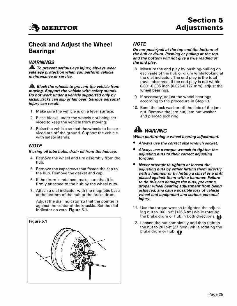
7. Attach a dial indicator with the magnetic baseat the bottom of the hub or the brake drum.
Adjust the dial indicator so that the pointer isagainst the center of the knuckle. Set the dialindicator on zero. Figure 5.1.
!
!
Page 25
Section 5Adjustments
Figure 5.1
T
T
NOTEDo not push/pull at the top and the bottom ofthe hub or drum. Pushing or pulling at the topand the bottom will not give a true reading ofthe end play.
8. Measure the end play by pushing/pulling oneach side of the hub or drum while looking atthe dial indicator. The end play is the totaltravel observed. If the end play is not within0.001-0.005 inch (0.025-0.127 mm), adjust thewheel bearings.
9. If necessary, adjust the wheel bearingsaccording to the procedure in Step 13.
10. Bend the lock washer off the flats of the jamnut. Remove the jam nut, jam nut washerand pierced lock ring.
WARNINGWhen performing a wheel bearing adjustment:
• Always use the correct size wrench socket.
• Always use a torque wrench to tighten theadjusting nuts to their correct adjustingtorques.
• Never attempt to tighten or loosen theadjusting nuts by either hitting them directlywith a hammer or by hitting a chisel or a driftplaced against them with a hammer. Failureto do this can damage the nuts, prevent aproper wheel bearing adjustment from beingachieved, and cause possible loss of vehiclewheel-end equipment and serious personalinjury.
11. Use the torque wrench to tighten the adjust-ing nut to 100 lb-ft (136 N•m) while rotatingthe brake drum or hub in both directions.
12. Loosen the nut completely and then tightenthe nut to 20 lb-ft (27 N•m) while rotating thebrake drum or hub.
!
2270D MM 23 12/6/00 4:47 PM Page 30

13. Adjust the wheel bearings according to thefollowing procedure. Figure 5.2.
a. Back off the adjusting nut 1/3 turn.
b. Install the pierced lock ring, lock washerand jam nut.
c. Tighten a 1-1/8 - 2-5/8 inch threaded jamnut to 200-300 lb-ft (271-407 N•m).
d. Measure the wheel end play to make sureend play is 0.001-0.005 inch (0.025-0.127mm) or Steps “a”-“c” must be repeated. If end play exceeds 0.005 inch (0.127 mm),reduce the amount the adjusting nut isbacked off in Step “a” to 1/4 turn.
e. When the proper end play is achieved, lockthe jam nut in place by bending the edge ofthe jam nut lock washer over one flat of thejam nut.
14. Measure the end play by pushing/pulling onthe horizontal axis of the hub or drum whilelooking at the dial indicator. The end play isthe total travel observed. If the end play is notwithin specifications, adjust the wheel bear-ings.
15. Install the gasket and cap on the hub. Installcapscrews and tighten to 20-30 lb-ft (27-41 N•m). Tighten plastic hub capscrews to 15-18 lb-ft (20-24 N•m).
16. Install the tire and wheel assembly.
17. Lower the vehicle to ground. Check the brakeoperation.
18. Refill the oil lube hub reservoir. Refer toSection 6, Lubrication.
19. Tighten Zytel filler plug to 15-25 lb-in (1.7-2.8 N•m).
Page 26
Section 5Adjustments
T
T
Figure 5.2
JAM NUT
PIERCED LOCKRING
ADJUSTING NUT17100, 17101, 17110, 17111
JAM NUTLOCK WASHER ADJUSTING NUT
FH 945, FH 946
Adjust the Steering StopThe steering stop adjustment controls the maxi-mum turn angle of the vehicle.
CAUTIONIf the stop bolt is missing, bent or broken, thesystem requires adjustment. Refer to“Mechanical Stop” in this section.
NOTE• If the steering system is out of adjustment,
inspect the steering arm and tie rod arms fordamage. Use a magnetic particle or liquid dyepenetrate inspection procedure to inspect thesteering arm. Pay particular attention to thebend, the taper and the area near the ballstud. Refer to the vehicle manufacturer’s man-ual for additional inspection procedures.
• Do not increase specified maximum turn angleof vehicle. If the angle is increased, the steer-ing arm, tie rod and tie rod ends will be dam-aged.
• Adjust the maximum turn angle only if themanufacturer of the vehicle specifies adjust-ment. See specifications of the vehicle manu-facturer for maximum turn angle.
• Meritor does not recommend any powersteering system that does not have mechani-cal stops or pressure relief before the maxi-mum turn angle is obtained.
CAUTIONIn power steering systems, the hydraulic pres-sure should relieve or “drop off” at the end of thesteering stroke (with 0.125 inch or 3 mm mini-mum clearance at the stop bolt). If the pressuredoes not relieve, the components of the frontaxle will be damaged.
!
!
2270D MM 23 12/6/00 4:47 PM Page 31

Page 27
Section 5Adjustments
NOTEFor power steering systems, the stop bolt mustNOT touch the beam. The stop bolt must alwayshave a minimum clearance of 0.125 inch (3 mm)as shown in Figure 5.3.
NOTEFor manual steering systems, Meritor recommends a stop bolt clearance of 0.125 inch (3 mm). Stop bolt contact is acceptable if noother stops are used for the maximum turn angleof the steering knuckle. Figure 5.3.
1. Place a 0.125 inch (3 mm) spacer between thestop bolt and the boss on the axle beam.
2. Turn the steering wheel until the boss on theaxle beam touches the spacer in front of thestop bolt. Measure the turn angle. Figure 5.3.
3. If the maximum turn angle does not meetvehicle manufacturer’s specifications, correctthe maximum angle. In a power steering sys-tem, adjust the pressure relief. In a manualsteering system, follow guidelines and specifi-cations from the vehicle manufacturer.
4. When the maximum turn angle is correct:
a. Loosen the stop bolt jam nut. Figure 5.3.
b. Insert a 0.125 inch (3 mm) spacer andadjust the stop bolt.
c. Tighten the jam nut to 65-85 lb-ft (68-101 N•m).
Adjust the Pressure Relief inthe Power Steering System(Setting Maximum Turn Angle)The pressure relief in the power steering systemstops or reduces forces applied to the axle whenthe wheel is moved in the full turn position.
Check the pressure relief if the steering arm isdamaged or the power steering gear is serviced.
Two types of systems are used to adjust the pres-sure relief.
• Mechanical stop on the Pitman Arm or in theassist cylinder.
• Hydraulic pressure relief in the power steeringgear.
Figure 5.3
T
Two-piece steering stop bolt
STOP BOLT
JAM NUT
0.125" (3 MM)SPACER
AXLEBEAM
STOPSCREWBOSS
2-PIECESTOP BOLTASSEMBLY
MAXIMUMTURNANGLE
2270D MM 23 12/6/00 4:47 PM Page 32
Page 28
Section 5Adjustments
Mechanical StopUse the mechanical stop in the steering system toadjust the pressure relief. Do not use the stopbolt on the knuckle alone to adjust the poppetvalve pressure relief.
NOTERefer to the specified procedures from the vehi-cle manufacturer.
CAUTIONUse a pressure gauge to verify that the pressuredrops from the maximum system delivery pres-sure to a maximum of 700-1000 psi (48.3-69.0 bar) BEFORE the full turning angle is achieved.
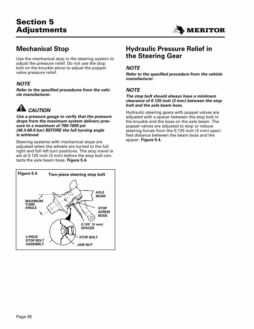
Steering systems with mechanical stops areadjusted when the wheels are turned to the fullright and full left turn positions. The stop travel isset at 0.125 inch (3 mm) before the stop bolt con-tacts the axle beam boss. Figure 5.4.
!
Hydraulic Pressure Relief inthe Steering Gear
NOTERefer to the specified procedure from the vehiclemanufacturer.
NOTEThe stop bolt should always have a minimumclearance of 0.125 inch (3 mm) between the stopbolt and the axle beam boss.
Hydraulic steering gears with poppet valves areadjusted with a spacer between the stop bolt inthe knuckle and the boss on the axle beam. Thepoppet valves are adjusted to stop or reducesteering forces from the 0.125 inch (3 mm) speci-fied distance between the beam boss and thespacer. Figure 5.4.
Figure 5.4 Two-piece steering stop bolt
STOP BOLT
JAM NUT
0.125" (3 mm)SPACER
AXLEBEAM
STOPSCREWBOSS
2-PIECESTOP BOLTASSEMBLY
MAXIMUMTURNANGLE
2270D MM 23 12/6/00 4:47 PM Page 33
Page 29
Section 5Adjustments
Adjust Toe-InSpecification:
• Unloaded: 1/16" ± 1/32" (1.587 mm ± 0.0312mm)
• Loaded: 1/32" ± 1/32" (0.794 mm ± 0.794 mm)
CAUTIONMost tire wear is caused by incorrect toe settings.Do not change camber or caster settings to cor-rect tire wear problems. If the axle assembly isbent to change caster or camber, the strength ofthe axle is reduced and the warranty is voided. Anaxle damaged by bending can cause a vehicleaccident and result in serious personal injury.
WARNINGBlock the wheels to prevent the vehicle frommoving. Support the vehicle with safety stands.Do not work under a vehicle supported only byjacks. Jacks can slip or fall over and cause seriouspersonal injury.
1. Make sure the vehicle is on a level surface.
2. Place blocks under the wheels not being ser-viced to keep the vehicle from moving.
3. Raise the vehicle so that the wheels to be ser-viced are off the ground. Support the vehiclewith safety stands.
4. Use paint or chalk to mark center area of bothfront tires around the complete outer surfaceof the tire.
5. Put the pointers of the trammel bar on themarks of each tire. Rotate tires. Make sure thestraight line is marked on the outer surface of tire.
6. Lower the vehicle to the floor. Move the vehi-cle forward and backward 10 feet (3 meters).
7. Place a trammel bar at back of tires. Align thepointers with the marks on the tires. Raise thepointers so that they are even with the spin-dles. Measure and record the distancebetween pointers.
!
!
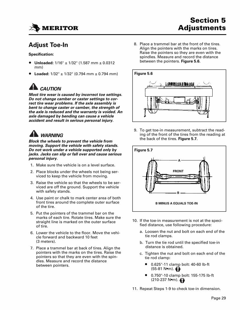
8. Place a trammel bar at the front of the tires.Align the pointers with the marks on tires.Raise the pointers so they are even with thespindles. Measure and record the distancebetween the pointers. Figure 5.6.
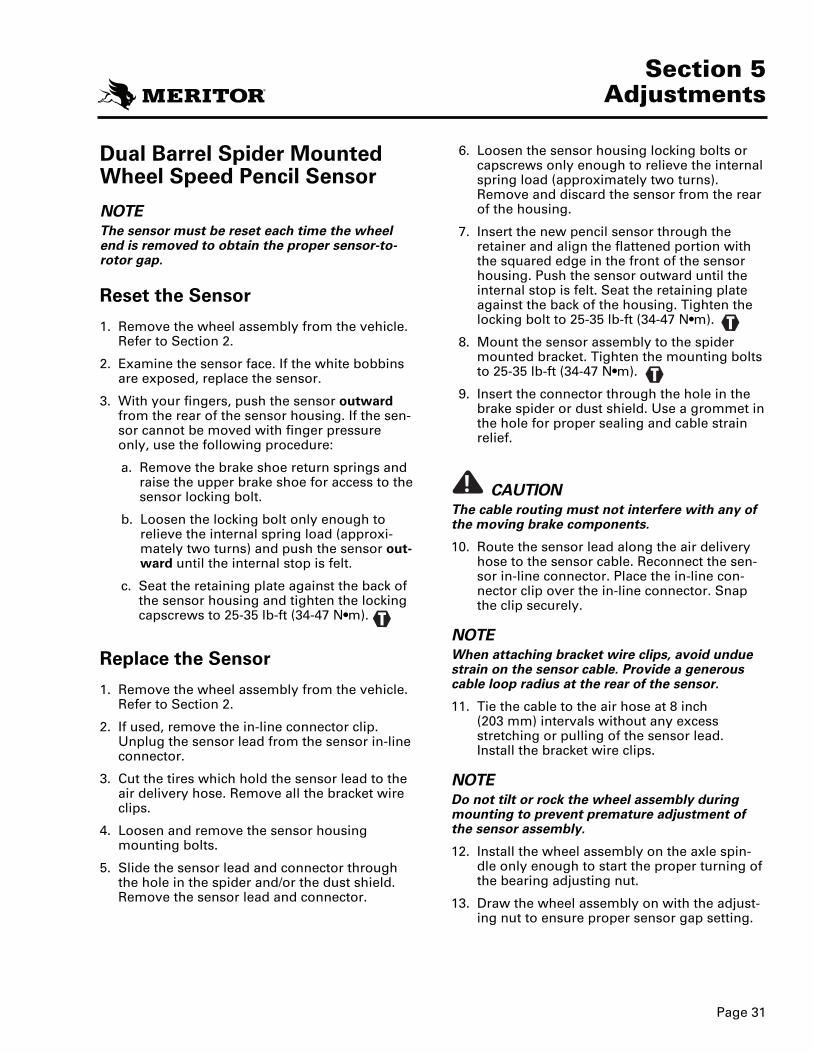
9. To get toe-in measurement, subtract the read-ing of the front of the tires from the reading atthe back of the tires. Figure 5.7.
10. If the toe-in measurement is not at the speci-fied distance, use following procedure:
a. Loosen the nut and bolt on each end of thetie rod clamps.
b. Turn the tie rod until the specified toe-indistance is obtained.
c. Tighten the nut and bolt on each end of thetie rod clamp:
• 0.625"-11 clamp bolt: 40-60 lb-ft (55-81 N•m).
• 0.750"-10 clamp bolt: 155-175 lb-ft (210-237 N•m).
11. Repeat Steps 1-9 to check toe-in dimension.
Figure 5.6
Figure 5.7
FRONT
B MINUS A EQUALS TOE-IN
A
B
T
T
2270D MM 23 12/6/00 4:47 PM Page 34

Page 30
Section 5Adjustments
Camber Angle
WARNINGThe camber angle is not adjustable. Meritor doesnot recommend changing the camber angle orbending the axle beam. If the axle beam is bent tochange the camber angle, the strength of the axleis reduced and the warranty is voided. The axlemay be damaged if bent. An axle damaged bybending may cause a vehicle accident and resultin serious personal injury.
Camber is the angle of the tire in relation to theground. Positive camber occurs when the distancebetween the top of the wheels is greater than thedistance between the bottom of the wheels atground level. A small amount of positive camberis built into the knuckle because camber changeswith load. This results in a zero or neutral camberangle when the vehicle is operated at the normalload. Figure 5.8.
If camber is out of specification by more than 1-1/2degrees, rapid or uneven tire wear will occur.
• Bias ply tires will show excess camber easily.
• Radial tires will not show excess camber easi-ly.
The camber angle is not adjustable. It is machinedinto both the axle beam and the knuckle. If thecamber angle is not at the specified angle, checkthe axle beam and the steering knuckle for dam-age. Service as necessary.
!
Camber Angle Specifications
Axle removed from the vehicle withouthubs and without load:
• Left side (driver’s) and right side (passenger’s):
+1/4 degree nominal
Axle installed on the vehicle without load:
• Left side (driver’s) and right side (passenger’s):
+1/4 degree ± 7/16 degree (–3/16° to 11/16degree) final reading.
Caster AngleCaster is the forward tilt of the king pin centerline when viewed from the side of the vehicle.
The caster angle is the angle from the verticalposition to the center line of the king pin. If thetop of the king pin axis is toward the rear of thevehicle, the caster is positive. A slight positivecaster creates a self-aligning action that helps tostabilize the vehicle after turning and stabilizes itfor driving straight ahead. Figure 5.9.
Too much caster will increase steering effort ormay amplify a shimmy condition.
Adjust caster according to vehicle manufacturer’sprocedure. Refer to vehicle manufacturer’s speci-fications for caster angle.
The coach axle beams have a +3 degree casterangle machined into the beam.
Figure 5.8
Figure 5.9
CAMBER
POSITIVE
CASTER ANGLE
FORWARD
POSITIVECASTER
LOAD
ZEROOR NEUTRAL
2270D MM 23 12/6/00 4:47 PM Page 35
Page 31
Section 5Adjustments
Dual Barrel Spider MountedWheel Speed Pencil Sensor
NOTEThe sensor must be reset each time the wheelend is removed to obtain the proper sensor-to-rotor gap.
Reset the Sensor
1. Remove the wheel assembly from the vehicle.Refer to Section 2.
2. Examine the sensor face. If the white bobbinsare exposed, replace the sensor.
3. With your fingers, push the sensor outwardfrom the rear of the sensor housing. If the sen-sor cannot be moved with finger pressureonly, use the following procedure:
a. Remove the brake shoe return springs andraise the upper brake shoe for access to thesensor locking bolt.
b. Loosen the locking bolt only enough torelieve the internal spring load (approxi-mately two turns) and push the sensor out-ward until the internal stop is felt.
c. Seat the retaining plate against the back ofthe sensor housing and tighten the lockingcapscrews to 25-35 lb-ft (34-47 N•m).
Replace the Sensor
1. Remove the wheel assembly from the vehicle.Refer to Section 2.
2. If used, remove the in-line connector clip.Unplug the sensor lead from the sensor in-lineconnector.
3. Cut the tires which hold the sensor lead to theair delivery hose. Remove all the bracket wireclips.
4. Loosen and remove the sensor housingmounting bolts.
5. Slide the sensor lead and connector throughthe hole in the spider and/or the dust shield.Remove the sensor lead and connector.
6. Loosen the sensor housing locking bolts orcapscrews only enough to relieve the internalspring load (approximately two turns).Remove and discard the sensor from the rearof the housing.
7. Insert the new pencil sensor through theretainer and align the flattened portion withthe squared edge in the front of the sensorhousing. Push the sensor outward until theinternal stop is felt. Seat the retaining plateagainst the back of the housing. Tighten thelocking bolt to 25-35 lb-ft (34-47 N•m).
8. Mount the sensor assembly to the spidermounted bracket. Tighten the mounting boltsto 25-35 lb-ft (34-47 N•m).
9. Insert the connector through the hole in thebrake spider or dust shield. Use a grommet inthe hole for proper sealing and cable strainrelief.
CAUTIONThe cable routing must not interfere with any ofthe moving brake components.
10. Route the sensor lead along the air deliveryhose to the sensor cable. Reconnect the sen-sor in-line connector. Place the in-line con-nector clip over the in-line connector. Snapthe clip securely.
NOTEWhen attaching bracket wire clips, avoid unduestrain on the sensor cable. Provide a generouscable loop radius at the rear of the sensor.
11. Tie the cable to the air hose at 8 inch (203 mm) intervals without any excessstretching or pulling of the sensor lead.Install the bracket wire clips.
NOTEDo not tilt or rock the wheel assembly duringmounting to prevent premature adjustment ofthe sensor assembly.
12. Install the wheel assembly on the axle spin-dle only enough to start the proper turning ofthe bearing adjusting nut.
13. Draw the wheel assembly on with the adjust-ing nut to ensure proper sensor gap setting.
!
T
T
T
2270D MM 23 12/6/00 4:47 PM Page 36
Page 32
Section 5Adjustments
14. Adjust the wheel bearing to the correct speci-fications. Install the lock ring and jam nut.
15. Check the sensor operation with the ServiceAid Tester for proper wheel speed signals.
Replace the Sensor Housingand/or Bracket
WARNINGBlock the wheels to prevent the vehicle frommoving. Support the vehicle with safety stands.Do not work under a vehicle supported only byjacks. Jacks can slip or fall over. Serious personalinjury can result.
1. Make sure the vehicle is on a level surface.
2. Place blocks under the wheels not being ser-viced to keep the vehicle from moving.
3. Raise the vehicle so that the wheels to be ser-viced are off the ground. Support the vehiclewith safety stands.
4. Remove the wheel (hub, drum and tire). Referto Section 2.
CAUTIONDo not twist the connector. This will damage thepins and sockets.
NOTEIt is not necessary to disconnect the long sensorcable (in-line connector to the computer) or toremove the nylon ties. If only the sensor assem-bly and housing is to be removed (bracket left onbrake spider), proceed to Step 8.
5. If used, remove the in-line connector clip anddisconnect the sensor cable.
6. Cut the nylon ties that hold the sensor cable tothe air delivery hose.
!
!
7. Disassemble the complete sensor assembly,housing and bracket from the brake spider byremoving two bracket-to-brake spider cap-screws and washers. Pull the cable throughthe hole in the spider and/or dust shield.
8. Disassemble the sensor assembly with thehousing from the bracket by removing thetwo housing-to-bracket bolts, nuts and wash-ers.
9. If the sensor bracket is to be replaced, securethe bracket to the brake spider with twohousing-to-bracket bolts, nuts and washers.Tighten to 30-45 lb-ft (41-61 N•m).
NOTETo avoid clearance problems, install the boltsfrom the top and install the nuts and washersfrom the bottom.
10. Assemble the sensor assembly with thehousing to the sensor bracket with two bolts,nuts and washers. Tighten to 30-40 lb-ft (41-54 N•m).
11. Insert the connector of the sensor throughthe hole in the brake spider and/or dustshield. Use a grommet in the hole for propersealing and cable strain relief.
12. Route the sensor lead along the air deliveryhose to the sensor cable and reconnect thesensor in-line connector and, if used, installthe in-line connector clip.
T
T
2270D MM 23 12/6/00 4:47 PM Page 37
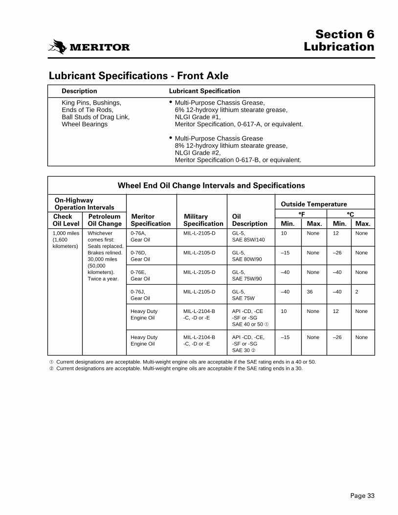
Page 33
Section 6Lubrication
Lubricant Specifications - Front AxlenoitacificepS tnacirbuLnoitpircseD
King Pins, Bushings, • Multi-Purpose Chassis Grease,Ends of Tie Rods, 6% 12-hydroxy lithium stearate grease,Ball Studs of Drag Link, NLGI Grade #1,
.tnelaviuqe ro ,A-716-0 ,noitacificepS rotireMsgniraeB leehW
• Multi-Purpose Chassis Grease8% 12-hydroxy lithium stearate grease,NLGI Grade #2,Meritor Specification 0-617-B, or equivalent.
Wheel End Oil Change Intervals and Specifications
On-HighwayOperation Intervals Outside Temperature
Check Petroleum Meritor Military Oil °F °COil Level Oil Change Specification Specification Description Min. Max. Min. Max.1,000 miles Whichever 0-76A, MIL-L-2105-D GL-5, 10 None 12 None
041/W58 EASliO raeG:tsrif semoc006,1(kilometers) Seals replaced.
Brakes relined. 0-76D, MIL-L-2105-D GL-5, –15 None –26 None09/W08 EASliO raeGselim 000,03
(50,000kilometers). 0-76E, MIL-L-2105-D GL-5, –40 None –40 None
09/W57 EASliO raeG.raey a eciwT
0-76J, MIL-L-2105-D GL-5, –40 36 –40 2W57 EASliO raeG
Heavy Duty MIL-L-2104-B API -CD, -CE 10 None 12 NoneEngine Oil -C, -D or -E -SF or -SG
SAE 40 or 50
Heavy Duty MIL-L-2104-B API -CD, -CE, –15 None –26 NoneEngine Oil -C, -D or -E -SF or -SG
SAE 30
Current designations are acceptable. Multi-weight engine oils are acceptable if the SAE rating ends in a 40 or 50.Current designations are acceptable. Multi-weight engine oils are acceptable if the SAE rating ends in a 30.
2270D MM 23 12/6/00 4:47 PM Page 38

Page 34
Section 6Lubrication
Conventional Front Non-Drive Axle Greasing Intervals and Specifications
edistuOesaerGIGLNrotireMgnisaerGComponent Intervals Grease Specification Grade Classification Temperature
King Pins and 50,000 miles Multi-Purpose O-617-A 1 Lithium Refer to theesaergyxordyH-21esaerGro )mk 000,08(sgnihsuB
s’rerutcafunamro etaraetS,raey a ecnosnoitacificepsmuihtiL2B-716-Orevehcihwno sdutS llaB
eht rofxelpmoC.tsrif semocmrA gnireetSTie Rod Arm temperature Ends and service limits.Drag Link
Applies to ball studs on conventional and Easy Steer axles. For sealed axles, inspect the boot on theball stud every 96,000 miles (154,000 km) for wear and damage. Service as necessary.
2270D MM 23 12/6/00 4:47 PM Page 39

Tie Rod
Lubricate the ends of the tie rod according to thefollowing procedure:
1. Make sure the tires touch the ground.
2. Use a grease gun to lubricate the assembly.Apply the lubricant through grease fittings onassembly. Figure 6.2.
3. Apply the lubricant until new lubricant comesfrom the boot. Figure 6.2.
Grease Lubricated Wheel Bearings
1. Remove the tire and wheel assembly.Remove and disassemble the hub. Refer to“Removing Knuckle” in Section 2.
2. Remove the old lubricant from all parts.Discard the seals. Inspect the wheel bearingsfor wear or damage. Replace worn or dam-aged bearings. Refer to Section 3, “PrepareParts for Assembly.”
3. Force the specified lubricant from the largeend of the cones into the cavities between therollers and cage. Pack the hub between thebearing cups with lubricant to the level of thesmallest diameter of the cups. Figure 6.3.
Page 35
Section 6Lubrication
Figure 6.2
TIE ROD END
LUBRICANTMUST COMEFROM HERE
TIE ROD ARM
TIE ROD
Figure 6.1TOPGREASEFITTING
BOTTOM GREASE FITTING
LUBE MUSTCOME FROMHERE
Lubrication Procedure
King Pins
1. Make sure the tires touch the ground. DONOT RAISE THE VEHICLE.
2. Clean off all grease fittings prior to lubrica-tion.
3. Lubricate the pins through the grease fittingson the top and bottom of the knuckle. Figure 6.1.
4. Apply lubricant until new lubricant comesfrom the thrust bearing seal and the uppershim pack.
2270D MM 23 12/6/00 4:47 PM Page 40

Page 36
Section 6Lubrication
Figure 6.3
Figure 6.4
LUBE
OIL LEVEL
4. Install the inner and outer bearing cones intothe cups in the hubs. The bearing cups mustbe pressed tight against the shoulder in thehubs.
5. Install new wheel seals in the hubs.
6. Install the hub and the wheel and tire assem-bly. Install the outer wheel bearing cone inthe hub. Install the adjusting nut.
7. Adjust the wheel bearings. Refer to “Checkand Adjust the Wheel Bearings” in Section 5.
Oil Lubricated Wheel BearingsCheck the level on the cap. If the oil level is not atthe specified level on the cap, remove the fillplug. Add the specified oil until the oil is at thecorrect level. Figure 6.4.
2270D MM 23 12/6/00 4:47 PM Page 41

Page 37
Section 7Diagnostics
noitcerroCesuaCnoitidnoC
Tires wear out quickly or tireshave uneven tire wear
Vehicle is hard to steer
Ends of the tie rod are worn
Bent or broken tie rod, ball stud, steering arm or cross tube arm
Worn or broken steering ballstud
Worn king pins andbushings
Vibration or shimmy of frontaxle during operation
1. Tires have incorrect air pressure2. Tires out-of-balance3. Incorrect tandem axle alignment4. Incorrect toe-in setting5. Incorrect steering arm geometry6. Excessive wheel end play exists
1. Low pressure in the power steeringsystem
2. Steering gear not assembled correctly
3. Steering linkage needs lubrication4. King pins binding5. Incorrect steering arm geometry6. Caster out-of-adjustment7. Tie rod ends hard to move8. Worn thrust bearing
1. Ends of the tie rod need lubrication2. Severe operating conditions3. Damaged boot on end of tie rod4. Add-on type of power steering cylin-
ders not installed correctly
1. Place specified air pressure in tires.2. Balance or replace tires.3. Align tandem axles.4. Adjust toe-in specified setting.5. Service steering system as necessary.6. Readjust wheel bearings.
1. Repair power steering system.
2. Assemble steering gear correctly.
3. Lubricate steering linkage.4. Replace king pins.5. Service steering system as necessary.6. Adjust caster as necessary.7. Replace tie rod ends.8. Replace thrust bearing.
1. Lubricate ends of tie rod. Make surelubrication schedule is followed.
2. Operate vehicle correctly.3. Replace boot.4. Install power steering cylinders correct-
ly.
The following chart is for diagnosing axle conditions.
1. Too much pressure in the powersteering system
2. Cut-off pressure of the power steer-ing system out-of-adjustment
3. Vehicle not operated correctly
4. Add-on type of power steering sys-tem not installed correctly
1. Drag link fasteners tightened pastspecified torque
2. Lack of lubrication or incorrect lubri-cant
3. Power steering stops out-of-adjust-ment
1. Worn or missing seals and gaskets2. Incorrect lubricant3. Axle not lubricated at scheduled fre-
quency4. Incorrect lubrication procedures5. Lubrication schedule does not match
operating conditions
1. Adjust power steering system to speci-fied pressure.
2. Adjust power steering system to speci-fied pressure.
3. Make sure vehicle is operated correct-ly.
4. Correctly install add-on power steeringsystem.
1. Tighten drag link fasteners to specifiedtorque.
2. Lubricate linkage with specified lubri-cant.
3. Adjust stops to specified dimension.
1. Caster out of adjustment2. Wheels and/or tires out-of-balance3. Worn shock absorbers
1. Adjust caster.2. Balance or replace wheels and/or tires.3. Replace shock absorbers.
1. Replace seals and gaskets.2. Lubricate axle with specified lubricant.3. Lubricate axle at scheduled frequency.
4. Use correct lubrication procedures.5. Change lubrication schedule to match
operating conditions.
2270D MM 23 12/6/00 4:47 PM Page 42
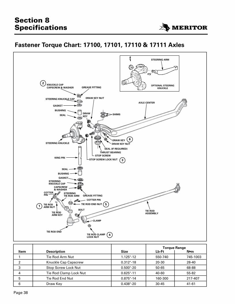
KING PIN
KNUCKLE CAPCAPSCREW & WASHER
STEERING KNUCKLE CAP
STEERING KNUCKLE
STEERINGKNUCKLE CAP
STEERING ARM
BUSHING
GREASE FITTING
CAPSCREW& WASHER
STEERINGTIE ROD ARM
BOLT
CLAMP
TIE RODARM KEY
TIE ROD END TIE ROD CLAMPLOCK NUT
TIE RODASSEMBLY
GREASE FITTING
GASKET
BUSHING
COTTER PIN
TIE RODARM NUT
DRAW KEY NUT
DRAW KEY
DRAW KEY NUT
SEAL (IF REQUIRED)
THRUST BEARINGSTOP SCREW
AXLE CENTER
SEAL SHIMS
STOP SCREW LOCK NUT
SEAL
GASKET
DRAWKEY
COTTER PIN
TIE ROD END NUT
OPTIONAL STEERINGKNUCKLE
Page 38
Section 8Specifications
Torque Rangem•NtF-bLeziSnoitpircseDmetI
3001-547047-05521-"521.1tuN mrA doR eiT1
04-8203-0281-"213.0wercspaC paC elkcunK2
88-8656-0502-"005.0tuN kcoL wercS potS3
28-5506-0411-"526.0tuN kcoL pmalC doR eiT4
704-712003-06141-"578.0tuN dnE doR eiT5
16-1454-0302-"834.0yeK warD6
1
3
2
4
5
6
Fastener Torque Chart: 17100, 17101, 17110 & 17111 Axles
2270D MM 23 12/6/00 4:47 PM Page 43

KING PIN
COTTER PIN
STEERING KNUCKLE
THREADEDKNUCKLECAP
STEERING ARM
STEERING ARM NUT
GREASE FITTING
GREASE FITTING
KING PIN CAP
KING PIN CAP
BUSHING
TIE ROD ARM
TIE ROD ARM
FH 946 STANDARD STEERING ARM LOCATION
BOLT
CLAMP
TIE RODARM KEY
TIE ROD ENDTIE ROD CLAMPLOCK NUT
TIE RODASSEMBLY
BUSHING
TIE RODARM NUT
DRAW KEY NUT
DRAWKEY
DRAW KEY
DRAW KEY NUT
COTTER PIN
COTTERPIN
TIE ROD END NUT
SEAL (IF REQUIRED)
THRUST BEARINGSTOP SCREW
AXLE CENTER
SEALSHIMS
STOP SCREW LOCK NUT
SEAL
Page 39
Section 8Specifications
1
2
6
3
5
4
1A
Fastener Torque Chart: FH 941, FH 945 and FH 946 Axles
Torque Rangem•NtF-bLeziSnoitpircseDmetI
3001-5475201-05521-"521.1tuN mrA doR eiT15691-15010541-57721-"52.1tuN mrA gnireetSA1
061-531021-001"00.2paC elkcunK dedaerhT2
88-8656-0502-"005.0tuN kcoL wercS potS3
4 Tie Rod Clamp Lock Nut 0.625"-11 40-60 55-820.750"-10 155-175 210-237
5 Standard Tie Rod End Nut 0.875"-14 160-300 217-407
5A “Deep Drop” Tie Rod End Nut 0.875"-14 200-340 270-460
16-1454-0302-"5734.0yeK warD6
STANDARDTIE ROD
DEEP DROPTIE ROD
2270D MM 23 12/6/00 4:47 PM Page 44

Page 40
Section 8Specifications
Special ToolsKent-Moore Owatonna Snap-On®
Description Tool Number Tool Number Tool Number
King Pin Remover J 36136 4240 20 Ton: CG430HYB35 Ton: CG730HY
King Pin Bushing Service Kit
King Pin Reamer Kit——A-5734 TPtiK ecivreS cisaB
FH Series171XX Series
NOTESOrder Kent-Moore tools from: Kent-Moore Heavy Duty Division, 29874 Little Mack, Roseville, MI 48066-2298.Order Owatonna tools from OTC Toll and Equipment Division, 655 Eisenhower Drive, Owatonna, MN 55060.See your local Snap-On® dealer.Use Basic Service Kit along with the correct axle series kit.
2270D MM 23 12/6/00 4:47 PM Page 45

Information contained in this publication was in effect at the time the publication was approved for printing and is subject to change without notice or liability. Meritor Commercial Vehicle Systems reserves the right to revise the information presented or discontinue the production of parts described at any time.
Meritor Heavy Vehicle Systems, LLC Meritor do Brasil Ltda. Meritor Commercial Vehicle Systems Saint-Etienne S.A.2135 West Maple Road Av. João Batista, 824 4, Rue Jean ServantonTroy, MI 48084 U.S.A.248-435-1085800-535-5560 (North America only)meritor.com
06097-900 Osasco-SPBRAZIL(55-11) 7084-6510Fax: (55-11) 7084-6600
Boite Postale 65642042 Saint Etienne Cedex 1FRANCE(33) 477.92.88.00 Fax: (33) 477.92.88.93
Maintenance Manual 23Issued 7-98
47865/Meritor
© Copyright 1998 Meritor, Inc All Rights Reserved Printed in the U.S.A.
2270DMM23 12/6/004:46PM Page 1