From Signals to Packetssrini/15-441/F11/lectures/06-datalink.pdf · •8B/10B: Fiber Channel and...
18
06-datalink.ppt, 15-441, Fall 2011 1 15-441 © CMU 2011 15-441 Computer Networking Lecture 6 - Coding and Error Control 15-441 © CMU 2011 2 From Signals to Packets Analog Signal “Digital” Signal Bit Stream 0 0 1 0 1 1 1 0 0 0 1 Packets 0100010101011100101010101011101110000001111010101110101010101101011010111001 Header/Body Header/Body Header/Body Receiver Sender Packet Transmission 2 15-441 © CMU 2011 3 Network Delay • Follow up on requirements from last week: "A new transatlantic cable (the first in 10 years) is going to be laid at the cost of $300M. The reason? To shave 6ms off the time to transmit packets from London to New York. The Hibernian Express will reduce the current transmission time — roughly 65 milliseconds — by less than ten percent. However, investors believe the financial community will be lining up to pay premium rates to use the new cable. The article suggests that a one-millisecond advantage could be worth $100M per year to a large hedge fund." — http://slashdot.org, September 13, 2011 @05:11AM 15-441 © CMU 2011 4 Link Layer: Implementation • Implemented in “adapter” • E.g., PCMCIA card, Ethernet card • Typically includes: RAM, DSP chips, host bus interface, and link interface application transport network link physical network link physical M M M M Ht Ht Hn Ht Hn Hl M Ht Hn Hl frame phys. link data link protocol adapter card 4
Transcript of From Signals to Packetssrini/15-441/F11/lectures/06-datalink.pdf · •8B/10B: Fiber Channel and...

06-datalink.ppt, 15-441, Fall 2011 1
15-441 © CMU 2011
15-441 Computer Networking
Lecture 6 - Coding and Error Control
15-441 © CMU 2011 2
From Signals to Packets
Analog Signal
“Digital” Signal
Bit Stream 0 0 1 0 1 1 1 0 0 0 1
Packets 0100010101011100101010101011101110000001111010101110101010101101011010111001
Header/Body Header/Body Header/Body
ReceiverSenderPacket
Transmission
2
15-441 © CMU 2011 3
Network Delay
• Follow up on requirements from last week:"A new transatlantic cable (the first in 10 years) is going to belaid at the cost of $300M. The reason? To shave 6ms off thetime to transmit packets from London to New York. TheHibernian Express will reduce the current transmission time —roughly 65 milliseconds — by less than ten percent. However,investors believe the financial community will be lining up to paypremium rates to use the new cable. The article suggests that aone-millisecond advantage could be worth $100M per year to alarge hedge fund."
— http://slashdot.org, September 13, 2011 @05:11AM
15-441 © CMU 2011 4
Link Layer: Implementation
• Implemented in “adapter”• E.g., PCMCIA card, Ethernet card• Typically includes: RAM, DSP chips, host bus interface, and link
interface
applicationtransportnetwork
linkphysical
networklink
physical
MMMM
Ht
HtHn
HtHnHl MHtHnHl
framephys. link
data linkprotocol
adapter card
4

06-datalink.ppt, 15-441, Fall 2011 2
15-441 © CMU 2011 5
Datalink Functions
• Framing: encapsulating a network layer datagram intoa bit stream.• Add header, mark and detect frame boundaries
• Media access: controlling which frame should be sentover the link next.
• Error control: error detection and correction to dealwith bit errors.• May also include other reliability support, e.g. retransmission
• Flow control: avoid that the sender outruns thereceiver
• Hubbing, bridging: extend the size of the network
5 15-441 © CMU 2011 6
Outline
• Encoding• Digital signal to bits
• Framing• Bit stream to packets
• Packet loss & corruption• Error detection• Flow control• Loss recovery
6
15-441 © CMU 2011 7
How Encode?
• Seems obvious, why take time with this?
V 0
.85
-.85
0 0 0 11 0 1 0 1
7 15-441 © CMU 2011 8
Why Encode?
0 1 0 1 How many more ones?
8

06-datalink.ppt, 15-441, Fall 2011 3
15-441 © CMU 2011 9
Why Do We Need Encoding?
• Keep receiver synchronized with sender.• Create control symbols, in addition to regular data
symbols.• E.g. start or end of frame, escape, ...
• Error detection or error corrections.• Some codes are illegal so receiver can detect certain
classes of errors• Minor errors can be corrected by having multiple adjacent
signals mapped to the same data symbol• Encoding can be done one bit at a time or in multi-bit
blocks, e.g., 4 or 8 bits.• Encoding can be very complex, e.g. wireless.
9 15-441 © CMU 2011 10
Non-Return to Zero (NRZ)
• 1 high signal; 0 low signal• Used by Synchronous Optical Network (SONET)• Long sequences of 1’s or 0’s can cause problems:
• Sensitive to clock skew, i.e. hard to recover clock• DC bias hard to detect – low and high detected by difference
from average voltage
V 0
.85
-.85
0 0 0 11 0 1 0 1
10
15-441 © CMU 2011 11
Clock Recovery
• When to sample voltage?• Synchronized sender and
receiver clocks• Need easily detectible
event at both ends• Signal transitions help
resync sender and receiver• Need frequent transitions to
prevent clock skew• SONET XOR’s bit sequence
to ensure frequenttransitions
11
http://yellowfourier.com/eyedia.html
15-441 © CMU 2011 12
Non-Return to Zero Inverted(NRZI)
• 1 make transition; 0 signal stays the same• Solves the problem for long sequences of 1’s, but
not for 0’s.
V 0
.85
-.85
0 0 0 11 0 1 0 1
12

06-datalink.ppt, 15-441, Fall 2011 4
15-441 © CMU 2011 13
Manchester Encoding
• Used by Ethernet• 0=low to high transition, 1=high to low transition• Transition for every bit simplifies clock recovery• DC balance has good electrical properties• Not very efficient
• Doubles the number of transitions• Circuitry must run twice as fast
V 0
.85
-.85
0 1 1 0
.1µs
13 15-441 © CMU 2011 14
4B/5B Encoding
• Data coded as symbols of 5 line bits 4 databits, so 100 Mbps uses 125 MHz.• Uses less frequency space than Manchester encoding
• Encoding ensures no more than 3 consecutive 0’s• Uses NRZI to encode resulting sequence• 16 data symbols, 8 control symbols
• Data symbols: 4 data bits• Control symbols: idle, begin frame, etc.
• Example: FDDI.
14
15-441 © CMU 2011 15
4B/5B Encoding
00000001001000110100010101100111
1111001001101001010101010010110111001111
Data Code
10001001101010111100110111101111
1001010011101101011111010110111110011101
Data Code
15 15-441 © CMU 2011 16
Other Encodings
• 8B/10B: Fiber Channel and Gigabit Ethernet• 64B/66B: 10 Gbit Ethernet• B8ZS: T1 signaling (bit stuffing)
• Encoding necessary for clocking• Lots of approaches• Rule of thumb:
• Little bandwidth complex encoding• Lots of bandwidth simple encoding
Things to Remember
16

06-datalink.ppt, 15-441, Fall 2011 5
15-441 © CMU 2011 17
From Signals to Packets
Analog Signal
“Digital” Signal
Bit Stream 0 0 1 0 1 1 1 0 0 0 1
Packets 0100010101011100101010101011101110000001111010101110101010101101011010111001
Header/Body Header/Body Header/Body
ReceiverSenderPacket
Transmission
17 15-441 © CMU 2011 18
Outline
• Encoding• Digital signal to bits
• Framing• Bit stream to packets
• Packet loss & corruption• Error detection• Flow control• Loss recovery
18
15-441 © CMU 2011 19
Framing
• How do we differentiate the stream of bits intoframes?
01000101010111001010101010111011100000011110101011101010101011010110101
19 15-441 © CMU 2011 20
Framing
• A link layer function, defining which bits havewhich function.
• Minimal functionality: mark the beginning and endof packets (or frames).
• Some techniques:• out of band delimiters (e.g. FDDI 4B/5B control
symbols)• frame delimiter characters with character stuffing• frame delimiter codes with bit stuffing• synchronous transmission (e.g. SONET)
20

06-datalink.ppt, 15-441, Fall 2011 6
15-441 © CMU 2011 21
Out-of-band: E.g., 802.5
• 802.5/token ring uses 4b/5b• Start delim & end delim are “illegal” codes
Startdelim
Accessctrl
Body checksumFrame
ctrlDestadr
Srcadr
Enddelim
Framestatus
21 15-441 © CMU 2011 22
Delimiter Based
• SYN: sync character• SOH: start of header• STX: start of text• ETX: end of text
• What happens when ETX is in Body?
SYN SYN SOH Header STX Body ETX CRC
22
15-441 © CMU 2011 23
Character and Bit Stuffing
• Mark frames with special character.• What happens when the user sends this character?• Use escape character when controls appear in data:• *abc*def *abc\*def• Very common on serial lines, in editors, etc.
• Mark frames with special bit sequence• must ensure data containing this sequence can be transmitted• example: suppose 11111111 is a special sequence.• transmitter inserts a 0 when this appears in the data:• 11111111 111111101• must stuff a zero any time seven 1s appear:• 11111110 111111100• receiver unstuffs.
23 15-441 © CMU 2011 24
preamble datagram length more stuff
24
Ethernet Framing
• Preamble is 7 bytes of 10101010 (5 MHz squarewave) followed by one byte of 10101011• With Manchester code, 10101 becomes 10 01 10 01 10,
which looks like 1 00 11 00 11 0, which looks like 5 MHzsquare wave
• Allows receivers to recognize start of transmissionafter idle channel

06-datalink.ppt, 15-441, Fall 2011 7
15-441 © CMU 2011 25
Clock-Based Framing
• Used by SONET• Fixed size frames (810 bytes)• Look for start of frame marker that appears every
810 bytes• Will eventually sync up
25 15-441 © CMU 2011 26
How avoid clock skew?
• Special bit sequences sent in first two chars offrame• But no bit stuffing. Hmmm?
• Lots of transitions by xoring with special pattern(and hope for the best)
26
15-441 © CMU 2011 27
Outline
• Encoding• Digital signal to bits
• Framing• Bit stream to packets
• Packet loss & corruption• Error detection• Flow control• Loss recovery
27 15-441 © CMU 2011 28
Error Coding
• Transmission process may introduce errors into amessage.• Single bit errors versus burst errors
• Detection:• Requires a convention that some messages are invalid• Hence requires extra bits• An (n,k) code has codewords of n bits with k data bits and r
= (n-k) redundant check bits• Correction
• Forward error correction: many related code words map tothe same data word
• Detect errors and retry transmission
28

06-datalink.ppt, 15-441, Fall 2011 8
15-441 © CMU 2011 29
Error Detection• EDC= Error Detection and Correction bits (redundancy)• D = Data protected by error checking, may include header fields• Error detection not 100% reliable!
• Protocol may miss some errors, but rarely• Larger EDC field yields better detection and correction
29 15-441 © CMU 2011 30
Parity Checking
Single Bit Parity:Detect single bit errors
30
15-441 © CMU 2011 3131
Internet Checksum
Sender• Treat segment contents
as sequence of 16-bitintegers
• Checksum: addition (1’scomplement sum) ofsegment contents
• Sender puts checksumvalue into checksum fieldin header
Receiver• Compute checksum of
received segment• Check if computed
checksum equals checksumfield value:• NO - error detected• YES - no error detected.
But maybe errorsnonetheless?
• Goal: detect “errors” (e.g., flipped bits) in transmittedsegment
15-441 © CMU 2011 32
Basic Concept:Hamming Distance• Hamming distance of two bit
strings = number of bitpositions in which they differ.
• If the valid words of a codehave minimum Hammingdistance D, then D-1 biterrors can be detected.
• If the valid words of a codehave minimum Hammingdistance D, then [(D-1)/2] biterrors can be corrected.
1 0 1 1 01 1 0 1 0
HD=2
HD=3
32

06-datalink.ppt, 15-441, Fall 2011 9
15-441 © CMU 2011 33
Example 1: Parity
• What is the minimum Hamming distance between tovalid code words using a single parity bit?
• How many bit errors can always be detected withparity?
• If there are more bit errors, how often will they bedetected?
• What is [(D-1)/2] for parity?• How many bit errors can be corrected with parity?
33 15-441 © CMU 2011 34
Examples
• A (4,3) parity code has D=2:• 0001 0010 0100 0111 1000 1011 1101 1110• (last bit is binary sum of previous 3, inverted - “odd parity”)
• A (7,4) code with D=3 (2ED, 1EC):• 0000000 0001101 0010111 0011010• 0100011 0101110 0110100 0111001• 1000110 1001011 1010001 1011100• 1100101 1101000 1110010 1111111
• 1001111 corrects to 1001011• Note the inherent risk in correction; consider a 2-bit
error resulting in 1001011 1111011.• There are formulas to calculate the number of extra
bits that are needed for a certain D.
34
15-441 © CMU 2011 35
Cyclic Redundancy Codes(CRC)• Commonly used codes that have good error
detection properties.• Can catch many error combinations with a small
number of redundant bits• Based on division of polynomials.
• Errors can be viewed as adding terms to the polynomial• Should be unlikely that the division will still work
• Can be implemented very efficiently in hardware.• Examples:
• CRC-32: Ethernet• CRC-8, CRC-10, CRC-32: ATM
35 15-441 © CMU 2011 36
CRC: Basic idea
• Treat bit strings as polynomials:1 0 1 1 1X4+ X2+X1+X0
• Sender and Receiver agree on a divisor polynomialof degree k
• Message of M bits send M+k bits• No errors if M+k is divisible by divisor polynomial• If you pick the right divisor you can:
• Detect all 1 & 2-bit errors• Any odd number of errors• All Burst errors of less than k bits• Some burst errors >= k bits
36

06-datalink.ppt, 15-441, Fall 2011 10
15-441 © CMU 2011 37
Outline
• Encoding• Digital signal to bits
• Framing• Bit stream to packets
• Packet loss & corruption• Error detection• Flow control• Loss recovery
37 15-441 © CMU 2011 38
Link Flow Control andError Recovery• Dealing with receiver overflow: flow control.• Dealing with packet loss and corruption: error control.• Meta-comment: these issues are relevant at many
layers.• Link layer: sender and receiver attached to the same “wire”• End-to-end: transmission control protocol (TCP) - sender
and receiver are the end points of a connection• How can we implement flow control?
• “You may send” (windows, stop-and-wait, etc.)• “Please shut up” (source quench, 802.3x pause frames, etc.)• Where are each of these appropriate?
38
15-441 © CMU 2011 39
A Naïve Protocol
• Sender simply sends to the receiver whenever ithas packets.
• Potential problem: sender can outrun the receiver.• Receiver too slow, buffer overflow, ..
• Not always a problem: receiver might be fastenough.
Sender Receiver
39 15-441 © CMU 2011 40
Adding Flow Control
• Stop and wait flow control: sender waits to sendthe next packet until the previous packet has beenacknowledged by the receiver.• Receiver can pace the receiver
Sender Receiver
40

06-datalink.ppt, 15-441, Fall 2011 11
15-441 © CMU 2011 41
Drawback: Performance
Sender
ReceiverTime
Max Throughput = 1 pktRoundtrip Time
RTT
41 15-441 © CMU 2011 42
Window Flow Control
• Stop and wait flow control results in poor throughputfor long-delay paths: packet size/ roundtrip-time.
• Solution: receiver provides sender with a window thatit can fill with packets.• The window is backed up by buffer space on receiver• Receiver acknowledges the a packet every time a packet is
consumed and a buffer is freed
Sender Receiver
42
15-441 © CMU 2011 43
Bandwidth-Delay Product
Sender
ReceiverTime
Max Throughput = Window SizeRoundtrip Time
RTT
43 15-441 © CMU 2011 44
Error Recovery
• Two forms of error recovery• Error Correcting Codes (ECC)• Automatic Repeat Request (ARQ)
• ECC• Send extra redundant data to help repair losses
• ARQ• Receiver sends acknowledgement (ACK) when it
receives packet• Sender uses ACKs to identify and resend data that was
lost
• Which should we use? Why? When?
44

06-datalink.ppt, 15-441, Fall 2011 12
15-441 © CMU 2011 45
Error Recovery Example:Error Correcting Codes (ECC)
Two Dimensional Bit Parity:Detect and correct single bit errors
0 0
45 15-441 © CMU 2011 4646
Stop and Wait
Time
Packet
ACKTim
eout
• Simplest ARQprotocol
• Send a packet,stop and wait untilacknowledgementarrives
• Will examine ARQissues later insemester
Sender Receiver
15-441 © CMU 2011 4747
Recovering from Error
Packet
ACK
Tim
eout
Packet
Tim
eout
Time
Packet
ACK
Tim
eout
Packet lost
Packet
ACK
Tim
eout
Early timeout
Packet
ACK
Tim
eout
Packet
ACK
Tim
eout
ACK lost
15-441 © CMU 2011 48
How to RecognizeRetransmissions?
• Use sequence numbers• both packets and acks
• Sequence # in packet isfinite How big should itbe?• For stop and wait?
• One bit – won’t send seq #1until received ACK for seq#0
Pkt 0
ACK 0
Pkt 0
ACK 1
Pkt 1ACK 0
48
06-datalink.ppt, 15-441, Fall 2011 13
15-441 © CMU 2011 49
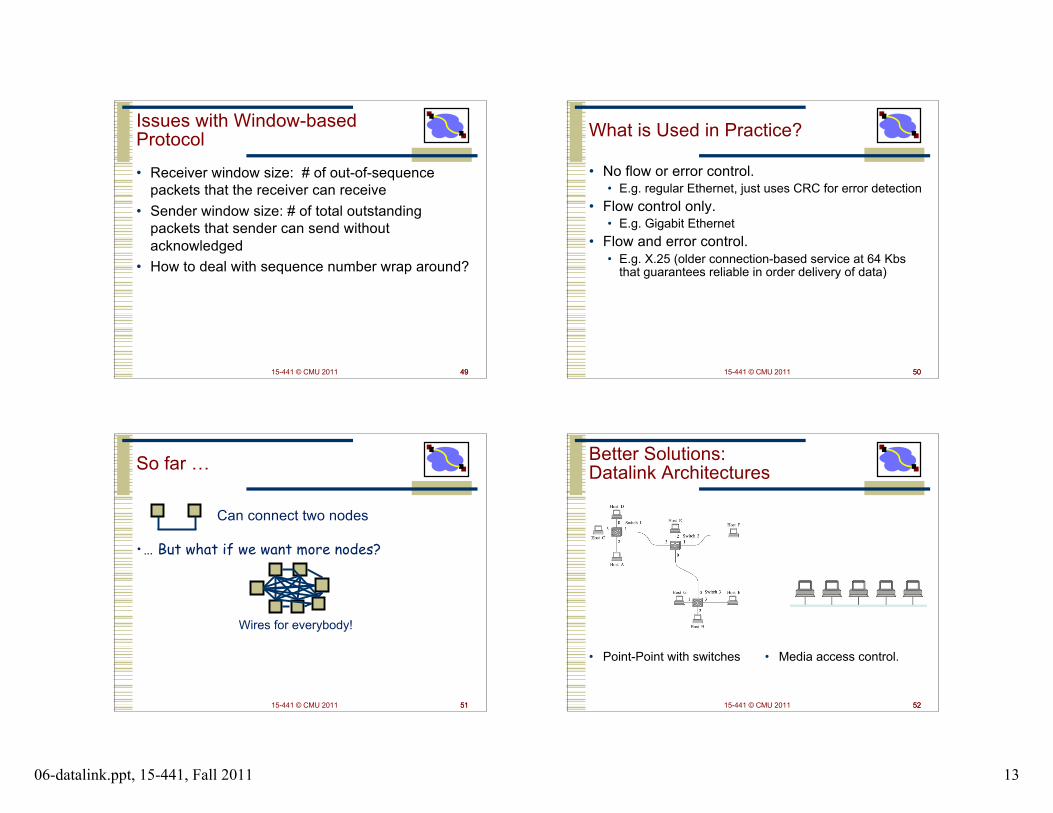
Issues with Window-basedProtocol
• Receiver window size: # of out-of-sequencepackets that the receiver can receive
• Sender window size: # of total outstandingpackets that sender can send withoutacknowledged
• How to deal with sequence number wrap around?
49 15-441 © CMU 2011 50
What is Used in Practice?
• No flow or error control.• E.g. regular Ethernet, just uses CRC for error detection
• Flow control only.• E.g. Gigabit Ethernet
• Flow and error control.• E.g. X.25 (older connection-based service at 64 Kbs
that guarantees reliable in order delivery of data)
50
15-441 © CMU 2011 51
So far …
•… But what if we want more nodes?
Wires for everybody!
Can connect two nodes
51 15-441 © CMU 2011 52
Better Solutions:Datalink Architectures
• Point-Point with switches • Media access control.
52

06-datalink.ppt, 15-441, Fall 2011 14
15-441 © CMU 2011 53
Outline
• Encoding• Digital signal to bits, e.g. NRZ, Manchester• Clock recovery/synchronization
• Framing• Bit stream to packets, e.g. character stuffing, bit stuffing,
synchronous
• Packet loss & corruption• Error detection, e.g. CRC, checksum, parity, Hamming Distance• Flow control, concept of windows• Loss recovery, e.g. error correction, ARQ
53 15-441 © CMU 2011 54
EXTRA SLIDES
54
15-441 © CMU 2011 55
Clock Based Framing: SONET
• SONET is the Synchronous Optical Networkstandard for data transport over optical fiber.
• One of the design goals was to be backwardscompatible with many older telco standards.
• Beside minimal framing functionality, it providesmany other functions:• operation, administration and maintenance (OAM) communications• synchronization• multiplexing of lower rate signals• multiplexing for higher rates
• In other words, really complicated!
55 15-441 © CMU 2011 56
Standardization History
• Process was started by divestiture in 1984.• Multiple telephone companies building their own
infrastructure• SONET concepts originally developed by Bellcore.• First standardized by ANSI T1X1 group for US.• Later by CCITT and developed its own version.• SONET/SDH standards approved in 1988.
56

06-datalink.ppt, 15-441, Fall 2011 15
15-441 © CMU 2011 57
A Word about Data Rates
• Bandwidth of telephone channel is under 4KHz,so when digitizing:
8000 samples/sec * 8 bits = 64Kbits/second• Common data rates supported by telcos in
North America:• Modem: rate improved over the years• T1/DS1: 24 voice channels plus 1 bit per sample (24 * 8 + 1) * 8000 = 1.544 Mbits/second• T3/DS3: 28 T1 channels: 7 * 4 * 1.544 = 44.736 Mbits/second
57 15-441 © CMU 2011 58
Synchronous Data Transfer
• Sender and receiver are always synchronized.• Frame boundaries are recognized based on the clock• No need to continuously look for special bit sequences
• SONET frames contain room for control and data.• Data frame multiplexes bytes from many users• Control provides information on data, management, …
3 colstransportoverhead
87 cols payload capacity
9 rows
58
15-441 © CMU 2011 59
How avoid clock skew?
• Special bit sequences sent in first two chars offrame• But no bit stuffing. Hmmm?
• Lots of transitions by xoring with special pattern(and hope for the best)
59 15-441 © CMU 2011 60
SONET Framing
• Base channel is STS-1 (Synchronous Transport System).• Takes 125 µsec and corresponds to 51.84 Mbps• 1 byte/frame corresponds to a 64 Kbs channel (voice)• Transmitted on an OC-1 optical carrier (fiber link)
• Standard ways of supporting slower and faster channels.• Support both old standards and future (higher) data rates
3 colstransportoverhead
87 cols payload capacity,including 1 col path overhead
9 rows
60

06-datalink.ppt, 15-441, Fall 2011 16
15-441 © CMU 2011 61
How Do We Support LowerRates?• 1 Byte in every consecutive
frame corresponds to a 64Kbit/second channel.• 1 voice call.
• Higher bandwidth channelshold more bytes per frame.• Multiples of 64 Kbit/second
• Channels have a “telecom”flavor.• Fixed bandwidth• Just data – no headers• SONET multiplexers remember how
bytes on one link should be mappedto bytes on the next link• Byte 33 on incoming link 1 is byte
97 on outgoing link 7
125 µs125 µs
125 µs
61 15-441 © CMU 2011 62
How Do We SupportHigher Rates?• Send multiple frames in a 125µsec time slot.
• The properties of a channelusing a single byte/ST-1frame are maintained!• Constant 64 Kbit/second rate• Nice spacing of the byte samples
• Rates typically go up by afactor of 4.
• Two ways of doinginterleaving.• Frame interleaving• Column interleaving
• concatenated version, i.e. OC-3c
125 µs125 µs
125 µs
STS-3chdr
125 µs
62
15-441 © CMU 2011 63
The SONET Signal Hierarchy
63
Signal TypeSignal Type
OC-1OC-1
line rateline rate # of DS0# of DS0
51.84 Mbs51.84 Mbs 672672
OC-3OC-3 155 Mbs155 Mbs 2,0162,016
OC-12OC-12 622 Mbs622 Mbs 8,0648,064
STS-48STS-48 2.49 Gbs2.49 Gbs 32,25632,256
STS-192STS-192 9.95 Gbs9.95 Gbs 129,024129,024
STS-768STS-768 39.8 Gbs39.8 Gbs 516,096516,096
DS0 (POTS)DS0 (POTS) 64 Kbs64 Kbs 11
DS1DS1 1.544 Mbs1.544 Mbs 2424
DS3DS3 44.736 Mbs44.736 Mbs 672672STS-1 carriesone DS-3 plusoverhead
15-441 © CMU 2011 64
Using SONET in Networks
64
muxmux
muxmux
muxmux
DS1
OC-3c
OC-12c
OC-48
Add-drop capability allows soft configuration of networks,usually managed manually.

06-datalink.ppt, 15-441, Fall 2011 17
15-441 © CMU 2011 65
Self-Healing SONET Rings
65
muxmux muxmux
muxmux
DS1
OC-3c
OC-12c
OC-48
muxmux
15-441 © CMU 2011 66
SONET as Physical Layer
66
OC3/12Access
OC3/12Access
OC12/48Metro
OC3/12Access
OC3/12Access
OC12/48Metro
OC3/12Access
WDM BackboneOC48/192
OC12/48Metro
OC3/12Access
OC3/12Access
POP
POPPOP
CO CO
COCO
CO
CO
CO
15-441 © CMU 2011 6767 15-441 © CMU 2011 68
Error Detection – CRC
• View data bits, D, as a binary number• Choose r+1 bit pattern (generator), G• Goal: choose r CRC bits, R, such that
• <D,R> exactly divisible by G (modulo 2)• Receiver knows G, divides <D,R> by G. If non-zero remainder:
error detected!• Can detect all burst errors less than r+1 bits
• Widely used in practice (ATM, HDCL)
68

06-datalink.ppt, 15-441, Fall 2011 18
15-441 © CMU 2011 69
CRC Example
Want:D.2r XOR R = nG
equivalently:D.2r = nG XOR R
equivalently: if we divide D.2r by G,
want reminder Rb
R = remainder[ ]D.2r
G
69