
From Pilot to Demo Scale – Comparing Ketzin results with ...
13
Originally published as: Streibel, M., Finley, R. J., Martens, S., Greenberg, S., Möller, F., Liebscher, A. (2014): From Pilot to Demo Scale – Comparing Ketzin results with the Illinois Basin-decatur Project. - Energy Procedia, 63, p. 6323-6334. DOI: http://doi.org/10.1016/j.egypro.2014.11.665
Transcript of From Pilot to Demo Scale – Comparing Ketzin results with ...

Originally published as:
Streibel, M., Finley, R. J., Martens, S., Greenberg, S., Möller, F., Liebscher, A. (2014): From Pilot to Demo Scale – Comparing Ketzin results with the Illinois Basin-decatur Project. - Energy Procedia, 63, p. 6323-6334.
DOI: http://doi.org/10.1016/j.egypro.2014.11.665

Energy Procedia 63 ( 2014 ) 6323 – 6334
Available online at www.sciencedirect.com
ScienceDirect
1876-6102 © 2014 The Authors. Published by Elsevier Ltd. This is an open access article under the CC BY-NC-ND license (http://creativecommons.org/licenses/by-nc-nd/3.0/).Peer-review under responsibility of the Organizing Committee of GHGT-12doi: 10.1016/j.egypro.2014.11.665
GHGT-12
From Pilot to Demo Scale – Comparing Ketzin results with the Illinois Basin-Decatur Project
Martin Streibela*, Robert J. Finleyb, Sonja Martensa, Sallie Greenbergb, Fabian Möllera,Axel Liebschera
aGFZ German Research Centre for Geosciences, Telegrafenberg, 14473 Potsdam, GermanybIllinois State Geological Survey , 615 East Peabody Drive, Champaign, IL 61820, USA
Abstract
The Ketzin pilot site and the Illinois Basin-Decatur Project (IBDP) are examples for successful onshore CO2 storage projects. Both projects aim to demonstrate the safe operation and efficient handling of CO2 storage in saline reservoirs representing different types of fluvial depositional systems and different reservoir pressure-temperature conditions. Major operational differences between both projects are the injection rates and the total amount of CO2 stored which will be about 15 times larger in the IBDP reservoir. This paper compares the operational settings and respective results of both projects and highlights similarities and differences which we consider to be important for large scale implementation of CO2 storage in such reservoirs.
© 2013 The Authors. Published by Elsevier Ltd.Selection and peer-review under responsibility of GHGT.
Keywords: CO2 geological storage, saline reservoir, storage operation, monitoring, pilot, demonstration, Ketzin, Illinois Basin-Decatur Project
1. Introduction
Implementation of CO2 storage as a mitigation measure to limit global warming to two degrees Celsius in 2100 implies the storage of 4-12 Gt CO2 in conjunction with fossil fuels and/or up to 6 Gt CO2 in conjunction with Bio-energy with Carbon Capture and storage (BECCS) replacing coal annually in 2050 [1]. Carbon capture and storage (CCS) has been under serious investigation now for more than a decade and current projects and field
* Corresponding author. Tel.: +49-331-288-1898; fax: +49-331-288-1502.E-mail address: [email protected]
© 2014 The Authors. Published by Elsevier Ltd. This is an open access article under the CC BY-NC-ND license (http://creativecommons.org/licenses/by-nc-nd/3.0/).Peer-review under responsibility of the Organizing Committee of GHGT-12

6324 Martin Streibel et al. / Energy Procedia 63 ( 2014 ) 6323 – 6334
demonstrations continue to add new knowledge. The development of procedures to secure a safe and long-term geological storage of CO2 led to massive investigations into deep saline reservoirs which form part of sedimentary basins, such as the Northeast German Basin and the Illinois Basin in the US, and represent a large capacity for CO2storage if not the largest [2]. Due to very limited financial incentives to store CO2 as a climate mitigation option there are however only a few operational CO2 storage sites that inject onshore into saline aquifers. Therefore this paper compiles and compares results of two successful onshore storage projects: the pilot site at Ketzin and the demonstration-scale Illinois Basin-Decatur Project (IBDP).
In 2004, the GFZ German Research Centre for Geosciences started the development of the Ketzin pilot site near Berlin, Germany (Fig. 1) within the CO2SINK project which was funded by the European Commission (EC) and industry partners. The aim was to build a pilot scale field experiment (injection of a maximum of 100,000 tonnes of CO2) evaluating the sustainable and safe CO2 storage in saline reservoirs. Hence it meant to gain fundamental insights in the interaction of the storage complex with CO2. Due to sound research results [3] research was continued in the nationally funded CO2MAN (2010-2013) and COMPLETE (since 2014) projects.
Slightly earlier, the US Department of Energy initiated seven Regional Carbon Sequestration Partnerships in 2003. The working hypothesis for these partnerships was that CO2 sequestration in general is possible, as fluid waste disposal in the subsurface is globally common practice for many decades. Therefore definitions of favorable geological conditions and identifying these reservoirs for CO2 storage were needed. The Midwest Geological Sequestration Consortium (MGSC) was assigned the task to validate the capacity, injectivity and containment of the Mt. Simon reservoir and the Illinois Basin seal system for CO2 storage [4]. The properties of parts of the Mt. Simon reservoir were known since it is used as a gas storage reservoir in northern Illinois, e.g. the Manlove Project become operational in 1966 [5, 6]. Initial work of the consortium had focused on small pilot projects of injection of ~7,000 tonnes of truck delivered CO2. These were felt to be limited in the ability to support potential commercial operations. Thus, it was considered that a 1 million tonne-scale of injection would advance the technology significantly. The Illinois Basin-Decatur Project (Fig. 2) started in 2008 [7]. On the other hand aims were assigned on a technological level to demonstrate the development and operation of a full value chain CCS project, including pipeline and wellhead operations and injection and environmental monitoring at a commercial scale project. Beside theseessential aim to prove the technical feasibility of safe long-term CO2 storage knowledge sharing with the general public, capacity building of scientific and technical personnel and raising awareness of regulators form integral objectives of these projects.
This paper compares the results of these two projects of different scales in fluvial sedimentary settings. It provides a status report on CO2 storage research from the perspective of scientific site operators. Our conclusions shall help to identify the important issues with respect to natural sciences and engineering for (commercial) storage implementation to accelerate implementation to a level which is needed to be effective for climate change mitigation.
2. Project characteristics
The IBDP as well as the Ketzin pilot site have required tremendous attention to detail from initial site selection and early characterization seeking favorable geology, building strong static geological models and dynamic models, careful well construction, safe storage operation and continuous monitoring. During all phases of both projects the work at the sites was accompanied by an open and transparent communication process on all levels, from the political decision makers to the general public near and at the site locations.
2.1. Geology
Both projects inject CO2 into sandstone reservoirs of similar porosity and permeability. The core information for the reservoirs and seals is listed in Table 1. The Stuttgart Formation at Ketzin has a thickness of 73 m and reservoir sandstone intervals may attain tens of meters (up to 30 m) where sub-channels are stacked which can be used as a reservoir [8 and references therein]. The Mt. Simone sandstone has a cumulative thickness of about 460 m at the injection site and can be divided into three layers of which the lower and the top part have good reservoir qualities[6]. The lower Mt. Simon also includes thin layers, or baffles of low porosity and permeability due to higher levels

Martin Streibel et al. / Energy Procedia 63 ( 2014 ) 6323 – 6334 6325
of diagenetic quartz cementation that act as boundaries for vertical plume expansion. Both storage complexes represent multi barrier systems.
Table 1. Reservoir and caprock characteristic of both projects [8, 9, 10 and references therein]
Key data Ketzin pilot site Illinois Basin-Decatur Project
Target reservoir for CO2 storage Sandstone layers in the Stuttgart Formation, Upper Triassic
Mount Simone Sandstone, Cambrian
Lithology heterogeneous sandy channel-(string)-facies rocksalternate with muddy flood-plain-facies rocks of poor reservoir property
bedload braided fluvial system in its lower one-third and thus sand-rich. Greater chemical sedimentation in the form of Quartz overgrowths occluded the middle Mt. Simon (lower reservoir quality). Upper Mt. Simon represents marine transitional deposits
Reservoir depth ~ 630 m to 650 m ~ 1,691 m to 2,150 m
Initial reservoir pressure 62 bars 230 bars
Reservoir temperature ~ 33°C ~ 60°C
Averaged porosity of reservoir ~ 26% ~ 20%
Averaged permeability of reservoir ~ 100 mD ~ 200 mD
Reservoir seal Weser and Arnstadt Formation Eau Claire Shale
Sedimentation playa-lake a succession consisting of couplets of mudstone and dolomite beds
full marine transgression
Depth to seal top 465 m 1,539 m
Porosity of caprock ~ 8% ~ 3-4%
Permeability of caprock D < 0.001 mD (shale facies)
Fig. 1. Ketzin pilot site: Location and aerial view with well infrastructure in July 2014
20 m
Ktzi 203: observation well
P300: shallow observation well
Ktzi 201: injection/observation well
Ktzi 200: observation well
Ktzi 202: observation well

6326 Martin Streibel et al. / Energy Procedia 63 ( 2014 ) 6323 – 6334
2.2. Well infrastructure and injection operation
The location for the Ketzin pilot project was chosen according to the known geology and the suitability of the site where former gas storage activities had already been undertaken over decades at a lower depth reservoir. That allowed a quick implementation of the project and subsequently construction of the infrastructure needed for the CO2 injection. Such a procedure is feasible for a pilot project with a limited amount of CO2 to inject which was bought and transport to the site by trucks.
The approach of the MWGS consortium had to be different otherwise injection of such large amounts of CO2would have not been possible. IBDP was built around a source of CO2 derived from ethanol production at Archer Daniels Midland Company (ADM). ADM provided an 800 x 800 m injection and environmental monitoring site and became the permit holder (Class I Nonhazardous) for the underground injection. The key parameters for the operation of both projects are listed in Table 2.
Both projects consist of an injector well and different observation wells to track the CO2 plume during migration.Figure 1 and Figure 2 show the aerial views of both sites. Whereas the distance between the injection well and the most distant observation well is about 120 m at Ketzin, the distance is about 300 m at IBDP.
In both cases CO2 was or is injected 24 hours, 7 days a week. It is to notice that the reservoir of the pilot site Ketzin is rather shallow for a CO2 storage site that leads to a density of about 300 - 400 kg/m3 and an injection of gaseous CO2 rather than super critical as it is at IBDP. Injection at both sites was and/or is performed without any significant problems which can be seen in the pressure curves in Fig. 3 and Fig. 4.
Table 2. Operational characteristics of both projects [11, 12]
Key data Ketzin pilot site Illinois Basin-Decatur Project
Status in 2014 Post-Injection Phase Injection Phase
Well infrastructure: name: depth and drilling date
1 injector/observer Ktzi 201: 750 m, 2007
2 deep observation wells Ktzi 200 & 202: 750 m &800 m, 2007
Shallow observation well P300: 456 m, 2011
Deep observation well Ktzi 203: 700 m, 2012
1 injector/observer CCS1: 2,200 m, 2009-2010
1 deep verification well VW1: 2,200 m, 2009-2010
1 geophysical monitoring well GM1: 1,060 m, 2009-2010
Injection initiated June 2008 November 2011
Injection terminated August 2013 Expected November 2014
Injected CO2 when project terminates 67 kt 1,000 kt
Max. pressure increase in reservoir 16 bars 24 bars
Wellhead injection pressure ~65 bars 93 bars
Wellhead injection temperature ~42°C 35°C
Aggregate state of CO2 Gaseous Super critical
Injection rate ~1,000 t/month (max. 2.300 t/month) 1,000 t/day
CO2 purity > 99.7 % > 99.99 %
CO2 source Food grade CO2 (65.5 kt), power plant CO2 (1.5 kt) CO2 from ethanol fermentation plant
Transportation By trucks with intermediate storage (2 x 50 t, 20 bar, -18°C) on site. Pressurisation by plunger pumps and heating, delivery from injection facility to well by 100 m pipeline
Collection, dehydration, compression and cooling on site and delivery by 1.9 km pipeline to wellhead
Depth of injection interval ~ 632 m to 642 m and ~ 645 m to 654 m ~ 2,130 m to 2,149 m
CO2 density in reservoir ~ 300 kg/m3 ~ 500 - 650 kg/m3

Martin Streibel et al. / Energy Procedia 63 ( 2014 ) 6323 – 6334 6327
2.3. Regulatory frameworks
The Ketzin storage site was permitted under the German Mining law which operates different to the German implementation of the EC CCS Directive (2009/31/EC) which passed the German parliament four years after CO2injection had started and three years after the EC Directive had published. However, R&D activities at Ketzincontinue to address and close the entire life cycle of the storage site according to the EU Directive which requires a rigid strategy of the site operator to proof that CO2 is not leaving the storage complex causing harm to humans and the environment.
The IBDP injection well was permitted as a Class I Nonhazardous well prior to the time that the current Class VI regulations and associated guidance documents for CO2 injection were formally implemented. However, Class VI construction requirements were in draft form already in 2009. Thus the well was constructed to Class VI standards and monitoring was implemented based on the principle of protecting air, soil, and water resources according to US, regulation under the Clean Water Act and the associated Underground Injection Control (UIC) program to assure that any injectate does not degrade underground sources of drinking water. Moreover the installed monitoring system was planned to ensure that there would be no foreseeable data gaps that could compromise moving carbon storage to larger scales.
Fig. 2 IBDP pilot site: Location and aerial view with well infrastructure

6328 Martin Streibel et al. / Energy Procedia 63 ( 2014 ) 6323 – 6334
3. Monitoring approaches
Both projects have a similar and comprehensive approach to the monitoring of the reservoir and the storage complex which are able to map the CO2 plume and to study the reservoir behaviour. For the Ketzin site, for more details on monitoring it is referred to Giese et al. 2009 [13], Liebscher et al. 2013 [11], Martens et al. 2014 [14] andthe references citied therein. For IBDP refer to Finley 2012 [12] and Locke 2013 [15].
As key areas of interest surface and wellbore monitoring as well as monitoring of the storage complex have been identified. The most important techniques are listed in Table 3.
Table 3. Overview of monitoring approaches
Ketzin pilot site Illinois Basin-Decatur Project
Surface monitoring
CO2 flux stations:
- far field network: 20 stations in a 3 x 3 km square around the injection site, stations are manually sampled at least once a month since 2005
100 soil flux and 21 soil gas monitoring stations
17 shallow groundwater monitoring wells (10 to 90 m)
in and around the 800 x 800 m square injection site, sampled monthlysince 2009
- near field network: 8 stations on the injection site, stations measure automatically every hour since 2011
Satellite interferometry
Storage complex and reservoir monitoring
Shallow observation well P300:
continuous pressure/temperature measurements at two depth levels; fluid sampling from aquifer above first caprock
Deep Verification well VW1:
pressure monitoring and fluid sampling system (Westbay) with
two sampling levels (in between 1433 and 1529 m) in the Ironton-Galesville (aquifer above the seal Eau Claire Shale) and
Deep observation wells:
- pressure/temperature monitoring; fluid sampling
- analysis of fluid samples including isotope investigations
- gaseous tracer tests between injector and deep observation wells
- nine sampling levels in the Mount Simon Sandstone
- analysis of fluid samples including isotopes
electrical resistivity tomography (ERT) including vertical electrical resistivity array (VERA)
active seismic (surface-surface, surface-downhole, crosshole)
4D seismic: baseline in 2005 and repeats after 22 kt CO2 (2009)and 61 kt CO2 (2012) injected
active seismic and VSP
4D seismic: baseline in 2010 and repeats after 433 kt (01/2013) and 730 kt (11/2013) injected
6 weeks after injection stopped.
CCS1 well: 4-components: two geophones installed in the Mt. Simon and a third above the caprock Eau Claire shale
GM1 well: 24 levels of active 3-component geophones mainly installed at the bottom of the well
Wellbore monitoring
Deep wells equipped with distributed temperature sensing (DTS) system over entire length of the boreholes and pressure gauges
Wellheads: pressure gauges
CCS1: P/T sensors and DTS from surface to the packer
Automated pressure maintenance system maintains a minimum positive annulus pressure of 28.4 bars at the surface such that pressure fluctuations can be monitored for any leakage.
Periodic logging campaigns (e.g. video, pulsed neutron-gamma logs, magneto-inductive defectoscopy) to study state of casing, cement and saturation conditions around the wellbores
Repeat pulsed neutron cased-hole logs to assess fluid saturation changes around the wellbore. Logging campaigns to ensure well integrity. Repeat cased-hole logging in the injection and observation wells carried out to detect scCO2 fluid substitution around the wellbore.

Martin Streibel et al. / Energy Procedia 63 ( 2014 ) 6323 – 6334 6329
At both sites, the CO2 soil flux variations reflect seasonal trends consistent with pre-injection baseline data. The groundwater monitoring network at IBDP shows no impact on groundwater and the satellite interferometry could not detect significant uplift.
At Ketzin, the ERT turned out to be a distinctive feature as it allows monitoring in-situ the displacement of the brine by CO2 in the reservoir. With the 4D seismic surveys the main CO2 plume area could be deduced from amplitude change of seismic reflections and mapped to a lateral extension of ~0.08 km2 for 2009 (~22 kt CO2injected) and ~0.15 km2 in 2012 (~61 kt CO2 injected). It turned out that the combination of high resolution pulse neutron gamma logging, ERT and 4D seismic enabled the determination of a volumetric estimation of the injected CO2 for the first seismic repeat which is in good agreement with the actual injected amount.
At IBDP, repeat 3D vertical seismic profiles over a more limited area around the injector showed evidence of the plume geometry at volumes of 433,000 and 730,000 tonnes of CO2 injected. A comparison of Decatur and Ketzin data sets suggests that the periodic 4D monitoring at Ketzin gave a more readily defined image of the subsurface fluid change at shallower depth than at Decatur. Depth may or may not be the controlling variable, however. The limitation and benefits of the repeat 3D vertical seismic profiles at Decatur remain to be fully evaluated given that the first survey with 74,000 tonnes injected did not detect the CO2 plume, whereas the second survey (433,000 tonnes) and the third survey (730,000 tonnes) provided interpretable outcomes. However, the differencing of Decatur baseline and monitoring surveys does not appear to give as conclusive a result as the 4D surface surveys at Ketzin. It would appear that results vary due to the interaction of techniques, distribution of the CO2 controlled by reservoir properties, depth to the reservoir, and surface site variables (wet vs. dry soil) which may not be predictable a priori in correlation with volume injected and depth to the reservoir. Thus, investigations of monitoring techniques at multiple scales, pilot and demonstration, may be required to qualify the choice of monitoring techniques. This further demonstrates that different monitoring techniques may be the most applicable with different reservoir geology and with different soils and moisture conditions. The environment may also be important in that there is significant random industrial and 60 Hz electrical noise at Decatur which requires significant filtering during geophysical processing.
In contrast to Ketzin where no microseismicity could be detected, at IBDP clusters of microseismic events [16]have been mapped and magnitudes computed beginning within two months after injection began with average monthly magnitudes around minus 1.0. Clusters developed further away from the injector with time as the pressure front developed.
Pressure and temperature sensors operate continuously without major failures at both sites within the wells and became an almost irreplaceable monitoring tool for the operational monitoring beside wellhead pressures. At Ketzin,DTS temperature measurements show a clear phase change of the CO2 in the monitoring wells Ktzi 200 and Ktzi 202 from gas to liquid to supercritical. Logging campaigns prove well integrity at both sites. However, at IBDP corrosion problems did occur with cabling in the monitoring well and some precipitation of scale at sampling ports.
4. Pressure development
At Ketzin, injection started in June 2008 with pressure tests to understand the hydrodynamic response of the reservoir to the CO2 injection. During injection operation the pressure went up from an initial 62 bars to a maximum of about 78 bars [11]. Injection rates were varied between 0 and 3.2 tonnes/hour. From March 2009 to March 2010 injection rates were about 3.2 tonnes/hour and downhole pressure reached values of approximately 75 bars. From April 2010 to the end of injection in August 2013 predominantly an injection rate of 1.7 tonnes/hours was sustained.Between March 2012 and January 2013 the injection was stopped due to drilling work for the wellbore Ktzi 203.
At IBDP, the full rate of injection of 1,000 tonnes/day was achieved almost immediately because of favorable reservoir properties with a 24.1 bar bottomhole pressure increase over static reservoir conditions. Considering the different depth and the subsequent higher pressure and an injection rate the pressure increase is low compared to Ketzin. At the observation well VW1, pressure increases up to 10.1-10.5 bar were experienced rapidly. Short injection stoppages due to maintenance led to rapid declines of 3-4 bar with hours to a few days. The Mt. Simon injection interval, with some 200+ mD of permeability accounts for the rapid response.
6330 Martin Streibel et al. / Energy Procedia 63 ( 2014 ) 6323 – 6334
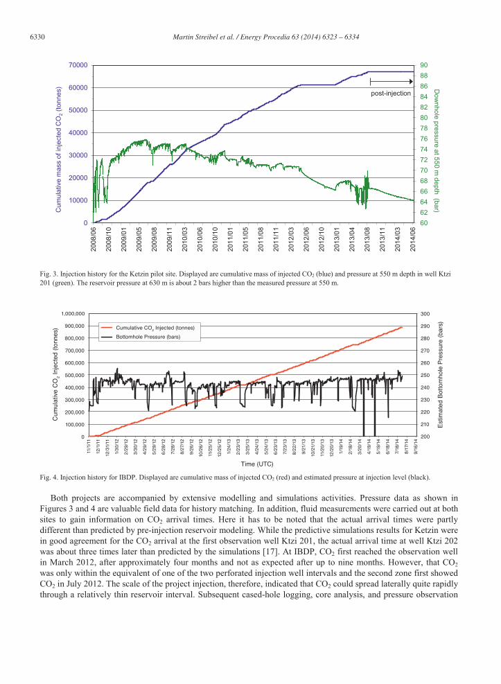
Fig. 3. Injection history for the Ketzin pilot site. Displayed are cumulative mass of injected CO2 (blue) and pressure at 550 m depth in well Ktzi 201 (green). The reservoir pressure at 630 m is about 2 bars higher than the measured pressure at 550 m.
Fig. 4. Injection history for IBDP. Displayed are cumulative mass of injected CO2 (red) and estimated pressure at injection level (black).
Both projects are accompanied by extensive modelling and simulations activities. Pressure data as shown in Figures 3 and 4 are valuable field data for history matching. In addition, fluid measurements were carried out at both sites to gain information on CO2 arrival times. Here it has to be noted that the actual arrival times were partly different than predicted by pre-injection reservoir modeling. While the predictive simulations results for Ketzin were in good agreement for the CO2 arrival at the first observation well Ktzi 201, the actual arrival time at well Ktzi 202was about three times later than predicted by the simulations [17]. At IBDP, CO2 first reached the observation well in March 2012, after approximately four months and not as expected after up to nine months. However, that CO2was only within the equivalent of one of the two perforated injection well intervals and the second zone first showed CO2 in July 2012. The scale of the project injection, therefore, indicated that CO2 could spread laterally quite rapidly through a relatively thin reservoir interval. Subsequent cased-hole logging, core analysis, and pressure observation
60
62
64
66
68
70
72
74
76
78
80
82
84
86
88
90
0
10000
20000
30000
40000
50000
60000
70000
2008
/06
2008
/10
2009
/01
2009
/05
2009
/08
2009
/11
2010
/03
2010
/06
2010
/10
2011
/01
2011
/05
2011
/08
2011
/11
2012
/03
2012
/06
2012
/10
2013
/01
2013
/04
2013
/08
2013
/11
2014
/03
2014
/06
Dow
nhole pressure at 550 m depth (bar)C
umul
ativ
e m
ass
of in
ject
ed C
O2
(ton
nes) post-injection

Martin Streibel et al. / Energy Procedia 63 ( 2014 ) 6323 – 6334 6331
confirmed the dominance of flow continuity between lower-quality reservoir baffles spaced vertically within the reservoir.
Both results pronounce the importance of field data for an adequate understanding of a storage reservoir as such a behavior cannot predicted from limited data after site characterization. Hence it is to stress that after new monitoring data became available, which allowed the revisions of the geological model [9] at Ketzin, an excellent agreement of the simulation results with the monitored CO2 arrival times at Ktzi 202 well could be achieved [17].
5. Public perception
Both projects implemented right from the start an open dialogue with project partners which led, once the project planning became more mature, to a dedicated public outreach program.
At Ketzin, a close collaboration with the county officials (e.g. reporting of GFZ to the city council, town hall meetings) and their approach to energy related questions were very helpful. The CO2 storage project was embedded in the community’s strategy for a sustainable energy production which also included renewable energy sources(wind turbines, solar panels and a biogas plant). Hence, acceptance for the pilot project was reached locally and a transparent communication including open houses and weekly possibilities to visit the site for all interested citizens maintained throughout all phases of the life cycle of the site [18]. The outreach has also a regional component with visits at schools and talks on different occasions. It cannot be excluded that the acceptance for the pilot project in Ketzin is good because GFZ is a research institute and the project scale of 100,000 tonnes was never questioned.However, a targeted communication and dissemination programme was able to establish a wide public acceptance for the research activities like the Ketzin project.
Nevertheless implementations of demo-scale CO2 storage sites in Germany have been unsuccessful due to parts of the public refusing to accept the concept of CCS. In general CO2 storage is seen to be too risky and not necessary for a future energy system which should in Germany (according to these people) rely fully on renewable energy sources.
The IBDP industrial collaborator is the Archer Daniels Midland Company (ADM) on whose plant site the project is taking place, who holds the permit for injection, and who is providing the CO2. Early collaboration with ADM included numerous meetings with company managers and staff, and immediate outreach to the Decatur community. This included discussions with the local newspaper, television stations, and a program to bring storage research into the science program of the Decatur schools. Further contacts were made with city, county, and state officials, and information was presented as part of the injection permit hearing, in a meeting to explain surface seismic acquisition, and at an open house held by ADM during drilling of the injection well. All these efforts served to keep the Decatur community fully informed of IBDP project activities and has resulted in project acceptance that has been maintained as the project nears conclusion.
In Decatur, contact with the print and television media was made early in the project to explain project existence and objectives. Contact was made with Decatur schools and teacher workshops were held. The depth of the project, just over 2,000 m for the injection zone, and the extensive subsurface monitoring put in place, helped assure the public that the project would receive continuous oversight and was not an imminent threat to surface and near-surface resources.
6. Conclusions
With regard to the feasibility of onshore CO2 storage in saline reservoirs the pilot project Ketzin and the demonstration-scale IBDP project have proven that safe operation of a CO2 storage site at different scales is possible. Not all of the tested and applied technologies have worked all of the time (continuously) or could answer up to the expectations but that is part of science and therefore the safe option of pilot and demonstration scaleprojects were chosen. Yet, the picture seems complete enough and the record of accomplishment solid enough to recognize the value of these pilot and demonstration scale project.
Taking the different scales into account the CO2 injection infrastructure can be regarded as similar and the monitoring systems are comparable and also reflect site specific characteristics. Every test project from small pilot to major demonstration scale contributes to the science of carbon storage in different ways. Initially, geology plays

6332 Martin Streibel et al. / Energy Procedia 63 ( 2014 ) 6323 – 6334
the key role in site selection. The established metrics of capacity, injectivity and containment as interrelated requirements must be sought in a reservoir-seal system that may be used for geological CO2 storage. At Decatur, the reservoir is thick, but the plume is relatively thin, such that geophysical detection is challenging. Not so at Ketzin, although the overall reservoir is much thinner. The geomechanical conditions at Decatur, combined with the rate and pressure of injection, combine to induce microseismic events. No such events occurred at Ketzin. It is important to note these differences and similarities in order to move the science of carbon storage forward. Certainly comparisons between projects, such as presented herein, are a way in which to help lay the groundwork for larger demonstration projects to begin to approach the scale at which carbon storage must be deployed to be effective in mitigating climate impacts.
Project scale presents opportunities for gaining knowledge at different levels with respect to geological CO2storage. Ketzin was one of the first CO2 storage sites in 2008 using a saline reservoir with a comprehensive monitoring program that showed that geological storage of CO2 runs safely on a pilot scale. Nowadays a pilot site with truck-delivered CO2 may inject intermittently or at a low rate and is suitable to address elements of behavior of surface facilities and wellbore tubulars, injectability at rates tied to CO2 supply, response of the reservoir and possibly the seal and testing of environmental monitoring strategies. Moreover a pilot site gives a certain level of flexibility as injection can be started without having to make the investment decision for building a pipeline.
What can be learned from the mismatch of the initial CO2 arrival times at both projects is that the injection of a considerable amount of CO2 qualifies a respectable reservoir to be suitable for CO2 storage in a saline reservoir.Preferential pathways and blocking layers within a reservoir cannot be fully determined from point measurements and seismic. Therefore with the current understanding of CO2 storage in 2014, pilot projects represent a good approach to test and understand different geological reservoirs, a way to train staff for CO2 storage and demonstrate the safe operation of a storage site to gain confidence in local public. Nevertheless to progress CO2 storage as a climate mitigation measure pilot projects make most sense if they are coupled to the implementation of demonstration or industry-scale project once the reservoir qualified for CO2 storage.
A demonstration plant at the scale of 1 million tonnes or greater, as the IBDP project, requires more substantial surface facilities, such as a delivery pipeline, and the volume injected will displace more brine, potentially placinggreater mechanical stress on the reservoir due to higher injection rates for a longer time and therefor behaves much more like an industrial CO2 storage. In the case of Decatur, microseismic activity was induced along preexisting planes of weakness that were not detectable pre-injection with geophysical tools. Project developers understood the importance of shallow ground water (90 m depth) and soil flux monitoring for the regulator and the general public, but recognized that cased-hole logging and subsurface sampling/pressure monitoring would be most important if there were a breach of the seal or a failure in the well that allowed CO2 to begin leaking toward shallow potable groundwater and surface ecosystems. Leakage signals from near-surface monitoring would be rather late in this process if leakage were to occur.
Experience to date supports the development of a second project at Decatur which will store 3-4.5 million tonnes over a period of four to five years and is expected to start injection in early 2015. The same saline reservoir as in the present project, the Mt. Simon Sandstone, is the injection target. The total volumes injected at IBDP and to be injected under the second Industrial Sources project at this Decatur location are scalable to annual facility emissions, on the order of 3-4 million tonnes of a single medium-sized pulverized coal power plant.
For the next step, commercial scale injection at multiple sites, monitoring concepts have to be evaluated. Brine migration in the far field of the plume is important as well as the intermediate region between cap rock and fresh water aquifers. With an increasing number and size of storage sites and different projects close to each other the question of potential interaction of storages sites with each other, or CO2 storage with other resources in the subsurface, becomes more important. Therefore a regional monitoring plan and a monitoring zone in between the cap rock of the reservoir formation and the fresh water aquifers might need to be considered. Further, new monitoring tools which employ fiber optic sensors are offering new potential for economic monitoring of multiple parameters continuously at much lower costs.

Martin Streibel et al. / Energy Procedia 63 ( 2014 ) 6323 – 6334 6333
Acknowledgements
We acknowledge the technical help of Daniel Byers, Illinois State Geological Survey, to this article.We acknowledge the funding for the Ketzin project received from the European Commission (6th and 7th
Framework Program), two German ministries - the Federal Ministry of Economics and Technology and the Federal Ministry of Education and Research - and industry since 2004. The ongoing R&D activities are funded within the project COMPLETE by the Federal Ministry of Education and Research within the GEOTECHNOLOGIEN Program. Further funding is received by VGS, RWE, Vattenfall, Statoil, OMV and the Norwegian CLIMIT programme. We also acknowledge the funding for the AUGE project by the Federal Ministry of Education and Research within the GEOTECHNOLOGIEN Program (this is publication GEOTECH- 2219).
The demonstration project at Decatur, Illinois, is funded by the U.S Department of Energy (DOE) under the Regional Carbon Sequestration Partnerships program in collaboration with the Archer Daniels Midland Company (ADM), Schlumberger Carbon Services, and the Illinois State Geological Survey at the University of Illinois. The Midwest Geological Sequestration Consortium is funded by the U.S. Department of Energy through the National Energy Technology Laboratory (NETL) via the Regional Carbon Sequestration Partnership Program (contract number DE-FC26-05NT42588) and by a cost share agreement with the Illinois Department of Commerce and Economic Opportunity, Office of Coal Development through the Illinois Clean Coal Institute.
References
[1] IPCC. Technical Summary. In: Edenhofer, O, Pichs-Madruga R, Sokona Y, Farahani E, Kadner S, Seyboth K, Adler A, Baum I, Brunner S, Eickemeier P, Kriemann B, Savolainen J, Schlomer S, von Stechow C, Zwickel T, Minx JC, editors. Climate Change. Mitigation of Climate Change. Contribution of Working Group III to the Fifth Assessment Report of the Intergovernmental Panel on Climate Change, Chapter 6,Cambridge University Press, Cambridge, United Kingdom and New York, NY, USA; 2014.
[2] IPCC, 2005: IPCC Special Report on Carbon Dioxide Capture and Storage. Prepared by Working Group III of the Intergovernmental Panel on Climate Change, Chapter 5 [Metz, B., O. Davidson, H. C. de Coninck, M. Loos, and L. A. Meyer (eds.)]. Cambridge University Press, Cambridge, United Kingdom and New York, NY, USA, 442 pp.
[3] Würdemann H, Möller F, Kühn M, Heidug W, Christensen NP, Borm G, Schilling FR. CO2SINK - From site characterisation and risk assessment to monitoring and verification: One year of operational experience with the field laboratory for CO2 storage at Ketzin, Germany. Int J Greenhouse Gas Control 2010; 4, 6: 938-951. http://doi.org/10.1016/j.ijggc.2010.08.010
[4] Midwest Geological Sequestration Consortium. An Assessment of Geological Carbon Sequestration Options in the Illinois Basin, Final Report, Phase I. US Department of Energy, Contract DE-FC26-03NY41994, National Energy Technology Laboratory, Morgantown, WV (2005).
[5] Morse D, Leetaru H. Reservoir Characterization and Three –Dimensional Models of Mt. Simon Gas Storage in the Illinois Basin. IllinoisState Geological Survey, Champaign, IL (2005).
[6] Leetaru HE, Frailey S, Morse D, Finley R, Rupp J, Drahozval J, McBride J. Carbon sequestration in the Mt. Simon Sandstone saline reservoir. In: Grobe M, Pashin JC, Dodge RL (eds.), Carbon dioxide sequestration in geological media - State of the science: AAPG Studies in Geology 2009: 59 .
[7] Finley R, Fraliey SM, Leetrau HE, Ozgur S, Marcia LC, Marsteller S. Early Operational Experience at a One-million Tonne CCS Demonstration Project, Decatur, Illinois, USA, Energy Procedia, 2013; 37, DOI: 10.1016/j.egypro.2013.06.544.
[8] Förster A, Giese R, Juhlin C, Norden B, Springer N, CO2SINK Group. The Geology of the CO2SINK Site: From Regional Scale to Laboratory Scale. Energy Procedia, 2009: 1, (1): 2911-2918.
[9] Norden B, Frykman P. Geological modelling of the Triassic Stuttgart Formation at the Ketzin CO2 storage site, Germany. Int J of Greenhouse Gas Control 2013; 19: 756-774.
[10] National Academy of Sciences. Induced Seismicity Potential in Energy Technologies. National Academy of Sciences, Washington, DC (2013).
[11] Liebscher A, Möller F, Bannach A, Köhler S, Wiebach J, Schmidt-Hattenberger C, Weiner M, Pretschner C, Ebert K., Zemke J. Injection operation and operational pressure-temperature monitoring at the CO2 storage pilot site Ketzin, Germany - Design, results, recommendations. Int J Greenhouse Gas Control 2013; 15: 163-173.
[12] http://www.sequestration.org/resources/PAGOct2013Presentations/02-Overview_RFinley_PAG_2013trm.pdf [13] Giese R, Henninges J, Lüth S, Morozova D, Schmidt-Hattenberger C, Würdemann H, Zimmer M, Cosma C, Juhlin C. CO2SINK Group.
Monitoring at the CO2SINK Site: A Concept Integrating Geophysics, Geochemistry and Microbiology. Energy Procedia 2009; 1 (1): 2251-2259.
[14] Martens S, Moeller F, Streibel M, Liebscher A, and the Ketzin Group. Completion of five years of safe CO2 injection and transition to the post-closure phase at the Ketzin pilot site. Energy Procedia 2014; in press.
[15] Locke R, Larssen D, Salden W, Patterson C, Kirksey J, Iranmanesh A, Wimmer B, Krapac I. Preinjection reservoir fluid characterization at aCCS demonstration site: Illinois Basin – Decatur Project, USA. Energy Procedia, 2013; 37: 6426-6433.

6334 Martin Streibel et al. / Energy Procedia 63 ( 2014 ) 6323 – 6334
[16] Freiburg J, Morse D, Leetaru H, Hoss R, Yan QA. Depositional and Diagenetic Characterization of the Mt. Simon Sandstone at the Illinois Basin – Decatur Project (IBDP) Carbon Capture and Storage (CCS) Site: Decatur, Illinois USA. Illinois State Geological Survey, Champaign, IL (2014).
[17] Kempka T, Kühn M. Numerical simulations of CO2 arrival times and reservoir pressure coincide with observations from the Ketzin pilot site, Germany. Environmental Earth Sciences 2013: 70, 8: 3675-3685, doi: 10.1007/s12665-013-2614-6.
[18] Szizybalski A, Kollersberger T, Möller F, Martens S, Liebscher A, Kühn M. The Ketzin pilot site, Germany - A communication concept that supports the research on CO2 storage. Energy Procedia 2014; 51: 274-280. doi: 10.1016/j.egypro.2014.07.032.