From Network to Spectrum: A Software-Defined Networking ...
128
UNIVERSIDADE FEDERAL DO RIO GRANDE DO SUL INSTITUTO DE INFORMÁTICA PROGRAMA DE PÓS-GRADUAÇÃO EM COMPUTAÇÃO MARCELO ANTONIO MAROTTA From Network to Spectrum: A Software-Defined Networking (SDN)-based decision-making system for H-CRAN Thesis presented in partial fulfillment of the requirements for the degree of Doctor of Computer Science Advisor: Prof. Dr. Juergen Rochol Porto Alegre January 2019
Transcript of From Network to Spectrum: A Software-Defined Networking ...

UNIVERSIDADE FEDERAL DO RIO GRANDE DO SULINSTITUTO DE INFORMÁTICA
PROGRAMA DE PÓS-GRADUAÇÃO EM COMPUTAÇÃO
MARCELO ANTONIO MAROTTA
From Network to Spectrum: ASoftware-Defined Networking (SDN)-based
decision-making system for H-CRAN
Thesis presented in partial fulfillmentof the requirements for the degree ofDoctor of Computer Science
Advisor: Prof. Dr. Juergen Rochol
Porto AlegreJanuary 2019
CIP — CATALOGING-IN-PUBLICATION
Marotta, Marcelo Antonio
From Network to Spectrum: A SDN-based decision-makingsystem for H-CRAN / Marcelo Antonio Marotta. – Porto Alegre:PPGC da UFRGS, 2019.
128 f.: il.
Thesis (Ph.D.) – Universidade Federal do Rio Grande do Sul.Programa de Pós-Graduação em Computação, Porto Alegre, BR–RS, 2019. Advisor: Juergen Rochol.
1. Heterogeneous cloud radio access networks. 2. Decisionmaking system. 3. Software-defined networking. I. Rochol, Juer-gen. II. Título.
UNIVERSIDADE FEDERAL DO RIO GRANDE DO SULReitor: Prof. Rui Vicente OppermannVice-Reitora: Profa. Jane Fraga TutikianPró-Reitor de Pós-Graduação: Prof. Celso Giannetti Loureiro ChavesDiretora do Instituto de Informática: Profa. Carla Maria Dal Sasso FreitasCoordenador do PPGC: Prof. João Luiz Dihl CombaBibliotecária-chefe do Instituto de Informática: Beatriz Regina Bastos Haro

“The truth isn’t always beauty,
but the hunger for it is.”
— MS. NADINE GORDIMER


ACKNOWLEDGMENTS
I would like to express my gratitude to my mother Maria Aparecida Sousa Gay
Marotta and also my sister Samantha Marotta. They are my life examples, my idols,
and my reasons to go further. In addition, I would like to thank my stepfather, nephew,
and niece, Antonio Donizete Silva Santos, Yago Marotta Diniz, and Maria Paula Marotta
Diniz, for all the love and joy shared with me.
I am grateful to my fiancée, Renata Sayuri Muranaka, who spent the last decade
by my side. She always listened carefully to my problems and tried her best to help me.
My best friend, my love, and my happiness.
I would like to express my gratitude to those that I cannot say it in person, my
father Antonio Ernesto Marotta, my grandmother Maria da Penha Sousa Gay, and my
grandfather Sebastião Milton Gay. They are not among us anymore, however, they are
still alive in my heart, dreams, and thoughts. I am also grateful to my family, which
always took care of me with love and joy.
I would like to express my gratitude to my advisor, prof. Juergen Rochol for all
the encouragement and guidance to become a better researcher. In addition, I would like
to give a special thanks to my professor Cristiano Bonato Both for his good advices and
time, always giving his best effort and being present during my whole Ph.D pushing me
to become a better version of myself everyday. Also, I am thankful to my external advisor
professor Luiz DaSilva, who received me during my internship in Dublin and never left
me ever since, participating in the whole development of this work and of myself.
I am grateful to all of my friends, mainly, Matias Schmuneck, Iulislois Zacarias,
Gustavo Araujo, Juliano A. Wickboldt, Leonardo R. Faganello, Lucas Bondan, Luiz
Otávio V. B. Oliveira, Anderson Silva, Maicon Kist, Henrique Resende, Ian Schilling,
Pedro Isolani, and Wanderson P. de Jesus. All of them were always present making this
slice of my life enjoyable and happy.
I would like to thank also the rest of my colleagues, friends, professors, and staff
of the Informatics Institute from UFRGS, by their good work and assistance. Mainly,
Luís Otavio and Carlos Alberto (Cabeto), by their support during the accomplishment of
this work.
Finally, I would like to express my gratitude to those people that influenced me
directly or indirectly during my Ph.D and also my life. Thank you all.

ABSTRACT
Heterogeneous Cloud Radio Access Networks (H-CRAN) incorporate Heterogeneous
Networks (HetNet) and Cloud Radio Access Networks (C-RAN) concepts for next-generation
cellular networks. H-CRAN exploits the heterogeneity of macro and small cells from Het-
Net, enabling cellular networks to achieve a higher spectral efficiency. Meanwhile, con-
cepts from C-RAN involving baseband units and remote radio heads enable H-CRAN to
insert a centralized point of processing for cellular networks, reducing capital and opera-
tional expenditures. Although H-CRAN brings several opportunities to cellular networks,
it is not free from challenges. Among the different challenges existent, we highlight
the most relevant ones, (a) high intercell interference; (b) critical latency constraints in
long-distance wireless signal processing; and (c) poor allocation of processing resources.
To address these challenges, we propose a Software-Defined Networking (SDN)-based
decision-making system able to be programmatically changed to make decisions that
can decrease interference, meet delay constraints, and mitigate processing underusage
for long-term operation of an H-CRAN. By adding concepts of SDN with a simplified
object-oriented API, it is possible to logically centralize the control of H-CRAN consid-
ering a pool of physically distributed equipment. The methodology employed to show
the feasibility of the proposed approach is based on the development of a prototype that
supports a wide range of decision algorithms. This prototype was evaluated in three case
studies conducted on a simulated environment based on 3GPP specification for simula-
tors. In the first case study, we evaluate the network overload implied by adding an SDN-
based decision-making system to H-CRAN. Afterwards, a decision algorithm is executed
to exploit resource sharing deciding which elements of an H-CRAN can be used by two
operators interchangeably to reduce interference and increase spectrum efficiency at the
spectrum level. The third case study shows that the distance between cloud and remote
radio heads must be considered in processing power allocation decisions and also when
assigning a virtual baseband unit to the cloud. Evaluating the case studies becomes clear
the need of an SDN-based decision-making system in H-CRAN to address the inherent
challenges of these networks.
Keywords: Heterogeneous cloud radio access networks. decision making system. software-
defined networking.

Da Rede para o Espectro: um sistema de tomada de decisão baseado em SDN para
H-CRAN
RESUMO
As redes de acesso a rádio heterogêneas baseadas em conceito de nuvem (H-CRAN) in-
corporam conceitos de redes heterogêneas (HetNet) e redes de acesso de rádio em nuvem
(C-RAN) para serem utilizadas nas redes de celulares da próxima geração. H-CRAN ex-
plora a heterogeneidade das macro e pequenas células das HetNets, permitindo que as
redes de celulares alcancem uma maior eficiência espectral. Já, os conceitos de C-RAN
envolvendo unidades de banda base e cabeças de rádio remotas permitem que a H-CRAN
insira um ponto de processamento centralizado nas redes de celulares, reduzindo os gas-
tos de capital e operacionais. Embora H-CRAN traga várias oportunidades para as redes
de celulares, sua adoção não é livre de desafios. Entre os diferentes desafios existentes,
destacamos os mais relevantes, (a) alta interferência intercelular; (b) restrições de latên-
cia críticas no processamento de sinal sem fio de longa distância; e (c) má alocação de
recursos de processamento. Para enfrentar esses desafios, propomos um sistema de deci-
são baseado em software-determinado por rede (SDN) capaz de ser modificado para criar
decisões que possam diminuir a interferência, atender às restrições de atraso e mitigar a
subutilização de processamento para o funcionamento a longo prazo de uma H-CRAN.
Ao adicionar conceitos de SDN e uma API orientada a recursos (ROA) simplificada, é
possível centralizar logicamente o controle de H-CRAN considerando um conjunto de
equipamentos distribuídos fisicamente. A metodologia empregada para mostrar a viabili-
dade da abordagem proposta baseia-se no desenvolvimento de um protótipo que suporte
uma ampla gama de algoritmos de decisão. Este protótipo foi avaliado em três estudos de
caso realizados em um ambiente simulado com base na especificação 3GPP para simula-
dores. No primeiro estudo de caso, avaliamos a sobrecarga de rede implícita ao adicionar
um sistema de decisão baseado em SDN para H-CRAN. Posteriormente, um algoritmo
de decisão é executado para explorar o compartilhamento de recursos, decidindo quais
elementos de uma H-CRAN podem ser utilizados por duas operadoras de forma inter-
cambiável para reduzir a interferência e aumentar a eficiência espectral. O terceiro estudo
de caso mostra que a distância entre nuvem e cabeças de rádio remotas deve ser conside-
rada nas decisões de alocação de processamento. Ao avaliar cada um dos estudos de caso,
fica evidente a necessidade de um sistema de decisão baseado em SDN em H-CRAN para

atacar os desafios inerentes dessas redes.
Palavras-chave: Redes de acesso a rádio heterogêneas baseadas em conceito de nuvem;
Sistema de tomada de decisão; Redes definidas por software.
ACRONYM
3GPP Third Generation Partnership Project
ABS Almost Blank Subframes
API Application Program Interface
AWGN Additive White Gaussian Noise
BBU Base-Band Unit
BER Bit Error Rate
BILP Binary Integer Linear Programming
BS Base Station
C-RAN Cloud Radio Access Networks
CAPEX Capital Expenditure
CA Carrier Aggregation
CC-CRRM Cloud-Computing-based Cooperative Radio Resource Management
CC-CSON Cloud-Computing based Cooperative Self Organization Networking
CC-CoMP Cloud-Computing-based Coordinated Multi Point
CP Central Processor
CRRM Cooperative Radio Resource Management
CSI Channel State Information
CSON Cooperative Self-Organizing Network
CoMP Coordinated Multipoint Transmission and Reception
D2D Device-to-Device communication
DPoA Destination Point-of-Access
DSA Dynamic Spectrum Access
DSA Dynamic Spectrum Access
Eb/No Energy per bit to noise power spectral density ratio
F-RAN Fog Radio Access Networks
FBMC Filter Bank MultiCarrier
FEC Forward Error Correction
FFT Fast Fourier Transform
GPP General Purpose Processor
H-CRAN Heterogeneous Cloud Radio Access Networks
HARQ Hybrid Automatic Repeat reQuest
HSPA High Speed Packet Access
HetNet Heterogeneous Networks
Hz hertz
JT Joint Transmission
KPI Key Performance Indicator
LSA Licensed Shared Spectrum Access
LTE-A Long Term Evolution Advanced
LTE Long Term Evolution
MAC Media Access Layer
MDC Micro Data Centers
MIMO Multiple-Input Multiple-Output
MME Mobility Management Entity
NFV Network Function Virtualization
OFDMA Orthogonal Frequency-Division Multiple Access
OFDM Orthogonal Frequency Division Multiplexing
ONF Open Networking Foundation
OPEX Operational Expenditure
PER Packet Error Rate
PHY Physical Layer
PoA Point-of-Access
QAM Quadrature Amplitude Modulation
QSI Queue State Information
QoE Quality of Experience
QoS Quality of Service
RAN Radio Access Network
RAT Radio Access Technologies
RF Radio Frequency
RRH Remote Radio Head
RSSI Received Signal Strength Indication
SDN Software-Defined Networking
SDR Software-Defined Radio
SDWN Software-Defined Wireless Networking
SINR Signal-to-Interference-plus-Noise Ratio
SNR Signal-to-Noise ratio
UE Users Equipment
WCDMA Wideband Code Division Multiple Access
WiFi Wireless Fidelity
eICIC enhanced Inter-Cell Interference Control
eNB E-UTRAN Node B
km Kilometer
ms millisecond
vBBU Virtual Baseband Unit
VNF Virtual Network Function

LIST OF FIGURES
Figure 2.1 H-CRAN: Resource levels.............................................................................31Figure 2.2 Optimum number of antennas and spectrum per user ...................................34Figure 2.3 H-CRAN: Spectrum level..............................................................................35Figure 2.4 H-CRAN: Infrastructure level .......................................................................37Figure 2.5 H-CRAN: Network level ...............................................................................40
Figure 4.1 H-CRAN system............................................................................................59Figure 4.2 Round-trip delay components in a Cloud Radio Access Networks (C-RAN).61
Figure 5.1 Centralized decision making system architecture based on SDN concepts. .72
Figure 6.1 H-CRAN with SDWN deployment ...............................................................90
Figure 7.1 Average throughput experienced by mobile subscribers ...............................93Figure 7.2 Percentage of communications performed relative to the number of in-
terferers ...................................................................................................................94Figure 7.3 Average energy consumption per RRH .........................................................95Figure 7.4 Total of control messages in each scenario....................................................96Figure 7.5 SDWN control messages frequency and bandwidth consumption................97Figure 7.6 Small cells without resource sharing .............................................................98Figure 7.7 Saturation of small cells ................................................................................99Figure 7.8 Small cells resource sharing ........................................................................100Figure 7.9 Maximum distance between an RRH and the MDC responsible for pro-
cessing its signals, as a function of available processing capabilities availableat the MDC and the SNR experienced on the wireless channel. ..........................103
Figure 7.10 Maximum distance between an Remote Radio Head (RRH) and theMicro Data Centers (MDC) responsible for processing its signals, as a func-tion of the target Bit Error Rate (BER) and the Signal-to-Noise ratio (SNR)experienced on the wireless channel.....................................................................104
Figure 7.11 Processing consumption according to different values of al pha...............105Figure 7.12 Average number of active MDCs per second for the biased decisions
influenced by al pha. .............................................................................................106Figure 7.13 Tradeoff between processing power consumption and consolidation in
the Heterogeneous Cloud Radio Access Networks (H-CRAN). ..........................107


LIST OF TABLES
Table 2.1 H-CRAN trending technologies ......................................................................42
Table 4.1 Notation...........................................................................................................58
Table 5.1 SDWN controller responsibilities ...................................................................75
Table 6.1 SDWN southbound interface...........................................................................88
Table 7.1 Validation parameters ....................................................................................101
Table 8.1 List of research activities conducted in 2014 ................................................111Table 8.2 List of research activities conducted in 2015 ................................................112Table 8.3 List of research activities conducted in 2016 ................................................112Table 8.4 List of research activities conducted in 2017 ................................................113Table 8.5 List of research activities conducted in 2018 ................................................113

CONTENTS
1 INTRODUCTION.......................................................................................................211.1 Fundamental Question, Hypothesis & Research Questions ...............................241.2 Main Contributions ................................................................................................251.3 Organization............................................................................................................262 SOFTWARE-DEFINED NETWORKING AND HETEROGENEOUS CLOUD
RADIO ACCESS NETWORK OVERVIEW ....................................................292.1 Revisiting SDN Concepts........................................................................................292.2 H-CRAN characterization......................................................................................302.2.1 Spectrum Level ......................................................................................................322.2.2 Infrastructure Level................................................................................................352.2.3 Network level .........................................................................................................392.2.4 Trending technologies............................................................................................413 RELATED WORK .....................................................................................................453.1 Related Work of an SDN-based decision-making system ...................................453.2 H-CRAN Challenges...............................................................................................483.2.1 High Intecell Interference ......................................................................................483.2.2 Critical delay constraints in long distance wireless signal processing ..................513.2.3 Poor processing power allocation ..........................................................................533.2.4 Identified gaps........................................................................................................554 SYSTEM MODEL......................................................................................................574.1 Modeling an H-CRAN ............................................................................................574.2 Modeling H-CRAN Challenges..............................................................................624.2.1 Interference Reduction with Resource Sharing in H-CRAN.................................634.2.2 Maximum Distance Between MDC and RRH under Delay Considerations .........654.2.3 Processing Power Underusage in H-CRAN...........................................................665 AN SDN-BASED DECISION-MAKING SYSTEM IN H-CRAN..........................715.1 Architecture.............................................................................................................715.1.1 Software-Defined Wireless Networking (SDWN) Controller Responsibilities .....745.2 Decision algorithms.................................................................................................795.2.1 Minimal Interference with Maximum Throughput though a Resource Sharing
Decision Algorithm................................................................................................795.2.2 Maximizing Distance Between MDC and RRH Algorithms.................................805.3 Minimizing Processing Power Underusage Algorithm........................................826 PROTOTYPE AND INTERFACE DEFINITION ...................................................876.1 Controller Interface ................................................................................................876.2 H-CRAN and decision making system prototype ................................................896.2.1 H-CRAN prototype................................................................................................896.2.2 Decision Making System Prototype.......................................................................907 RESULTS.....................................................................................................................937.1 Architecture Benefits and Communication Cost..................................................937.1.1 Throughput and Energy benefits of SDWN in H-CRAN ......................................937.1.2 Control message cost of SDWN in H-CRAN........................................................957.2 Decision algorithms case study and results ..........................................................977.2.1 Throughput Maximization using Resource Sharing in H-CRAN..........................977.2.2 Analyzing the Distance between MDC and RRH in an H-CRAN ......................1017.3 Minimizing processing power underusage in H-CRAN ....................................1048 CONCLUSIONS .......................................................................................................1098.1 Research Agenda & Development .......................................................................111

REFERENCES.............................................................................................................115APPENDIX A — PUBLISHED ARTICLES............................................................123APPENDIX B — CORRELATED PUBLISHED ARTICLES...............................125APPENDIX C — CO-AUTHORED PUBLISHED ARTICLES ............................127
21
1 INTRODUCTION
Data traffic in cellular networks has increased significantly over the past few years.
Arguably, the current architecture of cellular networks, largely based on the deployment
of macrocells, will not be able to accommodate the ever-growing traffic and the number of
connected Users Equipment (UE) (AGYAPONG et al., 2014). To cope with this increase
in traffic and number of connections, industry, and academia have been designing and
gradually deploying the fifth generation (5G) cellular infrastructure. This infrastructure
envisages denser and heterogeneous deployments in the Radio Access Network (RAN)
through a massive number of small cells (e.g., femtocells and picocells) to cover specific
geographical areas, overlapping with existing macrocells. The high density of 5G RAN
increases its cost dramatically, turning it unsustainable for operators to cope with its de-
ployment considering current business models. This scenario motivated the introduction
of a new candidate architecture for 5G, called H-CRAN (PENG et al., 2014).
H-CRAN is an advanced radio access network architecture that takes the full ad-
vantages of both Heterogeneous Networks (HetNet) and C-RAN concepts to address the
future growth of data traffic, and Quality of Service (QoS) demand of 5G (OSSEIRAN
et al., 2014). In particular, from HetNets, a massive number of small cells of differ-
ent Radio Access Technologies (RAT), e.g., Long Term Evolution (LTE) and Wireless
Fidelity (WiFi), are spread along dense areas with high traffic demand to increase the
overall network capacity (DAMNJANOVIC et al., 2011). The C-RAN, in turn, intro-
duces the cloud computing paradigm in the cellular network architecture, where a set of
low-power nodes, also referred to as RRH, connect to a Virtual Baseband Unit (vBBU) in
the cloud to have their signal cooperatively processed (China Mobile Research Institute,
2011). H-CRAN architecture enables the deployment of dense HetNets with centralized
cloud-based processing, enhancing the spectrum and the energy efficiencies.
The processing centralization provided in H-CRAN reduces significantly the cost
for operators to deploy a sustainable infrastructure to 5G (PENG et al., 2014). Cheaper
than a Base Station (BS), an RRH is composed of an array of antennas with their front-
end connected to an optical interface to offload their workload, which comprises a set
of in-phase and quadrature sample constituents (CPRI, Common Public Radio Interface,
2015). This workload potentially traverses multiple hops within an optical infrastructure,
i.e., fronthaul, until arriving in the cloud where it will be processed. This cloud, in turn,
comprises several General Purpose Processor (GPP) with plenty of processing capacity.

22
Within the cloud, processing resources regarding GPPs and memory are allocated for
vBBU that computes the arrived workload (I et al., 2014)(QIAN et al., 2015). A controller
within the cloud determines the processing resources allocated for each vBBU according
to the arrived workload, which is directly influenced by the density of RRHs and UEs
connected, their demand in the RAN, and their channel conditions, e.g., SNR (CHECKO
et al., 2015)(SCHIMUNECK et al., 2017).
The H-CRAN presents several resources, e.g., channels, RRHs, and processors,
that are spread along the RAN, fronthaul, and cloud. To classify these resources, we
organized H-CRAN in three levels: (i) spectrum; (ii) infrastructure; and (iii) network
(MAROTTA et al., 2015). In the first level, the operator’s licensed and unlicensed portion
of the radio spectrum is characterized according to four domains i.e., time, frequency,
space, and power. In the second, each active element, e.g., RRH and optical links, as well
as passive element, e.g., buildings and masts, that composes the H-CRAN are considered
resources that belong to the infrastructure level. In the third, spectrum and infrastructure
are abstracted in sharing entities that are described according to high-level metrics, such
as throughput, latency, and processing capacity. New requirements and challenges emerge
from each resource level that must be addressed and managed to maintain H-CRAN oper-
ant. Instead of raising all requirements and challenges from H-CRAN, we prefer to focus
on the main problems of each level that have a clear link between them (CHECKO et al.,
2015):
1. High intercell interference: The dense deployment of small cells in the RAN gener-
ates interference that can cause signal intermittent and compromise the RAN spec-
tral efficiency at spectrum level (ROST; BERNARDOS, 2014).
2. Critical latency constraints in long-distance wireless signal processing: the remote
processing adds additional delay that prevent RRHs to be placed farther than few
tens of Kilometers (kms) from the Base-Band Unit (BBU) hindering the centraliza-
tion at infrastructure level (PENG et al., 2016).
3. Poor allocation of processing resources: as during the day different UEs may join
and leave the RAN at any time with unpredictable channel conditions, process-
ing resources in the BBU may naturally become unused or overloaded due to the
dynamicity in the RAN characterizing underuse of these resources at the network
level (CHECKO et al., 2015).
Recent research effort suggests that the inter-cell interference in H-CRAN can be miti-
23
gated through decisions involving power and spectrum resources taken by sophisticated
enhanced Inter-Cell Interference Control (eICIC) mechanisms using Coordinated Multi-
point Transmission and Reception (CoMP) and beamforming communication processed
in the cloud as a single and centralized physical processing entity (PENG et al., 2015)
(GERASIMENKO et al., 2015). In this case to account not just for radio but as well as
for processing, a power-efficient cross-layer framework can be used to make decisions,
e.g., which processors will be allocated to process an RRH, to perform optimal alloca-
tion of resources (BHAUMIK et al., 2012) (TANG; TAY; QUEK, 2015). This framework
is based on the assumption of a fully centralized H-CRAN architecture to optimize the
allocation of resources, which was proven to be infeasible due to the limitation of the
maximum distance between BBU and RRH to meet delay constraints (China Mobile Re-
search Institute, 2011) (AGYAPONG et al., 2014).
Since delay constraints prevent the full centralization of H-CRAN, the remote
processing must be put physically closer to RRHs and spread along the RAN. In this
case, MDCs are distributed within the RAN becoming part of a distributed cloud (PENG
et al., 2016). In this distributed cloud, the decision to place a vBBUs within an MDC
determines the number of RRHs that can reuse the processing resources available. There-
fore, the decision where to place a vBBU determines how efficient processing resources
are used by allocating the exact number of physical equipment required, also referred to
as consolidation (MATINMIKKO et al., 2014)(MUSUMECI et al., 2016). Usually, the
decisions are taken using snapshots of the status of the H-CRAN resource levels being
computed by algorithms to avoid inter-cell interference, meet delay constraints, and mit-
igate the underusage of processing resources (BHAUMIK et al., 2012)(MUSUMECI et
al., 2016)(CARAPELLESE; TORNATORE; PATTAVINA, 2014)(CARAPELLESE et al.,
2013)(TANG; TAY; QUEK, 2015)(SCHIMUNECK et al., 2017). However, the hetero-
geneity and dynamicity of the RAN inserts fluctuations in the usage of radio and process-
ing resources during runtime compromising consolidation within the pool for long time
operation. As the vast majority of solutions focus on the optimization of a static version
of H-CRAN resources from which all the status are quantized and captured as a snapshot,
they are unable to address the dynamicity of H-CRAN during runtime. In this case, it is
required a decision-making system able to manage wireless, fronthaul, and cloud making
decision to decrease interference, meeting delay constraints, and to mitigate processing
underusage for long-term operation, leading to the following fundamental question.
24
1.1 Fundamental Question, Hypothesis & Research Questions
Fundamental Question: How to design a decision-making system able to address the
challenges inherent of H-CRAN?
This thesis presents the following hypothesis to overcome the presented limitation
in the context of H-CRAN.
Hypothesis: The decisions in an H-CRAN can be taken by an SDN-based system able
to address different challenges considering delay constraints.
The following research questions (RQ) associated with the hypothesis are defined
and presented to guide the investigations conducted in this thesis.
• What relevant information and technology are required to make decisions within an
H-CRAN considering RAN, fronthaul, and cloud?
• What are the main decisions to be taken in an H-CRAN considering different limi-
tations when adjusting the RAN, fronthaul, and cloud?
• How can an SDN-based system make decisions to reallocated resources to en-
hance their usage for long-term operations considering the limitations inherent of
H-CRAN?
In this thesis, we propose an architecture that host decision algorithms able to
manage wireless, fronthaul, and cloud aiming to decrease inter-cell interference, meeting
delay constraints, and enhancing processing power allocation in H-CRAN. By adding
concepts of SDN to H-CRAN with a simplified object-oriented Application Program In-
terface (API), it is possible to logically centralize the control of H-CRAN considering
a pool of physically distributed equipment. As an additional feature, SDN enables pro-
grammability at the control level enabling operators to write and run personalized de-
cision algorithms considering wireless, fronthaul, and cloud to achieve enhanced usage
of resources and consolidation. The proposed API allows for more integrated resource
management by offering high-level abstractions and operations to handle different sorts
of resources (i.e., computing, optical, and wireless links). Further, administrators can use
the API to collect information from H-CRAN to use this information when deploying or
optimizing algorithms.
It is worthy mentioning that just applying SDN concepts in H-CRAN is not novel
25
by itself. Most of current solutions rely on the well known OpenFlow1 protocol (YANG et
al., 2016) (PENG et al., 2014). These solutions usually propose changes to the OpenFlow
API to support wireless and fronthaul related functions. However, this type of changes
have two drawbacks: (i) wireless and fronthaul information must be captured and adapted
to met the OpenFlow API; and (ii) change the real purpose of OpenFlow from control
network flows to control H-CRAN substratum. Opposite to that, we do a step further by
rethinking the whole application of SDN to H-CRAN from scratch to control and manage
the H-CRAN substratum without changing the already well established protocols but also
using them combined with the new proposed API.
The methodology employed to show the feasibility of the proposed architecture
and API is based on the development of a prototype that supports a wide range of deci-
sion algorithms. This prototype was evaluated in four case studies conducted on a simu-
lated environment based on 3GPP specification for simulators (3rd Generation Partnership
Project (3GPP), 2010, Annex A). In the first case study, we evaluate the network overload
implied by adding a centralized SDN-based decision-making system in H-CRAN. Af-
terwards, in the second case study, a decision algorithm is executed to exploit resource
sharing deciding which elements of an H-CRAN can be used by two operators inter-
changeably to reduce interference and increase spectrum efficiency at the spectrum level.
The third case study shows that the distance between MDC and RRH must be considered
in processing power allocation decisions and also when assigning a vBBU to an MDC.
Finally, in the fourth case study, we deploy a decision algorithm for long-term operation
of an H-CRAN to optimize processing resources allocated during runtime exploiting the
tradeoff between processing consumption and consolidation regarding average number of
MDCs active during execution.
1.2 Main Contributions
Throughout the development of this study, many contributions are expected re-
garding conceptual advancements in the state-of-the-art of decision-making systems in
the context of H-CRAN. Some of these contributions are listed as follows:
1. Rethinking design principles of SDN to control H-CRAN influencing its decision-
making process;
1OpenFlow - https://www.opennetworking.org/ja/sdn-resources-ja/onf-specifications/openflow
26
2. Adding more flexibility in resource management through an SDN-based decision-
making system to enhance performance in RAN, fronthaul, and processing pool;
3. Adding support for decision algorithms guaranteeing that delay budgets are not
violated;
4. Creating a programmability environment based on a resource-oriented API, which
allows high-level abstractions for manageable resources;
1.3 Organization
The remainder of this thesis is organized as follows.
In Chapter 2, a brief overview of the evolution of H-CRAN is presented focusing on
the characterization of the different resource levels. Afterwards, discussions are
presented about SDN and its role in the different levels of H-CRAN, interfaces
and standardization efforts, that are fundamental to design an SDN-based decision-
making system.
In Chapter 3, the most relevant state-of-the-art for SDN and decision-making systems are
investigated according to main challenges identified at the spectrum, infrastructure,
and network levels of an H-CRAN. Within this chapter, we also map the most
important decisions to be made according to the literature to tackle the different
challenges presented in H-CRAN. Finally, we highlight the gaps presented in the
literature that serve as motivation to this work.
In Chapter 4, an H-CRAN environment is modeled and presented. Afterward, we present
a problem definition for each of the main challenges covered in this thesis: (i) eICIC
considering resource sharing; (ii) maximum distance between MDC and RRH con-
sidering delay constraints; and (iii) enhanced processing power consumption for
long-term operation H-CRAN.
In Chapter 5, the key concepts that drive this research are presented. These concepts
are organized in the form of a conceptual architecture which includes the main
components of an SDN platform proposed to enable more flexible and integrated
resource management in the context of wireless, fronthaul, and cloud. Afterward,
we present three decisions algorithms to be host by the proposed architecture for
H-CRAN that can address the problems modeled in Chapter 4.
In Chapter 6, the prototype of our architecture is presented. First, we present the resource-

27
oriented API necessary to create the decision algorithms. Afterward, we delve into
details of how the prototype and the decision algorithms were deployed consider-
ing the architecture definitions. Finally, the prototype of our simulated scenario is
presented according to the definitions of the (3rd Generation Partnership Project
(3GPP), 2010, Annex A).
In Chapter 7, four case studies are presented to show the feasibility and benefits of em-
ploying an SDN-based decision-making system in H-CRAN. We start by presenting
a case study to measure the cost of deploying an SDN-based decision-making sys-
tem in H-CRAN and showing the potential benefits when employing it. Afterward,
we evaluated our proposed decision algorithms in the other three case studies. In the
second case study, we show the employment of a software controller in H-CRAN
to achieve enhanced eICIC and resource sharing among operators. The third case
study focuses on decisions taken that influence the tradeoff between distance of
MDC and RRH and processing power when considering delay limitations. Finally,
in the fourth case study, we evaluate the tradeoff of reducing the consumption of
processing resources against achieve better consolidation regarding MDCs active.
In Chapter 8, some final remarks and conclusions are presented. Also, answers to the
fundamental questions proposed are discussed and justified. Finally, an overview of
the development path of this thesis regarding accomplished activities is presented.

28

29
2 SOFTWARE-DEFINED NETWORKING AND HETEROGENEOUS CLOUD RA-
DIO ACCESS NETWORK OVERVIEW
The main objective of this chapter is to characterize SDN concepts, introduc-
ing decision-making system, and highlight the main contributions that an SDN-based
decision-making system can bring to H-CRAN. In this case, in Section 2.1, we start
by briefly revisiting SDN concepts defining a decision-making system. Afterward, we
present an overview of H-CRAN, exploiting its architecture considering different con-
cepts and technical details highlighting the potential of employing an SDN-based decision-
making system.
2.1 Revisiting SDN Concepts
Because of the evidenced benefits of SDN in wired networks, such as network pro-
grammability and flexible operation, it is natural to consider this paradigm as a framework
to deliver the same benefits to wireless networks (PENTIKOUSIS; WANG; HU, 2013).
Before discussing the realization of SDN in H-CRAN, we do a brief review on current
SDN concepts. SDN is conceptually organized in four planes. (i) Application plane,
(ii) Control plane, (iii) Forwarding plane, and (iv) Management plane (WICKBOLDT
et al., 2015). Decision algorithms sitting on the Application plane are designed and im-
plemented by service providers that serve their own subscribers. Decision algorithms
have routines to eventually issue requests for network resources, which are interpreted
and translated into fine-grain configurations by network controllers at the Control plane.
Besides handling requests coming from services, controllers also react upon receiving
events generated by devices from the Forwarding plane (e.g., to recover from failure or
performance degradation). Finally, the Management plane manages the components of an
SDN architecture (e.g., applications, controllers, and devices) by monitoring and tuning
the health of the whole network across planes to meet high-level policies and agreements.
SDN also assumes three main Application Programming Interfaces (APIs): (i)
Northbound API, (ii) Southbound API, and (iii) Management API. The Control plane
provides the Northbound API for service providers to create their network applications.
Controllers, in turn, make use of the Southbound API to interact with devices in the
Forwarding plane, i.e., by issuing low-level instructions and collecting information. The
30
Management API enables the Management plane to handle devices and services in all
other planes, through legacy management protocols, such as SNMP, or new ones, such as
OF-Config1.
A network system built based on SDN concepts enable service providers to deter-
mine the behavior of the network according to decisions taken. These decisions definition
depends directly on the context that they are inserted, e.g., a wired or wireless network,
and the decision-maker objectives, e.g., enhance throughput or prevent interference. For
instance, assuming the native usage of SDN in wired networks through OpenFlow im-
plementations, a decision algorithm can determine the route that a data flow will be sent
through specific devices of the forwarding plane and with a determined configuration,
e.g., QoS class and channel bandwidth. It is worth mentioning that the granularity of a
decision depends on the interfaces, the system implementation, and decision algorithm
objectives. For instance, a decision algorithm can simply be built to decide which devices
will prioritize some data flow, whereas others can specify the packet priority at the level
of link buffers if the system allows to. Although an SDN-based decision-making system
is easily determined and exemplified in a wired network context, for a wireless network,
such as H-CRAN, its potential benefits, design, and implementation still needs to be de-
termined. In this case, next, we characterize H-CRAN inferring the potential benefits of
employing SDN-based decision-making system before following to its proposal.
2.2 H-CRAN characterization
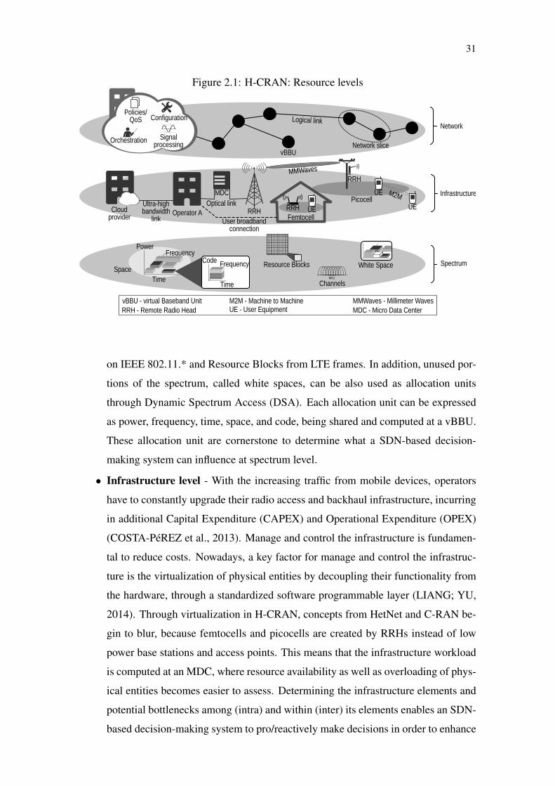
To present an overview of H-CRAN, we divided it in three levels of resources,
depicted in Figure 2.1. For each of these different levels, we present a deeper insight
organized in three Sections, characterizing, highlighting challenges, and presenting po-
tential benefits of employing SDN-based decision-making system to alleviate and address
these challenges. At the end we present main technologies identified that have a clear
relationship with the proposal of an SDN-based decision-making system.
• Spectrum level - The radio frequency spectrum is a costly and finite resource
bounded by licenses and agreements. Therefore, manage the spectrum becomes
mandatory to extend the pool of available resources (MATINMIKKO et al., 2014).
The spectrum can be managed through different allocation units, e.g., channels used
1 OF-Config - https://www.opennetworking.org/technical-communities/areas/specification/1928-of-config
31
Figure 2.1: H-CRAN: Resource levels
on IEEE 802.11.* and Resource Blocks from LTE frames. In addition, unused por-
tions of the spectrum, called white spaces, can be also used as allocation units
through Dynamic Spectrum Access (DSA). Each allocation unit can be expressed
as power, frequency, time, space, and code, being shared and computed at a vBBU.
These allocation unit are cornerstone to determine what a SDN-based decision-
making system can influence at spectrum level.
• Infrastructure level - With the increasing traffic from mobile devices, operators
have to constantly upgrade their radio access and backhaul infrastructure, incurring
in additional Capital Expenditure (CAPEX) and Operational Expenditure (OPEX)
(COSTA-PéREZ et al., 2013). Manage and control the infrastructure is fundamen-
tal to reduce costs. Nowadays, a key factor for manage and control the infrastruc-
ture is the virtualization of physical entities by decoupling their functionality from
the hardware, through a standardized software programmable layer (LIANG; YU,
2014). Through virtualization in H-CRAN, concepts from HetNet and C-RAN be-
gin to blur, because femtocells and picocells are created by RRHs instead of low
power base stations and access points. This means that the infrastructure workload
is computed at an MDC, where resource availability as well as overloading of phys-
ical entities becomes easier to assess. Determining the infrastructure elements and
potential bottlenecks among (intra) and within (inter) its elements enables an SDN-
based decision-making system to pro/reactively make decisions in order to enhance

32
H-CRAN performance.
• Network level - Resources of spectrum and infrastructure can be abstracted into
vBBU, network slices, and logical links. A vBBU represents a set of available
resources, e.g., a base station, a set of interconnected base stations, or part of a base
station, such as antennas. Network slices, in turn, are the arrangement of available
resources among two or more vBBU. Furthermore, logical links are virtual entities
of link type that connect vBBUs. Given this abstraction, the network level focuses
on managing available resources, regardless of their physical representations, e.g.,
spectrum and infrastructure. At this level, a vBBU can be responsible for processing
the entire network configuration, orchestration, signal processing, and accounting
for policies/QoS requirements. In this level, the abstraction provided enables an
SDN-based decision-making system to determine the best allocation of processing
and data-flow coordination for an entire H-CRAN.
Following, for each presented resource level, a Section containing a deeper overview
is presented.
2.2.1 Spectrum Level
In H-CRAN combining the centralized computation of C-RANs with the multi-
tiered architecture of HetNets presents several opportunities for management and control
the spectrum. Firstly, this combination simplifies the interference and orchestration pro-
cessing problems encountered by both approaches(PENG et al., 2014). Secondly, sec-
ondary use of spectrum – in a Licensed Shared Spectrum Access (LSA) mode – becomes
feasible with the capabilities of H-CRAN. Each of these opportunities is described bellow.
HetNets are already regarded as an effective method for achieving higher spectral
efficiency, as evidenced by Third Generation Partnership Project (3GPP) Releases 10 and
11 (and beyond) (3rd Generation Partnership Project (3GPP), 2015). The main reason
for this endorsement is the opportunity for reuse of spectrum at several different network
tiers. However, eICIC is necessary to deal with interference among network tiers sharing
the same spectrum. eICIC reduces interference in the frequency domain by employing
Carrier Aggregation (CA), in the time domain with Almost Blank Subframes (ABS), or
by using power control (LOPEZ-PEREZ et al., 2011). Enabling advanced frequency and
time domain techniques in traditional network architectures requires a high degree of base

33
station connectivity in the form of a direct X2 interface between pico and macro cells.
H-CRAN, different from HetNet, directly enables the application of advanced CA
and ABS techniques because processing for both pico and macro cells is orchestrated from
the same cloud. Moreover, the central processing aspects of C-RAN, combined with the
multi-tier architecture of HetNet, enable new methods to handle inter-tier interference
(PENG et al., 2014). Such an application of interference cancellation, based on the dif-
fering power levels among tiers, is discussed in a non-cooperative sense by Learned et al.
(LEARNED; JOHNSTON; KAMINSKI, 2013). The centralized nature of an H-CRAN
architecture furthers this approach by easing the identification of suitable channels for
co-channel inter-tier operation.
The centralized processing provided by the integration of HetNets with C-RANs
enables the application of new methods for efficient spectrum use. Eliminating the pro-
cessing constraint of backhaul by computing base stations workloads with zero delay at
vBBUs paves the way for ideal-backhaul interference coordination. The assumption of
zero delay is proven to be infeasible which will be better discussed later in Chapter 3.
Cloud-Computing-based Coordinated Multi Point (CC-CoMP) provides an example of
such coordinated transmission and reception. A CC-CoMP-enabled H-CRAN resembles
a large distributed Multiple-Input Multiple-Output (MIMO) system where femto, pico,
and macro cells are simply RRHs connected to a centralized baseband processing center
in which signals are jointly processed. By eliminating the strict backhaul and synchro-
nization requirements among distributed cells, joint processing becomes practical and
economically viable in H-CRAN.
When using CC-CoMP, user rate increases with the number of picocells or anten-
nas involved, even in the case of single-antenna UE. This improvement suggests a trade-
off between the number of cooperating cells and spectrum (GOMEZ-MIGUELEZ et al.,
2014). The impact of the increasing number of picocells and antennas is clearer when
considering a virtual network operator, which obtains antennas and spectrum from a pool,
and configures the network on-the-fly. The pool of antennas is a feature of H-CRAN,
whereas the spectrum pool may come from LSA, for example. The network operator be-
comes free to use spectral and infrastructure resources, according to leasing cost of each
and required performance. In Figure 2.2, the trade-off is depicted through the optimal
number of antennas and spectrum (MHz) required to satisfy a minimum rate constraint
of 60 MBps and SINR of 10 dB, as a function of the ratio of the antenna to spectrum
costs. The study in Gomez-Miguelez et al. (GOMEZ-MIGUELEZ et al., 2014) outlines
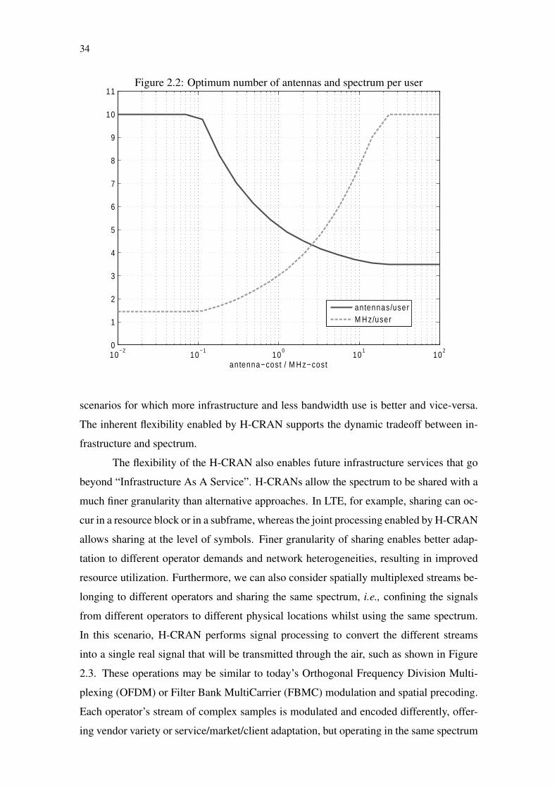
34
Figure 2.2: Optimum number of antennas and spectrum per user
scenarios for which more infrastructure and less bandwidth use is better and vice-versa.
The inherent flexibility enabled by H-CRAN supports the dynamic tradeoff between in-
frastructure and spectrum.
The flexibility of the H-CRAN also enables future infrastructure services that go
beyond “Infrastructure As A Service”. H-CRANs allow the spectrum to be shared with a
much finer granularity than alternative approaches. In LTE, for example, sharing can oc-
cur in a resource block or in a subframe, whereas the joint processing enabled by H-CRAN
allows sharing at the level of symbols. Finer granularity of sharing enables better adap-
tation to different operator demands and network heterogeneities, resulting in improved
resource utilization. Furthermore, we can also consider spatially multiplexed streams be-
longing to different operators and sharing the same spectrum, i.e., confining the signals
from different operators to different physical locations whilst using the same spectrum.
In this scenario, H-CRAN performs signal processing to convert the different streams
into a single real signal that will be transmitted through the air, such as shown in Figure
2.3. These operations may be similar to today’s Orthogonal Frequency Division Multi-
plexing (OFDM) or Filter Bank MultiCarrier (FBMC) modulation and spatial precoding.
Each operator’s stream of complex samples is modulated and encoded differently, offer-
ing vendor variety or service/market/client adaptation, but operating in the same spectrum
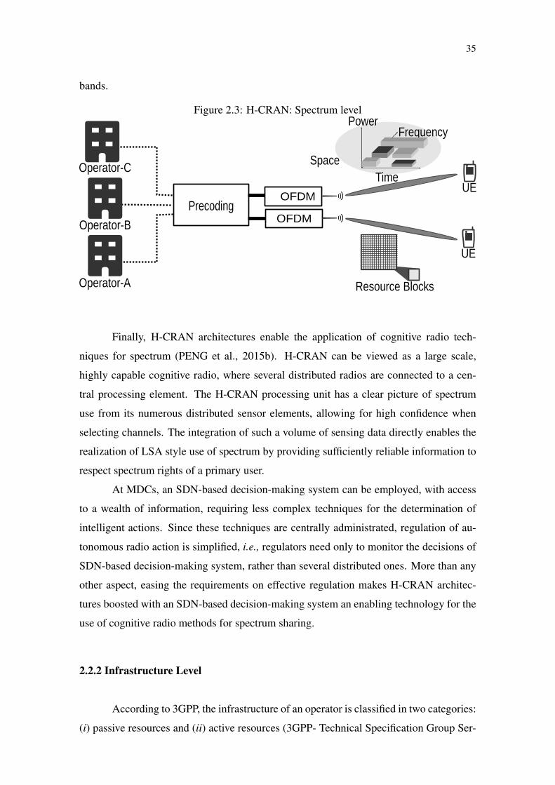
35
bands.
Figure 2.3: H-CRAN: Spectrum levelPower
Frequency
TimeSpace
Resource Blocks
UE
UE
OFDMPrecoding
OFDM
Operator-A
Operator-B
Operator-C
Finally, H-CRAN architectures enable the application of cognitive radio tech-
niques for spectrum (PENG et al., 2015b). H-CRAN can be viewed as a large scale,
highly capable cognitive radio, where several distributed radios are connected to a cen-
tral processing element. The H-CRAN processing unit has a clear picture of spectrum
use from its numerous distributed sensor elements, allowing for high confidence when
selecting channels. The integration of such a volume of sensing data directly enables the
realization of LSA style use of spectrum by providing sufficiently reliable information to
respect spectrum rights of a primary user.
At MDCs, an SDN-based decision-making system can be employed, with access
to a wealth of information, requiring less complex techniques for the determination of
intelligent actions. Since these techniques are centrally administrated, regulation of au-
tonomous radio action is simplified, i.e., regulators need only to monitor the decisions of
SDN-based decision-making system, rather than several distributed ones. More than any
other aspect, easing the requirements on effective regulation makes H-CRAN architec-
tures boosted with an SDN-based decision-making system an enabling technology for the
use of cognitive radio methods for spectrum sharing.
2.2.2 Infrastructure Level
According to 3GPP, the infrastructure of an operator is classified in two categories:
(i) passive resources and (ii) active resources (3GPP- Technical Specification Group Ser-

36
vices and System Aspects, 2014). In the former, passive resources are classified as not
computational related, such as sites, building premises, and masts (LIANG; YU, 2014).
These passive resources can be sub-leased among operators characterizing passive shar-
ing. For example, in some Brazilian cities, the deployment of new towers in some areas is
only granted when all towers in these areas have their capacity exhausted. Therefore, in
this case, the passive sharing among operators is mandatory to provide capacity without
the need for new towers. Active resources, in turn, encompasses entities that are directly
bound to the network processing, e.g., base stations, access points, backhaul, routers, and
switches. Mechanisms that abstract these entities can be used to make them accessible
from software, easing their remote management through the network (COSTA-PéREZ et
al., 2013). Such an abstraction can be performed, for example, through the use of virtual-
ization and SDN paradigms. Taking advantage of such paradigms, enables an SDN-based
decision-making system to be employed determine the best configurations to enhance
H-CRAN performance, solving bottlenecks and easing the sharing. Since passive re-
source sharing is well exploited and is already provided by third parties (COSTA-PéREZ
et al., 2013) with almost no benefits from employing an SDN-based decision-making sys-
tem, in this section we focus on active resources, which management and control enable
massive reduction of CAPEX and OPEX.
In H-CRAN different from HetNets and C-RAN, RRHs replace base stations and
access points, among other RAN devices, as depicted in Figure 2.4. Through a high
capacity backhaul based on millimeter waves and/or optical links, RRHs upload their
workload (e.g., modulation and MIMO precoding) to be computed at an MDC. Different
from a C-RAN environment that focus on macro cell workloads, in H-CRAN the huge
amount of processing workload coming from macro and small cells will eventually turn
the sharing of MDCs a need, creating MDC pools. Operator resources from macro and
small cells can be efficiently shared by having their workload optimally processed at
shared pools through Cloud-Computing-based Cooperative Radio Resource Management
(CC-CRRM) (PENG et al., 2014). For example, by centralizing the workload processing,
the pool can easily identify a macro cell as overloaded, directing users to handover to a
shared underutilized small cell from another operator (e.g., using IEEE 802.21) without
the need for additional steps to process the inter-operator handover. In this case, an SDN-
based decision-making system can be employed to determine whether a handover must
be triggered and whether a shared infrastructure can be exploited.
In a recent 3GPP technical report (3GPP- Technical Specification Group Services

37
Figure 2.4: H-CRAN: Infrastructure level
and System Aspects, 2014), different scenarios of infrastructure sharing are defined for
common cellular networks. We have remapped these scenarios to the H-CRAN context.
Next, for each remapped scenario, we present a brief description, and discuss a major open
challenge that can be alleviated by the employment of an SDN-based decision-making
system.
In the first scenario, the core of an operator is shared with other operators to han-
dle two or more RANs. In H-CRAN, the sharing of an operator core can be represented
by the MDC processing capacity being shared among different RANs. In this case, the
important decision to which MDC the workload will be sent is fundamental, which can
be determined by an SDN-based decision-making system. For instance, in Figure 2.4,
let’s suppose that MDC-B becomes overloaded by processing heterogeneous cells work-
loads from RAN-B. Therefore, MDC-B can forward its workload to be processed on the
idle MDC-A. In this scenario, a major challenge is how to share the processing capacity
among BBUs by distributing the workload without inserting more complexity. The de-
cision of workload distribution can be modeled as an optimal problem MDCs similar to,
for example, a bin packing problem (QIAN et al., 2015) considering frequency, time, and
38
space, and the container as a vBBU to be placed within an MDC that can be solved within
an SDN-based decision-making system. It means that the workload distribution is an opti-
mization problem that must be processed without compromising the MDCs to meet strict
performance requirements. For example, according to a white paper from China Mobile
Institute Research (China Mobile Research Institute, 2011), MDCs have a time restric-
tion for processing workloads of 3 ms in LTE/Long Term Evolution Advanced (LTE-A).
According to the strict performance requirements, heuristic solutions must be explored to
solve the problem of workload distribution. As a matter of fact, such strict performance
requirements must be met to turn feasible the employment of an SDN-based decision-
making system in H-CRAN.
In the second scenario, a RAN from an operator is shared with other operators
without mixing spectrum resources. In H-CRAN, the same scenario would be repre-
sented by vBBUs processing workloads from a RAN without mixing their spectrum re-
source pool. vBBUs may exploit Cloud-Computing based Cooperative Self Organization
Networking (CC-CSON) techniques to orchestrate all the RAN connected to the pool.
Using CC-CSON, the MDCs exchange information to allow subscribers from different
operators to use the same RRHs and gain access to the network. However, the isolation
of spectrum resources of each operator is kept, i.e., frequencies of both operators are not
shared. In Figure 2.4, RAN-A could have its workload divided between Operator-A and
Operator-B to be forwarded and processed by their respectively MDCs. This forwarding
can be performed directly, between MDC-A and MDC-B, or indirectly, through a Cloud
provider. In this scenario, the main open challenge is how to provide the workload ex-
change among MDCs with different vBBUs. The workload exchange requires the defini-
tion of a new interface and stack of protocols among vBBUs, whereas there already exist
interface definitions for communication between vBBUs and RRHs, such as the Com-
mon Public Radio Interface (CPRI) and the Open BBU-RRH Interface (OBRI) (China
Mobile Research Institute, 2011). Such interface can be modeled within an SDN-based
decision-making system easing the integration and workload exchanging among MDCs.
The third and fourth scenarios refer to the sharing of coverage area among oper-
ators, being performed partially and fully respectively. Partial sharing means that RANs
from different operators can be shared within a small geographic area. Full sharing, in
turn, combines RANs from different operators completely to enlarge their coverage in a
country.vBBUs within MDCs could accept access from subscribers of different operators
inside their own infrastructure to expand the coverage area. In addition, vBBUs can share

39
their workload, as well as their RANs, with other operator’s vBBUs, considering all the
entities shown in Figure 2.4. In this scenario, a partially shared H-CRAN has the chal-
lenge to provide a policy mechanism to grant permission to or restrain operators from
using other RANs. For fully shared H-CRANs, scalability becomes a major challenge be-
cause there are physical limitations to move workloads among a huge number of vBBUs
within different MDCs as well as managing them. In this case, an SDN-based decision-
making system can determine where to move a workload by employing algorithms that
solve the shortest path or minimum spanning tree problem, where MDCs represent nodes
connected by optical links that present the edges. The weight of each edge can be mea-
sured in terms of a weighted sum that considers the quantity, the delay, and the processing
time needed to process the workload being exchanged. Different solutions can be ex-
plored, for example, Dijkstra’s algorithm for shortest path or Bernard Chazelle soft heap
for spanning tree problem.
2.2.3 Network level
Integrating spectrum and infrastructure also considering that they may belong to
different operators using H-CRAN requires the careful orchestration of resources to pre-
serve bilateral agreements among operators. To this end, the state-of-the-art indicates
solutions based on the abstraction of heterogeneous physical layer to an overlay (LIANG;
YU, 2014) (COSTA-PéREZ et al., 2013) (DEMESTICHAS et al., 2013), which in this
document is called the network layer, depicted in Figure 2.5. At the network layer, phys-
ical entities are abstracted according to high level network metrics, e.g., throughput and
processing. To achieve such abstraction, we highlight four fundamental key enabling
technologies: (i) Software-Defined Radio (SDR) for Radio Frequency (RF) processing
decoupling in a software layer (China Mobile Research Institute, 2011); (ii) virtualization
for physical layer complexity abstraction and isolation (LIANG; YU, 2014); (iii) Net-
work Function Virtualization (NFV) for scalability and network functionalities isolation
(COSTA-PéREZ et al., 2013); and (iv) SDN for centralization and improved orchestra-
tion of network control and management (BERNARDOS et al., 2014) accomplishing an
SDN-based decision-making system. Below, for each of these technologies, we provide a
brief description as well as a discussion of their employment in H-CRAN and major open
challenges.
SDR refers to technologies where the baseband processing is performed by soft-

40
Figure 2.5: H-CRAN: Network level
ware modules running digital processors (China Mobile Research Institute, 2011). In
H-CRAN, the use of software modules enables the baseband processing by a software
layer in vBBUs containers placed within MDCs. As a consequence, operations, such as
coding, modulation, signal processing, and radio parameter configurations, can be easily
computed by the processing pool. Currently, an open challenge for SDR in H-CRAN is
to provide an optimal solution to split radio functionalities between RRH and vBBUs to
avoid performance degradation in terms of latency aggregation and higher energy con-
sumption (WUBBEN et al., 2014). Although the technology to split radio functionalities
is still an open research subject, their orchestration and control are likely to be solved
within an SDN-based decision-making system (BARTELT et al., 2015).
Virtualization enables network entities to have their heterogeneous physical com-
plexity abstracted to a homogeneous vBBU. Also, this technology avoids mixing work-
loads from different operators, isolating resources from the physical network in self con-
tained virtual machines or containers (DEMESTICHAS et al., 2013). In H-CRAN, BBUs
and RRHs can be virtualized in vBBUs having their physical resources (e.g., frequencies
and backhaul capacity) homogenized in higher network metrics. vBBUs can be linked,
creating an overlay network, also called network layer, as depicted in Figure 2.5. Within
a network layer, UEs that generate traffic can be represented by demand points. Network
slices can then be created to combine resources from vBBUs to meet the requirements of
demand points. However, the dynamicity of wireless environments imposes challenges
for virtualization in H-CRAN. It means that virtualization must be performed over a dy-
namic resource pool that must be frequently recalculated to guarantee the correct opera-
tion of vBBUs (LIANG; YU, 2014). Virtualization is one of the main technologies re-

41
quired to the accomplishment of an SDN-based decision-making system within H-CRAN
and, as such, could not be left without proper mapping.
NFV encapsulates network functionalities into software packages that can be dis-
tributed through the network to be performed in an homogeneous environment, for ex-
ample, a virtualized network (BERNARDOS et al., 2014). In H-CRAN, NFV provides
scalability for the sharing among operators that involves a huge number of vBBUs and
RRHs, creating large network domains (China Mobile Research Institute, 2011). NFV
also provides isolation of network functionalities by creating packages, or simply Virtual
Network Functions (VNFs), that have their execution life cycle completely independent
from others. The definition of a standard platform to manage the life cycles of VNFs is
an open challenge for the realization of NFV in H-CRAN. Although it is not the focus
of this work, in an SDN-based decision-making system, the management and chaining of
VNFs can be remapped as decisions to be made for the entire H-CRAN.
SDN has been proposed as a solution for improved orchestration of networks
(BERNARDOS et al., 2014). This orchestration is achieved through centralized con-
trollers that provide a clear separation between control and data planes. In H-CRAN, the
controller is a component of an SDN-based decision-making system hosted in an MDC
processing pools. Data flows are established as rules to be deployed among or in vBBUs,
providing rescaling of available resources without compromising the network (DEMES-
TICHAS et al., 2013). A major challenge to realize SDN in H-CRAN is the creation
of an interface that supports wireless network operations, e.g., controlling handover and
managing mobility across heterogeneous RANs, which is one of the contributions of this
work in the accomplishment of SDN-based decision-making system.
2.2.4 Trending technologies
Considering each of the different resource levels of H-CRAN, we highlight some
trending technologies that will be indispensable for the conceiving of SDN-based decision-
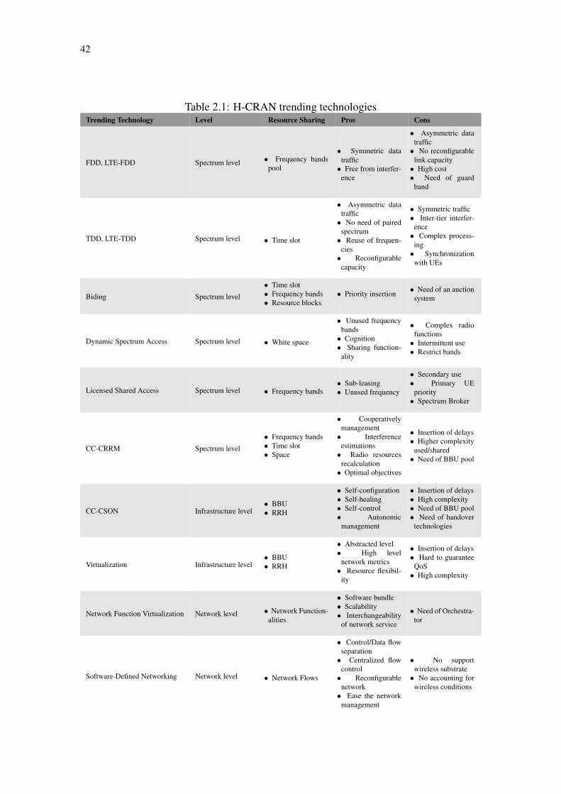
making system. In Table 2.1, we classified each technology according to the H-CRAN
level and its application. In addition, different shareable resources are also presented as
well as the Pros and Cons for each technology.
Considering Table 2.1, we can related each technology of different levels in the
conceiving of resource management and sharing in an H-CRAN that are cornerstone to
the design and implementation of an SDN-based decision-making system. One of the
42
Table 2.1: H-CRAN trending technologiesTrending Technology Level Resource Sharing Pros Cons
FDD, LTE-FDD Spectrum level • Frequency bandspool
• Symmetric datatraffic
• Free from interfer-ence
• Asymmetric datatraffic
• No reconfigurablelink capacity
• High cost• Need of guard
band
TDD, LTE-TDD Spectrum level • Time slot
• Asymmetric datatraffic
• No need of pairedspectrum
• Reuse of frequen-cies
• Reconfigurablecapacity
• Symmetric traffic• Inter-tier interfer-
ence• Complex process-
ing• Synchronization
with UEs
Biding Spectrum level
• Time slot• Frequency bands• Resource blocks
• Priority insertion • Need of an auctionsystem
Dynamic Spectrum Access Spectrum level • White space
• Unused frequencybands
• Cognition• Sharing function-
ality
• Complex radiofunctions
• Intermittent use• Restrict bands
Licensed Shared Access Spectrum level • Frequency bands• Sub-leasing• Unused frequency
• Secondary use• Primary UE
priority• Spectrum Broker
CC-CRRM Spectrum level
• Frequency bands• Time slot• Space
• Cooperativelymanagement
• Interferenceestimations
• Radio resourcesrecalculation
• Optimal objectives
• Insertion of delays• Higher complexity
used/shared• Need of BBU pool
CC-CSON Infrastructure level• BBU• RRH
• Self-configuration• Self-healing• Self-control• Autonomic
management
• Insertion of delays• High complexity• Need of BBU pool• Need of handover
technologies
Virtualization Infrastructure level• BBU• RRH
• Abstracted level• High level
network metrics• Resource flexibil-
ity
• Insertion of delays• Hard to guarantee
QoS• High complexity
Network Function Virtualization Network level • Network Function-alities
• Software bundle• Scalability• Interchangeability
of network service
• Need of Orchestra-tor
Software-Defined Networking Network level • Network Flows
• Control/Data flowseparation
• Centralized flowcontrol
• Reconfigurablenetwork
• Ease the networkmanagement
• No supportwireless substrate
• No accounting forwireless conditions

43
major features of SDN-based decision-making system resides in its capability to reconfig-
ure H-CRAN at each different level. Through CC-CRRM, SDN-based decision-making
system has the potential to exploit the shared pool of spectrum, using different regimes
and techniques, i.e., FDD, TDD, and biding, deciding whether one of them must be em-
ployed. In addition, combining CC-CRRM and SDR can enable SDN-based decision-
making system to change H-CRAN spectrum access exploiting, for instance, shared fre-
quencies bands, i.e., DSA or LSA, adapting itself to different operators policy of spectrum
access. Moreover, using CC-CSON within an SDN-based decision-making system, the
infrastructure of H-CRAN can become self-managed, which combined to virtualization
enable the integration of multi-operator infrastructures under an abstracted vBBU. For
each vBBU, NFV technology can quick distribute network services and functionalities
to be executed and supply different operators subscribers. Finally, SDN-based decision-
making system can also help in the network flows orchestration using traditional SDN
concepts to improve the performance of vBBUs intercommunication achieving QoS and
improved users experience.

44

45
3 RELATED WORK
In this chapter, we present the state-of-the-art of SDN-based decision-making sys-
tem and the H-CRAN challenges that serve as guidelines for its design. In Section 3.1,
we review different work from the literature that exploit the concept of SDN in H-CRAN
for decision-making process. Afterwards, in Section 3.2, we identify main challenges of
H-CRAN that will guide the design of a SDN-based decision-making system.
3.1 Related Work of an SDN-based decision-making system
H-CRAN become a promising scenario to accommodate high-performance ser-
vices. The interaction between RRHs and vBBUs scheduling resources among MDCs in
cloud has become more frequent and complex due to the development of scalable sys-
tem considering different user requirements translated in different QoS metrics, such as
high throughput and short delays. The heavy-duty interaction can promote the network-
ing demand among RRHs and MDCs, and forces to form elastic optical fiber switching
and optical networking according to the characteristics of high bandwidth, low cost, and
transparent multi-rate traffic transmission. In such a network, the different resource levels
of H-CRAN have to interactively be readjust through network decisions, such that a tradi-
tional architecture cannot efficiently implement the resource optimization and scheduling
for the high-level QoS guarantee. In this case, several solutions from the literature have
been proposed to exploit SDN concepts changing the decisions made within H-CRAN,
enabling programmability and centralization within its infrastructure. However, these so-
lutions present limitations and drawbacks in several aspects, such as the lack of delay
tolerance restriction and lack of proper APIs to handle H-CRAN resource levels, such as
reviewed next.
In the work of Yang et al. (YANG et al., 2016), the authors propose an architecture
for an SDN-based decision-making system for H-CRAN named Cloud-Radio over Fiber
Networking (C-RoFN). The authors claimed that their architecture can globally optimize
radio frequency, optical spectrum, and MDC processing resources effectively to maxi-
mize radio coverage and meet UEs QoS requirement. The functional modules of C-RoFN
architecture include the core elements of radio, optical, and MDC controllers. The coop-
eration procedures in multi-layer vertical integration and cross-level of resources merging
models are investigated. The overall feasibility and efficiency of the proposed architecture

46
are also experimentally demonstrated on an SDN-enabled testbed with OpenFlow-enabled
elastic optical nodes, and compared to cross-stratum optimization strategy in terms of re-
source allocation and path provisioning latency. Although the closest work to this thesis,
the authors proposed C-RoFN without considering that H-CRAN is delay intolerant. It
means that the decision making procedure is taken without considering the delay budgets
mainly inherited from wireless network processing that can compromise the operation of
an H-CRAN. For instance, the authors did not consider the delay budget imposed by the
Hybrid Automatic Repeat reQuest (HARQ) mechanism that can easily compromise the
allocation of processing resources and migration within the cloud. Also, their solution
only considers the decisions taken for a snapshot of the H-CRAN status, being unable to
have its performance measured during runtime. Different than that, our work address the
issue of delay intolerance and support operations of H-CRAN during runtime.
In the work of Liang et al. (LIANG et al., 2017), an integrated architecture based
on SDN is proposed to decouple the control plane from the data plane to provide net-
work programmability, and virtualization such that network and radio resources can be
shared among several applications. The authors also considered the potential of dis-
tributed MDCs as fog computing to offload services from the cloud to the edge of net-
works, offering real-time data services to nearby data terminals. The authors design an
architecture of an SDN-based decision-making system considering concepts of software
as a service called OpenPipe, which enables network level virtualization. To integrate
SDN and network virtualization with fog computing, the authors adopt a hybrid control
model with two hierarchical control levels, where an SDN controller forms the higher
level and local controllers comprise the lower level. These two hierarchical levels dif-
ferentiate the controllers responsibilities, e.g., radio resource management and resource
sharing, as an architecture decision. Instead, the decisions of where and which responsi-
bilities should be placed and executed within an H-CRAN should be taken by a network
administrator, engineer or operator, programmaticaly at SDN’s application level to meet
their infrastructure requirements leaving the control plane homogenized such as proposed
in this work.
In the work of Yuan Zhang, Ying Wang, and Bo Fan (ZHANG; WANG; FAN,
2017), the authors investigate an energy efficient resource allocation scheme for uplink
H-CRAN considering an SDN-based decision-making system. The authors analyze the
information from the data plane of an RAN, and execute the resource allocation process in
the control plane. In the control plane, a relay region decision algorithm is designed and
47
placed on top of an SDN controller to reduce the computational complexity after another
algorithm perform UEs classification. Afterward, an optimal power allocation decision
algorithm perform relay and network selection decisions considering the total power con-
straint, quality of service requirements, and radio resource constraints aiming to maximize
spectral efficiency. Although the work sheds light on interdependency among decision al-
gorithms for a SDN-based decision-making system, the authors did not consider delay
constraints that can easily hinder signal processing preventing the decisions to be taken
without compromising the H-CRAN performance.
In the work of Selim et al. (SELIM et al., 2016), the authors propose an SDN-
based decision-making system to handle the self-healing procedures of an H-CRAN.
A novel cell outage compensation approach using SDN added to each cell site in the
H-CRAN to detect network failure of any RRH or compromised optical link at fronthaul.
The authors advocate that node failure means the loss of hundreds of gigabits, or even
terabits for an H-CRAN. The authors also introduces a high-level simulation study that
is carried out to assess the proposed approach resulting in gains expressed in degree of
recovery from node failures. In this work, delay constraints are not considered. Also,
during the self-healing execution it is not clear how a distributed cloud containing MDCs
spread along the pool are reconfigured when stricken by node failure.
Considering each of the aforementioned work it becomes clear that although the
proposal of an SDN-based decision-making system is not novelty by itself, its design is
still vague for an H-CRAN. Delay constraints can easily prejudice the decisions taken
by an SDN-based decision-making system since MDC can have their signal processing
compromised for delay intolerable wireless mechanisms, such as HARQ. Despite delay
constraints, in H-CRAN, the cloud, fronthaul, and RAN are infrastructures that require
different decisions to be taken in a homogenized control plane. The homogenized con-
trol plane enable controller to quickly adapt to the different infrastructures under con-
trol. In this case, we investigate different research question which are raised based on
the literature. For instance, What challenges can an SDN-based decision-making system
solve in H-CRAN? What responsibilities can an SDN-based decision-making system as-
sume in H-CRAN? Can SDN-based decision-making system be used considering delay
constraints? How an SDN-based decision-making system will perform during H-CRAN
operation? To solve these different research questions, we start by identifying main chal-
lenges of an H-CRAN that will serve as motivation and guidelines for the design of an
SDN-based decision-making system, such as provided next.

48
3.2 H-CRAN Challenges
Considering the resource levels of an H-CRAN, we selected three of the main
challenges identified: (i) high intercell interference at spectrum level; (ii) critical delay
constraints in long-distance wireless signal processing at infrastructure level; and (iii)
poor processing power allocation at network level. In the first, a high number of UEs are
connected to several RRHs at the RAN to consume applications and services with high
QoS requirements in terms of small delays, high throughput, and transparent mobility, that
cannot afford capacity loss due to interference requiring sharing (MAROTTA et al., 2015).
In the second, the fronthaul that interconnects the RAN and the pool must be able to
forward the workload from RRHs to the MDC within stringent delay budgets (MAROTTA
et al., 2018a). In the third, the cloud, in turn, is composed of MDC with several GPP
that must be allocated to avoid processing power underusage for long term operation.
Considering the H-CRAN levels and its main parts divided in RAN, fronthaul, and cloud
different requirements emerge that must be met according to decisions that must be taken.
In this regard, we present the literature for highlighting the decisions that must be taken
in H-CRAN targeting the aforementioned challenges that will serve as guidelines for the
design of an SDN-based decision-making system.
3.2.1 High Intecell Interference
In the RAN, UEs and RRHs are connected through licensed portion of the spec-
trum of an operator. Given that the licensed spectrum is a finite and expensive resource,
algorithms must manage all the radio resource to improve spectrum usage. Managing ra-
dio resources comprises all the allocation, coordination, and maintenance of the resources
used inside a RAN that are related to the creation of radio links. In this case, different de-
cision algorithm are proposed in the literature to enhance the spectrum usage in H-CRAN.
In the work of Peng et al. (PENG et al., 2015b), a decision algorithm is proposed
based on contract game theory to reduce interference. The authors proposed an algo-
rithm to execute decision of spectrum allocation sitting on top of a centralized cloud used
in a simulated H-CRAN scenario. In this scenario, spectrum frequencies that are shared
among all cells considering RRHs spread along an LTE E-UTRAN Node B (eNB) macro-
cell coverage area. For each interaction in the system, a contract proposal is created per
association of UE and RRH regarding the spectrum frequencies to be used and how much

49
interference the transmission will create for other communications. The authors claim that
contracts are accepted or not by a centralized decision system that identifies the best pro-
posals with the smaller interference and best spectrum efficiency for the whole H-CRAN
converging to an equilibrium. In this case, all the decisions are based on the SNR sensed
by the RRH of a snapshot of the network focused on spectrum efficiency and interference
minimization disregarding other requirements such as users mobility or QoS guarantees.
In the work of Lee, Loo, and Chuah (LEE; LOO; CHUAH, 2016), the sharing
of resources is introduced as a solution for interference coordination involving different
network operators. The authors modeled a decision algorithm able to optimize the inter-
ference cancellation of an H-CRAN with a centralized cloud considering sharing of re-
sources. Although the algorithm shed lights on the usage of sharing in H-CRAN, the only
resource considered is the spectrum disregarding the infrastructure and its requirements.
Whereas, Panchal et al. (PANCHAL; YATES; BUDDHIKOT, 2013) stated that resource
sharing can be divided in capacity, spectrum, and infrastructure. In their work, capac-
ity is a quantitative measurement with respect to the number of subscribed and roaming
UE to be served in a RAN. This measurements is classified as an inter-operator roam-
ing relationship whereas the other resources remain with the same definition. The authors
also defined three types of participants that must be considered during decisions revolving
spectrum sharing: (a) operators (e.g., Verizon and AT&T), (b) third parties, i.e., infras-
tructure owners (not operators) or brokers of cellular resources (e.g., a TV operator), and
(c) service/content providers (e.g., NetFlix) that lease resource from operators and third
parties to serve users with improved QoS.
Three distinct sharing scenarios are proposed in Panchal et al. (PANCHAL; YATES;
BUDDHIKOT, 2013) to each participant considering different decisions to be made such
as follows: (i) inter-operator resource sharing, (ii) operators that lease resource from third
parties, and (iii) resource exchange among all the participants. The authors defined an
architecture to support all the different types of resource sharing relationship and the nec-
essary decisions to be made. This architecture divides the decision process in four tasks
to perform eICIC and resource sharing:
• Configuration that accounts for topological information stored in databases;
• Decision & condition a mechanism that decide which resource should be shared/al-
located according to a Key Performance Indicator (KPI) (e.g., SNR, spectral usage,
traffic loading, or co-channel interference) and the sharing agreements established
in terms of time, space, spectrum, service, interference, and cost;
50
• Coordination, negotiation & management through a shared database, sharing part-
ners are identified according to the matched resource needed establishing a rela-
tionship of one-to-one, one-to-many, or many-to-many; and
• Activation, deactivation, & reactivation related to the execution of the established
relationship from the previous tasks, all the RAN shall reconfigure themselves to
fulfill their duties according to the sharing agreements defined.
As in Panchal et al. (PANCHAL; YATES; BUDDHIKOT, 2013), Kibilda et al.
(KIBILDA et al., 2015) conducted an investigation determining the need to integrate re-
sources sharing and coordination from infrastructure to spectrum to solve the problem
of eICIC and resource allocation. Lin et al. (LIN et al., 2010) advocates that compared
to infrastructure-based cooperation, spectrum-based cooperation avoids the overhead of
tight inter-operation among sharing operators involved, which is a resource sharing model
inside dynamic spectrum management. Their spectrum-based sharing proposal defines
service provisioning associated with cooperation among operators in the form of spec-
trum resource exchange decisions: while each operator has its own deployed infrastruc-
ture (including multiple base stations) and operating spectrum, they can cooperate with
each other to share their spectrum in the form of time portions to cancel interference.
Luoto et al. (LUOTO et al., 2015) proposed sharing of resource blocks among base
stations from different operators to solve eICIC at infrastructure level, where different
eNB must be assigned to synchronize their operations to cooperate. The authors also
defined different approaches for sharing resource blocks, defined according to different
decisions based on statistics metrics, using adaptation to channel conditions (i.e., SNR),
clustering, and connection availability. In the first, the decision system tries to reach a
business model assuming biased random variables for defining the cost of the information
used. In the second, given the proposed business model, the system must assure that every
node respect the decisions taken equally. In the third, a neighborhood of eNBs is created,
balancing the resource shared among them, aiming for resource optimization inside the
evaluated area. Finally, a distributed decision algorithm is used to consider any connection
among BSs according to their control plan being linked, exchanging information and
sharing their spectrum.
Gerasimenko et al. (GERASIMENKO et al., 2015), in turn, propose a cross-cell
radio resource allocation decision algorithm for eICIC in H-CRAN. Instead, in the work
of Peng et al. (PENG et al., 2014), the authors identify timescale subproblems that must
be solved in different periods, i.e., (i) long timescale subproblem and (ii) short timescale

51
subproblem. In the first, routing, UE scheduling, and association are examples of long
timescale problems that can be solved within a larger time window considering the Queue
State Information (QSI) statistics. Whereas, in the second, power and rate allocation as
well as MIMO beamforming and antenna selection are short time scale subproblem to be
solved within H-CRAN that must rely on the instantaneous Channel State Information
(CSI) and gathered SNR measurement.
In the aforementioned work, the authors claim that their systems and algorithms
are able to determine the best decisions to improve UEs and RRHs capacity through re-
source sharing achieving eICIC for different timescale subproblem. As a drawback, the
presented work assumes perfect dimensioning of the fronthaul and processing resource
allocation in the cloud incurring no delays or processing outage. In practice, this assump-
tion is not realistic due to extra delay incurred by remote processing in H-CRAN, which
is better characterized next. Another important detail identified is that the most used
information during the decision process at the spectrum level is the channel condition
expressed in SNR.
3.2.2 Critical delay constraints in long distance wireless signal processing
In an H-CRAN, remote processing is performed between MDC and RRH requir-
ing the workload to traverse either wireless (e.g., millimeter wave fronthaul (DAT et al.,
2014)) or optical infrastructures (BARTELT et al., 2015) incurring delays. The delay oc-
curring at the fronthaul is later summed to the workload processing time at the MDC com-
posing the round-trip delay. According to a white paper of China Mobile (China Mobile
Research Institute, 2011), the round-trip delay cannot surpass a threshold of fewer mil-
liseconds to perform remote processing of the radio protocol. For instance, LTE present
a round-trip delay budget around 3 ms. Considering this limitation, the distance between
MDC and RRH becomes limited to fewer tens of kilometers, more specifically, around 20
km.
In another study, Bhaumik et al. (BHAUMIK et al., 2012) proposed a framework
based on a trace of measurements gathered from an operational Wideband Code Divi-
sion Multiple Access (WCDMA) telecommunication network to analyze the round-trip
delay and how it influences remote processing. In this work both downlink and uplink
of a WCDMA were evaluated. For downlink, the encoding, modulation, and scrambling
functions’ execution time were measured allowing the authors to conclude that the time

52
involved to process the whole radio protocol increases according to the processing time
of the encoder in use. Whereas for the uplink, the decoding, the Fast Fourier Trans-
form (FFT) algorithm, and the demodulation were measured in terms of execution time.
For the uplink processing, the authors concluded that the decoding execution time excels
all other functions, influencing the whole radio protocol execution’s performance. When
considering both, downling and uplink, the execution time increases accordingly to the
uplink decoder function complexity. Based on this conclusions, we also investigate the
Forward Error Correction (FEC) giving higher attention to the decoding function when
determining the decisions to be taken in our work.
Further, Liu et al. (LIU et al., 2015) proposed a graph-based framework for split-
ting the radio protocol function, e.g., decoding, FFT, and modulation, among MDC. This
work sheds light on the need to account for delay when distributing the processing of the
radio protocol within a pool of many MDCs. The resulting graph considers the compu-
tational cost of each function as nodes biased according to delay results obtained from
(BHAUMIK et al., 2012). Their proposed model focused on the tradeoff between pro-
cessing delay and fronthaul costs without a detailed analysis of each radio function nor
the MDC pool and RAN performance improvements. Instead, the authors focused their
research into deciding the best division of functions within a set of MDCs.
Alyafawi et al. (ALYAFAWI et al., 2015), in turn, propose the implementation of a
remote processing environment to support the virtualization of eNB from LTE (3rd Gen-
eration Partnership Project (3GPP), 2015). In this environment, the authors suggested
through the calculation of the total latency of an eNB that process channel coding and
decoding are major responsible for processing outage and delay violation. Both func-
tionalities hinder the virtualization of the LTE radio protocol due to the processing delay
imposed by both. The authors suggest good manners to decrease the latency by using
real time virtualization, they also presented an analysis of the hypervisors gains when
used in different situations. In addition, the authors proposed a upper bound equation for
defining the cycle capacity needed for C-RAN processor to cope with the worst case sce-
narios of LTE in a remote processing scenario, such as H-CRAN. The authors, however,
considered a fully centralized scenario with almost zero latency fronthaul, which is not
physically possible.
In the work of Musumeci et al. (MUSUMECI et al., 2016), an assignment prob-
lem is modeled for a distributed MDC scenario, where decisions are made to determine
the best match between MDC and RRHs such that energy gains can be enhanced. The as-
53
signment problem considered optical links with constrained capacity that transport limited
number of workloads from RRHs to MDCs having to distribute it without compromising
the fronthaul considering a limited distance between MDC and RRH regarding delay con-
straints. In this case, the authors focused their work in the high bit-rate fronthaul traffic
also considering that the RRHs workload must be transported over the existing aggrega-
tion network, i.e., it shall be multiplexed and/or routed and integrated to the conventional
backhaul traffic.
Delay constraints dictate the assignment between MDC and RRH within the pool
to distribute processing, which impacts directly in the maximum distance afforded be-
tween MDC and RRHs. The major drawback of the presented literature lies in the as-
sumption that delay is fixed as it is purely technology dependent, which, in fact, is not
completely true, since the decoding function has to adapt the number of recursions ac-
cording to channel conditions varying the processing delay occurring (BREJZA et al.,
2016). Taking advantages of the fluctuation of the processing delay enables to create a
new tradeoff involving distance between MDC and RRH and processing power changing
the assignment decision. This tradeoff is not exploited in the literature characterizing a
gap in the investigations so far. Considering the aforementioned, the delay budget of the
technology in use and also the distance between an MDC and RRH are crucial to perform
assignment decisions in H-CRAN.
3.2.3 Poor processing power allocation
The usage of processing resources brings a clear gain in terms of scalability and
energy consumption reduction (TANG; TAY; QUEK, 2015). In this case, MDCs must
be allocated and reused by several RRHs until exhaustion of their processing resources
preventing overload or underusage.
In Tang et al. (TANG et al., 2017), a joint vBBU activation and sparse beamform-
ing problem is modeled to minimize the system cost. This cost is based on a vBBU cost
(w.r.t. the energy spent with the number of active vBBU) in the MDC pool and the RRH
cost (w.r.t. the beamformer vectors). In this work, the minimization problem is split in two
subproblems, namely: fronthaul capacity optimization subproblem and a minimization of
active vBBUs. In the first, the authors proposed a price adjusting decision algorithm to
avoid overload in the limited fronthaul capacity of an H-CRAN. In the second, the opti-
mal number of vBBUs is found through two different algorithms, an integer search and a

54
joint optimization. Both subproblems were solved through simulations, in which the pro-
posed decision algorithms presented better performance and lower system cost than the
benchmark from (DAI; YU, 2014). The work of Tang et al. (TANG et al., 2017) presents
a clear allocation of processing resources within a distributed pool. The major drawback
identified on this work is the lack of a mechanism to continually allocate each vBBU in
use being unable to be used for long term operation of an H-CRAN.
In the work of Bhaumik et al. (BHAUMIK et al., 2012), the processing power
is distributed according to the availability of processors until all RRHs workloads are
processed. Consuming processors require a very narrow time scale decision. In this
regard it is not scalable for very large geographically distributed clouds.
Instead in Carapellese et al. (CARAPELLESE; TORNATORE; PATTAVINA,
2014), the authors considered that the geographical positioning of vBBUs are different. In
this case the processing power allocation becomes a placement problem within H-CRAN.
Under the network and topology perspective, the processing power allocation decision
can be analyzed as a tradeoff between the most powerful MDC and the most fitted optical
connectivity to be used, deciding the number of wavelength in use, their capacity, and
number of hops, such as presented in the work of Musumeci et al. (MUSUMECI et al.,
2016). Both work make decisions of processing power allocation for a snapshot of the
network without considering the continuous usage of it.
It is also worthy mentioning that solutions from context of cloud computing con-
sider migrations to enhance elasticity between datacenters to balance their usage and
achieve energy gains to decrease costs (RIGHI et al., 2016). Similarly, in an H-CRAN
assignment problem, the usage of migration has the objective to enhance reuse within the
pool decreasing the total processing power in use. However, the different stimuli from
the RAN summed to strict delay budgets imposed by wireless mechanisms change com-
pletely the migration execution within an H-CRAN compromising the usage of already
well established solutions from cloud computing without redesigning.
To the best of our knowledge, all the current viewpoints of the vBBU allocation
and reuse problem consider that an RRH workload can change its destiny among MDCs
within the pool every time a new assignment is performed without considering the cost
in delays to perform such migration. In fact, this migration changes the delay occur-
ring, which if not carefully accounted may hazard the connectivity between RRH and UE
causing unexpected signal intermittent and disconnections (WANG et al., 2013).
55
3.2.4 Identified gaps
Although different problems in H-CRAN are investigated in the work of (BHAU-
MIK et al., 2012), (CARAPELLESE et al., 2013), (WANG et al., 2013), (CARAPELLESE;
TORNATORE; PATTAVINA, 2014), (TANG; TAY; QUEK, 2015), (MUSUMECI et al.,
2016), and (TANG et al., 2017), we focus our attention to the following gaps identified in
the literature:
• RAN resources must be reused to enhance spectral efficiency increasing interfer-
ence. In this case, spectrum and infrastructure sharing with other operators become
fundamental to reduce interference bring spectrum efficiency benefits for all the
involved operators. However, current models are still not adapted to be used in
H-CRAN without a proper architecture to host decision algorithms to reduce inter-
ference and share resources.
• Different factors can influence the delay occurring in H-CRAN that may change
completely the usage of resources in different levels. A proper classification and
characterization of each of these factors is missing as well as a quantization of this
tradeoff for decision process enhancement.
• The H-CRAN assignment problem is usually solved for off-line instances of the
network, where snapshots of the status of the cloud, fronthaul, and RAN are used to
calculate the optimal allocation of processing resources. However, the dinamycity
of the RAN can easily outdate the decision made leading to unnecessary consump-
tion of resources.
Joining these gaps enable to identify the need of a decision system sufficiently
generic to be deployed in H-CRAN able to address these gaps altogether. However, how to
design a decision-making system able to address the different gaps identified in H-CRAN?
To answer this question, we propose the design of an SDN-based decision-making
system able to minimize interference and decrease processing power consumption con-
sidering delay constraints. This system inherits SDN concepts able to host decision algo-
rithms and interact with different resource levels to address the presented gaps. For this
purpose, in the next chapter, we first model an H-CRAN identifying and characterizing
cornerstone factors that must be taken in consideration to later propose such a system.

56

57
4 SYSTEM MODEL
In this chapter, before introducing our SDN-based decision-making system, we
must formalize H-CRAN meaningful information that will be key to solve the challenges
identified in the previous chapter using decision algorithms. For each of the identified
challenges, we modeled a subsection, such as follows: interference reduction with re-
source sharing in H-CRAN in Subsection 4.2.1; maximum distance between MDC and
RRH under delay considerations in Subsection 4.2.2; and processing power underusage
in H-CRAN in Subsection 4.2.3.
To ease the reading of this chapter, we present all notation used in Table 4.1. We
use calligraphy letters to represent sets, boldface lower case letters to denote vectors and
boldface uppercase letters to denote matrices. The notation || · ||2 stands for the Euclidean
norm, while (·)T and (·)H are the transpose and the conjugate transpose, respectively. We
use N, C and R to represent the natural numbers, complex numbers, and real numbers,
respectively. The notation A\B denotes the set A with its subset B removed. bxc stands
for the largest integer smaller than or equals x and dxe stands for the smallest integer larger
than or equals x. We use ℜ(·) and ℑ(·) as functions to extract the real and imaginary part
of a complex number, respectively.
4.1 Modeling an H-CRAN
In H-CRAN, BSs are replaced by RRHs: signal samples are digitized, transmitted
through an optical infrastructure, and remotely processed in cloud MDCs, which house
vBBUs (PENG et al., 2015a), such as depicted in Figure 4.1. Remote processing enables
H-CRANs to exploit the processing capacity available in the cloud, as well as to achieve
load balancing and reuse of processing resources (MUSUMECI et al., 2016).
An H-CRAN is composed of s ∈ S = {1,2, · · · ,S} MDCs responsible for the
remote processing of the workload of m ∈M = {1,2, · · · ,M} RRHs that are serving
n∈N = {1,2, · · · ,N}UEs. We consider that UEs communicate using MIMO with {T x∈
N | T x≥ 1} transmit antennas to an RRH that has {Rx ∈ N | Rx≥ 1} receiving antennas.
Each UE n performs a request rn that comprises a finite horizon with transmission start
time t0n and end time t f
n to transmit a certain quantity of bits ln considering that a target
BER qn must be guaranteed. Thus, for the nth UE, its request is presented as the quadruple
rn = {t0n , t
fn , ln,qn}. All requests rn ∈R = {r1,r2, · · · ,rN} of the C-RAN must be served
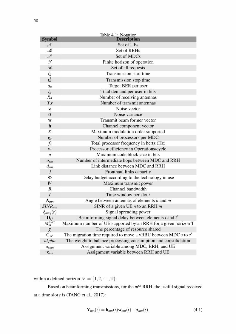
58
Table 4.1: NotationSymbol Description
N Set of UEsM Set of RRHsS Set of MDCsT Finite horizon of operationR Set of all requestst0n Transmission start time
t fn Transmission stop time
qn Target BER per userln Total demand per user in bitsRx Number of receiving antennasT x Number of transmit antennasz Noise vectorσ Noise variancew Transmit beam former vectorh Channel component vectorX Maximum modulation order supportedgs Number of processors per MDCfs Total processor frequency in hertz (Hz)vs Processor efficiency in Operations/cycleu Maximum code block size in bits
osm Number of intermediate hops between MDC and RRHdsm Link distance between MDC and RRH
j Fronthaul links capacityΦ Delay budget according to the technology in useW Maximum transmit powerB Channel bandwidthI Time window per slot t
Amn Angle between antennas of elements n and mSINRmn SINR of a given UE n to an RRH mξmn j(t) Signal spreading power
Di j Beamforming signal delay between elements i and i′
Mmaxm Maximum number of UE supported by an RRH for a given horizon Tχ The percentage of resource shared
Css′ The migration time required to move a vBBU between MDC s to s′
al pha The weight to balance processing consumption and consolidationasmn Assignment variable among MDC, RRH, and UEκmn Assignment variable between RRH and UE
within a defined horizon T = {1,2, · · · ,T}.
Based on beamforming transmissions, for the mth RRH, the useful signal received
at a time slot t is (TANG et al., 2017):
Ymn(t) = hmn(t)wmn(t)+ zmn(t). (4.1)
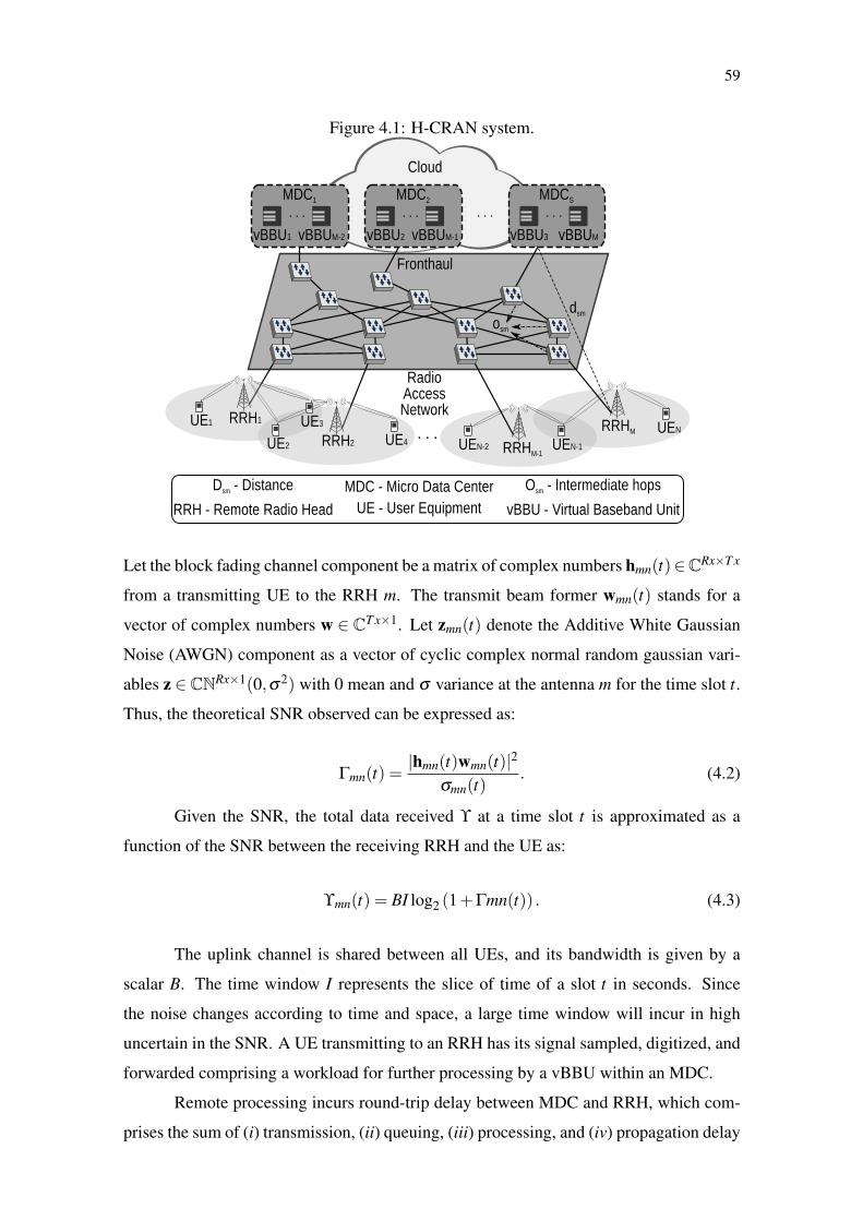
59
Figure 4.1: H-CRAN system.
Let the block fading channel component be a matrix of complex numbers hmn(t)∈CRx×T x
from a transmitting UE to the RRH m. The transmit beam former wmn(t) stands for a
vector of complex numbers w ∈ CT x×1. Let zmn(t) denote the Additive White Gaussian
Noise (AWGN) component as a vector of cyclic complex normal random gaussian vari-
ables z ∈ CNRx×1(0,σ2) with 0 mean and σ variance at the antenna m for the time slot t.
Thus, the theoretical SNR observed can be expressed as:
Γmn(t) =|hmn(t)wmn(t)|2
σmn(t). (4.2)
Given the SNR, the total data received ϒ at a time slot t is approximated as a
function of the SNR between the receiving RRH and the UE as:
ϒmn(t) = BI log2 (1+Γmn(t)) . (4.3)
The uplink channel is shared between all UEs, and its bandwidth is given by a
scalar B. The time window I represents the slice of time of a slot t in seconds. Since
the noise changes according to time and space, a large time window will incur in high
uncertain in the SNR. A UE transmitting to an RRH has its signal sampled, digitized, and
forwarded comprising a workload for further processing by a vBBU within an MDC.
Remote processing incurs round-trip delay between MDC and RRH, which com-
prises the sum of (i) transmission, (ii) queuing, (iii) processing, and (iv) propagation delay

60
components. Transmission delay at each intermediate node between MDC and RRH can
be expressed as the ratio of the number of bits sent to the capacity of the outgoing link.
Queuing delay is due to buffering the data at intermediate nodes. The vBBU within an
MDC performs processing for signal demodulation, radio resource demapping, and pre-
coding: the largest component of the processing delay is due to FEC (BHAUMIK et al.,
2012). Finally, propagation delay is given by the ratio of the distance between BBU and
RRH to the speed of the signal transmitted in the link.
The round-trip delay components are depicted in the sequence diagram in Figure
4.2.
In the vBBU, the decoding function of the FEC dominates the processing de-
lay (BHAUMIK et al., 2012) characterizing the processing workload, such as:
Ψmn(t) = ωϒmn(t). (4.4)
Given that most FEC algorithms for telecommunications have linear complex-
ity (HOLMA; TOSKALA, 2009), ω stands for a scalar value in operations/bit. The FEC
is processed for the total of data received of all RRHs associated to the UE n processed
at the MDC s. As an H-CRAN inherits C-RAN concepts of cloud systems, MDCs must
be able to process the communication from the RRHs to serve all UEs. In this case, a
vBBU is created per UE that must be allocated within an MDC s ∈ S = {1,2, · · · ,S}
composed of several GPP gs with ceiling processing power fs Hz and efficiency vs op-
erations/cycle. These vBBUs are allocated to process wireless workloads (Ψ) from UEs
(n ∈ N) connected.
The workload, comprising a set of in-phase and quadrature sample components,
potentially traverses multiple hops between the RRH and the MDC. At each hop, trans-
mission and queuing delay may be incurred to forward the sampled signal across the
network. Afterward, the vBBU sends a reply back to the UE. On the way from RRH to
MDC, the workload traverses optical links, incurring propagation delay. The propagation
delay for a fiber optic link is equal to:
γsm =3dsm
2c; (4.5)
where dsm stands for the total distance in meters between MDC and RRH, and c represents
the speed of light.
Further delay is added when an intermediate node has to transmit/receive and en-
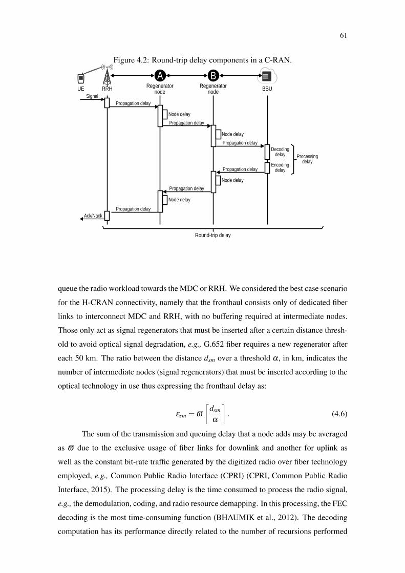
61
Figure 4.2: Round-trip delay components in a C-RAN.
BBURRH Regeneratornode
SignalPropagation delay
Decodingdelay
Encodingdelay
Ack/Nack
Processingdelay
Round-trip delay
Node delay
Propagation delay
Node delay
Propagation delay
Propagation delay
Node delay
Propagation delay
Node delay
Propagation delay
BARegenerator
nodeUE
queue the radio workload towards the MDC or RRH. We considered the best case scenario
for the H-CRAN connectivity, namely that the fronthaul consists only of dedicated fiber
links to interconnect MDC and RRH, with no buffering required at intermediate nodes.
Those only act as signal regenerators that must be inserted after a certain distance thresh-
old to avoid optical signal degradation, e.g., G.652 fiber requires a new regenerator after
each 50 km. The ratio between the distance dsm over a threshold α , in km, indicates the
number of intermediate nodes (signal regenerators) that must be inserted according to the
optical technology in use thus expressing the fronthaul delay as:
εsm = ϖ
⌈dsm
α
⌉. (4.6)
The sum of the transmission and queuing delay that a node adds may be averaged
as ϖ due to the exclusive usage of fiber links for downlink and another for uplink as
well as the constant bit-rate traffic generated by the digitized radio over fiber technology
employed, e.g., Common Public Radio Interface (CPRI) (CPRI, Common Public Radio
Interface, 2015). The processing delay is the time consumed to process the radio signal,
e.g., the demodulation, coding, and radio resource demapping. In this processing, the FEC
decoding is the most time-consuming function (BHAUMIK et al., 2012). The decoding
computation has its performance directly related to the number of recursions performed
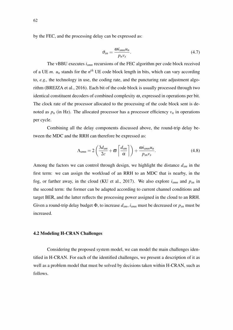
62
by the FEC, and the processing delay can be expressed as:
ϑsn =ωismnun
pnvs. (4.7)
The vBBU executes ismn recursions of the FEC algorithm per code block received
of a UE m. un stands for the nth UE code block length in bits, which can vary according
to, e.g., the technology in use, the coding rate, and the puncturing rate adjustment algo-
rithm (BREJZA et al., 2016). Each bit of the code block is usually processed through two
identical constituent decoders of combined complexity ω , expressed in operations per bit.
The clock rate of the processor allocated to the processing of the code block sent is de-
noted as pn (in Hz). The allocated processor has a processor efficiency vn in operations
per cycle.
Combining all the delay components discussed above, the round-trip delay be-
tween the MDC and the RRH can therefore be expressed as:
Λsmn = 2(
3dsm
2c+ϖ
⌈dsm
α
⌉)+
ωismnun
psnvs. (4.8)
Among the factors we can control through design, we highlight the distance dsm in the
first term: we can assign the workload of an RRH to an MDC that is nearby, in the
fog, or farther away, in the cloud (KU et al., 2017). We also explore ismn and psn in
the second term: the former can be adapted according to current channel conditions and
target BER, and the latter reflects the processing power assigned in the cloud to an RRH.
Given a round-trip delay budget Φ, to increase dsm, ismn must be decreased or psn must be
increased.
4.2 Modeling H-CRAN Challenges
Considering the proposed system model, we can model the main challenges iden-
tified in H-CRAN. For each of the identified challenges, we present a description of it as
well as a problem model that must be solved by decisions taken within H-CRAN, such as
follows.
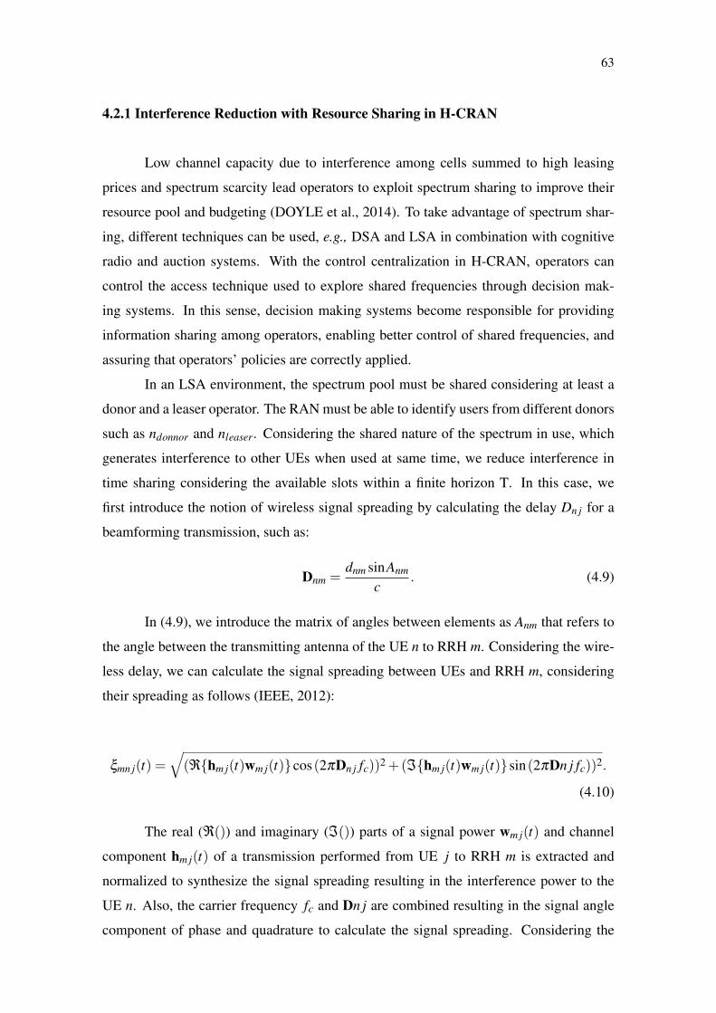
63
4.2.1 Interference Reduction with Resource Sharing in H-CRAN
Low channel capacity due to interference among cells summed to high leasing
prices and spectrum scarcity lead operators to exploit spectrum sharing to improve their
resource pool and budgeting (DOYLE et al., 2014). To take advantage of spectrum shar-
ing, different techniques can be used, e.g., DSA and LSA in combination with cognitive
radio and auction systems. With the control centralization in H-CRAN, operators can
control the access technique used to explore shared frequencies through decision mak-
ing systems. In this sense, decision making systems become responsible for providing
information sharing among operators, enabling better control of shared frequencies, and
assuring that operators’ policies are correctly applied.
In an LSA environment, the spectrum pool must be shared considering at least a
donor and a leaser operator. The RAN must be able to identify users from different donors
such as ndonnor and nleaser. Considering the shared nature of the spectrum in use, which
generates interference to other UEs when used at same time, we reduce interference in
time sharing considering the available slots within a finite horizon T. In this case, we
first introduce the notion of wireless signal spreading by calculating the delay Dn j for a
beamforming transmission, such as:
Dnm =dnm sinAnm
c. (4.9)
In (4.9), we introduce the matrix of angles between elements as Anm that refers to
the angle between the transmitting antenna of the UE n to RRH m. Considering the wire-
less delay, we can calculate the signal spreading between UEs and RRH m, considering
their spreading as follows (IEEE, 2012):
ξmn j(t) =√
(ℜ{hm j(t)wm j(t)}cos(2πDn j fc))2 +(ℑ{hm j(t)wm j(t)}sin(2πDn j fc))2.
(4.10)
The real (ℜ()) and imaginary (ℑ()) parts of a signal power wm j(t) and channel
component hm j(t) of a transmission performed from UE j to RRH m is extracted and
normalized to synthesize the signal spreading resulting in the interference power to the
UE n. Also, the carrier frequency fc and Dn j are combined resulting in the signal angle
component of phase and quadrature to calculate the signal spreading. Considering the

64
signal spreading formula, the Signal-to-Interference-plus-Noise Ratio (SINR) function
can be created among the connected UEs, such as follows:
SINRmn(t) =|hmn(t)wmn(t)|2
σmn(t)+∑N{ j∈N| j 6=n}κm j(t)ξmn j(t)
. (4.11)
In (4.11), we introduce an association binary variable κmn(t), such that:
κmn(t) =
1 i f UE n is transmitting to RRH m at slot t
0 otherwise.
Associating each UE to a shared RRH enables the system to decrease interference until
achieve resource depletion. Such depletion is characterized per RRH as the maximum
number of UEs supported Mmaxm during a horizon T. As such, to achieve minimum inter-
ference, we can model the following optimization problem per RRH:
max∀m
T
∑t
(χ
N\Ndonnor
∑nleaser
κmnleaser(t)SINRmnleaser +(1−χ)N\Nleaser
∑ndonnor
κmndonnor(t)SINRmndonnor
)(4.12)
s.t.N
∑n
κmn(t)≤Mmaxm ∀m ∈M;∀t ∈ T. (4.13)
In this optimization, we seek the maximization of the overall SINR per RRH in
(4.12). As the system must respect sharing policies, we consider that infrastructure and
spectrum are shared partially represented by the parameter χ , where {χ ∈R | 0≤ χ ≤ 1}.
The SINR is maximized for the finite horizon T as long as the constraint (4.13) of the
maximum number of UE supported Mmaxm holds. The variables κmn(t) represent the as-
sociation decided for the given horizon. This association changes the overall interference
with the system. The proposed model is not linear, presenting division of variables, and
cannot be solved by linear programming solvers, such as Matlab or CPLEX, requiring a
different and non-optimal approach to be solved.

65
4.2.2 Maximum Distance Between MDC and RRH under Delay Considerations
The round-trip delay within H-CRAN must meet stringent latency requirements
imposed by wireless communications mechanisms such as the HARQ adopted in LTE. In
HARQ, the round-trip delay cannot surpass a fixed delay budget, regardless of whether
local or remote processing is used. In the case of LTE, this delay budget is around 3
ms (ALYAFAWI et al., 2015). Delay constraints, in practice, dictate the maximum dis-
tance between an RRH and the MDC that processes its signals, limiting the area that an
MDC can serve (MUSUMECI et al., 2016). This distance is commonly considered to
range between 20 and 40 km (China Mobile Research Institute, 2011), the underlying as-
sumption being that processing requirements and computing power (and, thus, processing
delay) are fixed (CARAPELLESE; TORNATORE; PATTAVINA, 2014). In fact, process-
ing requirements change all the time according to the FEC processing that is most suitable
for current channel conditions.
We characterize the relationship between channel conditions and the maximum
distance between MDC and RRH, which has implications on processing load balancing
and architectural decisions regarding the placement of the data centers that house the
vBBUs given delay constraints.
Considering that the decoding of a single code block is recursively computed with-
out parallelism, we can characterize the relationship between the round-trip delay, the
distance between the MDC and the RRH, and the processing power allocated in the fog
or cloud through the number of decoder recursions performed by the FEC algorithm. In
equation 4.14, we isolate ismn as a function of the round-trip delay budget Φ, the process-
ing power psn allocated in the cloud, and the distance dsm between MDC and RRH:
ismn =
⌈psmnvs(Φ−3dsm/c−2ϖddsm/αe)
unω
⌉. (4.14)
The decoder performance, in terms of BER, for the code block can then be ex-
pressed as a function of the number of recursions of the FEC scheme and the SNR, ex-
pressed as (EbmnNo ), experienced during the transmission of the code block:
ber(⌈
psmnvs(Φ−3dsm/c−2ϖddsm/αe)unω
⌉,Ebmn
No
). (4.15)
The ber(∗) function can be empirically obtained from experiments or simulations
with the desired recursive decoder. For a given target decoding performance and available
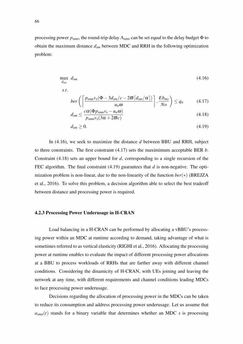
66
processing power psmn, the round-trip delay Λsmn can be set equal to the delay budget Φ to
obtain the maximum distance dsm between MDC and RRH in the following optimization
problem:
maxdsm
dsm (4.16)
s.t.
ber(⌈
psmnvs(Φ−3dsm/c−2ϖddsm/αe)unω
⌉,Ebms
No
)≤ qn (4.17)
dsm ≤cα(Φpsmnvs−unω)
psmnvs(3α +2ϖc)(4.18)
dsm ≥ 0. (4.19)
In (4.16), we seek to maximize the distance d between BBU and RRH, subject
to three constraints. The first constraint (4.17) sets the maximimum acceptable BER b.
Constraint (4.18) sets an upper bound for d, corresponding to a single recursion of the
FEC algorithm. The final constraint (4.19) guarantees that d is non-negative. The opti-
mization problem is non-linear, due to the non-linearity of the function ber(∗) (BREJZA
et al., 2016). To solve this problem, a decision algorithm able to select the best tradeoff
between distance and processing power is required.
4.2.3 Processing Power Underusage in H-CRAN
Load balancing in a H-CRAN can be performed by allocating a vBBU’s process-
ing power within an MDC at runtime according to demand, taking advantage of what is
sometimes referred to as vertical elasticity (RIGHI et al., 2016). Allocating the processing
power at runtime enables to evaluate the impact of different processing power allocations
at a BBU to process workloads of RRHs that are farther away with different channel
conditions. Considering the dinamicity of H-CRAN, with UEs joining and leaving the
network at any time, with different requirements and channel conditions leading MDCs
to face processing power underusage.
Decisions regarding the allocation of processing power in the MDCs can be taken
to reduce its consumption and address processing power underusage. Let us assume that
asmn(t) stands for a binary variable that determines whether an MDC s is processing
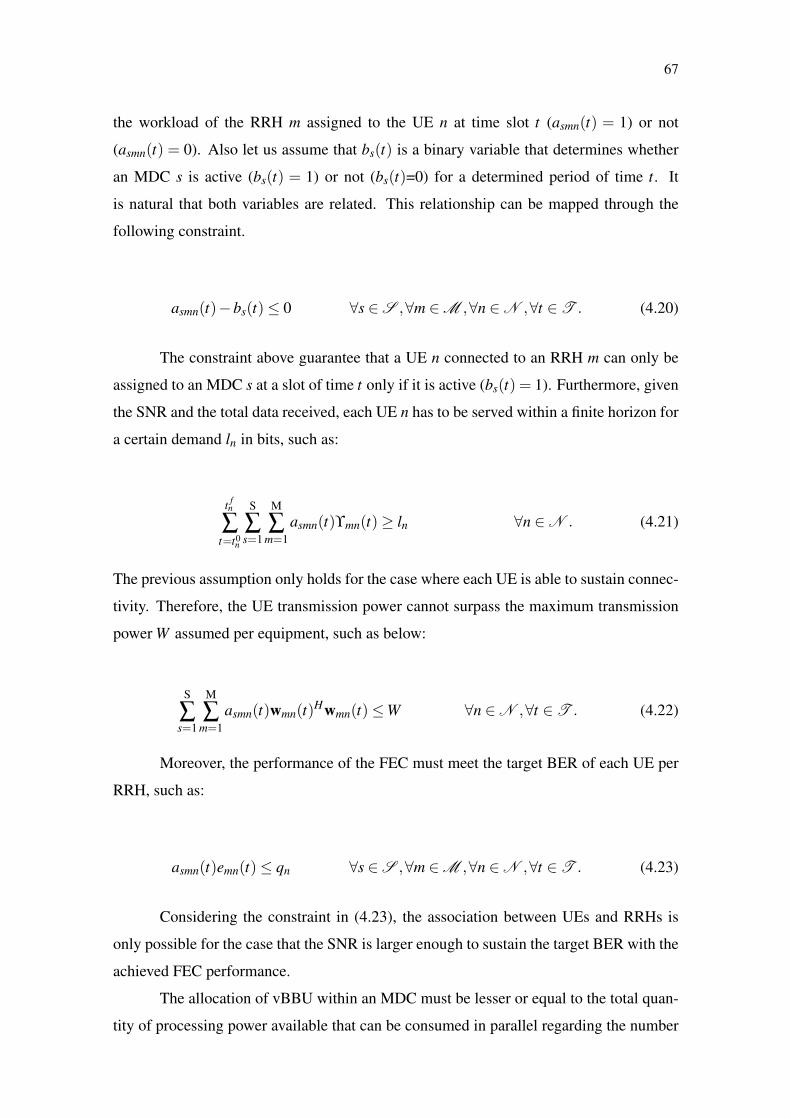
67
the workload of the RRH m assigned to the UE n at time slot t (asmn(t) = 1) or not
(asmn(t) = 0). Also let us assume that bs(t) is a binary variable that determines whether
an MDC s is active (bs(t) = 1) or not (bs(t)=0) for a determined period of time t. It
is natural that both variables are related. This relationship can be mapped through the
following constraint.
asmn(t)−bs(t)≤ 0 ∀s ∈S ,∀m ∈M ,∀n ∈N ,∀t ∈T . (4.20)
The constraint above guarantee that a UE n connected to an RRH m can only be
assigned to an MDC s at a slot of time t only if it is active (bs(t) = 1). Furthermore, given
the SNR and the total data received, each UE n has to be served within a finite horizon for
a certain demand ln in bits, such as:
t fn
∑t=t0
n
S
∑s=1
M
∑m=1
asmn(t)ϒmn(t)≥ ln ∀n ∈N . (4.21)
The previous assumption only holds for the case where each UE is able to sustain connec-
tivity. Therefore, the UE transmission power cannot surpass the maximum transmission
power W assumed per equipment, such as below:
S
∑s=1
M
∑m=1
asmn(t)wmn(t)Hwmn(t)≤W ∀n ∈N ,∀t ∈T . (4.22)
Moreover, the performance of the FEC must meet the target BER of each UE per
RRH, such as:
asmn(t)emn(t)≤ qn ∀s ∈S ,∀m ∈M ,∀n ∈N ,∀t ∈T . (4.23)
Considering the constraint in (4.23), the association between UEs and RRHs is
only possible for the case that the SNR is larger enough to sustain the target BER with the
achieved FEC performance.
The allocation of vBBU within an MDC must be lesser or equal to the total quan-
tity of processing power available that can be consumed in parallel regarding the number
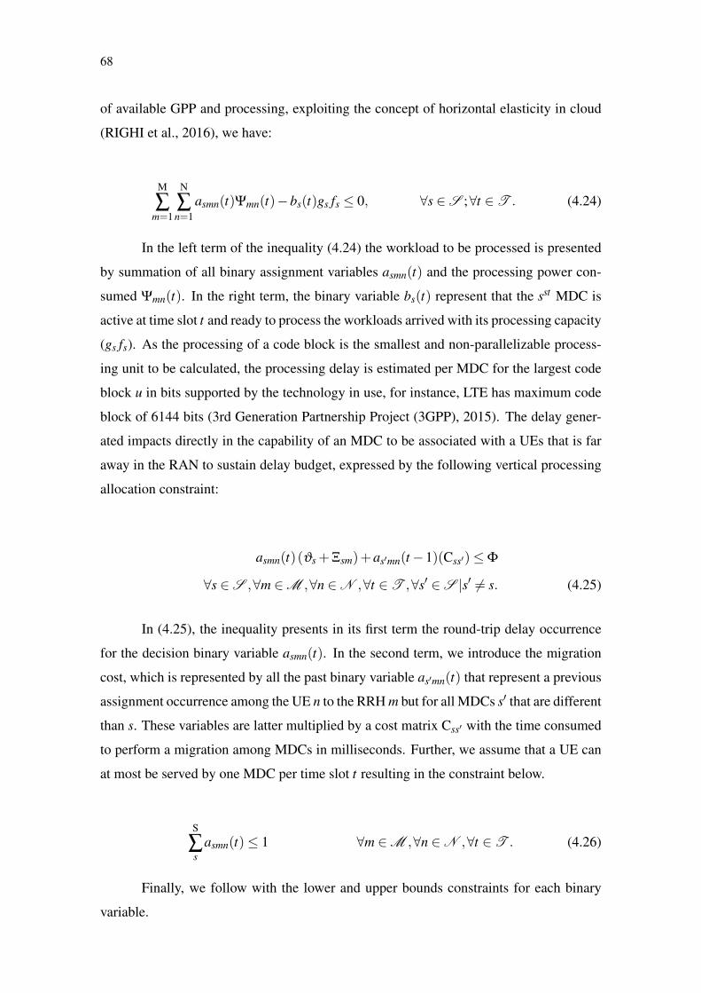
68
of available GPP and processing, exploiting the concept of horizontal elasticity in cloud
(RIGHI et al., 2016), we have:
M
∑m=1
N
∑n=1
asmn(t)Ψmn(t)−bs(t)gs fs ≤ 0, ∀s ∈S ;∀t ∈T . (4.24)
In the left term of the inequality (4.24) the workload to be processed is presented
by summation of all binary assignment variables asmn(t) and the processing power con-
sumed Ψmn(t). In the right term, the binary variable bs(t) represent that the sst MDC is
active at time slot t and ready to process the workloads arrived with its processing capacity
(gs fs). As the processing of a code block is the smallest and non-parallelizable process-
ing unit to be calculated, the processing delay is estimated per MDC for the largest code
block u in bits supported by the technology in use, for instance, LTE has maximum code
block of 6144 bits (3rd Generation Partnership Project (3GPP), 2015). The delay gener-
ated impacts directly in the capability of an MDC to be associated with a UEs that is far
away in the RAN to sustain delay budget, expressed by the following vertical processing
allocation constraint:
asmn(t)(ϑs +Ξsm)+as′mn(t−1)(Css′)≤Φ
∀s ∈S ,∀m ∈M ,∀n ∈N ,∀t ∈T ,∀s′ ∈S |s′ 6= s. (4.25)
In (4.25), the inequality presents in its first term the round-trip delay occurrence
for the decision binary variable asmn(t). In the second term, we introduce the migration
cost, which is represented by all the past binary variable as′mn(t) that represent a previous
assignment occurrence among the UE n to the RRH m but for all MDCs s′ that are different
than s. These variables are latter multiplied by a cost matrix Css′ with the time consumed
to perform a migration among MDCs in milliseconds. Further, we assume that a UE can
at most be served by one MDC per time slot t resulting in the constraint below.
S
∑s
asmn(t)≤ 1 ∀m ∈M ,∀n ∈N ,∀t ∈T . (4.26)
Finally, we follow with the lower and upper bounds constraints for each binary
variable.

69
0≤ asmn(t)≤ 1 asmn(t) ∈ Z,∀s ∈S ,∀m ∈M ,∀n ∈N ,∀t ∈T . (4.27)
0≤ bs(t)≤ 1 bs(t) ∈ Z,∀s ∈S ,∀t ∈T . (4.28)
Considering each of the aforementioned constraints enable to model the following
optimization problem:
min(al pha)T
∑t=1
S
∑s=1
M
∑m=1
N
∑n=1
asmn(t)Ψmn(t)gs fsvs
+(1−al pha)T
∑t=1
S
∑s=1
bs(t)ST
(4.29)
s.t.
(4.20)(4.21)(4.22)(4.23)(4.24)(4.25)(4.26)(4.27)(4.28)
In 4.29, a weighted multi-objective multi-variable binary linear minimization of
the overall processing power and consolidation can be achieved by assuming the best
allocation decisions for a finite horizon T presented by the binary matrix of variables
asmn(t) and the minimum number of active MDCs shown through the variables bs(t).
These decisions will be computed considering the weight al pha that will balance the
results. For a larger al pha, reducing the processing power consumption is prioritized.
Whereas, for a small alpha the reuse of MDCs is prioritized over reducing the processing
power consumption. The multi-objective function will present results as long as the re-
strictions (4.20) (4.21) (4.22) (4.23) (4.24) (4.25) (4.26) (4.27) (4.28) are met. A typical
solver based on Binary Integer Linear Programming (BILP), such as CPLEX or Mat-
lab, can be used to solve the problem due to its linearity. As the problem is BILP it is
NP-COMPLETE and presents (SMNT + ST) variables.
Since the the optimization in 4.29 requires complete knowledge of all the states
of a finite horizon, it becomes limited to solve off-line scenarios of H-CRAN. In this
case, this solution is not feasible to be used during runtime requiring an on-line decision
algorithm. Therefore, to execute on-line decision algorithms, a decision making system is
required to accommodate them being able to target the challenges identified in the context
of H-CRAN, such as proposed next.

70
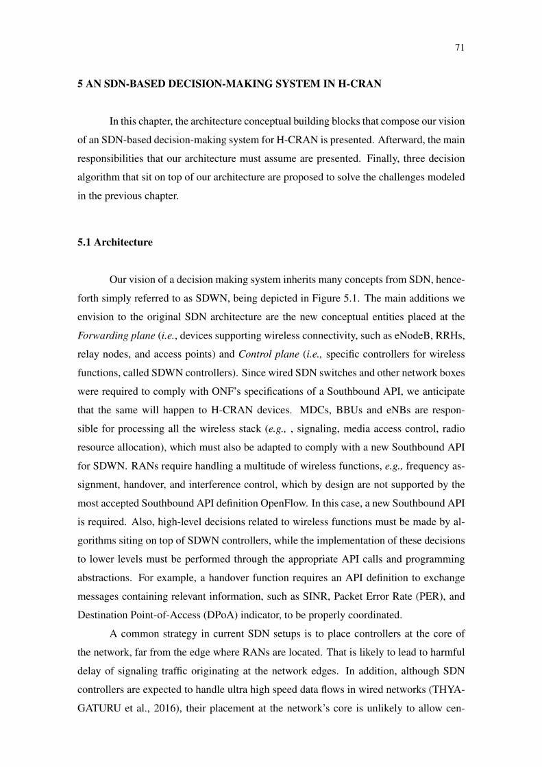
71
5 AN SDN-BASED DECISION-MAKING SYSTEM IN H-CRAN
In this chapter, the architecture conceptual building blocks that compose our vision
of an SDN-based decision-making system for H-CRAN is presented. Afterward, the main
responsibilities that our architecture must assume are presented. Finally, three decision
algorithm that sit on top of our architecture are proposed to solve the challenges modeled
in the previous chapter.
5.1 Architecture
Our vision of a decision making system inherits many concepts from SDN, hence-
forth simply referred to as SDWN, being depicted in Figure 5.1. The main additions we
envision to the original SDN architecture are the new conceptual entities placed at the
Forwarding plane (i.e., devices supporting wireless connectivity, such as eNodeB, RRHs,
relay nodes, and access points) and Control plane (i.e., specific controllers for wireless
functions, called SDWN controllers). Since wired SDN switches and other network boxes
were required to comply with ONF’s specifications of a Southbound API, we anticipate
that the same will happen to H-CRAN devices. MDCs, BBUs and eNBs are respon-
sible for processing all the wireless stack (e.g., , signaling, media access control, radio
resource allocation), which must also be adapted to comply with a new Southbound API
for SDWN. RANs require handling a multitude of wireless functions, e.g., frequency as-
signment, handover, and interference control, which by design are not supported by the
most accepted Southbound API definition OpenFlow. In this case, a new Southbound API
is required. Also, high-level decisions related to wireless functions must be made by al-
gorithms siting on top of SDWN controllers, while the implementation of these decisions
to lower levels must be performed through the appropriate API calls and programming
abstractions. For example, a handover function requires an API definition to exchange
messages containing relevant information, such as SINR, Packet Error Rate (PER), and
Destination Point-of-Access (DPoA) indicator, to be properly coordinated.
A common strategy in current SDN setups is to place controllers at the core of
the network, far from the edge where RANs are located. That is likely to lead to harmful
delay of signaling traffic originating at the network edges. In addition, although SDN
controllers are expected to handle ultra high speed data flows in wired networks (THYA-
GATURU et al., 2016), their placement at the network’s core is unlikely to allow cen-

72
Figure 5.1: Centralized decision making system architecture based on SDN concepts.
tralized SDWN controllers to scale with the extra control traffic coming from RANs. As
such, an important design consideration of SDWN is that the SDWN controller needs
to be positioned closer to the edge of the network. This entity adds scalability to the
Control plane by directly handling wireless specific functions. Although the SDWN con-
troller is a logically centralized entity, its implementation could be distributed across the
edge of H-CRAN, which brings about the discussion on the definition of horizontal inter-
controller APIs (e.g., Westbound and Eastbound) (JARSCHEL et al., 2014). Therefore,
SDWN controllers can still be distributed and also perform centralized logical functions,
such as global topology mapping, neighbor wireless resource information retrieving, link
discovery, and radio monitoring. Although these functions can be carried out in large time
scales, for others, such as radio resource management and spectrum sharing, the distance
of the radio device and the controller shortens due to delay constraints. We prefer to leave
the control plane homogeneous and leave the placement of the controllers as a topological
decision to be taken by the infrastructure owner or operators. It is also worth mention-
ing that some of the current SDWN proposals are distributed and present hierarchical
organization of controllers that provides partial control centralization (FIORANI et al.,
2015)(YANG et al., 2016). Such distribution enable controllers to decrease management
complexity keeping part of the centralization benefits (YANG et al., 2016). There is also
the possibility to pool resources, such as radio frequencies and processing power under
the control of SDWN controllers in H-CRAN (GUAN et al., 2014)(AMIN; MARTIN,
2016).
In cellular networks, centralized solutions turn feasible to achieve optimized de-
73
cisions because of the availability of the overall state of the network (AMIN; MARTIN,
2016); however, they are impracticable to be implemented on the current distributed ar-
chitecture of the RAN, regarding complexity and delay constraints (ZHANG et al., 2015).
In contrast, H-CRAN already envisions a topologically centralized architecture based on
resource pools to perform signal processing of the distributed RAN. Therefore, SDWN
can exploit this concept to tackle complexity and latency constraint by using these pools
and the existing optical backhaul (YANG et al., 2016). In this case, SDWN controllers can
take part as an enabling technology to perform centralized processing, becoming respon-
sible for different wireless functions coordination (WANG et al., 2016) (ABOLHASAN et
al., 2015). For example, SDWN controllers can be reprogrammed to analyze, allocate, and
redistribute radio resources, in addition to controlling the handover, interference, energy,
and radio resource sharing (AKHTAR; WANG; HANZO, 2016). Also, SDWN controllers
can serve as a framework to design novel solutions, for example, based on artificial in-
telligence to predict user handover mobility in a more harmonized manner, avoiding the
need of specialized protocols and network middle-boxes, such as IEEE 802.21 and LTE’s
Mobility Management Entity (MME). Although, H-CRAN can benefit from SDWN to
reach, for example, optimized solution for each different supported wireless function, the
definition of which wireless functions an SDWN controller must control and how, remains
undefined.
As in SDN, an SDWN controller can be tuned and reprogrammed by decision al-
gorithms at the Application plane through the Northbound API. The main difference from
a typical SDN setup is that SDWN allows algorithms to reconfigure wireless functions,
such as handover, inter-cell interference, and association control. The Northbound API
allows operators to dynamically redefine their entire RAN configuration, readjusting the
modus operandi of SDWN controllers.
Although SDWN enables endless possibilities, it is not a plug-and-play solution
to all problems and despite the different architectures proposed, there is still the lack of
a proper definition of what are the controller responsibilities to the realization of SDWN
in H-CRAN. As a consequence, the Southbound API is weakly defined without proper
specification and standardization. In this sense, we take a step further by defining the
responsibilities that an SDWN controller must assume in H-CRAN and propose a new
Southbound API definition. It is important mentioning that we are not extending Open-
flow, we are rather creating a different API specific for wireless functions. In the next
section, we introduce the responsibilities that an SDWN controller can assume to control
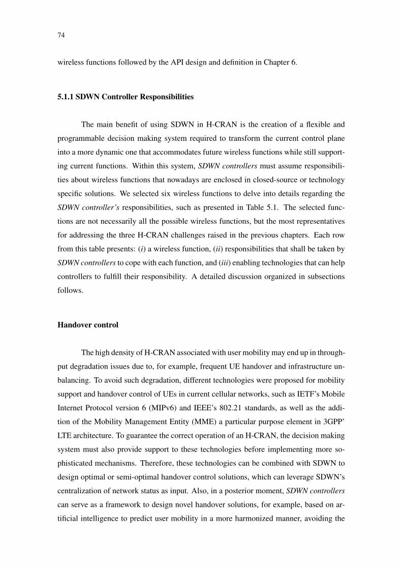
74
wireless functions followed by the API design and definition in Chapter 6.
5.1.1 SDWN Controller Responsibilities
The main benefit of using SDWN in H-CRAN is the creation of a flexible and
programmable decision making system required to transform the current control plane
into a more dynamic one that accommodates future wireless functions while still support-
ing current functions. Within this system, SDWN controllers must assume responsibili-
ties about wireless functions that nowadays are enclosed in closed-source or technology
specific solutions. We selected six wireless functions to delve into details regarding the
SDWN controller’s responsibilities, such as presented in Table 5.1. The selected func-
tions are not necessarily all the possible wireless functions, but the most representatives
for addressing the three H-CRAN challenges raised in the previous chapters. Each row
from this table presents: (i) a wireless function, (ii) responsibilities that shall be taken by
SDWN controllers to cope with each function, and (iii) enabling technologies that can help
controllers to fulfill their responsibility. A detailed discussion organized in subsections
follows.
Handover control
The high density of H-CRAN associated with user mobility may end up in through-
put degradation issues due to, for example, frequent UE handover and infrastructure un-
balancing. To avoid such degradation, different technologies were proposed for mobility
support and handover control of UEs in current cellular networks, such as IETF’s Mobile
Internet Protocol version 6 (MIPv6) and IEEE’s 802.21 standards, as well as the addi-
tion of the Mobility Management Entity (MME) a particular purpose element in 3GPP’
LTE architecture. To guarantee the correct operation of an H-CRAN, the decision making
system must also provide support to these technologies before implementing more so-
phisticated mechanisms. Therefore, these technologies can be combined with SDWN to
design optimal or semi-optimal handover control solutions, which can leverage SDWN’s
centralization of network status as input. Also, in a posterior moment, SDWN controllers
can serve as a framework to design novel handover solutions, for example, based on ar-
tificial intelligence to predict user mobility in a more harmonized manner, avoiding the

75
Table 5.1: SDWN controller responsibilitiesWireless function Controller responsibility Technology
Handover control
• Mobility accounting• Mobility prediction• Data flow orchestration• Transparency
• IEEE 802.21• Mobile IPv6 (MIPv6)
Interference control
• Intra-cell interference cognition• Inter-cell interference cognition• Interference avoidance orchestration• Control channel pollution minimization
• Enhanced Inter-Cell InterferenceCoordination (eICIC)
• Coordinated Multi-Point (CoMP)• Almost Blank Subframe (ABS)
Radio resource allocation• Calculate radio resource allocation• UEs associated per RRH and BS
• eICIC• CoMP• Software-Defined Radio (SDR)• Cooperative radio resource control• Cooperative self-organized networking
Sharing control
• Frequency bands division• Access granting• Accounting• Policy assurance
• Biding and Auction House• Licensed Shared Access (LSA)• Dynamic Spectrum Access (DSA)
Network orchestration
• Data-flow management• Data-flow redundancy• Cell association control• Admission Control
• Control And Provisioning of WirelessAccess Points (CAPWAP)
• OpenFlow• LTE-Self Organized Network
Energy control
• Configure maximum transmissionpower
• Switch On/Off devices• Co-channel maximum transmission
power
• Remote energy control mechanism• Wake up mechanism• Transmission power control
through SDR
need of specialized protocols, such as IEEE 802.21. As a proof of such statement and
contribution of this thesis, we investigate the use of SDWN for handover decisions in the
article of Tartarini et al. (TARTARINI et al., 2018). Also, we use the handover control to
associate UEs and RRHs throughout the three case studies presented in this thesis.
Interference control
As soon as macro and small cells start to intersect with each other in H-CRAN,
the improved data rate provided by these cell deployments degrades due to intra and
inter-cell interference (ZHANG et al., 2015). As a consequence, different technologies
have been exploited to alleviate interference at RANs, such as beamforming transmis-
sions using multi-user MIMO antennas, Almost Blank Subframes (ABS), and Enhanced
Inter-Cell Interference coordination (eICIC) mechanism. These technologies can have
their performance improved by the use of centralized solutions for inter/intra-cell inter-
ference coordination to reach near zero interference. As opposed to distributed solutions,
largely based on local signal strength indicators, centralized interference coordination has
76
the whole network state and frequency allocation, facilitating interference management.
In this sense, the processing centralization provided by H-CRAN combined to the SDWN
controller enables the coordination of the inter/intra-cell interference, allowing opera-
tors to design algorithms for interference coordination that best fit their network needs
(ZHANG et al., 2015)(WANG et al., 2016). Since SDWN controllers centralize interfer-
ence coordination, parameters, such as interference at receiver and frequency assigned
for each cell, can be used as input for optimized interference avoidance in H-CRAN. Al-
though the interference coordination can be improved, the number of signaling messages
increases, radio cells need to support sensing mechanisms, and event-based systems (e.g.,
traps) are required to send messages in case of interference detection. We investigate the
potential of SDWN as a decision making system for interference control and signaling
cost in the article of Marotta et al. (MAROTTA et al., 2017). Also, interference control is
performed in the first case study investigated in this thesis.
Processing and Radio resource allocation
Channels, resource blocks, and spectrum are typical examples of radio resources
that can be allocated in five domains, i.e., time, frequency, space, power, and coding.
For instance, frequency might be dynamically assigned to each small and macro cell
in H-CRAN to avoid interference and improve spectrum efficiency by exploiting spec-
trum reuse (AGYAPONG et al., 2014). Additionally, advanced radio virtualization tech-
niques allow the allocation and sharing of radio resources among multiple (Virtual) mo-
bile network operators (YANG et al., 2015), the exploitation of dynamic access tech-
niques (KANG; ZHANG; MOTANI, 2012), and even different access techniques, such
as Machine-to-Machine (M2M) (Kan Zheng et al., 2012), to allocate resources in a cel-
lular network. Technologies such as SDR provide the programmability required to adapt
the radio resource allocation in real time at the price of higher processing power require-
ments. This programmability also allows the utilization of advanced CoMP and eICIC
mechanisms to increase the spectral efficiency of radio communications as long as delay
constraints and processing power resources can be sustained.
SDWN can improve processing and radio resource allocation by centralizing the
knowledge of the wireless network exposing the programmability of networking devices
to high-level decision algorithms. However, the main constraints of using SDWN con-
trollers for processing power and radio resource allocation are related to delay constraints,

77
the increase of signaling messages, the integration of low-level radio baseband process-
ing with the conventional network protocol stack and hardware, and complexity to design
centralized resource algorithms that react to the local and fast paced changes of wireless
channel conditions (WANG et al., 2016). The processing and radio resource allocation
decisions in SDWN can change the processing power and the current channel bandwidth
improving their usage, such as investigated in the work of Marotta et al. (MAROTTA et
al., 2017). Also, the tradeoff between processing power allocation and channel conditions
under delay constraints is studied in the work of Marotta et al. (MAROTTA et al., 2018a).
Sharing control
High leasing prices and spectrum scarcity lead operators to exploit spectrum shar-
ing to improve their resource pool and budgeting (DOYLE et al., 2014). To take advan-
tage of spectrum sharing, different techniques can be used, e.g., Dynamic Spectrum Ac-
cess (DSA) and Licensed Shared Access (LSA) in combination with cognitive radio and
auction systems. With SDWN, operators can control the access technique used to explore
shared frequencies. In this sense, SDWN controllers become responsible for providing
information sharing among operators, enabling better control of shared frequencies, and
assuring that operators’ policies are correctly applied. Nevertheless, depending on spec-
trum access technique taken, the SDWN controller role changes. For example, in LSA the
SDWN controller becomes limited to coordinate spectrum sharing only if a spectrum bro-
ker is present in the coordinated area. The usage of spectrum and infrastructure sharing
within a centralized decision-making system is studied in Marotta et al. (MAROTTA et
al., 2015) and Marotta et al. (MAROTTA et al., 2018b). Next, in the first case study, we
exploit the sharing control responsibility of wireless controllers to reduce interference in
an H-CRAN.
Network orchestration
H-CRAN infrastructure includes many heterogeneous elements, such as BSs, BBUs,
RRHs, and APs, operating under a variety of protocols to forward data and to interact
with one another. Achieving, for example, optimal traffic routing in this context is infea-
sible without some sort of lingua franca among technologies. SDWN can improve this
78
scenario with network orchestration, by centralizing information from different sources
and communicating with elements of interest all over the network. While requiring trap
systems for event detection and possibly increasing signaling traffic, SDWN controllers
become a bridge for integrating well-known protocols, such as OpenFlow and CAPWAP,
to coordinate other elements (including other SDN Controllers) performing cross tech-
nology operations. The usage of decision algorithms with SDWN considering network
orchestration is investigated in the work of Tartarini et al. (TARTARINI et al., 2018).
Energy control
Energy consumption in a cellular network can be divided into two perspectives
from (i) operators and (ii) UEs. In the former, operators are concerned with infrastruc-
ture equipment energy consumption, for example, RRHs and BBUs. In the latter, UEs
must preserve their energy to maximize battery life by minimizing transmission power
and retransmissions. There is a tradeoff between both perspectives, where infrastructure
equipment consumes more energy to reduce UEs consumptions (China Mobile Research
Institute, 2011). SDWN can be used to turn the energy control programmable. SDWN
controllers must control the energy tradeoff by configuring the maximum allowed co-
channel interference and transmission power, allowing operators to balance the tradeoff
as they see fit. Also, the SDWN controller shall be able to switch off/on wireless equip-
ment that is not in use, for example, an RRH without UEs in its vicinity. Thus saving
energy, but increasing node unavailability in case a cell is erroneously turned off while
in use. Access to such a command must be protected against unauthorized use. Decision
algorithms revolving energy control in H-CRAN are studied in the work of Marotta et al.
(MAROTTA et al., 2017) and D’Oro et al. (D´ORO et al., 2018).
– – –
It is important to notice that the aforementioned wireless functions are not novel by them-
selves. In fact, there are purpose specific controllers already in place for some of them,
e.g., the MME controls intra-LTE handover events. However, these controllers were not
designed for dynamic reprogramming, hindering the deployment of network applications
and the fast evolution of cellular networks and H-CRAN. Moreover, SDWN can be used
in H-CRAN to achieve outstanding benefits, which include optimal interference avoid-
ance and frequency assignment, as well as improved energy control and spectrum shar-
79
ing. On top of the proposed architecture, different H-CRAN challenges can be addressed
according to decision algorithms. In this case, next, we propose three decision algorithm
to sit on top of the proposed architecture being able to address the challenges of H-CRAN
described in the previous Chapter.
5.2 Decision algorithms
In this section, two decision algorithms are proposed to run on top of the proposed
SDWN architecture. In the first, interference and resource sharing decisions are made
considering an algorithm that can update, distribute, and control the power of shared
RRHs in H-CRAN. In the second, delay constraints dictates the tradeoff of processing
power allocation and maximum distance between MDC and RRH in H-CRAN observed
in two decision algorithm with slightly different objectives, changing according to the
inputs provided.
5.2.1 Minimal Interference with Maximum Throughput though a Resource Sharing
Decision Algorithm
Considering the problem modeled in (4.12), the solution can only be found for a
determined horizon T. In practice, T is not known during runtime of an H-CRAN. In this
case, we designed a decision algorithm executed per slot of time t that sits on top on an
SDWN controller that (i) reconfigures the channel bandwidth to best fit the UE demands
according to the LTE configurations, i.e., [1.4, 3, 4, 5, 10, 15, 20] MHz, (ii) reduce the
overall interference by assigning the channel with the lowest SINR, i.e., the channel least
used in the RRH neighborhood, and (iii) switch the operation mode of RRHs based based
on the number of UE’s in the RRH vicinity, i.e., idle if no UEs are in the RRH vicinity
and active otherwise.
Algorithm 1 presents a pseudo code that contains the main operations performed
by the application plane. The power control and channel bandwidth reconfiguration are
executed only when the SDWN controller receives the BW update message (line 1), which
is better explained in the following chapter. As the first step, the power control routine
is triggered for a given RRH (line 16). In this routine, the SDWN controller estimates
the potential set of UEs to associate or migrate to an RRH m due to their positioning and

80
interference (line 17). Afterward, the application determines if an RRH being analyzed
(m) will accept a UE that is migrating from other RRH (m′) determining: (a) if m is current
number of UEs connected is larger than the population of connected UEs from m′; (b) if
m′ is saturated or cannot afford the capacity required by the UE (line 19); and (c) if n is
a donor subscriber and m′ has more UEs from leasers than the policy established χMmaxm
(line 22), they are dropped to serve the donor subscribers to meet the objective function
from (4.12). Otherwise, the RRH rejects the UE access (line 26). This way RRHs are
shared until achieving saturation before activating a new RRH, such as constraint (4.13)
dictates.
Further, the algorithm uses the controller available information to estimate the nec-
essary channel bandwidth considering the UEs modulation and coding scheme, SINR, and
PER for each connected UE (line 3). Afterward, the RRH is configured with the channel
bandwidth that satisfies all UEs and that corresponds to a valid LTE configuration (line 4)
and updates the channel distribution (line 5). Starting the update, the SDWN controller
estimates the channel with best SINR (line 8) and assigns it to RRH (line 9). Because
the decision of changing the channel of one RRH modifies the interference conditions of
all adjacent antennas calculated by using the formula from (4.11), the ChannelDistribu-
tionUpdate is performed per RRH (lines 10− 12). Moreover, as clusters of small cells
will hardly interfere with each other due to small coverage area of RRHs, it is not likely
that the ChannelDistributionUpdate will be executed for all RRHs in the H-CRAN. The
algorithm complexity is O(M4 +M2 ∗N).
5.2.2 Maximizing Distance Between MDC and RRH Algorithms
The optimization problem (4.16) is non-linear and the function ber(∗) does not
present a closed form, requiring the problem to be discretized (BREJZA et al., 2016). We
exploit the nearest integer solution presented in (HASTAD et al., 1989). Considering d
as a discrete integer variable, with d ≥ 0, and noticing that the maximum value of d can
be achieved when processing delay becomes zero, we can determine a finite integer range
that contains all possible d. We designed a heuristic exhaustive search decision algorithm
that scales d within the finite range, with a precision of meters, until all proposed con-
straints are met for a given processing power pn and target BER b to achieve the nearest
integer optimal solution.
In algorithm 2, the round-trip delay budget Φ, the threshold α , the set of distances

81
Algorithm 1 Bandwidth update, channel distribution, and power control applicationsEnsure: RRHn is the RRH that a UE n is currently connectedEnsure: UELm is the list of UEs connected to RRH mEnsure: UELdonor is the list of subscribed UEsEnsure: UELdonor
m is the list of subscribed UEs connected to RRH mEnsure: UELleaser
m is the list of leasing UEs connected to RRH mEnsure: INTm is the list of RRHs interfering with RRH m
1: procedure RECEIVEDBWUPDATEMESSAGE(RRH m)2: trigger PowerControl(RRH m)3: reqBW ← Sum( BW required by UEs in UELm)4: Configure RRH m channel to satisfy reqBW5: trigger ChannelDistributionUpdate(RRH m)6: end procedure7: procedure CHANNELDISTRIBUTIONUPDATE(RRH m)8: Estimate the channel with greater SINR for RRH m9: Configure RRH m to use channel with best SINR
10: if RRH m channel changed then11: for all RRH i in INTr do12: trigger ChannelDistributionUpdate(i)13: end for14: end if15: end procedure16: procedure POWERCONTROL(RRH m)17: Estimate the set of UEs interested in migrate to m18: for all UE n in UEs do19: if sizeof (UELm) smaller than sizeof(UELRRHn) and m′ is unable to sustain n
then20: UE n has access granted to RRH m21: else22: if n ∈ UELdonor and sizeof (UELleaser
m ) larger than χMmaxm and m′ is un-
able to sustain n then23: Disconnect a UE from (UELleaser
m ) and add it to the list of UE to beserved
24: UE n has access granted to RRH m25: else26: UE n has the access denied to RRH m27: end if28: end if29: end for30: end procedure
D, the maximum number of recursions K, a target BER q, and the processing power
allocated psmn is known for a given MDC s, RRH m, and UE n from information gathered
at the SDWN controller. For each code block evaluated we used a function minK(EbmNo ,
q) to minimize the number of recursions k iterating until achieve the maximum K or a
minimum target BER q through the function ber(k, EbmNo ).

82
Algorithm 2 Maximum distance for a given processing power1: Φ, psmn, S, d, K, and q are known2: k← minK(Ebm
No , q)3: for d ← D do4: h← dd
Se5: p← kLmF
O(Φ−[3d/c+2Ah])6: if p ≤ psmn then7: Maxd = d8: else9: return Maxd
10: end if11: end for12: procedure MINK(Ebm
No , q)13: for k← [1..K] do14: if ber(k, Ebm
No ) ≤ q then return k15: end if16: end for17: end procedure
Given k, we loop the distances d in D determining the number of hops h per iter-
ation. Afterward, for each new d and h we solve the equality (4.8) for a given round-trip
delay budget Φ and isolating p. Afterwards, p is compared to the allocated processing
power psmn to decide what is the maximum distance supported to sustain H-CRAN oper-
ant. The algorithm presented has complexity of O(K+D) for a given psmn.
5.3 Minimizing Processing Power Underusage Algorithm
To solve the processing power underusage problem in H-CRAN, the optimization
proposed in 4.29 requires knowing every slot of time of a finite horizon to be calculated.
In this sense the optimization is running on top of an offline version of H-CRAN, where
every state and possibility is known by the system. This optimization cannot be used
for real deployments of H-CRAN, where information can only be obtained for past slots
of time and the future is unknown. Moreover, MBILP optimizations are combinatorial
search algorithms that scales very fast for small growing in the scenario. Therefore, we
propose an online greedy algorithm in 3 capable of exploit the tradeoff of reducing pro-
cessing power consumption and increase consolidation through MDC reuse achieving
near optimal solution for the processing power underusage problem in H-CRAN.
In algorithm 3, the weight al pha, the current time slot slot, the delay budget Φ, the
sets of UEs N , RRHs M , MDCs S , total time considered T, the aggregated function

83
value from the previous time slot f val(t − 1), the binary variables a and b filled until
time slot t and the UEs total transmitted data achieved in previous time slots ([1..t− 1])
total_transmitted are known. We start by creating two auxiliary parameters, maxproc
which is the total processing available in the while H-CRAN; and t_processing which is
a vector containing the availabe processing per MDC s. Afterwards, we create a procedure
to calculate the users transmission priority for the current time slot. In this case, in line
26, we create the procedure PRIORITY() to bias each UE considering the connected RRH
and associated MDC. In line 27, we instantiate a matrix of priorities with zeros for all
possible UEs, RRHs, and MDCs assignment. Afterwards, we iterate over all possible
assignments such that the matrix pp is populated with the results from the equation in
line 32.The equation in line 32 is the same equation from 4.29 except from the first term
that add the concept of the transmission deadline. Since the greedy algorithm does not
hold information from all future slots, we must guarantee that UEs with closer deadlines
have priority over those with larger time window to transmit. It is important to keep in
mind that even with this modification the system may not guarantee that all UEs will be
able to successfully attend to the initial request, which is part of the why this solution
is suboptimal. The equation is calculated for every possible assignment of UEs, RRHs,
and MDCs populating the matrix pp. Finally, at the end of the procedure, pp is sorted in
descending creating the matrix of priorities.
The matrix of priorities has its indexes extracted in terms of s, n, and m, which
are looped sequentially in line 7 of the Algorithm 3. Afterwards, each of the conditions
inherited from the problem 4.29 are checked. In line 8, we check whether the UEs n still
needs to transmit or not by comparing the total_transmitted vector against the initial de-
mand ln. Further, in line 9, we check if the current slot of time t is within the transmission
window of the UE. Next, in line 10, we check if the target BER qn is met. In line 11,
we check the horizontal allocation constraint to guarantee that an MDC s has processing
power enough to accommodate the workload Ψmn(t) being assigned. Whereas, in line 12,
the vertical allocation constraint is verified for the case that the round-trip delay Λsmn(t)
is lesser or equal then the delay budget Φ. Finally, in line 13, we guarantee that the UE
being checked was not already served by iteratively testing all the previous assignments
generated during the loop which is necessary for the greedy algorithm to converge.
Since all the constraints were met until line 14 of Algorithm 3, we can proceed
with the assignment. The assignment in the algorithm will instantiate all necessary binary

84
Algorithm 3 Greedy processing power underusage minimization1: al pha, t, Φ, N , M , S , T, f val, a, b and total_transmitted are known2: maxproc← 03: for s′← [1..S] do maxproc← maxproc + vs′+ fs′+gs′
4: end for5: for s′← [1..S] do t_processings′ ← vs′+ fs′+gs′
6: end for7: for s, m, n← PRIORITY(al pha, t, N , M , S , T, maxproc) do8: if total_transmitted(n) ≥ ln then9: if t ≥ t0
n and t ≤ t fn then
10: if ber(X , Γsmnt) ≤ qn then11: if Ψmn(t) ≤ t_processing(s)s then12: if Λsmn(t) ≤ Φ then13: if not already_served(S, n, t) then14: asmn(t)← 115: bs(t)← 116: t_processing(s) = t_processing(s)−Ψmn(t)17: total_transmitted(n) = total_transmitted(n)+ϒmn(t)18: f val = f val +al pha Ψmn(t)
maxproc − (1−al pha) 1S∗T
19: end if20: end if21: end if22: end if23: end if24: end if25: end for26: procedure PRIORITY(al pha, t, N , M , S , T, b)27: ppsmn← 0; ∀s ∈S ,∀m ∈M ,∀n ∈N28: for n← [1..N] do29: if t ≤ t f
n and t ≥ t0n then
30: for s← [1..S] do31: for m← [1..M] do32: if t > 1 then33: ppsmn← 1
t fn +1−t)
−al pha Ψmn(t)maxproc − (1−al pha)bs(t−1)
S∗T34: else35: ppsmn← 1
t fn +1−t)
−al pha Ψmn(t)maxproc
36: end if37: end for38: end for39: end if40: end for41: pp← SORT(pp, ’descending’)42: return INDEXOF(pp)43: end procedure
85
variable of asmn(t) and bs(t) to the value of 1 in lines 14 and 15. Also, it will decrease
the total processing power available t_processings for the sth MDC assigned. The total
transmitted total_transmittedn of the nth UE is increased. Finally, the function value of
the system f val is summed considering the same equation from problem 4.29 to be latter
compared. This algorithm presents a complexity of 2*(S*M*N) which is executed once
per time slot.
In the next chapter, we prototype the proposed SDN-based decision-making sys-
tem that will host the algorithms designed.

86

87
6 PROTOTYPE AND INTERFACE DEFINITION
We developed a prototype of a centralized decision making system, where a con-
troller exchange messages with H-CRAN networked nodes, e.g., MDCs and RRHs. First,
we determine the southbound interface required to implement our proposed system based
on SDWN controllers considering RESTful concepts. Afterward, we delve in detail re-
garding the prototype of our controller.
6.1 Controller Interface
For each wireless function, our southbound interface presents a set of RESTful
resources that can be changed according to the methods: Create; Read; Update; and
Delete (CRUD) (FIELDING; TAYLOR, 2002). These resources were designed to enable
control and forwarding plane entities to interact, such as summarized in Table 6.1.
To perform radio resource allocation, the southbound resource channel can be
instantiated by a controller using the create method determining which PoA (node) of
a BBU will receive a determined frequency (c_ f requency) with a certain bandwidth
(c_bandwidht). Also, the resource can start to be used at a certain period (start_time)
and send a notification to check whether the current configuration is still valid after a cer-
tain period (timetokeep). The same resource can be used to get the current status of the
channel in use of a node, receiving a list of radio parameters (radio_parameters), e.g.,
average RSSI and the number of UE currently connected consuming the channel. Other
methods, such as update and delete, can be used to change the current configuration or
destroy it. Considering the same logics, we detail each of the other resources, briefly.
The dmimo resource can be used to enable, check, change, or stop the execu-
tion of MIMO between RRHs (nodea and nodeb). To perform handover control, the
handover resource can be used to start, get status, change or stop a UE (ue) migration
from an origin (poa) to a destination PoA (d poa) considering different radio parameters
(radioparameters). Whereas, the handoff resource cannot be instantiated by the con-
troller directly, but can be used by a BBU or eNB to notify the controller about a UE (ue)
departure from one of its RRHs (poa) containing radio parameters (radio_parameters)
when necessary.
The rssi_event, in turn, is a resource instantiated by BBUs and eNBs to inform
that an RRH (node) is facing bad channel (c_ f requency and c_bandwidth) quality (ra-

88
Table 6.1: SDWN southbound interfaceWireless function Resource
Radio resource allocation
• channel(node, start_time, time_to_keep,c_ f requency, c_bandwidth,radio_parameters)
• dmimo(nodea, nodeb, ue_id,c_ f requency,c_bandwidth, c_rssi)
Handover control • handover(ue, poa, d poa, radio_parameters)• handoff(ue, poa, radio_parameters)
Interference control
• rssi_event(node, c_ f requency,c_bandwidth, radio_parameters)
• interference_check(node, c_ f requency,c_bandwidth)
Sharing control
• dsa(node_set, c_ f requency,c_bandwidth, radio_parameters)
• lsa(node_set, c_ f requency,c_bandwidth, start_time, time_to_keep)
Networking orchestration• openflow(*)• connection(ue, poa, radio_parameters)• disconnection(d poa)
Power control
• wakeup(poa)• standby(poa, start_time, time_to_keep)• maximum_power(poa, power,
radio_parameters)
dio_parameters) that must be investigated. The inter f erence_check resource enables
BBUs and eNBs to request the SDWN controller to check whether there are other RRHs
from different RANs using the same channel frequencies (c_ f requency and c_bandwidth).
To perform sharing control, the dsa and lsa resources can be used to determine the current
frequency sharing regime in use, in this case, DSA or LSA, respectively. In both cases,
a set of RRHs (nodeset) must be determined considering different inputs, i.e., frequen-
cies in use (c_ f requency and c_bandwidth), radio parameters (radio_parameters), start
period (start_time) and time to request update (time_to_keep).
In terms of network control, the openflow interfaces (open f low(∗)) must be con-
sidered to perform data flow management and control. Whereas, the association and
disconnection control of UEs can be performed through the use of connection and dis-
connection resources, using messages containing e.g., the UE id ue and radio parameters,
such as PER and Received Signal Strength Indication (RSSI). Finally, power control can
be performed by the usage of wakeup, standby, and maximum_power resources, which
enable to activate or deactivate an RRH, put it in standby mode (the RRH is on but do
not perform transmissions or receptions), and set the maximum transmission power of an
RRH. Considering the proposed interfaces, we developed our SDWN prototype.
89
6.2 H-CRAN and decision making system prototype
The proposed interface must be deployed within a decision making system to be
evaluated in H-CRAN. In this case, first, we describe the prototype of nine setups of
H-CRAN to serve as simulation scenarios to perform our evaluation. Afterward, the sys-
tem prototype is presented and briefly described.
6.2.1 H-CRAN prototype
Our decision making system was developed to operate on top of H-CRAN scenar-
ios. Our scenarios consist on different configurations of an H-CRAN with low, medium
and high density of UEs ([100, 500, 1000] UEs/Km2 respectively). Each UE density
is combined with a scarce, medium or dense number of RRHs ([5, 15, 30] RRHs/Km2,
respectively). This results in nine different scenarios, varying from low-density-UEs-low-
density-RRHs to high-density-UEs-high-density-RRHs (MAROTTA et al., 2015). Each
of the nine scenarios were simulated in a custom-made simulation tool designed specifi-
cally for H-CRAN scenarios that have its source code published in GitHub1.
We modeled H-CRAN based on (3rd Generation Partnership Project (3GPP), 2010,
Annex A), considering the communication between UEs and RRHs through free space
path loss, with a thermal noise of −90 dBm, Orthogonal Frequency-Division Multiple
Access (OFDMA), and modulation code scheme. RRHs were configured with a maxi-
mum transmission power of 23 dBm, antenna gain of 0 dBi, and connected to the closest
BBU pool. The energy being consumed by the RRH varies according to its operation
mode, 4.3 W when idle (sleeping) and 6.8 W when active (AUER et al., 2011).
A macrocell is placed in the center of the grid and configured with maximum
transmission power of 46 dBm and antenna gain of 0 dBi. UEs move along the grid
according to a random waypoint mobility model with a pause interval of 10s and with
a speed ranging from 1 to 40 m/s (BAI; HELMY, 2004). Each UE is modeled with a
Constant Bitrate (CBR) traffic demand of 5 Mbps. Thus, the total traffic demand increases
with the number of UEs as follows: 0.5 Gbps/km2 for 100 UEs, 2.5 Gbps/km2 for 500
UEs, and 5 Gbps/km2 for 1000 UEs.
In each scenario, we deployed our decision making system as an SDWN controller
responsible for managing radio resource allocation and the operation mode of all RRHs,1Source code: https://github.com/ComputerNetworks-UFRGS/hcran-simulator
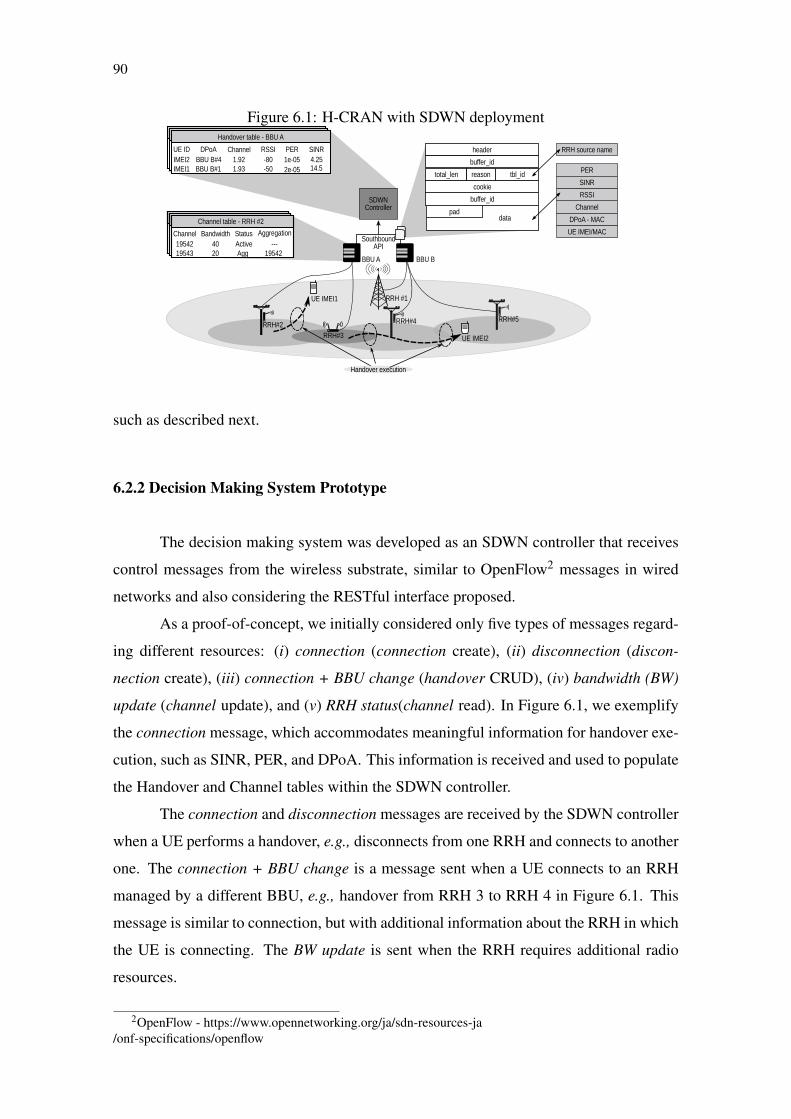
90
Figure 6.1: H-CRAN with SDWN deployment
such as described next.
6.2.2 Decision Making System Prototype
The decision making system was developed as an SDWN controller that receives
control messages from the wireless substrate, similar to OpenFlow2 messages in wired
networks and also considering the RESTful interface proposed.
As a proof-of-concept, we initially considered only five types of messages regard-
ing different resources: (i) connection (connection create), (ii) disconnection (discon-
nection create), (iii) connection + BBU change (handover CRUD), (iv) bandwidth (BW)
update (channel update), and (v) RRH status(channel read). In Figure 6.1, we exemplify
the connection message, which accommodates meaningful information for handover exe-
cution, such as SINR, PER, and DPoA. This information is received and used to populate
the Handover and Channel tables within the SDWN controller.
The connection and disconnection messages are received by the SDWN controller
when a UE performs a handover, e.g., disconnects from one RRH and connects to another
one. The connection + BBU change is a message sent when a UE connects to an RRH
managed by a different BBU, e.g., handover from RRH 3 to RRH 4 in Figure 6.1. This
message is similar to connection, but with additional information about the RRH in which
the UE is connecting. The BW update is sent when the RRH requires additional radio
resources.
2OpenFlow - https://www.opennetworking.org/ja/sdn-resources-ja/onf-specifications/openflow
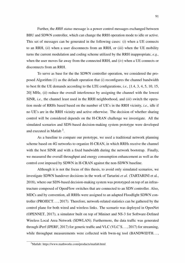
91
Further, the RRH status message is a power control messages exchanged between
BBU and SDWN controller, which can change the RRH operation mode to idle or active.
This set of messages can be generated in the following cases: (i) when a UE connects
to an RRH, (ii) when a user disconnects from an RRH, or (iii) when the UE mobility
turns the current modulation and coding scheme utilized by the RRH inappropriate, e.g.,
when the user moves far away from the connected RRH, and (iv) when a UE connects or
disconnects from an RRH.
To serve as base for the the SDWN controller operation, we considered the pro-
posed Algorithm (1) as the default operation that (i) reconfigures the channel bandwidth
to best fit the UE demands according to the LTE configurations, i.e., [1.4, 3, 4, 5, 10, 15,
20] MHz, (ii) reduce the overall interference by assigning the channel with the lowest
SINR, i.e., the channel least used in the RRH neighborhood, and (iii) switch the opera-
tion mode of RRHs based based on the number of UE’s in the RRH vicinity, i.e., idle if
no UE’s are in the RRH vicinity and active otherwise. The decision of whether sharing
control will be considered depends on the H-CRAN challenge we investigate. All the
simulated scenarios and SDN-based decision-making system prototype were developed
and executed in Matlab 3.
As a baseline to compare our prototype, we used a traditional network planning
scheme based on 4G networks to organize H-CRAN, in which RRHs receive the channel
with the best SINR and with a fixed bandwidth during the network bootstrap. Finally,
we measured the overall throughput and energy consumption enhancement as well as the
control cost imposed by SDWN in H-CRAN against the non-SDWN baseline.
Although it is not the focus of this thesis, to avoid only simulated scenarios, we
investigate SDWN handover decisions in the work of Tartarini et al. (TARTARINI et al.,
2018), where our SDN-based decision-making system was prototyped on top of an infras-
tructure composed of OpenFlow switches that are connected to an SDN controller. Also,
MDCs and by convention, all RRHs were assigned to an adapted Floodlight SDWN con-
troller (PROJECT. . . , 2017). Therefore, network-related statistics can be gathered by the
control plane for both wired and wireless links. The scenario was deployed in OpenNet
(OPENNET, 2017), a simulator built on top of Mininet and NS-3 for Software-Defined
Wireless Local Area Network (SDWLAN). Furthermore, the data traffic was generated
through iPerf (IPERF, 2017) for generic traffic and VLC (VLC’S. . . , 2017) for streaming,
while throughput measurements were collected with bwm-ng tool (BANDWIDTH. . . ,
3Matlab: https://www.mathworks.com/products/matlab.html

92
2017).
In the next section, we present case studies to quantify some of the benefits of
SDN-based decision-making system, when interference, sharing, processing allocation
are coordinated by SDWN controllers in an H-CRAN scenario.
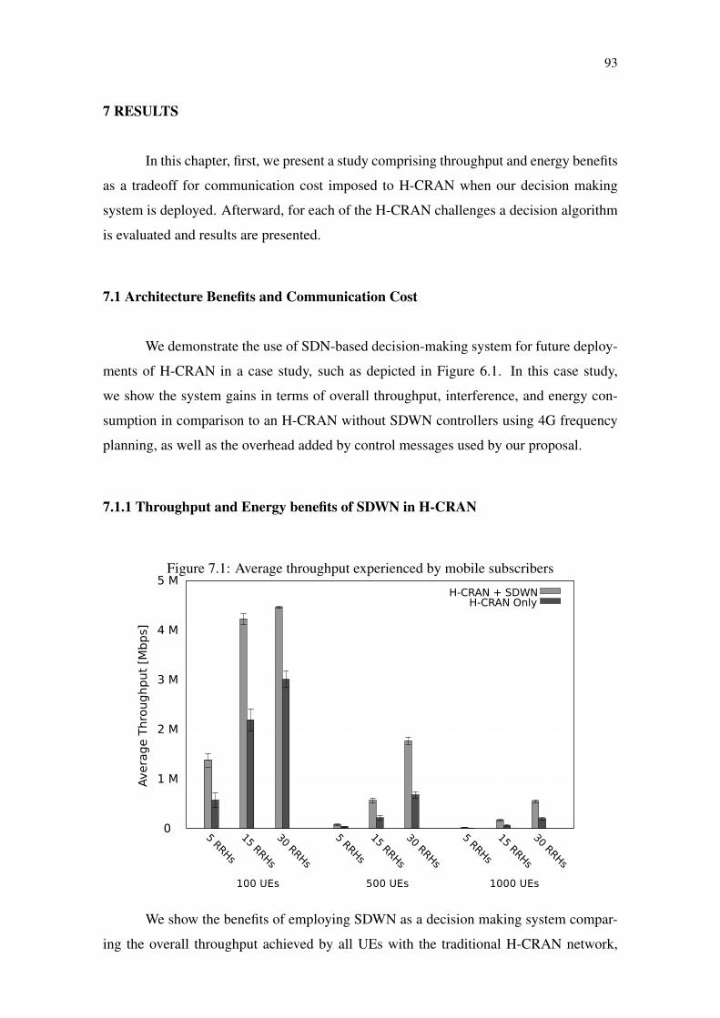
93
7 RESULTS
In this chapter, first, we present a study comprising throughput and energy benefits
as a tradeoff for communication cost imposed to H-CRAN when our decision making
system is deployed. Afterward, for each of the H-CRAN challenges a decision algorithm
is evaluated and results are presented.
7.1 Architecture Benefits and Communication Cost
We demonstrate the use of SDN-based decision-making system for future deploy-
ments of H-CRAN in a case study, such as depicted in Figure 6.1. In this case study,
we show the system gains in terms of overall throughput, interference, and energy con-
sumption in comparison to an H-CRAN without SDWN controllers using 4G frequency
planning, as well as the overhead added by control messages used by our proposal.
7.1.1 Throughput and Energy benefits of SDWN in H-CRAN
Figure 7.1: Average throughput experienced by mobile subscribers
H-CRAN + SDWNH-CRAN Only
We show the benefits of employing SDWN as a decision making system compar-
ing the overall throughput achieved by all UEs with the traditional H-CRAN network,
94
which uses a fixed channel bandwidth. Moreover, we compared our system’s power con-
trol gains considering Algorithm 1 execution against a baseline where RRHs are always
active.
Figure 7.1 shows the average throughput of UEs for each of the nine evaluated
scenarios presented in Subsection 6.2.1. In all scenarios, employing SDWN to monitor
UEs handover and perform frequency assignment increased the average throughput by
approximately 40% when compared with the 3G/4G baseline. This gain occurs because
SDWN reduces the inter-tier interference by managing the channel distribution during
runtime, which in turn increases the average SINR and enables better modulation and
coding schemes. However, for a fixed number of RRHs, increasing the number of UEs de-
creases the average throughput. This occurs because the limited available radio resources
are divided among a larger number of UEs. For the same reason, the average throughput
increases with the number of RRHs, i.e., the average number of UEs connected to an RRH
is lower, facilitating the reuse of radio resources.
Figure 7.2: Percentage of communications performed relative to the number of interferers
H-CRAN + SDWNH-CRAN Only
To better understand the benefits of the channel bandwidth and distribution ap-
plication, we show the percentage of UEs transmission as a function of the number of
RRHs interfering with their communication in Figure 7.2(b). Approximately 70% of the
transmissions were performed without interference, i.e., the channel had an interference
in terms of energy lesser than -90 dB, with the H-CRAN standard channel distribution
algorithm, whereas with the use of SDWN this number goes up to roughly 96%.

95
The power control application achieved energy gains maintaining RRHs in idle as
long as others are not saturated, as can be seen in Figure 7.3. For scenarios with small
densities, such as 100 UEs/km2, this application achieved 20% of energy reduction for
high number of RRHs, a significant mark for large networks. Whereas, for scenarios with
high densities, such as 1000 UEs/km2, the SDWN gains decrease achieving 6% at best for
30 RRHs. It is important to notice the tradeoff between increasing the number of RRHs
and the energy gains achieved. In this case, the results in this work can serve as guidelines
for operators to identify which is the best number of RRHs to be deployed in an H-CRAN
comparing energy gains and the total capacity achieved.
Figure 7.3: Average energy consumption per RRHH-CRAN + SDWN
H-CRAN Only
7.1.2 Control message cost of SDWN in H-CRAN
The main drawback of employing an SDWN Controller is the additional overhead
incurred by control messages. Figure 7.4 shows the number of control messages of each
type for all evaluated scenarios. As expected, increasing the number of UEs or RRHs
leads to a direct increase in the number of control messages exchanged. In the case
of RRHs, this increase occurs because UEs have more handover opportunities. We also
highlight that the total number of control messages exchanged per operation depends only
on the number of UEs and RRH and not on external mobility factors, such as the speed in

96
which the UE is moving or its distance to the RRH.
Figure 7.4: Total of control messages in each scenario
0
1 M
2 M
3 M
4 M
5 M
6 M
7 M
8 M
9 M
5 RRHs
15 RRHs
30 RRHs
5 RRHs
15 RRHs
30 RRHs
5 RRHs
15 RRHs
30 RRHs
ConnectionConnection + BBU ChangeDisconnectionBW Update
100 UEs 500 UEs 1000 UEs
Avera
ge N
um
ber
of
Contr
ol M
ess
ag
es
Figure 7.5(a) shows the average frequency of each message type for all scenarios
without significant loss of generality. Connection related operations, i.e., connection and
disconnection, account for 86% of all messages exchanged. The higher number of con-
nections messages, as compared to disconnection, is due to users attempting to migrate
between RRHs and having their handover denied by the power control application. More-
over, the number of BBU change, BW updates, and RRH status (i.e., Enter normal mode
and Enter idle mode) is below 13%. This result indicates that the channel bandwidth
distribution and power control operations are rarely executed, although these operations
significantly increase the overall UE throughput.
Figure 7.5(b) shows the traffic overhead of each message type considering its size
and frequency. We defined the average packet size for each control message following the
summation of their content with the OpenFlow standard headers needed by each control
action, resulting in: 512 bytes for connection, 288 bytes for disconnection, 800 bytes for
connection + BBU change, 384 bytes for BW update, 288 bytes for Enter normal mode
and 274 bytes for Enter idle mode. Results show that the connection message is respon-
sible for 65% of the traffic overhead. The connection + BBU change message represents
6% of the overhead, although it accounts for only 3% of the messages exchanged. More-
over, the BW update summed to the RRH status message accounts for less than 10% of
the traffic overhead. The low overhead of BW update and RRH status, allied with its low
frequency, reinforces the advantages of moving such a mechanism to a centralized SDWN

97
Figure 7.5: SDWN control messages frequency and bandwidth consumption
(a) Average frequency of each control message type in all scenarios
Disconnection 47.9%
Connection 32%
BW Update 0.1%
Connection + BBU Change 20%
(b) Bandwidth consumption considering themessage size and the average frequency of (b)
BW Update 0.1%
Connection + BBU Change 34%
Connection 36%
Disconnection 29.1%
controller. It is worth highlighting that the average control overhead represents less than
3% of the overall network traffic, i.e., UE and control traffic.
7.2 Decision algorithms case study and results
In this section, different decision making algorithms are evaluated. Each of these
algorithms were executed within our decision making system with its results gathered and
described below.
7.2.1 Throughput Maximization using Resource Sharing in H-CRAN
We claim that resource sharing is fundamental for achieving higher spectral effi-
ciency in H-CRAN environments. Instead of the nine scenarios we presented earlier, to
quantify the resulting efficiency gains (in b/s/Hz), we designed two H-CRAN scenarios.
For both scenarios, we placed a macro cell on the middle of a 1 km2 area, representing
one sector of a cellular network. UEs are spread randomly in this area. In addition, inside
the same area, small cells are randomly placed varying in number [50, 100, 250, 500].
For the macro cell (m), we calculated the mean spectral efficiency (M) according to dis-
tances of the UE to the RRH (d). This calculation was done based on a Single-input and
Single-output operational mode of a base station from 3GPP LTE-Advanced.

98
Dm < 300m Mm = 3.75b/s/Hz
300m≤ Dm ≤ 600m Mm = 1.875b/s/Hz
600m < Dm < 1000m Mm = 0.9375b/s/Hz
For the small cell (s) the calculation was based on the draft of IEEE802.11 ac 3.0.
Each small cell was designed to support 20 UEs and the macro cell has no support limit.
Ds < 50m Ms = 9.75b/s/Hz
50m≤ Ds ≤ 75m Ms = 4.875b/s/Hz
75m < Ds < 100m Ms = 2.4375b/s/Hz
We also considered that UEs will always try to connect to the RRH with the best
received signal strength indicator (usually the closest one). It is important to notice that
Algorithm 1 is hosted by our SDN-based decision-making system considering a single
MDC for the whole scenario. The results were generated with more than 1000 repetitions
of Monte Carlo simulations.
Figure 7.6: Small cells without resource sharing
0
2
4
6
8
10
1 10 102 103 104
Sp
ect
ral Effi
ciency
[b
/s/H
z]
UE density [UE/km2]
A macro cell50 Small cells
100 Small cells250 Small cells
500 Small cells
In the first H-CRAN scenario, we investigated the maximum spectral efficiency
reached by deploying small cells without resource sharing, being depicted in Figure 7.6.
As a baseline, we measured the average spectral efficiency reached by a solo macro cell of
2.134 b/s/Hz, which remains constant because we did not limit the macro cell capacity. By
deploying 50 small cells, the average spectral efficiency grows reaching 5.235 b/s/Hz on

99
average; nevertheless, as soon as the number of UEs per km2 exceeds 1000 the efficiency
degrades significantly, down to 2.423 b/s/Hz. With the deployment of 250 to 500 small
cells, the average spectral efficiency almost reaches the maximum of 9.75 b/s/Hz, but both
efficiencies degrade in the presence of 1000 UEs or more.
Figure 7.7: Saturation of small cells
0
20
40
60
80
100
1 10 102 103 104
% o
f sm
all
cells
use
d
UE density [UE/km2]
A macro cell50 Small cells100 Small cells250 Small cells500 Small cells
In the same scenario, to better understand why the spectral efficiency degrades for
densities larger than 1000 UEs per km2, we measured the percentage of saturated small
cells, i.e., small cells that cannot provide communication to any additional UEs, shown
in Figure 7.7. The number of saturated small cells grows quickly between UE densities
of 10 and 1000 per km2. The average spectral efficiency decreases in proportion to the
number of saturated small cells. Therefore, a massive number of small cells is required
to reach better average spectral efficiency in some densely populated areas. In this case,
exploiting the sharing of small cells becomes inevitable.
The second scenario was created to assess the benefits of resource sharing in an H-
CRAN environment. From the first scenario, let us assume a density of 10000 UEs/km2
with 50 small cells deployed, and average spectrum efficiency of 2.434 b/s/Hz, which
notionally represents the infrastructure of an operator that lease infrastructure (leaser)
from another (donor). According to an LSA methodology (GOMEZ-MIGUELEZ et al.,
2014), shared cells must prioritize the communications of UEs that belong to the donor,
i.e., primary UEs, rather than UEs from the leaser. In addition, we must consider that the
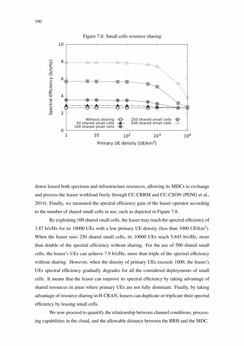
100
Figure 7.8: Small cells resource sharing
0
2
4
6
8
10
1 10 102 103 104
Sp
ect
ral Effi
ciency
[b
/s/H
z]
Primary UE density [UE/km2]
Without sharing50 shared small cells
100 shared small cells
250 shared small cells500 shared small cells
donor leased both spectrum and infrastructure resources, allowing its MDCs to exchange
and process the leaser workload freely through CC-CRRM and CC-CSON (PENG et al.,
2014). Finally, we measured the spectral efficiency gain of the leaser operator according
to the number of shared small cells in use, such as depicted in Figure 7.8.
By exploiting 100 shared small cells, the leaser may reach the spectral efficiency of
3.87 b/s/Hz for its 10000 UEs with a low primary UE density (less than 1000 UE/km2).
When the leaser uses 250 shared small cells, its 10000 UEs reach 5,845 b/s/Hz, more
than double of the spectral efficiency without sharing. For the use of 500 shared small
cells, the leaser’s UEs can achieve 7.9 b/s/Hz, more than triple of the spectral efficiency
without sharing. However, when the density of primary UEs exceeds 1000, the leaser’s
UEs spectral efficiency gradually degrades for all the considered deployments of small
cells. It means that the leaser can improve its spectral efficiency by taking advantage of
shared resources in areas where primary UEs are not fully dominant. Finally, by taking
advantage of resource sharing in H-CRAN, leasers can duplicate or triplicate their spectral
efficiency by leasing small cells.
We now proceed to quantify the relationship between channel conditions, process-
ing capabilities in the cloud, and the allowable distance between the RRH and the MDC.

101
7.2.2 Analyzing the Distance between MDC and RRH in an H-CRAN
First of all, we validated equation (4.8) by comparing its outcome against ex-
perimental work reported in (BHAUMIK et al., 2012). We consider the same scenario
of (BHAUMIK et al., 2012), where a vBBU within an MDC has to decode a code block
from an RRH and, setting the round-trip delay Λ equal to a delay budget Φ, we find the
maximum distance dsm between MDC and RRH.
Table 7.1: Validation parametersValidation parameters Values
un 6144 bits (3rd Generation PartnershipProject (3GPP), 2015)
ω 200 op./bit (HOLMA; TOSKALA,2009)
vs 1 op./cycle (nominal set)c 300 m/µsα 50 kmϖ 20 µs (MUSUMECI et al., 2016)Φ 2.7 ms (BHAUMIK et al., 2012)in 7 recursions (BHAUMIK et al., 2012)psn 3.47 GHz (BHAUMIK et al., 2012)
Validation results Valuesdsm(Experimental) 20 km (BHAUMIK et al., 2012)dsm(Analythical) 20.86 km (4.3% error)
The validation scenario parameters are presented in Table 7.1 and described as fol-
lows: A UE’s code block to be decoded presents un = 6144 bits, the maximum code block
size for LTE (3rd Generation Partnership Project (3GPP), 2015). The decoder has a com-
plexity of ω = 200 operations per bit (HOLMA; TOSKALA, 2009). Considering a single
core processor, we set ω = 1 operation per cycle, providing a direct relation between the
processor clock rate psmn and the total number of operations required to decode the code
block. Based on a typical Brand A – G.652 fiber as the optical medium, we set α = 50
km as the maximum distance that can be covered without a regenerator. We consider an
average node delay of ϖ = 20 µs, as in (MUSUMECI et al., 2016). As in (BHAUMIK
et al., 2012), we set ismn = 7 recursions (fixed) and psn = 3.47 GHz. Finally, we adopt
a delay budget of Φ = 2.7 ms, accounting for code block reply encoding and processing
for the upper layers in the protocol stack (China Mobile Research Institute, 2011; BHAU-
MIK et al., 2012). The result we obtain from equation 4.8 indicates a maximum distance
dsm = 20.86 km between MDC and RRH, within 5% of the distance of 20 km considered
in (BHAUMIK et al., 2012). Also, Φ was reduced of 0.3 ms to represent the code block
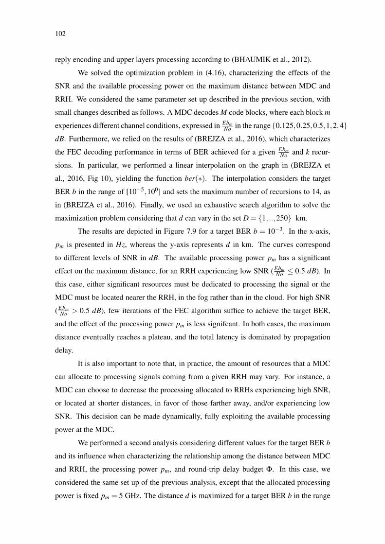
102
reply encoding and upper layers processing according to (BHAUMIK et al., 2012).
We solved the optimization problem in (4.16), characterizing the effects of the
SNR and the available processing power on the maximum distance between MDC and
RRH. We considered the same parameter set up described in the previous section, with
small changes described as follows. A MDC decodes M code blocks, where each block m
experiences different channel conditions, expressed in EbmNo in the range {0.125,0.25,0.5,1,2,4}
dB. Furthermore, we relied on the results of (BREJZA et al., 2016), which characterizes
the FEC decoding performance in terms of BER achieved for a given EbmNo and k recur-
sions. In particular, we performed a linear interpolation on the graph in (BREJZA et
al., 2016, Fig 10), yielding the function ber(∗). The interpolation considers the target
BER b in the range of [10−5,100] and sets the maximum number of recursions to 14, as
in (BREJZA et al., 2016). Finally, we used an exhaustive search algorithm to solve the
maximization problem considering that d can vary in the set D = {1, ..,250} km.
The results are depicted in Figure 7.9 for a target BER b = 10−3. In the x-axis,
pm is presented in Hz, whereas the y-axis represents d in km. The curves correspond
to different levels of SNR in dB. The available processing power pm has a significant
effect on the maximum distance, for an RRH experiencing low SNR (EbmNo ≤ 0.5 dB). In
this case, either significant resources must be dedicated to processing the signal or the
MDC must be located nearer the RRH, in the fog rather than in the cloud. For high SNR
(EbmNo > 0.5 dB), few iterations of the FEC algorithm suffice to achieve the target BER,
and the effect of the processing power pm is less signifcant. In both cases, the maximum
distance eventually reaches a plateau, and the total latency is dominated by propagation
delay.
It is also important to note that, in practice, the amount of resources that a MDC
can allocate to processing signals coming from a given RRH may vary. For instance, a
MDC can choose to decrease the processing allocated to RRHs experiencing high SNR,
or located at shorter distances, in favor of those farther away, and/or experiencing low
SNR. This decision can be made dynamically, fully exploiting the available processing
power at the MDC.
We performed a second analysis considering different values for the target BER b
and its influence when characterizing the relationship among the distance between MDC
and RRH, the processing power pm, and round-trip delay budget Φ. In this case, we
considered the same set up of the previous analysis, except that the allocated processing
power is fixed pm = 5 GHz. The distance d is maximized for a target BER b in the range
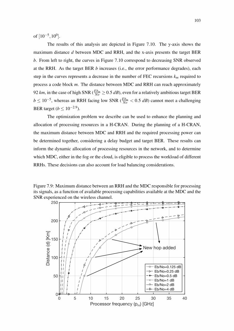
103
of [10−5,100].
The results of this analysis are depicted in Figure 7.10. The y-axis shows the
maximum distance d between MDC and RRH, and the x-axis presents the target BER
b. From left to right, the curves in Figure 7.10 correspond to decreasing SNR observed
at the RRH. As the target BER b increases (i.e., the error performance degrades), each
step in the curves represents a decrease in the number of FEC recursions km required to
process a code block m. The distance between MDC and RRH can reach approximately
92 km, in the case of high SNR (EbmNo ≥ 0.5 dB), even for a relatively ambitious target BER
b ≤ 10−5, whereas an RRH facing low SNR (EbmNo < 0.5 dB) cannot meet a challenging
BER target (b≤ 10−2.9).
The optimization problem we describe can be used to enhance the planning and
allocation of processing resources in a H-CRAN. During the planning of a H-CRAN,
the maximum distance between MDC and RRH and the required processing power can
be determined together, considering a delay budget and target BER. These results can
inform the dynamic allocation of processing resources in the network, and to determine
which MDC, either in the fog or the cloud, is eligible to process the workload of different
RRHs. These decisions can also account for load balancing considerations.
Figure 7.9: Maximum distance between an RRH and the MDC responsible for processingits signals, as a function of available processing capabilities available at the MDC and theSNR experienced on the wireless channel.
104
Figure 7.10: Maximum distance between an RRH and the MDC responsible for process-ing its signals, as a function of the target BER and the SNR experienced on the wirelesschannel.
7.3 Minimizing processing power underusage in H-CRAN
The processing power underusage problem modeled in (4.29) tracks the tradeoff
between processing power consumption reduction and consolidation within the pool of an
H-CRAN. In this case, increasing the weight 0 ≤ al pha ≤ 1 represents prioritizing pro-
cessing power reduction, whereas decreasing it leads to better consolidation, which can
simply be represented in terms of the average number of MDCs active during H-CRAN
operation. Considering this reasoning, we asses both: an optimal offline algorithm de-
rived from the BILP model described in (4.29) and compare to our online solution which
is a greedy decision algorithm shown in Algorithm (3).
Because a BILP is solved through a full combinatorial search algorithm, such as
Simplex, it presents exponential complexity. In this case, to turn the scenario computable,
we created a different scenario with fewer elements. Based on the smallest of the nine
scenarios covered in this thesis, we captured a slice of H-CRAN composed of four MDCs
S = 4 connected to nine RRHs M = 9 that can provide access to nine UEs N = 9 con-
sidering four seconds T = 4 of operation. All the request are randomly created, as well
as the position of the elements. It is important to mention that all the other definitions
from the system model hold for this experiment. Each of the results gathered is measured
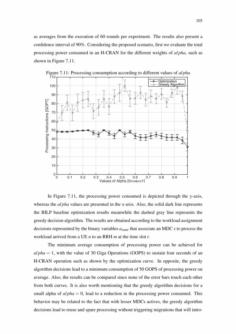
105
as averages from the execution of 60 rounds per experiment. The results also present a
confidence interval of 90%. Considering the proposed scenario, first we evaluate the total
processing power consumed in an H-CRAN for the different weights of al pha, such as
shown in Figure 7.11.
Figure 7.11: Processing consumption according to different values of al pha
Values of Alpha [0<=a<=1]0 0.1 0.2 0.3 0.4 0.5 0.6 0.7 0.8 0.9 1
Pro
ce
ssin
g I
nstr
uctio
ns [
GO
PT
]
0
10
20
30
40
50
60
70
80
90
100
110OptimizationGreedy Algorithm
In Figure 7.11, the processing power consumed is depicted through the y-axis,
whereas the al pha values are presented in the x-axis. Also, the solid dark line represents
the BILP baseline optimization results meanwhile the dashed gray line represents the
greedy decision algorithm. The results are obtained according to the workload assignment
decisions represented by the binary variables asmnt that associate an MDC s to process the
workload arrived from a UE n to an RRH m at the time slot t.
The minimum average consumption of processing power can be achieved for
al pha = 1, with the value of 30 Giga Operations (GOPS) to sustain four seconds of an
H-CRAN operation such as shown by the optimization curve. In opposite, the greedy
algorithm decisions lead to a minimum consumption of 50 GOPS of processing power on
average. Also, the results can be compared since none of the error bars touch each other
from both curves. It is also worth mentioning that the greedy algorithm decisions for a
small alpha of al pha = 0, lead to a reduction in the processing power consumed. This
behavior may be related to the fact that with lesser MDCs actives, the greedy algorithm
decisions lead to reuse and spare processing without triggering migrations that will intro-

106
duce larger consumption of processing power. In this case, to continue our comparison,
we evaluate the average number of active MDCs such as presented in Figure 7.12
Figure 7.12: Average number of active MDCs per second for the biased decisions influ-enced by al pha.
Values of Alpha [0<=a<=1]0 0.1 0.2 0.3 0.4 0.5 0.6 0.7 0.8 0.9 1
Ave
rag
e n
um
be
r o
f a
ctiv
y M
DC
s
0
0.5
1
1.5
2
2.5
3
3.5
4OptimizationGreedy Algorithm
As can be seen in Figure 7.12, the x-axis represents the values of al pha, whereas
the y-axis represents the average number of MDCs that were active during the four sec-
onds of execution of an H-CRAN. For an al pha = 0, the decisions of the baseline lead
to an average of 0.43 MDCs active per second. It means that an H-CRAN can reuse a
single MDC making it active for fewer seconds than the maximum time window to meet
all the UEs requests. Whereas, the decisions are taken by the greedy algorithm lead to
an average of 1,15 at best, which means that sometimes two MDCs must be active in the
same second to meet all requests of the scenario.
Further, for higher values of alpha in Figure 7.12, the baseline decisions lead to
results that behave as a platoon staying almost always in the values of 0,74 MDCs active
per second. The greedy algorithm, in turn, presents decisions that lead to results with
higher variance than the baseline escalating until arriving the value of full usage of MDCs
equals to 4 MDCs active per second for an al pha = 1. To better represent the tradeoff be-
tween consolidation and reduced usage of processing power consumption through better
distribution, we correlate the results of both solutions being presented in Figure 7.13.
As can be seen in Figure 7.13, in the x-axis the average number of MDCs active
are shown. In the y-axis, the total processing power consumed in GOPT is presented.

107
Figure 7.13: Tradeoff between processing power consumption and consolidation in theH-CRAN.
Average MDC on0 0.2 0.4 0.6 0.8 1 1.2 1.4 1.6 1.8 2
Pro
ce
ssin
g I
nstr
uctio
ns [
GO
PT
]
0
10
20
30
40
50
60
70
80
90
Optimization alpha=0Greedy alpha=0Optimization alpha=0.5Greedy alpha=0.5Optimization alpha=1Greedy alpha=1
Also, we paired the results that have the same value of al pha for both approaches with
the same color.
The decisions taken by the BILP optimization show that it is possible to keep a
consolidation of 0.43 MDCs active per second by increasing the total processing con-
sumed from approximately 30 GOPT to 43 GOPT. Whereas, the same is achieved by the
greedy algorithm that can perform at best a consolidation of 1,15 MDCs active per second
required to increase from 60 GOPT to 82 GOPT.
Because operators can either have their infrastructure or lease it from others in H-
CRAN, it is fundamental the understanding of the tradeoff presented to address the under-
usage of processing power. For operators with their infrastructure, consolidation brings
several benefits regarding reduced OPEX and energy consumption decreasing through
reuse. In this case, the operator should address processing power underusage by setting
al pha to lower values near zero. On the other hand, for an operator that leases infras-
tructure in a pay-as-you-go business model, it is essential to decrease the total processing
power in use to reduce the costs with leasing. Therefore, operators leasing infrastructure
must increase the value of alpha when addressing the problem of underusage processing
in H-CRAN. Next, we present our final remarks and conclusions.

108
109
8 CONCLUSIONS
In this thesis, we discussed the benefits of deploying H-CRAN and the different
challenges that arises from its employment, i.e., (i) high intercell interference in the RAN;
(ii) critical delay constraints at the fronthaul; and (iii) poor processing power allocation
in the cloud. To address these challenges a decision making system able to interact across
RAN, fronthaul, and cloud is required. In this case, an architecture is introduced by re-
thinking design principles of SDN to control H-CRAN to influence its decision making
process. Along with this architecture, an API is also introduced standardizing the commu-
nication of controllers with wireless equipments turning feasible their control. On top of
such controllers, different decision algorithms are created to solve the different H-CRAN
challenges.
Given the challenges identified and the proposal of an architecture to logically
centralize the decision making within an H-CRAN based on SDN principles, extensive
research, development, and experimentation have been conducted aiming to verify the
following hypothesis.
Hypothesis: The decisions in an H-CRAN must be taken by an SDN-based system able
to address different challenges considering delay constraints.
The proposed hypothesis is tested through four different case studies. The first
case study has demonstrated the cost introduced by deploying a logically centralize deci-
sion making system based on SDN. This case study presented the deployment of a sim-
ulated H-CRAN scenario based on 3GPP definitions, including different UE and RRHs
densities. The number of messages exchanged and the network overload is calculated
based on the different functions available at the proposed API. We also measured the
capacity and average energy used per RRH to identify the benefits brought by such a sys-
tem even by employing a simple decision algorithm. In the second case study, a decision
algorithm was implemented such that interference is reduced by exploiting infrastructure
spectrum sharing techniques. In the third use case, delay constraints were considered
changing decisions revolving the processing power allocated and the distance between
MDCs and RRHs. Finally, in the fourth case study, the tradeoff of processing power con-
sumption and consolidation regarding active MDCs per second in H-CRAN is exploited
to address underusage of resources in the pool.
The case studies to support the created hypothesis also were fundamental to ad-
dress the three research questions presented in this thesis. The answers to each question

110
are following detailed.
RQ 1 - What relevant information and technology are required to make deci-
sions within an H-CRAN considering RAN, fronthaul, and cloud?
We determined the most relevant information that are required to make deci-
sions within an H-CRAN by exploiting the main challenges identified and creating a API
that can exchange messages containing information from different parts of an H-CRAN.
Whereas, for the technology required to implement an SDN-based decision-making sys-
tem, we presented a table that relate each technology, such as SDR and CoMP, to a re-
sponsibility that a controller from an SDN-based decision-making system must assume.
RQ 2 - What are the main decisions to be taken in an H-CRAN considering
different limitations when adjusting the RAN, fronthaul, and cloud?
The decisions that an SDN-based decision-making system must assume are di-
rectly related to the responsibilities it will have to handle. In this case, considering the
challenges presented in this work, three decisions where deeply investigated. In the first,
an decision algorithm is designed to determine which association of UEs must occur and
with which priority according to the sharing policy in use. In the second, the processing
power allocation is decided by a decision algorithm that considers delay requirements
and distance between MDC and RRH in an H-CRAN. In the third, a decision algorithm
is created to assign the workload from RRHs to a distributed pool of MDCs to enhance
processing power usage and consolidation.
RQ3 - Considering the gathered information can resource be reallocated to
enhance their use for long-term operations considering the limitations inherent of
H-CRAN?
As already studied in this thesis, channel, processing power, and RRH usage can
be changed at runtime to solve issues, such as delay constraints and interference. How-
ever, the underusage of processing power require that workload of RRHs be reallocated
frequently. In this case, a greedy algorithm to assign the workloads within H-CRAN is
proposed to execute decisions during runtime. Also, we shed light on the tradeoff between
consolidation and processing power consumption within the pool being able to address the
problem of processing power underusage considering the different interests of an operator
in H-CRAN.
Based on the studies conducted so far it is possible to identify a few open issues in
the investigated topic, which can be subject of future work. For example, interdependency
of different decision algorithm can be cornerstone for improving performance when dif-
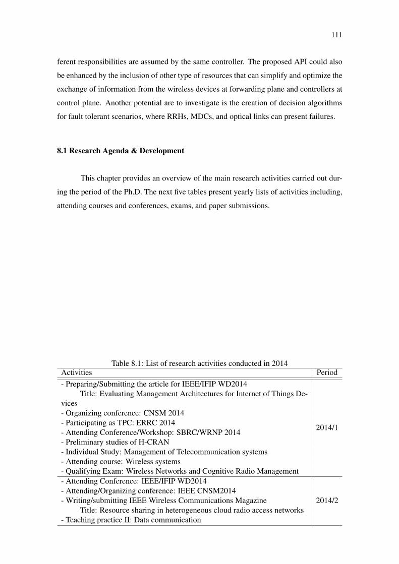
111
ferent responsibilities are assumed by the same controller. The proposed API could also
be enhanced by the inclusion of other type of resources that can simplify and optimize the
exchange of information from the wireless devices at forwarding plane and controllers at
control plane. Another potential are to investigate is the creation of decision algorithms
for fault tolerant scenarios, where RRHs, MDCs, and optical links can present failures.
8.1 Research Agenda & Development
This chapter provides an overview of the main research activities carried out dur-
ing the period of the Ph.D. The next five tables present yearly lists of activities including,
attending courses and conferences, exams, and paper submissions.
Table 8.1: List of research activities conducted in 2014Activities Period- Preparing/Submitting the article for IEEE/IFIP WD2014
2014/1
Title: Evaluating Management Architectures for Internet of Things De-vices- Organizing conference: CNSM 2014- Participating as TPC: ERRC 2014- Attending Conference/Workshop: SBRC/WRNP 2014- Preliminary studies of H-CRAN- Individual Study: Management of Telecommunication systems- Attending course: Wireless systems- Qualifying Exam: Wireless Networks and Cognitive Radio Management- Attending Conference: IEEE/IFIP WD2014
2014/2- Attending/Organizing conference: IEEE CNSM2014- Writing/submitting IEEE Wireless Communications Magazine
Title: Resource sharing in heterogeneous cloud radio access networks- Teaching practice II: Data communication

112
Table 8.2: List of research activities conducted in 2015Activities Period
- Writing/submitting Elsevier Computer Networks
2015/1
Title: Managing Mobile Cloud Computing Considering Objective and
Subjective Perspectives
- Writing project for “Sandwich” internship
- Attending Conference/Workshop: SBRC/WRNP 2015
- Participating as TPC: ERRC 2015
- Start of “Sandwich” internship
2015/2
- Investigating challenges inherent of H-CRAN
- Writing Article
Title: Design Considerations for Software-Defined Wireless Network-
ing in Heterogeneous Cloud Radio Access Networks
Table 8.3: List of research activities conducted in 2016Activities Period
- Investigating delay aspects of an H-CRAN
2016/1
- Writing Article
Title: Characterizing the Relation between Processing Power and Dis-
tance between BBU and RRH in a Cloud RAN
- Implementing H-CRAN scenarios
- End of “Sandwich” internship
2016/2- Investigating Forward Error Correction
- Implementing the simulator considering the deployed scenarios
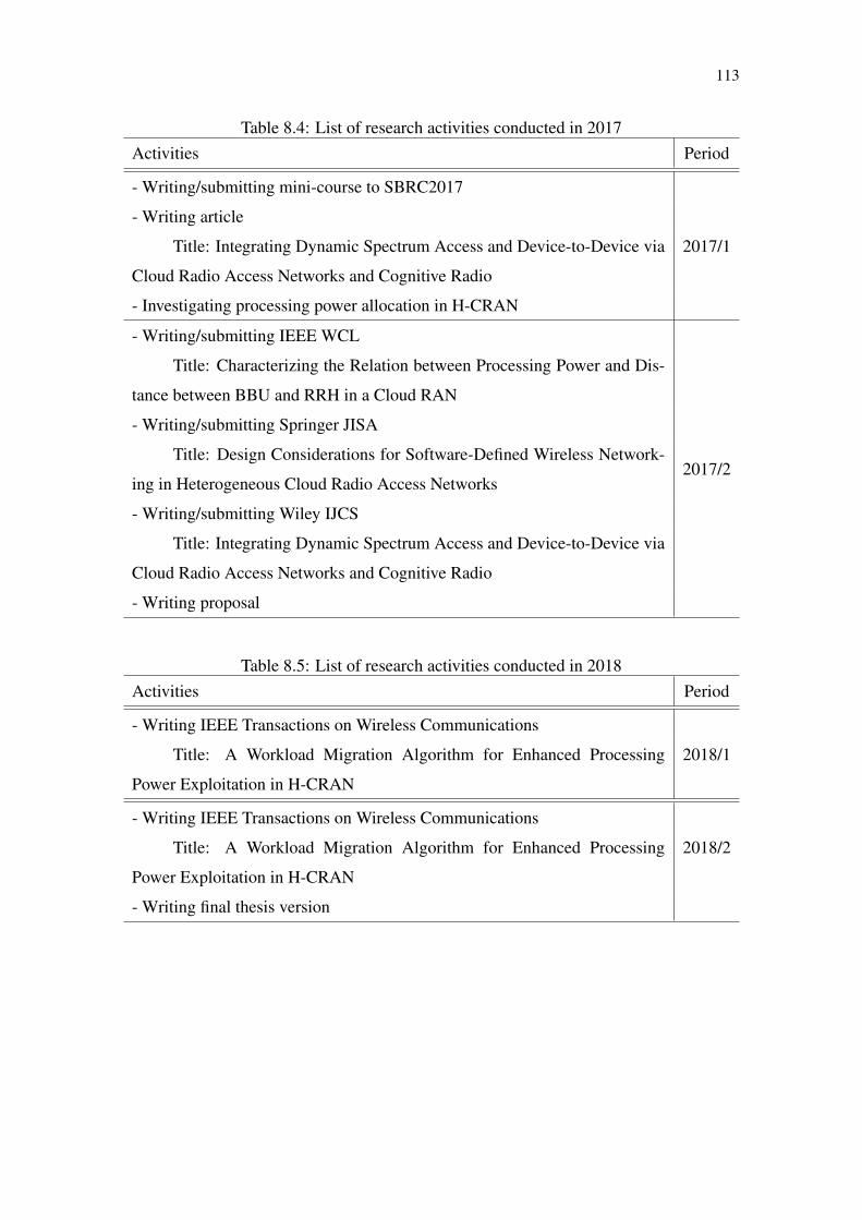
113
Table 8.4: List of research activities conducted in 2017Activities Period
- Writing/submitting mini-course to SBRC2017
2017/1
- Writing article
Title: Integrating Dynamic Spectrum Access and Device-to-Device via
Cloud Radio Access Networks and Cognitive Radio
- Investigating processing power allocation in H-CRAN
- Writing/submitting IEEE WCL
Title: Characterizing the Relation between Processing Power and Dis-
tance between BBU and RRH in a Cloud RAN
2017/2
- Writing/submitting Springer JISA
Title: Design Considerations for Software-Defined Wireless Network-
ing in Heterogeneous Cloud Radio Access Networks
- Writing/submitting Wiley IJCS
Title: Integrating Dynamic Spectrum Access and Device-to-Device via
Cloud Radio Access Networks and Cognitive Radio
- Writing proposal
Table 8.5: List of research activities conducted in 2018Activities Period
- Writing IEEE Transactions on Wireless Communications
2018/1Title: A Workload Migration Algorithm for Enhanced Processing
Power Exploitation in H-CRAN
- Writing IEEE Transactions on Wireless Communications
2018/2Title: A Workload Migration Algorithm for Enhanced Processing
Power Exploitation in H-CRAN
- Writing final thesis version

114

115
REFERENCES
3GPP- Technical Specification Group Services and System Aspects. Service aspects andrequirements for network sharing. 2014. 1–19 p. Version 12.0.0.
3rd Generation Partnership Project (3GPP). 3GPP TR 36.814 - Further Advancementsfor E-UTRA Physical Layer Aspects. Technical Report, v. 9, n. 3, p. 1–104, 2010.Available from Internet: <http://www.qtc.jp/3GPP/Specs/36815-900.pdf>.
3rd Generation Partnership Project (3GPP). LTE; Evolved Universal Terrestrial RadioAccess (E-UTRA); Multiplexing and Channel Coding, (3GPP TS 36.2 .212 version12.6.0 Release 12). Technical Specification, 3GPP, p. 1–95, 2015.
ABOLHASAN, M.; LIPMAN, J.; NI, W.; HAGELSTEIN, B. Software-defined wirelessnetworking: centralized, distributed, or hybrid? IEEE Network, v. 29, n. 4, p. 32–38,2015.
AGYAPONG, P.; IWAMURA, M.; STAEHLE, D.; KIESS, W.; BENJEBBOUR,A. Design Considerations for a 5G Network Architecture. IEEE CommunicationsMagazine, v. 52, n. 11, p. 65–75, nov. 2014.
AKHTAR, A. M.; WANG, X.; HANZO, L. Synergistic spectrum sharing in 5G HetNets:A harmonized SDN-enabled approach. IEEE Communications Magazine, v. 54, n. 1,p. 40–47, 2016.
ALYAFAWI, I.; SCHILLER, E.; BRAUN, T.; DIMITROVA, D.; GOMES, A.; NIKAEIN,N. Critical issues of centralized and cloudified LTE-FDD Radio Access Networks. In:2015 IEEE International Conference on Communications (ICC). [S.l.]: IEEE, 2015.v. 2015-Septe, p. 5523–5528.
AMIN, R.; MARTIN, J. Assessing Performance Gains Through Global Resource Controlof Heterogeneous Wireless Networks. IEEE Transactions on Mobile Computing,v. 15, n. 2, p. 292–305, feb 2016.
AUER, G.; GIANNINI, V.; DESSET, C.; GODOR, I.; SKILLERMARK, P.; OLSSON,M.; IMRAN, M.; SABELLA, D.; GONZALEZ, M.; BLUME, O.; FEHSKE, A. Howmuch energy is needed to run a wireless network? IEEE Wireless Communications,v. 18, n. 5, p. 40–49, oct 2011.
BAI, F.; HELMY, A. A survey of mobility models. Wireless Adhoc Networks.University of Southern California, USA, v. 206, p. 147, 2004.
BANDWIDTH Monitor NG. 2017. [Last access: 27/03/2017]. Available from Internet:<http://sourceforge.net/projects/bwmng/>.
BARTELT, J.; ROST, P.; WUBBEN, D.; LESSMANN, J.; MELIS, B.; FETTWEIS,G. Fronthaul and backhaul requirements of flexibly centralized radio access networks.IEEE Wireless Communications, v. 22, n. 5, p. 105–111, oct 2015.
BERNARDOS, C. J.; OLIVA, A. D. L.; SERRANO, P.; BANCHS, A.; CONTRERAS,L. M.; JIN, H.; ZUNIGA, J. C. An architecture for software defined wireless networking.IEEE Wireless Communication, v. 21, n. 3, p. 52–61, June 2014.
116
BHAUMIK, S.; CHANDRABOSE, S. P.; JATAPROLU, M. K.; KUMAR, G.;MURALIDHAR, A.; POLAKOS, P.; SRINIVASAN, V.; WOO, T. CloudIQ. In:Proceedings of the 18th annual international conference on Mobile computing andnetworking - Mobicom ’12. [S.l.]: ACM Press, 2012. p. 125.
BREJZA, M. F.; LI, L.; MAUNDER, R. G.; AL-HASHIMI, B. M.; BERROU, C.;HANZO, L. 20 Years of Turbo Coding and Energy-Aware Design Guidelines forEnergy-Constrained Wireless Applications. IEEE Communications Surveys &Tutorials, v. 18, n. 1, p. 8–28, 2016.
CARAPELLESE, N.; TORNATORE, M.; PATTAVINA, A. Energy-Efficient BasebandUnit Placement in a Fixed/Mobile Converged WDM Aggregation Network. IEEEJournal on Selected Areas in Communications, v. 32, n. 8, p. 1542–1551, aug 2014.
CARAPELLESE, N.; TORNATORE, M.; PATTAVINA, A.; MILANO, P.; PONZIO, V.Placement of Base-Band Units ( BBUs ) over Fixed / Mobile Converged Multi-StageWDM-PONs. 17th International Conference on Optical Network Design andModeling (ONDM), p. 246–251, 2013.
CHECKO, A.; CHRISTIANSEN, H. L.; YAN, Y.; SCOLARI, L.; KARDARAS, G.;BERGER, M. S.; DITTMANN, L. Cloud RAN for Mobile Networks—A TechnologyOverview. IEEE Communications Surveys & Tutorials, v. 17, n. 1, p. 405–426, 2015.
China Mobile Research Institute. C-RAN The Road Towards Green RAN. 2011.1–44 p. Version 2.5.
COSTA-PéREZ, X.; SWETINA, J.; GUO, T.; MAHINDRA, R.; RANGARAJAN,S. Radio access network virtualization for future mobile carrier networks. IEEECommunications Magazine, v. 51, n. 7, p. 27–35, jul. 2013.
CPRI, Common Public Radio Interface. Interface Specification V7.0. [S.l.]: October,2015.
DAI, B.; YU, W. Sparse Beamforming and User-Centric Clustering for Downlink CloudRadio Access Network. IEEE Access, v. 2, n. 1, p. 1326–1339, 2014.
DAMNJANOVIC, A.; MONTOJO, J.; WEI, Y.; JI, T.; LUO, T.; VAJAPEYAM, M.;YOO, T.; SONG, O.; MALLADI, D. A survey on 3GPP heterogeneous networks. IEEEWireless Communications, v. 18, n. 3, p. 10–21, jun 2011.
DAT, P. T.; KANNO, A.; INAGAKI, K.; KAWANISHI, T. High-Capacity WirelessBackhaul Network Using Seamless Convergence of Radio-over-Fiber and 90-GHzMillimeter-Wave. Journal of Lightwave Technology, v. 32, n. 20, p. 3910–3923, oct2014.
DEMESTICHAS, P.; GEORGAKOPOULOS, A.; KARVOUNAS, D.; TSAGKARIS, K.;STAVROULAKI, V.; LU, J.; XIONG, C.; YAO, J. 5G on the Horizon: Key Challengesfor the Radio-Access Network. IEEE Vehicular Technology Magazine, v. 8, n. 3, p.47–53, sep. 2013.
D´ORO, S.; MAROTTA, M. A.; BOTH, C. B.; DASILVA, L.; PALAZZO, S.Power-efficient resource allocation in c-rans with sinr constraints and deadlines. IEEETransaction on Wireless Communications, 2018. [Submitted].

117
DOYLE, L.; KIBILDA, J.; FORDE, T. K.; DASILVA, L. Spectrum Without Bounds,Networks Without Borders. Proceedings of the IEEE, v. 102, n. 3, p. 351–365, mar2014.
FIELDING, R. T.; TAYLOR, R. N. Principled design of the modern web architecture.ACM Transactions on Internet Technology (TOIT), v. 2, n. 2, p. 115–150, 2002.
FIORANI, M.; ROSTAMI, A.; WOSINSKA, L.; MONTI, P. Transport AbstractionModels for an SDN-Controlled Centralized RAN. IEEE Communications Letters,v. 19, n. 8, p. 1406–1409, aug 2015.
GERASIMENKO, M.; MOLTCHANOV, D.; FLOREA, R.; ANDREEV, S.;KOUCHERYAVY, Y.; HIMAYAT, N.; YEH, S.-p.; TALWAR, S. Cooperative RadioResource Management in Heterogeneous Cloud Radio Access Networks. IEEE Access,v. 3, n. 1, p. 397–406, 2015.
GOMEZ-MIGUELEZ, I.; AVDIC, E.; MARCHETTI, N.; MACALUSO, I.; DOYLE,L. Cloud-RAN platform for LSA in 5G networks: Tradeoff within the infrastructure.In: International Symposium on Communications, Control and Signal Processing(ISCCSP). [S.l.: s.n.], 2014. p. 522–525.
GUAN, B.; HUANG, X.; WU, G.; CHAN, C.; UDAYAN, M.; NEELAM, C. A PoolingPrototype for the LTE MAC Layer Based on a GPP Platform. In: 2015 IEEE GlobalCommunications Conference (GLOBECOM). [S.l.: s.n.], 2014. p. 1–7.
HASTAD, J.; JUST, B.; LAGARIAS, J. C.; SCHNORR, C. P. Polynomial TimeAlgorithms for Finding Integer Relations among Real Numbers. SIAM Journal onComputing, v. 18, n. 5, p. 859–881, oct 1989.
HOLMA, H.; TOSKALA, A. LTE for UMTS-OFDMA and SC-FDMA based RadioAccess. [S.l.]: John Wiley & Sons, 2009.
I, C.-L.; HUANG, J.; DUAN, R.; CUI, C.; JIANG, J. X.; LI, L. Recent Progress onC-RAN Centralization and Cloudification. IEEE Access, v. 2, p. 1030–1039, 2014.
IEEE. Standard for Information technology–Telecommunications and informationexchange between systems Local and metropolitan area networks–Specificrequirements Part 11: Wireless LAN Medium Access Control (MAC) and PhysicalLayer (PHY) Specifications. [S.l.: s.n.], 2012. 2793 p.
IPERF. 2017. [Last access: 27/03/2017]. Available from Internet: <https://iperf.fr/>.
JARSCHEL, M.; ZINNER, T.; HOSSFELD, T.; TRAN-GIA, P.; KELLERER, W.Interfaces, attributes, and use cases: A compass for SDN. IEEE CommunicationsMagazine, v. 52, n. 6, p. 210–217, jun 2014.
Kan Zheng; Fanglong Hu; Wenbo Wang; Wei Xiang; DOHLER, M. Radio resourceallocation in LTE-advanced cellular networks with M2M communications. IEEECommunications Magazine, v. 50, n. 7, p. 184–192, jul 2012.
KANG, X.; ZHANG, R.; MOTANI, M. Price-based resource allocation for spectrum-sharing femtocell networks: A stackelberg game approach. IEEE Journal on SelectedAreas in Communications, v. 30, n. 3, p. 538–549, 2012.
118
KIBILDA, J.; Di Francesco, P.; MALANDRINO, F.; DASILVA, L. A. Infrastructure andspectrum sharing trade-offs in mobile networks. In: IEEE International Symposium onDynamic Spectrum Access Networks (DySPAN). [S.l.: s.n.], 2015. p. 348–357.
KU, Y.-j.; LIN, D.-y.; LEE, C.-f.; HSIEH, P.-j.; WEI, H.-y.; CHOU, C.-t.; PANG,A.-c. 5G Radio Access Network Design with the Fog Paradigm: Confluence ofCommunications and Computing. IEEE Communications Magazine, v. 55, n. 4, p.46–52, apr 2017.
LEARNED, R. E.; JOHNSTON, S. E.; KAMINSKI, N. J. Cognitive coexistence: Athroughput study of mud-enhanced opportunistic spectrum access. In: IEEE Signals,Systems and Computers, 2013 Asilomar Conference on. [S.l.: s.n.], 2013. p.1455–1462.
LEE, Y. L.; LOO, J.; CHUAH, T. C. A new network slicing framework for multi-tenantheterogeneous cloud radio access networks. In: IEEE International Conference onAdvances in Electrical, Electronic and Systems Engineering (ICAEES). [S.l.: s.n.],2016. p. 414–420.
LIANG, C.; YU, F. R. Wireless network virtualization: A survey, some research issuesand challenges. IEEE Communications Survey & Tutorials, v. 1, n. 99, p. 1–24,August 2014.
LIANG, K.; ZHAO, L.; CHU, X.; CHEN, H.-h. An Integrated Architecture for SoftwareDefined and Virtualized Radio Access Networks with Fog Computing. IEEE Network,v. 31, n. 1, p. 80–87, jan 2017.
LIN, P.; JIA, J.; ZHANG, Q.; HAMDI, M. Cooperation among wireless serviceproviders: opportunity, challenge, and solution [Dynamic Spectrum Management. IEEEWireless Communications, v. 17, n. 4, p. 55–61, aug. 2010.
LIU, J.; ZHOU, S.; GONG, J.; NIU, Z.; XU, S. Graph-based framework for flexiblebaseband function splitting and placement in C-RAN. In: 2015 IEEE InternationalConference on Communications (ICC). [S.l.: s.n.], 2015. v. 2015-Septe, p. 1958–1963.
LOPEZ-PEREZ, D.; GUVENC, I.; ROCHE, G. de la; KOUNTOURIS, M.; QUEK, T.;ZHANG, J. Enhanced intercell interference coordination challenges in heterogeneousnetworks. IEEE Wireless Communications, v. 18, n. 3, p. 22–30, June 2011.
LUOTO, P.; PIRINEN, P.; BENNIS, M.; SAMARAKOON, S.; SCOTT, S.; LATVA-AHO, M. Co-Primary Multi-Operator Resource Sharing for Small Cell Networks. IEEETransactions on Wireless Communications, v. 14, n. 6, p. 3120–3130, jun 2015.
MAROTTA, M. A.; AHMADI, H.; ROCHOL, J.; DASILVA, L.; BOTH, C. B.Characterizing the Relation Between Processing Power and Distance Between BBU andRRH in a Cloud RAN. IEEE Wireless Communications Letters, v. 7, n. 3, p. 472–475,jun 2018.
MAROTTA, M. A.; FAGANELLO, L. R.; KIST, M.; BONDAN, L.; WICKBOLDT,J. A.; GRANVILLE, L. Z.; ROCHOL, J.; BOTH, C. B. Integrating dynamic spectrumaccess and device-to-device via cloud radio access networks and cognitive radio. WileyInternational Journal of Communication Systems, v. 31, n. 11, p. e3698, 2018.
119
MAROTTA, M. A.; KAMINSKI, N.; GOMEZ-MIGUELEZ, I.; GRANVILLE, L. Z.;ROCHOL, J.; DASILVA, L.; BOTH, C. B. Resource sharing in heterogeneous cloudradio access networks. IEEE Wireless Communications, v. 22, n. 3, p. 74–82, jun 2015.
MAROTTA, M. A.; KIST, M.; WICKBOLDT, J. A.; GRANVILLE, L. Z.; ROCHOL,J.; BOTH, C. B. Design considerations for software-defined wireless networking inheterogeneous cloud radio access networks. Springer Journal of Internet Services andApplications, v. 8, n. 1, p. 18, dec 2017.
MATINMIKKO, M.; OKKONEN, H.; PALOLA, M.; YRJOLA, S.; AHOKANGAS, P.;MUSTONEN, M. Spectrum sharing using licensed shared access: the concept and itsworkflow for LTE-advanced networks. IEEE Wireless Communications, v. 21, n. 2, p.72–79, abr. 2014.
MUSUMECI, F.; BELLANZON, C.; CARAPELLESE, N.; TORNATORE, M.;PATTAVINA, A.; GOSSELIN, S. Optimal BBU Placement for 5G C-RAN DeploymentOver WDM Aggregation Networks. Journal of Lightwave Technology, v. 34, n. 8, p.1963–1970, apr 2016.
OPENNET. 2017. [Last access: 27/03/2017]. Available from Internet: <https://github.com/dlinknctu/OpenNet/>.
OSSEIRAN, A.; BOCCARDI, F.; BRAUN, V.; KUSUME, K.; MARSCH, P.;MATERNIA, M.; QUESETH, O.; SCHELLMANN, M.; SCHOTTEN, H.; TAOKA,H.; TULLBERG, H.; UUSITALO, M. a.; TIMUS, B.; FALLGREN, M. Scenariosfor 5G mobile and wireless communications: the vision of the METIS project. IEEECommunications Magazine, v. 52, n. 5, p. 26–35, may 2014.
PANCHAL, J. S.; YATES, R. D.; BUDDHIKOT, M. M. Mobile Network ResourceSharing Options: Performance Comparisons. IEEE Transactions on WirelessCommunications, v. 12, n. 9, p. 4470–4482, sep. 2013.
PENG, M.; LI, Y.; JIANG, J.; LI, J.; WANG, C. Heterogeneous cloud radio accessnetworks: a new perspective for enhancing spectral and energy efficiencies. IEEEWireless Communications, v. 21, n. 6, p. 126–135, dec 2014.
PENG, M.; LI, Y.; ZHAO, Z.; WANG, C. System architecture and key technologies for5g heterogeneous cloud radio access networks. Network, IEEE, v. 29, n. 2, p. 6–14,March 2015.
PENG, M.; XIE, X.; HU, Q.; ZHANG, J.; POOR, H. V. Contract-Based InterferenceCoordination in Heterogeneous Cloud Radio Access Networks. IEEE Journal onSelected Areas in Communications, v. 33, n. 6, p. 1140–1153, jun 2015.
PENG, M.; YAN, S.; ZHANG, K.; WANG, C. Fog-computing-based radio accessnetworks: issues and challenges. IEEE Network, v. 30, n. 4, p. 46–53, jul 2016.
PENG, M.; ZHANG, K.; JIANG, J.; WANG, J.; WANG, W. Energy-Efficient ResourceAssignment and Power Allocation in Heterogeneous Cloud Radio Access Networks.IEEE Transactions on Vehicular Technology, v. 64, n. 11, p. 5275–5287, nov 2015.
PENTIKOUSIS, K.; WANG, Y.; HU, W. MobileFlow: Toward Software-Defined MobileNetworks. IEEE Communications Magazine, v. 51, n. 7, p. 44–53, July 2013.

120
PROJECT Floodlight. 2017. [Last access: 27/03/2017]. Available from Internet:<http://www.projectfloodlight.org/floodlight>.
QIAN, M.; HARDJAWANA, W.; SHI, J.; VUCETIC, B. Baseband Processing UnitsVirtualization for Cloud Radio Access Networks. IEEE Wireless CommunicationsLetters, v. 4, n. 2, p. 189–192, apr 2015.
RIGHI, R. d. R.; RODRIGUES, V. F.; COSTA, C. A. da; GALANTE, G.; BONA,L. C. E. de; FERRETO, T. AutoElastic: Automatic Resource Elasticity for HighPerformance Applications in the Cloud. IEEE Transactions on Cloud Computing, v. 4,n. 1, p. 6–19, jan 2016.
ROST, P.; BERNARDOS, C. Cloud technologies for flexible 5G radio access networks.IEEE Communications Magazine, v. 52, n. 5, p. 68–76, 2014.
SCHIMUNECK, M. A. K.; KIST, M.; ROCHOL, J.; RIBEIRO-TEIXEIRA, A. C.;BOTH, C. B. Adaptive Monte Carlo algorithm to global radio resources optimizationin H-CRAN. In: 2017 IEEE International Conference on Communications (ICC).[S.l.]: IEEE, 2017. p. 1–6.
SELIM, M.; KAMAL, A. E.; ELSAYED, K.; ABDEL-ATTY, H. M.; ALNUEM,M. Fronthaul cell outage compensation for 5G networks. IEEE CommunicationsMagazine, v. 54, n. 8, p. 169–175, aug 2016.
TANG, J.; TAY, W. P.; QUEK, T. Q. S. Cross-Layer Resource Allocation With ElasticService Scaling in Cloud Radio Access Network. IEEE Transactions on WirelessCommunications, v. 14, n. 9, p. 5068–5081, sep 2015.
TANG, J.; TAY, W. P.; QUEK, T. Q. S.; LIANG, B. System Cost Minimization inCloud RAN With Limited Fronthaul Capacity. IEEE Transactions on WirelessCommunications, v. 16, n. 5, p. 3371–3384, may 2017.
TARTARINI, L.; MAROTTA, M. A.; CERQUEIRA, E.; ROCHOL, J.; BOTH,C. B.; GERLA, M.; BELLAVISTA, P. Software-defined handover decision engine forheterogeneous cloud radio access networks. Computer Communications, v. 115, n. 1,p. 21–34, jan 2018.
THYAGATURU, A. S.; MERCIAN, A.; MCGARRY, M. P.; REISSLEIN, M.;KELLERER, W. Software Defined Optical Networks (SDONs): A ComprehensiveSurvey. IEEE Communications Surveys & Tutorials, v. 18, n. 4, p. 2738–2786, 2016.
VLC’S stream output. 2017. [Last access: 27/03/2017]. Available from Internet: <https://wiki.videolan.org/Documentation:Streaming_HowTo/Command_Line_Examples/>.
WANG, C.; WANG, Y.; GONG, C.; WAN, Y.; CAI, L.; LUO, Q. A study on virtualBS live migration: A seamless and lossless mechanism for virtual BS migration. In:2013 IEEE 24th Annual International Symposium on Personal, Indoor, and MobileRadio Communications (PIMRC). [S.l.]: IEEE, 2013. p. 2803–2807.
WANG, W.; CHEN, Y.; ZHANG, Q.; JIANG, T. A software-defined wireless networkingenabled spectrum management architecture. IEEE Communications Magazine, v. 54,n. 1, p. 33–39, jan 2016.

121
WICKBOLDT, J.; JESUS, W. D.; ISOLANI, P.; BOTH, C.; ROCHOL, J.; GRANVILLE,L. Software-Defined Networking: Management Requirements and Challenges. IEEECommunications Magazine, v. 53, n. 1, p. 278–285, 2015.
WUBBEN, D.; ROST, P.; BARTELT, J. S.; LALAM, M.; SAVIN, V.; GORGOGLIONE,M.; DEKORSY, A.; FETTWEIS, G. Benefits and Impact of Cloud Computing on 5GSignal Processing: Flexible centralization through cloud-RAN. IEEE Signal ProcessingMagazine, v. 31, n. 6, p. 35–44, nov. 2014.
YANG, H.; ZHANG, J.; JI, Y.; LEE, Y. C-RoFN: Multi-stratum resources optimizationfor cloud-based radio over optical fiber networks. IEEE Communications Magazine,v. 54, n. 8, p. 118–125, 2016.
YANG, M.; LI, Y.; JIN, D.; ZENG, L.; WU, X.; VASILAKOS, A. V. Software-Definedand Virtualized Future Mobile and Wireless Networks: A Survey. Mobile Networks andApplications, v. 20, n. 1, p. 4–18, feb 2015.
ZHANG, H.; CHU, X.; GUO, W.; WANG, S. Coexistence of Wi-Fi and heterogeneoussmall cell networks sharing unlicensed spectrum. IEEE Communications Magazine,v. 53, n. 3, p. 158–164, mar 2015.
ZHANG, Y.; WANG, Y.; FAN, B. SDN Based Optimal User Cooperation and EnergyEfficient Resource Allocation in Cloud Assisted Heterogeneous Networks. IEEE Access,v. 5, n. 1, p. 1469–1481, 2017.

122

123
APPENDIX A — PUBLISHED ARTICLES
This appendix presents the articles published since the beginning of the doctor-
ate. Theses articles are papers resulted from the investigations about H-CRAN and the
SDN-based decision-making system. These papers also present the proposed architecture
that was shown in details in this thesis. Finally, these articles also present the perfor-
mance evaluation of an SDN-based decision-making system in H-CRAN when compared
to traditional cellular networks.
• Title: Resource sharing in heterogeneous cloud radio access networks.
• Authors: MAROTTA, M. A. ; KAMINSKI, N. ; GRANVILLE, L. Z. ; RO-
CHOL, J. ; DASILVA, L. ; BOTH, C. B..
• Journal: IEEE Wireless Communications.
• DOI/URL: https://doi.org/10.1109/MWC.2015.7143329.
• Date: July, 2015.
• Title: Design Considerations for Software-Defined Wireless Networking in Hetero-
geneous Cloud Radio Access Networks.
• Authors: MAROTTA, M. A., KIST, M.; WICKBOLDT, J. A.; GRANVILLE,
L. Z.; ROCHOL, J.; BOTH, C. B..
• Journal: Springer Journal of Internet Services and Applications (JISA).
• DOI/URL: https://doi.org/10.1186/S13174-017-0068-X.
• Date: November, 2017.
• Title: Characterizing the Relation between Processing Power and Distance between
BBU and RRH in a Cloud RAN.
• Authors: MAROTTA, M. A., AHMADI, H.; ROCHOL, J.; DASILVA, L.;
BOTH, C. B..
• Journal: IEEE Wireless Communications Letters (WCL).
• DOI/URL: http://dx.doi.org/10.1109/LWC.2017.2786226
• Date: December, 2017.
• Title: Integrating Dynamic Spectrum Access and Device-to-Device Communica-
tion via Cloud Radio Access Networks and Cognitive Radio.
• Authors: MAROTTA, M. A., FAGANELO, L. R., KIST, M.; BONDAN, L.,

124
WICKBOLDT, J. A.; GRANVILLE, L. Z.; ROCHOL, J.; BOTH, C. B..
• Journal: WILEY International Journal of Communication Systems (IJCS).
• DOI/URL: https://doi.org/10.1002/dac.3698.
• Date: march, 2018

125
APPENDIX B — CORRELATED PUBLISHED ARTICLES
This appendix presents articles that were written during the doctorate. Although
these articles are not directly related to the theme of this thesis, they are still part of the
doctorate and represent marginal results of other activities.
• Title: Evaluating Management Architectures for Internet of Things Devices.
• Authors: MAROTTA, M. A., BOTH, C. B., ROCHOL, J., GRANVILLE, L.
Z., Tarouco, L. M. R..
• Conference: IFIP/IEEE Wireless Days.
• DOI/URL: https://doi.org/10.1109/WD.2014.7020811.
• Date: November 12-14, 2014.
• Location: Rio de Janeiro, Brazil.
• Title: Managing Mobile Cloud Computing Considering Objective and Subjective
Perspectives.
• Authors: MAROTTA, M. A. ; FAGANELLO, L. R.; SCHIMUNECK, M. A.
K.; GRANVILLE, L. Z.; ROCHOL, J.; BOTH, C. B..
• Journal: Elsevier Computer Networks (COMNET).
• DOI/URL: https://doi.org/10.1016/j.comnet.2015.09.040.
• Date: September, 2015.

126
127
APPENDIX C — CO-AUTHORED PUBLISHED ARTICLES
This appendix presents articles that were co-authored during the doctorate. These
articles could be divided into (i) articles related to this thesis and (ii) marginal results from
cooperation with other researchers. This division is shown next.
Co-authored articles related to this thesis
• Title: Impact of Fog and Cloud Computing on an IoT Service Running over an
Optical/Wireless Network Testbed.
• SILVA, A., ABREU, B. , SILVA, E. B., CARVALHO, M., NUNES, M.,
MAROTTA, M. A., HAMMAD, A., PINHEIRO, J. F. N., BOTH, C. B.,
MARQUEZ-BARJA, J. M., DASILVA, L., AND E SILVA, C. F. M..
• Workshop: IEEE INFOCOM International Workshop on Computer and Net-
working Experimental Research Using Testbeds (CNERT 17).
• DOI/URL: https://doi.org/10.1109/INFCOMW.2017.8116434.
• Date: 1-4 May 2017.
• Location: Atlanta, USA.
• Title: Caracterizando Estratégias de Domınio Espacial para Gerenciamento de
Regras em Redes Definidas por Software (in Portuguese).
• Authors: DE ARAÚJO, G., MAROTTA, M. A., WICKBOLDT, J., BOTH, C.,
GASPARY, L., ROCHOL, J. AND GRANVILLE, L.
• Conference: XXXV Simpósio Brasileiro de Redes de Computadores (SBRC
2017).
• Date: 15-19 May 2017.
• Location: Belém, Brazil.
• Title: Software-Defined Handover Decision Engine for Heterogeneous Cloud Ra-
dio Access Networks.
• Authors: TARTARINI, L.; MAROTTA, M. A.; CERQUEIRA, E.; ROCHOL,
J.; BOTH, C. B.; GERLA, M.; BELLAVISTA, P..
• Journal: Elsevier Computer Communications (ComCom).
• DOI/URL: https://doi.org/10.1016/j.comcom.2017.10.018.
• Date: January, 2018.

128
Co-authored articles not directly related to this thesis
• Title: Adaptive Threshold Architecture for Spectrum Sensing in Public Safety Radio
Channels.
• Authors: BONDAN, L., MAROTTA, M. A., KIST, M., FAGANELLO, L. R.,
BOTH, C. B., ROCHOL, J., GRANVILLE, L. Z.
• Conference: IEEE Wireless Communications and Networking Conference
(WCNC).
• DOI/URL: https://doi.org/10.1109/WCNC.2015.7127484.
• Date: May 2014.
• Location: New Orleans, LA, USA.
• Title: ChiMaS: A Spectrum Sensing-based Channels Classification System for Cog-
nitive Radio Networks.
• BONDAN, L., MAROTTA, M.A., FAGANELLO, L.R., ROCHOL, J. AND
GRANVILLE, L.Z..
• Conference: IEEE Wireless Communications and Networking Conference
(WCNC).
• DOI/URL: https://doi.org/10.1109/WCNC.2016.7564911.
• Date: April, 2016.
• Location: Doha, Qatar.