FROM CONCEPT TO PERFORMANCE - kepner.com · Hydraulic and Pneumatic In-line and Cartridge Insert...
84
Hydraulic and Pneumatic In-line and Cartridge Insert Control Valves for any fluid or gas. Kepner Products Company: 995 North Ellsworth Avenue, Villa Park, Illinois 60181 630-279-1550 FAX 630-279-9669 www.kepner.com FROM CONCEPT TO PERFORMANCE... KEPNER VALVES DELIVER ZERO LEAKAGE CONTROL! 2010 TECHNICAL CATALOG
-
Upload
nguyenmien -
Category
Documents
-
view
212 -
download
0
Transcript of FROM CONCEPT TO PERFORMANCE - kepner.com · Hydraulic and Pneumatic In-line and Cartridge Insert...

Hydraulic and Pneumatic In-line and Cartridge Insert Control Valves for
any fluid or gas.
Kepner Products Company: 995 North Ellsworth Avenue, Villa Park, Illinois 60181630-279-1550 FAX 630-279-9669
www.kepner.com
FROM CONCEPT TO PERFORMANCE...KEPNER VALVES DELIVERZERO LEAKAGE CONTROL!
2010 TECHNICAL CATALOG

More than 60 years in businessand continuous improvement are your assurance
of the best in product performance.
RELIABILITY SINCE 1948 We've been designing and producing control valves that out-deliverand outlast the competition. Our secret? Simple; we focus on basic concepts to provide the bestcheck valves in the industry. You face a myriad of design challenges in your product. Specify thecheck valve you can rely on.
QUALITY...EVERY TIME Kepner valves are engineered and manufactured to the highest possiblestandards, ensuring they work when you need them to and for years to come.
AVAILABILITY We don't just have the best products. We utilize manufacturing and schedulingtechniques to provide them when you need them. Our customer support... staffed by personnelwith many years of experience...is there to provide assistance and answer questions quickly.
� 2010 Kepner Products Company

Inline Valves
● Check and Relief Check Valves● Adjustable Relief Valves● High Pressure Check/Relief Check Valves● Ball Check Valves ● Shuttle Valves● Fixed Orifice Flow Restrictor Valves● Split Flange Check Valves
Cartridge Type Insert Versions
● Cartridge Check and Relief Check Valves● Cartridge Adjustable Relief Valves ● Cartridge Shuttle Valves● Cartridge Lock Valves● Pneumatic Cartridge Lock Valves
Lock Valves
● Single Lock Valves● Pneumatic Single Lock Valves● Dual Lock Valves
Products and General Information
● O-Ring Specification Guide● Application and Product Suitability● Material Selection and Safety● Flow Coefficients● Approximate Valve Weights● Standard Terms and Conditions of Sale● Web Site Information
� Technical Catalog Supplement - Tips and Applications
995 N. Ellsworth AvenueVilla Park, IL 60181
Phone: 630-279-1550FAX: 630-279-9669
www.kepner.com

995 N. Ellsworth AvenueVilla Park, IL 60181
Phone: 630-279-1550FAX: 630-279-9669
www.kepner.com
The Kepner Flexible Seal Seat� designoffers positive leakage control of liquid or gas.The seat design is a carefully engineeredcombination of metal-to-metal and resilientO-Ring seal contact. The O-Ring is securelyretained at the seat rather than on the pop-pet, protecting it from the destructive abrad-ing and blasting effect of the flow; seal life isextended. Seat “wire drawing” common toconventional valves has been eliminated by
CLOSED: Relaxed O-Ring seal and gentle seal-to-poppet contact guarantees(No Flow) low pressure sealing and eliminates valve chatter.
OPEN: Seal flexes to close off all external leakage around end cap. (Full Flow) Enclosure protects O-Ring seal, prevents seal displacement.
CLOSED: Seal still holding external leakage now also flexes around poppet.(Reverse Higher pressures tighten the seal. Bubble-tight shutoff.Checked)
CLOSED OPEN CLOSEDNo Flow Full Flow Reverse Flow Checked
u LEAK TIGHT SEALING
u POSITIVE ACTION EVEN AT LOW PRESSURE
u FREEDOM FROM CHATTER
�
Our unique Flexible Seal Seat�
assures bubble-tight performance.
the Flexible Seal Seat� design. The sealcloses around scratches, dents, and otherirregularities and effectively prevents anyleakage past the seat. A wide choice of O-Ring seal elastomers is offered for systemcompatibility. The Flexible Seal Seat�design is available in check, relief, shuttle,and pilot operated check valves, and hasbeen successfully applied to millions of fluidcontrol situations.

Inline Check and Relief Check Valves
These spring-operated poppet valves, with optional relief settings, allow free flow in only onedirection and prevent backflow - sometimes referred to as “backflow preventor”, “flow stop”, or“non-return” valve. They are also used for relief and bypass functions.
Kepner’s Flexible Seal Seat� combines metal-to-metal contact with a resilient seal seat ensuringdependable bubble-tight shutoff of liquid or gas, and long service life. Standard and specialtyvalve designs handle a wide variety of applications.
Features and Benefits:
● Flexible Seal SeatTM
for zero leakage (bubble-tight) sealing at low and high pressures.
● O-Ring seal positively secured.● Non-pressurized threads.● Poppet stop inside valve body prevents spring from bottoming out.● Generous flow passages allow full flow with minimal pressure drop.
Valve Specifications:
● Port Configurations: Pipe or Tube (NPT, JIC; 12 Combinations)● Port Sizes: 1/8 inch to 3 inch (3.2 mm to 76 mm)● Body Materials: Aluminum, Brass, Steel, 303 or 316 Stainless Steel● O-Ring Seals: Buna-N, Neoprene, Teflon®, Viton�, EP, others available● Temperature: -300�F to 450�F (-184�C to 232�C), O-Ring dependent● Check Crack Pressure: 1 - 2 PSI (.07 bar to .14 bar)● Relief/Check Crack Pressures: 5 PSI (.35 bar), 10 PSI (0.7 bar), 25 PSI
(1.7 bar), 50 PSI (3.5 bar) and 65 PSI (4.5 bar), others available● Operating Pressure: to 3,000 PSI (207 bar)● Flow: to 500 GPM (1893 LPM)
995 N. Ellsworth AvenueVilla Park, IL 60181
Phone: 630-279-1550FAX: 630-279-9669
www.kepner.com
Consult Factory or Distributor for more help. Customer/user is solely responsible to select products suitable for their specific application requirements
and to ensure proper installation, operation and maintenance of these products. Improper selection or use of products can cause personal injury or
property damage. All sales are subject to Kepner Products Company Standard Terms and Conditions of Sale. Design subject to change without notice.

19 IJIC - IJIC 7 JIC - MPT
17 JIC - IJIC 5 MPT - JIC
15 IJIC - JIC 4 FPT - FPT
13 JIC - JIC 3 MPT - MPT
11 JIC - FPT 2 FPT - MPT
9 FPT - JIC 1 MPT - FPT
IJIC IJIC JIC MPTTUBE TO TUBE TUBE TO PIPE
JIC IJIC MPT JICTUBE TO TUBE PIPE TO TUBE
IJIC JIC FPT FPTTUBE TO TUBE PIPE TO PIPE
PART NUMBER EXAMPLE4 06 C - 1 - 25
JIC JIC MPT MPTTUBE TO TUBE PIPE TO PIPE
JIC FPT FPT MPTTUBE TO PIPE PIPE TO PIPE
FPT JIC MPT FTPPIPE TO TUBE PIPE TO PIPE
PORT CONFIGURATIONS
Part Numbers: Fixed Settings 1/8” to 3” sizes
PORT SIZES
04 = 1/8 PIPE - 1/4 TUBE 16 = 1” PIPE - 1” TUBE 06 = 1/4 PIPE - 3/8 TUBE 20 = 1 1/4 PIPE - 1 1/4 TUBE08 = 3/8 PIPE - 1/2 TUBE 24 = 1 1/2 PIPE - 1 1/2 TUBE10 = 1/2 PIPE - 5/8 TUBE 32 = 2” PIPE - 2” TUBE12 = 3/4 PIPE - 3/4 TUBE 48 = 3” PIPE (CONSULT FACTORY)
CONSTRUCTION MATERIALS
A = ALUMINUM D = 303 STAINLESS STEELB = BRASS i F = 316 STAINLESS STEELC = STEEL
O-RING SEALS
1 = BUNA-N 3* = TEFLON®
9 = NEOPRENE 18 = VITON®
25 = ETHYLENE PROPYLENE
OTHERS AVAILABLE
CRACK PRESSURE
“Blank”= 1-2 PSICRACK (Standard)5 = 5 PSI CRACK
10 = 10 PSI CRACK 25 = 25 PSI CRACK 50 = 50 PSI CRACK 65 = 65 PSI CRACK
OTHERS AVAILABLE
Inline Check and Relief Check Valves
995 N. Ellsworth AvenueVilla Park, IL 60181
Phone: 630-279-1550FAX: 630-279-9669
www.kepner.com
Consult Factory or Distributor for more help.
Customer/user is solely responsible to select products
suitable for their specific application requirements and to
ensure proper installation, operation and maintenance of
these products. Improper selection or use of products
can cause personal injury or property damage. All sales
are subject to Kepner Products Company Standard
Terms and Conditions of Sale. Design subject to change
without notice.

Inline Check and Relief Check Valves
Flow Charts: Sizes 1/8” - 1”
Curves indicate Pressure Drop vs Flow Rate
FLOW - GALLONS PER MINUTE
Test Fluid: Water Test Temp: 50oF
PR
ES
SU
RE
DR
OP
- P
SI
SIZE CONNECTIONS
04 1/8” Pipe or 1/4” Tube
06 1/4” Pipe or 3/8” Tube
08 3/8” Pipe or 1/2” Tube
10 1/2” Pipe or 5/8” Tube
12 3/4” Pipe or 3/4” Tube
16 1” Pipe or 1” Tube
PR
ES
SU
RE
DR
OP
- P
SI
FLOW - GALLONS PER MINUTETest Fluid: MIL-H-5606A HYDRAULIC OIL Test Temp: 70o F
EXAMPLE WITH VARIOUS RELIEF SETTINGS
995 N. Ellsworth AvenueVilla Park, IL 60181
Phone: 630-279-1550FAX: 630-279-9669
www.kepner.com
Consult Factory or Distributor for more help. Customer/user
is solely responsible to select products suitable for their
specific application requirements and to ensure proper
installation, operation and maintenance of these products.
Improper selection or use of products can cause personal
injury or property damage. All sales are subject to Kepner
Products Company Standard Terms and Conditions of Sale.
Design subject to change without notice.

Curves indicate Pressure Drop vs Flow Rate
PR
ES
SU
RE
DR
OP
- P
SI
SIZES: 1-1/4” 1-1/2” 2”
FLOW - GALLONS PER MINUTETest Fluid: Water Test Temp: 50oF
Inline Check and Relief Check Valves
Flow Charts: Sizes 11/4” - 2”
PR
ES
SU
RE
DR
OP
- P
SI
SIZE CONNECTIONS
20 1-1/4” Pipe or Tube
24 1-1/2” Pipe or Tube
32 2” Pipe or Tube
FLOW - GALLONS PER MINUTETest Fluid: MIL-H-5606A HYDRAULIC OIL Test Temp: 70o F
EXAMPLE WITH VARIOUS RELIEF SETTINGS
995 N. Ellsworth AvenueVilla Park, IL 60181
Phone: 630-279-1550FAX: 630-279-9669
www.kepner.com
Consult Factory or Distributor for more help. Customer/user is
solely responsible to select products suitable for their specific
application requirements and to ensure proper installation, opera-
tion and maintenance of these products. Improper selection or use
of products can cause personal injury or property damage. All
sales are subject to Kepner Products Company Standard Terms
and Conditions of Sale. Design subject to change without notice.
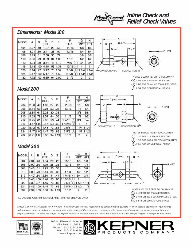
Dimensions: Model 100
Inline Check and Relief Check Valves
NOTES BELOW REFER TO COLUMN “F”
1 1 1/2 FOR 316 STAINLESS STEEL
2 1 7/8 FOR 303 & 316 STAINLESS STEEL
3 2 3/4 FOR COMMERCIAL BRASSModel 200
NOTES BELOW REFER TO COLUMN “F”
1 1 1/2 FOR 316 STAINLESS STEEL
2 1 7/8 FOR 303 & 316 STAINLESS STEEL
3 2 3/4 FOR COMMERCIAL BRASSModel 300
ALL DIMENSIONS (IN INCHES) ARE FOR REFERENCE ONLY.
NOTES BELOW REFER TO COLUMN “F”
1 1 1/2 FOR 316 STAINLESS STEEL
2 1 7/8 FOR 303 & 316 STAINLESS STEEL
3 2 3/4 FOR COMMERCIAL BRASS
CONNECTION: G CONNECTION: H
A
F HEXED
C (REF)B
CONNECTION: G CONNECTION: H
A
F HEXED
C (REF)
B
CONNECTION: G CONNECTION: H
A
F HEXED
C (REF)B B
995 N. Ellsworth AvenueVilla Park, IL 60181
Phone: 630-279-1550FAX: 630-279-9669
www.kepner.com
Consult Factory or Distributor for more help. Customer/user is solely responsible to select products suitable for their specific application requirements
and to ensure proper installation, operation and maintenance of these products. Improper selection or use of products can cause personal injury or
property damage. All sales are subject to Kepner Products Company Standard Terms and Conditions of Sale. Design subject to change without notice.

Inline Check and Relief Check Valves
Dimensions: Model 400
NOTES BELOW REFER TO COLUMN “F”
1 1 1/2 FOR 316 STAINLESS STEEL
2 1 7/8 FOR 303 & 316 STAINLESS STEEL
3 2 3/4 FOR COMMERCIAL BRASS
ALL DIMENSIONS (IN INCHES) ARE FOR REFERENCE ONLY.
Model 500
NOTES BELOW REFER TO COLUMN “F”
1 1 1/2 FOR 316 STAINLESS STEEL
2 1 7/8 FOR 303 & 316 STAINLESS STEEL
3 2 3/4 FOR COMMERCIAL BRASSModel 700
NOTES BELOW REFER TO COLUMN “F”
1 1 1/2 FOR 316 STAINLESS STEEL
2 1 7/8 FOR 303 & 316 STAINLESS STEEL
3 2 3/4 FOR COMMERCIAL BRASS
CONNECTION: G CONNECTION: H
A
F HEXED
CONNECTION: G CONNECTION: H
A
F HEXED
C (REF)B1 B2
CONNECTION: G CONNECTION: H
A
F HEXED
C (REF)B1 B2
995 N. Ellsworth AvenueVilla Park, IL 60181
Phone: 630-279-1550FAX: 630-279-9669
www.kepner.com
Consult Factory or Distributor for more help. Customer/user is solely responsible to select products suitable for their specific application requirements
and to ensure proper installation, operation and maintenance of these products. Improper selection or use of products can cause personal injury or
property damage. All sales are subject to Kepner Products Company Standard Terms and Conditions of Sale. Design subject to change without notice.

Inline Check and Relief Check Valves
Dimensions: Model 900
ALL DIMENSIONS (IN INCHES) ARE FOR REFERENCE ONLY.
Model 1100
Model 1300
NOTES BELOW REFER TO COLUMN “F”
1 1 1/2 FOR 316 STAINLESS STEEL
2 1 7/8 FOR 303 & 316 STAINLESS STEEL
3 2 3/4 FOR COMMERCIAL BRASS
NOTES BELOW REFER TO COLUMN “F”
1 1 1/2 FOR 316 STAINLESS STEEL
2 1 7/8 FOR 303 & 316 STAINLESS STEEL
3 2 3/4 FOR COMMERCIAL BRASS
NOTES BELOW REFER TO COLUMN “F”
1 1 1/2 FOR 316 STAINLESS STEEL
2 1 7/8 FOR 303 & 316 STAINLESS STEEL
3 2 3/4 FOR COMMERCIAL BRASS
CONNECTION: G CONNECTION: H
A
F HEXED
C (REF)
CONNECTION: G CONNECTION: H
A
F HEXED
C (REF)B
CONNECTION: G CONNECTION: H
A
F HEXED
C (REF)B B
995 N. Ellsworth AvenueVilla Park, IL 60181
Phone: 630-279-1550FAX: 630-279-9669
www.kepner.com
Consult Factory or Distributor for more help. Customer/user is solely responsible to select products suitable for their specific application requirements
and to ensure proper installation, operation and maintenance of these products. Improper selection or use of products can cause personal injury or
property damage. All sales are subject to Kepner Products Company Standard Terms and Conditions of Sale. Design subject to change without notice.

Inline Check and Relief Check Valves
Dimensions: Model 1500
ALL DIMENSIONS (IN INCHES) ARE FOR REFERENCE ONLY.
Model 1700
Model 1900
NOTES BELOW REFER TO COLUMN “F”
1 1 1/2 FOR 316 STAINLESS STEEL
2 1 7/8 FOR 303 & 316 STAINLESS STEEL
3 2 3/4 FOR COMMERCIAL BRASS
NOTES BELOW REFER TO COLUMN “F”
1 1 1/2 FOR 316 STAINLESS STEEL
2 1 7/8 FOR 303 & 316 STAINLESS STEEL
3 2 3/4 FOR COMMERCIAL BRASS
NOTES BELOW REFER TO COLUMN “F”
1 1 1/2 FOR 316 STAINLESS STEEL
2 1 7/8 FOR 303 & 316 STAINLESS STEEL
3 2 3/4 FOR COMMERCIAL BRASS
CONNECTION: G CONNECTION: H
A
F HEXED
C (REF)
B
CONNECTION: G CONNECTION: H
A
F HEXED
C (REF)B
CONNECTION: G CONNECTION: H
A
F HEXED
995 N. Ellsworth AvenueVilla Park, IL 60181
Phone: 630-279-1550FAX: 630-279-9669
www.kepner.com
Consult Factory or Distributor for more help. Customer/user is solely responsible to select products suitable for their specific application requirements
and to ensure proper installation, operation and maintenance of these products. Improper selection or use of products can cause personal injury or
property damage. All sales are subject to Kepner Products Company Standard Terms and Conditions of Sale. Design subject to change without notice.

Adjustable InlineRelief Valves
These adjustable, spring-loaded poppet valves are used to limit system pressure. Excess pres-sure unseats the poppet, allowing flow with minimal increase in system pressure. As fluid isreleased the system pressure decreases until the spring force re-seats the poppet. Kepner'sFlexible Seal Seat� ensures bubble-tight shutoff of liquid or gas.
The relief pressure can be set using a tamperproof internal adjustment screw. Standard and spe-cialty valves handle a wide variety of applications requiring fast acting relief performance andtamperproof pressure adjustment.
Features and Benefits:
● Flexible Seal Seat� for zero leak (bubble-tight) seal ● Outer O-Ring provides non-pressurized threads● Both O-Ring seals positively secured● Wide relief adjustment range 50 to 2000 PSI (3.45 to 138 bar)● Tamperproof Nylok® adjustment to set relief pressure/prevent slippage● Poppet stop inside valve body prevents spring from bottoming out
Valve Specifications:
● End Connections: Pipe (MPT, FPT; 10 combinations)Inlet (MPT or FPT); Outlet (FPT); Side Outlet (1/4 inch FPT)
● Port Sizes: 1/4 inch, 3/8 inch, 1/2 inch ● Body Materials: Steel, 303 Stainless Steel● O-Ring Seals: Teflon®, other materials available ● Temperature: -300°F to 450°F (-184°C to 232°C), O-Ring dependent● Crack Pressure Ranges: Adjustable 50 to 2000 PSI (3.5 to 138 bar)
3 Spring Ranges: 50 to 400 PSI (3.5 to 28 bar), 300 to 1000 PSI (21 to 69 bar), 900 to 2000 PSI (62 to 138 bar); factory preset pressure available
● Operating Pressure: to 3000 PSI (207 bar)● Flow: to 10 GPM (38 LPM)
995 N. Ellsworth AvenueVilla Park, IL 60181
Phone: 630-279-1550FAX: 630-279-9669
www.kepner.com
Consult Factory or Distributor for more help. Customer/user is solely responsible to select products suitable for their specific application requirements
and to ensure proper installation, operation and maintenance of these products. Improper selection or use of products can cause personal injury or
property damage. All sales are subject to Kepner Products Company Standard Terms and Conditions of Sale. Design subject to change without notice.

Flow Charts:
Adjustable InlineRelief Valves
Test Fluid: MIL-H-5606A Hydraulic Oil Test Temp: 100o F (Viscosity 77.5 SUS) *TYP. - Covers Models 2300 thru 2309
Curves indicate Pressure Drop vs Flow RateInitialSetting MODEL *2300-400
FLOW RATE - GPM
RELI
EF
LIM
ITIN
GPR
ESSU
RE -
PS
I
InitialSetting MODEL *2300-1000
RELI
EF
LIM
ITIN
G P
RESSU
RE -
PS
I
FLOW RATE - GPM
InitialSetting MODEL *2300-2000
RELI
EF
LIM
ITIN
G P
RESSU
RE -
PS
I
FLOW RATE - GPM
995 N. Ellsworth AvenueVilla Park, IL 60181
Phone: 630-279-1550FAX: 630-279-9669
www.kepner.com
Consult Factory or Distributor for more help.
Customer/user is solely responsible to select
products suitable for their specific applica-
tion requirements and to ensure proper
installation, operation and maintenance of
these products. Improper selection or use
of products can cause personal injury or
property damage. All sales are subject to
Kepner Products Company Standard Terms
and Conditions of Sale. Design subject to
change without notice.

O-RING SEALS: TEFLON®
FACTORYPRESETCRACK
PRESSUREOPTIONAL
PORT SIZESINLET OUTLET SIDE OUTLET
00 1/2 MPT 1/2 FPT NONE01 1/2 FPT 1/2 FPT NONE02 3/8 MPT 3/8 FPT NONE03 3/8 FPT 3/8 FPT NONE04 1/4 MPT 1/4 FPT 1/4 FPT05 1/4 FPT 1/4 FPT 1/4 FPT06 1/2 MPT 1/4 FPT 1/4 FPT07 1/2 FPT 1/4 FPT 1/4 FPT08 3/8 MPT 1/4 FPT 1/4 FPT09 3/8 FPT 1/4 FPT 1/4 FPT
CONSTRUCTION MATERIALSC = STEEL D = 303 STAINLESS STEEL i
CRACK PRESSURE RANGES400 = 50 - 400 PSI CRACK
. 1000 = 300 - 1000 PSI CRACK 2000 = 900 - 2000 PSI CRACK
PART NUMBER EXAMPLE23 05 C - 1000 (750PSI)
BASENO.
Dimension Diagram and Part Numbers:
Adjustable InlineRelief Valves
Model:23002302230423062308
Model:23012303230523072309
CONNECTION: FCONNECTION: G
A
HD
SIDE PORT
CONNECTION: ECONNECTION: G
A
1 1/8”HEX
.47
DC (REF)B
1.19
1 1/8”HEX1.19
.47
All dimensions (in inches) for reference only.
SIDEPORT
H
995 N. Ellsworth AvenueVilla Park, IL 60181
Phone: 630-279-1550FAX: 630-279-9669
www.kepner.com
Consult Factory or Distributor for more help. Customer/user is solely responsible to select products suitable for their specific application requirements
and to ensure proper installation, operation and maintenance of these products. Improper selection or use of products can cause personal injury or
property damage. All sales are subject to Kepner Products Company Standard Terms and Conditions of Sale. Design subject to change without notice.


High Pressure Checkand Relief/Check Valves
These inline valves allow free flow in only one direction, prevent backflow, and meet the indus-try's need for higher operating pressures. They also are used for relief and by-pass functions.Kepner's Flexible Seal Seat� combines metal-to-metal contact with a resilient seal seat ensuringbubble-tight shutoff of liquid or gas. This is an ideal choice for applications that require positiveleak-tight sealing and long service life at pressures to 6000 PSI. Standard and specialty valveshandle a wide variety of applications.
Features and Benefits:
● Flexible Seal Seat� for zero leak (bubble-tight) sealing to 6000 PSI● O-Ring seal positively secured● Non-pressurized threads● Poppet stop inside valve body prevents spring from bottoming out● Generous flow passages allow full flow with minimal pressure drop
Valve Specifications:
● End Connections: Pipe or Tube (NPT, JIC; 12 combinations)● Port Sizes: 1/8 inch to 1 inch (3.2 mm to 25 mm)● Body Materials: Steel, 303 Stainless Steel● O-Ring Seals: Teflon®, other materials available ● Temperature: -300°F to 450°F (-184°C to 232°C), O-Ring dependent● Relief/Check Valve Crack Pressures: 5 PSI (.35 bar), 10 PSI (0.7 bar), 25 PSI
(1.7 bar), 50 PSI (3.5 bar) and 65 PSI (4.5 bar), others available● Operating Pressure: to 6000 PSI (414 bar)● Flow: to 25 GPM (95 LPM)
995 N. Ellsworth AvenueVilla Park, IL 60181
Phone: 630-279-1550FAX: 630-279-9669
www.kepner.com
Consult Factory or Distributor for more help. Customer/user is solely responsible to select products suitable for their specific application requirements
and to ensure proper installation, operation and maintenance of these products. Improper selection or use of products can cause personal injury or
property damage. All sales are subject to Kepner Products Company Standard Terms and Conditions of Sale. Design subject to change without notice.

High Pressure Checkand Relief/Check Valves
Flow Chart and Part Number: Fixed settings 1/8” to 1” sizes.
FLOW - GALLONS PER MINUTE
Test Fluid: Water Test Temp: 50oF
PR
ES
SU
RE
DR
OP
- P
SI
59 IJIC - IJIC 47 JIC - MPT
57 JIC - IJIC 45 MPT - JIC
55 IJIC - JIC 44 FPT - FPT
53 JIC - JIC 43 MPT- MPT
51 JIC - FPT 42 FPT - MPT
49 FPT - JIC 41 MPT - FPT
IJIC IJIC JIC MPTTUBE TO TUBE TUBE TO PIPE
JIC IJIC MPT JICTUBE TO TUBE PIPE TO TUBE
IJIC JIC FPT FPTTUBE TO TUBE PIPE TO PIPE
JIC JIC MPT MPTTUBE TO TUBE PIPE TO PIPE
JIC FPT FPT MPTTUBE TO PIPE PIPE TO PIPE
FPT JIC MPT FTPPIPE TO TUBE PIPE TO PIPE
PORT CONFIGURATIONS PART NUMBER EXAMPLE
44 06 C - 3 - 25
PORT SIZES04 = 1/8 PIPE - 1/4 TUBE 10 = 1/2 PIPE - 5/8 TUBE06 = 1/4 PIPE - 3/8 TUBE 12 = 3/4 PIPE - 3/4 TUBE 08 = 3/8 PIPE - 1/2 TUBE 16 = 1” PIPE - 1” TUBE
CONSTRUCTION MATERIALSC = STEEL D = 303 STAINLESS STEEL
O-RING SEALS
3 = TEFLON®
CRACK PRESSURE
5 = 5 PSI CRACK 10 = 10 PSI CRACK 25 = 25 PSI CRACK 50 = 50 PSI CRACK 65 = 65 PSI CRACK
OTHERSAVAILABLE
995 N. Ellsworth AvenueVilla Park, IL 60181
Phone: 630-279-1550FAX: 630-279-9669
www.kepner.com
Consult Factory or Distributor for more help.
Customer/user is solely responsible to select products
suitable for their specific application requirements and to
ensure proper installation, operation and maintenance of
these products. Improper selection or use of products
can cause personal injury or property damage. All sales
are subject to Kepner Products Company Standard Terms
and Conditions of Sale. Design subject to change without
notice.

Model 4400
High Pressure Checkand Relief/Check Valves
Dimensions: Fixed settings 1/8” to 1” sizesA
F HEXED
C (REF)B
CONNECTION: G CONNECTION: H
NOTES REFER TO COLUMN “F”1 1 7/8 FOR 303 STAINLESS STEEL
Model 4100
A
F HEXED
C (REF)
B
CONNECTION: G CONNECTION: H
NOTES REFER TO COLUMN “F”1 1 7/8 FOR 303 STAINLESS STEEL
Model 4200
Model 4300A
F HEXED
C (REF) B
CONNECTION: G CONNECTION: H
NOTES REFER TO COLUMN “F”1 1 7/8 FOR 303 STAINLESS STEEL
B
A
F HEXED
CONNECTION: G CONNECTION: H
NOTES REFER TO COLUMN “F”1 1 7/8 FOR 303 STAINLESS STEEL
ALL DIMENSIONS (IN INCHES) ARE FOR REFERENCE ONLY.
995 N. Ellsworth AvenueVilla Park, IL 60181
Phone: 630-279-1550FAX: 630-279-9669
www.kepner.com

High Pressure Checkand Relief/Check Valves
Dimensions: Fixed settings 1/8” to 1” sizesA
F HEXED
C (REF)B1
CONNECTION: G CONNECTION: H
NOTES REFER TO COLUMN “F”1 1 7/8 FOR 303 STAINLESS STEEL
Model 4500
F HEXED
C (REF)B1
CONNECTION: G CONNECTION: H
NOTES REFER TO COLUMN “F”1 1 7/8 FOR 303 STAINLESS STEEL
Model 4700
Model 4900
Model 5100
A
F HEXED
C (REF)
B
CONNECTION: G CONNECTION: H
NOTES REFER TO COLUMN “F”1 1 7/8 FOR 303 STAINLESS STEEL
A
F HEXED
CONNECTION: G CONNECTION: H
NOTES REFER TO COLUMN “F”1 1 7/8 FOR 303 STAINLESS STEELALL DIMENSIONS (IN INCHES) ARE FOR REFERENCE ONLY.
B2
B2
C (REF)B
A
995 N. Ellsworth AvenueVilla Park, IL 60181
Phone: 630-279-1550FAX: 630-279-9669
www.kepner.com

High Pressure Checkand Relief/Check Valves
Dimensions: Fixed settings 1/4” to 1” sizes
CONNECTION: G CONNECTION: H
Model 5300
A
F HEXED
C (REF)
B
CONNECTION: G CONNECTION: H
NOTES REFER TO COLUMN “F”1 1 7/8 FOR 303 STAINLESS STEEL
Model 5700
Model 5500
A
F HEXED
C (REF)
CONNECTION: G CONNECTION: H
NOTES REFER TO COLUMN “F”1 1 7/8 FOR 303 STAINLESS STEEL
B
A
F HEXED
CONNECTION: G CONNECTION: H
NOTES REFER TO COLUMN “F”1 1 7/8 FOR 303 STAINLESS STEEL
ALL DIMENSIONS (IN INCHES) ARE FOR REFERENCE ONLY.
A
F HEXED
C (REF)B
NOTES REFER TO COLUMN “F”1 1 7/8 FOR 303 STAINLESS STEEL
B
Model 5900
995 N. Ellsworth AvenueVilla Park, IL 60181
Phone: 630-279-1550FAX: 630-279-9669
www.kepner.com


Inline Ball Check Valves
Ball check valves allow free flow in only one direction, prevent backflow, and are for applica-tions where poppet style valves may not be suitable (such as media with contamination, viscousfluids, etc.). They are trouble free with large flow paths. The need for closely mating surfacesand sliding parts has been eliminated by the conical tension spring and seal seat design.Kepner's Flexible Seal Seat� design combines metal-to-metal contact with a resilient seal seatto ensure bubble-tight shutoff of liquid or gas, and long service life.
Features and Benefits:
● Flexible Seal Seat� for zero leak (bubble-tight) seal at low and high pressures● O-Ring seal positively secured● Stainless steel ball design; no sliding parts ● Exclusive conical tension spring design allows for greater flow ● Handles contamination, viscous liquids and slurries
Valve Specifications:
● End Connections/Sizes: 1/8 inch to 3/4 inch FPT ● Body Materials: Brass, 303 Stainless Steel● O-Ring Seals: Buna-N, Teflon®, Viton®, other materials available ● Temperature: -300°F to 450°F (-184°C to 232°C), O-Ring dependent● Crack Pressure: 1 to 3 PSI (.07 bar to 0.21 bar)● Operating Pressure: to 3000 PSI (207 bar)● Flow: to 25 GPM (95 LPM)
995 N. Ellsworth AvenueVilla Park, IL 60181
Phone: 630-279-1550FAX: 630-279-9669
www.kepner.com
Consult Factory or Distributor for more help. Customer/user is solely responsible to select products suitable for their specific application requirements
and to ensure proper installation, operation and maintenance of these products. Improper selection or use of products can cause personal injury or
property damage. All sales are subject to Kepner Products Company Standard Terms and Conditions of Sale. Design subject to change without notice.

Inline Ball Check Valves
CONNECTION: C CONNECTION: C
A B HEXD
ALL DIMENSIONS (IN INCHES) ARE FOR REFERENCE ONLY.
Dimension Diagram, Part Numbers and Flow Chart:
PART NUMBER EXAMPLE4 56 B - 1 BASE MODEL NUMBER
PORT SIZES54 = 1/8 FPT 60 = 1/2 FPT56 = 1/4 FPT 62 = 3/4 FPT58 = 3/8 FPT
CONSTRUCTION MATERIALSB = BRASS D = 303 STAINLESS STEEL i
O-RING SEALS1 = BUNA-N
3 = TEFLON®
18 = VITON®
CRACK PRESSURE: 1-3 PSI CRACK
MODEL SIZE
FEMALEPIPE THREAD
454 1/8”
456 1/4”
458 3/8”
460 1/2”
462 3/4”
FLOW - GALLONS PER MINUTE
Curves indicate Pressure Drop vs. Flow Rate
PR
ES
SU
RE
DR
OP
- P
SI
Test Fluid: MIL-H-5606A Hydraulic Oil Test Temp: 75o F
995 N. Ellsworth AvenueVilla Park, IL 60181
Phone: 630-279-1550FAX: 630-279-9669
www.kepner.com
Consult Factory or Distributor for more help. Customer/user is solely responsible to select products suitable for their specific application requirements
and to ensure proper installation, operation and maintenance of these products. Improper selection or use of products can cause personal injury or
property damage. All sales are subject to Kepner Products Company Standard Terms and Conditions of Sale. Design subject to change without notice.

Inline Shuttle Valves
The shuttle valve permits flow from either of two inlet ports to a common outlet. A free floatingmetal ball shuttles according to the relative pressure at the two inlets. The higher pressure inletflows through the valve and moves the ball to close the opposite inlet. Kepner's Flexible SealSeat� combines metal-to-metal contact with a resilient seal seat to ensure bubble-tight shutoffof liquid or gas, and long service life. Shuttle valves can also flow in the reverse direction, andrelieve system pressure when input is removed. Standard and specialty valves handle a widevariety of control applications, including use in logic circuits, for pilot signal input and venting,dual input pilot control, and for switching to alternate or standby systems.
Features and Benefits:
● Flexible Seal Seat� for zero leak (bubble-tight) seal at closed port● Non-biased free floating shuttle ball with short travel path● Minimal pressure differential shifting● O-Ring seal positively secured● Unobstructed flow paths allow full flow and minimal pressure drop
Valve Specifications:
● End Connections/Sizes: 1/8 inch to 3/4 inch FPT● Body Materials: Brass, Steel, 303 Stainless Steel● O-Ring Seals: Buna-N, Teflon®, Viton®, other materials available● Temperature: -300°F to 450°F (-184°C to 232°C), O-Ring dependent● Operating Pressure: to 3000 PSI (207 bar)● Flow: to 60 GPM (227 LPM)
995 N. Ellsworth AvenueVilla Park, IL 60181
Phone: 630-279-1550FAX: 630-279-9669
www.kepner.com
Consult Factory or Distributor for more help. Customer/user is solely responsible to select products suitable for their specific application requirements
and to ensure proper installation, operation and maintenance of these products. Improper selection or use of products can cause personal injury or
property damage. All sales are subject to Kepner Products Company Standard Terms and Conditions of Sale. Design subject to change without notice.

Shuttle Valves
995 N. Ellsworth AvenueVilla Park, IL 60181
Phone: 630-279-1550FAX: 630-279-9669
www.kepner.com
Dimension Diagram, Part Numbers and Flow Chart:
BASE MODEL NUMBER
PORT SIZES54 = 1/8 FPT 60 = 1/2 FPT56 = 1/4 FPT 62 = 3/4 FPT58 = 3/8 FPT
CONSTRUCTION MATERIALSB = BRASS C = STEEL D = 303 STAINLESS STEEL i
O-RING SEALS1 = BUNA-N
3 = TEFLON®
9 = NEOPRENE
18 = VITON®
25 = ETHYLENEPROPYLENE
CRACK PRESSURE: 1-3 PSI CRACK
MODEL SIZE
NPTF FEMALEPIPE THREAD
2454 1/8”
2456 1/4”
2458 3/8”
2460 1/2”
2462 3/4”
INLETCONNECTION
H NPTF
INLETCONNECTIONH NPTF
F DIA. THRU(2 PLACES)
A
D
2EE OUTLET
CONNECTIONH NPTF
C
B
I
GHEX
ALL DIMENSIONS (IN INCHES) ARE FOR REFERENCE ONLY.
PART NUMBER EXAMPLE24 56 C - 1
PR
ES
SU
RE
DR
OP
- P
SI
FLOW - GALLONS PER MINUTETest Fluid: MIL-H-5606A Hydraulic Oil Test Temp: 75o F
Curves indicate Pressure Drop vs. Flow Rate
2454
2462
246024582456
Consult Factory or Distributor for more help. Customer/user is solely responsible to select products suitable for their specific application requirements
and to ensure proper installation, operation and maintenance of these products. Improper selection or use of products can cause personal injury or
property damage. All sales are subject to Kepner Products Company Standard Terms and Conditions of Sale. Design subject to change without notice.

Fixed Orifice Flow Control Restrictor Valves
Fixed Orifice Flow Controls provide free flow in one direction andrestricted (metered) flow in the reverse direction. They are standardKep-O-seal® or Kepsel® check valves, equipped with a calibratedorifice drilled through the valve poppet nose. Kepner's bubble-tightFlexible Seal Seat� ensures that the reverse flow is precisely con-trolled by confining it to the calibrated orifice. Such valves are oftenused in charging lines for cylinders, containers, or accumulatorswhere it is desired to rapidly charge and then bleed back the chargedfluid at a pre-determined rate. These valves handle many otherapplications.
Features and Benefits:
● Generous flow passages allow full free-flow with minimal pressure drop ● Metered reverse flow ● Tamperproof internal orifice ● Rugged and dependable
Valve Specifications:
● Fixed Orifice Flow Control Restrictor sizes and specifications are the same as those shown for the standard Kep-O-seal® or Kepsel® check valves, except for cracking pressure and internal leakage which obviously do not apply.
● The valve orifice is drilled to customer's specifications. Test data and flow calibration based on Air or MIL-H-5606 Hydraulic Oil can be provided.
995 N. Ellsworth AvenueVilla Park, IL 60181
Phone: 630-279-1550FAX: 630-279-9669
www.kepner.com
Consult Factory or Distributor for more help. Customer/user is solely responsible to select products suitable for their specific application requirements
and to ensure proper installation, operation and maintenance of these products. Improper selection or use of products can cause personal injury or
property damage. All sales are subject to Kepner Products Company Standard Terms and Conditions of Sale. Design subject to change without notice.

Fixed Orifice Flow ControlRestrictor Valves
Part Numbers: Kep-O-seal� Inline and Kepsel� Cartridge Type Insert Fixed Orifice Flow Control Restrictor Valves*
1/8” TO 3” SIZES PART NUMBER EXAMPLE
4 06 C - 1 - 25 (.062)
See Kep-O-seal� Inline Check and Relief Check Valves and add the Orifice Size to the Part Number as shown in the Part Number Example.
ORIFICE SIZE (Thousandths of an inch)
1/16” to 2” NOMINAL SIZES PART NUMBER EXAMPLE
22 06 C - 1 - 25 (.062)
See Kepsel� Cartridge Check and Relief Check Valves, and add the Orifice Size to the Part Number as shown in the Part Number Example.
ORIFICE SIZE (Thousandths of an inch)
*NOTE: All poppet designs can be converted to Flow Control Restrictor Valves by adding an Orifice and Designator as shown in the Part Number Examples above.
995 N. Ellsworth AvenueVilla Park, IL 60181
Phone: 630-279-1550FAX: 630-279-9669
www.kepner.com
Consult Factory or Distributor for more help. Customer/user is solely responsible to select products suitable for their specific application requirements
and to ensure proper installation, operation and maintenance of these products. Improper selection or use of products can cause personal injury or
property damage. All sales are subject to Kepner Products Company Standard Terms and Conditions of Sale. Design subject to change without notice.

Split Flange Check and Relief/Check Valves
The flanged, spring-operated, poppet valves allow free flowin only one direction and prevent backflow. They are alsoused for relief and by-pass functions. The valves can bedirect mounted to pumps, motors, and other such applications where threaded end connec-tions are impractical or inconvenient. Kepner's Flexible Seal Seat� combines metal-to-metalcontact with a resilient seal seat ensuring dependable bubble-tight shutoff of liquid or gas, aswell as surge protection and long service life. Standard and specialty valve designs handle awide variety of applications.
Features and Benefits:
● Flexible Seal Seat� for zero leak (bubble-tight) seal at low and high pressures● SAE 4-bolt, Code 61 mounting; easy installation and maintenance● O-Ring seal positively secured● Poppet stop inside valve body prevents spring from bottoming out● Generous flow passages allow full flow with minimal pressure drop
Valve Specifications:
● Nominal SAE Flange Sizes: 3/4 inch to 2 inch (19 mm to 51mm)● Body Materials: Steel ● O-Ring Seals: Buna-N, Neoprene, Viton®, EP, other materials available ● Temperature: -300°F to 450°F (-184°C to 232°C), O-Ring dependent● Check Valve Crack Pressure: 1 to 2 PSI (.07 bar to 0.14 bar)● Relief/Check Valve Crack Pressures: 5 PSI (.35 bar), 10 PSI (0.7 bar),
25 PSI (1.7 bar), 50 PSI (3.5 bar), 65 PSI (4.5 bar), others available● Operating Pressure: to 3000 PSI (207 bar)● Flow: to 120 GPM (454 LPM)
995 N. Ellsworth AvenueVilla Park, IL 60181
Phone: 630-279-1550FAX: 630-279-9669
www.kepner.com
Consult Factory or Distributor for more help. Customer/user is solely responsible to select products suitable for their specific application requirements
and to ensure proper installation, operation and maintenance of these products. Improper selection or use of products can cause personal injury or
property damage. All sales are subject to Kepner Products Company Standard Terms and Conditions of Sale. Design subject to change without notice.

Split Flange Check Valves
O-RING GROOVEBOTH ENDS
E D
ALL DIMENSIONS (IN INCHES) ARE FOR REFERENCE ONLY.
Dimension Diagram and Part Numbers:
PART NUMBER EXAMPLE26 16 C - 1 - (25)BASE MODEL NUMBER
NOMINAL SIZES12 = 3/4” 24 = 1 1/2” 16 = 1” 32 = 2”20 = 1 1/4”
CONSTRUCTION MATERIALSC = STEELi
O-RING SEALS1 = BUNA-N 9 = NEOPRENE 18 = VITON®
25 = ETHYLENE PROPYLENE OTHERS AVAILABLE
STANDARD CRACK PRESSURE1-3 PSI CRACK
� AOUTLET PORT
� G(4 PLACES)
� AINLET PORT
C
F B
RELIEF CRACK PRESSURES
5=5 PSI CRACK10=10 PSI CRACK25=25 PSI CRACK50=50 PSI CRACK65=65 PSI CRACK
995 N. Ellsworth AvenueVilla Park, IL 60181
Phone: 630-279-1550FAX: 630-279-9669
www.kepner.com
Consult Factory or Distributor for more help. Customer/user is solely responsible to select products suitable for their specific application requirements
and to ensure proper installation, operation and maintenance of these products. Improper selection or use of products can cause personal injury or
property damage. All sales are subject to Kepner Products Company Standard Terms and Conditions of Sale. Design subject to change without notice.

Split Flange Check Valves
Flow Charts:
FLOW - GALLONS PER MINUTETest Fluid: MIL-H-5606A HYDRAULIC OIL Test Temp: 50oF
PR
ES
SU
RE
DR
OP
- P
SI
MODELSIZE SAE FLANGE
2612 3/4”
2616 1”
2620 1-1/4”
2624 1-1/2”
2632 2”
PR
ES
SU
RE
DR
OP
- P
SI
FLOW - GALLONS PER MINUTETest Fluid: MIL-H-5606A HYDRAULIC OIL Test Temp: 70o F
EXAMPLE WITH VARIOUS RELIEF SETTINGS
Curves indicate Pressure Drop vs Flow Rate
995 N. Ellsworth AvenueVilla Park, IL 60181
Phone: 630-279-1550FAX: 630-279-9669
www.kepner.com
Consult Factory or Distributor for more help. Customer/user
is solely responsible to select products suitable for their spe-
cific application requirements and to ensure proper installa-
tion, operation and maintenance of these products. Improper
selection or use of products can cause personal injury or
property damage. All sales are subject to Kepner Products
Company Standard Terms and Conditions of Sale. Design sub-
ject to change without notice.


Cartridge TypeInsert Check Valves
995 N. Ellsworth AvenueVilla Park, IL 60181
Phone: 630-279-1550FAX: 630-279-9669
www.kepner.com
Kepsel® cartridge valves are designed for simple installation (no expensive machining for cavity)and offer the same outstanding performance as their counterpart Kep-O-seal® inline valves.These spring-operated poppet valves, with optional relief settings, allow free flow in only onedirection and prevent backflow. They also are used for relief and by-pass functions. Kepner'sFlexible Seal Seat� ensures bubble-tight shutoff of liquid or gas, and long service life. Standardand specialty valve designs handle a wide variety of applications, and are ideal for use in sub-plate and manifold assemblies, pump inlet/outlet, and cylinder blocks.
Features and Benefits:
● Flexible Seal Seat� for zero leak (bubble-tight) seal at low and high pressures● No threaded connections (avoid potential leakage)● O-Ring seal positively secured ● Poppet stop inside valve body prevents spring from bottoming out● Generous flow passages allow full flow with minimal pressure drop● Compact, easy installation - Accessory Kepner Holding Device Kits available
Valve Specifications:
● Nominal Sizes: 1/16 inch to 2 inch (1.6 mm to 51 mm; 9 Sizes)● Body Materials: Brass, Steel, 303 or 316 Stainless Steel ● O-Ring Seals: Buna-N, Neoprene, Viton®, EP, other materials available● Temperature: -300°F to 450°F (-184°C to 232°C), O-Ring dependent● Check Crack Pressure: 1 to 2 PSI (.07 bar to .14 bar)● Relief/Check Crack Pressures: 5 PSI (.35 bar), 10 PSI (0.7 bar), 25 PSI (1.7 bar),
50 PSI (3.5 bar) and 65 PSI (4.5 bar), others available● Operating Pressure: to 3000 PSI (207 bar)● Flow: to 200 GPM (757 LPM)
Consult Factory or Distributor for more help. Customer/user is solely responsible to select products suitable for their specific application requirements
and to ensure proper installation, operation and maintenance of these products. Improper selection or use of products can cause personal injury or
property damage. All sales are subject to Kepner Products Company Standard Terms and Conditions of Sale. Design subject to change without notice.

995 N. Ellsworth AvenueVilla Park, IL 60181
Phone: 630-279-1550FAX: 630-279-9669
www.kepner.com
Cartridge TypeInsert Check Valves
Dimension Diagrams:
MODEL 2201AND 2203
DIRECTION OF FREE FLOW
H OUTLET DIA.H INLET DIA.
MODELS2206 TO 2232
� CREF.
� CREF.
� A
� B � A
G
DG
D
J
J
H OUTLET DIA.
H INLET DIA.
NOTES:1) ALL DIMENSIONS (IN INCHES ARE FOR REFERENCE ONLY.2) VALVE MUST BE HELD END - FOR - END IN USE.
F
E
Consult Factory or Distributor for more help. Customer/user is solely responsible to select products suitable for their specific application requirements
and to ensure proper installation, operation and maintenance of these products. Improper selection or use of products can cause personal injury or
property damage. All sales are subject to Kepner Products Company Standard Terms and Conditions of Sale. Design subject to change without notice.

995 N. Ellsworth AvenueVilla Park, IL 60181
Phone: 630-279-1550FAX: 630-279-9669
www.kepner.com
Cartridge TypeInsert Check Valves
Part Number and Flow Charts: PART NUMBER EXAMPLE22 06 C - 1
BASE MODEL NUMBER
NOMINAL SIZES
01 = 1/16” 08 = 3/8” 16 = 1” 03 = 1/8” 10 = 1/2” 24 = 1 1/2” 06 = 1/4” 12 = 3/4” 32 = 2”
CONSTRUCTION MATERIALS
B = BRASS D = 303 STAINLESS STEELC = STEEL i F = 316 STAINLESS STEEL
O-RING SEALS1 = BUNA-N 9 = NEOPRENE 18 = VITON® 25 = ETHYLENE PROPYLENE OTHERS AVAILABLE
FLOW GALLONS PER MINUTETest Fluid: MIL-H-5606A Hydraulic Oil
Test Temp: 75� F
FLOW GALLONS PER MINUTETest Fluid: MIL-H-5606A Hydraulic Oil Test Temp: 75� F
FLOW GALLONS PER MINUTETest Fluid: MIL-H-5606A Hydraulic Oil Test Temp: 75� F
PR
ES
SU
RE
DR
OP
- P
SI
PR
ES
SU
RE
DR
OP
- P
SI
PR
ES
SU
RE
DR
OP
- P
SI
Consult Factory or Distributor for more help.
Customer/user is solely responsible to select
products suitable for their specific application
requirements and to ensure proper installation,
operation and maintenance of these products.
Improper selection or use of products can
cause personal injury or property damage. All
sales are subject to Kepner Products Company
Standard Terms and Conditions of Sale. Design
subject to change without notice.


Cartridge Type InsertAdjustable Relief Valves
995 N. Ellsworth AvenueVilla Park, IL 60181
Phone: 630-279-1550FAX: 630-279-9669
www.kepner.com
The Kepsel® cartridge has the same internal features as its counterpart Kep-O-seal® adjustableinline relief valve.These adjustable, spring-loaded poppet valves are used to limit system pressure.Excess pressure unseats the poppet, allowing flow with minimal increase in system pressure. Asfluid is released the system pressure decreases until the spring force re-seats the poppet. Kepner'sFlexible Seal Seat� ensures bubble-tight shutoff of liquid or gas. The relief pressure can be setusing a tamperproof internal adjustment screw. Standard and specialty valves handle a wide vari-ety of relief applications, and are ideal for use in a manifold, sub-plate, or cylinder head.
Features and Benefits:
● Flexible Seal Seat� for zero leak (bubble-tight) seal ● No threaded connections (avoid potential leakage)● O-Ring seals positively secured● Wide relief adjustment range 50 to 2000 PSI (3.45 to 138 bar)● Tamperproof Nylok® adjustment set relief pressure/prevent slippage● Poppet stop inside valve body prevents spring from bottoming out● Compact, easy installation - Accessory Kepner Holding Device Kits available
Valve Specifications:
● Size: 1 inch cavity (25.4 mm) ● Body Materials: Steel, 303 Stainless Steel● O-Ring Seals: Teflon®, other materials available ● Temperature: -300°F to 450°F (-184°C to 232°C), O-Ring dependent● Crack Pressure Ranges: Adjustable 50 to 2000 PSI (3.5 to 138 bar)
3 Spring Ranges: 50 to 400 PSI (3.5 to 28 bar), 300 to 1000 PSI (21 to 69 bar), 900 to 2000 PSI (62 to 138 bar); factory preset pressure available
● Operating Pressure: to 3000 PSI (207 bar)● Flow: to 10 GPM (38 LPM)
Consult Factory or Distributor for more help. Customer/user is solely responsible to select products suitable for their specific application requirements
and to ensure proper installation, operation and maintenance of these products. Improper selection or use of products can cause personal injury or
property damage. All sales are subject to Kepner Products Company Standard Terms and Conditions of Sale. Design subject to change without notice.

995 N. Ellsworth AvenueVilla Park, IL 60181
Phone: 630-279-1550FAX: 630-279-9669
www.kepner.com
Dimension Diagram and Part Number:
2.151/ 2.161
OUTLET PORT: 3/8 HOLLOW HEX..11INLET PORT: 19/64 DIA.
� .81 REF.
.11.09
� .886 /.881� .999 /.994
NOTES:1. CRACK PRESSURE ADJUSTABLE2. VALVE MUST BE HELD END FOR END IN USE3. ALL DIMENSIONS (IN INCHES) ARE FOR REFERENCE ONLY
PART NUMBER EXAMPLE1354 C - 1000
BASE MODEL NUMBER
CONSTRUCTION MATERIALSC = STEEL D = 303 STAINLESS STEEL i
O-RING SEALSEXTERNAL SEAL: STANDARD SIZE NUMBER: 020
INTERNAL SEAL: TEFLON®
Elastomeric seals available on request.
ADJUSTMENTBy means of a standard 3/8” hex wrenchinserted through the inline outlet port.
MODEL SUFFIX ADJUSTMENT RANGE-400 50 TO 400 PSI-1000 300 TO 1000 PSI-2000 900 TO 2000 PSI
ADJUSTMENTRANGE
Cartridge Type InsertAdjustable Relief Valves
Consult Factory or Distributor for more help. Customer/user is solely responsible to select products suitable for their specific application requirements
and to ensure proper installation, operation and maintenance of these products. Improper selection or use of products can cause personal injury or
property damage. All sales are subject to Kepner Products Company Standard Terms and Conditions of Sale. Design subject to change without notice.

Cartridge Type InsertShuttle Valves
995 N. Ellsworth AvenueVilla Park, IL 60181
Phone: 630-279-1550FAX: 630-279-9669
www.kepner.com
The cartridge shuttle valve permits flow from either of two inlet ports to a common outlet.Similar to the Kep-O-seal® inline version, a free floating metal ball shuttles according to the rel-ative pressure at the two inlets. The higher pressure inlet flows through the valve and movesthe ball to close the opposite inlet. Kepner's Flexible Seal Seat� ensures bubble-tight shutoffof liquid or gas, and long service life. Shuttle valves can also flow in the reverse direction, andrelieve system pressure when input is removed. Standard and specialty valves handle a widevariety of applications, and are ideal for use in manifolds, subplates, or cylinder heads.
Features and Benefits:
● Flexible Seal Seat� for zero leak (bubble-tight) seal at closed port● No threaded connections (avoid potential leakage)● Non-biased free floating shuttle ball with short travel path● Minimal pressure differential shifting● O-Ring positively secured● Compact, easy installation - Accessory Kepner Holding Device Kits available
Valve Specifications:
● Sizes: 1/16 inch to 3/4 inch Nominal sizes (1.6 mm to 19 mm)● Body Materials: Brass, Steel, 303 Stainless Steel● O-Ring Seals: Buna-N, Neoprene, Teflon®, Viton®, EP, others available● Temperature: -300°F to 450°F (-184°C to 232°C), O-Ring dependent● Operating Pressure: to 3000 PSI (207 bar)● Flow: to 60 GPM (227 LPM)
Consult Factory or Distributor for more help. Customer/user is solely responsible to select products suitable for their specific application requirements
and to ensure proper installation, operation and maintenance of these products. Improper selection or use of products can cause personal injury or
property damage. All sales are subject to Kepner Products Company Standard Terms and Conditions of Sale. Design subject to change without notice.

995 N. Ellsworth AvenueVilla Park, IL 60181
Phone: 630-279-1550FAX: 630-279-9669
www.kepner.com
Cartridge Type Insert Shuttle Valves
Dimension Diagram and Part Number:
45�TYP.
� B REF.
D
E� H (2 HOLES)
� G INLET
ALL DIMENSIONS (IN INCHES)ARE FOR REFERENCE ONLY
PART NUMBER EXAMPLE22 56 C - 1
BASE MODEL NUMBER
CONSTRUCTION MATERIALSB = BRASS C = STEEL D = 303 STAINLESS STEEL i
O-RING SEALS1 = BUNA-N
6 = BUNA-N (90) 8 = VITON®
9 = NEOPRENE 25 = ETHYLENE
PROPYLENE
� G INLET
� A
C
F
C
NOMINAL SIZES
51 = 1/16” 60 = 1/2” 53 = 1/8” . 62 = 3/4” 56 = 1/4”
Consult Factory or Distributor for more help.
Customer/user is solely responsible to select products
suitable for their specific application requirements
and to ensure proper installation, operation and
maintenance of these products. Improper selection
or use of products can cause personal injury or prop-
erty damage. All sales are subject to Kepner
Products Company Standard Terms and Conditions of
Sale. Design subject to change without notice.

Cartridge TypeInsert Lock Valves
995 N. Ellsworth AvenueVilla Park, IL 60181
Phone: 630-279-1550FAX: 630-279-9669
www.kepner.com
The cartridge lock valves combine a Kepsel® Cartridge Insert Check with a rugged pilot opera-tor, and function the same as the counterpart Kep-O-Lok® inline lock valve. They free flow fromvalve port to cylinder port (or portion of circuit) and "lock" reverse flow until pilot pressure isapplied to unlock the internal check valve and allow reverse flow. Kepner's Flexible Seal Seat�provides positive bubble-tight locking to prevent load drift or circuit creep, and answers theneed where internal leakage could adversely affect performance such as with clamping cylin-ders or outrigger stabilizer jacks. Standard and specialty valve designs handle a wide varietyof block and load hold applications, and are ideal for use in manifolds, subplates, or cylinderheads.
Features and Benefits:
● Flexible Seal Seat� for zero leak (bubble-tight) seal locking● No threaded connections (avoid potential leakage)● Basic pilot ratio 3:1● Surge flow protected with calibrated pilot orifice● Compact, easy installation - Accessory Kepner Holding Device Kits available
Valve Specifications:
● Sizes: 1/16 inch to 3/4 inch Nominal sizes (1.6 mm to 19 mm)● Body: Steel; Pilot Piston: Stainless; Poppet, Retainer, Rod: Steel ● O-Ring Seals: Teflon® (internal check valve), Buna-N (external body chamfer) ● Temperature: -40°F to 300°F (-40°C to 149°C), O-Ring dependent● Operating Pressure: to 3000 PSI (207 bar)● Flow: to 40 GPM (151 LPM)
Consult Factory or Distributor for more help. Customer/user is solely responsible to select products suitable for their specific application requirements
and to ensure proper installation, operation and maintenance of these products. Improper selection or use of products can cause personal injury or
property damage. All sales are subject to Kepner Products Company Standard Terms and Conditions of Sale. Design subject to change without notice.

995 N. Ellsworth AvenueVilla Park, IL 60181
Phone: 630-279-1550FAX: 630-279-9669
www.kepner.com
Cartridge Type Insert Lock Valves
Dimension Diagram, Part Number and Flow Charts:
D
45�
� B REF.
NOTES:1. ALL DIMENSIONS (IN INCHES) ARE FOR REFERENCE ONLY 2. VALVE MUST BE HELD END FOR END IN USE
PART NUMBER EXAMPLE27 46
BASEMODEL
NUMBER
CONSTRUCTIONMATERIALS
C = STEEL
E
FC
45�
� K OUTLET PORT
� J PILOTPORT
� G INLET PORTH HOLES
NOMINAL SIZES41 = 1/16” 43 = 1/8” 46 = 1/4”
50 = 1/2” 52 = 3/4”
PR
ES
SU
RE
DR
OP
- P
SI
FLOW - GALLONS PER MINUTE
PR
ES
SU
RE
DR
OP
- P
SI
FLOW - GALLONS PER MINUTE
Test Fluid: MIL-H-5606A Hydraulic OilTest Temp: 75� F
O-RINGSEALSTEFLON�
CRACKPRESSURE
10 PSI CRACK
60
50
40
30
20
10
00 5 10 15 20 25 30 35 40 45
Free FlowPiloted Open
275227502746
0 1 2 3 4 5
60
50
40
30
20
10
0
2741
2743
Free FlowPiloted Open
� A
Consult Factory or Distributor for more
help. Customer/user is solely responsi-
ble to select products suitable for their
specific application requirements and to
ensure proper installation, operation
and maintenance of these products.
Improper selection or use of products
can cause personal injury or property
damage. All sales are subject to
Kepner Products Company Standard
Terms and Conditions of Sale. Design
subject to change without notice.

Pneumatic Cartridge TypeInsert Lock Valves
995 N. Ellsworth AvenueVilla Park, IL 60181
Phone: 630-279-1550FAX: 630-279-9669
www.kepner.com
The pneumatic cartridge lock valves combine a Kepsel® Cartridge Insert Check with a sealedpilot operator, and function the same as the counterpart Kep-O-Lok® inline lock valve. They freeflow from valve port to cylinder port (or portion of circuit) and "lock" reverse flow until pilotpressure is applied to unlock the internal check valve and allow reverse flow. Kepner's FlexibleSeal Seat� provides positive bubble-tight locking to prevent load drift or circuit creep, andanswers the need where internal leakage could adversely affect performance such as withclamping cylinders or outrigger stabilizer jacks. Standard and specialty valve designs handle awide variety of block and load hold applications, and are ideal for use in manifolds, subplates,or cylinder heads.
Features and Benefits:
● Flexible Seal Seat� for zero leak (bubble-tight) seal locking● No threaded connections (avoid potential leakage)● Basic pilot ratio 3:1● Compact, easy installation
Valve Specifications:
● Sizes: 1/16 inch to 3/4 inch Nominal sizes (1.6 mm to 19 mm)● Body: Steel; Pilot Piston: Stainless; Poppet, Retainer, Rod: Steel ● Seals: Buna-N (O-Ring on internal check valve and U-cup on pilot piston) ● Temperature: -40°F to 300°F (-40°C to 149°C), O-Ring dependent● Operating Pressure: 1000 PSI pilot signal; 3000 PSI working pressure
Consult Factory or Distributor for more help. Customer/user is solely responsible to select products suitable for their specific application requirements
and to ensure proper installation, operation and maintenance of these products. Improper selection or use of products can cause personal injury or
property damage. All sales are subject to Kepner Products Company Standard Terms and Conditions of Sale. Design subject to change without notice.

995 N. Ellsworth AvenueVilla Park, IL 60181
Phone: 630-279-1550FAX: 630-279-9669
www.kepner.com
Pneumatic Cartridge Type Insert Lock Valves
Dimension Diagram, Part Number and Flow Charts:
D
45�
� B REF.
NOTES:1. ALL DIMENSIONS (IN INCHES) ARE FOR REFERENCE ONLY 2. VALVE MUST BE HELD END FOR END IN USE
PART NUMBER EXAMPLE35 46 C - 6
BASEMODEL
NUMBER
CONSTRUCTIONMATERIALS
C = STEEL
E
FC
45�
� A
� K OUTLET PORT
� J PILOTPORT
� G INLET PORTH HOLES
NOMINAL SIZES41 = 1/16” 43 = 1/8” 46 = 1/4”
50 = 1/2” 52 = 3/4”
SEALSBUNA-N CRACK
PRESSURE15 PSI CRACK
Consult Factory or Distributor for more help. Customer/user is
solely responsible to select products suitable for their specific
application requirements and to ensure proper installation,
operation and maintenance of these products. Improper
selection or use of products can cause personal injury or prop-
erty damage. All sales are subject to Kepner Products
Company Standard Terms and Conditions of Sale. Design sub-
ject to change without notice.

Inline Single Lock Valves
995 N. Ellsworth AvenueVilla Park, IL 60181
Phone: 630-279-1550FAX: 630-279-9669
www.kepner.com
The lock valve combines a Kepsel� Cartridge Insert Check with a rugged pilot operator. They free flow fromvalve port to cylinder port (or to portion of circuit) and "lock" reverse flow until pilot pressure is applied tounlock the internal check valve and allow reverse flow. Kepner's Flexible Seal Seat� provides positive bub-ble-tight locking to prevent load drift or circuit creep, and answers the need where internal leakage couldadversely affect performance such as with clamping cylinders or outrigger stabilizer jacks. Standard andspecialty valve designs handle a wide variety of applications for dependable position and load holding,including safety holding against line rupture or control valve leakage.
Features and Benefits:
● Flexible Seal Seat� ensures zero leak (bubble-tight) seal locking ● Close fitting pilot piston with pressure balancing grooves for minimal pilot loss ● Basic pilot ratio 3:1● High strength, light weight aluminum body ● Mounting holes for installation
Valve Specifications:
● End Connections/Ports: 1/4 inch to 3/4 inch NPTF or SAE tube● Pilot: 1/4 inch NPTF● Body: Aluminum; Valve Module: Steel; Pilot Piston: Stainless; Port Caps: Steel ● O-Ring Seals: Teflon® (internal check valves), Buna N (cylinder/pilot port caps)● Temperature: -40°F to 300°F (-40°C to 149°C), O-Ring dependent● Operating Pressure: to 3000 PSI (207 bar)● Flow: to 40 GPM (151 LPM)
Consult Factory or Distributor for more help. Customer/user is solely responsible to select products suitable for their specific application requirements
and to ensure proper installation, operation and maintenance of these products. Improper selection or use of products can cause personal injury or
property damage. All sales are subject to Kepner Products Company Standard Terms and Conditions of Sale. Design subject to change without notice.

995 N. Ellsworth AvenueVilla Park, IL 60181
Phone: 630-279-1550FAX: 630-279-9669
www.kepner.com
Dimension Diagrams, Part Number and Flow Chart:
D
B
Consult factory for variations or special applications.
PART NUMBER EXAMPLE27 06P2-18
BASE MODEL
NUMBER
E
F
C
AK PILOT
PORT
J HEX.
L CYLINDER PORT
INTERNAL CHECK SEAL
TEFLON�
END CAP SEALSBUNA-N (STD.) 18 = VITON�
E
G
H
L VALVE PORT
.293/.278TYP.
VALV
E
CYL.
Inline Single Lock Valves
PORT CONFIGURATIONS06P2 = 1/4 NPTF 10T8 = 1/2 SAE06T6 = 3/8 SAE 12P6 = 3/4 NPTF10P3 = 3/8 NPTF 12T12 = 3/4 SAE10P4 = 1/2 NPTF
PR
ES
SU
RE
DR
OP
- PS
I 60
50
40
30
20
10
FLOW GALLONS PER MINUTETest Fluid: MIL-H-5606A Hydraulic Oil Test Temp: 75� F
5 10 15 20 25 30 35 40 45
2706 2710 2712
Free FlowPiloted Open
Consult Factory or Distributor for more help.
Customer/user is solely responsible to select products suit-
able for their specific application requirements and to
ensure proper installation, operation and maintenance of
these products. Improper selection or use of products can
cause personal injury or property damage. All sales are
subject to Kepner Products Company Standard Terms and
Conditions of Sale. Design subject to change without notice.

Pneumatic InlineSingle Lock Valves
995 N. Ellsworth AvenueVilla Park, IL 60181
Phone: 630-279-1550FAX: 630-279-9669
www.kepner.com
The pneumatic lock valve combines a Kepsel� Cartridge Insert Check with a sealed pilot operator. They freeflow from valve port to cylinder port (or to portion of circuit) and "lock" reverse flow until pilot pressure isapplied to unlock the internal check valve and allow reverse flow. Kepner's Flexible Seal Seat� providespositive bubble-tight locking to prevent load drift or circuit creep, and answers the need where internalleakage could adversely affect performance such as with clamping cylinders or outrigger stabilizer jacks.Standard and specialty valve designs handle a wide variety of applications for dependable position and loadholding, including safety holding against line rupture or control valve leakage.
Features and Benefits:
● Flexible Seal Seat� ensures zero leak (bubble-tight) seal locking ● Close fitting pilot piston with pressure balancing grooves for minimal pilot loss ● Basic pilot ratio 3:1● High strength, light weight aluminum body ● Mounting holes for installation
Valve Specifications:
● End Connections/Ports: 1/4 inch to 3/4 inch NPTF or SAE tube● Pilot: 1/4 inch NPTF● Body: Aluminum; Valve Module: Steel; Pilot Piston: Stainless; Port Caps: Steel ● Seals: Buna-N (O-Ring on internal check valve; U-cup on pilot piston and port caps)● Temperature: -40°F to 300°F (-40°C to 149°C)● Operating Pressure: 1000 PSI pilot signal; 3000 PSI working pressure
Consult Factory or Distributor for more help. Customer/user is solely responsible to select products suitable for their specific application requirements
and to ensure proper installation, operation and maintenance of these products. Improper selection or use of products can cause personal injury or
property damage. All sales are subject to Kepner Products Company Standard Terms and Conditions of Sale. Design subject to change without notice.

995 N. Ellsworth AvenueVilla Park, IL 60181
Phone: 630-279-1550FAX: 630-279-9669
www.kepner.com
Dimension Diagrams, Part Number and Flow Chart:
D
B
Consult factory for variations or special applications.
PART NUMBER EXAMPLE29 06P2-18
BASE MODEL
NUMBER
E
F
C
AK PILOT
PORT
J HEX.
L CYLINDER PORT
SEALSBUNA-N (STD.)
18=VITON�
E
G
H
L VALVE PORT
.293/.278TYP.
VALV
E
CYL.
Pneumatic InlineSingle Lock Valves
PORT CONFIGURATIONS06P2 = 1/4 NPTF 10T8 = 1/2 SAE06T6 = 3/8 SAE 12P6 = 3/4 NPTF10P3 = 3/8 NPTF 12T12 = 3/4 SAE10P4 = 1/2 NPTF
Consult Factory or Distributor for more help. Customer/user
is solely responsible to select products suitable for their
specific application requirements and to ensure proper
installation, operation and maintenance of these products.
Improper selection or use of products can cause personal
injury or property damage. All sales are subject to Kepner
Products Company Standard Terms and Conditions of Sale.
Design subject to change without notice.

Inline Dual Lock Valves
995 N. Ellsworth AvenueVilla Park, IL 60181
Phone: 630-279-1550FAX: 630-279-9669
www.kepner.com
These rugged valves combine two Kepsel� Cartridge Check Valves with close fitting pilot piston shuttle tooffer dependable cylinder locking in both directions. They permit free flow from valve port to cylinder port(or to portion of circuit) through one check valve while at the same time piloting open the check valve onthe other side to allow reverse flow. When pressure at the valve ports is removed both check valves closeand lock against movement in either direction by preventing reverse flow. Kepner's Flexible Seal Seat�provides positive bubble-tight locking to prevent load drift or circuit creep. Standard and specialty valvedesigns handle a wide variety of applications, and are commonly used with double acting cylinders for posi-tion locking and for holding against line rupture or control valve leakage.
Features and Benefits:
● Flexible Seal Seat� ensures zero leak (bubble-tight) seal locking both sides● Surge flow protected with calibrated pilot orifice● Close fitting pilot piston with pressure balancing grooves for minimal pilot loss ● Basic pilot ratio 3:1● High strength, light weight aluminum body ● Mounting holes for installation
Valve Specifications:
● End Connections/Ports: 1/4 inch to 3/4 inch NPTF or SAE tube● Body: Aluminum; Valve Module: Steel; Pilot Piston: Stainless; Port Caps: Steel ● O-Ring Seals: Teflon® (internal check valves), Buna N (cylinder port caps)● Temperature: -40°F to 300°F (-40°C to 149°C), O-Ring dependent● Operating Pressure: to 3000 PSI (207 bar)● Flow: to 40 GPM (151 LPM)
Consult Factory or Distributor for more help. Customer/user is solely responsible to select products suitable for their specific application requirements
and to ensure proper installation, operation and maintenance of these products. Improper selection or use of products can cause personal injury or
property damage. All sales are subject to Kepner Products Company Standard Terms and Conditions of Sale. Design subject to change without notice.

995 N. Ellsworth AvenueVilla Park, IL 60181
Phone: 630-279-1550FAX: 630-279-9669
www.kepner.com
Dimension Diagrams, Flow Chart and Part Number:
D
B
Bolt on manifold versions available to order.Consult factory for variations or special applications.
PART NUMBER EXAMPLE28 06P2-18 BASE MODEL NUMBER
EF
C TYP.
AM CYL.
PORT
LHEX.
M CYLINDER PORT
INTERNAL CHECKSEAL
TEFLON�
END CAP SEALSBUNA-N (STD.)
18 = VITON�
E
G
JM VALVEPORTS
VALV
E 1
CYL.-2
Inline Dual Lock Valves
PORT CONFIGURATIONS06P2 = 1/4 NPTF 10T8 = 1/2 SAE06T6 = 3/8 SAE 12P6 = 3/4 NPTF10P3 = 3/8 NPTF 12T12 = 3/4 SAE10P4 = 1/2 NPTF
VALV
E
2
H
� K(2 PLCS)
FLOW - GALLONS PER MINUTE
60
50
40
30
20
10
PR
ES
SU
RE
DR
OP
- P
SI
28122806 2810
Test Fluid: MIL-H-5606A Hydraulic Oil Test Temp: 75� F
Free FlowPiloted Open
5 10 15 20 25 30 35 40 45
Consult Factory or Distributor for more help. Customer/user is solely
responsible to select products suitable for their specific application
requirements and to ensure proper installation, operation and main-
tenance of these products. Improper selection or use of products can
cause personal injury or property damage. All sales are subject to
Kepner Products Company Standard Terms and Conditions of Sale.
Design subject to change without notice.

O-Ring Specification Guide
This abridged list provides seal code numbers for most of the common standard andspecial fluid service requirements used with Kep-O-seal valves. If your requirement isnot shown, please contact the factory for a special recommendation. New develop-ments in O-Ring compounds may obsolete these recommendations. It is suggestedthat service conditions be noted on order.
995 N. Ellsworth AvenueVilla Park, IL 60181
Phone: 630-279-1550FAX: 630-279-9669
www.kepner.com
SEAL CODENUMBER SERVICE CONDITIONS TEMPERATURE
RANGE o F COMPOUND
-1 General purpose oils and lubricants, hydraulic oil, air, water.
-40 to 300 oil250 air Buna-N
-3High grade exotic material for servicesrequiring a generally inert seal material or wide temperature range.
-300 to 450 Teflon�
-6 90 Durometer Buna-N. General purpose oils and lubricants, hydraulic oil, air, water. -30 to 275 Buna-N
-9Refrigeration gases, (Freon 12, Freon 22), chlorine bleaching compounds - low pressure oxygen.
-45 to 300 Neoprene
-17Military synthetic lubricants, (MIL-L-7808,MIL-L-6387, MIL-L-6085).Mil. Spec. MIL-R-7362B Specification Comp.
-65 to 300 Buna-N
-18High grade exotic material - petroleum base fluids, many chemicals, high temperature service.
-20 to 400 Viton�
-20 Military hydraulic fluids, (MIL-H-5606). Specification Compound MIL-P-25732. -65 to 275 Buna-N
-21 High temperature air, oxygen, etc.Consult factory for specific recommendation. -65 to 450 Silicone
-22Military aircraft fuels, (0 to 30% Aromatics,MIL-F-5572A, MIL-F-5642C, MIL-H-3136, RP-1), Compound MIL-P-5315A.
-65 to 200 Buna-N
-25Steam, water, silicone oils & greases,alkalis, ketones. Excellent for PhosphateEster base fire resistant fluids.
-70 to 400 Ethylene-Propylene
KalrezExcellent chemical resistance, for servicein hot, corrosive environments, oil wellsour gas - consult factory for availability.
to 600 Kalrez
Above data is for O-Ring only. Valve metal must also be suitable for media and temperature.
Consult Factory or Distributor for more help. Customer/user is solely responsible to select products suitable for their specific application requirements
and to ensure proper installation, operation and maintenance of these products. Improper selection or use of products can cause personal injury or
property damage. All sales are subject to Kepner Products Company Standard Terms and Conditions of Sale. Design subject to change without notice.

Application and Product Suitability
995 N. Ellsworth AvenueVilla Park, IL 60181
Phone: 630-279-1550FAX: 630-279-9669
www.kepner.com
APPLICATION LIMITATIONS
Our products shown at this site are intended for industrial use only. Unless otherwiseauthorized in writing by an officer of Kepner Products Company, they should not be usedin any nuclear facility or activity, aircraft/aerospace, life support, or in such other lifecritical applications as may require extraordinary process control.
PRODUCT SUITABILITY
The information at this site is provided to assist in the selection of product. Dimensionsare for reference only and subject to change. Due to the wide variety of operating con-ditions and applications for our products, the customer/user, through their own evalua-tion, is solely responsible for final selection of product and assuring that all performanceand safety requirements of the specific application are met. Kepner Products Companywill provide any assistance it can regarding the selection of product.
SPECIAL/CUSTOM PRODUCTS
Besides offering a wide range of fluid control standard products, we also welcomeinquiries for special/custom products and the opportunity to help in solving your specif-ic application problems. For over half a century we have provided custom products tosatisfied customers around the world. The answer to your application may already bein our files. We look forward to discussing your requirements.
The information here is provided to assist in your selection of product.For further assistance, please contact Kepner Products Company orvisit our website www.kepner.com.
Consult Factory or Distributor for more help. Customer/user is solely responsible to select products suitable for their specific application requirements
and to ensure proper installation, operation and maintenance of these products. Improper selection or use of products can cause personal injury or
property damage. All sales are subject to Kepner Products Company Standard Terms and Conditions of Sale. Design subject to change without notice.

Material Selection and Safety
995 N. Ellsworth AvenueVilla Park, IL 60181
Phone: 630-279-1550FAX: 630-279-9669
www.kepner.com
The information here is provided to assist in your selection of product.For further assistance, please contact Kepner Products Company orvisit our website www.kepner.com.
SAFETY WARNING
Kepner standard valves are offered in aluminum, brass, carbon steel, and types 303and 316 stainless steels. These materials have their inherent strengths and weakness-es. As such, no one material is ideal for all applications and is why we offer a choice ofmaterials. However, making the right choice is an important matter since misuse ofvalve materials could cause system failure or personal injury. The customer is solelyresponsible for ordering suitable valve material for their application.
Some factors to consider in selecting suitable material include: its mechanical proper-ties, corrosion resistance, the combinations of temperature and pressure that might beencountered during operation, foreseeable degradation mechanisms (such as corrosion,creep, fatigue), and the material’s impact strength to handle possible surge and waterhammer effects. One should also be aware of limitations on using free machining steels,such as carbon steel (12L14) and 303 stainless steel, for fatigue critical applications(cyclic loadings).. Steel additives such as sulfur, lead and selenium for purpose ofimproving machinability are typically present as inclusions that can lower fatigue life.
Kepner technical service experts are available to help customers with their materialselection. Please contact us for assistance.
Rev. 2/07
Consult Factory or Distributor for more help. Customer/user is solely responsible to select products suitable for their specific application requirements
and to ensure proper installation, operation and maintenance of these products. Improper selection or use of products can cause personal injury or
property damage. All sales are subject to Kepner Products Company Standard Terms and Conditions of Sale. Design subject to change without notice.

Flow Coefficient: Cv
995 N. Ellsworth AvenueVilla Park, IL 60181
Phone: 630-279-1550FAX: 630-279-9669
www.kepner.com
Consult Factory or Distributor for more help. Customer/user is solely responsible to select products suitable for their specific application requirements
and to ensure proper installation, operation and maintenance of these products. Improper selection or use of products can cause personal injury or
property damage. All sales are subject to Kepner Products Company Standard Terms and Conditions of Sale. Design subject to change without notice.
01 03 04 06 08 10 12 16 20 24 32
Check Valve 0.54 1.3 2.3 3.4 5.9 10.1 23.4 28.7 45.6
Cartridge Check 0.17 0.7 1.4 2.4 3.7 6.3 11 26.5 43.6
High Pressure Check 0.54 1.3 2.3 3.4 5.9
Split Flange Check 7.7 10.2 18.3 23.8 36.8
Ball Check 0.41 0.79 2.8 3.3 4.5
Shuttle Valve 0.7 1.2 3.2 4.5 8.5
Cartridge Shuttle Valve 0.15 0.43 1.4 4 7.9
Single Lock Valve 1.1 3.1 5.5
Cartridge Lock Valve 0.08 0.44 0.95 2.8 5
Dual Lock Valve 0.95 2.8 5
NPTF port 1/8 1/4 3/8 1/2 3/4 1 1 1/4 1 1/2 2Tube port 1/4 3/8 1/2 5/8 3/4 1 1 1/4 1 1/2 2
Flow Coefficient: Cv

Approximate Valve Weights
995 N. Ellsworth AvenueVilla Park, IL 60181
Phone: 630-279-1550FAX: 630-279-9669
www.kepner.com
Consult Factory or Distributor for more help. Customer/user is solely responsible to select products suitable for their specific application requirements
and to ensure proper installation, operation and maintenance of these products. Improper selection or use of products can cause personal injury or
property damage. All sales are subject to Kepner Products Company Standard Terms and Conditions of Sale. Design subject to change without notice.
Material 01 03 04 06 08 10 12 16 20 24 32
Check Valve: Models 1 & 2 Aluminum (A) 0.05 0.10 0.16 0.23 0.44 0.78 2.35 2.30 4.80
(MPT- FPT & FPT- MPT) Brass (B) 0.16 0.29 0.47 0.69 1.29 2.25 6.85 6.82 13.60
Steel & SS (C, D, F) 0.15 0.27 0.44 0.63 1.19 2.07 6.00 5.86 12.44
Check Valve: Model 3 Aluminum (A) 0.06 0.09 0.16 0.24 0.41 0.70 2.31 2.27 4.72
(MPT- MPT) Brass (B) 0.16 0.26 0.48 0.72 1.19 2.17 6.74 6.70 13.37
Steel & SS (C, D, F) 0.15 0.25 0.44 0.67 1.09 2.00 5.90 5.76 12.24
Check Valve: Models 4, 9, 11 Aluminum (A) 0.05 0.09 0.14 0.19 0.37 0.66 1.96 1.92 4.00
(FPT- FPT, FPT- Tube, Tube - FPT) Brass (B) 0.15 0.26 0.42 0.57 1.08 1.88 5.71 5.68 11.33
Steel & SS (C, D, F) 0.14 0.24 0.39 0.53 1.00 1.72 5.00 4.88 10.37
Check Valve: Model 5 & 7 Aluminum (A) 0.06 0.09 0.17 0.24 0.41 0.72 2.28 2.23 5.36
(MPT- Tube, Tube - MPT) Brass (B) 0.16 0.26 0.50 0.70 1.19 2.11 6.76 6.51 15.05
Steel & SS (C, D, F) 0.15 0.25 0.46 0.65 1.09 2.00 6.24 5.70 12.54
Check Valve: Model 13 Aluminum (A) 0.06 0.09 0.17 0.23 0.41 0.69 2.00 1.96 4.70
(Tube - Tube) Brass (B) 0.16 0.26 0.52 0.69 1.17 1.97 5.93 5.71 13.20
Steel & SS (C, D, F) 0.15 0.24 0.48 0.63 1.09 1.75 5.47 5.00 11.00
Check Valve: Models 15 & 17 Aluminum (A) 0.05 0.08 0.15 0.20 0.36 0.61 1.70 1.67 4.00
(Fem. Tube - Tube, Tube - Fem. Tube) Brass (B) 0.15 0.22 0.44 0.59 1.05 1.74 5.04 4.85 11.22
Steel & SS (C, D, F) 0.14 0.24 0.41 0.54 0.97 1.61 4.65 4.25 9.35
Check Valve: Model 19 Aluminum (A) 0.06 0.09 0.14 0.21 0.40 0.69 2.00 1.96 4.70
(Fem. Tube - Fem. Tube) Brass (B) 0.17 0.28 0.40 0.61 1.17 1.97 5.93 5.71 13.20
Steel & SS (C, D, F) 0.15 0.25 0.36 0.54 1.07 1.74 5.47 5.00 11.00
Cartridge Insert Check Brass (B) 0.06 0.03 0.08 0.20 0.23 0.46 1.22 2.32 7.07
Steel & SS (C, D, F) 0.05 0.03 0.07 0.19 0.21 0.43 1.13 2.15 6.55
High Pressure Check Steel & SS (C, D, F) 0.25 0.51 0.54 1.10 2.05 3.80
Split Flange Check Steel 3.25 3.40 5.80 8.80 12.00
Ball Check Brass (B) 0.22 0.25 0.56 0.56 1.09
Stainless Steel (D) 0.19 0.22 0.48 0.48 0.94
Shuttle Valve Brass (B) 0.50 0.50 1.44 1.44 2.50
Steel, SS (C,D) 0.40 0.43 1.37 1.31 2.35
Cartridge Shuttle Valve Brass (B) 0.08 0.10 0.13 0.25 0.44
Steel, SS (C,D) 0.09 0.12 0.14 0.29 0.48
Adjustable Relief Valve Steel, SS (C,D) 0.87
Adjustable Cartridge Relief Steel, SS (C,D) 0.34
Single Lock Valve Aluminum body 1.13 2.13 4.13
Cartridge Lock Valve Steel 0.14 0.18 0.25 0.66 1.38 5.00
Dual Lock Valve Aluminum body 1.60 3.34 6.28
01 03 04 06 08 10 12 16 20 24 32
Approximate Valve Weight (lbs.)

Standard Terms and Conditions of Sale
995 N. Ellsworth AvenueVilla Park, IL 60181
Phone: 630-279-1550FAX: 630-279-9669
www.kepner.com
nonconformity of the products covered hereunder. THIS WARRANTY IS EXCLU-SIVE, AND IN LIEU OF ALL OTHER WARRANTIES, EXPRESS, IMPLIED OR STATU-TORY, INCLUDING BUT NOT LIMITED TO THE WARRANTIES OF MERCHANTABIL-ITY AND FITNESS FOR A PARTICULAR PURPOSE, WHICH ARE HEREBY EXPRESS-LY DISCLAIMED. No representative of Seller has any authority to change orextend the provisions of this warranty in any manner whatsoever.
LIMITATION OF LIABILITY. Seller’s liability shall be limited exclusively torepairing or replacing any product found by Seller to be defective, or at Seller’soption, to credit Buyer the purchase price of the product. SELLER’S LIABILITYSHALL NOT IN ANY EVENT EXCEED THE PURCHASED PRICE OF THE PRODUCTHEREUNDER AND NO OTHER LIABILITY IS EITHER EXPRESSED OR IMPLIED. INNO EVENT SHALL SELLER BE LIABLE FOR ANY DIRECT, SPECIAL, INCIDENTAL,OR CONSEQUENTIAL DAMAGES, INCLUDING, BUT NOT LIMITED TO LOSS OFPROFITS, LOSS OF USE OF SYSTEM OR EQUIPMENT, COSTS FOR PRODUCTREPLACEMENT, DOWN-TIME COSTS, OR CLAIMS OF BUYER’S CUSTOMER,REGARDLESS OF WHETHER ANY CLAIM IS BASED ON CONTRACT, NEGLIGENCE,STRICT LIABILITY, TORT, WARRANTY OR ANY OTHER BASIS. Seller and its rep-resentatives will furnish, upon request, data and engineering services relating tothe application or use of its products. SELLER WILL NOT BE RESPONSIBLE ANDDOES NOT ASSUME LIABILITY WHATSOEVER FOR DAMAGES OF ANY KIND SUS-TAINED EITHER DIRECTLY OR INDIRECTLY BY ANY PERSON IN THE ADAPTIONOR USE OF SUCH DATA OR ENGINEERING SERVICES IN WHOLE OR IN PART. Norepresentative of Seller has any authority to change or extend the provisions ofthis limitation of liability in any manner whatsoever.
CHANGES AND CANCELLATIONS. Acceptance of Buyer’s request to modify orcancel the sale order shall be at Seller’s discretion, and shall be upon such termsand conditions as Seller may require to cover incurred costs and to compensatefor earned quantity discount prices.
PRODUCT WARNING. Due to the wide variety of operating conditions andapplications for Seller’s products, the Buyer, through its own evaluation, is sole-ly responsible for final selection of product and assuring that all performance andsafety requirements of the specific application (including physical and chemicalcompatibility) are met.
LIMITATION OF APPLICATION. Seller’s products are intendedfor industrial use only. Unless otherwise authorized in writingby an officer of Seller, Seller’s products shall not be used in anynuclear facility or activity, aircraft/aerospace, life support, orin such other life critical applications as may require extraordi-nary process control or where failure of product could causesubstantial harm or damage.
COMPLIANCE WITH LAWS. Seller shall comply with the Fair Labor StandardsAct of 1938 and the Equal Employment Opportunity law, as applicable andamended from time to time.
SECURITY INTEREST. Buyer hereby grants to Seller a security interest in thegoods sold hereunder, until the buyer has completed payment of the purchaseprice, plus accrued interest, and fully performed all of the other terms and con-ditions hereof, at which time Seller’s security interest is satisfied.
ENTIRE AGREEMENT/GOVERNING LAW. The terms and conditions herein,together with any amendments or modifications expressly accepted by Seller inwriting, shall constitute the entire agreement concerning the product sold, andthere are no oral or other representations or agreements which pertain thereto.If any provisions of these terms and conditions of sale shall be deemed illegal orunenforceable, such illegality or unenforceability shall not affect the validity andenforceability of any legal and enforceable provision hereof, which shall be con-strued as if such illegal and unenforceable provision(s) had not been insertedherein. The failure of either Seller at any time or times to enforce any provisionof this Agreement shall in no way be construed as a waiver of such provision andshall not affect the right of Seller at a later time to enforce each and every suchprovision. This Agreement shall be governed by the law of the State of Illinois.THE RIGHTS AND OBLIGATIONS OF THE PARTIES HEREUNDER SHALL NOT BEGOVERNED BY THE PROVISIONS OF THE 1980 U.N. CONVENTION ON CON-TRACTS FOR THE INTERNATIONAL SALE OF GOODS.
ACCEPTANCE. This writing is not an acceptance of any offer made by Buyer.All orders are subject to acceptance by Kepner Products Company (Seller) andshall be governed exclusively by the terms and conditions stated herein. Anyterms and conditions in addition to, or inconsistent with those stated herein arehereby objected to by Seller. No such additional, different or inconsistent termsand conditions shall become part of the contract between Buyer and Sellerunless expressly accepted in writing by the President of Seller. Seller’s accept-ance of any offer to purchase by Buyer is expressly conditional upon Buyer’sassent to all the terms and conditions stated herein. No representative of Sellerhas the authority to waive, alter or add to these standard terms.
PRICE. All catalog or quoted prices and discounts are for your prompt accept-ance and are subject to change without notice. Minimum order requirementsapply. Each product on an order earns its own discount. However, multipleshipments of identical product scheduled to be completed within 90 days maybe combined on one order for best quantity price. Prices do not include tax.Stenographic and clerical errors are subject to correction.
TAXES. Buyer shall reimburse Seller for all taxes, excises or other charges thatSeller may be required to pay to any government upon the sale hereunderunless Buyer furnishes to Seller adequate proof of exemption from such taxes.Buyer shall also assume and pay any applicable import/export duties.
PAYMENT. Unless otherwise stated or agreed upon, payment in U.S. currencyshall be made by Buyer thirty (30) days from the date of invoice.
CREDIT APPROVAL. Deliveries and performance of work shall at all times besubject to the credit approval of Seller, and Seller may at any time decline tomake delivery or perform work, except upon receipt of payment or securityarrangements satisfactory to Seller. Whenever Seller in good faith has reasonto question Buyer’s ability or intent to perform, Seller may demand in writingadequate assurance from Buyer of Buyer’s ability or intent to perform, and maysuspend performance hereunder pending such assurance. In the event thatsuch a demand is made and such assurance is not given within a reasonabletime, Seller may treat that failure as an anticipatory repudiation hereof andexercise any appropriate remedy therefor.
DELIVERY. Unless otherwise agreed upon, delivery is made F.O.B. Seller’splant in Villa Park, Illinois. Seller shall deliver product by the method accordingto Buyer’s written instruction. All shipping costs, including freight and insurancecosts, shall be borne by the Buyer. Risk of loss shall pass to Buyer upon deliv-ery to a carrier. Delivery dates shown are approximate only and Seller will usereasonable efforts to meet them; however, Seller shall have no liability for anydamages or penalties whatsoever related to delay in delivery caused by eventsbeyond Seller’s control including, without limitation, acts of God, fire, inclementweather, inability to obtain materials or manufacturing facilities, failure of ship-ping facilities, defaults of common carriers or Buyer’s acts or omissions.
SHIPMENT CLAIMS. Any claims by Buyer for omissions or shortages in ashipment shall be waived unless Seller receives notice thereof within ten (10)days after Buyer’s receipt of the shipment.
RETURN POLICY. Unused product may be returned only if authorized bySeller in writing, and its acceptance will be contingent upon inspection atSeller’s plant, with shipment at Buyer’s expense. Returns will not be acceptedby Seller without an R.G.A. # (Returned Goods Authorization number). Returnsare subject to a restocking fee, except those returns of defective product underWarranty or incorrect shipment.
LIMITED WARRANTY. Seller warrants that the products sold to Buyer shallbe free from defects in material and workmanship for a period of one year afterthe date of Seller’s delivery. If during this period, (i) Seller is notified prompt-ly in writing of the defect, (ii) such product is returned freight PREPAID to Selleralong with R.G.A. number and a complete explanation of the defect and cir-cumstances, and (iii) Seller’s examination of such product discloses to Seller’ssatisfaction that such product is defective and such defect is not caused byaccident, abuse, misapplication or improper installation, contamination, or anytampering, repair, or alteration performed by anyone other than Seller, thenSeller shall at its sole option either repair, replace, or credit the Buyer for suchdefective product. The forgoing warranty constitutes Seller’s exclusive liability,and the exclusive remedy of the Buyer, for any breach of warranty or other

Hydraulic and Pneumatic In-line and Cartridge Insert Control Valves for
any fluid or gas.
Kepner Products Company: 995 North Ellsworth Avenue, Villa Park, Illinois 60181630-279-1550 FAX 630-279-9669
www.kepner.com
FROM CONCEPT TO PERFORMANCE...KEPNER VALVES DELIVERZERO LEAKAGE CONTROL!
TECHNICAL CATALOG SUPPLEMENT“TIPS AND APPLICATIONS”


995 N. Ellsworth AvenueVilla Park, IL 60181
Phone: 630-279-1550FAX: 630-279-9669
www.kepner.com
The Tips sheets listed below answer many customer questions regarding our productline and offer details regarding applications, use and maintenance. If your question isnot addressed by these pages, please consult the factory. Many engineering problemshave been solved by experience and we may have your answers readily available.
Tips #1: Kep-O-seal� Inline Valves - Summary and Applications
Tips #2: Kep-O-seal� Inline Check Valves - Gas Flow
Tips #3: Measuring Surge Pressure Using An Inline Check Valve
Tips #4: Kep-O-seal� Inline Check Valve Applications
Tips #5: Relief Check Valves: Various Relief Settings
Tips #6: Adjustable Relief Valves
Tips #7: Kep-O-seal� Ball Check Valves
Tips #8: Kep-O-seal� Shuttle Valve Functions and Applications (2 pages)
Tips #9: Kep-O-seal� Fixed Orifice Flow Control Restrictor Valves
Tips #10: Kep-O-seal� Split Flange Check Valves
Tips #11: Kep-O-seal� Inline Valves - Installation Care
Tips #12: Check Valve Features - FAQ (2 pages)
Tips #13: Kepsel� Cartridge Insert Valves - Applications and Installation (3 pages)
Tips #14: Kep-O-Lok� Single Lock Valves
Tips #15: Kep-O-Lok� Dual Lock Valves
Tips #16: Kepsel� Cartridge Insert Lock Valves
Tips #17: Valve Material Selection
Tips #18: O-Ring Seal Selection Guide
Glossary Rev. 1-10
Tips and Applications - Table of Contents
Consult Factory or Distributor for more help. Customer/user is solely responsible to select products suitable for their specific application requirements
and to ensure proper installation, operation and maintenance of these products. Improper selection or use of products can cause personal injury or
property damage. All sales are subject to Kepner Products Company Standard Terms and Conditions of Sale. Design subject to change without notice.

Kep-O-seal� Inline Valves:Check, Relief Check, Ball Check, Shuttle, Adjustable Relief, Fixed Orifice Flow ControlValves, Lock Valves and SAE Flange Valves are all available as inline valves.
Port configurations include the NPT and JIC, (SAE compatible), male and female com-binations with sizes ranging from 1/8” pipe to 3” pipe.
Construction materials include: aluminum, brass, zinc plated steel, 303 stainless steeland 316 stainless steel.
A variety of O-Ring seals allow for corrosive media applications and media temperatures up to 600oF. O-Ring materials include: Buna-N, Neoprene, Viton, Ethylene Propylene and Kalrez.
Crack pressures of 1 to 3 PSI are standard, and higher crack pressures (3,000 PSI) are available forrelief valves. Working pressures of 3,000 PSI and higher pressure valves (6,000 PSI working pressure)are available.
Many of the Kep-O-seal� inline valves were tested in accordance with military specifications. Testsincluded vibration, (acceleration), temperature, high pressure and salt spray. Passing these testsrequired results proving that cracking pressures were maintained, no leakage resulted and no componentmalfunction or physical damage resulted from the tests.
Results showed that Kepner Inline Valves perform as required under adverse to severe conditions. Theultimate test is to determine the life of the valves in various critical customer applications. Kepner’s
valves are in serviceworldwide, constant-ly proving theirexceptional durabili-ty, and consistentlypassing new testsverifying quality andreliability monthafter month and yearafter year. We haveexperience providingcreative customsolutions to solveyour specific applica-tion problems.Contact the factoryfor technical assis-tance not readilyavailable anywhereelse.
995 N. Ellsworth AvenueVilla Park, IL 60181
Phone: 630-279-1550FAX: 630-279-9669
www.kepner.com
Kep-O-seal� Inline Valves - Summary and Applications
Tips #1
Consult Factory or Distributor for more help. Customer/user is solely responsible to select products suitable for their specific application requirements
and to ensure proper installation, operation and maintenance of these products. Improper selection or use of products can cause personal injury or
property damage. All sales are subject to Kepner Products Company Standard Terms and Conditions of Sale. Design subject to change without notice.

995 N. Ellsworth AvenueVilla Park, IL 60181
Phone: 630-279-1550FAX: 630-279-9669
www.kepner.com
Kep-O-seal� Inline Check Valves - Gas Flow
Figure 1 shows approximate airflow data for the Kep-O-seal� check valves. Airflowis plotted as standard cubic feet per minute, (SCFM), against pressure drop acrossthe valve. This data is for low pressure conditions with the valve or flowmetervented to atmosphere.
When dealing with a closed airsystem, (not vented to atmos-phere), as is most often the case,the system pressure or upstreampressure is higher than atmos-pheric pressure thus increasing airdensity. In this case, the free airflow will be greater (for the samepressure drop across the valve).
Figure 2 is a correction factor curve plotted against system pressureto correct the data of Figure 1 for higher pressures. For example, withan upstream pressure of 100 psi the factor is approximately 2, whichmeans the airflow in SCFM will be 2 times the low pressure curve data.
Figure 3: For gases other than air, the flow in SCFM willvary inversely as the ratio of gas density to air densityand the flow may be approximated from the airflow rate.
GAS(at standard conditions)
MULTIPLYAIRFLOW BY
Hydrogen 14
Helium 7.1
Ammonia 1.7
Nitrogen 1.04
Oxygen .91
Propane .64
Figure 3
This data has been presented to providereasonable estimates of the gas flowcharacteristics of Kep-O-seal� valves.The results will not be exact and shouldnot be used in lieu of actual tests whereexact data is required. The results will,however, be entirely adequate for valvesizing in a system.
Tips #2
Consult Factory or Distributor for more help. Customer/user is solely responsible to select products suitable for their specific application requirements
and to ensure proper installation, operation and maintenance of these products. Improper selection or use of products can cause personal injury or
property damage. All sales are subject to Kepner Products Company Standard Terms and Conditions of Sale. Design subject to change without notice.

Hydraulic equipment and circuitry develop pressure surges or shock in operation due toa rapid deceleration of the hydraulic fluid in any part of the system. The fluid deceler-ation may be caused by a valve closing or by a ram bottoming. Severity of shockdepends on the degree of deceleration and is greatest when using fast acting on-offvalves such as solenoid operated spool valves or when a fast moving ram is bottomedout such as occurs at the end of stroke on the die ram of a die casting machine.
It is often desirable and sometimes even necessary to know the magnitude of the surge. Surge and shockcan be measured with an oscillograph using a high response pressure sensor, but the associated expenseand inconvenience often rules this out. An ordinary pressure gage in a surging line is of no value as thegage will not respond to rapid fluctuations in pressure and the needle cannot be accurately read in its excur-sion up and down, even on long surges.
The simple circuit shown above is an integrator for use in cases of repetitive shock or single surges of dura-tion within the response rate of the gage. On each successive pressure rise an increment of fluid is trappedin the gage line until the gage line pressure balances the surge pressure. When the gage reading stabi-lizes, the reading will be very close to the peak surge pressure.
This idea is not new and has been presented in hydraulic writings. This system, however, is accurate andusable only if a zero leakage check valve is used. The zero leakage characteristics of the Kep-o-seal� valvestogether with their ruggedness make them the logical choice for this application.
995 N. Ellsworth AvenueVilla Park, IL 60181
Phone: 630-279-1550FAX: 630-279-9669
www.kepner.com
Measuring Surge Pressure UsingAn Inline Check Valve
Tips #3
Consult Factory or Distributor for more help. Customer/user is solely responsible to select products suitable for their specific application requirements
and to ensure proper installation, operation and maintenance of these products. Improper selection or use of products can cause personal injury or
property damage. All sales are subject to Kepner Products Company Standard Terms and Conditions of Sale. Design subject to change without notice.

995 N. Ellsworth AvenueVilla Park, IL 60181
Phone: 630-279-1550FAX: 630-279-9669
www.kepner.com
Kep-O-seal� Inline Check Valve Applications
Tips #4
Maintaining Pressure In A Tank
Spraying System Application - Inline Valves
Inline Hydraulic Check ValveApplicationThe check valves permit flow in the direction ofthe arrows and prevent flow in the reversedirection.
In this application the first check valve keepsthe pump primed, and the second valve pre-vents any backflow into the pump.
.
Gas Cylinder Filling System
Consult Factory or Distributor for more help. Customer/user is solely responsible to select products suitable for their specific application requirements
and to ensure proper installation, operation and maintenance of these products. Improper selection or use of products can cause personal injury or
property damage. All sales are subject to Kepner Products Company Standard Terms and Conditions of Sale. Design subject to change without notice.

995 N. Ellsworth AvenueVilla Park, IL 60181
Phone: 630-279-1550FAX: 630-279-9669
www.kepner.com
Relief Check Valves: Various Relief Settings
Tips #5
Kep-O-seal� In-line Relief Check valves and the Kepsel� Cartridge Insert valves are, bydefinition, check valves with cracking pressure set higher than the standard 1 to 2 PSI.This is accomplished by using stiffer springs. Our standard relief check springs are forcracking pressures of 5, 10, 25, 50 and 65 psi. Custom settings are available to 3,000PSI on special order.
Relief Check valves are used to develop pilot pressures for pilot operated devices; tomaintain controlled back pressures in tanks and supply systems; and for low pressure,high volume, relief functions such as filter bypassing.
This graph shows the flow characteristics ofthe 1306A-1 check valve with various presetcracking pressures. The solid curve is forthe valve with spring removed and showsthe basic quadratic flow profile for this valve.The dashed lines represent each differentrelief pressure setting. The dashed linesmove horizontally to the right until theyintersect the solid line and then follow thesolid line upward as the flow increases.
Notice that the dashed lines are very flat andthe pressure drop increase required to reachthe intersection point is less than 10% at thehigher pressures. It is very desirable tomaintain a relatively constant pressure dropwith increasing flow and we accomplish thisby means of the efficient internal design,generous flow path and the use of relativelylow spring rates.
Model 1306A-1 Valve
This graph is typical of other valve sizes thatwill follow the same general trends as shownhere.
Consult Factory or Distributor for more help. Customer/user is solely responsible to select products suitable for their specific application requirements
and to ensure proper installation, operation and maintenance of these products. Improper selection or use of products can cause personal injury or
property damage. All sales are subject to Kepner Products Company Standard Terms and Conditions of Sale. Design subject to change without notice.

995 N. Ellsworth AvenueVilla Park, IL 60181
Phone: 630-279-1550FAX: 630-279-9669
www.kepner.com
Adjustable Relief Valves
Tips #6
Kep-O-seal� 2300 series Relief Valves are direct operating, inline valvesdesigned for system applications requiring fast acting pressure relief perform-ance with tamperproof pressure adjustment and factory preset crack pressure.The three basic models incorporate springs adjustable between 50 and 2,000PSI. The Kepsel� Cartridge Relief Valve Insert is derived from this inline valve
series. The Relief Valve is built with the field proven Kepner Flexible SealSeat� design providing Zero Leakage control and long service life. This hasgiven all Kepner valves a worldwide reputation for excellence and reliability.The standard robust designs have excellent proven durability.
In this application the check valve opens causing the enclosure to be pressurized, andthen closes preventing backflow out of the enclosure. The adjustable relief valvekeeps the enclosure from becoming over-pressurized and thus maintains a constantpressure in the enclosure.
.
Consult Factory or Distributor for more help. Customer/user is solely responsible to select products suitable for their specific application requirements
and to ensure proper installation, operation and maintenance of these products. Improper selection or use of products can cause personal injury or
property damage. All sales are subject to Kepner Products Company Standard Terms and Conditions of Sale. Design subject to change without notice.

995 N. Ellsworth AvenueVilla Park, IL 60181
Phone: 630-279-1550FAX: 630-279-9669
www.kepner.com
Kep-O-seal� Ball Check Valves
Tips #7
.
The 400 series Kep-O-seal� Ball Check Valves have large flow paths, incorpo-rate the Zero Leakage Flexible Seal Seat� and have a conical tension spring.Vibration and chatter has been eliminated and the ball checks accept most con-tamination and high viscosity fluids. It has been designed for general purposeoils and lubricants, hydraulic oil, air and water. Rated at 3,000 PSI operationpressure, 4,500 PSI proof pressure and 1 to 3 PSI standard crack pressure, thevalve is available in brass and stainless steel with Buna-N, Teflon� or Viton� O-Rings.
Consult Factory or Distributor for more help. Customer/user is solely responsible to select products suitable for their specific application requirements
and to ensure proper installation, operation and maintenance of these products. Improper selection or use of products can cause personal injury or
property damage. All sales are subject to Kepner Products Company Standard Terms and Conditions of Sale. Design subject to change without notice.

995 N. Ellsworth AvenueVilla Park, IL 60181
Phone: 630-279-1550FAX: 630-279-9669
www.kepner.com
Kep-O-seal� Shuttle ValveFunctions and Applications (Page 1 of 2)
Tips #8-1
Non-biased shuttle valves are two input single output valves that are completely pres-sure controlled. The higher input pressure creates a pressure differential causing flowthrough the valve while the system pressure holds the other input port closed. Thesymbols shown below describe the function graphically. Shuttle valves will flow inreverse and this important characteristic distinguishes the shuttle valve from checkvalves placed back-to-back. In dead ended applications, such as pilot circuits and brakecircuits, the system pressure must relieve when the input is removed, and the shuttlevalve allows this.
CLAMPING AND BENDINGValve A applies air to the up end of clamp cylin-der through shuttle valve B. Operator thenactuates valve C to extend the bend cylinderand reset valve A. Shuttle valve B maintainspressure in the clamp cylinder. When operatorreleases valve C, low pressure air from reducingvalve D retracts the clamp cylinder. The pilotline of valve A is vented, and the system isready for the next operation.
FUNCTIONThe shuttle valve is essentially an OR logic element. One input orthe other provides the output used directly to do work or as a pilotby controlling a normally open or normally closed valve. The circuitshown is an OR circuit as the OR elements, (shuttle valves), are con-nected to a normally closed valve. Substituting a normally openvalve, the circuit becomes a NOR circuit where any input stops theoutput. Shuttle valves are naturals for switching alternate, standby,emergency, pressure or power systems, and are essential for twoinput pilot control. The Kep-O-seal 2450 series are free ball shuttlevalves with leak tight sealing on the closed port, short ball travel,and low pressure shifting, provide reliable shuttle performance atpressures to 3,000 psi. The following descriptions are some exam-ples of shuttle valve applications. We hope these will generate addi-tional ideas where shuttle valves may be the best choice for you.
ANSISYMBOL
ALTERNATE GRAPHIC SYMBOL
Consult Factory or Distributor for more help. Customer/user is solely responsible to select products suitable for their specific application requirements
and to ensure proper installation, operation and maintenance of these products. Improper selection or use of products can cause personal injury or
property damage. All sales are subject to Kepner Products Company Standard Terms and Conditions of Sale. Design subject to change without notice.

STANDBY AND EMERGENCY SYSTEMSCompressor systems requiring standby or purge gas capabilityare pressure controlled by the shuttle valve. This would be forinstrumentation, pressurized cables, or any system requiringcontinuous pneumatic input. If the compressor fails, thestandby bank (regulated to slightly under compressor supply)will shift the shuttle valve and take over the function. Theshuttle valve will close the compressor inlet port preventing loss of system pressure. When compressor pres-sure is reestablished, the shuttle valve shifts back and seals off the standby system until needed again.
995 N. Ellsworth AvenueVilla Park, IL 60181
Phone: 630-279-1550FAX: 630-279-9669
www.kepner.com
Kep-O-seal� Shuttle ValveFunctions and Applications (Page 2 of 2)
Tips #8-2
WINCH BRAKE CIRCUITThe shuttle valve provides brake control inthis hydraulic winch application. When thefluid motor is energized in either direction,the shuttle valve directs fluid to open thebrake shoes. When the control valve is cen-tered, the brake cylinder is vented throughthe shuttle valve and the brake shoesallowed to close.
ALTERNATE POWER INPUTSThe shuttle valve allows instant change of control from one station,or master cylinder, to the other. Many vehicles and systems areequipped with alternate control stations, or two driving stationswith separate hydraulic inputs. These are directed by the shuttlevalve to the required output.
FLUID MOTOR CROSSOVER CIRCUITIn this brake and crossover circuit the shuttle valve sepa-rates the high and low pressure legs and directs fluid to therelief valve. The shuttle valve replaces back-to back checkvalves in this application.
AIR PILOT CONTROLConverting from air to oil permits locking of thecylinder. Shifting the 4-way to either extreme posi-tion applies pilot air through the shuttle valve tohold the two air-operated valves open and apply oilunder air pressure to the corresponding side of thecylinder. Positioning manual valve to neutralexhausts pilot pressure closing the 2-way valves andtrapping oil on both sides of the cylinder to lock it inposition.
Consult Factory or Distributor for more help. Customer/user is solely responsible to select products suitable for their specific application requirements
and to ensure proper installation, operation and maintenance of these products. Improper selection or use of products can cause personal injury or
property damage. All sales are subject to Kepner Products Company Standard Terms and Conditions of Sale. Design subject to change without notice.

995 N. Ellsworth AvenueVilla Park, IL 60181
Phone: 630-279-1550FAX: 630-279-9669
www.kepner.com
Kep-O-seal� Fixed Orifice Flow Control Restrictor Valves
Tips #9
ANSI SYMBOL
Fixed Orifice Flow Controls provide full flow in onedirection and restricted (metered) flow in thereverse direction. They are standard Kep-O-seal�Check Valves or Kepsel� Cartridge Valvesequipped with a calibrated orifice drilled throughthe valve poppet nose. Such valves are oftenused in charging lines for cylinders, containers oraccumulators where the designer wishes to com-plete the charge as rapidly as possible and thenbleed back the charged fluid at a pre-determinedrate.
Differential gas pressure across the inline flow control restrictor valve causesgas to flow through the check valve portion of the valve causing the piston inthe single acting cylinder to move to the right. As the pressure is reduced, flowthrough the restrictor portion of the control valve continues allowing the pistonin the cylinder to move to the left at a pre-determined rate based on the sizeof the restrictor orifice and the piston spring force. The piston retracts (movesto the left) until it returns to the original position.
FLOW CONTROL RESTRICTOR VALVE APPLICATION
.
UU
Consult Factory or Distributor for more help. Customer/user is solely responsible to select products suitable for their specific application requirements
and to ensure proper installation, operation and maintenance of these products. Improper selection or use of products can cause personal injury or
property damage. All sales are subject to Kepner Products Company Standard Terms and Conditions of Sale. Design subject to change without notice.

995 N. Ellsworth AvenueVilla Park, IL 60181
Phone: 630-279-1550FAX: 630-279-9669
www.kepner.com
Kep-O-seal� Split Flange Check Valves
Tips #10
Kep-O-seal� 2600 series Split Flange Check and Relief Check Valves are designed to becompatible with SAE J518 4-bolt split flange connections and Code 61 mounting. Thismounting system makes these valves ideal for rugged applications where threaded endconnections are either impractical or inconvenient. Lack of threaded connections alsoallows for easy installation or removal of the valve without disturbing system lines. SAEmounting flanges bolt on pumps and motors or bolt together with other flange valves.Flange adapters permit ports to be closer to one another, and give the designer improvedcapabilities providing more compact components and thus aiding system integration.
The internal components of the SAE Split Flange Valves utilize the field proven FlexibleSeal Seat� design providing Zero Leakage control and long service life that has given allKepner valves a worldwide reputation for excellence and reliability. Standard robustdesigns have excellent proven durability. The shoulder machined into the body of the valveprovides a solid metal stop to prevent the poppet from bottoming out on the spring ensur-ing surge protection. The large holes in the poppet provide a streamlined, obstruction-freepassage for efficiently handling high flow rates.
Kep-O-seal Split Flange Valve
Consult Factory or Distributor for more help. Customer/user is solely responsible to select products suitable for their specific application requirements
and to ensure proper installation, operation and maintenance of these products. Improper selection or use of products can cause personal injury or
property damage. All sales are subject to Kepner Products Company Standard Terms and Conditions of Sale. Design subject to change without notice.

995 N. Ellsworth AvenueVilla Park, IL 60181
Phone: 630-279-1550FAX: 630-279-9669
www.kepner.com
Kep-O-seal� Inline Valves - Installation Care
Tips #11
Kep-O-seal� valves are high grade, precision mechanisms and will perform admirably ifproperly handled and installed. A few minutes of care initially will assure zero leakageand trouble free service. Here we illustrate a few reminders of preferred procedure.Proper specification and installation is the customer’s responsibility.
Flow Arrows - Install all valves with the arrow pointed in thedirection of flow. Verify flow is correct by making sure valve opens in thedirection of flow. From the closed position, the poppet moves away from
the seat in the direction of flow.
Handle with care - Kep-O-seal� valves are rugged, can stand hard use and muchabuse - but precision threads can be damaged. Keep threads protected until time ofinstallation and don’t poke anything into valve from either end. Do not drop.
Double wrench on assembly and disassembly. Always use the hex closest toconnection to prevent body distortion or inadvertent dis-assembly of valves.
Beware of chips - Pipe, tubing and valve ends must be clean. System contaminantsin any valve can foul or erode valve seats and cause leakage. Back Flush systemsbefore putting in service when ever possible. Install screens or filters whererequired to protect valves. Debris can prevent the valve fromsealing properly, causing it to stick in the open or closed position.
Pipe Dope goes on male threads carefully, so none gets in valve and system.Strings of tape type sealants can also foul valve seats. Good
connections and proper seals prevent leakage.
Proper support will prevent strain and distortion due to sagging pipe. Hangers and supports should be close enough and properly aligned.
Shock surges and vibration can induce stresses of great magnitudeon internal components and end connections. They should be avoided
if possible. Again, the proper use of de-surgers, hangers andsupports will lengthen the service life.
Check identification to make sure valve is correct model, of proper material,with specified O-Ring and correct spring setting to insure the valve meetsyour defined requirement.
Consult Factory or Distributor for more help. Customer/user is solely responsible to select products suitable for their specific application requirements
and to ensure proper installation, operation and maintenance of these products. Improper selection or use of products can cause personal injury or
property damage. All sales are subject to Kepner Products Company Standard Terms and Conditions of Sale. Design subject to change without notice.

995 N. Ellsworth AvenueVilla Park, IL 60181
Phone: 630-279-1550FAX: 630-279-9669
www.kepner.com
Check Valve Features - FAQ (Page 1 of 2)
Tips #12-1
Kepner Products Company has always stressed the Zero Leakage feature in thevalves we manufacture. But, it is by no means the only benefit Kepner valvesprovide. To explain the other main features in the Kepner Check Valve design,we are providing the answers to frequently asked questions.
Q: With the poppet striking the O-Ring, doesn’t the O-Ring wear out quickly?A: No, because the Flexible Seal Seat� design allows the poppet to impact only slightly on the O-Ring
in the closed position. The metal-to-metal contact between the poppet and end cap serves as a mechanical seat. Under reverse pressure, the O-Ring simply flexes just as much as is needed to seal around the nose of the poppet and foreign particles on the poppet. As a result, the O-Rings have been proven to have long service life.
Q: What keeps the O-Ring from being forced downstream at high pressures and under surge conditions?
A: The retainer, in conjunction with the body and end cap, holds the seal in place and prevents fluid flow from getting behind the O-Ring to dislodge it. Therefore, the O-Ring is protected from the possibility of being forced out during surge flow conditions.
Q: What O-Ring seal compounds can Kepner provide?A: Virtually any compound necessary to insure fluid compatibility. Our standard seating material is
Buna-N, (Nitrile), but we also stock compounds as listed in the O-Ring Seal Selection Guide, (Tips: #17). If a customer requires a material other than those listed, it can generally be supplied, (i.e., Kalrez, Polyurethane, etc.), since, in most cases, tolerances are within standard commercial O-Ring sizes. Kepner Products Company does caution, however, that only high quality O-Rings be used as replacements, because even small irregularities, such as flashing, will affect the operation of the Flexible Seal Seat� design.
Q: Your standard cracking pressure is 1-2 PSI. Can you supply other cracking pressures?A: Yes. Our Relief Check Valve line offers standard cracking pressures of 5, 10, 25, 50 and 65 PSI by
simply replacing the spring in a check valve with another precisely calibrated stock spring. Custom settings up to 3,000 PSI are also available in most sizes.
1. Non-pressurized threads2. Metal-to-metal seat3. O-Ring4. Retainer5. Heavy metal wall sections6. Shoulder7. Spring8. Poppet9. Flow holes
Consult Factory or Distributor for more help. Customer/user is solely responsible to select products suitable for their specific application requirements
and to ensure proper installation, operation and maintenance of these products. Improper selection or use of products can cause personal injury or
property damage. All sales are subject to Kepner Products Company Standard Terms and Conditions of Sale. Design subject to change without notice.
Q: How does media flow through Kepner valves?A: The five large flow holes in the poppet cone are positioned to provide a stream
lined flow path through the valve. The combined area of these holes is always greater than the area of either the inlet or outlet ports. Also, the flow is directed through the center of the spring, not through the coils, so that as the spring compresses the flow is not hampered.
Q: What has Kepner included in its design to accommodate surge flows?A: The design has a number of features which protect Kepner valves under most surge conditions.
First, as previously discussed, the O-Ring is protected from being severely impacted or extruded. Secondly, the design includes a shoulder machined into the body of the valve. This provides a solid metal stop to prevent the poppet from “bottoming out” on the spring. The spring itself is made of extra heavy wire with many turns to provide a low spring rate to minimize increase in back pressure with increased flow. Kepner valves incorporate the strength and durability needed to withstand mostsurge conditions.
Q: What materials do you use in making your valves?A: Standard construction materials are Aluminum, Commercial Brass, Zinc Plated Steel, Type 303 and
316 Stainless Steel. All components in a particular valve, except the spring and O-Ring, are made of the same material unless otherwise specified. Consult factory for availability of other materials.
Q: Do you give valves made of aluminum or brass lower pressure ratings?A: No. Not only does the seal flex around the poppet, but it also flexes to prevent external leakage.
This keeps the end cap threads from becoming pressurized and thus prevents high stress in this vulnerable area. The Flexible Seal SeatTM design also allows for heavy metal wall sections where internal pressures are the greatest. This gives added strength where it is needed most.
Q: Into which industries can Kepner valves be sold?A: The wide variety of construction materials, sealing compounds, sizes and connection combinations
allow Kepner valves to be utilized in any industry requiring check valves. Our products have been used successfully in a broad variety of applications in multiple industries from agriculture to aero-space; road equipment to robotics; industrial machinery to medical equipment; instrumentation and controls to chemical processing and handling. Consult the factory for any restrictions in hazardous applications such as nuclear, aircraft or life support applications.
Q: How do Kepner Valves compare in value to competitors?A: Very favorably. There are valves that are less expensive, but they cannot begin to approach the
quality and performance of Kepner valves. Valves with similar features tend to cost more. If a customer wants a quality product that will provide leak-tight control; good repeatability; long service life; dependability and a wide choice of configurations, Kepner valves provide the most value on the market.
Kepner valves are first in ‘Zero Leakage’ liquid and gas control and offer superior performance in rugged and ultra-sensitive applications. More than 60 years of service to this industry
and continual refinement of Kepner valve products are your assurance of the best in performance, quality and dependability.
995 N. Ellsworth AvenueVilla Park, IL 60181
Phone: 630-279-1550FAX: 630-279-9669
www.kepner.com
Check Valve Features - FAQ (Page 2 of 2)
Tips #12-2
Consult Factory or Distributor for more help. Customer/user is solely responsible to select products suitable for their specific application requirements
and to ensure proper installation, operation and maintenance of these products. Improper selection or use of products can cause personal injury or
property damage. All sales are subject to Kepner Products Company Standard Terms and Conditions of Sale. Design subject to change without notice.

Kepsel� Cartridge Valves are valves without an integral housing,essentially bodiless, because they consist of only the internal movingelements of the valves. They are unsupported until they are installedby insertion into a cavity with appropriate flow passageways, so as toperform the same way as a conventional valve. The cartridge must
be held end-for-end in use and should not be allowed to shut-tle back and forth in the cavity. The unsupported cartridgevalve assembly is not intended for high pressure applications.An interference fit is required except for very low pressureapplications. When properly contained, the cartridge valve willperform according to specifications. We have many successfulcartridge applications at pressures up to 16,000 PSI which aredependent on the strength of the method of containment.
Our customers are among the best engineers and designers inthe world, and they are continually devising new ways to useand adapt our cartridges to their equipment. The Kepsel�Cartridge Insert Valve has gained acceptance because of itsperformance, reliability, flexibility and ease of use. It offersendless possibilities for design simplifiction and miniaturizationof fluid power circuits.
Kepsel� Cartridges are used as check valves, relief checks, orifice checks, shuttle, pilot oper-ated checks and even two-way valves. They are used in control panels, manifolds, sub-plates,valve housings, pump housings, in actuator pistons for cushioningand in actuator cylinders for cushioning, speed control and valving.
The Kepner Kepsel� Cartridge Type Check Valve is designed for sim-plicity of installation and positive performance. It will eliminatemany maintenance problems of the product in which it has beeninstalled. With the Kepsel� there is no need for expensive machin-ing and finishing of fine, close tolerance, metal surfaces. The
unique Flexible Seal Seat� assurespositive valve action with extremelylong life. Dirt can’t hurt it...TheKepsel� Cartridge is designed andmanufactured to the same highquality standards established by theoutstanding Kep-O-seal� valve line.
995 N. Ellsworth AvenueVilla Park, IL 60181
Phone: 630-279-1550FAX: 630-279-9669
www.kepner.com
Kepsel� Cartridge Insert ValvesApplications and Installation (Page 1 of 3)
Tips #13-1
Kepsel Cartridgesare ideal for sub-plate mounts andmanifold blockassemblies wherethey can be heldin by other sys-tem components.
Kepsel in manifold blockheld by cover plate.O-Ring body seal canbe mounted at eitherend of cartridge.
Kepsel cartridges, withtheir low pressure drop,can be mounted in pumpsuction inlets as shown -eliminates priming.
HIGH PRESSURE GAS OUTPUT
INTENSIFIERCYLINDER
IN OUTHYDRAULIC FLUID SOURCE
LOW PRESSURE GAS INPUT
KEPSEL� CARTRIDGE INSERT CHECK VALVEAPPLICATION
The intensifier converts low pressure gas to high pressure gas.There are two cartridge insert valves used in the inlet ports andtwo in the outlet ports. A common rod connects the pistons oftwo cylinders of differing bore sizes. The smaller piston gener-ates a greater force that translates into a higher pressure.
KEPNERCARTRIDGEINSERTCHECKVALVES
Kepsel cartridge in cylin-der - pump conversionheld by straight threadfittings. O-Ring bodyseal at inlet chamfer.
Consult Factory or Distributor for more help. Customer/user is solely responsible to select products suitable for their specific application requirements
and to ensure proper installation, operation and maintenance of these products. Improper selection or use of products can cause personal injury or
property damage. All sales are subject to Kepner Products Company Standard Terms and Conditions of Sale. Design subject to change without notice.

995 N. Ellsworth AvenueVilla Park, IL 60181
Phone: 630-279-1550FAX: 630-279-9669
www.kepner.com
Kepsel� Cartridge Insert ValvesApplications and Installation (Page 2 of 3)
Tips #13-2
Recommended Valve Cavity For Cartridge Valves
*Clamping device must allow for this valve length or longer.
Valve Family Valve Number Diameter Dia. Tolerance Valve Length*
2201 0.312 +0.002 0.620
2203 0.500 +0.002 0.835
2206 0.656 +0.002 1.215
2208 0.813 +0.002 1.490
2210 1.000 +0.002 1.545
2212 1.219 +0.002 1.930
2216 1.688 +0.002 2.615
2224 2.313 +0.002 3.244
2232 3.313 +0.002 4.495
2251 0.375 +0.002 0.758
2253 0.500 +0.002 0.873
2256 0.688 +0.002 1.086
2260 1.062 +0.002 1.453
2262 1.313 +0.002 1.861
Adjustable Relief 1354 1.000 +0.002 2.151
2741 0.375 +0.002 1.192
2743 0.625 +0.002 1.583
2746 0.750 +0.002 2.406
2750 1.189 +0.002 2.967
2752 1.438 +0.002 3.929
External sealing of the cartridge in the cavity is accomplished by an O-Ring, and theclearance in the cavity must be within standard static O-Ring tolerances. The cartridgedimensions are such that standard drill and ream sizes, (cavity “Diameter”), in the chartbelow insure these tolerances are provided.
The resulting tolerance between cartridge and bore will be proper to adequately maintain the leak tight sealand retain the external O-Ring against extrusion. With cavity sizes of one (1) inch or less, a drilled hole issatisfactory for pressures under 500 PSI.
The external seal may be used at any one of three positions; at either end on the chamfer or in the bodygroove. This provides flexibility in installation. The chamfers are often used because of ease of assemblyby merely placing the O-Ring in the bottom of the bore and putting the cartridge in behind it.
If service conditions require a non-standard internal seal, the external seal should be made from the samematerial as the internal seal so the entire installation is compatible with the fluid and temperature.
Checkand
Relief CheckValves
ShuttleValves
LockValves
Consult Factory or Distributor for more help. Customer/user is solely responsible to select products suitable for their specific application requirements
and to ensure proper installation, operation and maintenance of these products. Improper selection or use of products can cause personal injury or
property damage. All sales are subject to Kepner Products Company Standard Terms and Conditions of Sale. Design subject to change without notice.

Threaded Washer: A threaded washer, as depicted here, screwedtight against the cartridge, is one of the most effective methods of pro-viding end-for-end holding of the cartridge. The cartridge bore is drilled
or reamed and then followed with the tap drill and tap. The washers can be made from rod,threaded stock, pipe plugs, or hex head set screws. A screwdriver slot or spanner wrenchholes provides means for tightening. The threaded washer also makes for a very simple cross-hole installation as shown in the sketch.
995 N. Ellsworth AvenueVilla Park, IL 60181
Phone: 630-279-1550FAX: 630-279-9669
www.kepner.com
Kepsel� Cartridge Insert ValvesApplications and Installation (Page 3 of 3)
Tips #13-3
RETAINING METHODS (Some suggested methods of retaining the cartridge are shown here.)
Shims - With closure by manifold cover plate, shims at top or bottom of cartridge allow exact dimen-sional adjustment so cover can be pulled tight and end-for-end holding accomplished together.Especially recommended for large sizes and severe operating conditions. Shims may be solid, builtup, or of laminated stock peeled to fit.
Malleable Washer - A malleable copper or aluminum washer may be used as a spacer to achievea firm hold and allow some adjustment for tolerances by squeezing.
Heavy Spring - A very heavy spring or die spring is especially effective in cross-port mounting asshown in the sketch. It is useful anywhere there is room for it, because it allows maximum toleranceon cartridge port depth. The only limitation here is that the spring be located on the downstream oroutlet end of the cartridge so that, when the cartridge is checking reverse flow, it will bear against thesolid end of the bore.
Special Applications - In this illustration, weshow three commonly used methods of cartridge retainment:Snap Ring - very strong and permits easy removal, but has the single limitation of requir-ing accurate positioning of the snap ring groove to provide end-for-end holding.
Friction Ring - the simplest means of retaining in a bore for low or medium pressures.The ring is merely pressed in tightly over the cartridge. The ring, if properly seated, will notloosen and cannot be backed out of the bore.
Teflon Washer - for low pressure applications is a relatively simple and flexible crushwasher.
Fitting Closure - It is often convenient to retain the cartridge with a pipe thread, pipe fittingor tube fitting end. This requires some considerations in dimensioning the cartridge bore depth.
Pipe Threads - With pipe threads there is no control dimension to work from since the threadsseat by taper interference. In this case a teflon insert lock washer, (such as Tru-Seal), may beused effectively. The hole depth is made such that the fitting contacts the cartridge as the threadsbegin to lock up. The final sealing is accomplished by tightening the lock washer. The malleablewasher shown is necessary only if radial positioning of an elbow or tee fitting is required. Alsoshown here is the use of a short heavy spring between pipe thread and cartridge.
Straight Thread Port - SAE or AND 10050 - If a straight connector fitting or reducing bushing is usedto close the port, the body hex is integral and must be turned in tight to seal the fitting O-Ring into the port. Amalleable washer may be used as a spacer to provide for tolerance buildup from the bore depth, the cartridgeand the fitting. With an elbow or tee fitting, the locknut on the body threads provides the length adjustment forproper makeup. If it is necessary that the fitting be aimed in a certain direction, a malleable washer usedbetween fitting and cartridge should permit enough turning to properly position the fitting.
Consult Factory or Distributor for more help. Customer/user is solely responsible to select products suitable for their specific
application requirements and to ensure proper installation, operation and maintenance of these products. Improper selection
or use of products can cause personal injury or property damage. All sales are subject to Kepner Products Company
Standard Terms and Conditions of Sale. Design subject to change without notice.

995 N. Ellsworth AvenueVilla Park, IL 60181
Phone: 630-279-1550FAX: 630-279-9669
www.kepner.com
Kep-O-Lok� Single Lock Valves
Tips #14
ANSI SYMBOL:
Kep-O-Lok� 2700 series Single Lock valves have theZero Leakage Flexible Seal Seat� and are primarilyused as cylinder holding valves. The valve free flowsfrom valve port to cylinder port and checks reverseflow until the pilot is energized. The valve opens toreverse flow on application of pilot pressure.
All Pilot ports are 1/4 NPTF female pipe.Pipe threads are NPTF (Dryseal) female.SAE ports are internal straight thread O-Ring boss.Conforms to MS 16142 (SHIPS)
TYPICAL APPLICATION:
The cylinder is held locked, against retracting, by the Kep-O-Lok� Valve, as long as the directional controlvalve is centered. When the control valve is shifted to the retract position, oil pressure in line to piston rodend is used to pilot the Lock Valve open. The cylinder then retracts.
Kep-O-Lok� valves are used in clamping and position holding applications; and for safety holding againstline rupture or control valve leakage.
CONTROLVALVE
KEPNERLOCKVALVE
SINGLEACTING
CYLINDER
Consult Factory or Distributor for more help. Customer/user is solely responsible to select products suitable for their specific application requirements
and to ensure proper installation, operation and maintenance of these products. Improper selection or use of products can cause personal injury or
property damage. All sales are subject to Kepner Products Company Standard Terms and Conditions of Sale. Design subject to change without notice.

995 N. Ellsworth AvenueVilla Park, IL 60181
Phone: 630-279-1550FAX: 630-279-9669
www.kepner.com
Kep-O-Lok� Dual Lock Valves
Tips #15
ANSI SYMBOL:
Kep-O-Lok� 2800 series Dual Lock valves have theZero Leakage Flexible Seal Seat� locking the valvein both directions, and the valve is primarily usedfor cylinder holding. The valve free flows fromvalve port to cylinder port on the selected side,while at the same time piloting open the valvemodule on the other side to allow reverse flow.When the pressure input is removed both valvemodules close and lock against movement ineither direction by preventing reverse fluid flow ineither leg. Piloting is completely internal, and theclose fitting pilot piston with pressure balancinggrooves assures long life and virtually zero pilotlosses.
Pipe threads are NPTF (Dryseal) female.SAE ports are internal straight thread O-Ring boss. Conforms to MS 16142 (SHIPS)
The cylinder piston is locked in place, in both directions, by the Kep-O-Lok� Dual Lock Valve, as long as thecontrol valve is centered. When the control valve is shifted to either side, oil pressure on the driving side inter-nally pilots open the other valve module, allowing the piston to move as desired.
Kep-O-Lok� Dual Lock Valves are used with double acting cylinders for position locking and for holdingagainst line rupture or control valve leakage.
CONTROL VALVE KEPNER
DUAL LOCKVALVE
CYLINDER
TYPICAL APPLICATION:
Consult Factory or Distributor for more help. Customer/user is solely responsible to select products suitable for their specific application requirements
and to ensure proper installation, operation and maintenance of these products. Improper selection or use of products can cause personal injury or
property damage. All sales are subject to Kepner Products Company Standard Terms and Conditions of Sale. Design subject to change without notice.

995 N. Ellsworth AvenueVilla Park, IL 60181
Phone: 630-279-1550FAX: 630-279-9669
www.kepner.com
Kepsel� Cartridge Insert Lock Valves
Tips #16
Kepsel� Cartridge Lock Valve Inserts offer the ultimateflexibility in load holding applications. This unique lockvalve concept allows direct installation in cylinderheads, manifolds, and sub-plates without the require-ment of expensive tools and costly, close tolerancestep-cavity machining. Insert may be installed in asimple drilled hole and retained by mating components.
The field proven Flexible Seal Seat� design providespositive cylinder lock-up. These valves free flow fromvalve port to cylinder port and check reverse flow untilthe pilot is energized. The valve opens to reverse flowon application of pilot pressure. Kepsel� Cartridge LockValve Inserts offer low cost installation, proven per-formance, compact size, and quick, easy field service toreduce costly down time.
ANSI SYMBOL
TYPICAL APPLICATION:
The cylinder is held locked, against retracting, by the Kepsel� Lock Valve Cartridge Insert, as long as thedirectional control valve is centered. When the control valve is shifted to the retract position, oil pressurein line to piston rod end is used to pilot the lock valve open. The cylinder then retracts.
Kepsel� Valves are used in clamping cylinders, outrigger stabilizer jacks and other position holding appli-cations. The Cartridge Insert style allows direct installation in cylinder heads or manifolds, for easy serv-ice and maximum safety.
CYLINDER WITH Kepsel� Cartridge Insert Lock Valve
Consult Factory or Distributor for more help. Customer/user is solely responsible to select products suitable for their specific application requirements
and to ensure proper installation, operation and maintenance of these products. Improper selection or use of products can cause personal injury or
property damage. All sales are subject to Kepner Products Company Standard Terms and Conditions of Sale. Design subject to change without notice.

995 N. Ellsworth AvenueVilla Park, IL 60181
Phone: 630-279-1550FAX: 630-279-9669
www.kepner.com
Valve Material Selection
Tips #17
SAFETY WARNING
Kepner standard valves are offered in aluminum, brass, carbon steel, andtypes 303 and 316 stainless steels. These materials have their inherentstrengths and weaknesses. As such, no one material is ideal for all applica-tions and is why we offer a choice of materials. However, making the rightchoice is an important matter since misuse of valve materials could cause sys-tem failure or personal injury. The customer is solely responsible for orderingsuitable valve material for their application.
Some factors to consider in selecting suitable material include: its mechanicalproperties, corrosion resistance, the combinations of temperature and pres-sure that might be encountered during operation, foreseeable degradationmechanisms (such as corrosion, creep, fatigue), and the material’s impactstrength to handle possible surge and water hammer effects. One should alsobe aware of limitations on using free machining steels, such as carbon steel(12L14) and 303 stainless steel, for fatigue critical applications (cyclic load-ings). Steel additives such as sulfur, lead and selenium for purpose of improv-ing machinability are typically present as inclusions that can lower fatigue life.
Kepner technical service experts are available to help customers with theirmaterial selection. Please contact us for assistance.
Rev. 2/07
Consult Factory or Distributor for more help. Customer/user is solely responsible to select products suitable for their specific application requirements
and to ensure proper installation, operation and maintenance of these products. Improper selection or use of products can cause personal injury or
property damage. All sales are subject to Kepner Products Company Standard Terms and Conditions of Sale. Design subject to change without notice.

995 N. Ellsworth AvenueVilla Park, IL 60181
Phone: 630-279-1550FAX: 630-279-9669
www.kepner.com
O-Ring Seal Selection Guide
Tips #18
This abridged list provides seal code numbers for most of the common standard andspecial fluid service requirements used with Kep-O-seal� valves. If your requirement isnot shown, please contact the factory for a special recommendation. New develop-ments in O-Ring Compounds may obsolete these recommendations. It is suggestedthat service conditions be noted on order.
SEAL CODENUMBER SERVICE CONDITIONS TEMPERATURE
RANGE o F COMPOUND
-1** General purpose oils and lubricants, hydraulic oil, air, water.
-40 to 300 oil250 air
Buna-N
-3** High grade exotic material for services requiring a generally inert seal material or wide temperature range.
-300 to 450 Teflon�
-6 90 Durometer Buna-N. General purpose oils and lubricants, hydraulic oil, air, water.
-30 to 275 Buna-N
-9** Refrigeration gases, (Freon 12, Freon 22), chlorinebleaching compounds - low pressure oxygen.
-45 to 300 Neoprene
-17 Military synthetic lubricants, (MIL-L-7808, MIL-L-6387, MIL-L-6085). Mil. Spec. MIL-R-7362B Specification Comp.
-65 to 300 Buna-N
-18** High grade exotic material - petroleum base fluids, many chemicals, high temperature service.
-20 to 400 Viton�
-20 Military hydraulic fluids, (MIL-H-5606). Specification Compound MIL-P-25732.
-65 to 275 Buna-N
-21 High temperature air, oxygen, etc.Consult factory for specific recommendation.
-65 to 450 Silicone
-22Military aircraft fuels, (0 to 30% Aromatics,MIL-F-5572A, MIL-F-5642C, MIL-H-3136, RP-1), Compound MIL-P-5315A.
-65 to 200 Buna-N
-25**Steam, water, silicone oils & greases, alkalis, ketones. Excellent for Phosphate Ester base fire resistant fluids. -70 to 400 Ethylene-
Propylene
Kalrez�Excellent chemical resistance, for service in hot, corrosive environments, oil well sour gas - consultfactory for availability.
to 600 Kalrez�
**Seal Code Numbers in bold are standards in the price book.
Above data is for O-Ring only. Valve metal must also be suitable for media and temperature.
Consult Factory or Distributor for more help. Customer/user is solely responsible to select products suitable for their specific application requirements
and to ensure proper installation, operation and maintenance of these products. Improper selection or use of products can cause personal injury or
property damage. All sales are subject to Kepner Products Company Standard Terms and Conditions of Sale. Design subject to change without notice.

995 N. Ellsworth AvenueVilla Park, IL 60181
Phone: 630-279-1550FAX: 630-279-9669
www.kepner.com
Glossary
Pressure, burst The pressure which causes failure of and consequential lossof fluid through the product envelope.
Pressure, cracking The pressure at which a pressure-operated valve beginsto pass fluid.
Pressure, overrideThe difference between the cracking pressure of a valveand the pressure reached when the valve is passing itsrated flow.
Pressure, pilot The pressure in the pilot circuit.
Pressure, proofThe non-destructive test pressure, in excess of the maximum rated operating pressure, which causes nopermanent deformation, excessive external leakage, orother resulting malfunction.
Seal, bubble tight Seal arrangement that does not allow a bubble of airto be forced past it into water or hydraulic fluid.
Seal, leak tight Seal arrangement that does not allow a drop of hydraulicfluid to be forced past it into air.
Seal, soft seat Use of an elastomer as a stop or seat for a poppet.
Seal, metal-to-metal
Use of a metal seat and a metal poppet that have beenprecision made, so that there is no leakage path between them when the poppet is seated. Kepner Products Company valves have a soft seat seal and use a metal-to-metal stop to prevent the poppet from moving through the seal.
Valve, cartridge
A valve with working parts contained in a cylindrical body.The cylindrical body must be inserted into a housing foruse. Ports through the body cooperate with ports in thecontaining housing.
Valve, directionalcontrol
A valve whose primary function is to direct or preventflow through selected passages.
Valve, directlyoperated
A valve in which the controlling forces acting on the element directly influence the movement of the control elements.
Valve, pilotoperated(indirect)
A valve in which a relatively small flow through an integral vent line relief (pilot) controls the movement of the mainelement.
Valve, pilot A valve applied to operate another valve or control.
Consult Factory or Distributor for more help. Customer/user is solely responsible to select products suitable for their specific application requirements
and to ensure proper installation, operation and maintenance of these products. Improper selection or use of products can cause personal injury or
property damage. All sales are subject to Kepner Products Company Standard Terms and Conditions of Sale. Design subject to change without notice.


Kepner Products Company995 N. Ellsworth AvenueVilla Park, IL 60181
Phone: 630-279-1550FAX: 630-279-9669
O-Ring
Sea
l Sele
ction
Guid
e
Kepn
er Pr
oduc
ts Com
pany
, Villa
Park
, IL
630.2
79.15
50
: kep
ner@
kepn
er.co
m
TIPS
#17
KEPN
ERPR
ODU
CTSCOM
PANY
ESTA
BLISHED
IN 1
948
Valve
perfo
rman
ce is
depe
nden
t on
prop
er se
lectio
n, ap
plica
tion,
instal
lation
and m
ainten
ance
. Con
sult
Facto
ry.
This
abrid
ged
list p
rovid
es se
al co
de n
umbe
rs for
mos
t of t
he co
mmon st
anda
rd a
nd sp
ecial
fluid
serv
ice re
quire
ments
used
with
Kep
-O-se
al� va
lves.
If y
our r
equir
emen
t is
not s
hown,
pleas
e co
ntac
t th
e fac
tory
for a
spec
ial re
commen
datio
n. New
deve
lopmen
ts in
O-Ring
Compo
unds
may
obso
lete t
hese
reco
mmenda
tions
. It
is su
ggested th
at serv
ice co
nditions
be note
d on o
rder.
SEAL C
ODE
NUMBER
SERVIC
E CONDIT
IONS
TEMPE
RATURE
RANGE o F
COMPOUND
-1**
Genera
l pur
pose
oils
and l
ubric
ants,
hydr
aulic
oil,
air, w
ater.
-40
to 30
0 oil
250
air
Buna-
N
-3**
High gr
ade e
xotic
mate
rial f
or se
rvice
s
requir
ing a
gene
rally
inert
seal
materia
l or
wide te
mpera
ture
rang
e.
-300
to 4
50
Teflo
n�
-6
90 D
urom
eter B
una-
N. Gen
eral p
urpo
se
oils a
nd lu
brica
nts,
hydr
aulic
oil,
air, w
ater.
-30
to 27
5
Buna-
N
-9**
Refrige
ratio
n ga
ses,
(Fre
on 1
2, Fre
on 2
2),
chlor
ine bl
each
ing co
mpoun
ds -
low
pres
sure
oxyg
en.
-45
to 30
0
Neopr
ene
-17
Militar
y syn
theti
c lub
rican
ts, (M
IL-L-7
808,
MIL-L-6
387,
MIL-L-6
085)
.
Mil. Spe
c. MIL-
R-73
62B S
pecif
icatio
n Com
p.
-65
to 30
0
Buna-
N
-18**
High gr
ade e
xotic
mate
rial -
petro
leum
base
fluid
s, man
y che
micals,
high
tempe
ratu
re se
rvice
.
-20
to 40
0
Viton�
-20
Militar
y hyd
raulic
fluid
s, (M
IL-H-5
606)
.
Specif
icatio
n Com
poun
d MIL-
P-25
732.
-65
to 27
5
Buna-
N
-21
High te
mperat
ure a
ir, ox
ygen
, etc.
Consu
lt fac
tory f
or sp
ecific
reco
mmenda
tion.
-65
to 45
0
Silicon
e
-22
Militar
y airc
raft
fuels,
(0 to
30%
Aro
matics
,
MIL-F-
5572
A, MIL-
F-56
42C, M
IL-H-3
136,
RP-1)
, Com
poun
d MIL-
P-53
15A.
-65
to 20
0
Buna-
N
-25**
Steam, w
ater,
silico
ne oi
ls & gr
ease
s,
alkali
s, ke
tones
. Ex
celle
nt fo
r Pho
spha
te
Ester
base
fire
resis
tant f
luids
.
-70
to 40
0
Ethy
lene-
Prop
ylene
Kalrez
�
Exce
llent
chem
ical r
esist
ance
, for
serv
ice
in ho
t, co
rrosiv
e env
ironm
ents,
oil w
ell
sour
gas -
cons
ult fa
ctory
for a
vaila
bility
.
to 60
0
Kalrez
�
**Sea
l Cod
e Num
bers
in bo
ld ar
e stan
dard
s in
the p
rice b
ook.
Above
data
is for
O-R
ing on
ly. V
alve m
etal m
ust a
lso be
suita
ble fo
r med
ia an
d tem
perat
ure.
Kepn
er Pr
oduc
ts Com
pany
, Villa
Park
, IL
630.2
79.15
50
: kep
ner@
kepn
er.co
m
KEPN
ERPR
ODU
CTSCOM
PANY
ESTA
BLISHED
IN 1
948
Valve
perfo
rman
ce is
depe
nden
t on
prop
er se
lectio
n, ap
plica
tion,
instal
lation
and m
ainten
ance
. Con
sult
Facto
ry.
.
GAS
PRES
SURE
KEPNER
INLIN
E
CHEC
K VALV
E
PRES
SURIZED
TANK
KEPNER
INLIN
E
CHEC
K VALV
E
Maintaining P
ress
ure In
A Tank
Gas Cylin
der Filli
ng Syste
m
KEPNER
INLIN
E
ADJUSTA
BLE R
ELIE
F VALV
E
KEPNER
INLIN
E
CHECK V
ALVE
WATER
C
HEMIC
AL
STORAGE T
ANK
PUMP
SPRAY N
OZZLE
Spraying S
ystem A
pplicatio
n - In
line V
alves
HYDRAULIC
PUMP
RESER
VOIR
KEPNER
INLIN
E
CHEC
K VALV
E
KEPNER
INLIN
E
CHEC
K VALV
E
Inlin
e Hydra
ulic C
heck
Valve Applic
ation
The c
heck
valve
s per
mit flo
w in th
e
direc
tion
of th
e arro
ws and
prev
ent
flow in
the r
ever
se di
recti
on.
In th
is ap
plica
tion
the f
irst c
heck
valve
keep
s the
pump p
rimed
, and
the s
econ
d valv
e pre
vent
s any
back
flow in
to th
e pum
p.
Kep-
O-seal�
Inlin
e Che
ck V
alve A
pplic
ation
s
TIPS
#4
GAS PRES
SURE
SOURCE
SHUT-OFF
VALV
E
KEPNER
INLIN
E
CHEC
K VALV
E
CYLIN
DERS
. .
Measu
ring S
urge
Pres
sure
Usin
g An
Inlin
e Che
ck V
alve
Kepn
er Pr
oduc
ts Com
pany
, Villa
Park
, IL
630.2
79.15
50
: kep
ner@
kepn
er.co
m
TIPS
#3
KEPN
ER P
ROD
UCTS C
OMPAN
Y
ESTA
BLISHED
IN 1
948
Valve
perfo
rman
ce is
depe
nden
t on
prop
er se
lectio
n, ap
plica
tion,
instal
lation
and m
ainten
ance
. Con
sult
Facto
ry.
Hydrau
lic e
quipm
ent a
nd ci
rcuitr
y de
velop
pre
ssur
e su
rges
or s
hock
in o
perat
ion d
ue to
a
rapid
dece
lerati
on of
the h
ydrau
lic flu
id in
any p
art o
f the
syste
m. The
fluid
dece
lerati
on m
ay
be c
ause
d by
a v
alve
closin
g or
by
a ram
bott
oming
. Sev
erity
of s
hock
dep
ends
on
the
degr
ee of
dece
lerati
on an
d is g
reate
st whe
n us
ing fa
st ac
ting o
n-off
valve
s suc
h as
solen
oid
opera
ted sp
ool v
alves
or w
hen a
fast
moving
ram is
botto
med ou
t suc
h as o
ccur
s at t
he en
d
of str
oke o
n th
e die
ram of
a die
casti
ng m
achin
e.
It is
often
des
irable
and
som
etimes
eve
n ne
cess
ary
to kn
ow th
e mag
nitud
e of
the
surg
e.
Surge
and s
hock
can b
e mea
sure
d with
an os
cillog
raph u
sing a
high
resp
onse
pres
sure
sen-
sor, b
ut th
e ass
ociat
ed ex
pens
e and
inco
nven
ience
often
rules
this
out.
An o
rdina
ry pr
essu
re
gage
in a
surg
ing lin
e is o
f no v
alue a
s the
gage
will
not r
espo
nd to
rapid
fluctu
ation
s in p
res-
sure
and
the
need
le ca
nnot
be a
ccur
ately
read
in it
s exc
ursio
n up
and
dow
n, ev
en o
n lon
g
surg
es.
The s
imple
circu
it sh
own a
bove
is an
integ
rator
for u
se in
case
s of r
epeti
tive s
hock
or si
ngle
surg
es o
f dur
ation
with
in th
e re
spon
se ra
te of
the
gage
. On
each
succ
essiv
e pr
essu
re ri
se
an in
cremen
t of f
luid
is tra
pped
in th
e ga
ge li
ne u
ntil
the
gage
line
pre
ssur
e ba
lance
s the
surg
e pre
ssur
e. Whe
n the
gage
read
ing st
abiliz
es, t
he re
ading
will
be ve
ry cl
ose t
o the
peak
surg
e pre
ssur
e.
This
idea i
s not
new an
d has
been
pres
ented
in hy
drau
lic w
riting
s. Th
is sy
stem, h
owev
er, is
accu
rate
and u
sable
only
if a ze
ro le
akag
e che
ck va
lve is
used
. Th
e zer
o lea
kage
chara
cter-
istics
of th
e Kep
-o-se
al� va
lves t
ogeth
er w
ith th
eir ru
gged
ness
mak
e the
m the l
ogica
l cho
ice
for th
is ap
plica
tion.
KEPNER
INLIN
E
CHECK
VALVE
Kep-
O-seal�
Inlin
e Che
ck V
alves
- Gas
Flow
Kepn
er Pr
oduc
ts Com
pany
, Villa
Park
, IL
630.2
79.15
50
: kep
ner@
kepn
er.co
m
TIPS
#2
KEPN
ERPR
ODU
CTSCOM
PANY
ESTA
BLISHED
IN 1
948
Valve
perfo
rman
ce is
depe
nden
t on
prop
er se
lectio
n, ap
plica
tion,
instal
lation
and m
ainten
ance
. Con
sult
Facto
ry.
Figure
2is
a co
rrecti
on fa
ctor c
urve
plot
ted a
gains
t
syste
m pre
ssur
e to
corre
ct th
e da
ta of
Figur
e 1
for
highe
r pr
essu
res.
For
exa
mple, w
ith a
n up
strea
m
pres
sure
of 1
00 p
si th
e fac
tor is
app
roxim
ately
2,
which
means
the
airflo
w in S
CFM w
ill be
2 ti
mes th
e
low pr
essu
re cu
rve da
ta.
Figure
1sh
ows a
ppro
ximate
airfl
ow da
ta for
the K
ep-O
-seal�
chec
k valv
es.
Airflow
is pl
ot-
ted as
stan
dard
cubic
feet
per m
inute,
(SCFM
), ag
ainst
pres
sure
drop
acro
ss th
e valv
e. Th
is
data
is for
low pr
essu
re co
nditio
ns w
ith th
e valv
e or f
lowmete
r ven
ted to
atmos
pher
e.
When d
ealin
g with
a clo
sed a
ir sy
stem, (
not v
ented
to
atmos
pher
e), a
s is
most o
ften
the
case
, the
sys
tem
pres
sure
or u
pstre
am p
ress
ure
is hig
her t
han
atmos
-
pher
ic pr
essu
re th
us in
creas
ing a
ir de
nsity
. In
this
case
, the
free
air
flow w
ill be
gre
ater (
for th
e sa
me
pres
sure
drop
acro
ss th
e valv
e).
Figure
3:
For g
ases
othe
r tha
n air,
the f
low in
SCFM
will va
ry in
verse
ly as
the
ratio
of ga
s de
nsity
to a
ir
dens
ity a
nd th
e flo
w may
be
appr
oxim
ated
from th
e
airflo
w rate.
GAS
(at s
tanda
rd co
nditio
ns)
MULTIP
LY
AIRFL
OW BY
Hydro
gen
14
Helium
7.1
Ammonia
1.7
Nitrog
en
1.04
Oxyge
n
.91
Prop
ane
.64
This
data
has b
een p
rese
nted
to pr
o-
vide r
easo
nable
estim
ates o
f the
gas
flow ch
arac
teris
tics
of Kep
-O-se
al
valve
s. T
he re
sults
will
not b
e exa
ct
and
shou
ld no
t be
used
in lie
u of
actu
al tes
ts whe
re ex
act
data
is
requ
ired.
The
resu
lts w
ill, h
owev
er,
be e
ntire
ly ad
equa
te for
valv
e siz
ing
in a s
ystem
.
Figure
3
Kep-O-seal� Inline Valves - Summary and Applications
Kepner Products Company, Villa Park, IL 630.279.1550 E-mail: [email protected]
TIPS #1
KEPNER PRODUCTS COMPANY ESTABLISHED IN 1948
Valve performance is dependent on proper selection, application, installation and maintenance. Consult Factory.
Kep-O-seal� Inline Valves: Check, Relief Check, Ball Check, Shuttle, Adjustable Relief, Fixed Orifice Flow Control Valves, Lock Valves and SAE Flange Valves are all available as inline valves.
Port configurations include the NPT and JIC, (SAE compatible), male and female combinations with sizes ranging from 1/8” pipe to 3” pipe.
Construction materials include: aluminum, brass, zinc plated steel, 303 stainless steel and 316 stainless steel.
A variety of O-Ring seals allow for corrosive media applications and media temperatures up to 600oF. O-Ring materials include: Buna-N, Neoprene, Viton, Ethylene Propylene and Kalrez.
Crack pressures of 1 to 3 PSI are standard, and higher crack pressures, (3,000 PSI), are available for relief valves. Working pressures of 3,000 PSI and higher pressure valves, (6,000 PSI working pressure), are available.
Many of the Kep-O-seal� inline valves were tested in accordance with military specifications. Tests included vibration, (acceleration), temperature, high pressure and salt spray. Passing these tests required results proving that cracking pressures were maintained, no leakage resulted and no component malfunction or physical damage resulted from the tests.
Results showed that Kepner Inline Valves perform as required under adverse to severe con-ditions. The ultimate test is to determine the life of the valves in various critical customer applications. Kepner’s valves are in service worldwide, constantly proving their exceptional durability, and consistently passing new tests verifying quality and reliability month after month and year after year. We have experience providing creative custom solutions to solve your specific application problems. Contact the factory for technical assistance not readily available anywhere else..
KEPNER INLINE CHECK VALVE
WATER
HIGH PRESSURE NOZZLES
COMPRESSOR AIR
SNOW MAKING APPLICATION
The check valve allows air to flow to the high pressure nozzles and mix with the water, and it prevents water from back-flowing into the air compressor.
For current product details visitour website at www.kepner.com!
Kepner valves are featured on this sitewith easy “mouse click” links to eachproduct, product data sheets, flow charts,dimensions, specifications and orderinginstructions.
In addition we offer numerous “Tips”sheets on individual model product fea-tures, typical and unique applications,frequently asked questions, installationand care. Available are Materials andO’Ring Seal Selection Guides and more.Save or print just the pages you need.
Contact information and a list ofDistributors are included.
With a click of your “mouse” you can connect to PartSpec, select a Kepner Valve model configuration andcreate a CAD drawing with a specification list.
Visit www.kepner.com today!