From CAD Models to Physical Parts
92
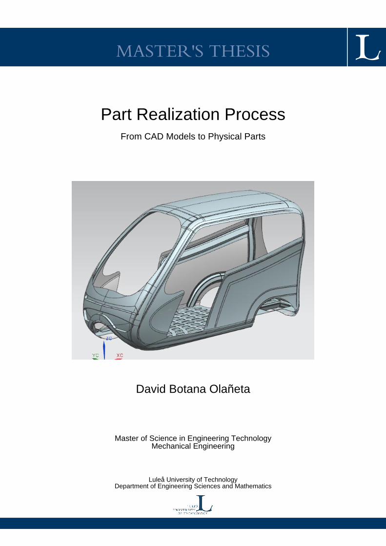
MASTER'S THESIS Part Realization Process From CAD Models to Physical Parts David Botana Olañeta Master of Science in Engineering Technology Mechanical Engineering Luleå University of Technology Department of Engineering Sciences and Mathematics
Transcript of From CAD Models to Physical Parts
MASTER'S THESIS
Part Realization ProcessFrom CAD Models to Physical Parts
David Botana Olañeta
Master of Science in Engineering TechnologyMechanical Engineering
Luleå University of TechnologyDepartment of Engineering Sciences and Mathematics

PART REALIZATION PROCESS.
FROM CAD MODELS TO
PHYSICAL PARTS
DAVID BOTANA OLAÑETA
DEPARTMENT OF ENGINEERING SCIENCES AND MATHEMATICS
SUPERVISOR: TORBJÖRN ILAR
LULEÅ UNIVERSITY OF TECHNOLOGY

PREFACE
This report is the written result of the Master Thesis performed during the academic year 2011-
2012. The work is part of a bigger project that aims the development of an auto-rickshaw for the
Indian market. Some sections of this Thesis were carried out together with Rubén Álvarez Villa
Master’s Thesis, Mapping and analyses of the process for auto-rickshaw manufacturing.
This Master Thesis has been developed under supervision of Torbjörn Ilar at the Department of
Applied Physics and Mechanical Engeneering at Luleå University of Technology, Sweden. The
work has been elaborate with information taken from GESTAMP HardTech AB in Luleå,
Sweden; a company specialized in pressing technologies. The support received from Hans
Bodin, Jan Larsson and Per-Emil Back from GESTAMP was really helpful to carry out this
thesis. The auto-rickshaw project group was also helpful, particularly Daniel Cook and
Christoffer Sveder; some of the first designs of the structure and the exterior design are taken
from them.
I would like to express my gratitude to Torbjörn Ilar for his support and advices. I also want to
thank Gustavo Peláez from University of Vigo for his guidance and support. Finally I would
like to thank my friends of Luleå and Galicia and my family.
Luleå, May 2012
David Botana Olañeta
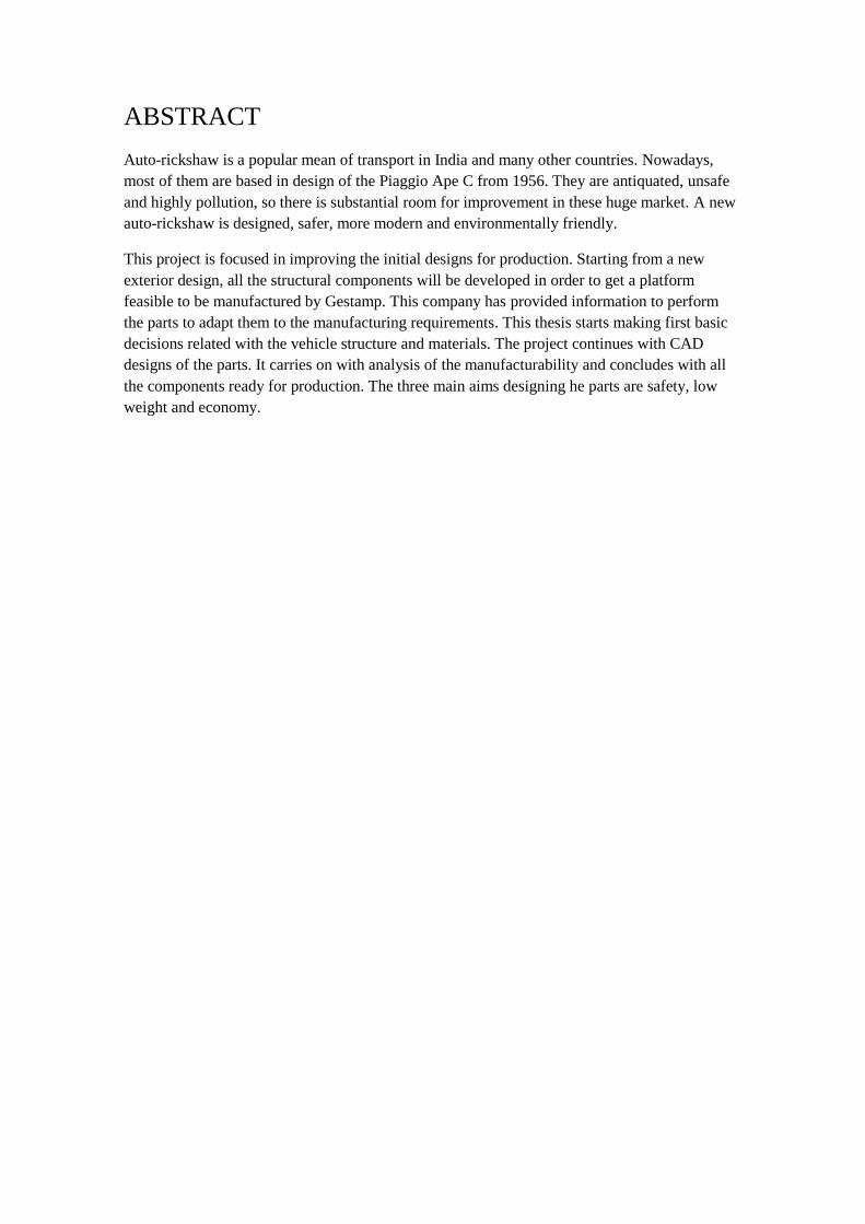
ABSTRACT
Auto-rickshaw is a popular mean of transport in India and many other countries. Nowadays,
most of them are based in design of the Piaggio Ape C from 1956. They are antiquated, unsafe
and highly pollution, so there is substantial room for improvement in these huge market. A new
auto-rickshaw is designed, safer, more modern and environmentally friendly.
This project is focused in improving the initial designs for production. Starting from a new
exterior design, all the structural components will be developed in order to get a platform
feasible to be manufactured by Gestamp. This company has provided information to perform
the parts to adapt them to the manufacturing requirements. This thesis starts making first basic
decisions related with the vehicle structure and materials. The project continues with CAD
designs of the parts. It carries on with analysis of the manufacturability and concludes with all
the components ready for production. The three main aims designing he parts are safety, low
weight and economy.

Table of contents 1 INTRODUCTION ................................................................................................................. 1
1.1 BACKGROUNDS ........................................................................................................ 1
1.2 PURPOSE AND GOALS ............................................................................................. 1
1.3 LIMITATIONS ............................................................................................................. 2
1.4 METHODOLOGY ........................................................................................................ 2
1.4.1 Working method .................................................................................................... 2
1.4.2 Project group ......................................................................................................... 2
1.4.3 Literature study ..................................................................................................... 2
1.4.4 Interviews .............................................................................................................. 2
1.4.5 Software ................................................................................................................ 3
1.5 TIME SHEDULE .......................................................................................................... 3
1.6 CURRENT AUTO-RICKSHAWS. MAIN PROBLEMS ............................................. 3
1.7 GENERAL SPECIFICATIONS FOR THE AUTO-RICKSHAW [1] [2] .................... 4
1.7.1 Geometry specifications ........................................................................................ 4
1.7.2 Force specifications ............................................................................................... 5
1.7.3 Materials specifications ......................................................................................... 5
1.7.4 Safety specifications .............................................................................................. 5
1.7.5 Other specifications ............................................................................................... 6
2 THEORY ............................................................................................................................... 7
2.1 TYPE OF STRUCTURE [3] ......................................................................................... 7
2.1.1 Monocoque ............................................................................................................ 7
2.1.2 Semimonocoque .................................................................................................... 8
2.1.3 Body on frame ....................................................................................................... 8
2.2 MATERIALS ................................................................................................................ 8
2.2.1 Structural beams materials .................................................................................... 8
2.2.2 Exterior sheets materials ....................................................................................... 9
2.3 MANUFACTURING PROCESSES ............................................................................. 9
2.3.1 Basic process in automotive industry [4] .............................................................. 9
2.3.2 Rolling process [5] .............................................................................................. 10
2.3.3 Laser cutting ........................................................................................................ 10
2.3.4 Nesting ................................................................................................................ 11
2.4 SHEET METAL FORMING ...................................................................................... 12
2.4.1 Basics of metal deformation [7] .......................................................................... 12
2.4.2 Conventional stamping [7] .................................................................................. 13
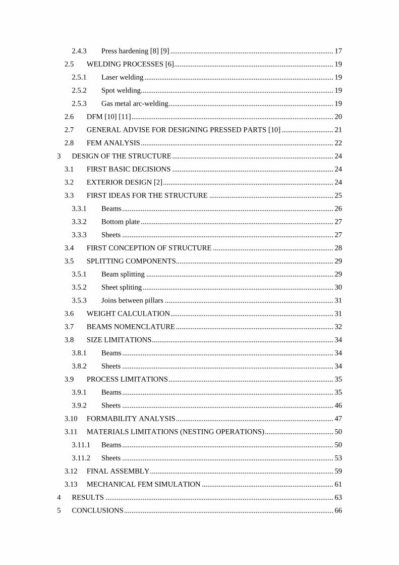
2.4.3 Press hardening [8] [9] ........................................................................................ 17
2.5 WELDING PROCESSES [6] ...................................................................................... 19
2.5.1 Laser welding ...................................................................................................... 19
2.5.2 Spot welding ........................................................................................................ 19
2.5.3 Gas metal arc-welding ......................................................................................... 19
2.6 DFM [10] [11] ............................................................................................................. 20
2.7 GENERAL ADVISE FOR DESIGNING PRESSED PARTS [10] ............................ 21
2.8 FEM ANALYSIS ........................................................................................................ 22
3 DESIGN OF THE STRUCTURE ....................................................................................... 24
3.1 FIRST BASIC DECISIONS ....................................................................................... 24
3.2 EXTERIOR DESIGN [2] ............................................................................................ 24
3.3 FIRST IDEAS FOR THE STRUCTURE ................................................................... 25
3.3.1 Beams .................................................................................................................. 26
3.3.2 Bottom plate ........................................................................................................ 27
3.3.3 Sheets .................................................................................................................. 27
3.4 FIRST CONCEPTION OF STRUCTURE ................................................................. 28
3.5 SPLITTING COMPONENTS ..................................................................................... 29
3.5.1 Beam splitting ..................................................................................................... 29
3.5.2 Sheet spliting ....................................................................................................... 30
3.5.3 Joins between pillars ........................................................................................... 31
3.6 WEIGHT CALCULATION ........................................................................................ 31
3.7 BEAMS NOMENCLATURE ..................................................................................... 32
3.8 SIZE LIMITATIONS .................................................................................................. 34
3.8.1 Beams .................................................................................................................. 34
3.8.2 Sheets .................................................................................................................. 34
3.9 PROCESS LIMITATIONS ......................................................................................... 35
3.9.1 Beams .................................................................................................................. 35
3.9.2 Sheets .................................................................................................................. 46
3.10 FORMABILITY ANALYSIS ..................................................................................... 47
3.11 MATERIALS LIMITATIONS (NESTING OPERATIONS) ..................................... 50
3.11.1 Beams .................................................................................................................. 50
3.11.2 Sheets .................................................................................................................. 53
3.12 FINAL ASSEMBLY ................................................................................................... 59
3.13 MECHANICAL FEM SIMULATION ....................................................................... 61
4 RESULTS ........................................................................................................................... 63
5 CONCLUSIONS ................................................................................................................. 66

6 FURTHER DEVELOPMENT ............................................................................................ 67
7 REFERENCES .................................................................................................................... 68
8 APPENDIX ......................................................................................................................... 70
8.1 FINAL COMPONENTS ............................................................................................. 70
8.2 TABLES OF WEIGHT CALCULATIONS ............................................................... 75
8.3 FORMABILITY ANALYSIS ..................................................................................... 77
8.4 FEM ANALYSIS ........................................................................................................ 81
8.5 STEEL SPECIFICATIONS ........................................................................................ 82

1
1 INTRODUCTION
1.1 BACKGROUNDS
The auto-rickshaw is a popular mean of transportation in India because of its low priced. An
auto-rickshaw is three wheels vehicle, generally characterized by a sheet-metal body or open
frame resting. One problem of these vehicles is the high level of pollution they produce. Driver
is placed in a small cabin in the front of the vehicle and the passengers sit in the rear. These
vehicles also can transport all kind of goods. The assignment of this global project is to design
and develop an auto-rickshaw, modern and less polluting.
One of the most important requirements is that the vehicle must have a low price. In order to
achieve this goal is necessary to use the optimal material and manufacturing process to ensure
the required quality with the lowest cost.
This Master thesis is a part of one multidisciplinary project that aims to develop a hybrid auto-
rickshaw for the Indian market. This multidisciplinary project includes the Sirius Auto-
Rickshaw student project, some Master theses and, hopefully more projects for several years.
Two companies provide information in this project: TVS, an Indian motor company; and
Gestamp Hardtech in Luleå, dedicated to manufacture automotive metal components.
Sirius is a final-year course for the Mechanical Engineering programme at Luleå University of
Techonology. The Sirius student group dedicated to the auto-rickshaw project has developed the
vehicle plataform. The concept report (Pre-studies of Hybrid Auto-rickshaw), final report
(Project Auto-rickshaw Report) and information of project group meetings are taken as a
reference to carry out this Master Thesis.
1.2 PURPOSE AND GOALS
The purpose of this Master thesis is to design the structural parts of the vehicle. The objective is
also to analyze what is the best way to manufacture all the parts of the auto-rickshaw structure.
To achieve this goal is necessary to redesign some features from the initial CAD model in order
to improve the manufacturing process and meet the mechanical requirements demanded. As it is
a low cost vehicle, it will seek to save the most possible money in the manufacturing.

2
1.3 LIMITATIONS
The project does not include the prototype design. It does not include the initial phases of the
product development process such as the exterior design. There are several structural parts
which are not included in this project, such as wheel covers, window frame and the suspension
anchorages.
1.4 METHODOLOGY
1.4.1 Working method
The working method of this Master’s Thesis consists on applying a combination of different
sources of information. First step is to obtain basic information of the subject through
manufacturing books and start using the software. Project group meetings are the way of take
information about the whole project. As the project progresses it becomes necessary to acquire
more specialized information such as some tutorials about the software tools, specialized
literature or direct interviews with Gestamp workers.
The methodology used in this project is starting from basic and easy designs of components.
Applying limitations, analyses and information of interviews, the basic designs become
complicated. Final parts are the result of continuous improvement.
1.4.2 Project group
Project group meetings provide basic information about the whole project. These meeting are
necessary to coordinate the work of each group of person inside the project. The contribution of
every person in the project group is available for the rest of the group if anyone needs it.
1.4.3 Literature study
The basic literature used in this project is about manufacturing processes. Manufacturing,
Engineering and Technology is one of the most used books in this report. Some books more
specialized in stamping process, like Tool and manufacturing engineers handbook, volume 2
Forming, were also consulted.
Apart from books, another source of information is scientific articles. Besides, some manuals
and tutorials about the software NX were used.
1.4.4 Interviews
Interviews and conversations with members of Gestamp Hardtech AB Luleå are a great source
of information. Advice, recommendations and feedback of information from Hans Bodin and
Jan Larson are basic in this project. In addition to this, the recommendations about forming by
Per-Emil Back are really useful to get the final components.

3
1.4.5 Software
During this project the software used is Siemens NX Unigraphics 8.0. It is used for designing all
the parts. It is also used to perform some analyses about formability and pressing process.
Siemens NX is also used to carry out Fem analysis. Throughout this report lots of images from
NX software are shown in order to clarify and explain the decisions taken.
1.5 TIME SHEDULE
Next table shows the main tasks in this project.
Figure 1. Time schedule
1.6 CURRENT AUTO-RICKSHAWS. MAIN PROBLEMS
Nowadays, there are about 5 million auto-rickshaws in India, which is approximately the 7% of
the motor vehicle registered in India. There are many different types of auto-rickshaw
depending on the use they are prepared. The most common auto-rickshaw is designed for
passenger transport in cities, as you can see in the picture.
The most typical structure of current auto-rickshaw is semi-monocoque. It consists of a base
platform made of steel with longerons and stringers. It also has some metal sheets and a canvas
roof attached by round tube.
The security is one of the main problems in Indian roads. According to National Crime Records
Bureau of India, there are more than 100 000 traffic fatalities in India every year and the 5, 6 %
off all road traffic deaths involve auto-rickshaw occupants. That means almost 6 000 fatalities
per year, and many more injured people.

4
Figure 2. Typical auto-rickshaw [1]
Most of the accidents take place in the cities and they are caused by collisions with other
vehicles. As can be seen figure 2, the typical auto-rickshaw for passenger transport is an open
frame where the passengers do not have any side protection. That is why is important to
improve the protection around the passengers and avoid, as far as possible, the impacts reach the
passengers.
Another unsafe situations driving auto-rickshaws is the rollover. An auto-rickshaw is a narrow
and high vehicle, and it has only three wheels so the rollover danger exists. Rollover also could
be induced by a side collision with other vehicle. Current auto-rickshaws usually have a canvas
roof. This is usually attached to the bottom plate with round tube that could not resist the efforts
in case of rollover. In this project we are going to improve that aspect to get more strength in
rollover.
1.7 GENERAL SPECIFICATIONS FOR THE AUTO-RICKSHAW [1] [2]
As the project is commissioned by a company, there are some specifications that must be
considered. Some of them are demanded by the company and some are wishes of the project
group. Most important specifications for this particular thesis are geometry specifications, force
specifications, materials specifications and safety specifications.
1.7.1 Geometry specifications
The geometry specifications describe the dimensions of the vehicle. It was decided that the new
auto-rickshaw should be approximately the same size as the old models. Some measurements
are taken from the TVS king, the most representative auto-rickshaw of the company. Measures
of the new model do not have to be exactly equal to demands, but should not differ much.

5
Table 1. Geometry specifications
Demand Wheel base 2000 mm
Demand Wheel track 1200 mm
Demand Overall length 2600 mm
Demand Overall width 1300 mm
Demand Overall height 1700 mm
Demand Ground clearance 170 mm minimum
Demand Turn radius Less or equal to present
models
1.7.2 Force specifications
These specifications should be used to adapt the construction of the vehicle to be able to
withstand various external forces.
Table 2. Force specifications
Demand Curb weight Maximum 300 Kg
Wish Load capacity 300 Kg
Demand Able to roll over
Demand Collision protection in the front,
sides and rear
Demand Be able to load on roof
Demand Be able to take bumps or running
down curbs
1.7.3 Materials specifications
There are some general wishes and demands about materials before decide exactly which
materials will be used.
Table 3. Materials specifications
Demand Minimum amount of heavy metals
Wish Environment friendly
Wish Recyclable
Wish Lightweight materials
Demand Easy to repair
1.7.4 Safety specifications
The safety specifications are a quite general list about how the users should be protected in case
of collision and overall safety measures.
Table 4. Safety specifications
Demand Built in deformation zones in body
Demand Allow personal safety device in vehicle
Demand Built in crash box structure in body
Demand Catastrophe breaker when handled
Demand Battery separator
Demand Waterproof systems during normal use in tropical environment.

6
1.7.5 Other specifications
One of the principal goals of the auto-rickshaw is a good fuel-efficiency, so it is really important
achieve the lowest possible weight. Another demand is to try that the auto-rickshaw is easily
repaired.
Another specification is the production cost of the vehicle, estimated on 1000 €, and the retail
price is demanded to be under 3000 €.

7
2 THEORY
2.1 TYPE OF STRUCTURE [3]
The chassis of a car is built to support the body. It includes the frame, wheels and working
components of the vehicle. The rigid structure of the frame provides protection during an
accident.
There are several types of vehicle structures. Structure selection is an important point, since it
will define all the following stages of the vehicle development. There are different choices,
monocoque, semimonocoque, body on frame. Other kinds of structures are suerleggera or
backbone chassis. Each one has advantages and disadvantages.
Nowadays, auto-rickshaws have a semi-monocoque chassis. It is a very simple structure that
consists on a combination of longerons and stingers supporting the weight of the metal sheets,
and the round tubes where the roof is attached. The chassis of the current auto-rickshaws is not
monocoque or independent chassis. Figure 3 shows the structure of one auto-rickshaw partially
disassembled in one of the laboratories of LTU.
Figure 3. An auto-rickshaw disassembled in LTU [2]
2.1.1 Monocoque
Monooque structures consist of sheets, beams or other kinds of metal components united by
welding and resulting in a rigid structure in one piece. Monocoque chassis are used nowadays
for the majority of the vehicles. It is efficient in terms of using space, so the interior space is
wide. It is not cost effective to manufacture them in small quantities; however t is easy to mass
produce. They might be economically produced due to the high automation which allows their
manufacture.

8
Monocoque structure uses more metal material than any other type of structure, consequently, it
is heavier. This structure is the best configuration to protect the passengers in rollover, and
generally in any kind of collision because it provides more stability in case of an accident.
Nevertheless, after having an accident the reparation is quite difficult. Less noise and vibration
are produced compared with any other type of structure. One disadvantage is that is difficult to
design different bodyworks from the same vehicle and any kind of reform in the structure are
almost impossible to implement.
2.1.2 Semimonocoque
Semimonocoque structure is quite similar to monocoque structure. The only difference is that
semimonocoque has longerons and stingers to make up a strength base. The other components
are attached to this base. Sometimes is difficult to differentiate it from monocoque structure.
2.1.3 Body on frame
Body on frame is the oldest structure system used and nowadays it only applies in the
construction of commercial vehicles and off road vehicles. It consists of two different structures:
the frame and the bodywork.
The frame is a structure consisting of one or more metal beams along the vehicle, connected by
crossbars welded, screwed or riveted, arranged transversely or diagonally. This element has a
high strength and the mechanical components and the bodywork are attached on it. The body
forms the outer shell of the vehicle and is screwed to the frame. It has not any strength feature.
This system allows some advantages. It has a great strength to carry heavy loads and a high
rigidity to withstand high elastic and dynamic stresses. This system also protects the bodywork
from bending or torsion efforts. The body on frame system has a great facility to use different
bodies in the same frame. Reforms in the body can also be performed easily.
2.2 MATERIALS
One of the most important decisions is to choose the type of material to be used. Depending on
the manufacturing process, the material used will vary. We can distinguish basically two groups
of parts with different requirement in the vehicle structure:
The structural beans, whose goal is to get a structure as strong and robust as possible.
The sheets, whose aim is, apart from providing resistance to the whole, enclose the
interior volume to protect it from the outside.
2.2.1 Structural beams materials
Materials used for beams should be strength, so metals are the most adequate material.
Conventional steel. It is a ductile material that can be manufactured with complex forms
and it present good welding properties. It is very economical. Nevertheless, it is

9
necessary to use greater thicknesses than other materials, which leads to a weight
increasing.
HSS (High speed steel). It has higher strength than conventional steel, so it is possible
to reduce the weight and increase the rigidity of the structure. They are lightly more
expensive and less ductile.
Boron alloyed steel. This kind of steel might be formed by hot-stamping. This method
allows good ductility during the process and high final rigidity. It is more expensive
than conventional steel.
Aluminum. It is lighter than steel and gets more strength with less weight. It presents
better corrosion resistance. However is more expensive than steel and it is more difficult
to weld.
2.2.2 Exterior sheets materials
Materials used for external sheets have less structural requirements.
Plastic material. It is a cheap material and easy to manufacture, but cannot be welded to
the structure and do not provide any strength to the assembly.
Fiberglas. It is a light material, but harder than plastic. It cannot be welded to the
structure and it is more expensive than plastic or sheet metal.
Sheet metal. It is a cheap material, provides strength and can be welded the assembly.
However, it is heavier than plastic.
2.3 MANUFACTURING PROCESSES
2.3.1 Basic process in automotive industry [4]
The automotive manufacturing processes play a major role in deciding on the vehicles design
characteristics and the overall cost. Thus it is very important for designers and engineers to
understand the current manufacturing infrastructure available in production lines. Designers
should consider the materials compatibility from the joining process welding point of view.
Additionally, designers should be aware that the vehicle design complexity in terms of number
of parts and intricate shapes results in additional manufacturing steps, which leads to greater
processing time and costs.
If designers are aware of basic process on the vehicle design, the result will be cheaper to
manufacture. These basic processes in an automotive production line are:
Laser cutting
Stamping and forming processes
Welding
Surface finishing and painting
Assembling of auxiliary elements
This Master Thesis is about the first three processes, focusing in stamping and forming
processes.

10
2.3.2 Rolling process [5]
Although rolling process is usually outside the layout in a vehicle factory and the steel coils are
considered as an input to the process, it is interesting to know their manufacturing process.
Rolling is a thickness reduction process or cross section reduction in a piece due to compression
forces. During the process, metal stock is passed through two or more of rolls.
Rolling process may be classified according to the process temperature: hot rolling or cold
rolling. There are several kinds of rolling process, but only flat rolling is interesting in this
project.
Flat rolling is the most basic way of rolling. The mechanical objective is simple; it is to reduce
the thickness. A single stand roughing mill is shown in the figure.
Figure 4. Rolling process [5]
2.3.3 Laser cutting
There are lots of cutting process can be applied for metal sheets, but laser cutting should be the
most useful process in this project. It can be used before and after the stamping process. The
laser beam diameter and power used in the cutting process depend of the material and thickness.
Basics of laser cutting consist on the light concentration on the work areas. As a result, a large
amount of heat melts the material on the required areas to cut the part.

11
Figure 5. Laser cutting head. Image from engineerstudent.co
Laser cutting is appropriate in a wide range of materials, including most of steel alloys.
However, is not best suited to metals such as aluminum and copper as they have good heat
conductive and light reflective properties. Laser cutting is suitable for very hard materials.
The reduction of material contamination as there is no real physical contact between metal and
cutter is one advantage of laser cutting. The laser can be focused into very small points in order
to get a great accuracy. The speed process is high compared with other cutting methods. There
is also a reduced chance of damaging the material because the affected area is small.
The high energy consumption and the high invest costs of installations is one disadvantage of
this process, so it is a quite expensive process. Another disadvantage is the maximum thickness
that can be processed by laser cutting, but is a suitable process to sheet cutting.
2.3.4 Nesting
Nesting is the process of efficiently distribution of parts from flat raw material. The sheet metal
nesting for flat sheets and nesting for coils are different algorithms. Material may be cut using
laser, punches, plasma, off-line blanking dies and even water jet cutters.
Nesting process can also provides an additional factor to select the optimal splitting between
two options. The more usual case is to choose between splitting something into more or fewer
components. Nesting process can be applied to place only one or several parts in the same sheet.
In order to minimize the amount of scrap raw material produced by this process, companies use
nesting software. The software analyses the parts (shapes) to be produced at a particular time.
When a wide range of shapes are required it is possible to enlist the help of special computer
programs to optimize the nesting of pieces so that optimum material utilization is achieved. This
is particularly important when the material is expensive. Next picture shows a typical result
from a nesting process.

12
Figure 6. Nesting example. Source SPAI software
2.4 SHEET METAL FORMING
Nowadays, sheet metal forming is one of the most important manufacturing processes in
industry. Sheet forming was used from 5000 B.C, when jewelry and household utensils were
made by hammering and stamping gold, silver and cooper. Sheet metal parts offer the
advantages of light weight and versatile shape. [6]
2.4.1 Basics of metal deformation [7]
In metal forming operations, work is performed within established limits, above the yield
strength and below the fracture strength, using forces that may be tensile, compressive,
shearing, or some combination. As a source of data relevant to formability, one of the most
useful tests is the tension test. In this test, a standard-shaped speciemen is used and the pulling
force is uniaxially applied. The primary output from the tension test is a measurement of the
load required to elongate the speciemen for each increment of elongation. Figure 7 shows a
classic engineering stress-strain curve.

13
Figure 7. Stress strain curve [7]
According to figure 7, there are several stages of deformation during the tensile test. The metal
first deform in an elastic manner (zone a). Loading or unloading to any point on the curved line
does not cause permanent or plastic deformation of the metal. The slope of this line is the
Young’s modulus of the metal.
At some stress value, called the yield strength, the metal reaches its proportional limit and starts
to deform plastically. This means that when the specimen is stressed beyond the yield strength
and unloaded, a permanent elongation remains. This elongation or deformation is uniformly
distributed along the gage section. An increase in load is required to deform the specimen an
additional increment of length and it causes a decrease of the specimen cross-section.
As the tensile specimen is elongated, the amount of work hardening decreases and the amount
of geometrical softening increases. When the two amounts balance each other, a load maximum
is reached (tensile strength) and deformation can continue under decreasing load. As the
specimen elongates, a reduction in width occurs. Then a localized neck is localized and finally
the specimen fractures.
In stretching a sheet of metal over a rigid punch, the post-uniform deformation is useful
deformation that makes a significant contribution toward producing an unbroken stamping.
Total formability, therefore, includes both uniform elongation and post-uniform elongation,
which is measured by the total elongation.
2.4.2 Conventional stamping [7]
Stamping is used as a general term to cover all press working operations on sheet metal; it is not
confined to forming or drawing processes. The stampings of parts from sheet metal is

14
straightforward operation in which the metal is shaped or cut through deformation by shearing,
punching, drawing, stretching, bending, coining, etc.
2.4.2.1 Shearing
Before a sheet-metal part is made, a blank of suitable dimension is first removed from a large
sheet, usually from a coil by shearing. Shearing is a cutting process performed between two
cutting edges; it does not form a chip. It may be a straight cut on a machine called squaring
shear or it may be done between a punch and die.
The principle of shearing is simply that as the blades come together and contact the material
being sheared, the blades penetrate the material until the tensile strength is overcome and a
crack of tear develops from both sides. Blade clearance has a considerable effect on the quality
of the sheared edge.
Figure 8. Shearing process. Image from custompartnet
There are two different kind of shearing: punching and blanking. In punching, the sheared slug
is discarded. In blanking, the slug is the part and the rest is scrap.
To be considered shearing, the cutting process must take place along a straight line on the work
piece. This limits the type of work performed on a shear. However, the shear is frequently used
to cut wide coils into large blanks, to cut coils into narrow strips, to square blank edges in order
to produce accurate blanks, and to cut parts to specific size.
Since shearing is chipless operation, waste scrap is reduced. Shearing process is fast because the
blades do not have to cut through the full thickness of the material, as it is required in some of
the typical metal cutting process. The accuracy of shear is high; nevertheless, secondary
operations to remove burrs from edges are sometimes necessary.

15
2.4.2.2 Bending and flanging
Bending and flanging are methods of forming shapes by stressing metal beyond its yield
strength but below the ultimate strength. Flanging is similar to bending of sheet metal, except
that, during flanging, the bent down metal is short compared to overall part size. There is no
well-defined bent-over length that distinguishes bending and flanging.
Bends are made in sheet metal to gain rigidity and to produce a part of desired shape to perform
a particular function. Bending is commonly used to produce structural stampings such as braces,
brackets supports, hinges, angles and channels. Bending is usually done to a 90º angle, but other
angles are also produced.
Figure 9. Bending operations [7]
Flanging is a narrow operation in which a narrow strip at the edge of a sheet is bent down along
a straight or curved line. Flanges are used for appearance, rigidity, edge strengthening and
removal of a sheared edge, as well as for an accurately positioned fastening surface. There are
three basic types of flanges, shown in figure 10: straight flange, stretch flange and shrink flange.
The jogged flange (figure f) is a combination of them.
Figure 10. Kinds of flanges [7]

16
Straight flange. It is a simple bend with no longitudinal stresses imposed on the material
except at the bend radius.
Stretch flange. It is unique in that flange has been stretched in the length direction
during the flanging operation. A stretch flanges forms with a concave outline (figure b),
a concave surface contour (figure c) or a combination of the two conditions.
Shrink flange. It is the opposite of the stretch flange, having shrunk in the length
direction during the flange operation. A shrink flange forms with a convex outline
(figure d), a convex surface contour (figure e) or a combination of the two conditions.
2.4.2.3 Drawing
Drawing is a process of cold forming a flat precut metal blank into a hollow vessel without
excessive wrinkling, thinning or fracturing. The various forms produced may be cylindrical or
box shaped, with straight or tapered sides or a combination of straight, tapered and curved sides.
The process of drawing basically involves forcing the flat sheet of metal into a die cavity with a
punch. The force exerted by the punch must be sufficient to draw the metal over the edge of the
die opening and into the die.
The metal being drawn must have a combination of strength and ductility. One of the factors
that determine whether the wall of a drawn part will rupture is the speed of deformation that the
metal can sustain. If the requirements cannot be obtained in the first drawing process, multiple
draws can be applied. Figure 11 shows a typical draw operation.
Figure 11. Draw operation [7]
2.4.2.4 Other stamping operations
Coining. It is the squeezing of metal while it is confined in a closed set of dies. A
movable punch is located within the die. The actions of this punch cold works the
material and can form intricate features.
Embossing. It is an operation for producing raised or sunken designs in sheet material
by means of male and female dies, theoretically with no change in metal thickness.
Ironing. This operation consists on the reduction in thickness of drawn shell walls by
pulling them through tight dies with compressive stress.
17
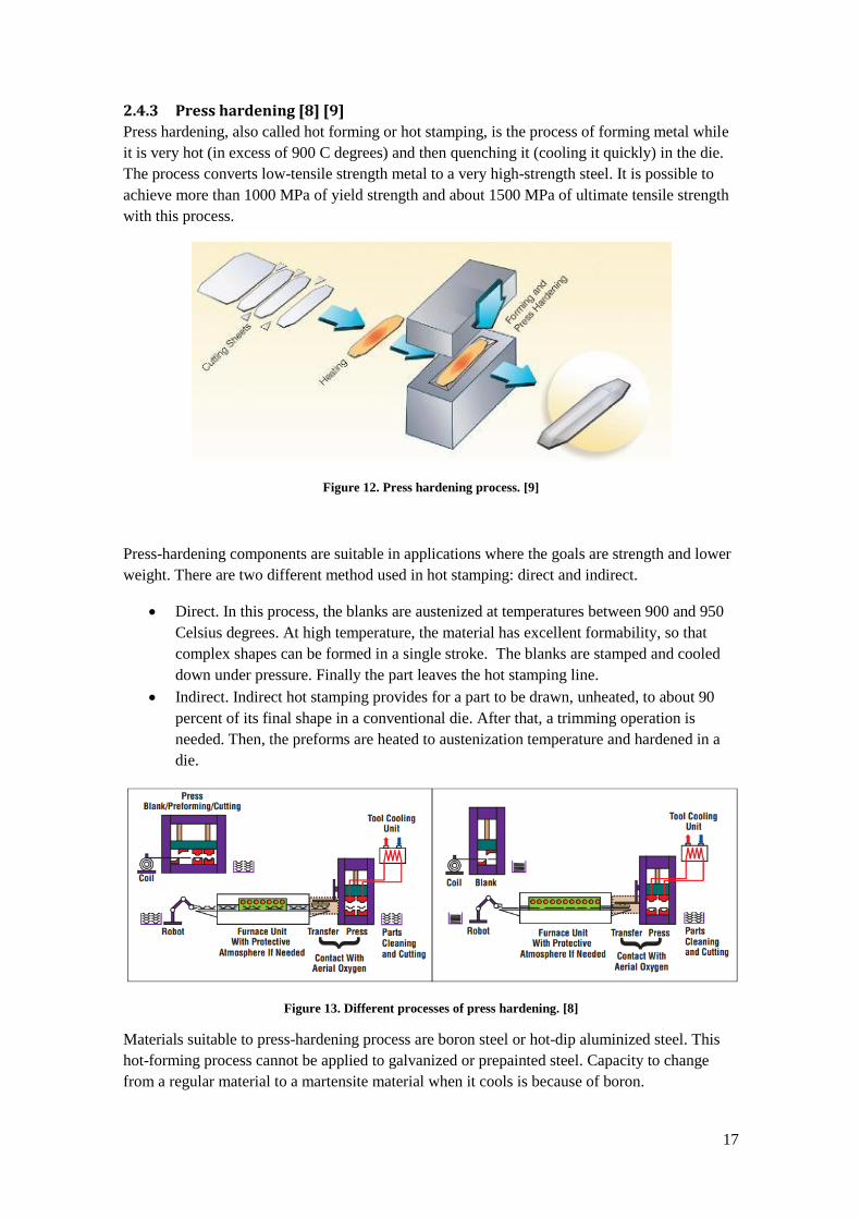
2.4.3 Press hardening [8] [9]
Press hardening, also called hot forming or hot stamping, is the process of forming metal while
it is very hot (in excess of 900 C degrees) and then quenching it (cooling it quickly) in the die.
The process converts low-tensile strength metal to a very high-strength steel. It is possible to
achieve more than 1000 MPa of yield strength and about 1500 MPa of ultimate tensile strength
with this process.
Figure 12. Press hardening process. [9]
Press-hardening components are suitable in applications where the goals are strength and lower
weight. There are two different method used in hot stamping: direct and indirect.
Direct. In this process, the blanks are austenized at temperatures between 900 and 950
Celsius degrees. At high temperature, the material has excellent formability, so that
complex shapes can be formed in a single stroke. The blanks are stamped and cooled
down under pressure. Finally the part leaves the hot stamping line.
Indirect. Indirect hot stamping provides for a part to be drawn, unheated, to about 90
percent of its final shape in a conventional die. After that, a trimming operation is
needed. Then, the preforms are heated to austenization temperature and hardened in a
die.
Figure 13. Different processes of press hardening. [8]
Materials suitable to press-hardening process are boron steel or hot-dip aluminized steel. This
hot-forming process cannot be applied to galvanized or prepainted steel. Capacity to change
from a regular material to a martensite material when it cools is because of boron.

18
Thanks to steadily rising vehicle safety and crash requirements in the automotive industry, the
use of ultrahigh-strength steels in structural and safety components is rapidly increasing. The
higher requirements for vehicle crash performance can be achieved with cold stamping only by
using thick-gauge steel, which results in weight increase. Cold stamping allows the production
of simple shapes with very high strength, up to 1,200 MPa, such as side impact beams.
Ultrahigh-strength steels, however, pose a major challenge in processing because of their
limited formability and pronounced springback at room temperature. So, when part complexity
increases, such as with B-pillars, only lower-strength steel grades can be used with cold
stamping.
Components with strength less than 1,000 MPa and complex shapes are manufactured in several
steps using progressive dies or transfer presses.
Press hardening has some advantages, such as a high tensile strength, an excellent plastic
deformation and good repeatability. The formed components have favorable welding
characteristics and there is not springback after the process.
Main disadvantages of press hardening process are the price of raw material (lightly higher than
conventional steel) and expensive and specific production equipment, such as a roller hearth
furnace and special dies.
Another disadvantage, according to information from the company, is an expensive post
processing if necessary. After pressing process, the material is very hard and only laser
trimming is allowed. This operation is required to achieve closed tolerances that probably are
not necessary in this project.
Typical hot forming components manufactured by Gestamp are structural car elements, such as
front and rear bumpers, side impact beams, A posts, B posts, floor and roof reinforcements and
cross members. Next picture show some press hardening components in a car.
Figure 14. Press hardening components. Images from Gestamp
A decision, if a component is manufactured using hot or cold forming depends on whether a
cost or weight objective is prioritized for the vehicle. If the cost objective is prioritized, then
cold forming is used. With rising degrees of component complexity using cold forming only
low strength materials can be manufactured. Consequently, complex shapes and high demand of
19
strength leads to use hot forming. In case of a weight objective in connection with a high
demand on strength (concerning vehicle safety), the hot forming method predominates.
2.5 WELDING PROCESSES [6]
Welding is a manufacturing process that joins materials, usually metals or thermoplastics by
causing coalescence. There are many different welding processes. The selection of the best
welding process for each application depends on lots of conditions, such as material, thickness,
shapes, automation, finishing…
Some of the most typical welding process in automotive industry are laser welding and spot
welding because the easy automation for mass production. Gas metal-arc welding might be used
also in this project. These processes will be used in auto-rickshaw assembly.
2.5.1 Laser welding
Laser welding utilizes a high-power laser beam as the source of heat to produce a fusion weld.
The beam can be focused precisely to a very small area; it has high-energy density and,
therefore, has deep penetrating capability. This process is particularly suitable for welding deep
and narrow joint. There are several types of lasers used in manufacturing operations: CO2,
Nd:YAG. Nd:glas, ruby…
The reflectivity and thermal conductivity of the work piece surface and the specific heat and
latent heat of melting and evaporation are important physical factors in laser welding. The
surface obtained is usually rough and has a heat-affected zone which might be treated.
2.5.2 Spot welding
Spot welding is the most common process from resistance welding. Resistance welding is the
heating junction to be welded by local resistance to passage of electric current. The material is
raised to a temperature that causes it actually to melt and, under pressure; it is fused or forged
together.
Spot welding consists on joining two pieces of material by placing them between two
electrodes. The time of applications and current must be calculated to allow the join. The most
common application of spot welding is in the automobile manufacturing industry, where it is
used almost universally to weld the sheet metal to form a car. Spot welders can also be
completely automated, and many of the industrial robots found on assembly lines are spot
welders.
2.5.3 Gas metal arc-welding
In this welding process the weld area is shielded by an external source, such as argon, helium,
and carbon dioxide. There is a consumable bare wire that is fed automatically through a nozzle
into the weld arc.

20
Gas metal arc-welding is rapid, versatile, and economical; and the process can easily be
automated and lends itself readily to robotics and flexible manufacturing systems.
2.6 DFM [10] [11]
Design for manufacturability (also sometimes known as design for manufacturing) - (DFM)
is the general engineering art of designing products in such a way that they are easy to
manufacture. The basic idea exists in almost all engineering disciplines, but of course the details
differ widely depending on the manufacturing technology
Engineers are generally not taught on DFM, we are trained to design parts, not products or
systems. Most engineers focus primarily on functionality which gets a product into the game.
Products need to be produced at high quality and reliability. The product will have to be priced
competitively, which then means that profits will be determined by the cost and it is very
difficult to reduce the cost after the product is designed. Therefore, most profits are determined
by how well low cost can be assured by design; this is design for manufacturability.
In order to design for manufacturability, everyone in product development team needs to
understand how products are manufactured through experience in manufacturing, training, rules,
and multifunctional design. If the product will be built by standard processes, design teams must
understand them and design for them. If processes are new, then design teams must
concurrently design the new processes as they design the product.
Early consideration of manufacturing issues makes product development time shorter. It also
minimizes development cost, and ensures a smooth transition into production and reduced time
to market. Many costs are reduced, since products can be quickly assembled from fewer parts.
Thus, products are easier to build and assemble, in less time, with better quality. DFM
encourages standardization of parts, modular design, and standard design features.
The design determines the manufacturability. By the time a product has been designed, only
about 8% of the total product budget has been spent. But by that point, the design has
determined 80 % of the lifetime cost of the product. Cost reduction programs should start with
product design, because it has the most influence over the overall cost.
The main benefits of DFM are:
Lower production cost.
Higher quality
Quicker time to market
Lower capital equipment cost
Greater automation potential
Production up to speed sooner
Fewer engineering changes
Fewer parts to purchase from fewer vendors
Factory availability

21
2.7 GENERAL ADVISE FOR DESIGNING PRESSED PARTS [10]
Pressed parts must satisfy several conditions in order to be manufactured. There are some basic
ideas to achieve a good shape and are going to be used on the structure design later. Next figure
illustrate a section through a drawn shell. Shape in the left should be avoided if possible, the
right shape is preferred.
Figure 15. Profile recommendations [10]
Left profile has these problems:
The width-to-height ratio is poor.
The radii are too small.
The walls are parallel, requiring subsequent operations such as multiple redrawing and
ironing.
There is a very high probability of fractures.
Material having excellent drawing properties will be required, increasing cost.
The necessary mechanical work requires a large energy input.
Heat and friction may result in metal pickup problems.
Extreme-pressure drawing lubricants may be required.
The process is very sensitive to stock thickness and material property variations.
Inspection costs may be high if necking prior to fracture is not permitted in the part.
These facts are applied for conventional forming. Press-hardening can avoid some of the
problems, such as lubricants use.
The part shown in the right is a better stamping.
The width-to-height ratio is good.
The metal is drawn over generous radii.
The draw walls are open. The side walls of a safe stamping should have six degrees of
taper per side as a minimum rule (press-hardening stamping may have a lesser angle).
A stamping of this configuration can tolerate a wide range of material conditions.
Less lubrication is required.
Simpler tools are used.

22
Another good recommendation designing a profile is avoiding bend radii lesser than sheet
thickness. The corner radius of a profile should be also no more than one-third of the draw
depth. Avoiding deep drawing conditions leads to a reduction tooling and material costs. There
are benefits rated to surface finish of the parts as well.
Being able to form a part in a die is not the only requirement. It must also be possible to get the
part out of the die after it is formed. The parts shows in next picture can be made in expensive
multiple-hit tooling and they are difficult to take out of the die. [10]
Figure 16. Profiles that should be avoided [10]
It is theoretically possible to form these shapes in single stage process having complicated cam-
slide mechanisms and sliding mandrels. The tool costs might exceed that of simple U-forming
five or ten times. Tooling maintenance costs are higher as well.
2.8 FEM ANALYSIS
Finite elements method (FEM) has been gradually replacing traditional validating which
consists of building a prototype and test it. If the test reveals problems with the design of the
mechanical requirements, the design should be changed and a new prototype should be built and
tested. It is an interactive, expensive and time-consuming process.
FEM analysis do not substitute traditional validation, it is only a complement to reduce time and
costs in validation process. With FEM analysis is possible simulate the product performance in
a virtual environment, identify and remedy potential problem areas before building a prototype
and reduce product development costs and time.
The finite element method is a numerical technique used to find approximate solutions of partial
differential equations and integral equations. The solution approach consists of eliminating the
differential equation completely or rendering the partial differential equations into an
approximating system of ordinary differential equations. Then, these equations are numerically
integrated using standard techniques as Euler’s Method and Runge-Kutta. Computing
processing is essential when the geometry is not basic.

23
In this project, FEM analysis will be used to check if the designed components withstand the
mechanical requirements. The methodology uses the following steps.
1. Obtain a part
2. Select solver
3. Idealize the geometry
4. Create a mesh
5. Apply boundary conditions (such as constraints and forces)
6. Solve model
7. Review results.
24
3 DESIGN OF THE STRUCTURE
This section develops the design of the auto-rickshaw structure. First step must be to take some
basic decisions about the type of structure, materials and manufacturing methods. After that, the
design starts trying to adapt the beams to the external shape of the vehicle. Then, the
components are split and its thickness selected. Next step consist in applying some limitations to
make feasible the production in the factory such as size limitations, process limitations,
formability analysis and nesting. Finally, some basic FEM analysis ale developed.
First steps of the design (3.1 to 3.4) were developed cooperating with the project group. Next
sections (3.5 to 3.9) are developed exclusively in this Master’s Thesis. Sections 3.10 to 3.12
were carried out together with Ruben Álvarez Villa and his Master’s Thesis Mapping and
analyses of the process for auto-rickshaw manufacturing. Last section (3.13) is a basic FEM
analysis for further development.
3.1 FIRST BASIC DECISIONS
Some basic decisions must be taken at the beginning of the project development, such as the
type of structure, the manufacturing processes and the materials used. These three decisions
must be taken together. The materials must be adequate to use the manufacturing processes
selected.
Type of structure. Monocoque structure will be selected. Using this structure the auto-
rickshaw will be safer and adequate for mass production.
The main manufacturing processes used will be press hardening for beams and
conventional stamping for sheets. Press hardening is used because structural beams
need the maximum strength, reduced weight and complex shapes. Stamping process is
the most suitable manufacturing process to form the parts of the shell.
Materials. According to the manufacturing processes selected the suitable materials will
be boron alloyed steel for beams and steel rolled for sheets. Commercial steels provided
by SSAB Company suitable for this project may be Docol 1500 Bor for press hardening
and Docol 500 for conventional stamping. Specifications for these steels can be
consulted in Appendix 5.
3.2 EXTERIOR DESIGN [2]
Before designing the structure frame, the exterior shape of the auto-rickshaw is designed. After
that, the exterior final design could be modified if necessary during the design phase of the
structure.

25
After lots of drafts of possible options for the external design was reached. The exterior design
of our auto-rickshaw is new, unlike anything so far in the world of auto-rickshaw. Design of
current auto-rickshaws is based on Piaggio Ape C from 1956, and even new designs are not so
different of that model. The new design of the auto-rickshaw (figure 17) is cool and aggressive
to call upon potential buyers.
One of the main features is lacking the B-pillar and having an open rear for easy entry and exit
of passengers. The final design was created in Alias software and looks like in the images below
(figure 17). After that, the surfaces will be exported to Siemens NX to design the structural
components from the external shapes created.
Figure 17. Exterior design of the auto-rickshaw [2]
3.3 FIRST IDEAS FOR THE STRUCTURE
The structure of the auto-rickshaw might be divided into bottom plate, structural beams and
sheet metal pieces. As it is a monocoque structure, every part collaborates to create a resistant
vehicle, but the main hardness is applied because of the beams. All the parts are going to be
joined together.
It has been considered to use the minimum number of different materials and thicknesses to
reduce costs. Therefore, all the beams will have the same thickness. Sheets also can be
manufactured with the same thickness. Nevertheless, a singular piece may have a different
thickness if necessary.

26
3.3.1 Beams
The beams are the basic parts in case of collision. They have to protect the passengers around
any direction of the space. With the information supplied by the company to the project group, a
profile for the beams was chosen. Figure 18 shows the basic shape of the profile, as well as the
dimensions used approximately. The thickness of the beams was taken as 1.5 mm taking into
account the recommendations of the company. They usually use thicknesses between 1.2 mm to
2mm in press-hardening processes. In some cases, the shape of the profile might be slightly
modified in order to adapt the beams to the shape of the bodywork.
Figure 18. Basic profile of the beams
There were also some different options with respect to beams. First option was made the beams
external parts. That means they should be painted and prepared as the external sheets, so it
makes them more expensive. One advantage is that the sheets are directly joined to the beams;
consequently, there are not joins between two sheets. However, external beams have more
complexity shapes. In the other hand, the internal beams have easier shapes and probably higher
stiffness, so that is the solution taken.
A first draft of beams was made (figure 19). The goal at this stage was to have a first approach
about where place the beams. The shape profile and de the shape of the whole auto-rickshaw is
not taken into account. It is necessary to keep free the entry and exit of the vehicle, so there are
not so many options to place the beams.
Figure 19. Draft of the beams [2]

27
3.3.2 Bottom plate
The bottom plate is the basic part of the vehicle. It needs to support the whole weight of the
vehicle components, such as engine, batteries, seats…, as well as the passengers and loads.
First of all, some drafts of different ideas were made. It was consider designing a double hot-
forming sheet, but finally, the option selected was one quite simple, based on a long medium
beam from the front to the back of the vehicle and two transverse beams in each side (figure
20). Above it, a big flat sheet is placed. All this components have to support a big load so these
parts will be dimensioned consequently. The beams and the floor sheet should have a thickness
of 1,5mm.
Figure 20. Bottom plate
3.3.3 Sheets
The shape of the sheet body was directly taken from the model. The cavities prepared for rear
lights and direction indicators on the sides were not taken into account because these cavities
make the sheet shapes more complicated. The solution is cutting the piece of material necessary
to attach the lights after pressing.
The thickness chosen for the sheets was 1mm; a quite high steel sheet thickness, but necessary if
we want the sheets to create stiffness to the structure. The sheet splitting will be analyzed later.
The whole sheet looks like in figure 21.
Figure 21. Exterior sheet of the vehicle
28
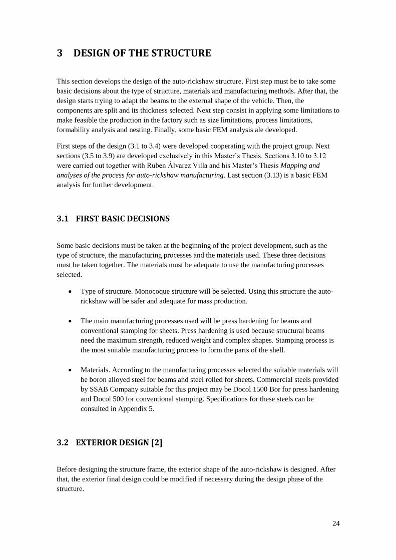
3.4 FIRST CONCEPTION OF STRUCTURE
At this stage, we have enough information to create a first conception of the final structure.
What we have to do is to apply the profile shown in figure 18 to the draft of beams location
shown in figure 19 and adapt it to the whole external shape shown in figure 21. The resulting
structure should fit inside the external sheet. The result is shown below in figure 22.
Figure 22. Design of structural beams
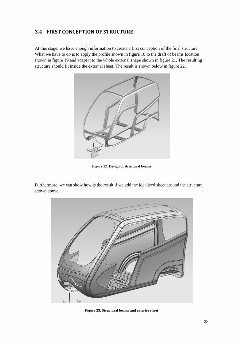
Furthermore, we can show how is the result if we add the idealized sheet around the structure
shown above.
Figure 23. Structural beams and exterior sheet

29
3.5 SPLITTING COMPONENTS
There are lots of ways of splitting the structures, so it is not an easy task finding the perfect
solution. There are many determining factors involved in the splitting activity. As a result there
are some steps before the last solution. We are going to separate the splitting in two groups:
beams and sheets.
3.5.1 Beam splitting
The first stage of beam splitting is quite logical. At first appearance is easy to select some basic
components. At this stage we are going to get fewer components as possible. Then we might
split some of them. One condition taken into account was not to join three beams in the same
intersection in order to get an easier welding. At the same time, it is necessary to think how to
join the split beams. The next image shows an exploded view of the first structure spitting.
Figure 24. Beam splitting
As we can see in the picture, there is a long beam in the bottom plate. We think this part is the
most important in the structure, so it should be only one component. There are also two lateral
beams on either side joint by four transversal beams.
On the front there are three beams of varying heights. The front wheel cover is solved with two
beams. On each side of the vehicle, there are also three curved beams of varying height. On the
rear there is a rectangle shape split on the middle plane, getting two symmetrical components.
After these splitting we can see some parts that maybe are difficult to manufacture. These
questions will be analyzed later. In Appendix 1 all the parts (final designs) are shown
separately.

30
3.5.2 Sheet spliting
The most important feature splitting the idealized sheet imported from the exterior design is to
get the minimum number of components, as big as possible and as flat as possible. If we have
many sheets, logically we will have many joins between them. These joins will be solved later,
but is interesting to have the minimum length of this joins. If we have big and irregular
components we will waste too much raw material.
At the beginning we are going to obtain the bigger components as possible. Then some
limitations will force us to get more parts. Figure 25 shows the exploded view of first stage of
sheet splitting.
Figure 25. Sheet splitting
There are three basic sheets, the floor, the roof and the front. The floor sheet has a thickness of
1.5 mm, 0.5 mm thicker than the rest of the parts, and it has a special hollow to place the
batteries. The roof sheet is important to manufacture in one piece because safety reasons, for
instance to be stronger if the vehicle roll over. The front sheet has the most complex shape, but
seems feasible to manufacture in only one part.
We can find more options splitting the sheet on the sides and on the back. At this stage, the
solution decided was to split each side in three parts and the back in two parts. This solution
might waste too much raw material.

31
3.5.3 Joins between pillars
The beams will be joined with spot welding. For this issue, according to information provided
by some staff of the company, is necessary to have a clearance on the beam flanges of at least
10 mm, but 20 mm would be better. To achieve this goal, it is necessary to add some tabs to the
beams. We show some examples in figure 26.
Figure 26. Different tabs: continuous (left) and discontinuous (right)
We can distinguish two different kinds of tabs, continuous tabs, which provide a complete
surface to weld the join all around the beams, and discontinuous tabs, which provide only some
places to apply the welding. First one part is more strength than second one, and provides a
bigger surface able to weld. The problem is that using these tabs might appear difficult angles to
the manufacturing processes. Consequently, we are going to apply continuous tabs if possible.
Later, we are going to check if it is possible to manufacture the parts. One advice from the
company is not to bend the material in many directions and try to design the tabs without
changing the main direction of the beams when possible.
3.6 WEIGHT CALCULATION
At this moment of the development of the vehicle is important to make a calculation of the
amount of material used until this moment. NX software provides a fat method to calculate the
weight of the components. We take as density reference 7850 kg/m3. One project specification
is to achieve a total weight maximum of 300 kg. Besides, we know that the weight of the
structural components in a vehicle is about 30 – 40 % of the total weight. As a result, the weight
of the beams and the sheets should be between 100 and 120 kg as much. We also have to take
into account that we are not considering the weight of the wheel houses, the suspensions
anchors, window frame and some more parts.

32
Next table indicates the weight of the components distinguishing between sheet parts, floor
sheet and structural beams (including the beams of the bottom plate) and indicating also the
thickness in each case. The complete table which specifies the weight of each component is
shown in appendix 2.
Table 5. Weight calculation 1
number thickness (mm) weight (kg)
Beams 20 1,5 59,03
Floor 1 1,5 28,63
Sheets 10 1 57,56
TOTAL WEIGHT 145,22
The final result of 145 kg is unacceptable. Consequently it is necessary to save material in some
parts. The structural beams contribute further to the strength of the assembly so we are not
going to modify them. We can reduce the thickness of the sheets to 0.6 mm that is still a good
size in automotive conventional industry. We can also reduce the thickness of the floor plate
from 1.5 mm to 1 mm. These reductions will cause a weaker assembly. Even so, the auto-
rickshaw looks to be stronger than current ones. The complete table is shown in appendix 2 as
well.
Table 6. Weight calculation 2
number thickness (mm) weight (kg)
Beams 20 1,5 59,03
Floor 1 1 19,09
Sheets 10 0,6 34,54
TOTAL WEIGHT 112,65
These modifications achieve a new weight of 112 kg, which is more optimal than the previous
weight. It means a reduction of 22%. Consequently, we will take these last thicknesses: 1.5 mm
for beams and 0.6 mm for sheets, except the floor sheet which is 1 mm thick.
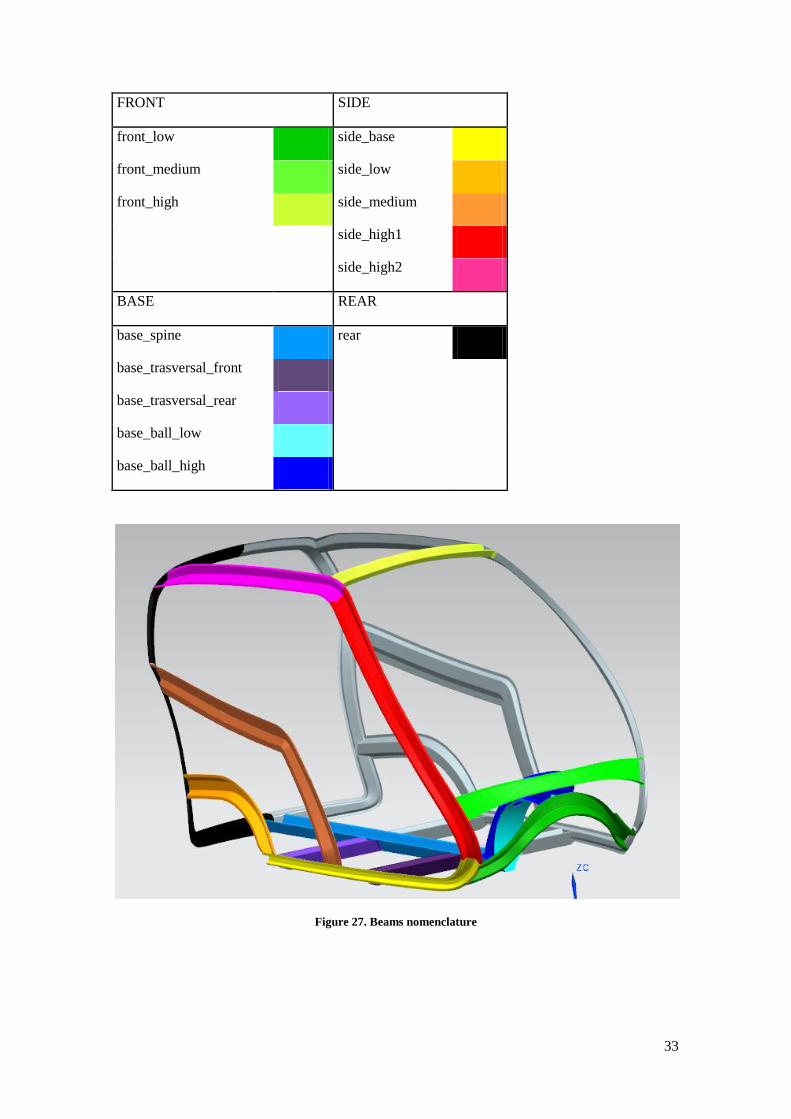
3.7 BEAMS NOMENCLATURE
At this stage of the project might be interesting show what beams we have and how to group
and call them. Each component has a different color in the image. Grey components are
symmetrical respect another parts, so they are not taken into account.
33
FRONT SIDE
front_low side_base
front_medium side_low
front_high side_medium
side_high1
side_high2
BASE REAR
base_spine rear
base_trasversal_front
base_trasversal_rear
base_ball_low
base_ball_high
Figure 27. Beams nomenclature

34
3.8 SIZE LIMITATIONS
3.8.1 Beams
First limitation in a press manufacturing process is the size of the press tool. Bigger presses
have higher operation costs and tool costs. According information of the factory, the biggest
hard-pressing tool has a size of 1500 mm. It is possible to manufacture parts until 2200 mm
placing the component at an angle to take advantage of the entire volume of the press. In these
cases, the manufacturing costs are higher so 1500 mm is a good reference about the dimensions
of press-hardening components.
Taking into account the beam splitting shown before, we can find some beams with one
dimension bigger than 1500 mm. Four of them (side_base beam, both rear beams and
side_medium beam) exceed 1500 mm only a small amount; about 100 mm, so it seems easy to
place it properly and they should not have any problem in pressing process. The long spine is
2050 mm along X-axis. Nevertheless, we reaffirm our decision to manufacture the component
in only one piece, although it will be more expensive.
The long side beam is too long to press in only one part; the length is 2800 mm (about 3100 mm
following the path of the beam). It is necessary to split the beam into two parts. We must realize
not to split the component at the same place the front pillar is joint, in order to do not have three
components welded in the same point. Besides, we must add some extra tabs to join the two
parts of the long beam. The result is shown in figure 28.
Figure 28. Side_high beam splitting
3.8.2 Sheets
The sheets will be manufactured by conventional pressing. Conventional press tools are more
common than press-hardening tools, so they have less size restrictions. All the sheets considered
have an adequate size for big presses. All of them might be manufactured in a press with a
35
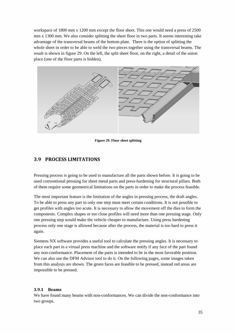
workspace of 1800 mm x 1200 mm except the floor sheet. This one would need a press of 2500
mm x 1300 mm. We also consider splitting the sheet floor in two parts. It seems interesting take
advantage of the transversal beams of the bottom plate. There is the option of splitting the
whole sheet in order to be able to weld the two pieces together using the transversal beams. The
result is shown in figure 29. On the left, the split sheet floor, on the right, a detail of the union
place (one of the floor parts is hidden).
Figure 29. Floor sheet splitting
3.9 PROCESS LIMITATIONS
Pressing process is going to be used to manufacture all the parts shown before. It is going to be
used conventional pressing for sheet metal parts and press-hardening for structural pillars. Both
of them require some geometrical limitations on the parts in order to make the process feasible.
The most important feature is the limitation of the angles in pressing process, the draft angles.
To be able to press any part in only one step must meet certain conditions. It is not possible to
get profiles with angles too acute. It is necessary to allow the movement off the dies to form the
components. Complex shapes or too close profiles will need more than one pressing stage. Only
one pressing step would make the vehicle cheaper to manufacture. Using press hardening
process only one stage is allowed because after the process, the material is too hard to press it
again.
Siemens NX software provides a useful tool to calculate the pressing angles. It is necessary to
place each part in a virtual press machine and the software notify if any face of the part found
any non-conformance. Placement of the parts is intended to be in the most favorable position.
We can also use the DFM Advisor tool to do it. On the following pages, some images taken
from this analysis are shown. The green faces are feasible to be pressed, instead red areas are
impossible to be pressed.
3.9.1 Beams
We have found many beams with non-conformances. We can divide the non-conformance into
two groups.

36
Non conformance because of the tabs added to weld. In these cases, if tabs are removed,
the part would be feasible to press. However, this cannot be the solution. In order to
solve the problem it is possible to have a new splitting, make same modification on the
tabs or change the welding method.
Non conformance because of the shape of the beam. In these cases, the curves of the
part cause that it is impossible to achieve some faces during pressing process. The
solution might be modifying the shape of the beam or splitting it in smaller parts.
3.9.1.1 Base plate
These parts only present small non conformances because of the tabs. The main spine has not
non-conformances, it has simple shapes. Nevertheless it should be pressed inclined to be able to
form the rear tabs. This position is required as well to manufacture the part in a press smaller
than itself.
The beams around the front wheel (ball_high and ball_low) have not also non-conformances.
Both transversal beams are difficult to manufacture because of the tabs connected to lateral
beams. It is possible, according to current technology, to manufacture this part using
complicated cam slides or mandrels which provide extra movements in the dies. However, it
would be too expensive so these shapes are not feasible. Instead, it seems to be easy to remove
some material on the tabs maintaining an adequate contact surface with lateral beams for
welding. The non-conformances of one of these beams and the solutions are shown in figure 30.
Figure 30. Wrong draft angles in bottom transversal beams (left) and solution (right)
3.9.1.2 Side
There are five parts in this group (taking into account that the high beam has been divided into
two parts). Three of them, side_base, side_low and side_medium, have not any problems during
pressing process. These parts are shown in APENDIX 1. Two remaining parts (side_high_1 and
side_high_2) present some non-conformances in the tabs. The non-conformances in tabs might
be manufactured in only one stage using complicated and expensive tools, so they should be
avoided.
On the part side_high_2 appears one non-conformance on the tab added on the previous section
splitting the component (figure 31, left). If we try to replace the part in the press machine in

37
order to avoid those problems, new non-conformances appear in the tabs placed in the opposite
end of the part. Consequently, it is necessary to delete the tabs on one of the ends.
On the part side_high_1, not only appears the non conformance on the tabs between the two
beams, but also appears one non-conformance at the junction between this part and
side_base(figure 31, right).
Figure 31. Wrong draft angles in side_high beams
After considering several solutions, it was decided to eliminate the tabs between both beams
(side_high_1 and side_high_2). The solution adopted is to set up an overlap between the parts.
The overlap clearance is 30 mm, enough to guarantee an appropriate welding. In the same way,
the tabs between side_high_1 and side_base is deleted and replaced with an overlap junction.
The result is shown in figures 32 and 33.
Figure 32. Overlap joint between side_high beams
38
Figure 33. Overlap joint between side_high_1 and side_base
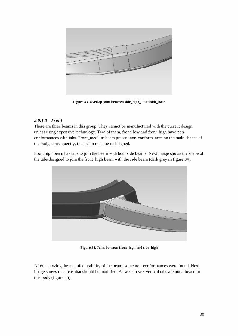
3.9.1.3 Front
There are three beams in this group. They cannot be manufactured with the current design
unless using expensive technology. Two of them, front_low and front_high have non-
conformances with tabs. Front_medium beam present non-conformances on the main shapes of
the body, consequently, this beam must be redesigned.
Front high beam has tabs to join the beam with both side beams. Next image shows the shape of
the tabs designed to join the front_high beam with the side beam (dark grey in figure 34).
Figure 34. Joint between front_high and side_high
After analyzing the manufacturability of the beam, some non-conformances were found. Next
image shows the areas that should be modified. As we can see, vertical tabs are not allowed in
this body (figure 35).
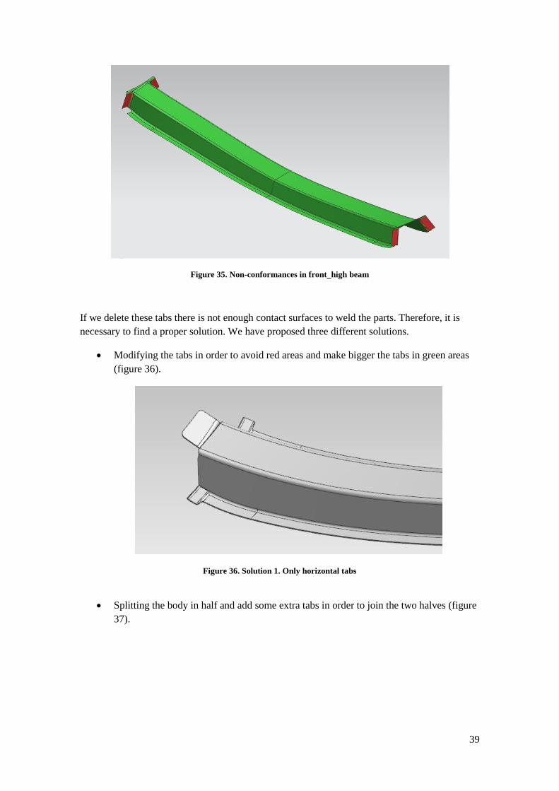
39
Figure 35. Non-conformances in front_high beam
If we delete these tabs there is not enough contact surfaces to weld the parts. Therefore, it is
necessary to find a proper solution. We have proposed three different solutions.
Modifying the tabs in order to avoid red areas and make bigger the tabs in green areas
(figure 36).
Figure 36. Solution 1. Only horizontal tabs
Splitting the body in half and add some extra tabs in order to join the two halves (figure
37).

40
Figure 37. Solution 2. Part split in half.
Making and extra operation for bending vertical tabs (figure 38).
Figure 38. Solution 3. Extra bending operation
After proposing these three alternatives in a meeting in the factory, we preferred to take solution
1. Solution 2, splitting the part into the middle would be more expensive because it requires an
overlap spot welding to join the two halves. This operation adds some important extra costs
because it needs more raw material and some extra welding spots. Solution 3 is not really
feasible because the difficulty of having any operation after press hardening. After this process,
the material is very hard and any operation would be really expensive.
Selected solution has the problem of the reduction in tabs area, which leads to a weaker
welding. It is possible to make bigger the horizontal tabs in order to provide a greater welding
surface. The final solution is shown in figure 39.

41
Figure 39. Final solution to front_high beam
Front_low beam present also some problems in tabs. Although the shape of this part seems to be
complex, this part would be feasible to manufacture avoiding again vertical tabs, as we can see
in figure 40.
Figure 40. Non-conformances found in front_low beam
The solutions might be quite similar to last part because the non conformances found are due to
the same subject. In this case, splitting the part does not seem to be an adequate solution
because this part acts as a bumper and might appear a weaker zone in the middle of the part.
Consequently, we will select the same solution as in the previous part. The result is shown in
figure 41.

42
Figure 41. Join point between side_base and front_low beams
Front_medium beam is impossible to press with current design. The part has not only non-
conformances with tabs, but also with the shape of the profile. The problem was trying to make
the beam fits perfectly into the cavity of the front sheet. Thereby, a closed profile (stronger than
open ones) is obtain in one of the areas of the vehicle where is necessary to have more
resistance (figure 42).
Figure 42. Image of the front section
As we can see on the draft angle analysis shown in figure 43, it is really difficult to manufacture
this part in one press step, because the area that need an additional move during the pressing
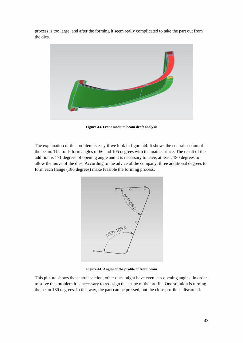
43
process is too large, and after the forming it seem really complicated to take the part out from
the dies.
Figure 43. Front medium beam draft analysis
The explanation of this problem is easy if we look in figure 44. It shows the central section of
the beam. The folds form angles of 66 and 105 degrees with the main surface. The result of the
addition is 171 degrees of opening angle and it is necessary to have, at least, 180 degrees to
allow the move of the dies. According to the advice of the company, three additional degrees to
form each flange (186 degrees) make feasible the forming process.
Figure 44. Angles of the profile of front beam
This picture shows the central section, other ones might have even less opening angles. In order
to solve this problem it is necessary to redesign the shape of the profile. One solution is turning
the beam 180 degrees. In this way, the part can be pressed, but the close profile is discarded.
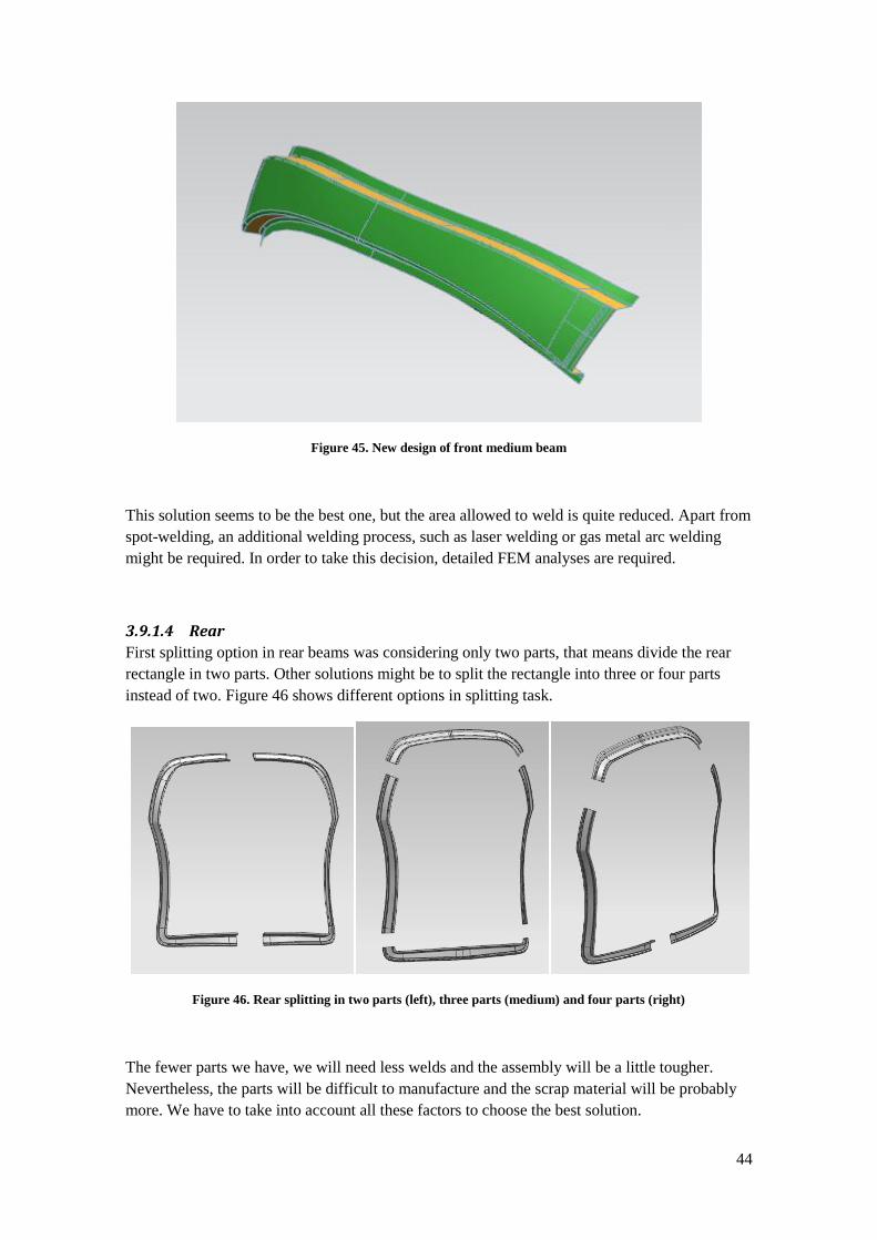
44
Figure 45. New design of front medium beam
This solution seems to be the best one, but the area allowed to weld is quite reduced. Apart from
spot-welding, an additional welding process, such as laser welding or gas metal arc welding
might be required. In order to take this decision, detailed FEM analyses are required.
3.9.1.4 Rear
First splitting option in rear beams was considering only two parts, that means divide the rear
rectangle in two parts. Other solutions might be to split the rectangle into three or four parts
instead of two. Figure 46 shows different options in splitting task.
Figure 46. Rear splitting in two parts (left), three parts (medium) and four parts (right)
The fewer parts we have, we will need less welds and the assembly will be a little tougher.
Nevertheless, the parts will be difficult to manufacture and the scrap material will be probably
more. We have to take into account all these factors to choose the best solution.
45
The first solution is impossible to press in only one stage according to the results of the draft
analysis shown in figure 47.
Figure 47. Draft analysis of two-part splitting way
Next option, the three parts splitting is possible to press in only one stage according to the
results of the draft analysis.
However, it is impossible to use tabs contained in perpendicular plane to the beam, so overlap
tabs should be used as shown in pictures below. It is important to realize that the two lateral rear
parts are not symmetric after this modification. Next two pictures (figure 48) show the tabs to
weld the three parts.
Figure 48. Overlaps tabs in rear components

46
Splitting the rear structure into four parts is logically also possible. It is necessary to check the
nesting operations to select the final solution, but much material should be saved with the four-
part option in order to select this option instead of three-part splitting.
3.9.2 Sheets
All the sheets are supposed to be manufactured by conventional pressing. Using this process
draft angles must be correct. If any non-conformance appears, the piece needs at least two
pressing steps, leading to an increase of the manufacturing costs.
After analyzing all the sheets in the assembly, almost all of them can be manufactured in only
one press stage. Most difficult parts to form are the front sheet and the floor sheets. They have
difficult draft angles that are going to be analyzed.
The front sheet has two cavities, one for lights and another to the air entrance. There are some
yellow painted surfaces when analyzing draft angles (figure 49). Yellow areas are feasible to
manufacture, however they are close to the limit and deformation in the material might be too
high. However, is not required any modification. Further analysis might conclude that two
pressing stages are necessary to manufacture this part.
This part might be manufactured by press-hardening because of its complex shapes. It will be
expensive, but the strength of this part is also really important. If further FEM analyses
conclude that the frontal strength of the vehicle should be improved the hot-forming would be
the best solution.
Figure 49. Draft analysis of front sheet
The floor sheet was designed with certain roughness for prevent slipping. Wall angles were
designed 90 degrees inclined. This is the limit in forming process so these walls are red-painted
in the figure 50.

47
Figure 50. Draft analysis of floor sheet
It is necessary to redefine the wall angles in order to make possible the pressing process. It is
easy because these shapes are not functional and there is not any restriction. Consequently the
angles were increased three degrees approximately to make feasible the forming process (figure
51).
Figure 51. Redesigned floor sheet
The rest of the sheets do not have any problematic wall angles.
3.10 FORMABILITY ANALYSIS
Any forming process leads a deformation in the material. After the process, the material is
stressed. Too much stressed areas should be avoided. After deformation process some areas of
the parts reduce their thickness, it may even lead to fracture. Too thick areas should be avoided
48
as well. These facts are really important in conventional forming. Hot-forming is a different
process where material is easier to form because of the high temperature of the process. That is
why these analyses are not so important. Thickness reduction and stressed areas are smaller than
using conventional forming.
NX software has a specific tool which calculates the stress, strain and thickness in each point of
the part after the pressing process. This tool is quite useful for sheet metal parts manufactured
by conventional forming. For structural beams manufactured by press-hardening is a helpful to
find which are the most stressed areas or which features are most difficult to form, however,
numeric results are not valid in this case.
All the sheet parts were subjected to a formability analysis. One of the most important results of
the analysis is the thickness reduction. We can establish a limit in thickness reduction after the
forming process in a 15% to ensure there is enough material in the entire sheet surface. Next
pictures show two thickness graphics after a formability simulation. Parts shown are the side
sheet and the roof sheet. The rest of the formability analyses are shown in Appendix 3.
Figure 52. Roof formability analysis
Figure 53. Side sheet formability analysis
Table 7 shows the thickness maximum reduction for each sheet metal part.

49
Table 7. Thickness reduction of sheet parts
Part Initial thickness
(mm)
Minimum thickness
after pressing (mm)
% of thicknees
reduction
floor_1 1 0,719 28,1
floor_2 1 0,789 21,1
side_front 0,6 0,598 0,3
side 0,6 0,599 0,2
side_low 0,6 0,596 0,7
rear 0,6 0,596 0,7
roof 0,6 0,591 1,5
front 0,6 0,210 65,0
There are three components with too much thickness reduction: the sheets of the floor and the
front sheet. The rest of the components have a thickness reduction less than 2%.
The floor might be modified in order to improve the thickness reduction. The solution is to
increase the walls angles modified in chapter 3.8.2. If these angles are increased 20 degrees
(view figure 54) the forming process would be easier.
Figure 54. Changed wall angles in floor sheet
After applying this change the thickness reduction is improves as seen in table 8.
Table 8. Thickness reduction modifications of floor sheets
Part Initial thickness
(mm) Minimum thickness after pressing (mm)
% of thicknees reduction
floor_1 1 0,895 10,5
floor_2 1 0,885 11,5
These new results for the floor sheets are more adequate. Nevertheless, the thickness reduction
of the front sheet seems difficult to improve until an adequate percentage. The solutions are the
same proposed in chapter 3.8.2: a two-stage pressing process or a hot forming process.

50
3.11 MATERIALS LIMITATIONS (NESTING OPERATIONS)
All the pressed components need to have their own nesting analysis in order to get the minimum
scrap material. There is specific software used to nest components. As we do not have this
software, we will implement a simplified analysis using NX software. We assume that the scrap
material is not used to manufacture any small component. More detailed analysis might
consider different nesting options in order to exploit the resulting gaps. For these tasks,
specialized software must be used.
First step is flatting the components; it means to convert the three-dimensional surface into a flat
surface. Siemens NX software provides a tool to do it, at least for conventional pressing. Press-
hardening components have a different deformation process so the result may vary slightly. As
it is not a detailed analysis; the results will be rough.
Next step consists on placing the flat components into a rectangular surface simulating a steel
coil. Most used coils are 1.5 meter wide. We are going to use only this coil size to make the
analysis easier. We are going to place each component in different positions and find which the
best option is. Finally the scrap material is calculated comparing the component surface and the
raw material used.
We are not going to calculate all the nesting components. It is a laborious task so we are going
to make nesting on those components where there are several splitting options in order to select
the most efficient splitting.
Nesting calculations were made in Excel software. The results are displayed in several
comparative tables. A reference length (L) is displayed in each nesting option (L1, L2, L3…).
NX software measures the area of each part (S). The wide is of the sheet in the coil is called w,
and it a fixed amount (1500 mm). The number of parts enclosed in the area w*L was called n.
With these elements is possible to calculate the scrap rate, which means the percentage of raw
material wasted, 30 % is a good rate, 50% is a bad rate. It is possible to calculate as well the
amount of material wasted per component. These rates are approximate, but they are a good
advice in order to select best nesting option.
3.11.1 Beams
All the beams will be manufactured used press-hardening so the results of the flatten surfaces
are not exact. . Structural beams have lots of limitations, so the final design of them is quite
limited. There are only different splitting choices in the rear zone.
3.11.1.1 Rear
There are two ways of splitting the rear structure; it is possible to split it in three or four parts.
Four-part structure will have four welds, one more than the three-part structure. As a result,
three-part structure will be cheaper to assembly. Nevertheless, the three-part structure may need
fewer raw materials. Nesting analysis will check which option waste less raw material. Four-
part splitting will be profitable only if much raw material is saved. The upper beam is the same
in two structures, the rest are different.

51
Figure 55. Three and four part splitting options
First component in nesting analysis is the L-beam (component 1). Despite the two L-
components are lightly different only one will be analyze to simplify the task. It has a
complicate shape to place the components on the sheet so four different nesting options were
proposed. Component 2 is the side beam in four-part splitting option and it is placed in three
different positions on the coil. Component 3 is the low beam in four-part splitting and it is
placed in two different positions. Next three pictures (figures 56, 57 and 58) show these nesting
options.
Figure 56. Nesting component 1 of rear beams

52
Figure 57. Nesting component 2 of rear beams
Figure 58. Nesting component 3 of rear beams
Table 9 shows all data required and the Scrap rates calculated for each option.
Table 9. Nesting calculations of rear beams
Comp Option
(placing) w
(mm) S
(mm2) L
(mm) n SCRAP (%)
SCRAP (mm2/comp)
3-PART SPLITTING
1 1 1500 175477 1900 6 63,1 299523
1 2 1500 175477 2350 10 50,2 177023
1 3 1500 175477 3048 12 53,9 205523
1 4 1500 175477 1806 9 41,7 125523
4-PART SPLITTING
2 1 1500 110285 1350 10 45,5 92215
2 2 1500 110285 960 8 38,7 69715
2 3 1500 110285 1350 12 34,6 58465
3 1 1500 135611 1100 9 26,0 47722
3 2 1500 135611 1150 9 29,2 56056
Three-part splitting consists of two “components 1” and one upper component that is not
considered because is the same in both splitting options. As can be seen in the table, option 4 is
the best way of placing the components because it has the lower scrap percentage (41.7%).
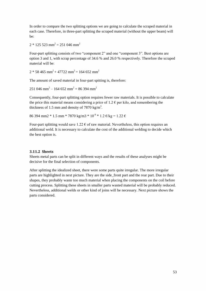
53
In order to compare the two splitting options we are going to calculate the scraped material in
each case. Therefore, in three-part splitting the scraped material (without the upper beam) will
be:
2 * 125 523 mm2 = 251 046 mm
2
Four-part splitting consists of two “component 2” and one “component 3”. Best options are
option 3 and 1, with scrap percentage of 34.6 % and 26.0 % respectively. Therefore the scraped
material will be:
2 * 58 465 mm2 + 47722 mm
2 = 164 652 mm
2
The amount of saved material in four-part spitting is, therefore:
251 046 mm2 – 164 652 mm
2 = 86 394 mm
2
Consequently, four-part splitting option requires fewer raw materials. It is possible to calculate
the price this material means considering a price of 1.2 € per kilo, and remembering the
thickness of 1.5 mm and density of 7870 kg/m3.
86 394 mm2 * 1.5 mm * 7870 kg/m3 * 10-9
* 1.2 €/kg = 1.22 €
Four-part splitting would save 1.22 € of raw material. Nevertheless, this option requires an
additional weld. It is necessary to calculate the cost of the additional welding to decide which
the best option is.
3.11.2 Sheets
Sheets metal parts can be split in different ways and the results of these analyses might be
decisive for the final selection of components.
After splitting the idealized sheet, there were some parts quite irregular. The more irregular
parts are highlighted in next picture. They are the side_front part and the rear part. Due to their
shapes, they probably waste too much material when placing the components on the coil before
cutting process. Splitting these sheets in smaller parts wasted material will be probably reduced.
Nevertheless, additional welds or other kind of joins will be necessary. Next picture shows the
parts considered.
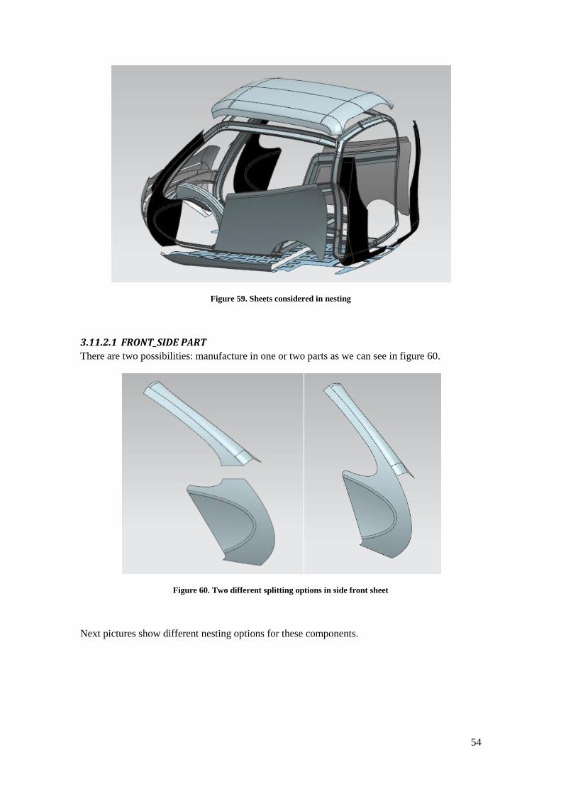
54
Figure 59. Sheets considered in nesting
3.11.2.1 FRONT_SIDE PART
There are two possibilities: manufacture in one or two parts as we can see in figure 60.
Figure 60. Two different splitting options in side front sheet
Next pictures show different nesting options for these components.

55
Figure 61. Nesting of non-split side front sheet
Figure 62. Nesting of split part, component 1
Figure 63. Nesting of split part, component 2
The scrap material calculations are shown in table 10.
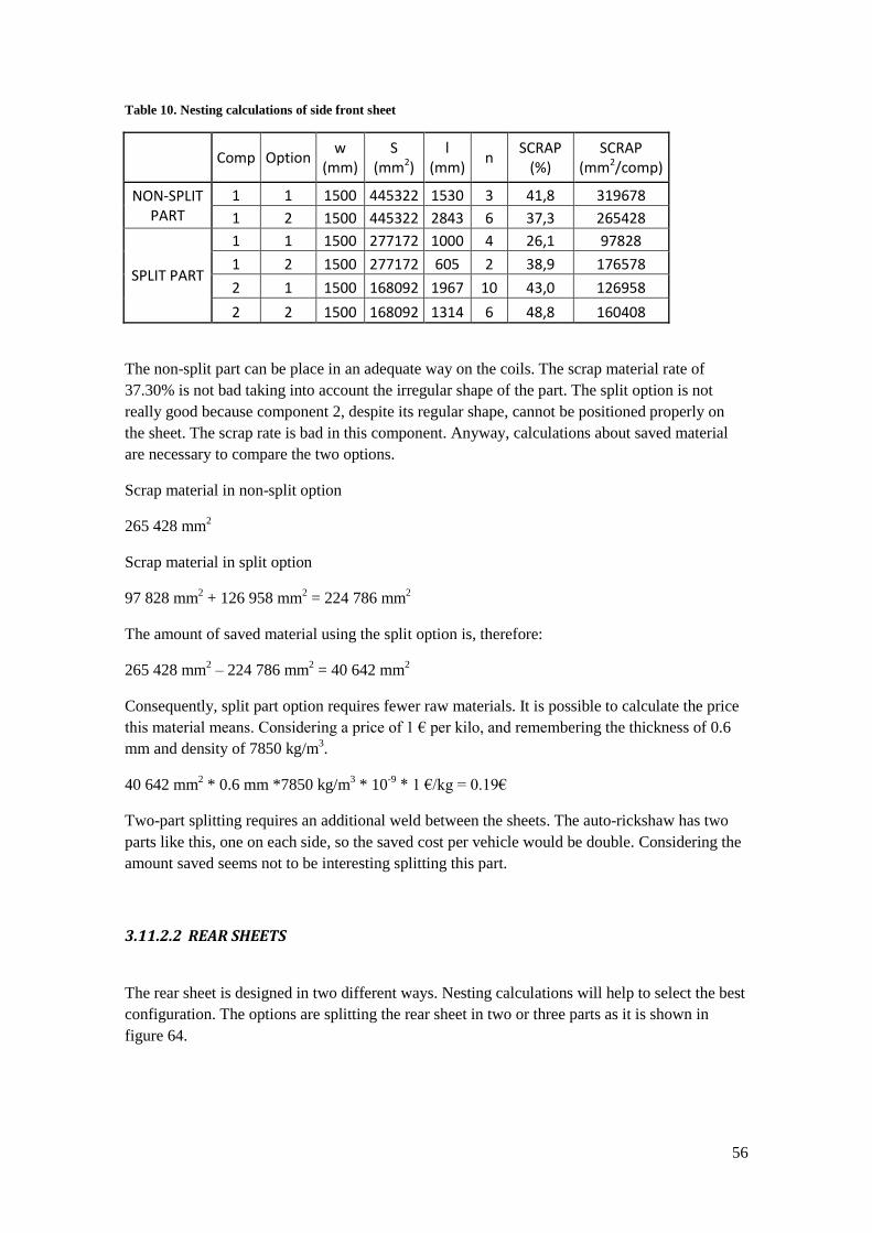
56
Table 10. Nesting calculations of side front sheet
Comp Option w
(mm) S
(mm2) l
(mm) n
SCRAP (%)
SCRAP (mm2/comp)
NON-SPLIT PART
1 1 1500 445322 1530 3 41,8 319678
1 2 1500 445322 2843 6 37,3 265428
SPLIT PART
1 1 1500 277172 1000 4 26,1 97828
1 2 1500 277172 605 2 38,9 176578
2 1 1500 168092 1967 10 43,0 126958
2 2 1500 168092 1314 6 48,8 160408
The non-split part can be place in an adequate way on the coils. The scrap material rate of
37.30% is not bad taking into account the irregular shape of the part. The split option is not
really good because component 2, despite its regular shape, cannot be positioned properly on
the sheet. The scrap rate is bad in this component. Anyway, calculations about saved material
are necessary to compare the two options.
Scrap material in non-split option
265 428 mm2
Scrap material in split option
97 828 mm2 + 126 958 mm
2 = 224 786 mm
2
The amount of saved material using the split option is, therefore:
265 428 mm2 – 224 786 mm
2 = 40 642 mm
2
Consequently, split part option requires fewer raw materials. It is possible to calculate the price
this material means. Considering a price of 1 € per kilo, and remembering the thickness of 0.6
mm and density of 7850 kg/m3.
40 642 mm2 * 0.6 mm *7850 kg/m
3 * 10
-9 * 1 €/kg = 0.19€
Two-part splitting requires an additional weld between the sheets. The auto-rickshaw has two
parts like this, one on each side, so the saved cost per vehicle would be double. Considering the
amount saved seems not to be interesting splitting this part.
3.11.2.2 REAR SHEETS
The rear sheet is designed in two different ways. Nesting calculations will help to select the best
configuration. The options are splitting the rear sheet in two or three parts as it is shown in
figure 64.

57
Figure 64. Two different spitting option of rear sheet
The shapes of the components in two-part split option are more irregular so it is supposed to
waste more raw materials. In the other hand, the three-part split option will need an additional
weld. Next pictures (figures 65, 66 and 67) show different nesting options for each component.
Figure 65. Nesting of two-part splitting option
Figure 66. Nesting of three-part splitting option, component 1

58
Figure 67. Nesting of three-part splitting option, component 2
The scrap material calculations are shown in table 11.
Table 11. Nesting calculations of rear sheets
Comp Optio
n w (mm)
S (mm2)
l (mm)
n SCRAP
(%) SCRAP
(mm2/comp)
REAR SHEET IN 2
COMPONENTS
1 1 1500 382678 930 2 45,1 314822
1 2 1500 382678 1410 3 45,7 322322
1 3 1500 382679 1702 4 40,0 255571
REAR SHEET IN 3
COMPONENTS
1 1 1500 266457 1165 4 39,0 170418
1 2 1500 266457 582 2 39,0 170043
2 1 1500 232517 1310 5 40,8 160483
2 2 1500 232517 857 4 27,6 88858
The components of the two-part split option have a scrap rate of 40 % using nesting option 3.
The raw material wasted is:
2 * 255 571 mm2 = 511 142 mm
2
The components in three-part split option have better scrap rates. The scrap material amount is:
2 * 170 043 mm2 + 88 858 mm
2 = 428 944 mm
2
The amount of saved material using the three-part split option is, therefore:
511 142 mm2 – 428 944 mm
2 = 82 198 mm
2
Consequently, split part option requires fewer raw materials. It is possible to calculate the price
this material means considering a price of 1 € per kilo, and remembering the thickness of 0.6
mm and density of 7850 kg/m3.
82 198 mm2 * 0.6 mm * 7850 kg/m3 * 10
-9 * 1 €/kg = 0.39 €
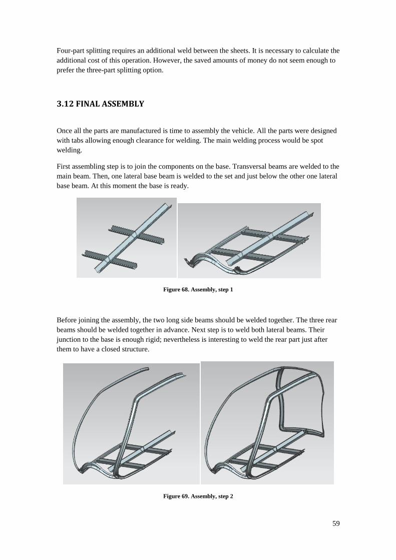
59
Four-part splitting requires an additional weld between the sheets. It is necessary to calculate the
additional cost of this operation. However, the saved amounts of money do not seem enough to
prefer the three-part splitting option.
3.12 FINAL ASSEMBLY
Once all the parts are manufactured is time to assembly the vehicle. All the parts were designed
with tabs allowing enough clearance for welding. The main welding process would be spot
welding.
First assembling step is to join the components on the base. Transversal beams are welded to the
main beam. Then, one lateral base beam is welded to the set and just below the other one lateral
base beam. At this moment the base is ready.
Figure 68. Assembly, step 1
Before joining the assembly, the two long side beams should be welded together. The three rear
beams should be welded together in advance. Next step is to weld both lateral beams. Their
junction to the base is enough rigid; nevertheless is interesting to weld the rear part just after
them to have a closed structure.
Figure 69. Assembly, step 2
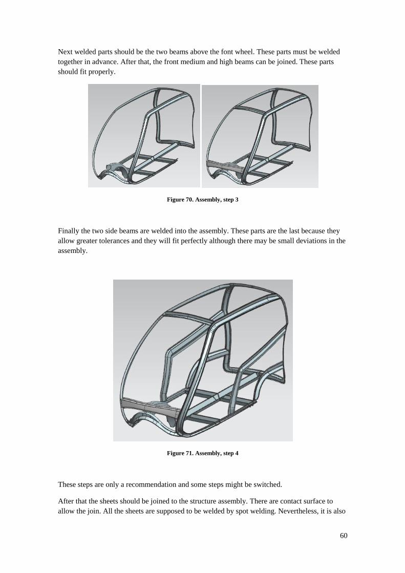
60
Next welded parts should be the two beams above the font wheel. These parts must be welded
together in advance. After that, the front medium and high beams can be joined. These parts
should fit properly.
Figure 70. Assembly, step 3
Finally the two side beams are welded into the assembly. These parts are the last because they
allow greater tolerances and they will fit perfectly although there may be small deviations in the
assembly.
Figure 71. Assembly, step 4
These steps are only a recommendation and some steps might be switched.
After that the sheets should be joined to the structure assembly. There are contact surface to
allow the join. All the sheets are supposed to be welded by spot welding. Nevertheless, it is also

61
possible to screw the sheets to the structure assembly simply by replacing the welding points
with screws. Anyway, the joints will be visible because might be expensive hide them. There is
not any special order to join the sheets to the structure.
3.13 MECHANICAL FEM SIMULATION
After designing the structural components, they should be tested in order to meet the mechanical
requirements. These tasks require a detailed analysis of each part and the entire assembly. FEM
analysis is a good task to further development in this project. Nevertheless, some basic analysis
will be carried out to have some basic ideas about the strength of the vehicle.
Only single parts were analyzed because analyze the assembly would require the simulations of
the welding joints. Also the sheet metal parts should be taken into account in FEM analysis of
the vehicle because they provide some strength to the entire assembly. NX provides lots of
information after FEM analysis. Next two pictures shows the deformation of front_low and
side_low beams after applying a 40 000 N force in the middle point of the beams. More
deformation results are shown in Appendix 4.
Figure 72. Deformation FEM analysis o front_low beam
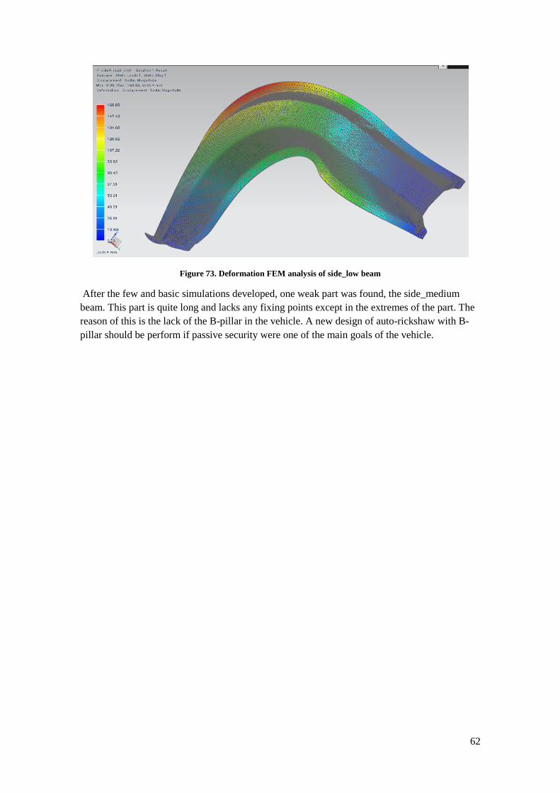
62
Figure 73. Deformation FEM analysis of side_low beam
After the few and basic simulations developed, one weak part was found, the side_medium
beam. This part is quite long and lacks any fixing points except in the extremes of the part. The
reason of this is the lack of the B-pillar in the vehicle. A new design of auto-rickshaw with B-
pillar should be perform if passive security were one of the main goals of the vehicle.

63
4 RESULTS
All the structural parts of an auto-rickshaw were designed in this project starting from the
exterior design. It includes the structural beams and the exterior shell formed by sheet metal
parts.
All the components were designed and analyzed in order to be manufactured. The final result of
the assembly with “real” parts is very similar to the exterior design proposed. After the
developed work, the following final components have been obtained
23 structural beams to make up the main structure of the vehicle, with a thickness of 1.5
mm. They will be manufactured by press-hardening
2 sheets with a thickness of 1 mm placed on the floor of the auto-rickshaw. They will
manufactured by conventional stamping.
10 sheets with a thickness of 0.6 mm to enclose the volume of the vehicle. They will be
manufactured by conventional stamping.
Figure 74 shows the final result of the assembly.
Figure 74. Final assembly
Figures 75 and 76 show the beams structure assembled and an explosion of the sheets.

64
Figure 75. Final assembly, exploded view of sheets 1
Figure 76. Final assembly, exploded view of sheets 2

65
Other obtained results are the analysis and simulations used for improving the components. In
this project only more interesting analysis were shown.

66
5 CONCLUSIONS
Designing a vehicle structure is an iterative process. There are many conflicting
objectives and it is difficult to achieve all desired goals. A vehicle structure should be
strength, light, safe, easy to manufacture… It is impossible to get all these purposes, so
it necessary to obtain a good balance between all the parameters.
Basic decisions, such as type of structure and material and manufacturing process used
are really important. If one of the decision taken is incorrect leads to change almost
everything in the project. Consequently these basic decisions should be taken by the
whole project group after a detailed analysis.
There are lots of different solutions for an auto-rickshaw structure. Components
designed may be improved for sure, and maybe the report contents errors due to
inexperience.
Used methodology appears to be adequate. Starting with a first design of the
components and improving it applying different kind of restrictions, such as size
limitations, manufacturing restrictions, saved raw material…
All the components proposed were designed and are feasible to manufacture and meet
basic requirements of strength, weight and cost.
The results demonstrate that is possibly to manufacture an auto-rickshaw complete
different to current ones, improving some features and probably with a good price.
CAD-CAM software (Siemens NX in this project) is a powerful tool, almost essential
for design components and analyzes their shapes, manufacturability, strength…
67
6 FURTHER DEVELOPMENT
Improved FEM analysis. Modify the beams (thickness and shape) in order to have a
better structural strength.
Analyze joints between sheets.
Design wheel covers.
Design doors for the vehicle.
Structural study about improving structural strength redesigning the structure with B-
pillar.
Analyze the best way to attach auxiliary components, such as engine, seats, doors,
suspension to this structure
Analyze weldability of the assembly and apply FEM mechanical analysis to the welded
structure.

68
7 REFERENCES
[1] SIRIUS - Creative Product Development. TFM. Luleå University of Technology, Pre-
studies of Hybrid Auro-rickshaw.
[2] SIRIUS - Creative Product Development. TFM. Luleå University of Technology, Project
Autorickshaw Report.
[3] W. S. Melton, "Different types of car chassis".
[4] M. A. Omar, The Automotive Body Manufacturing Systems and Processes.
[5] J. G. Lenard, Primer on Flat Rolling.
[6] S. Kalpajian, Manufacturing, Engineering and Technology (Third edition).
[7] Charles Wick, Jonh T. Benedict and Raymond F. Veilleux, Tool and manufacturing
engineers handbook, volume 2 Forming.
[8] T. Altan, "Hot-stamping boron-alloyed steels for automotive parts".
[9] R. Kolleck, "Press Hardening of Boron Steel Sheets".
[10] C. Ramon Bakerjian, Tool and manufacturing engineers handbook, volume 6, Design for
Manufacturability.
[11] Design for Manufacturability Handbook, McGraw-Hill.
Fred Waters, Fundamentals of Manufacturing for engineers
José Font Mezquita, Juan F. Dols Ruiz, Juan F Dols Ruiz, Tratado sobre automóviles
Benjamin W. Niebel, Alan B. Draper, Richard A. Wysk, Modern ManufacturingProcess
Engineering
WEBS
NX CAST 8.0 (Tutorials)
www.psa-peugeot-citroen.com
www.wikipedia.com
www.engineerstudent.co.uk
www.thefabricator.com
www.gestamp.com

69
www.articlesnatch.com
www.stampingjournal.com
www.custompartnet.com
www.presshardening.blogspot.com

70
8 APPENDIX
8.1 FINAL COMPONENTS
Part name Quantity Area(mm2) Thickness
(mm) Density (kg/m3)
Weight (kg)
Profile structure
Front
low 1 213900 1,5 7870 1,68
medium 1 225360 1,5 7870 1,77
high 1 152934 1,5 7870 1,20
Side
base 2 198789 1,5 7870 1,56
low 2 165277 1,5 7870 1,30
medium 2 331936 1,5 7870 2,61
high_div1 2 239316 1,5 7870 1,88
high_div2 2 252976 1,5 7870 1,99
Base plate
main beam 1 491369 1,5 7870 3,87
trans front 2 125181 1,5 7870 0,99
trans rear 2 126294 1,5 7870 0,99
ball low 1 127820 1,5 7870 1,01
ball high 1 278986 1,5 7870 2,20
Rear
left 1 206140 1,5 7870 1,62
right 1 216217 1,5 7870 1,70
high 1 164480 1,5 7870 1,29
External skin & Floor
Sheets
floor front 1 1558860 1 7850 12,24
floor rear 1 772731 1 7850 6,07
front 1 962546 0,6 7850 7,56
side 2 1012729 0,6 7850 7,95
side front 2 445763 0,6 7850 3,50
side low 2 366887 0,6 7850 2,88
roof 1 2070346 0,6 7850 16,25
rear 2 383650 0,6 7850 3,01
TOTAL WEIGHT 115,803 kg

71
Figure 77. Front low beam
Figure 78. Front medium beam
Figure 79. Front high beam
Figure 80. Side base beam

72
Figure 81. Side low beam
Figure 82. Side medium beam
Figure 83. Side high beam 1
Figure 84. Side beam high 2
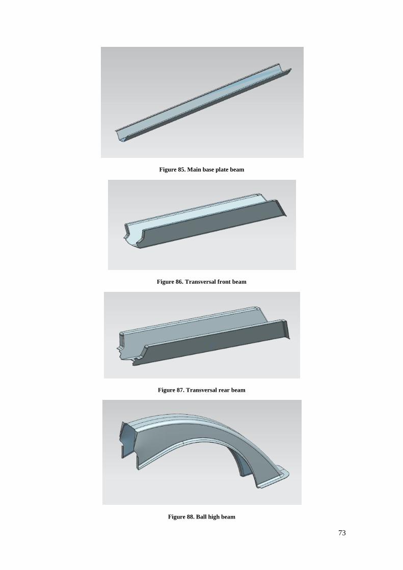
73
Figure 85. Main base plate beam
Figure 86. Transversal front beam
Figure 87. Transversal rear beam
Figure 88. Ball high beam
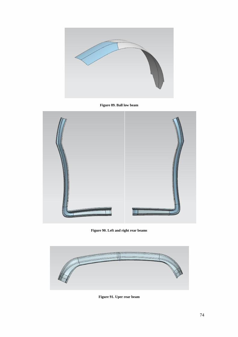
74
Figure 89. Ball low beam
Figure 90. Left and right rear beams
Figure 91. Uper rear beam

75
8.2 TABLES OF WEIGHT CALCULATIONS
Table 12. Complete table of weight calculations 1
Part quantity thickness (mm) weight (kg) added weight (kg)
Beams Front low 1 1,5 3,53 3,53
medium 1 1,5 4,23 4,23
high 1 1,5 1,79 1,79
Side Base 2 1,5 2,28 4,56
low 2 1,5 1,93 3,86
medium 2 1,5 3,9 7,8
high 2 1,5 5,09 10,18
Rear One part 2 1,5 3,31 6,62
Spline Main 1 1,5 5,79 5,79
side beam front 2 1,5 1,48 2,96
side beam rear 2 1,5 1,47 2,94
Ball low 1 1,5 1,48 1,48
high 1 1,5 3,29 3,29
Sheets floor 1 1,5 28,63 28,63
roof 1 1 16,2 16,2
front 1 1 7,58 7,58
side_front 2 1 3,45 6,9
side 2 1 7,66 15,32
side_down 2 1 2,78 5,56
rear 2 1 3 6
TOTAL 31 145,22

76
Table 13. Complete table of weight calculations 2
Part quantity thickness (mm) weight (kg) added weight (kg)
Beams Front low 1 1,5 3,53 3,53
medium 1 1,5 4,23 4,23
high 1 1,5 1,79 1,79
Side Base 2 1,5 2,28 4,56
low 2 1,5 1,93 3,86
medium 2 1,5 3,90 7,80
high 2 1,5 5,09 10,18
Rear One part 2 1,5 3,31 6,62
Spline Main 1 1,5 5,79 5,79
side beam front 2 1,5 1,48 2,96
side beam rear 2 1,5 1,47 2,94
Ball low 1 1,5 1,48 1,48
high 1 1,5 3,29 3,29
Sheets floor 1 1 19,09 19,09
roof 1 0,6 9,72 9,72
front 1 0,6 4,55 4,55
side_front 2 0,6 2,07 4,14
side 2 0,6 4,60 9,19
side_down 2 0,6 1,67 3,34
rear 2 0,6 1,80 3,60
TOTAL 31 112,65

77
8.3 FORMABILITY ANALYSIS
Figure 92. Thickness analysis on front sheet
Figure 93. Thickness analysis on rear sheet

78
Figure 94. Thickness analysis on side front sheet
Figure 95. Thickness analysis on side low sheet

79
Figure 96. Thickness analysis on floor sheet front 1
Figure 97. Thickness analysis on florr sheet front 2

80
Figure 98. Thickness analysis on floor sheet rear 1
Figure 99. Thickness analysis on floor sheet rear 2

81
8.4 FEM ANALYSIS
Figure 100. Deformation FEM analysis of side_medium beam
Figure 101. Deformation FEM analysis of front_medium beam

82
8.5 STEEL SPECIFICATIONS Steel for press hardening

83
Steel for conventional stamping
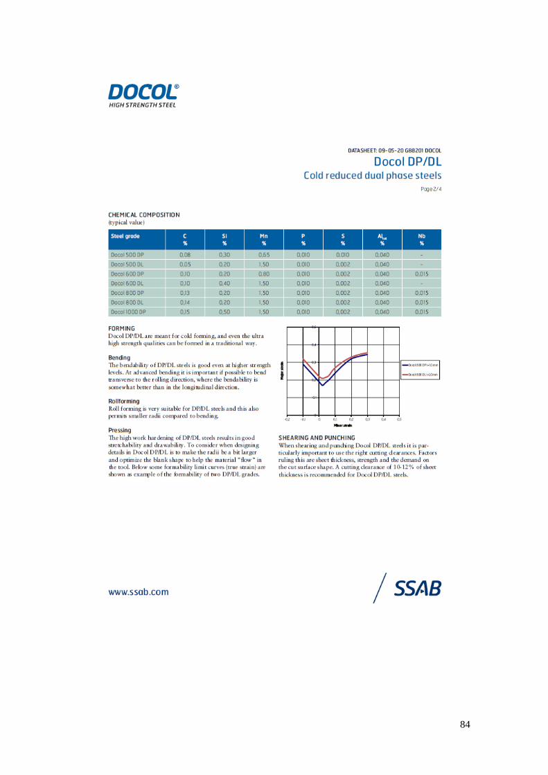
84
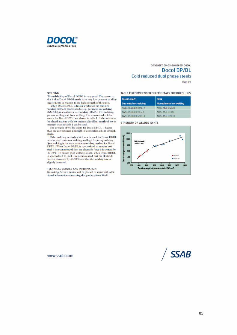
85