Friction Joints for Seismic Control of + Large Panel ... Journal/1980/Novem… · Types of joints...
24
Friction Joints for Seismic Control of + Large Panel Structures g Q I Avtar S. Pall* Senior Structural Engineer The SNC Group Montreal, Quebec Canada Cedric Marsh Professor Centre for Building Studies Concordia University Montreal, Quebec Paul Fazio Professor and Director Centre for Building Studies Concordia University Montreal, Quebec G round motions arising during earthquakes create oscillating lateral loads on buildings, thereby causing them to sway back and forth with an amplitude propor- tional to the fed-in energy. If the input energy can be controlled, and its major portion dissipated during building motion, the level of distress can be significantly re- duced. 'The research reported herein was conducted while Dr. Pall was Research Associate at Centre for Building Studies, Concordia University, Montreal, Quebec, In steel- framed buildings or cast-in-place concrete structures, reliance is placed on the ductility of the structure to dissipate energy while undergoing inelastic defor- mations. In large panel construc- tion, it is difficult to develop flexural ductility due to the lim- ited continuity in the vertical steel, and although in some Euro- pean systems the precast panels are jointed to give vertical con- tinuity, the suitability in general of this type of construction for seismic regions is often ques- tioned. The current seismic codes 38
Transcript of Friction Joints for Seismic Control of + Large Panel ... Journal/1980/Novem… · Types of joints...

Friction Joints forSeismic Control of
+ Large Panel Structuresg
Q
I
Avtar S. Pall*Senior Structural EngineerThe SNC GroupMontreal, QuebecCanada
Cedric MarshProfessorCentre for Building StudiesConcordia UniversityMontreal, Quebec
Paul FazioProfessor and DirectorCentre for Building StudiesConcordia UniversityMontreal, Quebec
G round motions arising duringearthquakes create oscillating
lateral loads on buildings, therebycausing them to sway back andforth with an amplitude propor-tional to the fed-in energy. If theinput energy can be controlled,and its major portion dissipatedduring building motion, the levelof distress can be significantly re-duced.
'The research reported herein was conducted whileDr. Pall was Research Associate at Centre forBuilding Studies, Concordia University, Montreal,Quebec,
In steel- framed buildings orcast-in-place concrete structures,reliance is placed on the ductilityof the structure to dissipate energywhile undergoing inelastic defor-mations. In large panel construc-tion, it is difficult to developflexural ductility due to the lim-ited continuity in the verticalsteel, and although in some Euro-pean systems the precast panelsare jointed to give vertical con-tinuity, the suitability in generalof this type of construction forseismic regions is often ques-tioned. The current seismic codes
38

are based on the premise of duc-tility, and impose severe penaltieson structures not possessing it,thereby acting against the adop-tion of panelized structures.
On the other hand, such struc-tures have been constructed inearthquake zones in the SovietUnion, Romania, Cuba, Japan, andtheir use is gradually spreading.''Inspection after severe earth-quakes has provided enough evi-dence to show that large panelbuildings, which have been de-signed for earthquake resistance,experience minimum distress.1,5While brick and framed buildingsfailed or were badly damaged, inpanelized buildings usually onlythe joints between the panels de-veloped cracks. Several full-scaleand large-scale models of pan-elized buildings, tested undersimulated earthquake loads, haveconfirmed these findings."
Large panel structures are thusseen to be capable of meeting therequirement of safety and damagecontrol, and the question arises asto how these structures, in whichthe development of flexural duc-tility is limited, could perform sowell. It now appears that the over-all energy dissipating capability ofthe structure is the key factor forits survival rather than just thepresence or absence of ductility.
Energy DissipationMechanism
During actual and simulated earth-quakes, the damage in large panelstructures is usually along the jointswith little damage in the panels them-selves. Cracking and slipping alongthese planes of weakness provides a
SynopsisConstruction with large pre-
cast concrete panels is widelyadopted throughout the world.However, in seismic regions,such structures are often viewedwith suspicion because of theserious problems posed by thetraditional jointing procedures.
A solution to these problemsis proposed in the form of fric-tion joints devised to dissipateenergy during severe seismicexcitations. By locating theseconnections in the vertical jointlines only, permanent deforma-tions and damage can beminimized.
Nonlinear time-history dy-namic analysis has been usedto study and to demonstratehow a building can be "tuned"so as to obtain optimum seismicresponse. The proposed jointsact, in effect, both as safetyvalves and structural dampers.
means for energy dissipation, compa-rable in effect to that due to inelasticyielding in ductile structures. Theseplanes of weakness are also responsi-ble for introducing a nonlinear be-havior to the overall building system,while the large panels themselves re-main in the elastic range. Thus, thejoints are in fact the only locationwhere energy can be dissipated and,hence, these very planes of weakness,properly harnessed, can be used tofurther improve the seismic response.The challenge, therefore, lies not onlyin providing joints of sufficientstrength but in maximizing theircapacity for energy dissipation.
PCI JOURNALLNovember•December 1980 39

verticalwall -to -wjoint
Fig. 1. Types of joints in large panel buildings.
Selection of Joint Location
In large panel construction, thereare basically three locations of joints:between floor panels, horizontallybetween wall panels, and verticallybetween wall panels (Fig. 1).
As the forces within floor dia-phragms are small, there is little prob-ability of slippage or energy dissipa-tion in the floor joints.
The horizontal joint between wallpanels is not a desirable location forenergy dissipation, because the nec-essary sliding movements will oc-cur only at the most highly loadedplanes, while the deformations will bepermanent as there are no correctiveelastic forces acting to straighten thebuilding (Fig. 2b). A pure rockingtype motion, i.e., opening and closingof joint as shown in Fig. 2c, in a typi-cal horizontal joint, even if post-ten-sioned, does not cause energy dissi-pation. 1O Furthermore, the concen-tration of vertical and lateral forces atthe corners of panels, associated withrocking motion, may cause failure ineither the connection or the panel_1.12
There remains the vertical jointbetween wall panels. This appears tobe by far the most suitable location ofa mechanism for energy dissipation.Unlike horizontal joints, the verticaljoints, after slippage to dissipateenergy, return to their original align-ment under the elastic action of thecantilevered shear walls, with little orno permanent deformations (Fig.2d).13 "5
Also, when the vertical joints slip,the overall building rigidity is re-duced, thereby lengthening the eflec-tive period of the building, which maybe beneficial. Even in extreme load-ing cases, the failure of a few connec-tions is not likely to threaten the over-all stability of the structure as theseare not the gravity load carrying joints.Other researchers have also con-eluded that vertical joint lines are themost logical choice for energy dissi-pation.'6 17
The vertical joints that may beutilized are the continuous joints be-tween end walls, the connectionsbetween corridor lintels and the right
HC

angle joints between wall panels in 1,T, L, C, and box sections aroundelevators or stair shafts.
Joint Design
For the vertical joints to function asan efficient means of energy dissipa-tion, they should possess
1. Elasto-plastic behavior;2. Stable hysteretic characteristics
over the number of cycles ex-pected in a severe earthquake;
3. An ability to accommodate rela-tively large deformations to dis-sipate sufficient energy; and
4. A capability to perform thesefunctions without permanentdamage.
In addition, the joints must satisfythe normal design functions and carrythe usual service loads, such as wind,within the elastic range. None of thejointing systems presently being usedmeets all the above requirements. Ofthe various alternatives studied, a me-chanical connection appears to be themost suitable.14 18
The Descon-Concordia system''uses bolted joints for horizontal wall-to-wall and slab-to-slab joints, butnot for the vertical joints, in thepanelized buildings first constructedfor "Operation Breakthrough" in theUnited States in 1973. Slotted holesare used to accommodate normal di-mensional tolerances. Static tests onthe prototype connections were con-ducted at the U.S. National Bureau ofStandards, and a typical result isshown in Fig. 3.24 2'
The anchorage was more than ade-quate to develop the joint strength.Dynamic cyclic tests under load re-versals were not conducted, as theconnections were designed as non-slipping friction type joints. However,the tests showed that with slottedholes the frictional movement couldgive the desired energy dissipationwithout causing inelastic yielding ofthe materials. A slipping bolted con-nection can, therefore, be engineeredto simulate the ideal "elasto-plastic"behavior, with a stable hystereticcharacter.
The connection chosen consists of
a) No shear slip
b) Horizontal shear slip c) Rocking
d) Vertical shear slip
Fig. 2. Modes of deformation of structures for various conditions.
PCI JOURNAL/November-December 1980 41

200
1610]
z
100
0
50
0 2 4 6 8 10 12
DISPLACEMENT , mm
Fig. 3. Load -deformation response of a "Descon-Concordia" bolted joint.
steel plates or sections, with slottedholes, connected by high strengthbolts to steel inserts anchored in theconcrete panels. The length of' the slotaccommodates the normal fabricationand erection tolerances with an addi-tional clearance on either side of thebolt to allow the desired slip.
Fig. 4 shows the details of the Lim-ited Slip Bolted (LSB) joints for someof the vertical wall-to-wall connec-tions. The connecting plate is boltedin position during erection but is fi-nally welded on one side to preventthe rotation of the plate when slippingOccurs.
The joints are designed not to slipunder loads in service, but are ex-pected to slip during severe seismicexcitations and so they will not begrouted, but sealed by other appropri-ate means.
Attention will need to be paid to thedetails of floor joints and other fin-ishes along the slip planes to accom-modate the differential movement ofthe walls.
Testing of the Joints
Static and dynamic cyclic tests wereconducted on several types of con-nection, having different faying sur-face treatments, to evaluate their basicdesign properties. Load-deformationcurves and hysteresis loops, using12.7 mm (Vs in.) diameter highstrength bolts (ASTNI-A325), areshown in Figs. 5 and 6, respectively.
A predictable and repeatable load isthe most important requirement to en-sure a predictable response of thestructure. Although metalized surfacesshowed the highest static slip coeffi-cient and energy dissipation, they arenot desirable as the performance is farfrom predictable. All the externallyapplied coatings on metal surfaceswhich were tested were eliminated onthis basis.
The best behavior is shown bybrake lining pads inserted betweensteel plates with mill scale surfaces.This joint exhibits a constant, repeat-
42

weld after erection
conneCtinq nrect. washersplate
insert anchors
joint INSERT
ELEVATION
connecting platebolts (ASTM A3251insert
0 o0 0
CONNECTING PLATEI panel (nuts welded to
insertSECTION
a) Simple wall - to- wall joint
wall panels
wall pone
SECTION SECTION
b) Corner wall - to- wall joints
Fig. 4. Typical details of Limited Slip Bolted (LSB) joints. Simple wall-to-wall joint(top); corner wall-to-wall joints (bottom).
PCI JOURNALjNovember-December 1980 43

I. Mill scale Expected shear2. Grit blasted failure of bolt f`^•
120 3. Zinc-rich paint4. Metalized
Z 100 5. Sand blasted ,6 Brake lining pods
6
80..^,
4- ^E G_^^r arr. ^^r^ r
6....................... f
3
v- •-•_._ _._._._._.- _.
20
0 2 4 6 8 10 12
DISPLACEMENT, mm
Fig. 5. Load-deformation response of Limited Slip Bolted (LSB) joints.
able slip load and nearly "elasto-plas-tic" behavior, with negligible degra-dation. Sand blasted steel surfaces arethe second choice.
The load-de formation relationshipof the complete joint is elastic tip tothe point of slipping, after which it is"plastic." Should the bolt reach theend of the slot it becomes elastic againup to the load causing failure in thebolt. The anchorage into the concretepanel is assumed to remain elastic.
Earlier tests 22 indicate that relaxa-tion in bolt tension over a period of 20years is not more than 8 percent.Using precompressed heavy dutybreak lining pads, the additional lossin bolt tension has been shown to re-main unchanged over a period of oneyear. Tests to determine the slip loadafter longer periods are being con-ducted.
Seismic Analysis
A panelized building assembledusing LSB joints will behave in anonlinear manner when subjected toseismic action severe enough to cause
the joints to slip. To investigate theinfluence of these joints on the seis-mic response, the typical apartmentbuilding plan shown in Fig. 7 waschosen.
The dimensions are representativeof a popular crosswall system in largepanel construction. The two halves ofeach end wall are coupled together byusing two LSB joints per story heightwhile interior crosswalls are assumedto be coupled at the corridor beamwith a single LSB joint. The studieswere made for the exterior end walls,which are the most heavily loaded.
Nonlinear time-history dynamicanalysis was carried out using thecomputer program "Drain-2D, "23
which was modified to incorporate thebehavior of LSB joints. The earth-quake record of El Centro 1940,north-south component, was used as itis reasonably symmetric. It is knownthat different earthquake records,even though of the same intensity,may give widely varying structural re-sponses, and values obtained using asingle record may not be conclusive.
The analysis was conducted for aduration of 7 seconds, which includes
44

c) Inorganic Zinc-Rich point
40
i20
0 2a(MM)6
20
40
To 108 6 4 2
Ia) Mill scale b) Sand blasted
Ed
e) Brake Lining Pads f) Polyethylene Coating
Fig. 6. Hysteresis loops of Limited Slip Bolted (LSB) joints.
PCI JOURNALNovember- December 1980 45
7.3m 7.3 7,3 7.3 7.3 7.3m
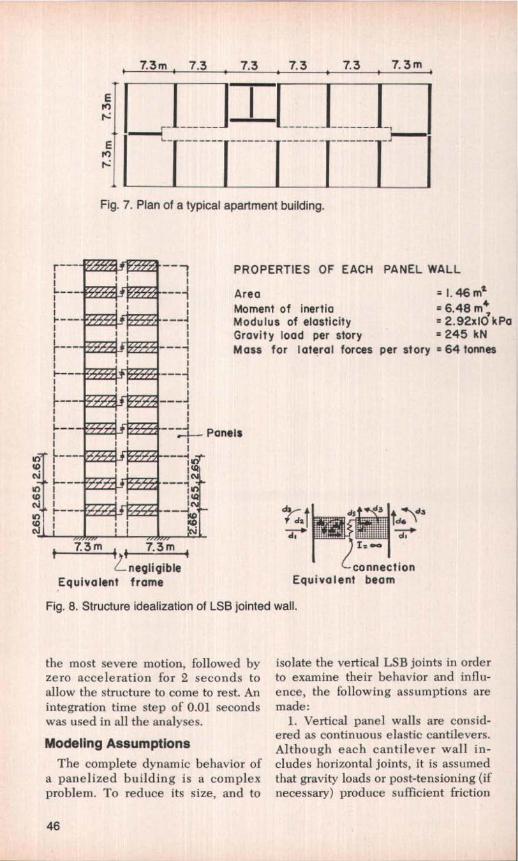
ro It I f -------Fig. 7. Plan of a typical apartment building.
PROPERTIES OF EACH PANEL WALL
--- --i Area = 1.46 mxI Moment of inertia = 6.48 m4
^--- -- Modulus of elasticity = 2.92x10 kPa' Gravity load per story = 245 kN
-- --- Mass for lateral forces per story = 64 tonnes
' I
---,i_-_ PanelsI--- ---i
tV I NtD 1 i i
'ds
d1 ^diKvcif 4V
'° ciEd^ i ";::ES3;:E:
7.3m,
L negligible connectionEquivalent frame Equivalent beam
Fig. 8. Structure idealization of LSB jointed wall.
the most severe motion, followed byzero acceleration for 2 seconds toallow the stricture to come to rest. Anintegration time step of 0.01 secondswas used in all the analyses.
Modeling Assumptions
The complete dynamic behavior ofa panelized building is a complexproblem. To reduce its size, and to
isolate the vertical LSB joints in orderto examine their behavior and influ-ence, the following assumptions aremade:
1. Vertical panel walls are consid-ered as continuous elastic cantilevers.Although each cantilever wall in-cludes horizontal joints, it is assumedthat gravity loads or post-tensioning (iinecessary) produce sufficient friction
46

to prevent any shear slip or rocking,and nonlinear behavior of the struc-ture is limited to the LSB joints.
2. The floor diaphragms are suffi-ciently rigid in their own planes todistribute the lateral forces betweenthe walls in proportion to their stiff-nesses. This is generally true except,perhaps, for certain proportions of lowrise buildings.14
3. Mass and stiffness dependenttype viscous damping correspondingto 5 percent of critical is assumed forelastic panel walls. Energy dissipationdue to hysteretic behavior of LSBjoint itself is accounted for in thecomputer program.
4. The foundations are rigid andsoil-structure interaction is ignored.
The above assumptions, althoughnot completely true, are reasonableenough to concentrate the study onthe role of LSB joints.
The stresses and forces computed inthis study are only for comparisonpurposes and are not intended to bedesign values.
Structural IdealizationThe coupled walls are idealized as
an equivalent wide column frameshown in Fig. 8. Effects of flexural,axial, and shear deformations aretaken into account. The two LSBjoints in each story height are lumpedat each floor level and modeled as
fictit ious axial elements yielding intension and compression, using amodified subroutine of a truss ele-ment. The full load-deformation re-lationship for the joint, shown in Fig.9, i.e., elastic-plastic-elastic-failure, isrepresented in the subroutine.
Optimization ofSeismic Response
For any earthquake motion, the re-sponse of a panelized structure is de-termined by the amount of energy fedin and the energy dissipated. The op-timization of seismic response, there-fore, consists of minimizing the differ-ence between the input energy andthe energy dissipated.
The energy input is basically de-pendent upon the mass and the natu-ral frequency of the structure. Thelatter is influenced by the slip loadand the stiffness of the joints. Withstrong joints between two walls,creating a monolith, the natural periodof vibration will be t„ as shown inFig. 10. Isolated walls will have alonger period, tr. The introduction ofLSB joints will result in a period, t3,intermediate between t, and tz whichwill vary with the slip load and withthe amplitude of the oscillation.
The energy dissipated in a verticaljoint is proportional to the product of
P KStage 4 , failureStage 3, bearing Ko K 0
Stage 2, slippingStage 1, elastic
slip length A I(2 Ki
STIFFNESS OF EACH CONNECTIONStage I (Ka) = 64x104kN/mStage 2 (K i ) = 0
K o Stage 3 (Ks) = 32x10^kN/mT (Two connections used for
each story )
a) Load – deformation b) Hysteretic behavior
Fig. 9. Idealized behavior of LSB joint.
PCI JOURNALJNovember-December 1980 47

r''2 /` t2
13 f ^ f3o tabWO
HJ timea_
VLSB jointed walls
Isolated wallsElastically jointed walls -- — —
Fig. 10. Oscillation of various types of walls.
wall yieldingat base
IPy
ZIKW Ps
•Nigh slip load' Optimum slip load
I I/,.. !Low slip load
K 1 for coupledwall
Ay A d Ay a
a) Isolated Walls b) LSB joint c) LSB jointed wall
Fig. 11. Effect of joint slip load on load-deformation response of walls.
SI
Kw
a) High slip load b) Low slip load c) optimum slip load
Fig. 12. Effect of joint slip load on hysteretic behavior of coupled walls.
48

the slip load and the slip travel duringeach excursion. The effect of the slipload on the deformation of a singlestory wall is conceptually shown inFigs. 11 and 12. For a very high slipload, the energy dissipation will bezero, as there will be no slip in thejoint. If the slip load is very low, theamount of energy dissipated willagain be negligible. Evidently, theslip load has to be of an intermediatevalue to maximize energy dissipation.This is clearly seen in Fig. 12c.
For a single excursion of a symmet-ric double shear wall, with a specifiedlimiting stress, the maximum energythat can be dissipated by friction inthe joint in a quarter cycle is equal tothe elastic energy in the walls atmaximum amplitude. This is equiva-lent to critical damping. However, inan actual earthquake, the amplitudevaries, with only a few excursionscausing the limited stress. Theaverage damping will thus he muchless than critical (small amplitudes areelastic), The optimum slip load willvary with the earthquake intensity,and, to some extent, with the type ofearthquake spectrum. The value ofthis optimum is found by direct dy-namic analysis.
Softening of the structure, dueto slipping of the joints, can mean aninvitation to either higher or low-er seismic forces, depending uponwhether the natural frequency of thebuilding is moved towards, or awayfrom, the dominant frequency of theground motion. The beneficial effectsof energy dissipation must thereforehe combined with the positive ornegative effects of the prolongedperiod of vibration.
Parametric StudiesThe following parametric studies
were carried out to determine the ef-feet of each on the seismic response.The values given for the joints are
those for the sum of the joints in eachfloor:
1. joint stiffness: (128 to 256 x 104kN/m);
2. Slot Iength: (30 to 40 mni for20-mm bolt);
3. Slip load of the joint per storyheight: (0, 160, 320, 640, 2560kN);
4. Building height: (5, 10, 15, 20stories);
5. Seismic intensity: (0.15, 0.25,0.33, 0.5 of gravity).
It was observed that:
(a) The variation in the initial stiff-ness of the joint assembly, within thepractical range of such joints, does notcause appreciable change in the re-sponse.
(b) The restriction of the slot lengthin the connecting plate does not im-prove the response of the structure,but, on the contrary, could result inpermanent damage to the joint and thepanels due to the sudden increase inforces caused by the closing of' thejoint and by the shear failure of thebolt. A sufficient length must be pro-vided to accommodate erection toler-ances plus the total movement up tothe limiting stress in the walls them-selves,
(c) For a given earthquake intensityand building geometry, the slip loadof the joint is the variable which mostinfluences the seismic response. Byvarying the slip load, it is possible to"tune" the response of the structure toan optimum value. The influence ofthe slip load on the maximum normalstresses at the base and on themaximum deflection at the top isshown in Figs. 13 and 14. Slip loads of0 to 2560 kN represented unjointedwalls and non-slipping elastic joints,respectively.
In general, the slip load whichgives the minimum normal stress atthe base also gives the minimumdeflection, story shear and overturn-
PCI JOURNAL/November-December 1980 49

3 LEGEND
0 21\
a ^.a: I
I
20 STORY------ 15 STORY
10 STORY---- 5 STORY
0 320 620 960 1280 1600 1920 2240 2560SLIP LOAD , kN
a) Ratio of stress of jointed wall to elasticallyjointed wall.
0 320 620 960 1280 1600 192022402560SLIP LOAD, kN
b) Ratio of stress in jointed wall to isolatedwalls
Fig. 13. Influence of joint slip load on normal stresses in walls.
01I—a
ing moment. The optimum slip loadvalue varies directly with the seismicintensity.
(d) The response of 5- and 10-storywalls (where the period is less than0.5 seconds), is distinctly differentfrom that of 15- and 20-story walls(where the period is greater than 0.5seconds). In 5- and 10-story walls, thebeneficial effect of energy dissipation
is countered by the negative effect ofthe increased seismic force caused bymoving the natural frequency towardsthe dominant frequency of the earth-quake, while for 15- and 20-storywalls, the benefit of energy dissipa-tion is added to that of reduced seis-mic force due to the softening of thestructure. The limiting buildingperiod depends upon the dominant
50

4.5
3
21o ^F-a II=
LEGEND
20 STORY---- 15 STORY
10 STORY----- 5 STORY
0 320 620 960 1280 1600 1920 2240 2560SLIP LOAD, kN
a) Ratio of deflection of jointed wall t oelastically jointed wall.
2
0H ^4nr
0 320 620 960 1280 1600 1920 2240 2560SLIP LOAD, kN
b) Ratio of top deflection of jointed wall toisolated walls
Fig. 14. Influence of joint slip load on wall deflection.
frequency content of the earthquakemotion.
An artificial record, generated at theMassachusetts Institute of Technol-ogy2s to match the Newmark-Blume-Kapur response spectrum, was alsoused. It was observed that althoughthe response differed widely from thatof the El Centro record, the value ofthe optimum slip load for a given
seismic intensity is almost indepen-dent of the time history of the earth-quake motion.
Discussion of Results
The effectiveness of LSB joints inimproving the seismic response ofpanelized buildings is seen in the
PCI JOURNAUNovember-December 1980 51

10 20 LEGEND_ jointed walls
J
8 1 I 16 ,j;
LSB
—€solated walls
j `;
^Lii 6 Li 1 jointed
6 `1 12 ,^ walls
4 t0 $U 52 4
0 I 0 1 2 3 4 5x10
s 0 0 1 2 3 4 5x10
SHEAR, kN SHEAR, kN
Fig. 15. Shear envelope (0.33g).
201 LEGEND_LSB jointed walls
16 Isolated walls
Elastically jointed12 walls
8
4
iu
8
6
4
2
0 10203040 00 10 20304
STRESS, MPa STRESS, MPa
Fig. 16. Normal stresses (0.33g).
comparisons between the results ob-tained for isolated walls (zero slipload), for walls with strong elasticjoints (slip load = 2560 kN), and forwalls with the optimum slip load.
Story Shears
In the case of 5- and 10-story walls,the reduction in base shear is about 30and 25 percent when compared to iso-
lated walls, while little benefit is de-rived when compared to walls withstrong elastic joints.
For both 15- and 20-story walls, thereductions in the story shears are 35and 65 percent when compared toisolated and elastically jointed walls,respectively. The lower story shearreduces both the stresses in the hori-zontal joints and the building acceler-
52

E
BJW
w 6J
Q40JU-
2
C
LEGEND_S B jointed walls
Isolated walls
Elastically joinledwalls
A, mm D, mm
Fig. 17. Deflection envelope (0.33g).
10 20 LEGEND--LSB joinled wails
8 16-\^^ `, Elastically jointed
6 ^ 12 '. walls
4 % 8--640 1520 160 I —2160
r r
2 i 4 /
00 4 8 12 16xl0 0 0 48 12 16 20x10
FORCE, kN FORCE , kN
Fig. 18. Forces in joints (0.33g).
ations. Typical story shears for 10- and20-story walls for a seismic intensityofO.33g are shown in Fig. 15.
Normal Stresses in PanelsFor 5- and 10-story walls, the stress
with LSB joints is almost the same aswith strong elastic joints, but it is ap-proximately 35 percent of that in iso-lated walls,
In both 15- and 20-story walls, thestresses with LSB joints are about 40and 65 percent of those for strongelastic joints and isolated walls, re-spectively. Normal stresses for 10- and20-story walls for a seismic intensityof 0.33g are shown in Fig. 16. Theeffectiveness of LSB joints in reduc-ing the normal stress is shown in Fig.19.
PCI JOURNAL/November-December 1980 53

20 q LEGEND
[LSB jointed wall I
Elastically jointed walls
15 A. ILSS jointed wall ]-,Ratio of max. '.^ Isolated wallsW
FE deflections _...0 - `..- Ratio of max.~ "'^ `^ deflections(.1)a 10 '
mM Ratio of max. I
--bending stresses ------ -rl /'I
z 5/
0 0.25 0.5 0.75 1.0RESPONSE, RATIO
Fig. 19. Relative response of LSB jointed wall for different wall heights (0.33g).
DeflectionsThe deflections of LSB jointed
walls of 5- and 10-story height aresimilar to those for elastically jointedwalls, but are about 30 percent ofthose for the isolated walls.
For 15- and 20-story walls, the de-flections are approximately 50 and 70percent of those for isolated walls andstrong elastic joints, respectively.Typical deflection envelopes for 10-and 20-story walls for a seismic inten-sity of 0.33g are shown in Fig. 17. Theeffectiveness of LSB jointed wall inreducing the building deflections isshown in Fig. 19.
Forces on the ConnectionsThe distribution of forces in the
elastic joints and the LSB joints isshown in Fig. 18. The force in theelastic joints varies over the buildingheight and increases with an increas-ing severity of earthquake. In the case
of LSB joints, as the connections slip,redistribution of forces takes placeuntil they become almost uniformthroughout the height.
One of the advantages of the slip-ping joints is, therefore, to provide alimit to the load, which is a predeter-mined value independent of seismicintensity. It also allows the full capac-ity of all the connections to beutilized. Since the force level in LSBjoints was far less than that in non-slipping joints, no damage would havebeen caused to the joint anchorages orthe panels.
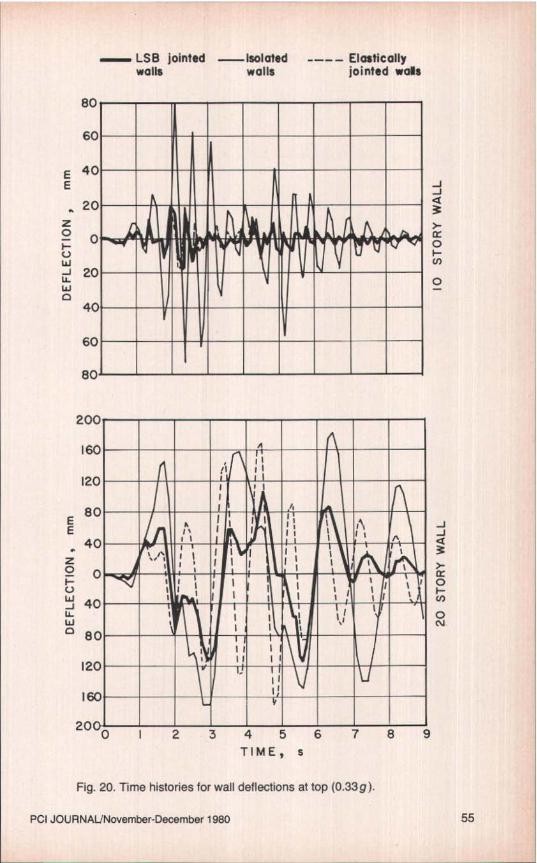
Time HistoriesTypical time histories for the top-
most story of 10- and 20-story walls fora seismic intensity of 0.33g are shownin Fig. 20. For the 10-story wall, thepeak amplitude of the LSB jointedwall is far less than that for isolatedwall but is almost the same as that of
54
200
160
120
E80
E40
a 0FUUiJ 40W° 80
120
160
2oa
_'I__ii_ri
_ _ ii ii111 Il .__1MIItM1
JJ
ir0
H0CV
LSB jointed Isolated —__ Elasticallywalls walls jointed wals
EE
z0UWJU_Wd
JJ
>-
0H
O
0 I 2 3 4 5 6 7 8 9TIME, s
Fig. 20. Time histories for wall deflections at top (0.33g).
PCI JOURNAL/Novernber-December 1980 55
TuIi_NU_I
zI-2
0(I).W.U
0L
E eEI-20
z_
I-I-2W2W
Ja
2I
Z0
zO
Wo ^I
O1, 1
0 I 2 3 4 5 6 7 8
9TIME, s
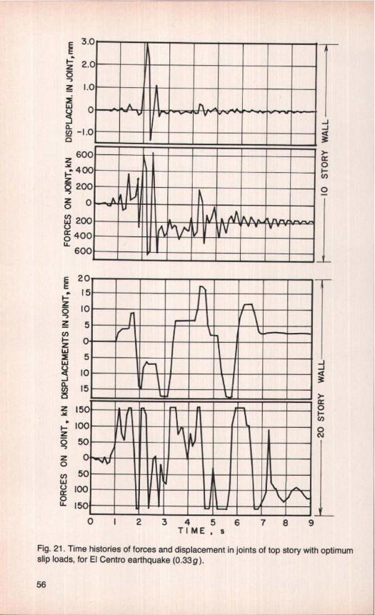
Fig. 21. Time histories of forces and displacement in joints of top story with optimumslip loads, for El Centro earthquake (0.33g).
—JJa9>-a:0
O
—J—J
3}0U)
0N
56

the elastically jointed wall. However,since the effective period of vibrationof the LSB jointed wall is longer thanthe elastically jointed wall, the accel-erations experienced by this wall areless.
The effectiveness of the hystereticdamping of the LSB jointed wall ismore clearly seen in the case of the20-story wall. The amplitude of vi-brations and accelerations are consid-erably less than for both elasticallyjointed and isolated walls.
It was observed that the effectiveperiod of vibration of LSB jointedwalls changes with the amplitude ofvibration, i.e., with the increasing se-verity of the earthquake, resonance ofthe structure is thus more difficult toestablish.
Time histories of forces and dis-placements in LSB joints of the topstory are shown in Fig. 21. It is seenthat, under the elastic action of thecantilever walls, all the connectionsreturn almost to their original positionand are ready to face future earth-quakes with nearly the same effi-ciency. There may be some residualforces in the connections at the end ofthe earthquake, but that does not af-f'ect their future performance.
Equivalent Ductility andHysteretic Damping
Nonlinear behavior has been quan-tified by the value of an equivalentductility defined in various ways, butusually viewed as the ratio of thelimiting deflection to that at the onsetof inelasticity. For the friction joints ofthe type described, the ratio of thedeflection at some limiting stress inthe concrete to that at the first slip of ajoint, for the optimum energy dissipa-tion at peak amplitude, is approxi-mately 6. During an earthquake, theamplitude varies, and to obtain theoptimum energy dissipation for the setof cycles experienced, a lower valueof the slip load is required, with a re-
suiting higher value of the above ratio.No direct means is available to
apply the value to obtain an equiva-lent viscous damping, other than bythe complete analysis of the structuredamped viscously and damped byfriction. The comparison obtained isvalid only for the particular casestudied at the particular earthquakeintensity assumed.
In the present studies, with the op-timum slip load for a given intensityobtained from the dynamic analysis,the behavior is equivalent to that re-suiting from a viscous damping of ap-proximately 20 percent.
Practical ApplicationThe adoption of this device for
seismic control will require an ar-rangement of walls and floors suchthat independent movement is possi-ble at the slip planes. Pipes, ducts,finishes and seals which might bebroken if they cross these planes musthe appropriately treated.
To provide some perspective on therelative value of the slip load, a sim-ple analysis is given in the appendix.
Conclusions
The limited slip bolted joint hasbeen developed to meet the require-ments of an efficient energy dissipat-ing connection with elasto-plastic be-havior and stable hysteretic charac-teristics.
That it be the vertical lines of con-nections in which LSB joints are in-corporated is of particular importanceas:
1. The level of energy dissipation ishigher than with horizontal jointssince the process acts over the fullheight.
2. The joint strength can be uni-form and all joints can contribute.
3. The building is softened withoutlosing its elasticity and resilience and
PCI JOURNAUNovember-December 1980 57

recovers with little or no permanentset.
4, The joints act as structural damp-ers to control the amplitude, and assafety valves to limit the load exerted.
5. The amplitude of vibrations andaccelerations are considerably re-duced, hence secondary and archi-tectural damage is minimized.
6. The building can be "tuned" foroptimum response without resortingto other expensive devices like hy-draulic systems or added masses; this"tuning" represents matching the slipload to the anticipated maximumearthquake intensity to give minimumacceleration in the building.
7. There is no yielding of materialsinvolved in the process of energy dis-sipation, hence no damage is caused.
8. The joints lose little or no ten-
sion, and remain without adjustmentready to face the next earthquake withthe same efficiency.
The concept of energy dissipationthrough friction in slipping joints canbe easily extended to framed build-ings clad with precast concrete curtainwalls or infill panels. In this case,either horizontal or vertical joints maybe allowed to slip as they carry nogravity loads.
LSB joints may also be used in tallcast-in-place shear walls to increasethe flexibility of the otherwise rigidwalls and to dissipate energy, result-ing in overall improved seismic re-sponse. Since large amounts of seis-mic energy can he dissipated in fric-tion, ductility demand, which is as-sociated with structural and secondarydamage, can be considerably reduced.
REFERENCES1. Djabua, S. A., Chachara, T. N_, Aba-
shidze, C_ G., Djishkariani, N. M., andKemoklidze, C. S., "Research onSeismic Resistance of Large PanelApartment Buildings," Sixth WorldConference in Earthquake Engineer-ing, New Delhi, India, 1977, pp. 5-299to 303.
2. Ikeda, A., Yamada, T., Kwamuici, S.,and Fuiji, S., "State of Art of PrecastConcrete Techniques in Japan," Pro-ceedings, Workshop on EarthquakeResistant Reinforced Concrete Build-ing Construction, University of Cali-fornia, Berkeley, 1977.
3. Hawkins, N. M., "State-of-the-Art Re-port on Seismic Resistance of Pre-stressed and Precast Concrete Stnic-hires—Part 2," PCI JOURNAL, V. 23,No. 1, January-February 1978, pp.40-58.
4. Becker, J. M., and Lorente, C., "Seis-mic Design of Precast Concrete PanelBuildings," Earthquake Resistant Re-inforced Concrete Building Construe-
tion, University of California, Berke-ley, July, 1977.
5. Fintel, M., "Performance of PrecastConcrete Structures During RomanianEarthquake of March 4, 1977," PCIJOURNAL, V. 22, No, 2, March-April1977, pp. 10-15.
6. Diaconu, D., et al., "Seismic Responseof Great Panel Structures with 10Stories," Fifth World Conference inEarthquake Engineering, Rome, Italy,1973, pp. 2706-2716.
7. Polyakov, S. V., et al., "Investigationsinto Earthquake Resistance of LargePanel Buildings," Fourth World Con-ference in Earthquake Engineering,Santiago, Chile, 1969, pp. B-1, 165-180.
8. Barkov, Y. B., Glina, Y. V., 'Theoreti-cal and Experimental Investigations ofPrecast and Monolithic FramelessBuildings on Large Scale ReinforcedConcrete Models," Fifth World Con-ference in Earthquake Engineering,Rome, Italy, 1973, pp. 2731-2734.
58
9. Velkov, M. P., "Earthquake ResistantDesign of Twenty-One Story Prefabri-cated Large Panel Building," SixthWorld Conlerence in Earthquake En-gineering, New Delhi, India, pp, 5-239-244.
10. Powell, G., Schricker, V., "DuctilityDemands on Joints in Large PanelStructures," Annual Convention,American Society of Civil Engineers,San Francisco, California, October,1977, Reprint 3022.
11. Becker, J. M., Lorente, C., "The Seis-mic Response of Simple Precast Con-crete Panel Walls," Second U.S. Na-tional Conference on Earthquake En-gineering, Stanford, Connecticut, Au-gust, 1979.
12. Polyakov, S., Design of EarthquakeResistant Structures, First Edition,MIR Publishers, Moscow, SovietUnion, 1974.
13. Pall, A. S., Marsh, C., "Energy Dissi-pation in Panelized Buildings UsingLimited Slip Bolted Joints," Proceed-ings, AICAP-CEB Conference, V. III,Rome, Italy, May, 1979, pp. 27-34.
14. Pall, A. S., "Limited Slip BoltedJoints-A Device to Control the Seis-mic Response of Large Panel Struc-tures," PhD Thesis, Center for Build-ing Studies, Concordia University,Montreal, Canada, September, 1979.
15. Pall, A. S., and Marsh, C., "SeismicResponse of Large Panel StructuresUsing Limited Slip Bolted Joints,"Proceedings, Third Canadian Confer-ence on Earthquake Engineering,Montreal, Canada, June, 1979, pp.899-916.
16. Mueller, P., and Becker, J. M., "Seis-mic Characteristics of Composite Pre-cast Walls," Proceedings, Third Cana-dian Conference on Earthquake En-gineering, Montreal, Canada, June,1979, pp. 1169-1199.
17. Paulay, T., "Earthquake ResistantStructural Walls," Proceedings, Earth-quake Resistant Reinforced ConcreteBuilding Construction, University ofCalifornia, Berkeley, 1977, pp. 1339-1365.
18. Pall, A. S., Marsh, C., and Fazio, P.,"Limited Slip Bolted Joints for LargePanel Concrete Structures," Proceed-ings, International Symposium Be-havior of Building Systems andBuilding Components, VanderbiltUniversity, Nashville, Tennessee,March, 1979, pp. 385-404.
19, Dawson, W. F., and Shemie, M.,"Bolted Connections as a Substitutefor on Site Welding and Wet Joints inPrecast Concrete," Proceedings,Canadian Structural Concrete Confer-ence, Ottawa, Canada, 1977, pp. 269-289.
20. Shemie, M., "Bolted Connections inLarge Panel System Buildings," PC[JOURNAL, V. 18, No. 1, January-February 1973, pp. 27-33.
21. Cattaneo, L. E., and Yoke, F. Y.,"Structural Tests of Mechanical Con-nections for Concrete Panels," Na-tional Bureau of Standards, Preparedfor the Office of Research and Tech-nology, Department of Housing andUrban Development, Washington,D.C., November, 1972.
22. Fisher, J. W., and Struik, J. H. A.,Guide to Design Criteria for Boltedand Riveted Joints, John Wiley andSons, New York, 1974.
23. Kannan, A. E., Powell, G. H.,"Drain-2D, A General Purpose Com-puter Program for Dynamic Analysisof Inelastic Plane Structures," Collegeof Engineering, University of Califor-nia, Berkeley, 1973.
24. Unemori, A. L., Roesset, J. M., andBecker, J. M., "Effects of Inplane FloorSlab Flexibility on Response of CrossWall Building System," Paper pre-pared for Symposium on MathematicalModeling of Reinforced ConcreteStructures, ACE Committee 442-Re-sponse of Buildings to Lateral Forces,1978.
25. Mueller, P. and Becker, J. M., `Seis-mic Response of Large Panel PrecastConcrete Buildings," Seminar on Ad-vanced Design Concepts in PrecastPrestressed Concrete, PCI AnnualConvention, Dallas, Texas, October1979.
PCI JOURNAL/November-December 1980 59

APPENDIX A-OPTIMUM SLIP LOAD
Consider the double cantilever wall of Fig. Al subjected to a triangular loaddistribution representing seismic load.
Along the joint between the walls is a uniform shear flux of q per unit length.The slip between the walls, multiplied by the shear flux, q, is the work done
against friction in the joints. This is given by:
n E x3 Sqx QhE 11 wh 2 8 qh
Uf Q Jo
J hI
, Eb 2 c 3x h Ebt dx dx =
E 20 bet 3 bt
(Al)
If the maximum stress is limited to a u , then:
wh' _ 2qhb e t bt (A2)
Using this condition, the maximum energy dissipation will occur when:
bt = 0176o- (A3)
This leads to the following relationships at the optimum condition:
slip load per floor= 0.176bt o-„In (A4)
where n is the number of floors.
Energy dissipated in each quarter cycle = 0.048 a VIE (A5)
Elastic energy at peak amplitude = 0.052 or. VIE (A6)
where V = volume of concrete in one wall = bth
Value of w at first slip = 0.47 o b 2 tlh (A7)
Maximum value ofw = 1.35 a b 2 the (A8)
Stress at first slip = 0.235 a- u(A9)
Deflection at first slip = 0.065 cl-„ 11 2 lEb (A10)
Deflection at limit = 0.39 o• ,^ h 2 IEb (All)
The limiting stress, Q,, may be governed by cracking, the yield in the steel,or some other appropriate limit that can be represented by o.
Consider the end wall of the building plan in Fig. 7 for a 15-story building.The following values apply:
b= 7.3m,t= 200mm,n= 15, andletv„= 10MPa
Required slip load per floor= 0.176 x 7.3 x 0.2 x 10,000115= 170 kN
60

W
t;'z^rf
rb b
STRESS DUE TO w
STRESS DUE TO q mob°TOTAL STRESS
o.^
Fig. A1. Stress in double shear wall.
Note that this value is dictated entirely by the proportions of the wall and thelimiting stress chosen, This value of the slip load would maximize energy dis-sipation far those cycles in which the peak stress is o-,.
This may not minimize accelerations for all earthquake intensities, but it willbe the optimum that can be achieved without exceeding o, and will ensurethat as much energy as possible has been dissipated by the friction joint beforethe walls sutler permanent damage. An appropriate value of limiting stress, (Y5,
can be obtained by equating the sum of Eqs. (A5) and (A6), i.e., 0,1 o•u VIE, tothe peak energy input for a given earthquake intensity.
NOTE: 1 ft = 0.305 m;1 in. = 25.4 mm;1 kip = 4.448 kN;1 psi = 0.006895 MPa;1 kiplft = 14.594 kN/m.
Discussion of this paper is invited.Please forward your comments toPC! Headquarters by July 1, 1981
AcknowledgmentThe research reported herein was sup-
ported by the Natural Science and En-gineering Research Council of Canada, andLa Formation des Chercheurs et d'ActionConcertee du Qu@bec.
The cooperation of researchers at theMassachusetts Institute of Technology(and particularly the help extended by Dr.James M. Becker) is also gratefully ac-knowledged.
PCI JOURNAL/November-December 1980 61