FRESH SPNTCATLYST CATLYST - Google Compute Engine
16
Transcript of FRESH SPNTCATLYST CATLYST - Google Compute Engine

July 5, 1966 M. F. NATHAN Re- 26,060 ALKYLATION OF HYDROCARBONS
Original Filed June 5, 1959 4 Sheets-Sheet 1
52
CC 0 zn u) u u: n. 2 O U
FRESH SPENT CATALYST CATALYST INVENTOR.
MARVIN F. NATHAN
BY ?. (7/ FM ATTORNEY
Z n. LL ( CC
E O ‘E.
July 5, 1966 M. F. NATHAN Re- 25,060 ALKYLATI ON OF HYDROGARBONS
Zriginal Filed June 55, 1959 4 Sheets-Sheet 2
90
COMPRESSOR
NEUTRALIZATION h- PARAFFIN
ALKYLATE
F‘G. 2 SPENT CAEl'??ggT CATALYST
INVENTOR. MARVIN F. NATHAN
BY ZZZ/M ATTORNEY
l3 ISOPARAFFiN


United States Patent 0 1
26,060 ALKYLATION 0F HYDROCARBONS
Marvin F. Nathan, Westport, Conn., assignor to Pullman Incorporated, a corporation of Delaware
Original No. 3,187,066, dated June 1, 1965, Ser. No. 817,798, June 3, 1959. Application for reissue July 9, 1965, Ser. No. 471,793
22 Claims. (Cl. 260—683.62) _Matter enclosed in heavy brackets [ ] appears in the
original patent but forms no part of this reissue speci? cation; matter printed in italics indicates the additions made by reissue.
This invention relates to an improved condensation process and more particularly to the alkylation of iso paraf?ns with ole?ns in the pressure of an alkylation cata lyst to produce hydrocarbon compounds boiling in the gasoline boiling range. In one aspect the invention re late to improving the e?iciency and economy of an alkyl ation process and process condition. Among the various catalytic processes which have made
possible and economical the production of fuels having a quality rating of better than 90 octane for both auto motive and aviation use, the alkylation of isoparat?ns has been foremost in importance. Some reasons for this are: isoparaf?ns as well as ole?ns are converted, resulting in an increased product yield; the alkylate is essentially free from gum forming materials so that additives are not re quired; the alkylate has a higher tetraethyl lead response than polymerized ole?ns and the performance in super charged engines is superior to most other catalytically produced fuels.
Generally, the alkylation process involves contacting an isoparat‘?n with an ole?n in the presence of a catalyst in an alkylation zone, removing the crude alkylate product and treating it either by a washing, extraction or absorb ing process, to remove polymers and sulfur-bearing ma terials ‘such as sulfate esters formed in the reaction zone. The treated alkylate is then deisoparaflinized in a distilla tion tower and the isopara?in removed overhead is usual ly recycled to the reaction zone while the alkylate is re moved and treated for further puri?cation and separation. Many chemical and engineering problems are involved
in the design and operation of an et?cient alkylation process. The reaction between the isopara?in and ole?n in ‘the presence of an alkylation catalyst is exothermic and the heat of reaction must be removed during the re action for maintenance of operating conditions. The re action products and diluents in the feed must be removed from the hydrocarbon and catalyst phase to avoid the accumulation and interference in the isobutane-ole?n re— action. Unreacted constitutents must be e?iciently and economically separated from the reaction effluent or al kylate for return to the reaction zone after the desired conversion is accomplished.
It has been known that the quality of alkylate products is effected by the isoparaf?n concentration present in the alkylation zone during the reaction. However, a large part of ‘the isoparaf?n available for use in the alkylation reaction is supplied from the deisoparaf?nization of al kylate in the distillation zone after leaving the reactor and the quantity available for recycle in prior art operations, has been limited by the size of the distillation tower. De isoparaf?nization of prior processes represents a major cost from the standpoint of both investment of utilities and nlkylation units, therefore, the amount of isoparailin recycle in conventional systems is limited by economic considerations. Furthermore, in such conventional or prior art systems, much expensive and intricate heat ex change equipment is employed between the alkylation zone and the distillation tower ‘to attain the temperatures and pressures at which deisopara?inization is accom plished; for example, a typical tower bottom temperature
10
30
40
60
1 Re. 26,060 Reissued July 5, 1966
2 is about 200° F. while the pressure is about 110 p.s.i.g. These temperatures and pressures are far in excess of those required for the alkylntion reaction, which is usual ly carried out at a temperature below 80° F. under about 50 psig. Thesc extreme temperature and pressure dif fercnces between the two adjacent zones contributes to the operational expense and detracts from the efficiency of the present day processes.
In additon to these di?iculties, tremendous quantities of alkylation e?iuent require intricate and costly equip ment for the removal of acid and acid esters which are formed along with the alkylate product in the alkylation zone and which degrade the alltylatc. To accommodate the large volume of alkylation eiiluent for the removal of sulfur-bearing materials, it has been necessary to provide oversized washing equipment to accomplish the desired result. The necessity of removing these contaminants prior to distillation is dictated by the fact that the esters decompose at the temperatures and pressures at which dcisoparnllinization is accomplished and their presence in the distillaton zone results in clogging the reboiler and trays of the deisoparaf?nizer. For this reason, much ex pense is added to the overall cost of the operation.
It is, therefore, an object of this invention to provide an improved process for the alkylation of hydrocarbons in the presence of an alkylation catalyst.
It is another object of this invention to reduce the vol ume of material for treatment in the removal of sulfur bearing materials.
It is another object of this invention to reduce the num ber of treating steps to which nlkylate is subjected for concentration and re?nement.
Still another object of this invention is to increase ther modynamic etliciency in an alkylation process.
it is another object of this invention to provide a more ef?cicnt and economical method of deisoparaf?nizing alkylate.
Still another object of this invention is to increase the ratio of isoparaflin to ole?n in the reaction zone.
Still another object of this invention is to decrease the volume of inerts in the alkylation feed.
Other objects and advantages of the present invention will become apparent to those skilled in ‘the art from the following description and disclosure.
According to the preferred process of this invention, an isoparaffin is contacted with an ole?n in the presence of a catalyst in an alkylation contactor or reactor to pro duce a vaporous eliluent containing low boiling hydrocar bons, for example, para?ins. and a liquid e?luent contain ing catalyst alkylute and unreacted feed material. The catalyst is separated from the hydrocarbon liquid e?luent and at least a portion of the hydrocarbon liquid is passed to a distillation zone where it is deisopural?nizcd. The vaporons eiliuent. which is formed by the evaporation of reactant and lower boiling hydrocarbons in the exothermic alkylation reaction and which thus provides temperature control in the present process, is removed as auto-refriger ant from the alkylation zone. compressed and passed in indirect heat exchange with the liquide hydrocarbons in the dcisoparaftlnization zone to provide heat thereto and to maintain distillation conditions therein. The com pressed vapor or auto-refrigerant, which comprises the heat exchange medium serving to rcboil the liquid hydro carbons undergoing deisopara?inization, is at least par tially condensed and the condensed portion recycled to the alkylation zone at a temperature and pressure suit able for the alkylatlon reaction. A vaporous overhead fraction of isopara?in from the distillation zone is re moved, comprcssed, condensed and also returned to the alkylation zone under suitable temperature and pressure conditions.
26,060 3
One of the preferred embodiments of the present inven tion involves operating the distillation tower as a stripper, that is, without any re?ux to the tower, or with a rela tively small amount of re?ux. Another preferred embodi ment is realized by subjecting deisoparaf?nized alkylate to treatment for the removal of sulfer-bearing materials such as sulfate esters, which are formed together with alkylate in the reaction zone. although it is also within the scope of this invention to carry out this neutralization treatment immediately following the alkylation reaction and prior to deisoparaf?nization. The alkylate product which is substantially free of sulfur compounds is then treated for further concentration and puri?cation, for example, by subjecting the alkylate to deparaf?nization and fractional separation, if desired. The process of the present invention is applicable to all
alkylation processes involving the reaction between an iso para?in and an ole?n in the presence of a catalyst. The isoparat?ns which may be used include ‘isobutane, isopen tane, isohexane, etc., or mixtures thereof and the ole?ns reacted with these isoparaf?ns include propylenes, butyl enes, pentylenes, and isomers and mixtures thereof. It is within the scope of this invention to utilize any proportion of the above as feed stocks and, in addition, mixtures of isopara?ins and ole?ns in the presence or absence of n-para?ins. A wide variety of catalysts are available for use in
the alkylation of an isopara?in (an alkylatable hydrocar bon) with an ole?n. Among the catalysts included within the scope of this invention are mineral acids such as sul furic acid, hydro?uoric acid, phosphoric acid, chlorosul< fonic acid, ?uorosulfonie acid, etc., which may be used either singly or in mixtures. Non<solid Friedel-Crafts catalysts which form a liquid phase substantially immisci ble with the hydrocarbon phase may also be used. These include the conventional Friedel-Crafts metallic halides, such as aluminum chloride, in acid such as those just enu merated and metallic halide-hydrocarbon complexes. Other liquid catalysts which provide a heterogeneous re action mixture with the hydrocarbon may also be em ployed within the scope of this invention.
It is also to be understood that other types of condensa tion reactions, wherein a vaporous reactor efliuent is pro duced, which is capable of supplying heat to a distillation zone by reboiling the liquid in the zone, are also within the scope of this invention. A particular example of such a condensation reaction involves the alkylation of an aro matic compound such as benzene with an ole?n such as propene. The most preferred reaction of the present invention
involves the reaction between isobutane and an ole?n in the presence of a sulfuric acid or hydro?uoric acid catalyst.
Generally, the alkylation reactions take place over a wide range of temperature and pressure, ranging from about —50° F. to about 500° F. and from about 0 p.s.i.g. to about 1000 p.s.i.g. However, the preferred reaction of the present invention is preferably carried out at a tem perature of between about 25° F. and about 100° F. and a pressure of from about 5 p.s.i.g. to about 50 p.s.i.g. However, the alkylation of an aromatic compound with an ole?n is usually carried out at a temperature of from about 200° F. to about 500° F. To establish favorable conditions for the production of high octane alkylate in high yields, it is desirable to contact the reactants with vigorous agitation so as to provide uniform mixture of the reactants and, to maintain at the point of contact, a high concentration of alkylatable hydrocarbon as com pared to ole?n. This can be accomplished by introducing ole?nic hydrocarbons into an emulsi?ed stream of alkyla table hydrocarbons and acid which is moving past the point of ole?n introduction at a high or maximum velocity within the reaction zone. The major portion of the iso paraf?n present in the reactor is preferably provided by a recycle stream obtained from a subsequent distillation step namely, the deisopara?inization step, and from the
10
15
20
30
35
40
00
70
4 refrigerant stream as hereinafter described; although, a major portion of isoparat?n may be continuously supplied from an outside source, if desired. Normally, a portion of the isopara?in is introduced into the contactor with the ole?n reactant and a second portion is emulsi?ed with the catalyst prior to contact with ole?n. However, it is also within the scope of this invention to introduce the entire isopara?in charge with the catalyst.
In the operation of the present invention, the ratio of isopara?in to acid is generally between about 2:1 and about 15:1 and the ratio of isoparaf?n to ole?n feed in a reaction zone falls within the range of from about 2 mols to about 150 mols of isopara?in per mol of ole?n. Prior art processes have shown that mol ratios of about 10:1 or less isoparaf?n to ole?n are commonly used; however, by the process of the present invention, as here in after described, mol ratios in the region of up to 200:1 are obtainable and bene?cial in the production of high quality alkylate. It has been found that the formation of undesirable reaction products (esters) in the reaction zone is inversely proportional to the molar excess of isopara?in while the formation of higher quality alkylate is directly proportional to the molar excess of isoparaf?n. Therefore, mol ratios of between about 20:] and about 150:1 isopara?in to ole?n are preferred. The higher mol ratios of this range are obtained when operating the de isopara?inization zone as a stripper.
Although the present alkylation process is adaptable to any of the numerous types of contacting apparatus employed for alkylation and may be carried out in one or more stages, the preferred apparatus and method which is particularly suited to the present process, is the eas cade type reactor wherein the alkylatable hydrocarbon and acid are emulsi?ed in each of several con?ned re action zones in several stages in series and the ole?n is separately introduced and is uniformly dispersed through out the emulsion in each reaction zone. The reaction mixture passes serially through the plurality of reaction zones within the reaction section of the contactor where in the temperature is maintained at a constant low level by vaporizing the lighter components of the reaction mixture including some of the isoparaf?n reactant. The reaction mixture then enters a separation section wherein liquid and vapor phases are separated. In the separa tion section, the liquid catalyst, preferably an inorganic acid such as sulfuric acid, is also removed from the liquid hydrocarbon phase and a portion of the acid separated is generally recycled to the reaction section, usually after being forti?ed with fresh acid so as to maintain the catalyst in a highly concentrated state, for example, pref erably above about 85 percent sulfuric acid.
In the process of the present invention at least a por tion of the liquid hydrocarbon phase which contains a mixture of isoparaf?n, alkylate, acid esters and which may or may not contain normal butane and residual acid catalyst, can be treated to remove traces of catalyst and ester contaminants, or can be passed to a deisopara?iniza tion zone wherein the isopara?‘in is distilled from the nlkylate mixture at a temperature between about 50° F. and about 260° F. under from about 0 p.s.i.g. to 100 p.s.i.g., preferably at a tower bottoms temperature be tween about 50" F. and about 200° F. under a tower top pressure from about 0 p.s.i.g. to about 60 p.s.i.g. The deisoparaf?nized alkylate can then be subjected to subsequent re?nement steps such as, the removal of acid esters by water-washing, bauxite treating, caustic wash ing or combinations of these or other known treating steps, depara?inization and fractionation into light and heavy alkylate. The vaporous hydrocarbons removed from the con
tactor as auto-refrigerant are compressed and passed in indirect heat exchange with the liquid material in the deisoparaf?nization zone whereupon the zone is reboiled and the auto‘refrigerant is at least partially condensed,‘

26,060 5
the condensed portion being recycled to the contactor as part of the isopara?in feed thereto. The above treatment or re?nement of the decatalyzed
liquid hydrocarbon effluent can be accomplished by vari ous methods some of which are novel in the alkylation art. For example, according to the present invention, the total liquid hydrocarbon effluent can be treated for ester removal and then passed directly to a depara?iniza tion zone wherein normal paraflin and isopara?‘in are simultaneously removed from the alkylate by distillation. It may be that under certain conditions of low contami nant concentration, it is desirable to ?rst remove normal and isopara?ins and follow the deparaflinization of the alkylate by treatment for the removal of esters accord ing to one of the methods mentioned above. Neverthe less, according to the present invention, the removal of these impurities is more often carried out prior to re moval of normal para?in because of the high tempera ture required to free the alkylate of normal para?in. At such a temperature the ester impurities decompose so that if substantial amounts of sulfur compounds are present, they will cause fouling in the distillation tower. However, when a catalyst other than sulfuric acid is employed in the alkylation reaction, the liquid e?luent may be free of these contaminants. During the de paraf?nization in a ?rst distillation zone, the resulting overhead mixture of normal para?in and isoparaf?n is withdrawn, and passed to a deisoparat?nization zone wherein isoparaf?n is separated as an overhead vapor from liquid normal paraffin in a second distillation zone. Another method for treating the decatalyzed liquid
hydrocarbon effluent involves passing the effluent to a fractionation zone wherein isopara?in is removed as a vaporous overhead fraction, normal paraffin is removed as a vaporous side fraction and depara?inized alkylate is removed as a liquid bottom fraction as a product of the process. This product can be further fractionated into light and heavy product fractions if so desired. When operating in this manner, however, tempera
tures attained in the lower portion of the fractionation zone are sufficient to cause decomposition of sulfur-bear ing contaminants which are usually present in the liquid hydrocarbon e?luent when sulfuric acid is employed as the catalyst of the alkylation reaction. To avoid clog ging in the fractionation zone, the total liquid down?ow in the fractionation zone is removed as a continuous stream of liquid hydrocarbon at a point between the normal para?in takeoff and the bottom of the tower, treated for removal of contaminants and recycled to the fractionation zone, or the liquid effluent is neutralized prior to fractionation. The vaporous normal paral?n stream is condensed and
collected as a product of the process and the vaporous isoparaf?n fraction is subsequently condensed and re cycled to the alkylation zone as a part of the feed thereto. The most preferred embodiment for treating the liquid
hydrocarbon e?luent in accordance with the present in vention comprises passing the entire decatalyzed liquid hydrocarbon stream directly from the contactor to the deisopara?inization zone, deisoparatlinizing the crude alkylate stream by distillation at about atmospheric pres sure or a little above in a tower which is reboiled by in direct heat exchange with compressed, vaporous auto refrigerant, and the isoparaf?n fraction thus produced, withdrawing the resulting deisopara?‘inized alkylate from the ?rst distillation zone, washing or otherwise treating the crude alkylate for removal of impurities such as esters and acid, when they are present, then passing the deiso paraf?nized alkylate stream to a second distillation zone wherein normal paraffin is separated from alkylate and withdrawing the liquid from the second distillation zone as the alkylate product of the process or passing the liquid to a third distillation zone wherein the alkylate is sep arated into light and heavy fractions.
15
20
30
40
60
The ?rst of the embodiments discussed above reduces the number of treating steps to which alkylate is sub jected and since all non-alkylate material is substantially removed from the alkylate product in one step, a smaller volume of material is treated in the deisoparalfmization zone and a more economical method of separating recycle isopara?in is realized. The second embodiment, not only calls for the removal
of substantially all non-alkylate material from the liquid product, but also provides for the immediate and con tinuous separation of the various components present in the non-alkylate vapor fraction. Thus, the second em bodiment provides an additional economy in the opera tion of the above invention. The third of the embodiments discussed above which
involves the treatment of crude alkylate for removal of sulfur-containing impurities after the deisopara?‘inization step, represents an advance over methods of the prior art, in that the washing or neutralization equipment, aside from being considerably reduced in size, operates to more ef?ciently remove the sulfur compounds from the liquid phase containing alkylate wherein they are concentrated. A further advantage is that caustic cannot be recycled to the contactor and result in the consumption of acid. If such a procedure were followed in any of the alkylation processes known heretofore, the presence of sulfur com pounds in the dcisopara?inization zone would cause severe fouling in the first distillation tower due to the tempera tures at which the tower is operated. It is only by the conditions of the present invention, discussed above, and the process which provides means for operating under these conditions that the e?iciency and economy of the present modi?ed alkylation process is realized.
Although both of the novel methods of treating the liquid hydrocarbon stream discussed above ?nd applica tion in the present invention, it is to be understood that the conventional arrangement of process steps, namely alkylation, treatment for the removal of sulfur com pounds followed by deisopara?inization and the depar af'?nization, is also within the scope of the present in vention and also provides an advancement in the art in the thermodynamic c?iciency of the present process. The auto-refrigerant or vaporous hydrocarbon phase
removed from the alkylation contactor, is treated to re move any liquid entrained therewith such as, for example, liquid catalyst and the separated liquid is returned to the liquid hydrocarbon phase in the contactor while the vapor ous material, which contains some of the isopara?in re actant and lower boiling hydrocarbons, is passed to a compressor and compressed to a pressure at which the condensation temperature will be sufficient to reboil the deiso-parat?nization tower and the vapors will be at least partially condensed by indirect heat exchange, i.e., all of the sensible heat down to the vaporization temperature and at least some of the heat of vaporization will be re moved during the rcboiling operation. In the case of the alkylation of isoparal’fin with butylene, the auto‘refriger ant vapors are compressed, to between about 20 p.s.i.g. to about 125 p.s.i.g. at a condensation temperature of between about 40° F. and about 140° F. and preferably when isobutane is the alkylatablc hydrocarbon to between about 30 p.s.l.g. and about 115 p.s.i.g. at a temperature of between about 55° F. and about 130° F. The compressed gas is removed from the compressor
and is passed in indirect heat exchange with the material in the deisopara?inization zone, for example, by means of an external reboiler to supply heat and maintain dis tillation conditions in the deisopara?inization zone. One or more of such heat sources can be employed, if desired, by one or more vaporous streams leaving the compres— sor. In the practice of this invention, it has been found that part of the reboiling heat can be introduced above the bottom of the tower and that the higher the reboiler is placed on the deisopara?inization tower, the lower the compression of vapor required for reboiling the tower.
26,060 7
Therefore, if a plurality of reboilers are employed to sup ply heat to the deisopara?inization zone, the gaseous ma terial employed as heat exchange media may be com pressed as separate streams to various pressures, or it can be compressed as one stream and drawn off at various pressure levels, in accordance with the requirement of the reboiler with which they exchange heat. It has also been discovered that a reboiler which is in indirect heat exchange with compressed gaseous material can be used in combination with another reboiler employing steam as a heat source or any other high temperature source of heat. For example, at least one reboiler in indirect heat exchange with compressed gaseous material may be lo cated at approximately the middle of the tower while an additional reboiler in indirect heat exchange with steam, supplied from an outside source, may assist in supplying heat to the bottom of the tower. It should be understood, however, that the assistance of a steam re boiler is not required to maintain distillation conditions in the deisopara?‘inization tower and can be eliminated from the process of the present invent ion, if desired. As the compressed gaseous material passes through the
indirect heat exchanger, it is at least partially condensed by the cooling effect of the material in the reboiler. The condensed portion of the partially condensed material may be directly recycled to the contactor at a suitable temperature and pressure for the alkylation reaction or partially condensed material may be further cooled to condense an additional amount of vapors and the result ing condensed portion returned to the contactor. It is preferable to further cool the compressed material leav ing the heat exchanger until at least a major portion, most preferably the entire portion, is present as liquid and then to ?ash the liquid thus produced to vaporize ma terials boiling below the isoparaf?n reactant and return the liquid isoparaf?n portion to the contactor at a suitable temperature and pressure. In this way, the lower boiling hydrocarbons are readily removed from the system as vapor and the vapor can be fractionated for separate re covery of the materials contained therein or otherwise treted in accordance with the requirements of the indi vidual process. Thus, the isopara?in returning to the contactor is in a puri?ed, more concentrated state, and the deleterious effects of non-reactant materials in the feed, such as high circulation rates, high compression requirements, etc., is reduced to a minimum. The deisopara?inization tower can be operated at a
lower, higher or the same pressure as that employed in the alkylation zone. The vaporous isopara?in fraction is removed from the top of the deisopara?inization tower and the isoparaf?n is passed to the compressor where these vapors become part of the heat exchange media and are mixed and compressed with the auto-refrigerant. In the alkylation of isobutane with butylene, the isoparaffin frac tion, at a pressure between about 0 p.s.i.g. and about 60 p.s.i.g. and between about 20° F. to about 100° F., is compressed to between about 30 p.s.i.g. and about 115 p.s.i.g. and to a condensation temperature between about 40° F. and about 130° F. The compressed isopara?‘in vapor may be condensed and recycled to the contactor by means of cooling or cooling and ?ashing or it may be employed as a heat exchange medium to provide heat and maintain distillation condit ions in the deisoparaf?ni zation zone in a separate reboiler. Preferably, the iso para?in vapor is passed to the same reboiler as that to which the compressed auto-refrigerant from the contactor is passed since it is usually combined with auto-refrigerant in the compressor. When used as a heat exchange me dium and after supplying heat to the distillation tower, either separately or in admixture with the compressed auto»refrigerant, the compressed isoparaf?n overhead fraction, is cooled or cooled and flashed as hereinabove described and the resulting liquid portion recycled under suitable conditions to the contactor as a part of the feed thereto.
10
20
30
40
45
60
8 The above method of supplying heat required to distill
isopara?in in the deisopara?inization tower by means of compressed auto-refrigerant and the vaporous isoparaf?n fraction provides for the commercially feasible operation of the deisoparaflinization tower at about atmospheric pressure and at correspondingly low temperatures.
In commercial processes of the prior art, it has been necessary to operate the deisobutanization zone at bottom temperatures and tower top pressures in excess of 165° F‘. and 100 p.s.i.g., which operation presents great heat exchange requirements for which numerous expensive heat exchange units are provided between the contactor and the deisoparattinization tower. In addition to these di?iculties, the processes of prior art have found it man datory to perform the removal of sulfur compounds from the entire liquid phase leaving the contactor in a tedious and ine?icient manner, prior to the deisoparat?nization step where these compounds encounter ‘conditions which cause their decomposition. The gum forming tendencies of sulfur compounds has been the source of much expense attributed to shutting down and cleaning out the lines and trays of the deisoparaf?nization tower and other sub sequent distillation towers and, therefore, the utmost care has been exercised to remove small traces of these con taminants. By the process of the present invention, these di?iculties have been eliminated or reduced to a mini mum by: (1) providing a thermodynamically more effi cient alkylation process, (2) making is possible to operate the deisopara?‘inization zone at conditions approximating those employed in the alkylation zone thereby avoiding decomposition of sulfur compounds in this zone and (3) providing an operation which can safely postpone the treatment of crude alkylate until after a large volume of the liquid has been removed as isopara?in, thereby re ducing the size of the equipment employed in the con taminant removal step. When the deisopara?inization tower is operated as
a stripper in the process of the present invention, the amount of isoparafhn separated and available for recycle to the contactor is greatly increased, so that mol ratios of isoparaitin to ole?n in the contactor may be increased from between about 2:1 and about 10:1 to between about 10:1 and about 200:]. Since the higher isoparaf?n ratio in the contactor results in higher yields of better quality alkylate, and since the operation of the deisoparatiinizcr tower as a stripper, or under conditions approaching a stripper, requires a smaller unit as comparcd with a re ?ux tower, the dcisoparaflin stripper (or a tower with low re?ux) is preferred, although deisoparailinization towers having a high reflux can be employed in the operation of the present invention, if desired. Furthermore, the op eration of the deisobutanization tower at lower pressure increases the relative volatility between isopara?in and normal para?‘in and, ‘consequently, less heat and fewer theoretical trays are required to achieve separation.
For a better understanding of the present invention, reference is now had to the accompanying drawings of ‘which FlGURE 1 is a diagrammatic illustration of an alkylation process wherein a preferred embodiment of the present invention is described. FIGURES 2., 3 and 4 are additional embodiments of alkylation processes wherein applicant‘s invention is employed.
Referring to FIGURE 1 wherein a first embodiment exemplifying the invention in an alkylation process is shown, isopara?‘in or the alkylatable hydrocarbon, is fed into contactor 3 from line 2 and is contacted with ole?n entering contactor 3 from lines 6, 6(a), 6(b) and 6(c). The reaction is carried out under conditions hereinbefore described in the presence of catalyst, for example, sul furic acid of at least 85 percent concentration, entering the contactor from line 7. Generally, the alkylatable hy drocarbon and the liquid catalyst are emulsified prior to contact with olefin thus increasing the rate of reaction and reducing the formation of undesirable by-products to a minimum. The isoparat?n emulsion and ole?n are re

26,060 9
acted in the reaction section 3(a) of the contactor, pref erably by passing emulsion serially through a plurality of reaction zones with separate introduction of ole?n into each zone. During the reaction, a portion of the reaction mixture is vaporized in each reaction zone and the vapors or auto-refrigerant is separately removed from each zone through lines 13 through 13(c) and returned to the con tactor through line 13(d) to provide cooling and, there fore, temperature control to the reaction section of the contactor. The resulting product mixture including the vapors returned through line 13(d), is then passed to a separation section 3(b) wherein a vaporous phase con taining unreacted isopara?in and lower boiling hydro carbons is separated from a liquid phase containing alkyl ate product, catalyst, lower boiling hydrocarbons and re action by-products such as, for example, sulfate esters. Also in separation section 3(b), the liquid catalyst is sep arated from the product mixture, withdrawn from the conductor by line 4 and a portion is recycled to the reac tion section of the contactor through line 7 wherein it is mixed with fresh acid. The remaining portion of used acid is withdrawn from the process in valved line 15 and may be regenerated for further use in the process. The liquid product mixture is removed from the contactor through line 8 and pumped to a deisoparaf?nization tower 9, usually containing between about 10 and about 80 dis tillation trays. If desired, a coalescer (not shown) can be inserted into line 8 to further separate the acid catalyst, and esters from the liquid product mixture, before intro ducing the mixture into tower 9. The vaporous hydrocarbon phase or auto-refrigerant is
removed from the separation section of the contactor through line 5 and is passed to a compressor 10 wherein the vapors are compressed to a pressure between about 20 p.s.i.g. and about 125 p.s.i.g., for example 50 p.s.i.g. and a condensation temperature between about 40° F. and about 140° F., for example 75° F. Generally, a coalescer (not shown) is employed at the top of the contactor or in line 5 for separating liquid material entrained in the vapors and returning the liquid material to the liquid phase in separating section 3(1)). Part of the compressed gases are then passed through line 12 into reboiler 14 in indirect heat exchanger with reboiler 14 for the deisopar af?nization tower 9 to supply heat thereto and to main tain distillation conditions in the tower.
Isopara?in is removed from the liquid product mixture through line 24 from the top of deisopara?inization tower 9 as a vaporous overhead fraction and is passed to com pressure 10 wherein it is compressed to a pressure of be tween about 20 p.s.i.g. and about 125 p.s.i.g., for exam ple, 50 p.s.i.g. at a condensation temperature of between about 40° F. and about 140° F., for example 75° F. Another compressed vaporous stream under between
about 20 p.s.i.g. and about 125 p.s.i.g. at a condensation temperature of between about 40° F. and about 140° F. is removed from the compressor through line 26 and passed to cooler 28 wherein the vapors are condensed.
In a ?rst embodiment of this process, valves 18 and 38 are in open position, valves 19, 40 and 47 are closed and the compressor vapor material, which has been cooled to a liquid by the indirect heat exchange operation in heat exchanger 14, is recycled to the reaction section of the contactor through lines 20 and 2, after passing through pressure reduction valve 22 wherein the pressure and the liquid is adjusted to the pressure employed in the alkyla tion reaction section 3(a). The condensed vapor from cooler 28 is then transferred to holding drum 30, from which a portion of the liquid is withdrawn by valved line 48 and passed to ?ashing zone 32. The remaining por tion of the liquid in holding drum 30, is passed through valved line 39 to a distillation zone (not shown) wherein hydrocarbons boiling below the isoparaf?n reactant are withdrawn from the system as vapors and the resulting concentrated isopara?in liquid is returned to the system in line 48 by means of valved line 35. The liquid material
10
20
30
40
50
80
70
10 in zone 32 is ?ashed in indirect heat exchange with ole?n entering the system through line 6 and the resulting va porous materials are withdrawn from ?ashing zone 32 by means of line 34 and recycled to compressor 10, while the resulting liquid portion is withdrawn from ?ashing zone 32 by line 36 and recycled to contactor 3 through lines 20 and 2 after passing through pressure reduction valve 22. The deisopara?inized liquid product mixture is removed
from the bottom of deisoparaf?nization tower 9 through line 50 and passed to a neutralization zone 52 wherein the liquid product is washed with caustic solution followed by a water-wash at an elevated temperature, for example, at about 140° F. to remove traces of acid and sulfate esters from the product mixture prior to treatment at tempera tures which cause decomposition of these impurities. The neutralized liquid product is then passed to deparaf?niza tion tower 54 through line 56 wherein normal para?in is distilled from the alkylate product at a bottoms tempera ture of between about 200° F. and about 360° F. under between about 40 p.s.i.g. and about 90 p.s.i.g. The gas eous normal paraffin is withdrawn from the deparaf?niza tion zone, passed to cooler 57 to condense the vapor, passed to surge drum 59 and recycled to the top of the depara?inization tower as re?ux thereto by means of line 58. A portion of the re?uxing liquid normal paraffin is withdrawn from the process, through line 60 while the liquid alkylate product is withdrawn from the bottom of depara?inization tower 54 through line 62. If desired, the alkylate product can be further fractionated to separate light and heavy alkylate fractions in a rerun tower (not shown).
In a second embodiment of the invention shown in FIGURE 1, valves 38, 47 and 19 are in closed position and valves 18, 39 and 40 are opened. The process is sub stantially the same as that described above in the ?rst embodiment, except that concentrated isoparaf?n is re turned to the system by line 37 instead of ilne 35, and the liquid material in holding drum 30 is passed through valve 40 and line 64 and is joined with compressed gaseous material in line 12 as heat exchange media for heat ex changer 14 in indirect heat exchange with the liquid entering reboiler line 16. The cooled liquid material emerging from heat exchanger 14 is then passed by means of line 12, valve 13 and line 20 to pressure reduction valve 22 to adjust the pressure of the recycle isopara?in to cor respond with conditions in the alkylation reaction zone and the recycle stream is thereafter introduced into con tactor 3, together with fresh isoparn?in from line 2 as part of the isopara?in feed thereto. The subsequent treatment of the desiopara?inized liquid product mixture from tower 9 is substantially the same as described above.
In a third embodiment of the invention illustrated in FIGURE 1, valves 18, 39 and 40 are in closed position and valves 38, 19 and 47 are opened. Here. as above, the process follows the description of the ?rst embodi ment, except that the total liquid material in holding drum 30 is passed through valve 38 and line 48 into flashing zone 32 wherein it is ?ashed by indirect heat exchange with ole?n entering the system through line 6. The re sulting liquid isoparaf?n is passed to line 20 by line 36 from which, after proper pressure adjustment, it is re cycled to the reaction section of contactor 3. The result ing vapors are passed through line 34 and a portion of this material is recycled to compressor 10 through line 34 while the remaining portion is passed through line 42 to heat exchanger 44 in indirect heat exchange with the liquid product mixture in reboiler line 46 of the deiso para?inization zone. Thus, the allrylate product mixture or trap-out liquid in reboiler line 46 is heated and distil lation conditions are maintained in the top of the dciso para?inization tower. By the process of indirect heat exchange, the vapors are cooled to a liquid and are pumped to a distillation zone (not shown) through line 42 wherein hydrocarbons boiling below the isoparat?n
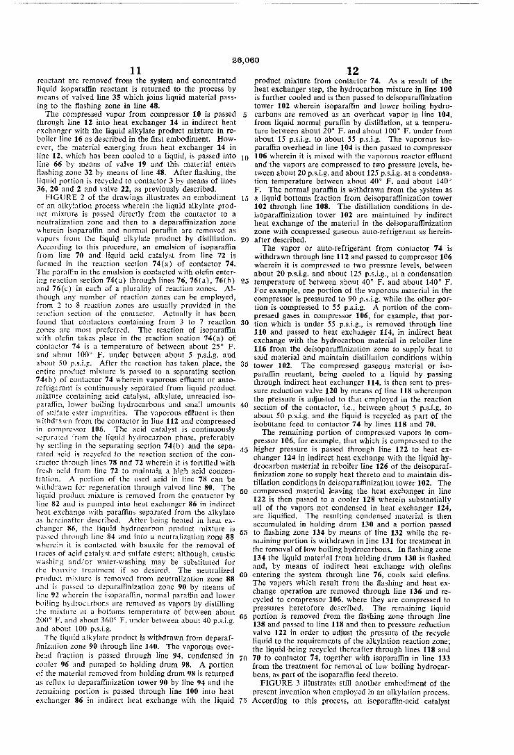
26,060 11
reactant are removed from the system and concentrated liquid isopara?in reactant is returned to the process by means of valved line 35 which joins liquid material pass ing to the ?ashing zone in line 48. The compressed vapor from compressor 10 is passed
through line 12 into heat exchanger 14 in indirect heat exchanger with the liquid alkylate product mixture in re boiler line 16 as described in the ?rst embodiment. How ever, the material emerging from heat exchanger 14 in line 12. which has been cooled to a liquid, is passed into line 66 by means of valve 19 and this material enters ?ashing zone 32 by means of line 48. After ?ashing, the liquid portion is recycled to contactor 3 by means of lines 36, 20 and 2 and valve 22, as previously described. FIGURE 2 of the drawings illustrates an embodiment
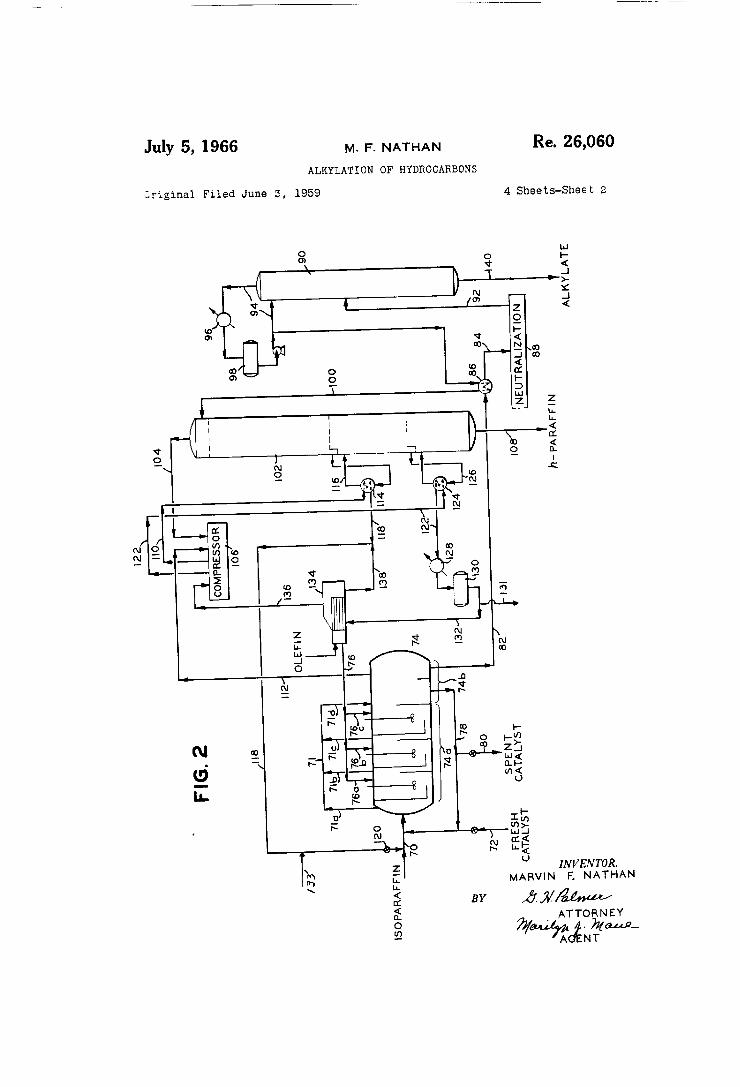
of an alkylation process wherein the liquid alkylate prod uct mixture is passed directly from the contactor to a neutralization zone and then to a depara?inization zone wherein isoparatiin and normal paraf?n are removed as vapors from the liquid alkylate product by distillation. According to this procedure, an emulsion of isoparat?n from line 70 and liquid acid catalyst from line 72 is formed in the reaction section 74(a) of contactor 74. The paraffin in the emulsion is contacted with ole?n enter ing reaction section 74(a) through lines 76, 76(3), 76(b) and 76(c) in each of a plurality of reaction zones. Al though any number of reaction zones can be employed, from 2 to 8 reaction zones are usually provided in the reaction section of the contactor. Actually it has been found that contactors containing from 3 to 7 reaction zones are most preferred. The reaction of isopara?‘in with ole?n takes place in the reaction section 74(a) of contactor 74 is a temperature of between about 25° F. and about 100° F. under between about 5 p.s.i.g. and about 50 p.s.i.g. After the reaction has taken place, the entire product mixture is passed to a separating section 74th) of contactor 74 wherein vaporous eltluent or auto refrigerant is continuously separated from liquid product mixture containing acid catalyst, alltylate, unreacted iso para?in, lower boiling hydrocarbons and small amounts of sulfate ester impurities. The vaporous e?luent is then withdrawn from the contactor in line 112 and compressed in compressor 106. The acid catalyst is continuously separated from the liquid hydrocarbon phase, preferably by settling in the separating section 74(b) and the sepa rated acid is recycled to the reaction section of the con tractor through lines 78 and 72 wherein it is forti?ed with fresh acid from line 72 to maintain a high acid concen tration. A portion of the used acid in line 78 can be withdrawn for regeneration through valved line 80. The liquid product mixture is removed from the contactor by line 82 and is pumped into heat exchanger 86 in indirect heat exchange with para?ins separated from the alkylate as hereinafter described. After being heated in heat ex changer 86, the liquid hydrocarbon product mixture is passed through line 34 and into a neutralization Zone 88 wherein it is contacted with bauxite for the removal of traces of acid catalyst and sulfate esters; although, caustic washing and/or water-washing may be substituted for the bauxite treatment if so desired. The neutralized product mixture is removed from neutralization zone 88 and is passed to deparatlinization zone 90 by means of line 92 wherein the isoparaf?n, normal paraflin and lower boiling hydrocarbons are removed as vapors by distilling the mixture at a bottoms temperature of between about 200° F. and about 360° F. under between about 40 p.s.i.g. and about 100 p.s.i.g. The liquid alkylate product is withdrawn from deparaf
?nization zone 90 through line 140. The vaporous over head fraction is passed through line 94, condensed in cooler 96 and pumped to holding drum 98. A portion of the material removed from holding drum 98 is returned as re?ux to depara?inization tower 90 by line 94 and the remaining portion is passed through line 100 into heat exchanger 86 in indirect heat exchange with the liquid
10
15
20
25
30
40
50
55
60
05
70
.12 product mixture from contactor 74. As a result of the heat exchanger step, the hydrocarbon mixture in line 100 is further cooled and is then passed to deisopara?‘inization tower 102 wherein isoparaf?n and lower boiling hydro carbons are removed as an overhead vapor in line 104, from liquid normal paraffin by distillation, at a tempera ture between about 20° F. and about 100° F. under from about 15 p.s.i.g. to about 55 p.s.i.g. The vaporous iso parat?n overhead in line 104 is then passed to compressor 106 wherein it is mixed with the vaporous reactor effluent and the vapors are compressed to two pressure levels, be tween about 20 p.s.i.g. and about 125 p.s.i.g. at a condensa tion temperature between about 40° F. and about 140° F. The normal para?in is withdrawn from the system as a liquid bottoms fraction from deisopara?inization tower 102 through line 108. The distillation conditions in de isoparat?nization tower 102 are maintained by indirect heat exchange of the material in the deisoparaf?nization zone with compressed gaseous auto-refrigerant as herein after described. The vapor or auto-refrigerant from contactor 74 is
withdrawn through line 112 and passed to compressor 106 wherein it is compressed to two pressure levels, between about 20 p.s.i.g. and about 125 p.s.i.g., at a condensation temperature of between about 40° F. and about 140° F. For example, one portion of the vaporous material in the compressor is pressured to 90 p.s.i.g. while the other por tion is compressed to 55 p.s.i.g. A portion of the com pressed gases in compressor 106, for example, that por tion which is under 55 p.s.i.g., is removed through line 110 and passed to heat exchanger 114, in indirect heat exchange with the hydrocarbon material in reboiler line 116 from the deisopara?inization zone to supply heat to said material and maintain distillation conditions within tower 102. The compressed gaseous material or iso paraf?n reactant, being cooled to a liquid by passing through indirect heat exchanger 114, is then sent to pres sure reduction valve 120 by means of line 118 whereupon the pressure is adjusted to that employed in the reaction section of the contactor, i.e., between about 5 p.s.i.g. to about 50 p.s.i.g. and the liquid is recycled as part of the isobutane feed to contactor 74 by lines 118 and 70. The remaining portion of compressed vapors in com
pressor 106, for example, that which is compressed to the higher pressure is passed through line 122 to heat ex changer 124 in indirect heat exchange with the liquid hy drocarbon material in reboiler line 126 of the deisoparaf ?nization zone to supply heat thereto and to maintain dis tillation conditions in deisoparaf?nization tower 102. The compressed material leaving the heat exchanger in line 122 is then passed to a cooler 128 wherein substantially all of the vapors not condensed in heat exchanger 124, are liqui?ed. The resulting condensed material is then accumulated in holding drum 130 and a portion passed to ?ashing zone 134 by means of line 132 while the re maining portion is withdrawn in line 131 for treatment in the removal of low boiling hydrocarbons. In ?ashing zone 134 the liquid material from holding drum 130 is ?ashed and, by means of indirect heat exchange with ole?ns entering the system through line 76, cools said ole?ns. The vapors which result from the ?ashing and heat ex change operation are removed through line 136 and re cycled to compressor 106, where they are compressed to pressures heretofore described. The remaining liquid portion is removed from the ?ashing zone through line 138 and passed to line 118 and then to pressure reduction valve 122 in order to adjust the pressure of the recycle liquid to the requirements of the alkylation reaction zone; the liquid ‘being recycled thereafter through lines 118 and 70 to contactor 74, together with isopara?in in line 133 from the treatment for removal of low boiling hydrocar bons, as part of the isopara?in feed thereto. FIGURE 3 illustrates still another embodiment of the
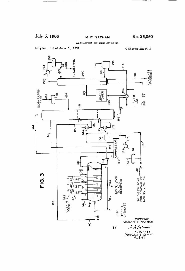
present invention when employed in an alkylation process. According to this process, an isopara?in-acid catalyst

26,060 13
emulsion is reacted with ole?n from lines 142-142(d) in reaction section 144(a) of a cascade alkylation reactor 144. The isoparaf?n enters the reaction section from line 146 from a source hereinafter described, while acid is introduced through line 148 and emulsi?ed with isoparaf ?n prior to contact with ole?n. The reaction takes place upon contact of ole?n with the emulsion at a temperature of between about 25° F. and about 100° F. under from about 5 p.s.i.g. to about 50 p.s.i.g. After the reaction is completed, the product mixture is transferred to a separat ing section 144(1)) within reactor 144 wherein a vaporous effluent or auto-refrigerant containing isoparaf?n and lower boiling hydrocarbons, is separated from a liquid phase containing alkylate, acid catalyst, isopara?in, normal para?‘in and contaminants. vaporization of the lower boiling components in each reaction zone during the alkylation reaction is ettected as a temperature control and the total of these vaporized components comprise the auto-refrigerant removed from the liquid product mix ture and thence from the reactor in line 166. The liquid phase is separated, preferably by settling,
into in acid catalyst phase and a liquid product mixture or hydrocarbon phase containing in addition to hydro carbons, contaminants, such as, for example, sulfate ester by-products of the reaction and traces of acid catalyst. The acid phase is withdrawn from the reactor by line 150 and a portion recycled through line 148 wherein it is forti ?ed with fresh acid to maintain a high acid concentra tion, preferably between about 85 percent to about 99 percent acid. A portion of the used acid is withdrawn from the system through valved line 152 and may be re generated if desired. The liquid product mixture is withdrawn from reactor
144 and transferred to deisopara?inization tower 156 by means of line 154. Fresh isopara?in required for the alkylation reaction to provide a mol ratio of between about 2:1 and about 150:1 isoparaf?mole?n in the re action zones is introduced into deisopara?‘inization tower 156 by line 158 from holding drum 160. The liquid prod uct mixture is stripped of isoparat?n reactant and lower boiling hydrocarbons in tower 156 at a bottom tempera ture of between about 50° F. and about 200° F. under tower top pressure from about 0 p.s.i.g. to about 60 p.s.i.g. The isopara?in and lower boiling hydrocarbons are re
moved from tower 156 as a vaporous overhead fraction and are passed by line 164 to compressor 162 wherein they are compressed to two pressure levels ranging from pres sures between about 20 p.s.i.g. and about 125 p.s.i.g. at condensation temperatures between about 40° F. and about 140° F. The vaporous auto-refrigerant is transferred by line
166 from reactor 144 to compressor 162 wherein the auto refrigerant is compressed to two pressure levels ranging from pressures between about 20 p.s.i.g. and about 125 p.s.i.g. at condensation temperatures from about 40° F. to about 140° F. When the vapors passed to compressor 162 are com—
pressed to different pressures and in accordance with the teaching of the invention the most highly compressed vapor is used to supply heat to a lower portion of the de isopara?'inization tower than the vapor compressed to a lower pressure. Therefore, vapors compressed to be— tween about 20 p.s.i.g. and about 50 p.s.i.g. are removed from the compressor by line 186 and passed to heat cx changer 184 while the vapors compressed to between about 40 p.s.i.g. and about 125 p.s.i.g. are removed from the compressor by line 168 and used in heat exchanger 170. A portion of the vapors in line 168 is passed to heat exchanger 170 in indirect heat exchange with the liquid product mixture in rcboiler line 172 of tower 156. The remaining portion of compressed vapors is passed to by-pass line 174 into cooler 176, wherein substantially all of the vapor is condensed, and then into holding drum 178 from whence a portion of the liquid material is removed from the system through line 180 for further
10
El
L10
60
14 treatment in the removal of parai?ns boiling below the isoparaf?n reactant (not shown). The remaining por tion of liquid from holding drum 178 is passed to line 182 and joins condensed heat exchange medium leaving heat exchanger 170 in line 168. The condensed liquid, predominately isopara?in reactant, is passed upwardly through line 182 to the compressed, vaporous heat ex change medium entering a more elevated heat exchanger 184 from line 186 into indirect heat exchange with the liquid product mixture in rcboiler line 188 of the deiso parai?nization zone. This gaseous-liquid mixture sup— plies heat to the liquid product mixture and maintains distillation temperature in the deisoparat?nization tower. The gas of the heat exchanger medium is condensed by the heat exchange operation and resulting liquid is trans ferred to a pressure reduction valve 190 by line 192 prior to entry into isoparatlin recycle line 146. By means of valve 190 the pressure of the liquid isopara?in is ad~ justed to a pressure suitable for alkylation. The deisoparatlinized product mixture in tower 156 is
removed as a liquid by line 196 and is pumped to heat exchanger 194 in indirect heat exchange with a rcboiler line hereinafter described. The product mixture which is heated in heat exchanger 194 is then passed to a neu tralization zone 198 wherein it is washed with water at an elevated temperature between about 100° F. and about 150° F., and is then passed through a coalescer (not shown) to separate and remove the water before the prod uet mixture is passed through line 196 into depara?iniza tion tower 200. Normal para?in is separated from the alkylate product by distillation at a temperature between about 200° F. and about 360° F. under between about 40 p.s.i.g. and about 100 p.s.i.g. in tower 200. The nor mal paraf?n which is removed as an overhead vapor in line 202 is cooled to a liquid in condenser 204, passed to accumulator 206 and a portion returned to the top of tower 200 by line 202. The remaining portion of nor mal paraffin leaving accumulator 206 is pumped out of the system in line 208.
Rcboiler liquid is withdrawn from the bottom of tower 200 by line 210, pumped to heat exchanger 194 to supply heat to the product mixture entering the water wash 198 or pumped to valved heater by-pass line 212 which is provided for temperature control. The rcboiler liquid from line 212 is combined with reboiler liquid from heater 194 in line 214 and the combined liquid is then passed from line 214 into heater 215 wherein the reboiler liquid is heated and partially vaporized at a temperature necessary to maintain the distillation temperature in tower 200 and then returned to tower 200 by line 216. The liquid alkylate product in tower 200 is withdrawn
as a product of the process by line 218 or further sepa rated into light and heavy alkylate by passing it from line 218 into an alkylate rerun tower or distillation zone (not shown) wherein light alkylate for example, avia tion gasoline, is withdrawn from the top of the tower and heavy alkylate is withdrawn from the bottom of the rerun tower.
FIGURE 4 illustrates another modi?cation of the pres ent invention wherein the alltylation reaction in con tactor 220 is substantially as described above in any of the preceding ?gures. lsopara?in enters the contactor from line 222 and is emulsi?ed with acid catalyst en~ tering the contactor from line 224. The emulsion is then reacted with ole?n which is separately introduced into each of a plurality of reaction zones through lines 226, 226(a), 226th), 226(c) and 226(d) in the reaction section 220t'a) of contactor 220. After passing the emul sion serially through each of the reaction zones, remov ing the reaction vapors from each zone through lines 228, 228(a), 228(b), 228(c) and 228(d) and returning the vapors to the contactor through line 228(e), the en tire reaction mixture is passed to the separation section 20(b) of contuctor 220 wherein the vapors are passed through coalcscer 230 to separate liquid entrained there

26,060 15
with, the vapors being passed to line 232 while the sepa rated liquid is returned to the liquid phase entering the separation section. The combined liquid is passed through coalescer 234 to break the acid catalyst-liquid hydrocar bon emulsion. The liquid is then allowed to settle and acid catalyst is separated from the liquid hydrocarbon product mixture. Recycle line 236 is provided for re moving the acid catalyst from the separation section, pumping it to line 224 wherein it is mixed with a su?i cient amount of fresh acid to maintain the concentra tion at between about 85 percent and 99 percent H2504. The concentrated acid is then returned to the contactor for emulsi?cation with isoparatiin. A portion of the spent acid is withdrawn from line 236 through valved line 238, passed to an additional settler 240 in order to recover and remove in line 242 any of the liquid product mixture entrained therewith. The spent acid is then sent to an acid recovery system (not shown) for concentration while the separated liquid product mixture in line 242 is passed to deisoparat?nization tower 244. The liquid alkylate product mixture separated in the
contactor is pumped through line 248 into coalescer 246 to further separate acid catalyst. The liquid product mixture is then withdrawn from coalescer 246 and pumped through line 250 into deisopara?inization tower 244. In tower 244, vaporous isopara?in and lower boil ing hydrocarbons are stripped from the liquid product mixture at a tower top temperature of between about 20° F. and about 100° F., under from about 0 p.s.i.g. to about 60 p.s.i.g. The vapors are removed overhead in line 254 and passed to a compressor 252 wherein they are compressed to a pressure of between about 25 p.s.i.g. and about 125 p.s.i.g. at a condensation temperature from about 50° F. to about 140° F. The vaporous e?luent or auto-refrigerant removed from
the contactor in line 232 is passed to compressor 252 wherein they are compressed to a pressure and tempera ture within the above-mentioned range. Herein the process departs from the previously de
scribed embodiments. Valves 254 through 257 and 281 are opened and valves 258 through 261 are closed. A stream of compressed gas is withdrawn from compressor 252 in line 262 and a portion, necessary to maintain the temperature of distillation in tower 244, is passed to heat exchanger 264 in indirect heat exchange with the trap-out liquid in reboiler line 266 to supply the neces sary heat thereto. In the heat exchange operation, the compressed gas is partially condensed and the partially condensed material is passed through line 268 wherein it is joined by the remaining portion of compressed gas which by-passes the heat exchanger in valved line 270. The entire compressed gaseous-liquid heat exchange media is then passed to condenser 272 wherein the entire mixture is cooled to a liquid. The resulting liquid is transferred to a ?rst ?ashing zone 274 from which a liquid portion is removed through line 276 and passed to heat exchanger 278 through valved line 279. A portion of the gas is removed from the ?rst ?ashing zone 274 and passed to heat exchanger 278 through valved lines 280 and 315 for indirect heat exchange with the liquid portion previously mentioned from zone 274 and the re maining portion of gas in line 280, controlled by valve 281, is passed on through line 280 for return to compres sor 252, wherein it is pressured to between about 20 p.s.i.g. and about 125 p.s.i.g. The gas entering heat exchanger 278 is condensed and
transferred to holding drum 284 by line 282 while the liquid entering heat exchanger 278 from line 279 is ?ashed and partially vaporized; the vaporized portion being passed through valved line 286 which joins line 280 for recycle to the compressor ‘by way of line 280. The remaining liquid portion in heat exchanger 278 is with drawn by line 288 and split into two portions, one of which is passed to pressure reduction valve 290 and re cycled to the reaction section of contactor 220 as part of
10
20
30
40
45
60
70
75
16 the isopara?in feed thereto through line 222 and the sec ond of which is withdrawn from line 288 by valved line 289 and passed to holding drum 284. The combined liquid in holding drum 284 has a
higher concentration of low boiling materials than either the auto-refrigerant stream or the deisopara?‘inization tower overhead by reason of the ?ashing and separating operation in zone 274. The materials boiling below the isopara?in reactant are removed from the system by pass ing the combined liquid from holding drum 284 to a dis tillation zone (not shown) by means of line 292. In this distillation zone, the lower boiling materials are re moved from the system as a vaporous overhead fraction while the isoparatlin reactant, which is removed as a liquid bottoms fraction is returned to the reactor by line 294. The advantage attained by this arrangement is that smaller volumes of liquid are distilled for a given volume of lower boiling materials removed from the system. Therefore, a smaller more e?icient distillation zone can be employed in this embodiment of the present process. The total portion of liquid in drum 284 is withdrawn
by line 292 and is pumped to a distillation zone (not shown) for removal of hydrocarbons boiling below the isoparafhn reactant, after which, the concentrated iso paral’?n reactant is returned to the recycle stream by means of line 294. The liquid alkylate product mixture is withdrawn from
the deisopara?inization tower 244 ‘by line 296, passed to a neutralization zone 298 wherein sulfate esters and other impurities are removed in accordance with teachings de scribed above. The product mixture is thcn passed to deparaf?nization zone 300 from line 302 wherein the ulkylate is separated from normal paraffin at a tempera ture of between about 200° F. and about 360° F. under from about 40 p.s.i.g. to about 100 p.s.i.g. The normal paral?n is removed from zone 300 as an overhead vapor stream, a portion of which serves as re?ux to the tower, and the liquid alkylate product is withdrawn therefrom by line 304 and passed to rerun tower 306 operating at a bottoms temperature of between about 250° F. and about 450° F. under tower top pressure from 0 p.s.i.g. to 20 p.s.i.g. A light alkylate fraction is removed from tower 306 as an overhead vapor, condensed in re?ux line 308 by means of condenser 310 and a portion of the resulting liquid removed as a product of the process‘, ‘the remain ing portion serving as re?ux to the tower. A heavy liquid alkylate fraction is removed from the bottom of tower 306 in line 312 as the heavy alkylate product of this process.
In a second modi?cation of the process of this inven tion the process steps, including the alkylation reaction, deisopara?inization, compression and indirect heat ex change in heat exchanger 264 are exactly the same as those previously described in FIGURE 4. This process departs from the previous process in that valves 256, 257 and 255 are closed while valves 258, 259, 260 and 261 are opened and the vapor from ?ashing zone 274 in place of being passed in indirect heat exchange with the liquid portion from 274, is passed in indirect heat exchange in ?ashing zone 278 with trap-out liquid in lines 314 and 315 from tower 244 to supply heat thereto and to main tain the distillation temperature in tower 244. The vapor from ?ashing zone 274 is passed through valved line 316 into heat exchanger 278 where part or all of it condenses. The vapor portion ?ows through lines 286 and 280 for compression in compressor 252, while a portion of the liquid is recycled to contactor 220 through line 288 and the remaining portion is passed to holding drum 284 by means of valved line 289. The liquid portion from the First ?ashing zone 274 passes through valved lines 276 and 318 and into line 288 for recycle to the reaction sec tion of contactor 220. The remaining steps of the proc ess, namely the treatment of the deisopara?inized alkylate, including neutralization, deparat?nization, and distilla tion to separate light and heavy alkylate fractions, are
26,060 17
substantially the same as those described above for FIG URE 4. The following examples are offered as a better under
standing of the present invention and are not to ‘be con— strued as unnecessarily limiting to the scope thereof. The examples are carried out according to the teachings of the speci?cation and the drawings described above.
EXAMPLE I
Into a cascade alkylation reactor is ‘fed a continuous stream of isobutane containing about 15 percent normal butane and sulfuric acid of about 98 percent concentra tion in a mo] ratio of about 7: 1. The isobutane and sul furic acid catalyst are emulsi?ed and passed to a con?ned reaction zone wherein the emulsion is contacted with butylene in a mole ratio of about 20:1 isobutanezbutyl one. The reaction between the isobutane and butylene to form octanes takes place at 40° F. under about 11 p.s.i.g. in a plurality of con?ned reaction zones through which the emulsion is passed serially while contacting butylene introduced separately into each zone. The re sulting reaction product mixture is then passed to a separating zone wherein vapors formed during the reac tion, comprising isobutane, and lower boiling hydrocar bons such as propane are separated from a liquid phase containing isobutane, n-butane, alkylate product, sulfuric acid and small amounts of ibutyl sulfates. The liquid phase passed through a wire mesh screen and is ‘allowed to settle for about 10 minutes after which the acid which ‘separates from the hydrocarbon liquids is withdrawn and recycled to the reaction zone. The hydrocarbon liquids or alkylate product mixture
is withdrawn from the reactor at a temperature of about 45° F. under about 8 p.s.i.g. and is passed through a coalescer to further separate entrained acid and sulfur bearing impurities therefrom. The liquid product mix ture is then transferred to a deisobutanization tower wherein the liquid is stripped of isobutane and lower boiling hydrocarbons such as propane. The vaporous material is withdrawn from the reactor at a temperature of about 45° F. under about 8 p.s.i.g. and passed to a coalescer wherein entrained liquid is separated there from. The vapors are then transferred to a compressor from which two compressed vaporous streams are with drawn; one at 47 p.s.i.g. and the other at 80 p.s.i.g. The compressed vaporous stream under 47 p.s.i.g. is passed in indirect heat exchange with the liquid material in the deisobutanization tower to supply heat thereto and to maintain the distillation temperature within the stripping tower. For example, the compressed gas at a condensation temperature of 65° F. is passed in in direct heat exchange with liquid material leaving the deisobutanization tower in a reboiler line at about 53° F. and returning liquid material to the deisobutaniza tion tower at 58° F. The top of the deisobutanization tower is maintained at a pressure of about 16 p.s.i.g. and about 26° F. while the bottom of the tower is main tained under about 21 p.s.i.g. and about 84° F. Vapor ous isobutane and lower boiling components are re moved from the top of the deisobutanization tower at about 26° F. and passed to the compressor. The heat exchange media which has been condensed by heat ex change with the liquid product mixture in the deisobu tanization zone is then passed to a pressure reduction valve wherein the pressure is reduced from 47 p.s.i.g. to about 26 p.s.i.g. ‘and the resulting liquid is then re cycled to the alkylation reaction zone for further con— tact with butylene. Part of the vaporous stream which has been compressed to 80 p.s.i.g. at a temperature of 120° F. is passed to a condenser wherein the tempera ture is lowered to 100° F. for the total liqui?oation of the vapors while another portion is passed in indirect heat exchange with a trap-out liquid entering bottom reboiler at 65° F. and returning to the tower as a liquid vapor mixture at 89° F. The resulting liquid streams
10
30
40
60
70
75
18 from the bottom reboiler and condenser are then mixed with the heat exchange media prior to heat exchange in the upper reboiler. The deisoparaftinized liquid product mixture is re—
moved from the bottom of the deisobutanization tower at a temperature of about 84° F. and is washed with water at a temperature of about 140° F. for removal of traces of sulfur-bearing contaminants. The wash water is discarded as the liquid product mixture passes through a coalescer and the hydrocarbon is then trans ferred to a debutanization zone wherein, at a bottom temperature of about 330° F., under 80 p.s.i.g., normal butane is separated ‘from the alkylate product. This alkylate product is then further fractionated in a rerun tower to obtain a fraction of aviation gasoline and a higher boiling fraction comprising heavy alkylate. The invention as described herein relates to an im
proved method for reboiling a distillation tower. This method comprises reacting hydrocarbons under such con ditions that a vaporous etiluent and a liquid product etlluent are produced, passing the liquid e?luent to a dis tillation zone to remove one of the liquid components boiling below said product, compressing the vaporous etlluent to one or more pressure levels and passing the compressed vapors in indirect heat exchange with said zone, the vapors being compressed to a pressure at which the temperature of the vaporous eliiuent is above the boiling point of the ‘boiling point of the component to be removed, below the boiling point of the reaction product and that at which at least part of the vapors are condensed during the heat exchange operation. When the vaporous et?uent contains a reactant of the
reaction, the reactant is generally recovered, condensed and recycled to the reaction zone. When the lower boil— ing component removed from the distillation zone as a vapor also contains reactant, this vapor can be combined with the vaporous efiluent and the combined vapors com pressed and passed in indirect heat exchange with the distillation tower to reboil said tower. Although the above described improvement relates particularly to al~ kylation reactions, it is to be understood that other types of reactions, wherein a vaporous efiluent is produced and a liquid pro-duct effluent is produced for subsequent dis tillation, are also within the scope of this invention. The method for reboiling the deisopara?‘inization tower
can be any of the procedures herein described, and nu merous modi?cations and alterations of these procedures will become apparent to those skilled in the ‘art without departing from the scope of this invention. Having thus described my invention I claim: 1. In an alkylation process which comprises contact
ing isobutane with an ole?n in the presence of sulfuric acid in an alkylation contractor to produce a vaporous hydrocarbon ellluent containing isobutane ‘and ‘a liquid eflluent containing sulfuric acid, alkylate and unreacted isobutane; separating vaporous ef?uent from the liquid effluent; separately removing sulfuric ‘acid from the liquid effluent; and subjecting the resulting liquid alkylate mix ture to cleisobutanization; the improvement which com prises: passing the liquid alkylate mixture to a deisobu tanization zone; removing isobutane ‘as a vaporous frac tion from said zone; compressing the vaporous fraction and the vaporous e?luent to the pressure levels within the range of between about 20 p.s.i.g. and about 125 p.s.i.g. at a condensation temperature of between about 40° F. and about 140° F.; maintaining as two distinct and separate streams the vapors compressed to different pressure levels ‘supplying heat necessary to effect the ‘aforementioned deisobutanization of said liquid alkylate mixture in said zone by passing the vapor compressed to the lower pressure in indirect heat exchange with the deisobutanization zone in a ?rst heat exchanger to re boil said zone, and passing the vapor compressed to the higher pressure in indirect heat exchange with the deiso butanization zone at a point below said ?rst heat ex

26,060 19
changer to reboil said zone in a second heat exchanger; condensing the low pressure vapor in said ?rst heat ex change operation; recycling the resulting liquid to the alkylation contactor as part of the isobutane feed there to; condensing the higher pressure vapor and ?ashing the resulting condensate in a third heat exchanger to pro duce a vaporous phase and a liquid phase; recycling the vaporous phase to said compression step; recycling the liquid phase to the alkylation contactor as part of the isobutane feed thereto and recovering a deisobutanized ‘alkylate mixture from the deisobutanization zone.
2. The process of claim 1 wherein ole?n is cooled in said third heat exchanger before entering the alkylation contactor.
3. The process of claim 1 wherein the liquid in the de isobutanization zone is further rehoiled by indirect heat exchange of the liquid alkylate mixture with the mate rial in the third heat exchanger.
4. In an alkylation process which comprises contact ing an ole?n with an isopra?in in the presence of sul furic acid as a catalyst in an alkylation contactor to pro duce a vaporous hydrocarbon ef?uent containing un reacted isoparat?n and a liquid ef?uent containing cata lyst, alkylate, normal para?in and unreacted isoparaihn; separating the vaporous e?luent from the liquid e?iuent; separately removing the catalyst from the liquid e?luent; and subjecting the remaining liquid alkylate mixture to deparaf?nization; the improvement which comprises: passing the liquid alkylate mixture to a deparaliinization zone and withdrawing unreacted isopara?in as a vaporous overhead fraction, normal para?in as a vaporous middle fraction and liquid alkylate as a liquid bottom fraction from said depara?‘inization zone; recovering alkylate from the bottom fraction as a product of the process; compressing a mixture of the vaporous overhead fraction and the vaporous e?iuent to a plurality of di?erent pres sure levels; maintaining as distinct and separate streams each of the vapors compressed to a different pressure; re boiling the upper portion of said zone from which the vaporous overhead fraction is removed by passing the vapor compressed to the lowest pressure level in indirect heat exchange with the liquid in said upper portion of said deparaf?nization zone; passing vapor compressed to an intermediate pressure level in indirect heat exchange with the liquid in the middle portion of said zone from which normal para?in is removed to reboil said middle portion of said deparaf?nation zone; passing the vapor compressed to the highest pressure level in indirect heat exchange with the bottom portion of said zone from which liquid alkylate product is removed to supply at least a por tion of the heat necessary to reboil said bottom portion of the deparal?nization zone; and condensing compressed vapors in each of the heat exchange operations.
5. In alkylation process which comprises contacting an ole?n with an isoparaf?n in the presence of sulfuric acid as a catalyst in an alkylation contactor to produce a vaporous hydrocarbon e?luent containing unreacted iso para?in and a liquid e?luent containing catalyst, alkylate, normal para?in and unreacted isopara?in; separating the vaporous e?luent from the liquid e?‘luent; separately re moving the catalyst from the liquid effluent; and sub jecting the remaining liquid alkylate mixture to deiso para?inization; the improvement which comprises: pass ing the liquid alkylate mixture to a depara?inization zone which is operated as a stripper, substantially without re?ux; withdrawing unreacted isopara?‘in as a vaporous overhead fraction from said zone; withdrawing normal paraffin as a vaporous side fraction from said zone; con densing said normal para?in and recovering the conden sate as a product of the process; continuously withdraw ing a liquid alkylate stream from the lower portion of said zone; treating the liquid alkylate stream for the neu tralization and removal of contaminants; continuously recycling the decontaminated liquid alkylate stream to
10
40
60
20 the lower portion of said stripping zone; removing de para?inized liquid alkylate from the bottom of said zone as a product of the process; compressing the vaporous overhead fraction and the vaporous etiluent to a plurality of pressure levels varying between about 20 p.s.i.g. and about 125 p.s.i.g. and passing the gaseous stream of each pressure level as an indirect heat exchange medium to a separate heat exchange with liquid from the deisobuta nization zone to reboil said zone at each site of heat exchange and to condense the compressed vapor in the heat exchange operation; passing the condensed vapor to a ?ashing zone; passing the liquid portion from said ?ash ing zone to a separate heat exchanger; withdrawing and recycling the liquid from said separate heat exchanger to the alkylation contactor as part of the isoparal?n feed thereto; returning the vaporous portion from said sepa rate heat exchanger and a portion of the vapors from said ?ashing zone to said compressor; condensing the remain ing portion of vapors from said ?rst ?ashing zone by in direct heat exchange with the liquid from said ?ashing zone in said separate heat exchanger and passing said condensed vapors to a distillation zone for removal of low boiling materials.
6. In an alkylution process which comprises contacting an isopara?in with an ole?n in the presence of sulfuric acid in an alkylation contactor to produce a vaporous hydrocarbon e?‘luent containing unreacted isopara?in and a liquid e?iucnt containing sulfuric acid, alkylate and unreacted isopara?‘in; scpanrling the vaporous c?‘luent from the liquid effluent, and subjecting at least a portion of the liquid e?‘luenl to dcisopara?inizntion; (he improve ment which comprises: passing at least a portion of the liquid c?luent to a deisoparu/?nization zone; removing isopara?in as a vaporous fraction from said zone and removing a liquid alkylate fraction from said zone; com pressing rhe vaporous fraction and the vaporous c?’lucnt to at least two pressure levels within the range of between about 20 p.s.i.g. and about 125 p.s.i.g. at a temperature between about 40° F. and about 140° F.; maintaining as at least two distinct and separate streams the vapors compressed to di?crcnt pressure levels; supplying the heat necessary to e?ect the aforementioned deisopara?ini zation of said liquid c?iuent in said zone by passing at least a portion of the vapor compressed to the lowest pressure in indirect heat exchange with the uppermost portion of the deisoparo?‘inization zone in a ?rst heat ex changer to reboil said zone and passing or least a portion of the vapor compressed to the highest pressure in indi rcct heat exchange with the lowermost portion of the de isoparaf?nization zone to reboil said zone in said second heat exchanger; and condensing compressed vapors dur ing the heat exchange operation.
7. In an alkylation process which comprises contacting isobutane with an ole?n in the presence of sulfuric acid in an alkylan'on contactor to produce a vaporous hydro carbon e?luent containing isobulane and a liquid c?v‘luent containing sulfuric acid, alkylate and unreacted isobumnc; separating the vaporous effluent form the liquid effluent and subjecting the resulting liquid alkylate mixture to de isobutanization; the improvement which comprises: pass ing the liquid alkylate mixture to a dcisobutanizarion zone; removing isobulane as a vaporous fraction from said zone and removing a liquid alkylate fraction from said zone; compressing the vaporous fraction and the vaporous effluent to two pressure levels within the range of between about 20 p.s.i.g. and about 125 p.s.i.g. at a condensation temperature of between about 40° F. and about 140° F.; maintaining as two distinct and separate streams the vapors compressed to di?ercnt pressure levels; supplying heat necessary to c?ccl the aforementioned dc isobutanization of said liquid alkylate mixture in said zone by passing at least a portion of the vapor com‘ pressed to the lower pressure in indirect heat exchange with the dcisobulanizolion zone in a first heat exchanger to reboil said zone, and passing at least a portion of the
26,060 21
vapor compressed to the higher pressure in indirect heat exchange with the deisobutanization zone at a point be low said ?rst heat exchanger to reboil said zone in a second heat exchanger; condensing low pressure vapor in said ?rst heat exchanger operation; condensing higher pressure vapor in said second heat exchanger.
8. The process of claim 7 wherein the liquid effluent contains sulfur-bearing contaminants and the liquid alkylate fraction is subjected to treatment for the removal of sulfur-bearing contaminants.
9. The process of claim 7 wherein a portion of the vapor compressed to the higher pressure is passed in indirect heat exchange with the deisobutanization zone, in a second heat exchanger, to reboil said zone and the remaining portion is passed to said ?rst heat exchanger with the vapor compressed to the lower pressure to reboil said deisobutanization zone.
10. The process of claim 7 wherein a portion of the vapor compressed to the higher pressure is passed in indirect heat exchange with the deisobut-anization zone in said second heat exchanger to reboil said zone and the remaining portion is cooled and separated into a vapor portion and a liquid portion, the liquid portion is recycled to the alkylation contactor as part of the feed thereto and the vapor portion is passed in indirect heat exchange with distilland in an upper portion of the deisobutaniza tion zone to rebotl said zone.
1] . In an alkylation process which comprises contacting isopara?in with an ole?n in the presence of sulfuric acid in an alkylation contactor to produce a vaporous hydro carbon e?‘luertt containing unreacted isoparaf?n and a liquid e?‘luent containing sulfuric acid, alkylate and un reacted isoparaf?n; separating the vaporous e?luent from the liquid effluent; and subjecting the liquid effluent to deisopara?inization; the improvement which comprises: passing at least a portion of the liquid effluent to a deiso para?nization zone; removing unreacted isopara?in as a vaporous fraction from said zone and removing a liquid alkylate mixture from said zone,’ compressing the vapor ous fraction; supplying heat necessary to effect the afore mentioned deisoparafhnization by passing, as a heat ex change medium, in indirect heat exchange with said deisopara?inization zone in a ?rst heat exchanger, at least a portion of the vapors which have been compressed to a pressure at which the temperature is above the boiling point of the isopara?qn reactant, below the boiling point of the higher boiling components of the alkylate mixture and at least at which the vapor is at least partially cott densed during the heat exchange operation; separating the heat exchange medium into vaporous and liquid portions; passing at least a portion of the liquid portion to the alkylation contactor as part of the feed thereto, passing the vaporous portion to a second heat exchanger above said ?rst heat exchanger in indirect heat exchange with said deisoparaf?nization zone, condensing a portion of the vapors during said second heat exchange operation, passing the remaining vaporous portion to said compres sion zone and compressing the vapors therein as part of the heat exchange medium.
12. In an alkylation process which comprises contact ing isopara?‘in with art ole?n in the presence of a catalyst in an alkylation contactor to produce a vaporous hydro carbon e?luent containing unreacted isopara?’in and a liquid e?‘luent containing catalyst, alkylate and unre acted isopara?in; separating the vaporous e?‘luent front the liquid effluent; and subjecting the liquid effluent to deisopara?inization; the improvement which comprises: passing at least a portion of the liquid effluent to a deiso para?inization zone; removing unreacted isopara?‘in as a vaporous fraction from said zone and removing a liquid alkylate fraction from said zone; compressing the vapor ous effluent; supplying heat necessary to e?ect the afore mentioned deisopara?inization by passing, as a ?rst heat exchange medium, in indirect heat exchange with said deisopara?inization zone in Ill ?rst heat exchanger, at
10
4-0
(50
22 least a portion of the vapors which have been compressed to a pressure of between about 20 and about 125 p.s.i.g., and at which the temperature falls within the range of between about 40 and about 140° F., and at which the vapor is at least partially condensed during the heat ex change operation; passing as a second heat exchange medium, at least a portion of the heat exchange medium resulting from the ?rst lteat exchange operation at a di?erent temperature as compared with said ?rst heat exchange medium, in indirect heat exchange with a sec ond portion of the (lClSOPLlI‘CIfj'lIllZtlliOll zone to reboil said zone.
13. The process of claim 12 wherein in at least one heat exchange operation, only a portion of the com pressed vapors as a heat exchange medium is passed to the heat exchange operation and the remaining portion of the heat exchange medium is mixed with the vapors containing condensate withdrawn from the heat exchange operation to regulate the temperature of said compressed vapors containing condensate.
14. The process of claim 13 wherein the compressed vapors containing condensate withdrawn front the heat exchange operation and the compressed vapors which bypass the heat exchange and which have not been cooled by the heat exchange, form a mixture which supplies heat to another portion of the deisoparatfi‘inization zone in a separate heat exchanger by indirect heat exchange with the distiiland in the deisoptara?inization zone.
I5. The process of claim 12 wherein a portion of the condensate formed in at least one heat exchange opera tion is passed to said alkylation contactor as part of the feed thereto.
16. The process of claim 12 wherein at least a portion of the condensate formed in at least one heat exchange operation is employed to cool process feed streams to the alkylation reaction.
17. The process of claim 12 wherein at least a portion of the condensate formed irt at least one heat exchange operation is subjected to distillation to remove materials boiling below said isopana?in reactant from the process.
18. The process of claim II wherein the condensate formed in said ?rst heat exchange operation is returned with condensate formed in said second heat exchange operation to the alkylation contactor, under conditions employed therein, as part of the feed thereto.
19. In an alkylation process which comprises contact ing an ole?n with an isopara?‘in in the presence of sul furic acid as a catalyst in an alkylation contactor to pro duce a vaporous hydrocarbon effluent containing isopar a?in and a liquid e?luent containing catalyst, alkylate, nor mal para?‘in and unreacted isoparaf?n; separating the vaporous e?’luent from the liquid effluent; separately re moving the catalyst from the liquid e?‘luent; and subjecting the remaining liquid alkylate mixture to deisopara?iniza tion, the improvement which comprises: passing the liquid alkylate mixture to a deisoparal?nization zone, withdraw ing unreacted isopara?in as a vaporous fraction front said zone, mixing the vaporous fraction with the vaporous effluent and compressing the vaporous mixture, supplying heat necessary to e?ect the aforementioned deisopara?ini zation by passing, as a heat exchange medium, in indirect heat exchange with said deisopara?‘inization zone, at least a portion of the vapors which ltave been compressed to a pressure at which the temperature is above the boiling point of the isopara?‘in reactant, below the boiling point of the allcylate and normal paraj‘?n components and at least at which the vapor is at least partially condensed during the heat exchange operation, recycling at least a portion of the resulting condensate to the alkylation zone as part of the feed thereto at substantially the same pressure as that employed in the allcylation contactor, removing as bottoms from said deisopara?iniaztion zone a deisopara?inized liquid allcylate mixture containing sulfur-bearing contami nants, subjecting said contaminated alkylate mixture to treatment for the removal of of sulfur-bearing materials,