Frequency Hopping
22
Copyright © 1999 by Ericsson Radio Systems AB 2882-EN/LZT 123 4038 Rev C Frequency Hopping
-
Upload
bouziane-beldjilali -
Category
Documents
-
view
8 -
download
1
Transcript of Frequency Hopping
Copyright © 1999 by Ericsson Radio Systems AB2882-EN/LZT 123 4038 Rev C
Frequency Hopping
Copyright © 1999 by Ericsson Radio Systems AB2882-EN/LZT 123 4038 Rev C
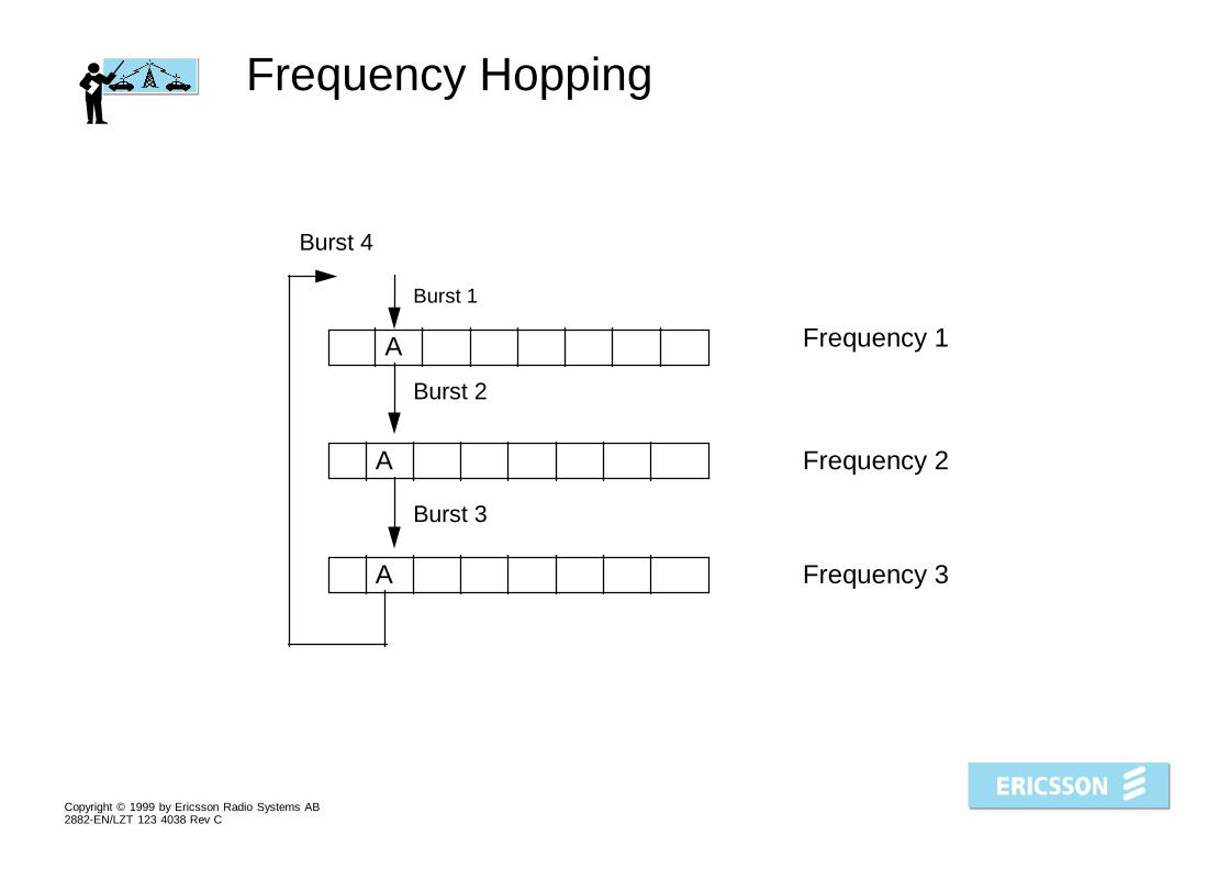
Frequency Hopping
A
A
A
Burst 1
Burst 2
Burst 3
Frequency 1
Frequency 2
Frequency 3
Burst 4

Copyright © 1999 by Ericsson Radio Systems AB2882-EN/LZT 123 4038 Rev C
Frequency Hopping

Copyright © 1999 by Ericsson Radio Systems AB2882-EN/LZT 123 4038 Rev C
Effect on the Air Interface
• Interference averaging
– Gain depends on transceiver distributionand frequency
• Frequency diversity– Gain depends on number of frequencies
and the bandwidth

Copyright © 1999 by Ericsson Radio Systems AB2882-EN/LZT 123 4038 Rev C
Achievements
• More uniform speech quality• A more dependable and predictable radio environment
• Increased capacity (tighter frequency re-use enabled)

Copyright © 1999 by Ericsson Radio Systems AB2882-EN/LZT 123 4038 Rev C
C/I Distributions
C/I
MS
dis
trib
utio
nFHOP
FHOP+BTSPC
FHOP+BTSPC+DTX
Nothing
Acceptable C/Ino FHOP
Acceptable C/IFHOP
Copyright © 1999 by Ericsson Radio Systems AB2882-EN/LZT 123 4038 Rev C
Performance of Frequency Hopping
• Hopping on many frequencies gives betterfrequency diversity and interference averaging.However the relative benefit by adding yetanother frequency will diminish.
• Hopping over a wide band decreases thecorrelation between the fading dips of differentfrequencies thus improving the frequencydiversity.
• A high traffic load will reduce the gain ofinterference averaging.
• Usage of DTX and dynamic power control willincrease the gain of interference averaging.

Copyright © 1999 by Ericsson Radio Systems AB2882-EN/LZT 123 4038 Rev C
A Higher RxQual Can Be Tolerated
Maximum RxQual providing acceptable speech quality
(approx.)No frequency hoppingNo DTX 4.5
Frequency hoppingNo DTX 5-6

Copyright © 1999 by Ericsson Radio Systems AB2882-EN/LZT 123 4038 Rev C
Hopping Sequences - Cyclic and Random
• Cyclic sequence (HSN = 0)
... , I4, I1, I2, I3, I4, I1, I2, I3, I4, I1, I2, ...
• A cyclic sequence is the best sequence for combatingconsecutive fading dips.

Copyright © 1999 by Ericsson Radio Systems AB2882-EN/LZT 123 4038 Rev C
• Random sequences (HSN = 1 - 63)... , I1, I4, I4, I3, I1, I2, I4, I1, I3, I3, I2, ...
• The period of a (pseudo) random sequence is 6 minutes long.
• Random sequences give better interference averaging (if the network is planned using frequency groups.)
• Different random sequences (different HSNs) should be assigned to nearby cells having the same frequencies.
Copyright © 1999 by Ericsson Radio Systems AB2882-EN/LZT 123 4038 Rev C
MS Problems with Random FrequencyHopping?
• MS problem is of no concern any more!(Some MSs have had problems with random frequencyhopping (Siemens and Motorola, very old MS))

Copyright © 1999 by Ericsson Radio Systems AB2882-EN/LZT 123 4038 Rev C
Orthogonal Sequences
• The transmitters in a channel group never use thesame frequency simultaneously.
... , I1, I4, I4, I3, I1, I2, I4, I1, I3, I3, I2,
...
... , I2, I1, I1, I4, I2, I3, I1, I2, I4, I4, I3,
...
... , I3, I2, I2, I1, I3, I4, I2, I3, I1, I1, I4,
...
... , I4, I3, I3, I2, I4, I1, I3, I4, I2, I2, I1,
...

Copyright © 1999 by Ericsson Radio Systems AB2882-EN/LZT 123 4038 Rev C
Two Hopping Modes
• Baseband hopping (FHOP = BB)
• Synthesizer hopping (FHOP = SY)

Copyright © 1999 by Ericsson Radio Systems AB2882-EN/LZT 123 4038 Rev C
Baseband Hopping
controllerTRX1
controllerTRX2
controllerTRX3
controllerTRX4
combiner
bus for routing of bursts
transmitterI�
transmitterI�
transmitterI�
transmitterI�
filter
• Baseband hopping : Each transmitter transmits on a fixed frequency.The bursts from the transceiver controller are routed to the differenttransmitters by a bus.
+ A narrow-band filter combiner can be used. To this combiner it ispossible to connect up to 16 TRXs without more than 3dB combinerloss.
- It is impossible to hop on more frequencies than there are TXs.

Copyright © 1999 by Ericsson Radio Systems AB2882-EN/LZT 123 4038 Rev C
Synthesizer hopping
TRX1
controllerTRX2
controllerTRX3
controllerTRX4
controller
transmitterI�
IQ...
transmitterI�
IQ...
transmitterI�
IQ...
transmitterI�
IQ...
combinerhybrid
combinerhybrid
combinerhybrid
• Synthesizer hopping: The transmitters change frequency for every burst.
+ It is possible to hop on more frequencies than there are transmitters.
- Hybrid combiners must be used. When connecting many transmitters theloss will be big.

Copyright © 1999 by Ericsson Radio Systems AB2882-EN/LZT 123 4038 Rev C
Co Filling at Baseband Hopping
• 30 TCHs and hopping on the BCCH frequency.
controllerTRX1
controllerTRX2
controllerTRX3
controllerTRX4
combiner
bus for routing of bursts
transmitterI�
transmitterI�
transmitterI�
transmitterI�
filter
76�
76�
76�
76�
76�
76�
76�
76�
BCCHI�
I�
I�
I�
ILOOLQJ
F�
ILOOLQJ
F�
ILOOLQJ
F�
ILOOLQJ
F�
ILOOLQJ
F�
ILOOLQJ
F�
ILOOLQJ
F�
TCHTCH
TCH TCHTCHTCH
TCHTCHTCHTCH
TCHTCHTCHTCH
TCHTCHTCHTCH
TCHTCHTCHTCH
TCHTCHTCHTCH
TCH
TCHTCH
SDCCHTCH

Copyright © 1999 by Ericsson Radio Systems AB2882-EN/LZT 123 4038 Rev C
Co Filling at Synthesizer Hopping Withan Extra Transmitter
TRX1
transmitter
controller
TRX2 controller
TRX3 controller
I�
I�
I�
I�
I�
transmitterI�
IQ...
transmitterI�
IQ...
transmitterI�
IQ...
combinerhybrid
combinerhybrid
combinerhybrid
• 22 TCHs and hopping on BCCH frequency.• One transmitter acting only as Co filler.• All traffic bursts that are to be sent on Co are routed to Co transmitter.
7676�
76�
76�
76�
76�
76�
76� �
TCHTCH
BCCH
TCHTCH
TCHTCHTCH
TCHTCHTCH
TCHTCHTCH
TCHTCHTCH
TCHTCHTCH
TCHTCHTCH
SDCCH
IQ
...
I�
I�
I�
I�
ILOOLQJ
F�
ILOOLQJ
F�
ILOOLQJ
F�
ILOOLQJ
F�
ILOOLQJ
F�
ILOOLQJ
F�
ILOOLQJ
F�

Copyright © 1999 by Ericsson Radio Systems AB2882-EN/LZT 123 4038 Rev C
Co Filling at Synthesizer Hopping With anExtra Transmitter and BCCH Controller
TRX1transmitter
controllerTRX2
controllerTRX3
controllerTRX4
I�
I�
I�
I�
BCCHcontroller I
�
transmitterI�
IQ...
transmitterI�
IQ...
transmitterI�
IQ...
combinerhybrid
combinerhybrid
combinerhybrid
• 23 TCHs and hopping on BCCH frequency• One transmitter acting only as Co filler and one “BCCH controller”
makes it possible to use one more TCH compared to the prior case.
• All traffic bursts that are to be sent on Co are routed to thistransmitter.
7676�
76�
76�
76�
76�
76�
76� �
TCHTCH
TCH
BCCH
TCHTCH
TCHTCHTCH
TCHTCHTCH
TCHTCHTCH
TCHTCHTCH
TCHTCHTCH
TCHTCHTCH
SDCCH
IQ
...
I�
I�
I�
I�
ILOOLQJ
F�
ILOOLQJ
F�
ILOOLQJ
F�
ILOOLQJ
F�
ILOOLQJ
F�
ILOOLQJ
F�
ILOOLQJ
F�

Copyright © 1999 by Ericsson Radio Systems AB2882-EN/LZT 123 4038 Rev C
Co Filling at Synthesizer Hopping WithTwo Channel Groups
• 30 TCHs and a non-hopping BCCH frequency.
• If utilization of hardware is more important than it is to hop on theBCCH frequency.
ILOOLQJ
F�
ILOOLQJ
F�
ILOOLQJ
F�
ILOOLQJ
F�
ILOOLQJ
F�
ILOOLQJ
F�
ILOOLQJ
F�
7676�
76�
76�
76�
76�
76�
76� �
IQ
...
I�
I�
I�
I� TCH
TCH
TCHTCHTCH
TCHTCHTCH
TCHTCHTCH
TCHTCHTCH
TCHTCHTCH
TCHTCHTCH
TCHTCHTCH
SDCCH
BCCH TCH TCH TCH TCHTCH TCH TCH
TRX1
controllerTRX2
controllerTRX3
controllerTRX4
controller
transmitterI�
IQ...
transmitterI�
IQ...
transmitterI�
IQ...
transmitterI�
IQ...
combinerhybrid
combinerhybrid
combinerhybrid
Copyright © 1999 by Ericsson Radio Systems AB2882-EN/LZT 123 4038 Rev C
Parameter Summary
Main controlling parameters• HOP is the switch for turning frequency hopping on or off, defined
per channel group. It acts on all channels within the specifiedchannel group. SDCCHs as well as TCHs can hop. A BCCH willnot hop, even if it belongs to a channel group that is configured ashopping.
• HSN is the hopping sequence number, defined per channel group.This parameter specifies which hopping sequence to be used, andacts on all channels within the specified channel group. Alltimeslots in one channel group obtain the same HSN. HSN=0yields a cyclic sequence. HSN=1 to 63 yields (six minutes long)pseudo-random sequences.
Copyright © 1999 by Ericsson Radio Systems AB2882-EN/LZT 123 4038 Rev C
Parameters
• FHOP selects which hopping method to be used, basebandhopping (FHOP=BB) or synthesizer hopping (FHOP=SY). Itis defined per transceiver group (normally one base stationis one transceiver group and one cell).
• COMB specifies which combiner type that has beenconnected, a wide-band hybrid combiner (COMB=HYB) ora narrow-band filter combiner (COMB=FLT). It is definedper transceiver group. If a filter combiner is connected, onlybaseband hopping can be used as hopping method.

Copyright © 1999 by Ericsson Radio Systems AB2882-EN/LZT 123 4038 Rev C
Value Ranges and Default Values
Parameter name Default value Value range Unit
HOP OFF OFF, TCH, ON
HSN 0 to 63
FHOP BB, SY
COMB HYB, FLT