Frequency Agile Ferroelectric Filters, Power Dividers, … · Frequency Agile Ferroelectric...
37
Frequency Agile Ferroelectric Filters, Power Dividers, and Couplers International Microwave Symposium 2009 R. Weigel and E. Lourandakis Workshop WMA
Transcript of Frequency Agile Ferroelectric Filters, Power Dividers, … · Frequency Agile Ferroelectric...

Frequency Agile Ferroelectric Filters,
Power Dividers, and Couplers
International Microwave Symposium 2009
R. Weigel and E. Lourandakis
Workshop
WMA

Outline
• Motivation
• Tunable Passive Components
– Ferroelectric Varactors
• Frequency Agile Filters
• Frequency Agile Power Dividers & Couplers
• Prototype Implementation & Results
• Reconfigurable Amplifier Concept
• Conclusion & Outlook
2

Motivation
• Increasing number of communication bands
• Additional wireless services, e.g. GPS, WiMAX
• Demand for reconfigurable front-end solutions
Motivation
3

Ferroelectric Materials - BST
• Nonlinear response to E
field variation
• Tunability of 60% at 20V
• Voltage and temperature
dependence
• Piezoelectric behavior4

Ferroelectric Thin-Film Varactors
• Metal-Insulator-Metal (MIM)
• Compact dimensions
• Q around 40 @ 2 GHz
• Acoustic resonance
• ADS model available
zero bias
bias 20V
5

• RF “modulates” capacitance
• RF swing is reduced by
cascaded varactors
• Large capacitances are
needed
• Possible for MIM capacitor
Ccas=n x C
Single C
Cascaded C
Pin=20dBm, Bias=20V
Bias=20V
Ferroelectric Thin-Film Varactors
6

Analytical Filter Design – Lowpass
• Chebyshev lowpass filter
• Analytical formulas for
zero locations
7

Frequency Agile Lowpass
• Assumed tunability of 60% for BST varactors
• Multiband tuning from 1.5 – 2.3 GHz
• Changing C results in shifted zero locations
8

Analytical Filter Design – Notch Filter
zero
pole
• Notch filter
• Analytical formulas for zero
and pole locations
9

Frequency Agile Notch Filter
• Assumed tunability of 60% for BST varactors
• Multiband tuning from 1.7 – 2.7 GHz
• Changing C results in shifted zeros and poles
10

Analytical Filter Design – Combline Filter
• Compact filter dimensions
• Most suitable topology
• Asymmetric pole allocation
Tuning principle
11

Modified Combline Filter
• Second attenuation pole
is shifted from DC to
lower stopband
• Symmetric pass- to
stopband transition
OriginalModified
12

λ/4 Based Microwave Circuits
• Well known 3dB couplers
• Based on λ/4 segments
Δφ=0 deg
Δφ=90 deg
Wilkinson divider
Branch-Line coupler
13

Equivalent λ/4 Segments – Distributed Lowpass
• Scalable equivalent circuit
• Signifficant size reduction
Quarter-wavelength segment
Equivalent lowpass segment
(1)
(2)
Comparing (1) and (2) results in
14
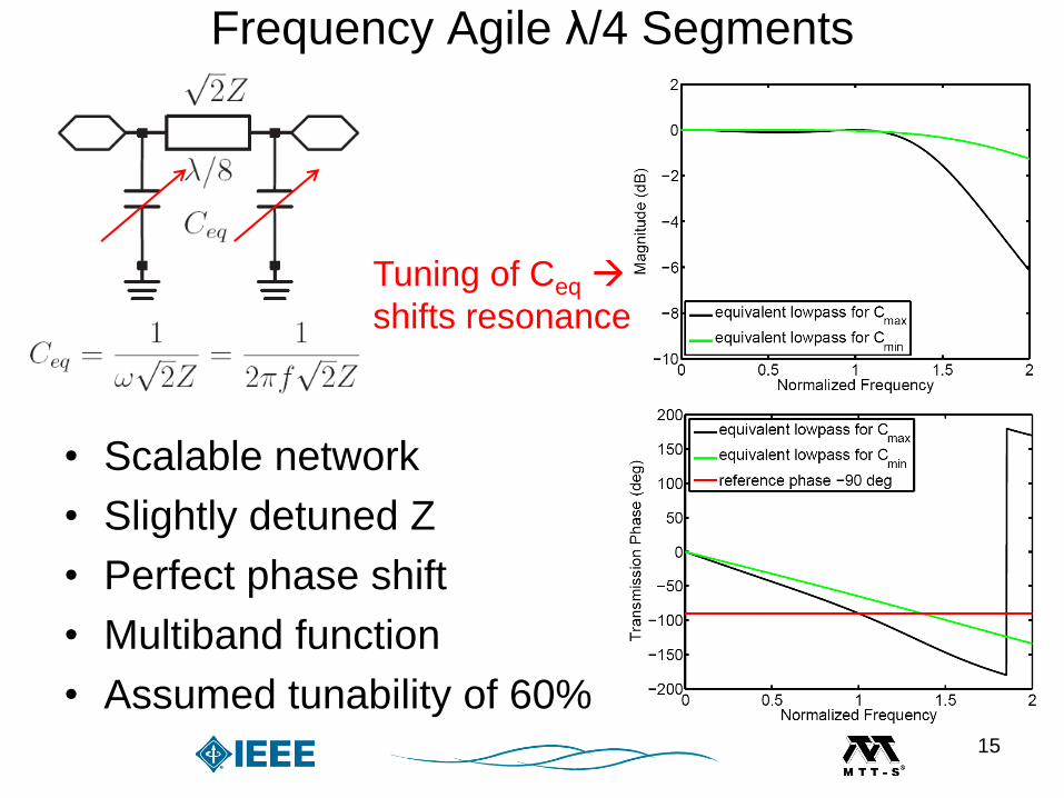
Frequency Agile λ/4 Segments
• Scalable network
• Slightly detuned Z
• Perfect phase shift
• Multiband function
• Assumed tunability of 60%
Tuning of Ceq
shifts resonance
15
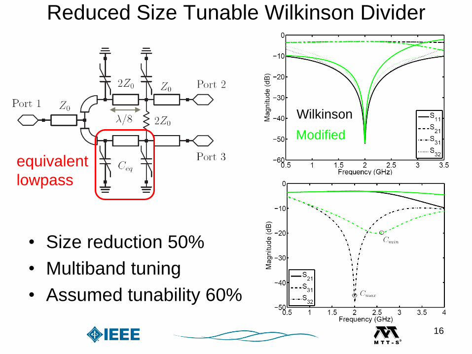
Reduced Size Tunable Wilkinson Divider
• Size reduction 50%
• Multiband tuning
• Assumed tunability 60%
equivalent
lowpass
Wilkinson
Modified
16
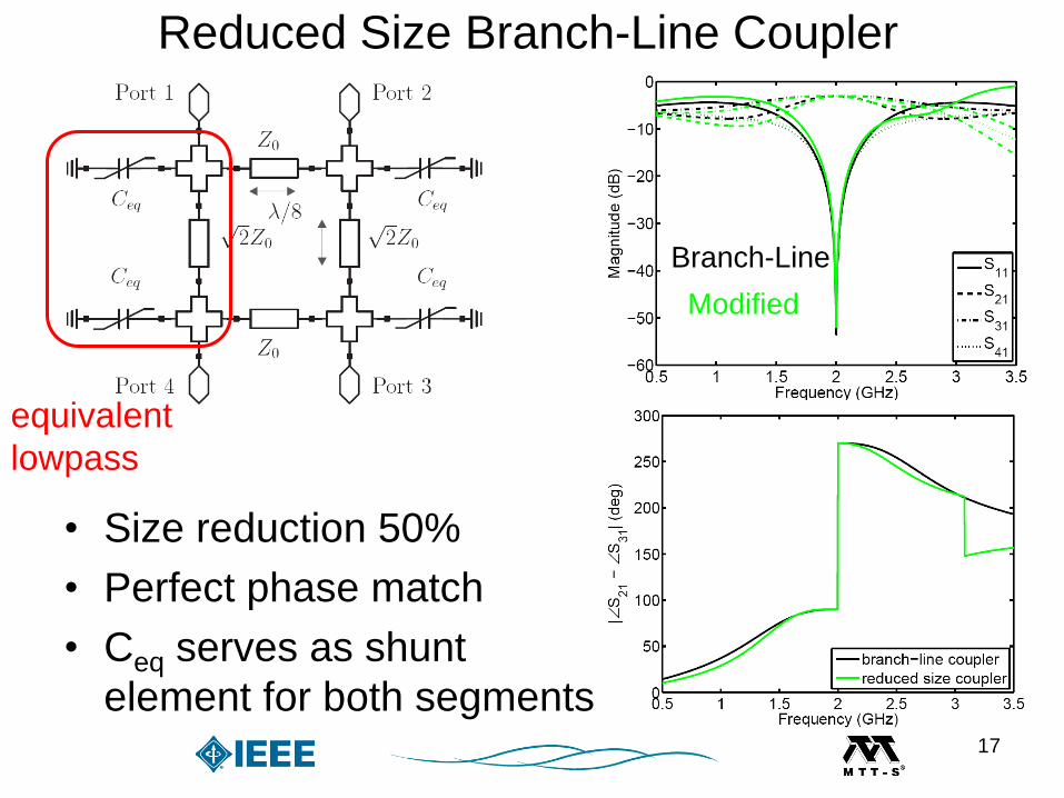
Reduced Size Branch-Line Coupler
• Size reduction 50%
• Perfect phase match
• Ceq serves as shunt
element for both segments
Branch-Line
Modified
equivalent
lowpass
17

Reduced Size Tunable Branch-Line Coupler
• Size reduction 50%
• Perfect phase shift
• Multiband operation with
tunability of 60% for Ceq
equivalent
lowpass
18

Prototype Implementation & Assembly
• Wire assemblies suffer
from parasitics
• Flip-Chip is favorable
• Reduced footprint
Wire inductance
19

Tunable Lowpass (1)
• Biasing components
• Compact dimensions
• Tuning range of 30%
• 1.5-2GHz multiband
• High losses due to
moderate Q and RF
isolation
Biasing elements
20

• Good agreement
• Increased loss due to
varactor imbalances and
prototype assembly
• Two-tone test @
1.95GHz with Δf=5MHz
and Bias=20V
Biasing
Tunable Lowpass (2)
21

Tunable Notch Filter (1)
• Cascaded varactors
simplify biasing
• Compact design
• Tuning 1.5-2.1GHz
• Multiband operation
• Low losses
RF-choke
S21
22

RF-choke
• Good agreement between
simulation and
measurement
• Two-tone test @ 1.95GHz
with Δf=5MHz and
Bias=20V
Tunable Notch Filter (2)
23

Tunable Combline Filter (1)
• Good agreement
• Compact dimensions
• IL < 3dB and RL > 20dB
• Tuning 1.8-2GHz24

• Two-tone test @1.95GHz
with Δf=5MHz and
Bias=5V
• Output 3rd order intercept
point OIP3=36.5dBm
Tunable Combline Filter (2)
25

Tunable Wilkinson Divider (1)
26

• IL < 1.2dB, Isolation > 25dB
• Size reduction 50%
• Lowpass filtering S21,S31
• Attenuation > 20dB at 2f0
• Tuning range 1.7-2.1GHz
Tunable Wilkinson Divider (2)
27

Tunable Branch-Line Coupler (1)
• Size reduction 50%
• Lowpass filtering at all
transmission paths
• Attenuation > 30dB at
second harmonic
VBias=5V
28
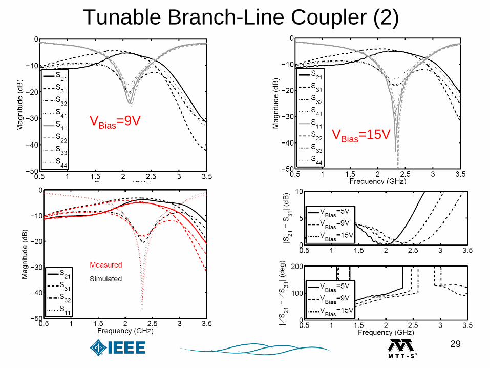
VBias=9VVBias=15V
Tunable Branch-Line Coupler (2)
29

• Tuning range 1.8-
2.3GHz
• IL < 2.7dB, RL > 15dB
• Amplitude error < 0.4dB
• Phase error < 5deg
Tunable Branch-Line Coupler (3)
30
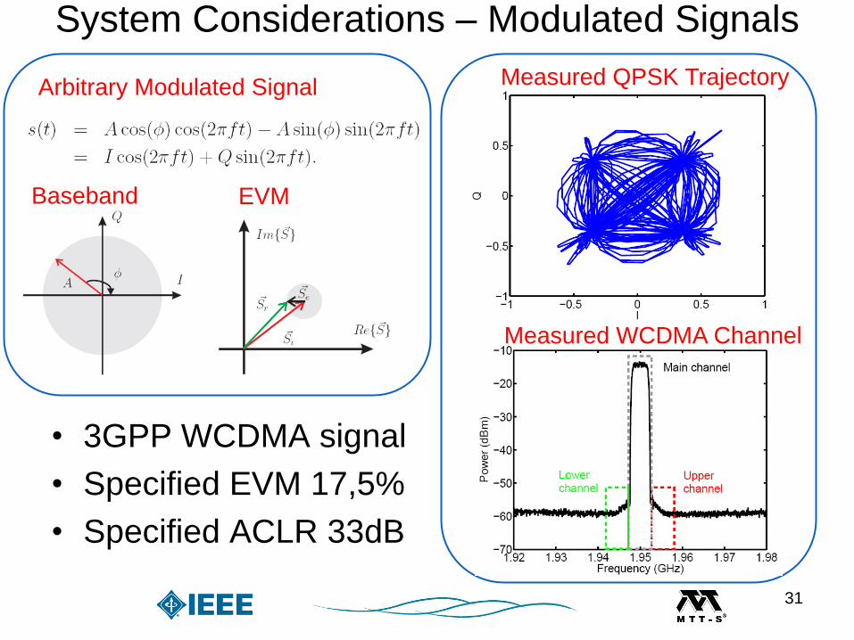
System Considerations – Modulated Signals
• 3GPP WCDMA signal
• Specified EVM 17,5%
• Specified ACLR 33dB
Arbitrary Modulated Signal
Baseband EVM
Measured QPSK Trajectory
Measured WCDMA Channel
31

System – Balanced Amplifier
Voltage waveforms at Pin=0dBm
Pin=0dBm
Operating at transmit band f=1.95 GHz
32

System – Reconfigurable Balanced Amplifier (1)
• Size reduction 50%
• Lowpass filtering
• Increased loss
• Bias voltage 5V
• Strong nonlinearities due
to BST-varactors
roll-off
Operating at transmit band f=1.95 GHz
33

• Distortion at voltage
waveforms
• Performance still within
specification
• Simulated EVM < 10%
• Simulated ACLR ~ 35dB
Operating at transmit band f=1.95 GHz Pin=0dBm
System – Reconfigurable Balanced Amplifier (2)
34

Tunable coupler with 3 cascaded varactors
Operating at transmit band f=1.95 GHz
Pin=0dBm Pin=0dBm
3 cascaded varactors
35

Verification – Tunable Branch-Line Coupler
Pin=10dBm
Agilent PSG
Agilent PSA
Pin=10dBm
36

Conclusion & OutlookConclusion
• Potential of ferroelectrics in tunable front-end
• Reliable modeling and characterization
• Candidates for tunable microwave circuits
– Frequency agile filters
– Reduced size tunable dividers and couplers
• Prototype implementation & results
• Overall good agreement to simulation
Outlook
• Integration of tunable subsystems into front-end
37