French B Line by Eaton
59
French Gerleman Expo B‐Line by Eaton Matthew T Combes Midwest Sales Engineer
Transcript of French B Line by Eaton

French Gerleman ExpoB‐Line by Eaton
Matthew T CombesMidwest Sales Engineer

Today’s Topics• New Cable Tray Solutions• New Strut Solutions• Structural Steel Savings

KwikSplice™ Cable Tray Solutions

KwikSplice™ Product OverviewProduct Features & Benefits• Five new profiles
– NEMA 12A ‐ CSA class C‐3m (4” and 5” side rails)– NEMA 12B ‐ CSA class D‐3m (4”, 5”, and 6” side rails)
• Innovative, industry leading two‐bolt splice connection
• Breadth includes straights, fittings, and tool less accessories
• 6063 marine grade aluminum• NEMA 12A and 12B load classes• CSA Class C and D (3m) load classes• I‐Beam configuration for side rail and rung• Focused around labor savings and ease of
installation
Tab and Lock Trapeze
Engineered Design that Delivers Labor & Material SavingsCable Exit Options Designed to Protect All Types of Cable
Universal Fitting
Splice Retention Groove

Benefits and Features• I‐Beam Construction
– Side rails and rungs– High strength to weight ratio
• 6063‐T6 marine grade aluminum
• Patent pending splice retention groove allows for a two‐bolt splice connection
• Maintains structural integrity of cable tray system
• UL Classified
Up to 50% Labor Savings at Splice Locations

Universal Fitting
• UL classified• Stocked• Tool less splice engagement
with fitting• Hole accommodations in
bottom plate for width reduction and securing cables.
• Accommodates both Redi‐Rail™ and KwikSplice™ cable tray systems
• All‐In‐One horizontal fitting• Shipped as a horizontal bend• Remove one side panel – horizontal tee• Remove two side panels – horizontal cross

Universal Fitting ‐ Corner Post
See Section B.2 of PROLaunch assessment
• 2” outside smooth radius with two screw ports.• Tool less rotating hinge feature eliminates need for splice plate
hardware.• Capture slots on each side to hold side panel.
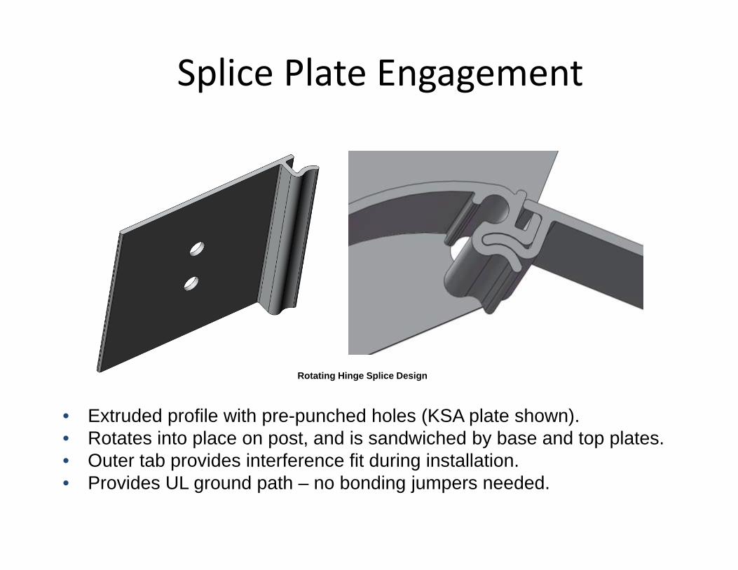
Splice Plate Engagement
See Section B.2 of PROLaunch assessment
• Extruded profile with pre-punched holes (KSA plate shown).• Rotates into place on post, and is sandwiched by base and top plates.• Outer tab provides interference fit during installation.• Provides UL ground path – no bonding jumpers needed.
Rotating Hinge Splice Design

Accessories – Features and Benefits Vertical Conduit Hanger
– Load rating: 75 lbs.– Fastens to underside of run using (2) BAX‐4‐16– Slotted for adjustment between rungs.
Trapeze Hanger– Innovative tab and lock design
• Simple installation with flat head screw driver• Allows for pre‐installed or post installed supports• Eliminates the need for hold down clamps
– Accommodates 3/8” standard hardware –OR‐Buzznut™
– Standard widths available: 6” ‐ 36”
Side Rail Waterfall Dropout– Hook and snap design with punched end for
cable ties.– 4” outside radius to protect bend radius of
cable– Offered in 6”, 12” and 18” lengths.

vs
WirebasketKwikSplice™KwikSplice vs Wirebasket
Focusing on Lowest Total Installed Cost Solution

WirebasketKwikSplice
Tab and Lock Trapeze Hanger 1/4” & 3/8” ATR 10ft or 12ft spans Built in Hold Down Tabs Future multi‐tier expansion capability
Trapeze Hanger 1/4” & 3/8” ATR 5ft or 6ft spans
Supports

WirebasketKwikSplice
Standard Splice Plate ¼” hardware Included in cable tray cost
WASHER SPL KIT ¼” hardware Sold separately
Splicing

WirebasketKwikSplice
Standard Splice Plate 4” X 24” – 2 cuts NEMA 4.5.2 – circular saw or
band saw
Clean Shear 4” X 24” – 18 cuts NEMA 4.5.2 – Offset bolt
cutters
Field Cuts

WirebasketKwikSplice
Universal Fitting All in one fitting (HB, HT, HX) 0 cuts Integrated splices 2” smooth radius
Bolt Cutter Horizontal bend 4” X 24”
Hard bend – 30 cuts Radiused – 330 cuts
3‐12 splices Sharp corners created
Fitting Fabrication

Bolted Framing
4D ™ Bolted Framing Solutions
Eaton-BLine-4Dimension.mp4
Contractor NameContact NamePhone #E‐MailProject NameProject LocationStrut UsedDistributor Distributor Location
PLEASE ATTACH INVOICE


Bolted Framing
Structural Steel Savings

NEMA VE‐2:General “How‐to” guidePrescribes methods for proper handling, storage, and installation of the cable tray.
Guidelines for proper support locations
“The support span should not be greater than the straight section length, or as recommended by the manufacturer, to ensure no more than one splice is located between supports.”

Steel Cable Tray Supports
Supports Can Be a Significant Cost
Trapeze Support$75 ‐ $250/support
Engineered Pipe Racks$1,500 ‐ $15,000/support

Current State – Standard Fitting Supports
Design Driven by NEMA VE‐2 ‐ Supports

Why the “Current State?”• NEMA VE 2 supplies recommendations for the installation of cable tray
including support locations for fittings

How B‐Line Can Help
Minimize Required Steel for Fittings

B‐Line Recommended Support Locations
• B‐Line fitting support spans exceed NEMA VE‐2
• B‐Line requirements provide more flexibility in the field
• Fewer supports decreases project cost –materials and labor
• Tested to NEMA 20C

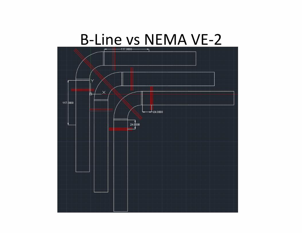
B‐Line vs NEMA VE‐2• NEMA VE‐2 allows for manufacturers recommendations for location of
supports– Fitting Support Locations NEMA VE‐2 4.4.1:
• “…unless otherwise recommended by the manufacturer…”
B-LineNEMA VE-2
Added Flexibility for Horizontal Fittings

B‐Line vs NEMA VE‐2
B-LineNEMA VE-2
Support within 2’, 24” Radius Max

B‐Line vs NEMA VE‐2
NEMA VE-2
B-Line
Added Flexibility for Vertical Fittings
B‐Line vs NEMA VE‐2

B‐Line vs NEMA VE‐2

Some Math…• Horizontal Fitting Example
– Steel weighs ~31lb/ft– Opportunity to reduce ~40’ of steel
– Results in ~1240lbs of steel removed
– How many times can this be repeated??
B‐Line reduces structural steel and labor to install it!!

Analysis Cost Summary• B‐Line’s analysis of large EPC project BOM shows the following
cost savings based upon $175/support
Solution Cost Savings– Fitting Support Solutions: $1,220,625.00
TOTAL SAVINGS: $1,220,625.00

TangentsMinimal Contact
for Splices
Or Curved Splices
Maximizes Splice Contact Surface Area
Maximizes Splice Contact
34

Additional Savings Opportunities• Longer spans of Tray
– 30 and 40 foot lengths• 57A, S8A
• Reducing # of supports with longer span reduces overall cost
– As distance increases, savings increase

Long Span Trays cost savings Example
Savings greater than total cable tray cost!!!
20 to 30' comparison
Cable TrayCatalog Number List Price Run Length Tray List Total
46A09‐24‐240 $ 641.00 ea 1300' $ 41,665.00
57A09‐24‐360 $ 1678.00 ea 1300' $ 72,154.00
Tray Difference $ 30,489.00
Supports# of Supports Support Price @ $3,000.00 Support Price @ $6,000.00
65 @ 20'$3,000
$ 195,000.00 $6,000
$ 390,000.00
43 @ 30' $ 129,000.00 $ 258,000.00
SavingsSupport Difference $ 66,000.00 $ 132,000.00
Tray Difference $ ‐30,489.00 $ ‐30,489.00
Total Savings $ 35,511.00 $ 101,511.00

Typical 6M Pipe Rack
6m 6m 6m 6m
1.5m
Typ.
LadderPipe Rack Structure can be eliminated on 50%
3m 3m 3m 3m 3m 3m3m 3m
1m
Typ.
Ladder Pipe RackStructure
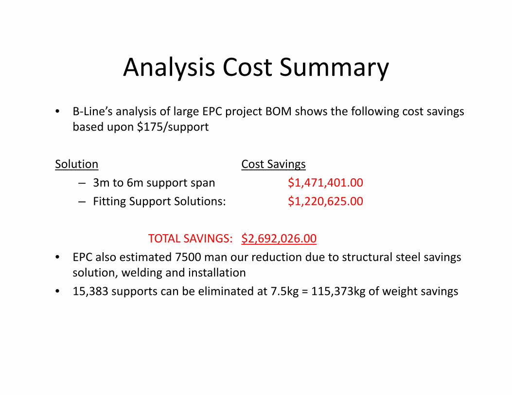
Analysis Cost Summary• B‐Line’s analysis of large EPC project BOM shows the following cost savings
based upon $175/support
Solution Cost Savings– 3m to 6m support span $1,471,401.00– Fitting Support Solutions: $1,220,625.00
TOTAL SAVINGS: $2,692,026.00• EPC also estimated 7500 man our reduction due to structural steel savings
solution, welding and installation• 15,383 supports can be eliminated at 7.5kg = 115,373kg of weight savings

Straight Run Supports• NEMA VE‐1 load test
• NEMA VE‐2 and B‐Line recommend placing splices at ¼ span to decrease deflection

B‐Line and NEMA Recommendation
• Splice plate at ¼ span• Reduces deflection up to 50%• Increases rigidity of system
Best Installation for tray – not always for project

Splice located on supports – Simple Beam
• Standard splice plates and expansion splice plates on support
• Eases design criteria• Potential for MAXIMUM DEFLECTION
More common actual installation practice than ¼ span

Current State ‐ Expansion/Contraction
• NEMA VE‐2 Section 4.3.2 requires supports within 2’ on both sides of an expansion splice
Splice often on support to satisfy NEMA for expansion

Splicing on Supports• Splicing on supports
creates issues– Simple beam – max
deflection due to max positive moment at support location
– Potential for guide and splice hardware interference

Current State – Splicing Long Runs
• Environmental– Expansion/Contraction concerns
• Performance– Deflection
Outdoor applications present significant challenges

• Expansion and contraction must be accounted for– Vertical Runs– Long Horizontal Runs

Possible Expansion Splice Plate Installation Issue

NEMA VE‐2 Recommendation• Splice Location
– ¼ span• Aesthetics
– Minimum Deflection– Reduced ~50%
• NEMA 4.3.2– Support within 2’ of expansion splice
StandardSplice Plate
Support
Cable Tray
¼ Span
¼ Span
ExpansionSplice Plate
2 Ft
Adds cost!

B‐Line Solution• Minimize structural supports
– Reduced required supports and allowed flexibility at fitting locations
• Minimize deflection– All Splices can be located at ¼ span
• Increase system flexibility with a lower overall installed cost Heavy Duty
Expansion Splice
20 ‘20 ‘
Expansion Splice Plate
5'

NEMA VE 2 vs. B-Line Recommendation
NEMA VE 2 B‐Line

Heavy DutyExpansion Splice
B‐Line Solution
NOW Available in both Aluminum and (HDG and Stainless) Steel versions!
HD Exp Splice Lowers Total Project Cost!

System Improvement with Reduced Total Installed Cost
• Performance– Min Deflection– Reduced ~50%
• NEMA 4.3.2 – HD Expansion Splice Plate
– Maintains ¼ span splice locations– No additional supports required
• Longer Spans – Cost Savings Increase as Cost/Support
increases
• Fitting Support Locations– Added Flexibility – Reduced Design Time– Reduced Materials/Labor

B‐Line I‐Beam Advantages
• 1. I‐Beam side rail design• 2. Added material to top flange
– Strengthens failure point
• 3. Welding bead/top rung lock• 4. Bottom inside flange/rung support• 5. Additional material to bottom flange
1
2
34
5
5
2
1
34

B‐Line I‐Beam Advantages
• Superior load carrying versus C‐ChannelC‐section side rail profile:‐ 6” high x 16ga side rail‐ 86lbs/ft on a 12’ span
I‐beam side rail profile:‐ 6” high x 16ga side rail‐ 208lbs/ft on a 12’ span

How Can B‐Line Do This…?• Material (aluminum)
• I‐beam siderail
• Wedge‐Lock Splice
• Specialty Splice (HD Exp)
• Fitting design (I‐beam, tangents)
5 Reasons – 1 System – Max Savings

Project Example – Ethanol Facility• 12” – 1,400 ft• 24” – 13,000 ft• 36” – 1,500 ft
24” TrayHorizontal Bends 67Horizontal Tees 10Horizontal Crosses 0Vertical Bends 141
Assumptions1) Individual Support Cost $1,0002) Fitting/Intermediate Support Cost $5003) Temperature differential of 1000 F (65ft expansion spacing)

Closing Discussions• Recap• When do these concepts need to be applied?• What can we provide
– Calculators• Thoughts, criticisms? • Where do we go from here?
B‐Line Saves Time & Money
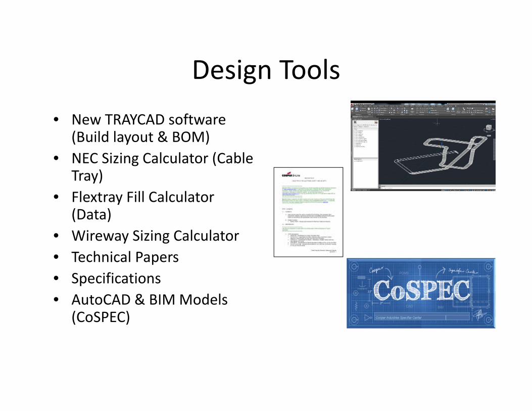
Design Tools• New TRAYCAD software
(Build layout & BOM)• NEC Sizing Calculator (Cable
Tray)• Flextray Fill Calculator
(Data)• Wireway Sizing Calculator• Technical Papers• Specifications• AutoCAD & BIM Models
(CoSPEC)

CoSpec ‐ Demo
58