Freeze Casting – A Review of Processing, … · be tuned during the solidification process. The...
143
Accepted Manuscript Freeze Casting – A Review of Processing, Microstructure and Properties via the Open Data Repository, FreezeCasting.net Kristen L. Scotti, David C. Dunand PII: S0079-6425(18)30001-X DOI: https://doi.org/10.1016/j.pmatsci.2018.01.001 Reference: JPMS 487 To appear in: Progress in Materials Science Received Date: 19 September 2017 Revised Date: 26 December 2017 Accepted Date: 5 January 2018 Please cite this article as: Scotti, K.L., Dunand, D.C., Freeze Casting – A Review of Processing, Microstructure and Properties via the Open Data Repository, FreezeCasting.net, Progress in Materials Science (2018), doi: https:// doi.org/10.1016/j.pmatsci.2018.01.001 This is a PDF file of an unedited manuscript that has been accepted for publication. As a service to our customers we are providing this early version of the manuscript. The manuscript will undergo copyediting, typesetting, and review of the resulting proof before it is published in its final form. Please note that during the production process errors may be discovered which could affect the content, and all legal disclaimers that apply to the journal pertain.
Transcript of Freeze Casting – A Review of Processing, … · be tuned during the solidification process. The...
Accepted Manuscript
Freeze Casting – A Review of Processing, Microstructure and Properties via theOpen Data Repository, FreezeCasting.net
Kristen L. Scotti, David C. Dunand
PII: S0079-6425(18)30001-XDOI: https://doi.org/10.1016/j.pmatsci.2018.01.001Reference: JPMS 487
To appear in: Progress in Materials Science
Received Date: 19 September 2017Revised Date: 26 December 2017Accepted Date: 5 January 2018
Please cite this article as: Scotti, K.L., Dunand, D.C., Freeze Casting – A Review of Processing, Microstructure andProperties via the Open Data Repository, FreezeCasting.net, Progress in Materials Science (2018), doi: https://doi.org/10.1016/j.pmatsci.2018.01.001
This is a PDF file of an unedited manuscript that has been accepted for publication. As a service to our customerswe are providing this early version of the manuscript. The manuscript will undergo copyediting, typesetting, andreview of the resulting proof before it is published in its final form. Please note that during the production processerrors may be discovered which could affect the content, and all legal disclaimers that apply to the journal pertain.

1
Freeze Casting – A Review of Processing, Microstructure and Properties via the Open Data
Repository, FreezeCasting.net
Kristen L. Scotti1 and David C. Dunand
*1
1Department of Materials Science and Engineering, Northwestern University, Evanston, IL
60208, USA
Abstract
Freeze-casting produces materials with complex, three-dimensional pore structures which may
be tuned during the solidification process. The range of potential applications of freeze-cast
materials is vast, and includes: structural materials, biomaterials, filtration membranes,
pharmaceuticals, and foodstuffs. Fabrication of materials with application-specific
microstructures is possible via freeze casting, however, the templating process is highly complex
and the underlying principles are only partially understood. Here, we report the creation of a
freeze-casting experimental data repository, which contains data extracted from ~800 different
freeze-casting papers (as of August 2017). These data pertain to variables that link processing
conditions to microstructural characteristics, and finally, mechanical properties. The aim of this
work is to facilitate broad dissemination of relevant data to freeze-casting researchers, promote
better informed experimental design, and encourage modeling efforts that relate processing
conditions to microstructure formation and material properties. An initial, systematic analysis of
these data is provided and key processing-structure-property relationships posited in the freeze-
casting literature are discussed and tested against the database. Tools for data visualization and
exploration available through the web interface are also provided.
Keywords: ice-templating, solidification, porous materials, mechanical properties, data
repository
* Corresponding author. Tel.: +1 847 491 5370. Fax: +1 847 467 6573 E-mail address: [email protected] (D.C. Dunand)

2
1. Introduction
Freeze-casting is a solidification technique for fabricating porous materials. During solidification
of a suspension or solution, walls are templated due to the rejection of particles and/or solute by
a solidifying fluid. Pore structures, which are created after post-solidification solid removal,
replicate the morphology of the solidified fluid. Freeze-casting gained much of its initial
attention in the early 2000’s as a processing route for polymer [1-4] and ceramic [5]
biomaterials. Concurrent investigations of freeze-cast materials for other ceramic-based
applications, including filtration membranes [6-8] and fuel cell electrodes [9-16], began to reveal
the true versatility of the technique. Freeze-casting of metals [17], pharmaceuticals [18-24], and
foodstuffs [25] was demonstrated within the same decade. From the early 2000’s to 2017, the
number and diversity of potential applications for these materials grew considerably;
applications investigated include substrates for supercapacitors [26-32], photocatalysis [33-43],
liquid chromatography [44], sensors (e.g. pressure [45-47], biological [48] and gas [49-51]), and
batteries [52-63]; biomaterials [64-106] remain the most extensively investigated application.
Dense composite materials may also be fabricated by infiltrating freeze-cast skeletons with a
secondary phase. Thus far, ceramic/metal [52, 107-120], ceramic/polymer [121-139],
metal/polymer [140-144], and metal/metal [145, 146] composites have been demonstrated.
The flexibility of the freeze-casting process is an advantage of the technique. The volume
fraction, size, shape, and orientation of porosity templated during the process may be tuned by
changing suspension characteristics (e.g. fluid type [147], additives [148], particle fraction [149])
as well as solidification conditions (e.g. solidification technique [150], freezing substrate
temperature [151], mold design [152, 153] and freezing substrate material [154]). However, this
freedom also adds significant complexity when attempting to understand the underlying
principles that govern the microstructure templated during the process. By the end of 2016, ~900
papers (Fig. 1) had been published on the freeze-casting technique, most of them since 2006;
over 800 of these papers represent independent experimental investigations. Each study
presents—to some degree—its own set of parameters, so that drawing conclusions from any one
paper is nearly impossible and systematic review of processing-structure-property relationships
is difficult. Although we have a basic understanding of the underlying principles that govern
microstructure formation during solidification, new parameters thought to influence these
principles are still being identified (e.g., surface wetting of the freezing substrate [153] and filler
material [155], coarsening [156], mold design [152], and gravity [157]); new models are also
being applied to describe resulting, anisotropic properties [158].
Here, we expand upon the initial meta-analysis of Deville et al. published in 2016 [159], with the
creation of a freeze-casting experimental data repository. As of August 1, 2017, the repository
contains data extracted from over 800 different freeze-casting papers (consisting of over 6,000
unique experimental specimens which total over 10,000 samples). These data pertain to variables
that link processing conditions to microstructural characteristics, and finally, mechanical and
physical properties. The aim of the database (and this paper) is to facilitate broad dissemination
of relevant data to freeze-casting researchers and users, promote better informed experimental
design, and encourage modeling efforts that relate processing conditions to microstructure
formation and material properties. To that end, the freeze-casting database is provided free to the
public through a web interface (http://www.freezecasting.net), under a Creative Commons
ShareAlike license.

3
As an introduction to the FreezeCasting.net database, we summarize microstructural
characteristics observed in freeze-cast materials and test key processing-structure-property
relationships posited in the freeze-casting literature against the FreezeCasting.net database.
General freeze-casting principles are reviewed briefly in the following; these are discussed in
greater detail elsewhere (basic freeze-casting principles [3, 160-169], processing-structure-
properties relationships [5, 161, 168, 170-174], and broader relevance of the technique [175,
176]). In comparison to previous reviews, we also provide more granular data analysis by
making distinctions between (i) solidified, unsintered and sintered samples, (ii) anisotropic and
isotropic structures, and (iii) ceramics, metals, and polymers. We also include ~500 additional
papers since the latest meta-analysis. All data figures were created using a Python/Jupyter
notebook and data contained within the FreezeCasting.net database, as of August 1, 2017. The
corresponding notebook and database are available for download from the FreezeCasting.net
website (http://www.freezecasting.net/downloads; Creative Commons ShareAlike license).
1.1. Basic principles
1.1.1. Anisotropic vs. isotropic freezing
Freeze-casting solidification techniques can broadly be categorized as “anisotropic” or
“isotropic.” Anisotropic, usually “unidirectional”, techniques are more extensively investigated
than isotropic techniques. This process is depicted in Fig. 2. First, (a) a suspension of particles or
a solution containing dissolved polymer is placed into a mold. Typically, the mold is composed
of thermally insulating sides (e.g., Teflon) and a thermally conductive base (e.g., copper). The
base of the mold is cooled, promoting (b) nucleation and directional propagation of a
solidification front. At first, the solidification velocity is very high and suspended particles
(and/or solute) are initially engulfed by the solidification front. This results in a dense particle
layer at the base of the sample [3, 177, 178]. The latent heat released by this early freezing event
slows the solidification velocity and particles are subsequently pushed by the solidification front
rather than engulfed, forming a (c) particle/solute accumulation region ahead of the front [179,
180]. As solidification progresses, rejected particles and/or solute are concentrated within
interdendritic space, where solidification of interstitial fluid eventually occurs as well. Once (d)
solidification is complete, the solidified fluid is (e) removed via sublimation, and in the case of
ceramic and metal material processing, (f) the resulting scaffold is sintered to densify particle-
packed walls. The pore morphology in the final material is a near replica of the morphology of
the solidified fluid, and shows both a vertically-aligned, elongated structure and horizontal
orientational alignment within colonies.
For anisotropic freeze-casting, solidification typically takes place vertically, from the bottom to
the top (hereinafter, referred to as “unidirectional solidification”), as depicted in Fig. 2.
Demonstrated solidification heights for this configuration range from 100 μm [181], using a
combined doctor-blade/freeze-casting technique, to 9 cm [182] via traditional methods as
described above. Sample areas as large as 38 x 15 cm [183] have been demonstrated via
unidirectional freeze-tape-casting [183-189]. Anisotropic radial freeze-casting is also employed.
In this case, the top and base of the mold are composed of thermally insulating material and,
either the sides, or a rod placed in the center, of the mold is thermally conductive. When cooled,
solidification is initiated at either the perimeter [9, 190, 191] or center [70, 192] of the
suspension, and the resulting front propagates horizontally, in a radial manner.

4
Isotropic freeze-casting techniques were demonstrated as early as 1954 [193] and are still used
today for the production of non-aligned porosity [194]. This process is depicted in Fig. 3. A
suspension contained within a thermally insulating mold is (a) placed in a freezer, and (b) solid
nucleation occurs randomly throughout the suspension. After nucleation, (c) solid crystal growth
occurs at random orientations; a preferential growth direction is not observed. After (d)
sublimation and (e) sintering, the resulting pore structures are nearly isotropic [195-197].
Depending on the isotropic technique employed, pore structures range from closed, equiaxed
cells (when isotropic freezing and space-holder techniques are combined [198]) to open, reticular
[199] networks. In some cases, thermally conductive molds are used and freezing progresses
directionally from the bottom as well as radially from the sides [200]. Although some
microstructural directionality is often observed in the resulting material (especially radially and
at the bottom), overall, the structure is nearly isotropic. Isotropic freeze-casting techniques are
most commonly used for freeze-gelation; in such cases, the precursor suspension or solution
undergoes a gelling or cross-linking stage prior to freezing [201-204]. Unidirectional freeze-
gelation techniques have also been demonstrated [205-217].
1.1.2. Pore structures
The microstructures of freeze-cast materials are qualitatively described in terms of their pore
structure, with the most commonly reported anisotropic pore structures being lamellar (60%),
dendritic (20%), and honeycomb (19%). Anisotropic columnar [218-221], needle-like [222,
223], and fishbone [224] morphologies have also been demonstrated. For isotropic structures,
cellular (92%) and equiaxed (7%) structures predominate. A schematic representation of these
pore structures is shown in Fig. 4, though as discussed in Section 3.1, considerable variation
within these structures is observed. Nevertheless, for the purposes of drawing processing-
structure-property connections, pore structures are categorized as shown in Fig. 4 and defined as
follows: Anisotropic lamellar structures (Fig. 4-a) exhibit plate-like walls which align parallel to
the freezing direction. Lamellar walls often exhibit dendritic features ranging from surface
roughness [148] to secondary dendritic arms [151]. As shown in Fig. 4(b), dendritic structures
exhibit primary trunks (“primary arms”) and tree-like branching, commonly referred to as
secondary arms. When anisotropic freeze-casting techniques are employed, honeycomb
structures are elongated hexagonal structures [225], as shown in Fig. 4(c); these may also present
as elongated tubes [226]. Prismatic cells [227] result when non-directional, freeze-gel-casting
techniques are used (Fig. 4-d). These prismatic cells are relatively uncommon; thus, we refer to
the elongated honeycomb structures shown in Fig. 4(c) as “honeycomb” throughout. Lastly,
near-isotropic structures of closed, equiaxed cells [198] and open, reticular-cellular networks
[228] are shown in Fig. 4(e) and (f), respectively.
Quantitatively, freeze-cast microstructures are most commonly described in terms of total
porosity, structure wavelength, and pore and wall sizes. Structure wavelength, is defined as the
average sum of the width of one pore plus its adjacent wall [151]. This parameter, traditionally
used to describe primary dendrite spacing in metal alloys [229], only applies to anisotropic
freeze-cast materials and is most commonly used to describe lamellar structures. For dendritic
structures, primary [230] and secondary dendrite spacing [231] (the distance between secondary
arms) are less often reported. For anisotropic microstructures, pore and wall size is typically
described in terms of width (the length of the minor axis), whereas for isotropic structures,
diameter is used.
1.1.3. Characterization methods
5
Microstructural characteristics of freeze-cast materials are primarily determined during
solidification. The morphological evolution of the solidification front is highly dynamic;
processing-structure relationships are complex and incompletely understood. Our current
understanding is largely influenced by experimental investigations of sintered samples.
Microstructural characteristics of sintered samples are most often quantified using two-
dimensional images obtained using optical and scanning electron microscopy techniques. Two
main issues exist in attempting to discern processing-structure relationships using these data.
First, data obtained from two-dimensional images may not reflect the true, three-dimensional
structure of these materials. Second, microstructures templated during the solidification process
are often modified as a result of subsequent sublimation [232] and sintering [233] steps.
Fife et al. [234] compared measurements of pore width obtained using three-dimensional X-ray
tomography reconstructions and two-dimensional optical micrographs of unidirectionally freeze-
casted titanium materials. Data corresponding to mean pore width obtained from optical
micrographs were 5-45% higher than corresponding values of inverse surface area per unit
volume (related to the two-dimensional measurement of pore width) obtained from three-
dimensional reconstructions. In addition to providing a more accurate representation of feature
sizes, three-dimensional reconstructions allow for quantification of parameters such as
interconnectivity, percolation, surface curvature and tortuosity [230, 235-237]. These are
important parameters for many freeze-cast material applications (e.g., filters; fuel and solar cell
electrodes), but are rarely reported, as they are intrinsically three-dimensional properties and
often inaccessible to two-dimensional measurements.
The first attempts to address confounding effects of post-solidification processing on freeze-cast
microstructures focused on utilizing green (sublimated, but unsintered) samples infiltrated with
epoxy [238-240]. Although this approach mitigates any sintering shrinkage effects,
microstructural effects of sublimation (such as local particle rearrangement as well as warping or
cracking of the green body) remain unaccounted for. It is also unknown whether, or to what
extent, infiltrating these fragile compacts with epoxy might introduce additional changes. Later
attempts to account for post-solidification processing effects utilized rates of linear sintering
shrinkage as a back-estimate of pre-sintering microstructural feature sizes [241]. This approach
assumes that sintering shrinkage is near-isotropic; for anisotropic pore structures, this is not
necessarily the case [242]. Deville et al. [243-246] published a series of papers which provided
the first experimental data obtained during in-situ investigation of the freeze-casting
solidification process. These and subsequent in-situ investigations [207, 247-263] have provided
better insight into the principles that underlie the templating process during solidification.
Undoubtedly, in-situ investigations of the solidification process, combined with 3D
reconstruction comparisons of frozen, not-yet-sublimated freeze-cast samples and sintered
samples, hold great promise in clarifying processing-structure-property relationships. Few
investigations of this nature have been published [179, 264], therefore, we attempt to clarify
these relationships using data obtained for a variety of samples at various processing steps. This
effort is facilitated by categorical designations within the FreezeCasting.net database where
microstructural and mechanical data correspond to that obtained from (i) in-situ investigations,
(ii) solidified, not-yet-sublimated samples, (iii) sublimated, not-yet-sintered samples, and (iv)
sintered samples, are designated as “solidification”, “frozen”, “green”, and “sintered”,
respectively. These conventions are utilized throughout.
6
2. Methods
2.1. Systematic literature review
A systematic literature search was conducted to identify papers published between the years
1998 and 2017. Two strategies were employed to identify relevant literature. First, computer
searches were performed on Google Scholar and Web of Science utilizing the search terms:
“freeze-casting” OR “freeze-cast” OR “ice-templating” OR “ice-template” OR “ice segregation
induced self-assembly” OR “unidirectional freeze-drying” OR “freeze-gelation” OR “gel-
casting” OR “phase separation method.” Second, sources cited in relevant literature obtained
from the first step were manually checked; relevant literature was added to the database and
associated references were also checked and added when appropriate.
Overall, these searches yielded over 2,000 keyword-related studies. Studies were then excluded
for any of the following reasons: (i) the technique did not involve a solidification step (e.g., “gel-
casting,” without freezing), (ii) the second phase was not sacrificial (e.g., traditional metal matrix
composites), or (iii) the primary materials produced were fibers and/or powders, rather than
porous scaffolds. Additionally, data pertaining to papers that: (i) were not available in the
English language (33 papers), (ii) did not contain data within the categories of interest (typically,
freeze-casting application papers reporting functional property data only; categories of interest
are defined in the following section), (iii) consisted of solely numerical (12 papers) and/or
theoretical analyses (12 papers), or (iv) review articles (43 papers), were added to a general
literature table only and data were not extracted. In the latter case, this was to prevent over-
representation of data subsets.
2.2. Data extraction
Data were manually extracted from included papers, preferentially from text and tables; data
were extracted from plots which were digitized using Plot Digitizer
(http://plotdigitizer.sourceforge.net) when values were not provided in text or tables. Unit
conversions were performed as needed. In particular, solid loadings were converted to volume
percent (vol.%) when provided in weight percent (wt.%) using, in order of preference: (1)
density of solid as provided in paper, (2) supplier data, or (3) reasonable estimates of density
using other literature sources.
2.3. FreezeCasting.net database
The FreezeCasting.net database was constructed using structured query language (SQL) and the
free, open-source relational database system, MySQL. However, the database may be used with
any SQL-compliant database system and additional file formats are available for download on
the FreezeCasting.net website (including: JSON, XML, and CSV).
2.3.1. Database architecture
A modified relational model was utilized in database design; the database schema consists of a
group of ‘primary’, ‘secondary’, ‘property’, and supplementary table(s). The primary group
serves as the backbone of the database. This group includes the tables named: (1) ‘authors’, (2)
‘papers’, and (3) ‘samples’. The secondary group consists of tables which hold all freeze-casting
experimental data; these tables are categorized by processing steps or characterization types.
Lastly, property tables provide property data for particles, fluids, molds, and bulk materials. As
of May 2017, the database contains one supplemental table (‘susp_stab’), which contains
experimental data relevant to suspension stabilization. This hierarchical approach circumvents

7
limitations of a preset number of columns in any particular table and provides flexibility to add
new variables of interest as well as supplemental tables without altering the overall database
schema.
It is expected that the majority of database users will work with the data using the web interface.
Therefore, priority was placed on efficiency over normalization during database design.
Although the majority of tables within the freezecasting.net database are in third normal form (in
terms of database normalization), exceptions, which serve to reduce required join operations, can
be found within secondary tables. A simplified depiction of the database schema is shown in Fig.
5; a full schema may be viewed/downloaded from the FreezeCasting.net website
(http://www.freezecasting.net/downloads).
2.3.1.1. Primary tables
Primary tables are shown in blue in Fig. 5. The ‘papers’ table contains relevant citation
information for each paper in the database. Each paper is classified by several categorical
designations. First, freeze-casting papers are distinguished from general suspension stabilization
papers by an ‘fc’ descriptor in the ‘category’ field (as opposed to ‘susp’ for suspension
stabilization papers). Papers which provide suspension stabilization data in the context of freeze-
casting work receive the hierarchical, ‘fc’ designation. Freeze-casting papers are further
categorized in the ‘subcategory’ field as experimental investigations (‘exp’), review articles
(‘review’), theoretical (‘theory’), and numerical (‘num’) analyses. Lastly, papers published in
peer-reviewed journals can be distinguished from non-peer-reviewed in the ‘peer_review’ field,
and open-access and publications holding Creative Commons licenses are designated within the
‘usage’ field. Each paper is linked to the corresponding author’s contact information through the
foreign key (in terms of database design, a foreign key is used to connect a row in one table with
a corresponding row in a different table), ‘author_ID,’ which is the primary key for the ‘authors’
table.
In most cases, individual papers report results that are obtained under varying processing
conditions, e.g., microstructural and/or mechanical properties obtained after sintering at different
temperatures while all other processing conditions (solid loading, cold plate temperature, etc.)
are held constant. For each of these cases, a unique ID number is assigned in the ‘samples’ table
(‘sample_id’). The primary key for the papers table (‘paper_id’) serves as a foreign key in the
‘samples’ table and links citation information to each sample. In turn, the sample ID acts as a
foreign key for each of the secondary tables such that row data may be appropriately linked.
2.3.1.2. Secondary tables
Processing-structure-property variables are grouped into secondary tables based mainly on
processing steps. These include, for example: suspension preparation, including suspension
constituents (e.g., particle, fluid, and additive types and concentrations), as well as suspension
characterization (e.g., viscosity, zeta potential, pH), solidification (e.g., technique, cooling rate,
cold plate temperature), sublimation (e.g., time, temperature, pressure), sintering (e.g., sintering
time, temperature, and heating/cooling rates), characterization (microstructure; e.g., pore and
wall width), and properties (mechanical; e.g., compressive strength). All secondary tables are
shown in green in Fig. 5.
2.3.2. User interface

8
The FreezeCasting.net data repository is provided to the public through a web interface
(http://www.freezecasting.net) to facilitate data exchange among researchers of the freeze-
casting community. The web interface offers three main features: (1) basic background
information about the freeze-casting technique, (2) downloadable formats of the database, and
(3) an interface for data exploration.
2.3.2.1. Data exploration and visualization
An interactive plotting application, developed using the JavaScript library, Data Driven
Documents (D3.js) [265], is provided on the FreezeCasting.net website
(http://freezecasting.net/plotting.html). A subset of 24 database variables (including those related
to suspension characteristics, solidification conditions, microstructure, and mechanical
properties) were selected for use in this application. Using D3.js, these data are bound to a
Document Object Model (DOM), and, upon user input, the document may be manipulated and
transformed based on the dataset that is bound to the DOM. The user may select any two of the
24 available variables to plot on the axes and filter results based on material group, material type,
and/or fluid type; each selection or filtration initiates a plot transformation. Additional
transformation options include coloring points based on fluid or material group, toggling
between linear and logarithmic axis scales, performing basic least square linear regressions, and
enabling “data point removal,” where plot points can be discarded by dragging the points off the
plot canvas. Citation data pertaining to each plot point are accessible via tooltip on mouse hover;
within the tooltip, an html link to the corresponding paper is also provided. Lastly, tables may be
generated based on filtered plot data and exported in CSV format.
An interactive table, featuring the same database subset as utilized in the interactive plotting
application, is also provided on the FreezeCasting.net website
(http://freezecasting.net/data.html). This application was developed using the DataTables [266,
267] plug-in for the JQuery [268], JavaScript library. The plug-in supports server-side processing
and, similar to the interactive plotting application, allows users to select variables for display in
the table and to export results.
2.4. Statistical analysis
Python was used for all statistical analyses; corresponding code is provided in the form of a
Jupyter notebook [269] using the IPython kernel [270] as a supplemental material. The Python
library, SciPy was used for linear [271] and non-linear [272] least squares curve fitting. Data are
expressed as mean, the standard deviation and median ( ). Logarithmic transforms were
performed on x and y arrays prior to performing curve fitting and/or regression analysis for
power law relationships. Paired t-tests were used to compare means of two groups; one-way
ANOVA and post hoc, paired t-tests with Bonferroni corrections were used to compare means
between more than two groups. A probability value of p < 0.05 was used to determine statistical
significance. Pearson correlation coefficients, hereinafter referred to as correlation coefficients,
or r were obtained using SciPy.
3. Processing-microstructure relationships
3.1. Templating pore structures using fluids and additives
For freeze-cast materials, pore structure is largely determined by the morphology of the
solidified fluid. Although most freeze-cast materials are fabricated using aqueous suspensions,

9
unique pore structures have been demonstrated using non-aqueous fluids as well (most
commonly, camphene [273-275] and tert-butyl alcohol (TBA) [276, 277]). Suspension additives,
such as dispersants and binders, are typically added to obtain well-dispersed suspensions and
increase green strength of sublimated specimens, respectively. However, recent work aims to
utilize these and other additives to tailor pore structures by manipulating freezing kinetics [231],
the crystalline structure of the solidified fluid [225], and/or modifying particle redistribution
behavior [278].
3.1.1. Aqueous processing
The choice of water as the fluid for freeze-casting is often attributed to its environmental
friendliness, low cost, and bio-inertness. An important, but often unnoted advantage of aqueous
processing routes is the large variety of attainable pore structures. When anisotropic freeze-
casting techniques are employed, the predominant pore structure is lamellar. These plate-like
structures predominate as a result of the anisotropic growth kinetics of hexagonal ice [279];
growth along the crystallographic c-axis (perpendicular to a vertically induced temperature
gradient) is 43-200% slower than that of the a-axis [280, 281]. Thus, growth of dendritic features
(i.e., ‘side-branching’ or ‘secondary arms’), which occur along the c-axis, are restricted for
hexagonal ice. As a result, these structures tend to exhibit high aspect ratios (defined as the ratio
of the length of the major pore axis to that of the minor). The mean aspect ratio calculated from
literature values for lamellar structures is 5.5±3.2 (N=212, [142, 218-220, 282-300]). High
aspect ratios are advantageous in applications such as batteries or heat exchangers, where open,
aligned channels facilitate fluid flow [301, 302]. However, for load-bearing applications,
increased interconnectivity between solid features is often desired as it improves the material’s
compressive response (e.g. by preventing internal wall buckling [148, 296, 303]). Wall
interconnectivity can be increased by inducing a morphological transition from lamellar to
dendritic structures during solidification. This is achievable by modifying suspension
characteristics (e.g. including additives such as binders [231, 304] or cryoprotectants [305] or
increasing particle volume fraction [306]) and/or solidification conditions (e.g. increasing
solidification velocity [3, 224, 307, 308]).
A schematic representation of the morphological transition of ice is shown in Fig. 6. In Fig. 6(a),
a lamellar morphology is depicted, and lamellae faces along the crystallographic a-axis are
perfectly flat. In reality, some dendritic features are almost always present. These typically
present in the form of secondary dendritic arm “stubs” which may appear on only one side of the
lamellae [151, 309]. The onset of dendritic side branching is depicted in Fig. 6(b); the secondary
arms increase in both length and area density (number of arms per unit area). In Fig. 6(c), the ice
morphology has completely transitioned from lamellar to dendritic. As side branching increases,
the diameter of the primary branch decreases. This reflects a decrease in the magnitude of
anisotropic growth between the a- and c-axes. Although the morphological structure of ice is still
dendritic in Fig. 6(d), the resulting porous structure is likely to be cellular because of the highly
interconnected ice network that has formed.
3.1.1.1. Binders
Microstructural changes resulting from a morphological transition during solidification from
lamellar to dendritic are shown in Fig. 7(a-d) for sintered Al2O3 [310]. Cross-sections are taken
parallel to the solidification direction; dark regions represent pores and the light regions are
sintered Al2O3 walls. Here, the dendritic transition is induced through the inclusion of increasing
10
concentrations of a binder, polyvinyl alcohol (PVA), to aqueous suspensions consisting of 25
vol.% Al2O3. Fig. 7(a) shows the microstructure obtained when no binder is added; the pore
morphology is lamellar and remnants of one-sided dendritic features are observed within the
walls. Microstructures obtained with the inclusion of 5, 15, and 20 wt.% PVA (with respect to
Al2O3) are shown in Fig. 7 (b) - (d), respectively. Secondary branching progressively increases
as the weight fraction of PVA increases and pore width decrease from ~25 μm at 0 wt.% PVA
(Fig. 7-a) to ~9 μm at 20 wt.% PVA (Fig. 7-d). Similar results were obtained when adding
increasing amounts of PVA to aqueous suspensions of 50 wt.% hydroxyapatite (HAP) [311],
23.5 vol.% Al2O3 [312], and 75 wt.% yttria-stabilized zirconia (YSZ) [313] powders, as well as
for polymers solutions (e.g. collagen and PVA [314]).
Fig. 7(e-i) shows a similar transition for tungsten disulfide (WS2) powder, where dendritic
morphologies are observed with the inclusion of increasing weight fractions of gelatin as a
binder [315, 316]. Again, cross-sections are taken parallel to the solidification direction,
however, the templated WS2 is sublimated but not sintered. The lamellar microstructure shown
in Fig. 7(e) is obtained with the inclusion of 1 wt.% gelatin (with respect to powder); the binder
content increases to 2, 3, 4, and 5 wt.% in Fig. 7 (f) -(i). As gelatin increases from 1 to 2 wt.%,
wall roughness increases (Fig. 7(f)); this indicates that secondary dendritic arms are likely
beginning to develop. Dendritic morphologies are observed in Fig. 7(g) and (h) and cellular
morphologies are observed with the inclusion of 5 wt.% gelatin (Fig. 8(i)). Similarly, dendritic
morphologies were reported in sintered hydroxyapatite (HAP) materials with the addition of 2-5
wt.% gelatin (with respect to powder) to aqueous suspensions containing 50 wt.% HAP; at 6
wt.% gelatin, a cellular morphology was also observed [317].
The transition from lamellar to dendritic morphologies due to the inclusion of binder is
commonly attributed to the increase in the suspension viscosity [312]. As suspension viscosity
increases, particle pushing by the advancing solidification front is inhibited due to increased
viscous drag. As a result, an increasing number of particles are engulfed by the growing solid.
Depletion flocculation may also play a role [318-320], which would also increase the number of
particles engulfed (since the size of aggregates increases). This explanation is more likely for
microstructural bridging between solid walls than a complete transformation to a dendritic ice
morphology. When large amounts of binder are added, constitutional undercooling must also be
considered. Although most binders are soluble in water, they have limited solubility in ice. Thus,
binder is rejected at the solid/liquid interface, its accumulation depresses the local equilibrium
liquidus temperature which, in turn, decreases the degree of undercooling and promotes
coarsening of secondary arms [310]. Similar lamellar to dendritic transitions were reported when
adding increasing amounts of PVA to aqueous suspensions with 50 wt.% hydroxyapatite (HAP)
[311] and 75 wt.% yttria-stabilized zirconia (YSZ) [313], as well as for ZrO2 with the addition of
30 wt.%, (with respect to dry particle mass) [321] of Na2SiO3 binder.
Sucrose was also observed to trigger a dendritic to cellular transition [148]; dendritic and cellular
structures were observed after anisotropic solidification of Al2O3 suspended in aqueous solutions
of citric acid containing 5 and 10 wt.% sucrose (with respect to dry powder mass), respectively,
as well with 8 wt.% trehalose, another sugar containing two glucose molecules. The addition of
sucrose introduces an interfacial instability within the solidification front which promotes side
branching during directional solidification [307]. Similar structures were obtained by Nguyen et
al. [322] for pharmaceutical tablets containing 20 wt.% sucrose (with respect to water) and for
cocoa tablets freeze-casted from aqueous suspensions containing up to 20 wt.% sugar alcohol

11
binders, including sucrose, isomalt and xylitol. The authors attribute the cellular pattern to a
decrease in the supersaturation of aqueous solution as a result of high binder content and a
concomitant decrease in the ice crystal growth rate, which resulted in smaller, spherical shaped
ice crystals.
3.1.1.2. Simple alcohols
The utilization of binary fluid systems consisting of water and simple alcohols (e.g. isopropyl
alcohol (IPA), ethanol, n-propanol) offers increased flexibility over the microstructural
interconnectivity, which can be tailored based on the employed alcohol concentration. For
example, the highest aspect ratio (defined above as the ratio of the length of the major pore axis
to that of the minor) from the literature comes from Naleway et al. [293] who demonstrated
increased aspect ratios using a binary fluid system consisting of IPA and water and a solid
loading of 10 vol.% ZrO2. The maximum aspect ratio of 20, corresponding to a pore width of 30
μm, was achieved using an IPA concentration of 5 vol.% (with respect to total fluid volume).
Comparatively, the authors report an aspect ratio of ~5 (pore width = 10 μm) without IPA. The
increase in pore width and aspect ratios due to inclusion of IPA is attributed to the formation of
clathrate hydrates during the freezing process [293, 296] and is shown to be maximized at 5
vol.% IPA. Above 5 vol.% IPA, pore width and aspect ratios decrease until 20 vol.% IPA is
reached, at which point, values similar to those obtained without IPA are reached [293, 296]. Fig.
8 shows similar results reported by Porter et al. [296] for 10 vol.% TiO2. These microstructural
cross-sections are taken parallel to the solidification direction; Fig. 8(a) shows the sintered TiO2
material obtained without IPA, and (b) - (d) show microstructures obtained with the addition of
1, 5, and 30 vol.% IPA (with respect to fluid volume). Pore aspect ratios are shown to be highest
(at ~10) with the inclusion of 5 vol.% IPA (Fig. 8-c), representing a three-fold increase from the
aspect ratio of ~3 reported without IPA (Fig. 8-a); the pore widths are also observably much
larger in Fig. 8(c) as compared to 8(a). However, with the addition of 30 vol.% IPA (Fig. 8-d),
microstructures more closely resemble those obtained without IPA.
The increase in both pore width and aspect ratio at relatively low fractions of IPA followed by a
subsequent decrease with increasing concentrations of IPA may be attributable to Ostwald
ripening (coarsening), where larger ice crystals increase in size at the expense of smaller ones.
The rate at which this occurs is strongly influenced by the type and concentration of solute;
relatively low concentrations of solute can increase the coarsening rate considerably [323].
However, at increasing concentrations of solute (in this case, IPA), mass transfer is increasingly
restricted and Ostwald ripening is impeded. This behavior can be exploited to increase
interconnectivity of the resulting solid microstructure. Similar behaviors are observed for other
alcohols, including ethanol [148, 291, 324], n-propanol [291], and n-butanol [291]. For 10 vol.%
ZrO2, aspect ratio enhancement is reported to peak at 10, 5, and 3 vol.%, respectively [291] for
ethanol, n-propanol, and n-butanol. A decrease in pore aspect ratios (i.e., increased
interconnectivity) is reported when ethanol is increased to 15-30 vol.% for Al2O3 [325] and 5-10
vol.% for Ti-6Al-4V [142]. Similarly, at 10-30 vol.% n-propanol in water, decreased aspect
ratios are observed for 10 vol.% Al2O3 [325].
3.1.1.3. Glycerol
Interconnectedness between lamellar walls may be also be increased with the inclusion of
glycerol as a suspension additive [285]. Microstructures consisting of lamellar walls joined by
bridges that form nearly perpendicular to, and join, the walls have been demonstrated using

12
aqueous suspensions containing 5 wt.% glycerol (with respect to water) [285]. The number
density of these bridges increases as the glycerol concentration increases [221, 286, 303, 305].
This transition is shown in Fig. 9, where the sintered lamellar structure shown in Fig. 9(a) were
fabricated via anisotropic solidification of aqueous suspensions of 10 vol.% HAP particles [286].
In Fig. 9(b), the concentration of glycerol in water increases to 20 wt.% glycerol. Similar to the
effect of PVA, the corresponding pore widths to decrease from 20-30 μm without glycerol to 1-
10 μm with glycerol. At high solid fractions (60 vol.% Al2O3), the addition of 20 wt.% glycerol
(with respect to water) reportedly results in a cellular microstructure [326].
Although glycerol is commonly employed in freeze-cast studies, the underlying mechanisms
governing its effect on suspension rheology and ice morphology during solidification are not
clearly understood. Solutions of glycerol and water exhibit higher viscosity than water alone
[327, 328] because glycerol is much more viscous than water, (~930 mPa·s [305] vs. ~0.9 mPa·s
for water). Thus, it has been suggested that the addition of glycerol increases the suspension
viscosity and restricts the diffusion of water molecules to the ice lattice [221]. Indeed, in some
cases, the addition of glycerol increases suspension viscosity [303, 329]. However, decreased
suspension viscosities have also been reported [305, 327, 330], especially at higher particle
volume fractions [305]. In each of these cases, the suspended particle is Al2O3 and the glycerol
contents are comparable (ranging from 10-30 wt.% with respect to water). It has also been
suggested that glycerol may interact with nonionic dispersants and reduce suspension viscosity
by forming micelles around particles [326, 331] or by untangling dispersant chains [327].
Lending support to this hypothesis, decreased zeta potential values have been reported with the
addition of glycerol for suspensions where decreased viscosity is also observed [326], whereas
for increased viscosity, zeta potential remains approximately the same [303]. However, glycerol
is reported to decrease pore width regardless of whether the suspension viscosity increased or
decreased as a result of its addition. This suggests that glycerol’s cryoprotectant properties are a
dominating factor in the reduction ice crystal size, rather than suspension viscosity.
It should also be noted that the addition of glycerol, both depresses the freezing point of the
suspension and decreases the volumetric expansion of water during freezing. At 10 wt.%
glycerol in water, the volumetric expansion of ice decreases from 9 to 7.4% [303], which is not
sufficient, by itself, for the reduction of pore sizes described above. However, inclusion of
glycerol might reduce the tendency for materials to develop ice-lens defects. These defects have
an appearance similar to that of frost heaves [332-336]. In sintered freeze-cast materials, ice
lenses are present as cracks perpendicular to the direction of solidification. Although not reported
specifically, ice lens defects appear to be present in Fig. 9(b) from ref. [337]. However, there is
no indication of ice lenses in any of the microstructure images after glycerol was added (e.g.,
Fig. 10 from ref. [337]). Decreased cracking has been reported with the inclusion of glycerol
[338] using isotropic freezing techniques.
3.1.1.4. Unique pore structures
Fig. 10(a) shows honeycomb structures achieved with the addition of a zirconium acetate
complex (ZRA) to an aqueous suspension of yttria-stabilized zirconia (YSZ) [225, 300, 339].
The versatility of this technique for modifying pore morphology has also been demonstrated for
Al2O3 [340, 341], SiC [225], and Teflon [225] freeze-cast structures, where particles are
suspended in an aqueous solutions containing 18 g/L of ZRA. Honeycomb structures may also
be obtained via freeze gel-casting techniques [342, 343]; the structure shown in Fig. 10(b) was
obtained for 5 wt.% gelatin scaffolds [282]. In this case, it is hypothesized that prior to freezing,
13
ice molecules from a discontinuous network throughout the gelatinous medium; thus, resulting
ice nuclei are segregated by the continuous, gelatin network. During solidification, growth of
secondary arms are restricted by the same gelatin network, resulting in columnar honeycomb
structures [343].
The equiaxed pore structures shown in Fig. 10(c) and (d) were both achieved by employing
isotropic freezing techniques. In Fig. 10(c), near spherical pores were obtained by subjecting
silica suspensions to a tumbling step prior to solidification. Air entrapped during the tumbling
step, and rejected during solidification, was responsible for the equiaxed macropores [198].
Similar structures can be obtained by adding polystyrene as a temporary space-holder, as shown
for the mullite foam depicted in Fig. 10(d) [344], or PMMA as a space-holder [345]. In these
cases, the space-holder templates the macroporosity, whereas the solidified fluid templates the
microporosity. In contrast, a combined unidirectional solidification and space-holder technique
was demonstrated for the fabrication of hydroxyapatite (HAP) materials [346, 347]. In this case,
macroporosity is templated by both the solidified fluid (water) and the pore forming agent, 5
vol.% hydrogen peroxide (H2O2); lamellar walls are separated by lamellar channels or by
lamellar arrays of spherical pores. At 9 vol.% H2O2, the lamellar pattern was lost and a cellular
structure resulted.
3.1.2. Non-aqueous processing
An overview of microstructures obtained using non-aqueous fluids and anisotropic freezing
techniques is shown in Fig. 11. Upon solidification, camphene forms isotropic, cubic crystals; as
growth of secondary arms is prevalent, the resulting pore structure is dendritic. This is illustrated
in Fig. 11(a) for sintered Al2O3 obtained after anisotropic solidification of 50 vol.% Al2O3
suspended in camphene [348]. The predominant structure for cyclohexane is also dendritic as
shown in Fig. 11(b) for sintered silicon oxycarbide (SiOC) [349]. This material was solidified
from a precursor solution of 20 wt.% preceramic polymer dissolved in cyclohexane. Lastly, the
dendritic structure shown in Fig. 11(c) is a polyurethane material templated using dioxane [181];
the precursor was also a solution.
An overview of honeycomb structures obtained via non-aqueous processing routes are shown in
Fig. 11(d-f). Fig. 11(d) is a polystyrene material obtained using 30 wt.% polystyrene dissolved in
a fluid system of 7-10 wt.% polyethylene glycol in dioxane [350]. A similar structure was
obtained by freeze gel-casting using a fluid system consisting of dodecanol-27 wt.% dioxane-23
wt.% triproplyene gycol-17 wt.% cyclohexanol and dissolved monomers, glycidyl methacrylate
(GMA) and ethylene glycol dimethacrylate (EDMA) [351]. TBA is, after water, the second most
commonly utilized fluid in the freeze-casting literature. When solidified unidirectionally, the
predominant structure is described as tubular, or elongated honeycombs; this is shown in Fig.
11(e) for sintered Al2O3-ZrO2 [352], the precursor suspension contained 10 vol.% particles
suspended in TBA. Dimethyl sulfoxide (DMSO) was utilized to obtain the honeycomb structure
shown in Fig. 11(f) for a poly (L-lactic acid; PLLA) material [353]; PLLA was dissolved in
DMSO prior to solidification.
3.2. Suspension stabilization
The first step in the freeze-casting process is to create a stable suspension. Particle-particle
interactions influence both particle packing behavior as well as the morphology of the solidified
fluid [318, 354]; unstable suspensions promote defect formation [278, 355], especially those
which may result from particle engulfment (e.g., ice lenses [159]). For suspensions containing

14
charged particles, the stabilization process can be non-trivial and often involves measuring zeta
potential (ζ) and viscosity for suspensions at various pH levels and at varying concentrations of
dispersants as well as other additives. The suspension stabilization table is included with the
FreezeCasting.net database to facilitate these efforts. As of August 1, 2017, the table contains
over 2,000 samples of viscosity and/or zeta potential data for suspensions containing 20 different
particle types.
An illustration of ζ data plots is provided in Fig. 12. Zeta potential quantifies the electrostatic
repulsion between particles within a suspension; at a higher magnitude of ζ, suspensions exhibit
greater stability. Therefore, a suspension can be stable at both positive and negative values of ζ.
Data were filtered to obtain only values for aqueous suspensions of aluminum oxide (Al2O3).
Filtered data of ζ are plotted against suspension pH in Fig. 12 [305, 354-368]. For these data, ζ is
positive at low pH values and decreases as the pH of the suspension increases. At the isoelectric
point (IEP) where ζ = 0, the suspension is very unstable (shown as a dashed red line in Fig. 8). A
stable suspension is broadly defined as one that exhibits a ζ magnitude of at least 30 mV [369].
Using this metric (ζ ≥ ±30 mV), an aqueous suspension of Al2O3 may be stable in the pH range
of 4-12, depending on the concentration and nature of the dispersant with respect to particle size
and volume fraction.
Dispersants are added to aqueous suspensions of charged particles (e.g., Al2O3) to protect against
flocculation and coagulation. Data points in Fig. 12(a) are mapped to their relative
concentrations of dispersant vs. zeta potential in Fig. 12(b). The most commonly utilized
dispersants for aqueous Al2O3 suspensions contain a carboxylic acid functional group (e.g.
Darvan dispersants) [370-372]. In this case, as the pH of the suspension is increased, greater
dissociation of the functional group is realized; repulsion between particles is achieved because
particle surfaces are negatively charged due to the adsorption of dispersant molecules and ζ of
the suspension decreases. However, if the suspension pH is raised too high, the viscosity of the
suspension increases drastically due to the formation of a hydroxide layer on the surface of the
particles [373]. Too much dispersant is also a problem, because after particle adsorption is
saturated, excess dispersant induces depletion flocculation [354]; this behavior is observed in
Fig. 12(b) where data points corresponding to 3 and 4 wt.% dispersant (orange and green points)
result in suspensions exhibiting lower magnitudes of ζ as compared to suspensions containing
0.5 – 2 wt.% (purple, blue, and teal points).
Ultimately, stabilization procedures for freeze-casting suspensions is dependent on the chosen
particle, fluid, and any additives. Nevertheless, the suspension stabilization table may be utilized
to guide stabilization efforts. In such cases, the database supports data filtering which include
fluid, particle, and additive type and relative concentrations, particle size(s) and additive role(s).
Investigations detailing the suspension stabilization process for freeze-casting studies can be
found in refs. [318, 327, 338, 354, 355, 357, 374-379].
3.3. Controlling porosity via solid fraction
In general, total porosity obtained after solidification, sublimation, and any sintering treatments
is less than the total volume fraction of fluid employed in the initial suspension. Fig. 13 shows
total porosity plotted against solid volume fraction in the suspension for all corresponding data in
the FreezeCasting.net database, irrespective of material type. Data points that describe sintered
samples are colored based on relative point-density; red points indicate high density regions of
the plot (many points) and purple points represent low density regions of the plot (few points),

15
whereas data points describing sublimated, unsintered samples are shown in white. Consistent
with experimental investigations [380-389], a linear relationship between porosity ( ) and
initial suspension solid fraction ( ) is observed:
, Eq. 1.
where is the total porosity, is the volume fraction of solid (particles or dissolved polymer
for polymer materials) in the suspension, a is the slope, and b is the intercept.
The solid black line in Fig. 13 is the regression line obtained by fitting all data to Eq. 1 ( = -
1.0±0.3 + 86%±6%; N=2,855, R
2 = 0.01, r =-0.12, p <0.0001). The very small value of the
coefficient of determination, R2, indicates that, when all data is considered, only ~1% of
variation in is explained by Eq. 1. A similar value of R2 was obtained when considering only
sintered materials (Table 1; short-dashed line in Fig. 13). This, coupled with similar coefficient
values obtained for Eq. 1 (Table 1) reflects the overrepresentation of sintered samples. Indeed,
~82% of these data describe sintered samples. When only data obtained from sublimated,
unsintered samples are considered, the fit to Eq. 1 improves considerably and ~40% of variance
in is predicted by Eq. 1 (Table 1; long-dashed line in Fig. 13). The intercept of the regression
line obtained for sintered samples (b=82%±10%) is ~11% lower than that obtained for
unsintered samples (b=92%±3%). The lower intercept value for sintered samples is likely
attributable to volumetric shrinkage during sintering. Similarly, variations in sintering conditions
for any particular material (e.g., sintering time and temperature) will promote variation in
volumetric sintering shrinkage and result in an increased scattering of data.
The relationship between and is categorized by fluid type in Fig. 14. Data describing
sintered samples are shown in blue for (a) water, red for (b) camphene, and sublimated,
unsintered for (c) tert-butyl alcohol (TBA). Sublimated, unsintered samples are differentiated in
Fig. 14(a) as white circles. In Fig 14(b), two data points describe frozen (unsublimated) samples;
these are shown as white stars. All TBA data points in Fig. 14(c) were obtained from sintered
samples. Solid black lines in 14(a-c) are fitted regression lines for Eq. 1. Shaded regions about
each solid line represent the 95% confidence interval for the regression line; the dashed lines
represent the 95% prediction interval; i.e., 95% of future observations are expected to lie within
the boundaries of the dashed lines. Independent fittings for green and sintered samples are
performed in Fig. 14(a); regression lines are shown as long- and short-dashed lines, respectively.
Increased values of R2 are obtained by fitting water (Fig. 14-a; R
2 =0.43, N=2,040, p <0.0001)
and camphene (Fig. 14-b; R2 =0.37, N=290, p <0.0001) data to Eq. 1 in comparison to that
obtained for fitting data from Fig. 13. Statistical significance was not achieved for fitting TBA
data to Eq. 1. For water (Fig. 14-a), the absolute value of the correlation coefficient (r) increases
from 0.58 to 0.66 for sintered (N=1,582, p<0.0001) and green (N=458, p<0.0001) samples,
respectively, and a significant difference between the means is detected (t=21, p<0.0001). This
indicates greater linearity in the relationship between and for data obtained from green
samples in comparison to sintered samples.
These data are further filtered in Fig. 15 by considering only aqueous suspensions and
categorizing by material group. Metals are shown in Fig. 15(a), ceramics in 15(b) and polymers
16
in 15(c). For polymers, a cluster of data points is observed at low initial solid fractions/high
porosity. This is because the range of attainable porosity that is controlled by solid fraction is
comparatively narrower for polymers than for ceramics or metals. Polymer freeze-cast materials
are typically obtained using polymer solutions as opposed to particle suspensions. Thus, for any
given polymeric material, the lower bound of attainable is governed by the solubility limit of
the polymer in the fluid. For example, the solubility limit of cellulose is ~5 vol.% in water; the
range of attainable porosity has been reported to be ~90-95% after sublimation of ice [390].
The 95% prediction range, shown as dashed lines about the respective regression lines, is larger
for ceramics in Fig. 15(b) than for metals (a) or polymers (c). This is likely due to the larger
number of data points for ceramics in comparison to the other systems (N=1,502 for aqueous
ceramic suspensions, and N=104 and 204 for metals and polymers, respectively). These data
correspond to 111 different ceramic material types, whereas for metals and polymers, only 10
and 27 materials are represented, respectively. Better predictive power can be obtained by further
defining the input system. For example, if we consider only sintered titanium dioxide (TiO2)
materials derived from aqueous suspensions [38, 188, 296, 391-394], we obtain a regression
model for Eq. 1 that accounts for ~93% of variance in as a function of (Table 1); the
resulting coefficients of a =-1.7±0.2 and b =99.1%±0.7%, are in reasonable agreement with the
relationship described by Chen et al. [380] for sintered freeze-cast materials derived from
aqueous suspensions of 2 μm TiO2 particles ( = -1.4 +129%). Coefficients for Eq. 1 are
provided in Table 1 for data described in Figs. 13-15, as well as for ceramic, metal, and polymer
systems utilizing camphene and TBA as the fluid.
In Fig. 15, the slope of the regression line is highest for metals (-1.6±0.3) and lowest for
polymers (-0.8±0.2; Table 1). At any given solid fraction ( ), the resulting, average porosity
( ) is highest for polymers and lowest for metals; the magnitude of this difference increases as
solid fraction increases. A statistically significant difference among mean values of for
ceramics, metals, and polymers is found (one-way ANOVA, F = 6.3, p<0.01). Post hoc, unequal
variance t-tests with Bonferroni corrections indicate statistically significant differences between
each of these groups (ceramics/metals: t=3.0, p<0.01, ceramics/polymers: t=9, p<0.0001, and
metals/polymers: t=19, p<0.0001). However, statistically significant differences are not found
when categorizing by fluid type within material groups; specifically, neither for ceramics
employing water, camphene, or TBA as the fluid, nor for metals employing water or camphene.
These results are consistent with those found by Naviroj et al. [395] for the fabrication of silicon
oxycarbide (SiOC) materials using fluids of cyclohexane, camphene, and TBA, where it was
found that fluid type had little influence on final porosity. Processing shrinkage, which is
typically limited to the drying or sublimation stage for polymers, is a likely explanation for the
decreasing slopes of the regression lines in Fig. 15. Although not observed here, solidification of
aqueous suspensions is reported to result in higher values of porosity in sublimated, not yet
sintered silicate materials, compared to that fabricated using TBA; an effect attributed to the
volumetric expansion of water (~10%) during freezing [396].
Fig. 16 shows the distribution of sintering shrinkage as observed for freeze-cast ceramics (blue),
metals (red) and polymers (green). Sintering shrinkage is measured as a change in diameter,
height, and/or volume; these are shown individually in Fig. 16. For ceramics and metals,
sintering shrinkage can be quite significant; average change in diameter, height, and volume are
higher for metals than ceramics in all categories, and lowest for polymers (Table 2). A
statistically significance difference among means for diametric, linear, and volumetric shrinkage

17
is found between metals, ceramics, and polymers (one-way ANOVA, F =66, 41, and 80, p
<0.0001 for all); values of volumetric shrinkage tend to be higher than diametric and linear
shrinkage for all material groups (which is expected, given the geometric relationship). As stated,
polymer shrinkage is typically limited to the sublimation stage, which explains why polymers
have the lowest values of shrinkage. Wall densification for ceramics is more difficult to achieve
than for metals; residual or “microporosity” within cell walls will reduce shrinkage rates for all
categories (diameter, height or volume) as compared to metals and result in higher levels of total
porosity (total porosity includes both open, macro- and closed, micro-porosity).
3.4. Tuning microstructures during unidirectional solidification
3.4.1. Solidification velocity
For unidirectional freezing, an empirical power law dependence of structure wavelength
(defined above as the average width of one pore plus the width of its adjacent wall) on
solidification velocity, v, is well demonstrated in the freeze-casting literature [151, 157, 230,
296, 397]:
Eq. 2.
where C1 is a constant and the exponent, k typically varies from -0.03 to -1.3 [157]. Based on the
above equation, decreases as solidification velocity increases; the greater the magnitude of k,
the greater the dependency of on v. Researchers have also attempted to extend the relationship
shown in Eq. 2. to describe a dependency of pore [241] and wall [398] width on v. Fig. 17 shows
(a) , (b) pore width, and (c) wall width plotted against v. Only lamellar structures (obtained via
aqueous suspensions) are considered because, in context of Eq. 2, the temperature gradient (not
commonly reported) must also be taken into account for dendritic structures [230]. Values of
and k from Eq. 2 are obtained by curve fitting using ordinary least squares regression after
performing logarithmic transforms on x and y arrays. For each plot in Fig. 17, solid black lines
are obtained by fitting all data to Eq. 3, whereas blue, green, and red lines are obtained by fitting
ceramics, polymers, and metals, respectively. Regression lines are only shown if statistically
significant fits were obtained.
For the dependency of on v shown in Fig. 17(a), values of and k are calculated as 184±52
μm and -0.5±0.1 (Table 3; black line in Fig. 17). For ceramics, k decreases slightly (-0.6±0.1)
and remains the same ( =184±52 μm). When only data obtained from sintered ceramic
samples are considered, Eq. 2 only predicts ~7% of variance in . Conversely, ~58% of variance
in is predicted by Eq. 2 for green samples (Table 3). The absolute value of the k increases from
k=0.9±0.2 for green ceramics to k=0.3±0.2 for sintered ceramics; i.e., the dependency of on v is
observably higher when describing data obtained from green, rather than sintered, ceramic
samples. This suggests that sintering may reduce the dependency of on v; although, sintered
data were extracted from 18 different papers, whereas unsintered data were obtained from three
papers. A combination of measurement technique variances and sintering conditions could
contribute to the high data variability observed for sintered ceramic samples. Studies comparing
measurements of obtained from unsintered and sintered samples are needed to clarify this
issue.
The dependency of pore width on v is shown in Fig. 17(b). Values for and k from Eq. 3 (with
respect to pore width) are calculated to be 80±30 μm and -0.4±0.2 (Table 3). An excellent fit is
18
obtained for Eq. 2 when considering data obtained during in-situ solidification of ceramics (blue
stars in Fig. 17-b; [245, 399]), where Eq. 2 predicts 96% of variance in pore width; albeit, the
number of samples is small (N=6). For polymers, ~88% variance in pore width is predicted by
Eq. 2; only ~12% variance in pore width is predicted by Eq. 2 for ceramics (Table 3).
Lastly, the relationship between wall width and v is shown in Fig. 17(c). Values for and k
from Eq. 2 (with respect to wall width) are calculated as 19±10 μm and -0.2±0.2 (Table 3).
Microstructural parameter fits to Eq. 2 are statistically weaker for wall width than for or pore
width, for all material groups and sample types. Moreover, data obtained from in-situ
investigations during solidification of aqueous Al2O3 suspensions (blue stars in Fig. 17-c [399])
suggest that wall width may increase with increasing solidification velocity; that is, the value of
k from Eq. 2 would have the opposite sign when describing a dependency of wall width on v than
it has for describing pore width on v. A possible explanation for this observation is that, as
solidification velocity increases, there is a higher propensity for particles to accumulate at the
solidification interface; a higher volume fraction of particles within, or depth of, the particle
accumulation region may result in increased wall width since more particles are available for
incorporation. However, for any given solidification velocity, the volume fraction of particles
within, and the thickness of, the accumulation region also depend on the nature of the
suspension, e.g., binder concentration [318]. Eq. 2 may not be sufficient for describing the
relationship between wall width and v as some parameters are missing (e.g. suspension viscosity,
particle size, thermal gradient); this issue is further complicated when considering the effect of
sintering.
Considering all materials, magnitudes of k calculated from Eq. 2 are shown to decrease from
0.5±0.1 for a dependency of on v to 0.4±0.2 and 0.2±0.2 for a dependency of pore width and
wall width, respectively, on v. As stated, higher k magnitudes indicate a greater dependency of
the microstructural parameter on v. For example, consider the effect of a change in velocity from
10 to 100 μm/s on the microstructural parameters of , pore width, and wall width. By the fitting
parameters calculated for Eq. 3, the width of will decrease by 68% with the increase in v from
10 to 100 μm/s. By contrast, pore and wall and pore width will decrease by 60 and 38%,
respectively. This illustrates that the dependency of microstructural parameters on v is higher for
than pore or wall width. Moreover, the dependency of pore and wall width on are not
equivalent. Likewise, the coefficient of determination is greatest when describing a dependency
of on v (adj. R2=0.29; p<0.0001), lower for pore width (adj. R
2=0.23; p<0.0001) and lowest for
wall width (adj. R2=0.04; p<0.05).
In most cases, microstructural parameters are quantified using sintered samples and rates of
sintering shrinkage are typically reported in terms of macro-dimensions prior to and after
sintering. In these cases, sintering shrinkage may result in an unequal reduction of pore and wall
widths, which may depend on the sintering conditions. For example, Li et al. [391] reported an
increase in macropore volume from 41 to 57% after sintering lamellar, TiO2 at 1000 vs. 900ºC
for 3 h. The authors attributed the increased macroporosity to a decrease in microporosity within
cell walls (from 46 to 23%, respectively). Interestingly, microstructural images indicated a high
density of bridges connecting adjacent walls. This interconnectivity often results in decreased
pore sizes, as connected walls draw adjacent walls towards each other during sintering; increased
rates of diametric shrinkage are reported in comparison to linear shrinkage rates [241, 242].
When the sintering temperature was increased to 1473 K for 3 h, both macroporosity and
microporosity decreased. By its nature, , which takes into account both pore width and wall

19
width, may be less affected by the angle of the micrograph (when measurements are obtained
from cross-sections taken parallel to the solidification direction) and/or disparate rates of
sintering shrinkage. Alternatively, at increased sintering times and/or temperatures, walls may
merge together forming thicker struts. For example, increases in mean wall width have been
reported when increasing the sintering temperature from 1323 to 1523 K for lamellar SnO2 [400]
as well as when increasing the sintering time from 1 to 4 h at 1473 K for lamellar TiO2 [401]. If
this occurs, the sintered microstructure will deviate considerably from that which was templated
during solidification and Eq. 2 is largely irrelevant. These cases reemphasize the need for in-situ
investigation during solidification and corresponding comparisons to sintered microstructures.
3.4.2. Cooling techniques for unidirectional solidification
3.4.2.1. Constant substrate temperature
In a typical anisotropic freeze-casting set-up, a mold containing a suspension is placed onto a
freezing substrate and the substrate is cooled using refrigerants (e.g., liquid nitrogen) or
thermoelectric cooling devices [17, 142, 149, 402]. In this “one-sided cooling” set-up,
solidification velocity is controlled—to some extent—by the temperature of the cold plate.
Controlling solidification velocity is a key parameter for fabricating materials with predefined
microstructural features sizes. The most widely used, and simplest, cooling technique involves
setting the freezing substrate to a constant temperature over the course of an experiment.
Subsequent experiments are then conducted at lower or higher temperatures to increase or
decrease average solidification velocity, respectively. When a constant temperature is applied via
one-sided cooling, the position of the ice front advances at a rate that is inversely proportional to
the square root of time [403]; i.e., solidification velocity is fastest at the base of the sample and
slows as the solidification interface advances away from the freezing substrate. Therefore, one-
sided cooling with a constant substrate temperature offers some control over average
solidification velocity, but not over actual velocity measured at any given height of the sample.
Gradient microstructures are produced where pore width increases from the base of the sample to
the top, a consequence of an increase in the average diameter of dendrites as they progress ever
more slowly away from the cold source.
Fig. 18 shows pore width measurements at various heights for samples fabricated using a
constant substrate temperature [192, 231, 404-407]. Data points are colored to correspond to the
same substrate temperature (Tc) and linked when these data pertain to mean values from the same
sample set. Data obtained from samples of aqueous suspensions are shown as circles and
camphene suspensions are shown as triangles. We are unable to detect a relationship between the
magnitude of the gradient, nor the height difference for which pore sizes are measured, in
relation to each other, nor to Tc. The average increase between pore widths measured at the top
of the sample compared to the bottom is 236%, with a very large standard deviation of 182%. An
inability to account for the magnitude of the gradient in pore size is likely a result of the paucity
of data and inconsistencies among the cooling stages employed. Nevertheless, it is clear that
constant cooling techniques result in gradient structures. These structures may be useful in
applications such as tissue engineering and/or biomedical implants [408]. Gradient structures
have also been enhanced for the production of fuel cell electrodes by utilizing suspensions
containing a range of particle sizes and subjecting suspensions to a sedimentation stage followed
by directional solidification at a constant temperature [409].
3.4.2.2. Linear cooling

20
Cooling rates are defined in the freeze-casting literature as the rate at which the freezing
substrate (on which the crucible containing the suspension is placed) is brought down to the
final, lowest temperature. Cooling rates are typically employed to reduce the gradient in
microstructure feature size from the top of the sample compared to that at the base. Linear
cooling rates, which represent a quasi-static approximation to a Stefan problem [239, 308], are
most commonly employed. Stefan problems are two-phase moving boundary problems that
assume one-directional heat flow (in the case of unidirectional solidification of aqueous
suspensions, heat flow is through the ice), and solidification velocity is largely determined based
on the temperature of the freezing substrate, height of the solidified fluid layer, and thermal
properties of the suspension (in both liquid and solid state) [410].
Fig. 19 shows pore width measurements at various heights for samples fabricated using
unidirectional freezing techniques at various linear cooling rates. Data points are colored to
correspond to the same cooling rates and linked when these data pertain to the same sample set.
Data obtained from samples of aqueous suspensions are shown as circles; camphene suspensions
are shown as triangles. Fig. 19(a) shows data pertaining to cooling rates ≤5 K/min [308, 404,
411], and data pertaining to cooling rates ≥5 K/min [308, 404, 411] are shown in 19(b). Lastly,
Fig. 19(c) shows results obtained using double-sided cooling techniques [412], which allow
greater control over the thermal gradient during solidification (a “cold plate” is placed at both the
base and top of the suspension, with the cold plate at the base being held at a lower temperature
than the top). The average increase between pore widths measured at the top of the sample
compared to the bottom is 88%±49%, which is considerably lower than that obtained using a
constant cooling temperature, especially considering the mean height difference corresponding to
these values is higher than it was for constant cooling (20±6 mm vs. 11±4 mm, respectively).
Nevertheless, considerable gradients are still observed, though they can be somewhat reduced
with the use of double-sided cooling (Fig. 19-c). Although it is difficult to draw any conclusions
from Fig. 19, deviations between desired and actual velocities often are highest at high velocities
and with increasing sample height. This is evidenced in Fig. 19(b) for the 10 K/min cooling rate
(blue), where pore width is relatively constant at sample heights of ~5 and ~16 mm, but increases
sharply at a sample height of ~28 mm.
The cooling rate is often taken as analogous to the solidification velocity and researchers have
utilized Eq. 2 to describe a dependency of microstructural parameters on the cooling rate [283,
284, 287, 413-416], wherein an attempt to control velocity is made by adjusting the cooling rate.
However, the direct measurement of velocity is more generalizable to other studies. As observed
by the gradient microstructures shown in Fig. 19, constant velocity is hardly attainable over the
height of the sample via linear cooling rates. Among other factors, the size of microstructural
features is highly dependent upon the position in the sample at which they were quantified.
Fig. 20 shows literature values of (a) λ, (b) pore width, and (c) wall width plotted as a function of
the applied cooling rate; ceramics are shown in blue, polymers in green, metals in red, and
ceramic/polymer composites are shown in purple. For purposes of comparison to the
relationships between solidification velocity and microstructural parameters (as shown in Fig.
17), only lamellar structures derived from aqueous suspensions are considered. Coefficient
values obtained by fitting these data to Eq. 2 are provided in Table 4.
For the dependency of on cooling rate shown in Fig. 20(a), values of and k from Eq. 2 are
calculated to be 49±13 μm and -0.2±0.1 (black line in Fig. 20-a; Table 4). These values are lower
and higher than those calculated for a dependency of on v ( =184±52 μm; k=-0.5±0.1) and the

21
value of R2 is higher when considering the dependency of on v (R
2=0.29). The dependency of
pore width on v is shown in Fig. 20(b). Although statistically significant fits are obtained for Eq.
3, values of R2 are very low (Table 4), this is observably inferred by the large range of
demonstrated pore width at any particular cooling rate. Lastly, the relationship between wall
width and v is shown in Fig. 17(c).
Only eleven papers in the FreezeCasting.net database report both solidification velocity and
cooling rate [308, 397, 399, 412, 417-423]. Among these studies, the correlation coefficient
describing a linear relationship between cooling rate and solidification velocity is r=0.65 (N=82,
p<0.0001), which is relatively weak under an assumed causal relationship. However, cooling
rate, as defined as the rate in which the freezing substrate is cooled, is fundamentally different
from the rate at which a suspension is cooled. For the former, any experimental factor that
influences the evacuation of latent heat will influence the relationship between cooling rate and
velocity (e.g., thermal conductivity of the mold and its base, shape of the mold, thermal
resistance between the cold plate and the mold base, thermal conductivity of, and the presence
of, insulation around the mold). Also, at the onset of freezing, the temperature of the freezing
substrate may be significantly lower for suspensions that take longer to nucleate solid crystals;
lower cold plate temperatures result in higher solidification velocities. Often, when cooling rates
are reported, neither the solidification time, nor the final substrate temperature are reported.
Some notable exceptions are found in the literature where cooling rate of the suspension is
directly measured using thermocouples embedded in the mold wall. These temperatures are
compared to that which is imposed on the freezing substrate, e.g., refs. [308, 404, 422].
Hunger et al. [308] defined a “local cooling rate” for which the cooling rate of the suspension
(rather than the freezing substrate) was calculated at various heights based on temperatures
obtained from thermocouples embedded in the mold wall and the relative heights of each
respective thermocouple. The authors then related the local cooling rate to local solidification
velocity. When possible, solidification velocity should be reported in addition to the cooling rate.
Reporting solidification velocity at various height within a directionally solidified sample and
directly relating v with spatially-resolved microstructural parameters holds much more utility
than reporting solidification velocity and microstructural parameters averaged over the height of
the sample. Investigations reporting velocity and microstructural parameters from in situ
investigations [179, 243-245, 281, 318, 399] are especially valuable as they limit confounding
effects of subsequent processing steps, e.g., sintering shrinkage.
3.4.2.3. Achieving constant freezing velocity
Advanced unidirectional cooling techniques aim to achieve constant freezing front velocity
throughout the solidification event, such that feature sizes are relatively constant over the height
of the sample. These techniques include: immersion, adjusting velocity by increasing or
decreasing an air gap between the freezing substrate and the base of the suspension [297] as well
as applying exponential [241] and parabolic cooling functions. The immersion technique, which
involves dipping a vial (typically glass) containing suspension or polymer solution into a cold
bath at a constant rate, is the most commonly employed technique for achieving constant
velocity [1, 213, 224, 342, 343, 351, 424-441]. In this case, the “dipping rate”, analogous to
“pulling velocity” using the Bridgman technique is taken as the solidification velocity. However,
imposed and actual velocity are not necessarily analogous, especially at high imposed velocities
and when solidifying larger samples [438, 442]. More importantly, the technique likely
introduces a radial temperature gradient [443-445], thus in most cases, the thermal gradient is

22
“bidirectional” vs. “unidirectional”. Indeed, radial heterogeneity has been observed using the
immersion technique [437, 438, 446], and the technique has been purposely employed to achieve
radial microstructures [447, 448].
Pore width at corresponding heights for samples solidified using the gap method, exponential
and parabolic cooling functions are shown in Fig. 21(a-c), respectively. The air gap method is
demonstratively more effective at higher (32 μm/s) than lower (14 μm/s) freezing velocities,
which presents some limitation on attainable feature sizes. The inherent trial-and-error nature of
the technique for correlating gap distance to solidification velocity also make it a less desirable
approach in comparison to utilizing exponential or parabolic cooling rates.
The exponential cooling function is a unique solution to a two-phase, constant velocity Stefan
problem [177] and has been demonstrated for achieving constant velocities of 10-50 μm/s [177,
241, 449]. The highest demonstrated sample heights (~2 cm) for any of the constant velocity
approaches, were demonstrated via exponential cooling by Flauder et al. [241]. In this work,
aqueous suspensions of 20 vol.% -TCP (tricalcium phosphate) were solidified unidirectionally
at ~ 20 μm/s, resulting in pore widths of ~18 μm (Fig. 21-b). Exponential cooling was not found
to be effective for maintaining constant velocity for polymer solutions [390]. The authors
attributed this to the increasing concentration of solute at the interface over time and the resulting
dynamic nature of the freezing temperature. Indeed, a limitation to the solution to the Stefan
problem is that it assumes pure materials. Consequently, achieving constant velocity is less likely
to be effective via this method when utilizing suspensions containing high concentrations of
solute additives.
Parabolic cooling functions hold some utility over the exponential cooling function in that the
heat equation is solved numerically. Thus, aspects of directional solidification that violate Stefan
problem assumptions may be taken into account; e.g., convective heat transfer in the fluid.
Although parabolic cooling functions have been utilized in a few studies [179, 349, 395, 450],
only one study reports microstructural sizes over the height of the sample. Fig. 21(c) shows
results reported by Zhao et al. [450], where constant velocity (~10 μm/s) resulting in a
homogenous distribution of pore width of 20 μm over the course of a 1.3 mm sample height was
achieved.
3.4.3. Undercooling
Experimental values of freezing point depression for the solidification of freeze-casting
suspensions tend to exceed those which would be explained by solute effects due to the addition
of various suspension additives. This causes some complication in the utilization of cooling
functions, because the starting temperature of the suspension should be within good agreement of
the freezing temperature of the suspension. Peppin et al. [451-453] derived an expression for the
thermodynamic freezing temperature Tf ( ), for suspensions of hard spheres:
Eq. 3.
where Tm is the melting point of the fluid, is the osmotic pressure of the suspension, is
the density of the fluid, Lf is the latent heat of fusion of the fluid, , kB is

23
Boltzmann’s constant, and vp is the volume of a particle (vp= , where dp is the particle
diameter). When is unknown, the dimensionless compressibility factor, is utilized to
approximate for 0 < < 0.55:
,
Eq. 4.
where is the volume fraction of particles in the suspension and is the breakthrough
concentration (defined as the particle volume fraction at which the osmotic pressure of the
suspension exceeds the capillary pressure necessary to allow ice to invade the pore space, taken
as =0.64 [454]).
Fig. 22(a) shows plotted against experimental values of Tf obtained from freeze-casting
studies employing aqueous suspensions of dissolved polymer [405, 409, 414, 421] and
suspended particles [25, 221, 226, 312, 455-457]. Data describing polymer solutions are
provided for comparison to particle suspensions only; these data are depicted as gray circles.
Data points corresponding to particle suspensions are color-coded based on relative additive
concentration with respect to particle content; points corresponding to the highest additive
concentration (50 wt.% sucrose with respect to powder [25, 456]) are shown in red. The melting
point of water is taken as 273.15 K and is shown as a purple horizontal line in Fig. 22(a). The
freezing point of a 20 wt.% aqueous solution of sucrose (which corresponds to data obtained
from the highest additive content suspensions) is estimated using , where i is the
van’t Hoff factor (taken as unity for sucrose, which does not dissociate in water), m is the
molarity (0.58 M for an aqueous solution of 20 wt.% sucrose), and Kf is the molal freezing point
depression constant of water (1.86 K kg mol). The calculated freezing point of ~272 K is shown
in Fig. 22(a), as a red horizontal line. Predicted freezing temperature curves for particle
suspensions were calculated using Eq. 3 and considering a base fluid of water (shown in purple)
as well as an aqueous solution of 20 wt.% sucrose (red); two particle sizes are considered, dp = 2
and 5 nm (as marked).
The selected particle sizes are significantly smaller than any of the particles utilized in the
studies plotted in Fig. 22(a) (dp=0.3 to 150 μm). However, when particle sizes larger than 5 nm
are utilized, the prediction curves are barely distinguishable from the horizontal lines and the
predicted freezing temperatures are systematically higher than the experimental observations
shown here. By Eq. 3, greater freezing depression is expected for smaller particle sizes. Peppin et
al. [451] found good agreement with experimental values of Tf for aqueous suspensions of
bentonite particles (dp= 1 μm ) and those predicted by Eq. 3. However, the researchers utilized
experimental values of for aqueous bentonite suspensions to obtain fitting parameters for
Eq. 4. Experimental values are not presently available for the systems studied here.
A dependency of on Tf, as predicted by Eq. 3, is not confirmed by experimental data plotted
in Fig. 22(a), although a group of data points appear to be following the prediction curve for
dp=2 nm. In addition to a lack of experimental values of for these data, there are several
possible explanations for the scatter observed in Fig. 22(a). First, there is some ambiguity in how
freezing temperature is reported in the freeze-casting literature wherein nucleation temperature is
sometimes taken as the freezing temperature. These values can be properly interpreted when

24
cooling curves are provided; however, they are rarely provided. Another issue exists in the
tendency to consider the melting temperature of water as the freezing temperature of the system
without considering any depression resulting from the inclusion of suspension additives; this can
be rather significant [455] and varies depending on the nature of the additives. Lastly, reported
values of Tf are typically obtained immediately after nucleation, whereas Eq. 3 predicts freezing
point depression resulting from a layer of concentrated particles. Thus, its potential use for
predicting freezing point depression dynamically (i.e., over the course of solidification as the
concentration of particles accumulated ahead of the interfaces changes) holds great utility in
being used in conjunction with parabolic cooling rates for attaining constant velocity. However,
experimental data reporting the freezing point (at the interface) over the course of solidification
is needed for empirical verification.
Undercooling (ΔT), defined as the difference between the freezing temperature and the solid
nucleation temperature has been shown to effect pore geometry [455, 457, 458], structure
wavelength [457], and the height of the transition zone (typically corresponding to a cellular
region between the aforementioned “dense layer” and ordered, lamellar growth) [455]. It is also
less sensitive to the ambiguities noted above because its calculation requires that measurements
of the actual freezing temperature and nucleation temperature be distinguished. These data are
plotted as a function of in Fig. 22(b). We find a strong, linear relationship between and ΔT
(N=37, r =-0.9, R2=0.8, p<0.0001). These results may offer some indirect support for Eq. 3,
because nucleation has been reported to occur at higher temperatures with increased particle
volume fractions [412], which is attributed to particles acting as nucleation sites. Then, if the
freezing point of the suspension remained constant across solid fractions, we would expect
undercooling to decrease at higher particle fractions, which is the opposite of what we observe
here. A more focused statistical analysis (e.g., factor, principal component and/or cluster
analysis) is beyond the scope of this review but may be beneficial for elucidating the appropriate
explanatory variables and/or uncovering confounding variables, thus, clarifying the relationships
explored here (especially if these techniques are used to analyze a greater number of
experimental data).
3.5. Summary of attainable microstructures
Box plots showing the range of attainable porosity for anisotropic and isotropic structures are
shown in Fig. 23, where anisotropic structures, including lamellar (blue), dendritic (red), and
honeycomb (green) are shown on the left and isotropic structures are shown on the right (grey
background) including cellular (purple), and equiaxed (orange). Darker shades of color represent
data describing sintered samples whereas lighter shades describe green (unsintered) samples. For
anisotropic materials, mean values of porosity ( ) are 65±14, 66±18, and 82±18% for sintered
lamellar (N=1,116), dendritic (N=398), and honeycomb (N=334) structures, respectively (Table
5). Increase values of are observed when considering green samples (80±18, 80±15, and
87±17% for lamellar (N=206), dendritic (N=74), and honeycomb (N=101) structures,
respectively). For lamellar, dendritic, and honeycomb structures, the minimum demonstrated
porosities (22, 15, and 28%, respectively) should be considered an approximate lower bound for
attainable porosity, as many studies have shown that the corresponding microstructural patterns
are lost at lower values of porosity and, if a pattern remains, it is cellular, e.g., [305, 380]. This is
reflected in the large range of porosity observed for the isotropic-cellular structures shown in
Fig. 23 (purple). Summary statistics for isotropic structures are provided in Table 5.

25
Box plots showing distributions of pore and wall widths for anisotropic materials are shown in
Fig. 24, where (a) is pore width and (b) is wall width for lamellar (blue), dendritic (red), and
honeycomb (green) structures. These data are highly skewed, with the majority of pore and wall
width observations being below 100 and 30 μm, respectively, for both sintered and green
samples. In Fig. 24 (c) and (d), only pore and wall width below these values, are considered. For
lamellar structures, the mean ( ) pore width for green and sintered samples are, =73±90 and
44±85 μm, respectively, representing an approximate 40% decrease in mean pore width when
obtained from sintered (N=653) vs. green (N=222) samples. In contrast, mean wall width for
green and sintered samples are =24±47 and 17±24 μm, representing a decrease of ~29% for
sintered (N=404) vs. green (N=70) values. As mentioned earlier, in some cases, wall width can
increase during sintering, which may be partially responsible for this difference. However, the
standard deviations are large in all cases and the number of data points available for green
samples is considerably less than that of sintered. Summary statistics for pore and wall width for
anisotropic and isotropic pore structures are provided in Table 6.
The mean pore diameter observed for sintered cellular structures is 42±87 μm (Table 6). For
cellular structures, the standard deviation is very large and over 25% of reported pore diameters
are less than 5 μm, while the maximum observed pore diameter is 580 μm [228]. This extreme
variation can be explained by the drastically different solidification techniques that can be used
to create cellular pore structures. For example, a large range of pore sizes may be obtained using
a combined sponge-replication and freezing technique, wherein the solidified fluid templates
microporosity in the final material and a sponge acts as a template for the macroporosity; pore
diameters range from 13 [459] to 580 μm [228]. In contrast, mean pore diameter for cellular
structures fabricated using traditional isotropic freezing techniques is often less than 5 μm [188].
Fig. 25 shows the porosity dependence of (a) pore and (b) wall width for all materials,
irrespective of pore structure. Here, color indicates the relative density of data points for any
particular region of the plot; red data points are high density regions, whereas purple points
indicate low density regions. The range of attainable pore width is weakly dependent on total
porosity (N=1,110, r =0.19, adj. R2 =0.04, p <0.0001). For example, at a porosity of 60%, pore
widths range from <1 to ~400 μm. Above, we found that solid loading (volume fraction of
particles in the suspension) is one of the main predictor variables for total porosity, whereas
solidification conditions (especially solidification velocity) is a better predictor of pore width. In
both cases, shrinkage resulting from sublimation and/or sintering steps can influence these
relationships. Therefore, it is not surprising that we do not find a strong relationship between
porosity and pore width. Rather, Fig. 25(a) indicates that a wide range of pore widths are
attainable at a given porosity, especially within the porosity range of 60-80%. Wall width shows
a moderate dependence on overall porosity (Fig. 25 (b), N=379, r=-0.46, adj. R2 =0.21, p
<0.0001) as well as (c) pore width (N=541, r =0.46, adj. R2 =0.21, p <0.0001). For solidified
samples (not yet subjected to sublimation and/or sintering shrinkage), minimum wall thickness is
theoretically limited to the diameter of the employed particle. Submicron wall sizes are most
often demonstrated for polymer materials where the “particles” are dissolved in the fluid [460].
4. Mechanical properties
As of August 1, 2017, the FreezeCasting.net database contains mechanical property data,
including compressive strength, flexural strength, and elastic modulus (usually compressive
stiffness), for over 2,000 freeze-casting samples. In most cases, these data correspond to porous

26
materials. However, data reported for dense, composite materials (typically, where a second
phase is infiltrated or impregnated into a freeze-casted skeleton [461]) are also collected.
Compressive strength is the mechanical property that is most often investigated; we review these
data here. For anisotropic pore structures, compressive strength is typically reported for loads
applied parallel to the wall direction. In the cases where compressive strength is reported for
loading perpendicular to the wall direction (in addition to parallel loading), anisotropic
compressive strength properties, where increased strengths for parallel loading, are reported
[187, 309, 462-466]. Increased flexural [187] strength, and elastic moduli [194] are also reported
for parallel loading in comparison to perpendicular loading. Fig. 26 shows the mean ratio of
compressive strength taken parallel and perpendicular to the wall direction (
) for metals
(red), ceramics (blue), and polymers (green). The mean ratio is lowest for metals
(
=2.4±0.9) and highest for ceramics (
=4.4±2.5). Despite these unique, anisotropic
properties, modeling efforts for anisotropic freeze-cast materials have focused mostly on
composite materials, especially metal/ceramic composites [467-487] with some focus on
ceramic/polymer [131].
4.1. Compressive strength
The Gibson and Ashby [488] micromechanical models for porous materials are commonly
utilized in freeze-casting studies to compare measured and predicted values of compressive
strength; several models exist, the most commonly employed for freeze-casting studies are the
open-cell [286, 340, 382, 400, 413, 489] and honeycomb [343, 400, 463, 490] models. Both
models take the general form [488]:
, Eq. 5.
where is the strength of the porous material, is the strength of the bulk (non-porous)
material, is the relative density ( ), and C2 is a proportionality constant. The
value of varies according to the micromechanical model employed. For the open-cell model,
= . For the honeycomb model, =1 for the axial loading direction (out-of-plane) and =2
for radial and tangential (in-plane) loading directions. The out-of-plane honeycomb model is
appropriate for anisotropic freeze-cast materials loaded perpendicular to the wall direction [491].
For anisotropic structures, only values corresponding to parallel loads are considered here, thus,
=1. Crushing failure is predicted for ceramics; thus, the modulus of rupture (flexural strength)
of the bulk material ( ) is utilized as the scale factor. By contrast, metals are predicted to fail by
plastic deformation and thus yield strength of the bulk material ) is used.
Gibson and Ashby [488] provide empirical reference values for C2, which depend on the material
type and model employed. Theoretically, C2 depends on pore geometry because is related
to wall (t) and pore (L) thickness by Eq. 6.
Eq. 6.

27
Thus, it is often more beneficial to calculate C2 when t and L are known, or by fitting
experimental data to Eq. 5 when they are unknown [492]. As the combination of t and L are
unreported in many freeze-casting studies, we take the latter approach here. Values of for
open-cell and honeycomb models are obtained by curve fitting using least squares linear
regression after performing logarithmic transforms on relative density and normalized
compressive strength. Compressive strength of green composites is sometimes reported (e.g., ref.
[493]), however, only sintered samples are considered here.
4.1.1. Metals
Fig. 27 shows experimental values of normalized compressive strength for freeze cast metals
plotted against their respective relative densities; bulk material compressive strength values
utilized are provided in Table 7. All plotted values correspond to anisotropic structures. Circle
shaped data points represent materials fabricated using aqueous particle suspensions, all of which
exhibit lamellar pore structures; these include: Ti [17, 158, 490, 494, 495], Ti-6Al-4V [407], Ti-
5wt.%W [158, 495], Cu [463, 496], Fe [497], and W [498]. All materials employing camphene
(diamonds) as the fluid exhibited dendritic microstructures; these are: Ti [499-501] and Ti-6Al-
4V [502]. The solid lines shown in Fig. 27 are obtained by fitting linear regression equations
where <0.5 and >0.4 (as marked); similarly, the dashed lines represent fits for the open-cell
and honeycomb models (as marked). Fitting parameters and regression statistics are provided in
Table 7.
Considering cases where <0.5, the value of obtained using the regression model for Eq.
5 is 1.7±0.5 (Table 7), which is reasonably close to the open-cell model prediction of, =1.5.
Honeycomb model predictions of
are higher than the majority of experimental values
until ≈0.4. For >0.4, the value of =1.1±0.4 obtained by regression ( ) is in
better agreement with the honeycomb model ( =1). Similarly, a comparison of adj. R2 obtained
for the open-cell and honeycomb models indicate that the open-cell model is a better fit for these
data when <0.5 (R2=0.60 for the open-cell model, where C2=0.63±0.07 vs. R
2=0.49 for the
honeycomb model, where C2=0.38±0.05), whereas the honeycomb model is a better fit
when >0.5 (R2=0.30 for the honeycomb model, where C2=0.50±0.06 vs. R
2=0.27 for the
open-cell model, where C2=0.70±0.09). Dependencies of fluid type and/or pore structure are not
observed.
When the entire range of shown in Fig. 27 is considered, the open-cell model predicts
~67% of variance in
, which is approximately equivalent to the regression model (Table 7).
For comparison, only ~57% variance in
is predictable by the honeycomb model (Table 7).
We obtain a value of C2 for the open-cell model of 0.64±0.06, which is higher than the empirical
value provided by Gibson and Ashby [488] of C2=0.3. As discussed above, the anisotropic
microstructure of unidirectional freeze-casted materials results in higher values of compressive
strength when the walls of the material are oriented parallel to the loading direction as opposed
to perpendicular [463]. These anisotropic strength properties likely contribute to the higher the
value of C2 (the intercept) calculated here. Incidentally, the two-fold increase of C2 relative to
empirical values is in relatively good agreement with the ratio of enhanced compressive strength
parallel vs. perpendicular to the walls calculate above for metals (
=2.4±0.9).
For many metals such as titanium and iron, compressive strength is sensitive to the presence of
impurities (e.g., oxygen or carbon) introduced during the sintering step, the presence of which
28
reduces the ductility of the material and increases the yield strength [17]. When impurity data is
provided, bulk values of compressive strength can be assigned such that impurity content is
accounted for [490] (as they were here). However, these data are often unreported. An inability
to account for impurities may be also be increasing the intercept values calculated here.
4.1.2. Ceramics
Fig. 28 shows experimental values of normalized compressive strength for freeze-cast ceramics
plotted against their respective relative densities bulk material compressive strength values
utilized are provided in Table 8. Anisotropic (parallel loading) and isotropic materials are shown
as blue circles and yellow triangles, respectively. The solid black regression line in Fig. 28 was
obtained by fitting all material data to Eq. 5; the corresponding open-cell and honeycomb (out-
of-plane) fits are shown as long and short-dashed lines, respectively. The solid blue regression
line was obtained by fitting data describing anisotropic materials only; the yellow line describes
isotropic data. Coefficient values for all fits are provided in Table 8.
Linear regression coefficients for fitting all data to Eq. 5 are C2=0.69±0.10 and =2.2±0.1
(Table 8). The value of obtained via regression is in closer agreement with the open-cell
model ( =1.5) than the honeycomb model ( =1). Values of obtained by fitting experimental
data for ceramics have been shown to vary significantly; ≥2 is not uncommon [503, 504]. The
honeycomb model offers an inferior fit to these data, wherein ~53% of variance in
is
predicted by the open-cell model and the honeycomb model only accounts for ~41% (Table 8).
By comparison, 59% of variance in
is predictable by using the linear regression
model (
; Table 8). For the open-cell model, C2 is calculated to be
0.33±0.02. This value is higher than the recommended, C2=0.2 based on empirical values for
brittle materials [504], but within the range of values utilized in anisotropic freeze-casting
studies, C2=0.2 [286, 413, 489] to 0.65 [294].
In Fig. 28, linear regression fits for anisotropic (blue) and isotropic (yellow) intersect at
≈0.18. Within the region of >0.18 (pink shaded region of Fig. 28), anisotropic
ceramic materials are observed to exhibit, on average, a higher compressive strength to density
ratio relative to isotropic structures. As discussed earlier, this is typical behavior for anisotropic
freeze-cast materials when compressive loads are applied parallel to the wall direction, as they
are here. However, isotropic structures are shown to outperform anisotropic structures when
<0.18. An interesting divergence about the blue regression line is observed among
anisotropic materials (blue circles) within this region. This divergence may be indicative of two
distinct failure modes, wherein anisotropic data points above the regression line (following the
honeycomb model line) represent crushing failure, while those below may represent internal wall
buckling failure.
Failure by Euler buckling under compressive loads is possible for the individual cell walls of
anisotropic ceramics (which may buckle cooperatively within a colony of parallel walls) with
low relative densities and relatively low elastic moduli [294, 296]. Over 40% of anisotropic data
points that lie below the blue regression line, and within the region of <0.18, have a bulk
material elastic modulus of <100 GPa (e.g., hydroxyapatite [242, 287, 505, 506]; calcium
silicate [507]), whereas all data above the regression line have bulk material moduli >100 GPa. If
data within this region represent buckling failure, we would expect microstructures to exhibit
thin walls and high aspect ratios, both of which are most often, unreported. Thus, we are unable
to make any conclusions here. Nonetheless, we would expect this behavior to subside with

29
increasing relative density due to a resulting increase in cell wall thickness and
interconnectedness. After the point of intersection between the isotropic and anisotropic
regression lines, materials having values of bulk moduli <100 GPa are observed above and
below the regression line in near equal proportions. Within the entire region of >0.18,
~31% of data points represent materials with bulk moduli <100 GPa; 55% of these data lie above
the blue regression line.
The micromechanical models explored here predict strength based on defect-free materials with
fully densified walls, thus predictions should be considered an upper bound for attainable
strength. Indeed, it is not uncommon for predicted strengths to exceed experimental values,
especially where <0.5, which is consistent with the relationship between predicted and
experimental values shown in Fig. 28. Ceramics—especially difficult-to-densify ceramics—
rarely exhibit fully densified walls; microporosity within cell walls leads to lower values of
strength than predicted by these models [308, 339]. However, wall density is seldom reported
[493]. The significant scatter observed in Fig. 28 is also common for bulk ceramics; this effect is
often attributed to a corresponding scatter in defect population size, since failure during
compressive testing is attributed to growth and concentration of these defects [508, 509].
4.1.2.1. Pore structure
Ceramic materials are grouped by pore structure in Fig. 29, where anisotropic materials are
shown in (a-c); including, (a) lamellar, (b) dendritic, and (c) honeycomb. Isotropic structures are
shown in (d-e); those are, (d) cellular and (e) equiaxed. The solid black regression lines in Fig.
29 were obtained by fitting data to Eq. 5; the corresponding open-cell and honeycomb (out-of-
plane) fits are shown as long and short-dashed lines, respectively. Coefficients for all fits are
provided in Table 8.
The regression models for anisotropic lamellar (Fig. 29-a) and honeycomb (Fig. 29-c) structures
account for ~63% and ~67% of variance in
, respectively (Table 8). These values are
higher than the value of R2 obtained for the regression model describing all anisotropic ceramics;
i.e., a reduction in data scatter is observed when lamellar and honeycomb structures are
considered independently. Conversely, a decreased value of R2=0.44 is obtained for describing
dendritic structures (Fig. 29-b; Table 8). Nevertheless, as shown by the overlapping regression
and open-cell model lines in Fig. 29(b), in comparison to other anisotropic structures, dendritic
structures most closely follows the open-cell model; calculated via regression is 1.6±0.3. The
values of calculated by regression for lamellar and honeycomb structures are 2.5±0.3 and
2.3±0.2, respectively, which are substantially higher than the open-cell value of =1.5. Even so,
the open-cell model is a statistically better fit over the honeycomb model for each of these
anisotropic structures (R2=0.52, 0.44, and 0.59 for lamellar, dendritic, and honeycomb open-cell
fits, respectively, vs. 0.40, 0.39, and 0.46 for honeycomb fits; Table 8).
Isotropic cellular structures (Fig. 29-d) are found to have a similar value of ( =2.0±0.4
N=147, R2=0.55, p <0.0001) as that obtained for anisotropic lamellar and honeycomb structures.
When water is utilized as a fluid, the distinction between resulting lamellar, dendritic, and
cellular structures is largely subjective. These distinctions are often difficult to make and likely
influenced by the quality and magnification of the microstructure images provided. These factors
may be responsible for some of the scatter in Fig. 29(d) and may also explain why cellular
structures seem to show behavior similar to lamellar and honeycomb structures. Conversely, the
behavior of isotropic equiaxed structures is closer to that of dendritic structures; equiaxed

30
structures show good agreement with the open-cell model ( ). Similar to anisotropic
structures, the open-cell model offers a better fit over the honeycomb model for both isotropic
structures (R2=0.51 and 0.45 for cellular and equiaxed open-cell fits, respectively, vs. 0.40, 0.41
for honeycomb fits).
4.1.2.2. Fluid
Fig. 30(a-c) shows normalized compressive strength for anisotropic freeze-cast ceramics plotted
against their respective relative densities and grouped by employed fluid type, including: (a) tert-
butyl alcohol (TBA), (b) water, and (c) camphene. The solid black regression lines in Fig. 30
were obtained by fitting data to Eq. 5; the corresponding open-cell and honeycomb (out-of-
plane) fits are shown as long and short-dashed lines, respectively. Coefficients for all fits are
provided in Table 9.
The regression fits for from Eq. 5 are shown to decrease from 3.1±0.2 for TBA to 2.2±0.2 for
water, and finally, 1.8±0.3 for camphene (Table 9). The predominant pore structures for TBA,
water, and camphene are honeycomb, lamellar, and dendritic, respectively. Although lamellar
structures are highly anisotropic, materials derived from aqueous suspensions are shown to
exhibit a range of pore structures, including lamellar, dendritic, cellular, and honeycomb. On
average, materials derived from aqueous suspensions are likely more interconnected than those
derived from TBA, whereas the dendritic structures obtained using camphene are likely to be the
most interconnected of the three. As previously discussed, highly anisotropic materials with low
relative densities may fail by internal wall buckling under compression. However, as relative
density increases, the width and interconnectedness of cell walls increase, which reduces their
tendency to fail by buckling [148]. Thus, increased values of are expected for highly
anisotropic materials, which is consistent with data in Fig. 29.
Deville et al.[159] performed a similar analysis investigating the effect of fluid type on
compressive strength of freeze-cast materials. These researchers observed more scatter for
materials derived from aqueous suspensions in comparison to those obtained using camphene or
TBA as the fluid. Increased scatter for aqueous processing was attributed to an increased risk of
defect development during processing and the large variety of pore structures attainable. Similar
scatter is observed here for water (Fig. 29-b). However, the scatter observed in Fig. 29(c), for
camphene, is statistically higher than that observed for water (R2=0.54 and 0.57 for camphene
and water, respectively; p<0.0001, for both). The previous analysis was conducted on ceramic
and metal materials together, whereas these are separated here. This, coupled with an increase in
data currently available, may be responsible for the discrepancy. Here, the greatest predictability
in compressive strength properties is found with TBA, where ~81% of variance in
is
predicted by (R2=0.81, p<0.0001; Table 9).
4.1.2.3. Test specimen geometry
The geometry of the testing specimen, including test-specimen shape, aspect ratio, and volume
are important considerations for evaluating experimental data scatter of ceramics. An increased
propensity for macroscopic buckling failure (as opposed to internal wall failure) is observed for
specimens exhibiting high aspect ratios [510]. In contrast, at low aspect ratios (<2), confinement
due to friction at the top and bottom of the specimen can increase compressive strength [510].
Specimens of greater volume are known to fail at lower stresses due to an increased probability
that the specimen will contain a defect that will act as a stress concentrator [511]. Data shown in
Fig. 30 are filtered to obtain data where specimen aspect ratio, A (the ratio the length of the long
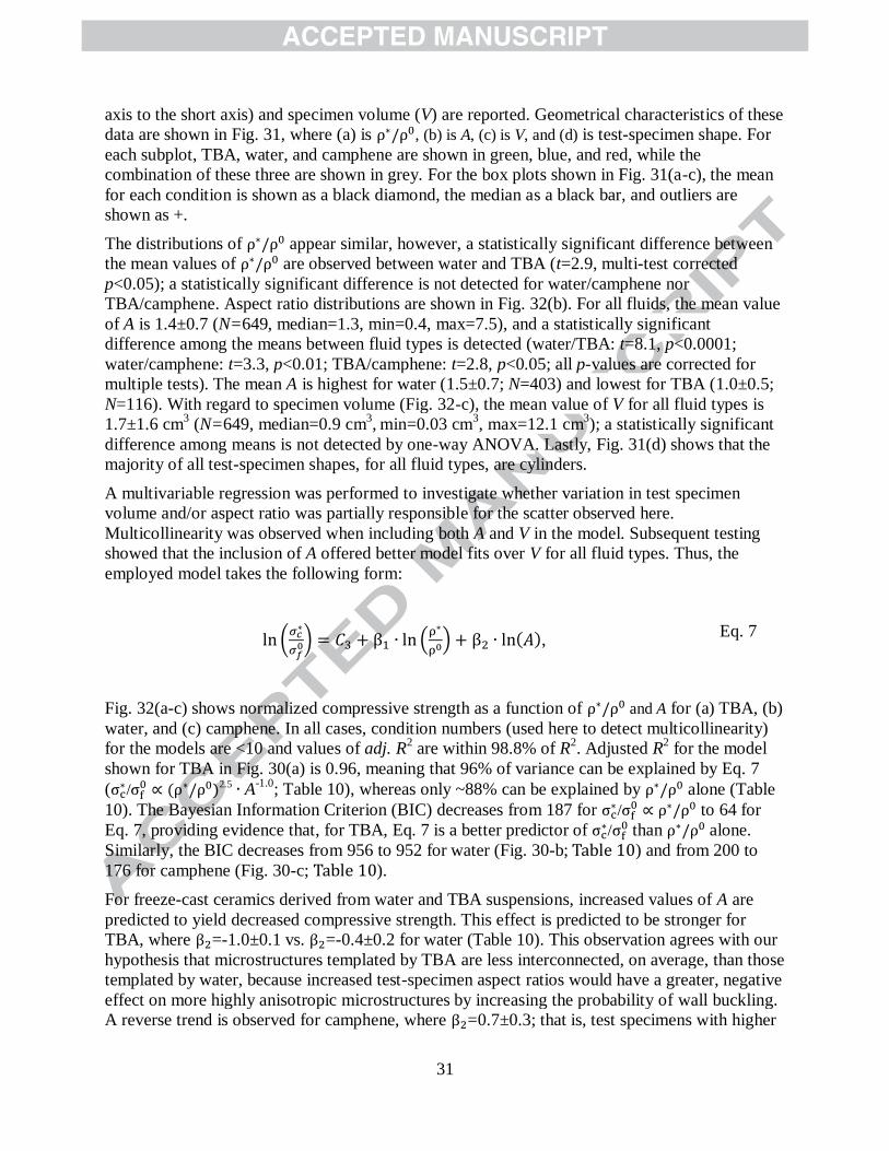
31
axis to the short axis) and specimen volume (V) are reported. Geometrical characteristics of these
data are shown in Fig. 31, where (a) is , (b) is A, (c) is V, and (d) is test-specimen shape. For
each subplot, TBA, water, and camphene are shown in green, blue, and red, while the
combination of these three are shown in grey. For the box plots shown in Fig. 31(a-c), the mean
for each condition is shown as a black diamond, the median as a black bar, and outliers are
shown as +.
The distributions of appear similar, however, a statistically significant difference between
the mean values of are observed between water and TBA (t=2.9, multi-test corrected
p<0.05); a statistically significant difference is not detected for water/camphene nor
TBA/camphene. Aspect ratio distributions are shown in Fig. 32(b). For all fluids, the mean value
of A is 1.4±0.7 (N=649, median=1.3, min=0.4, max=7.5), and a statistically significant
difference among the means between fluid types is detected (water/TBA: t=8.1, p<0.0001;
water/camphene: t=3.3, p<0.01; TBA/camphene: t=2.8, p<0.05; all p-values are corrected for
multiple tests). The mean A is highest for water (1.5±0.7; N=403) and lowest for TBA (1.0±0.5;
N=116). With regard to specimen volume (Fig. 32-c), the mean value of V for all fluid types is
1.7±1.6 cm3 (N=649, median=0.9 cm
3, min=0.03 cm
3, max=12.1 cm
3); a statistically significant
difference among means is not detected by one-way ANOVA. Lastly, Fig. 31(d) shows that the
majority of all test-specimen shapes, for all fluid types, are cylinders.
A multivariable regression was performed to investigate whether variation in test specimen
volume and/or aspect ratio was partially responsible for the scatter observed here.
Multicollinearity was observed when including both A and V in the model. Subsequent testing
showed that the inclusion of A offered better model fits over V for all fluid types. Thus, the
employed model takes the following form:
, Eq. 7
Fig. 32(a-c) shows normalized compressive strength as a function of and A for (a) TBA, (b)
water, and (c) camphene. In all cases, condition numbers (used here to detect multicollinearity)
for the models are <10 and values of adj. R2 are within 98.8% of R
2. Adjusted R
2 for the model
shown for TBA in Fig. 30(a) is 0.96, meaning that 96% of variance can be explained by Eq. 7
( /
2.5 A-1.0; Table 10), whereas only ~88% can be explained by alone (Table
10). The Bayesian Information Criterion (BIC) decreases from 187 for /
to 64 for
Eq. 7, providing evidence that, for TBA, Eq. 7 is a better predictor of /
than alone.
Similarly, the BIC decreases from 956 to 952 for water (Fig. 30-b; ) and from 200 to
176 for camphene (Fig. 30-c; ).
For freeze-cast ceramics derived from water and TBA suspensions, increased values of A are
predicted to yield decreased compressive strength. This effect is predicted to be stronger for
TBA, where =-1.0±0.1 vs. =-0.4±0.2 for water (Table 10). This observation agrees with our
hypothesis that microstructures templated by TBA are less interconnected, on average, than those
templated by water, because increased test-specimen aspect ratios would have a greater, negative
effect on more highly anisotropic microstructures by increasing the probability of wall buckling.
A reverse trend is observed for camphene, where =0.7±0.3; that is, test specimens with higher

32
aspect ratios are predicted to fail at increased compressive strengths relative to their lower aspect
ratio counterparts.
The relatively high negative value of for TBA and positive value for camphene may be
influenced by the distribution of test-specimen shapes shown in Fig. 31(d). Cylinders make up
the majority of all test-specimen shapes, however, the percentage of cylinders is highest for
camphene (~80% of test-specimens) and lowest for TBA (~50%). Conversely, most cube
specimens are represented by TBA whereas no data are available for cube specimens for
camphene. Research on the influence of test-specimen shape on compressive properties is largely
limited to that for concrete. Increased aspect ratios are reported to have a larger, negative effect
on the compressive strength of bar-shaped specimens vs. cylinders [512]. Increased aspect ratio
has also been reported to increase the compressive strength of cylinders and decrease the
compressive strength of bars [513]. The over-representation of cylinder specimens for camphene
relative to other fluids may be partially responsible for the reverse trend of A for camphene.
To test the influence of specimen shape on resulting compressive properties, a dummy variable
for test-specimen shape (S) was added to Eq. 7, where bar and cube specimens were grouped
(under the assumption that predictor variable A captures the difference between a bar and a cube)
and given a value of S=1, whereas for cylinders, S=0 (Eq. 8).
, Eq. 8
The resulting coefficient of S for TBA, = -0.6±0.2) predicts a reduction of ~60% in
compressive strength for bar-shaped vs. cylinder specimens (holding all other variables
constant). The reverse trend is found for water, where = 0.4±0.2); that is, bar-shaped
specimens are predicted to yield ~40% higher compressive strengths relative to cylinder-shaped
specimens (holding all other variables constant). Inclusion of S as a dummy predictor variable
for camphene was statistically insignificant. As shown in Fig. 31(d), the distribution of cylinder
and bar specimens is highly skewed, thus it is difficult to draw any conclusions here.
Nevertheless, this highlights an important issue regarding the need for adherence to generalized
testing procedures. The mean value of A for cylinder-shaped test specimens is rather low;
1.3±0.3 and 0.6±0.3 for aqueous and TBA systems, respectively. A combination of friction at the
interfaces and a low aspect ratio leads to a anisotropic stress distribution within the samples
during testing and may result in barreling of cylindrically-shaped test specimens [514], resulting
in decreased predictability of strength properties.
In Fig. 32(b) for water, data point color denotes pore structure, where blue is lamellar, red is
dendritic, and green is honeycomb. Scatter is observed for dendritic structures above and below
the regression line in Fig. 32(b). However, given that dendritic branching increases
interconnectedness of pore walls, a transition to a dendritic structure should result in increased
compressive strengths, especially at low values of . Data in Fig. 32(b) do not support this
prediction, which is likely attributable to the difficulty in drawing qualitative distinctions
between what constitutes lamellar vs. dendritic morphologies, as discussed earlier. A quantitative
approach, such as that employed by Ghosh et al. [515] through the use of a “bridge density”
factor, where the number of interconnections between lamellae are countered and related to area

33
of the region, holds much utility provided its quantification is utilized in more studies. On the
other hand, data corresponding to honeycomb pore structures (green) are mostly observed above
the regression line.
4.1.2.4. Comparison with previous modeling approaches
These results contradict those reported in previous reviews [159, 516, 517], where the authors
determined that the open-cell micromechanical model was inappropriate for describing the
compressive response of freeze-cast metals and ceramics. Instead, the Zhang and Ashby [491]
out-of-plane honeycomb model was utilized to describe freeze-cast ceramic and metal materials:
, Eq. 9
where E0 is the elastic modulus of the bulk material. The above relation describes failure by
elastic buckling and is an approximation based on a model for describing elastomeric
honeycomb materials in compression, where =0.9 GPa [491] Failure by elastic buckling has
been reported for some anisotropic freeze-cast ceramics, including zeolite/bentonite composites
[294] and titanium dioxide (TiO2)[296], and we find some support for it here. However, there are
at least two issues with extending Eq. 9 to ceramic materials. First, the elastic deformation region
for elastomeric materials is comparatively longer than that of ceramics; even still, the elastomeric
materials studied in [491] failed by buckling only when <0.12, above which, they failed by
fracture. Second, the value of E0 for ceramic materials is significantly higher than that for typical
elastomeric materials; given the prefactor of 6 in Eq. 1, predicted values of are unreasonably
high (e.g., for an Al2O3 material with =0.4 and E0=376 GPa [518]; by Eq. 8, 44 GPa,
which is ~50 times higher than the compressive strength of fully-dense Al2O3, 2.95 GPa [519]).
Alternative models of elastic buckling failure, which predict more reasonable values of
compressive strength for anisotropic ceramic materials, can be found in refs.[294, 296].
Upon analyzing freeze-cast metals and ceramics independently, we find that the open-cell model
is appropriate for describing anisotropic freeze-cast metals, especially when the value of the
intercept is obtained by fitting experimental data to the open-cell model. The open-cell model
accounts for ~53% variance in values of normalized compressive strength for freeze-cast
ceramics, which is lower than that explained for metals (~67%). However, we do not find a
significant difference between values of the coefficient of determination when fitting anisotropic
vs. isotropic freeze-cast ceramics to the open-cell model; albeit, 78% of these data represent
anisotropic materials whereas only 22% of these data are obtained from isotropic structures.
Upon categorizing by pore structure for ceramics, we find that the open-cell model is a
statistically better fit for anisotropic dendritic and isotropic equiaxed structures in comparison to
other pore structures; for lamellar, honeycomb, and cellular structures, we find that neither the
open-cell nor the honeycomb model offers a good fit to these data. The scatter observed for
ceramics may also be due to other factors that are inherent to ceramic processing; e.g.,
microporosity within cell walls, variance in test specimen volume/aspect ratio, etc.
5. Future directions
34
Freeze-casting produces materials with complex, three-dimensional pore structures which may
be tuned during the solidification process. The technique is highly researched, mainly because:
(i) the number of potential applications is vast and (ii) initial set-up costs are relatively low
[520]. Moving towards commercialization of freeze-cast materials requires (i) improvements in
reproducibility [292] and (ii) the ability to scale-up economically, the technique for industrial-
scale processing. We focus on the former issue here. The aim of the FreezeCasting.net database
is to facilitate broad dissemination of relevant data to freeze-casting researchers, promote better
informed experimental design, and encourage modeling efforts that relate processing conditions
to microstructure formation and material properties. Nevertheless, the scatter present in many of
these plots is daunting. In the following, we offer some recommendations for finding and
utilizing trends in these data.
5.1. Utilizing regression models
Regression models are provided for the following relationships: (i) initial solid fraction and final
porosity (Table 1), (ii) solidification velocity (Table 3) and cooling rate (Table 4) with respect to:
structure wavelength, pore width, and wall width, and (iii) relative density and compressive
strength (Tables 7-10). Both general and more specific models are provided; for the latter,
distinctions are made between (i) solidified, unsintered and sintered samples, (ii) anisotropic and
isotropic structures, (iii) fluid type, and (iv) material type.
The utility of these regression models is mainly limited to providing a means for outlier
identification, which upon investigation, may lead to a better understanding of the factors that
influence a specimen’s propensity to exhibit certain characteristics or properties. Given the large
number of data points available, the regression models also provide a small degree of predictive
power for future observations and offer a means for comparing new experimental data to an
established norm. To improve reproducibility, we need to identify and understand the major
factors leading to the scatter observed in these figures.
5.2. Understanding scatter
Data scatter may be reduced by removing outliers, or data points that are anomalous based on
their position relative to neighboring points. To present an accurate depiction of the present state
of the field, we did not exclude outlying data points. Varying degrees of ambiguity are always
present when determining criteria for defining outliers. In many of the relationships explored, we
do not sufficiently understand the reasons for outlying data points. Thus, outlier identification
(and subsequent removal) would be based on assigning cutoffs that are largely arbitrary in
nature. A better understanding of outliers will offer improved models.
5.2.1. Determining the origins of scatter
Fig. 14(a) and (c) show the relationship between total porosity ( ) and initial suspension
volume fraction ( ) for materials fabricated using (a) water and (c) tert-butyl alcohol
suspensions. A visual comparison of these plots is misleading in that scatter appears to be
somewhat consistent between the plots. However, we obtained a regression model for Eq. 1 that
accounted for 43% variance in as a function of for (a), whereas we are unable to fit a
statistically significant relationship in (c). Fig. 14(a) contains 2,044 data points, whereas (c)
contains only 408. The large number of data points in (a) makes it difficult to see that a relatively
large number of these data are concentrated about the regression line. Thus, rather than relying
35
on visual cues, we must use statistical descriptions of these relationships to determine the relative
significance of scatter.
An additional observation of Fig. 14(a) was that the inclusion of data corresponding to
unsintered samples (N = 458) improved the regression model. When sintered data were
considered alone, only 35% (vs. 43%) variance in as a function of was predicted by Eq. 1.
In considering the relationship between initial solid fraction and porosity, we determined that
volumetric changes associated with post-solidification processing are likely responsible for a
great deal of the scatter observed in Figs. 13-15; that is, materials that exhibit the lowest rates of
sintering shrinkage (e.g., polymers) show greater dependence of porosity on initial solid fraction.
A comparison of data scatter in Fig. 17 and Fig. 20 is less straightforward. Fig. 17 shows the
relationship between microstructural parameters (structure wavelength, pore width, and wall
width) and solidification velocity, whereas Fig. 20 shows the relationship between the same
microstructural parameters and cooling rate. Significantly more scatter is observed in Fig. 20
than Fig. 17, but in this case, it is likely that scatter results from numerous variables that remain
unaccounted for (discussed in Section 3.4.2).
5.2.2. Defining the input system
In many cases, scatter is likely attributable to varying material types and processing parameters.
Thus, better predictive power may be obtained by reducing the degrees of freedom by keeping
more variables constant. We demonstrated this process when considering the relationship
between the particle volume fraction and porosity. For ceramic materials fabricated via aqueous
processing routes, we obtained a regression model for Eq. 1 that accounted for 36% of variance
in as a function of . When holding the additional variable of material type constant, we
obtained a model that accounted for ~93% of this variance for sintered titanium dioxide (TiO2,
[38, 188, 296, 391-394]). The web-based application (http://www.freezecasting.net/plotting) may
be used to facilitate this process. Users may plot relationships between selected variables while
holding other variables constant; simple regression models are provided based on these inputs.
5.2.3. Assessing reproducibility
In examining the reproducibility of ZrO2 scaffolds, Naleway et al. found that, although
scaffolds produced using the same processing parameters showed similarity, statistically
significant differences in both microstructural and mechanical characteristics were found. The
authors posit that the solidification process itself is likely the largest source of variation. This is
an important conclusion that may get lost in a systematic analysis that includes many studies. In
such case, scatter is dominated by differing processing conditions between labs and an attempt to
compare materials that are fundamentally different (e.g., ZrO2 is more difficult to sinter than
TiO2; thus, ZrO2 scaffolds will likely exhibit greater microporosity). Nevertheless, a qualitative
assessment of scatter observed here shows evidence of the authors’ conclusion. The greatest
scatter is observed in plots depicting relationships between solidification conditions and
microstructural parameters (e.g., Figs. 17-20 and 22).
5.3. Reporting of experimental methods
In their meta-analysis of freeze-cast materials, Deville et al. [159] discuss the importance of
reporting all experimental methods, including those related to both processing and
characterization. Indeed, the utility of a systematic analysis of many papers, such as this, is
dependent on the quality of data available. In particular, we found that the: (i) number of

36
samples, (ii) dimensions of samples (especially those utilized for mechanical testing), (iii)
microporosity (porosity within cell walls, especially for ceramics as described in Section 4.1.2),
(iv) and impurity concentrations (for metals), are often unreported. The number of samples tested
to determine mechanical properties is more often reported than the number of samples used to
determine average values of microstructural parameters. When provided, the freezecasting.net
database includes the number of samples used to determine mean values of a reported parameter.
Future analyses may utilize this information to obtain better models by identifying parameters of
interest and weighing corresponding data points by the number of samples analyzed. Given that
this information is unavailable for more than 50% of studies, we were unable to utilize this
approach here.
6. Concluding remarks
The newly established FreezeCasting.net open-data repository contains, as of August 2017,
experimental data from over 800 papers published on the freeze-casting technique pertaining to
data which relate processing conditions to microstructure and material properties. The aim of the
database and the present paper is to facilitate broad dissemination of relevant data to freeze-
casting researchers to promote better informed experimental design, to encourage industrial use
of freeze-casting, and to accelerate modeling efforts that relate processing conditions to
microstructure formation and material properties.
Microstructural characteristics of freeze-cast materials are summarized, and key processing-
structure-property relationships are reviewed and tested against literature data contained within
the FreezeCasting.net database. The following conclusions are drawn:
All materials
1. The relationship between porosity and solid particle fraction in the suspension is
minimally dependent on the type of fluid employed, but highly correlated with the
material type (i.e., metal, ceramic, or polymer). Sintering shrinkage is also an
important factor, wherein, materials that exhibit the lowest rates of sintering
shrinkage (e.g., polymers) show greater dependence of porosity on initial solid
fraction.
2. The range of pore width attainable during freeze-casting is not highly dependent
on total porosity.
Anisotropic materials derived from aqueous suspensions
3. Structure wavelength - defined as the sum of the widths of one lamellar pore and
its adjacent wall - correlates with solidification velocity; this relationship is
statistically weaker when considering dependencies of only pore width or only
wall width on solidification velocity and strongest when considering sublimated,
but not sintered samples in comparison to sintered samples.
4. Cooling rate - usually defined as the rate at which the freezing substrate (on which
the sample mold is placed at the start of solidification) is cooled to a set, minimal
temperature – does not significantly correlate with microstructural parameters in
freeze-cast materials.
Metals

37
5. For anisotropic freeze-cast, sintered metals, the relationship between compressive
strength and relative density is best described by the Gibson-Ashby open-cell
model when the relative density of the material is less than 0.5. At higher relative
densities, the out-of-plane honeycomb model is a better fit.
Ceramics
6. For both anisotropic and isotropic freeze-cast ceramics, the Gibson and Ashby
open-cell model offers a better fit to experimental data than the honeycomb
model; these results contradict previous reviews on this topic.
7. For anisotropic freeze-cast ceramics derived from particle suspensions using
water, camphene, and tert-butyl alcohol as the fluid, improved regression models
predicting compressive strength are obtained when considering test specimen
aspect ratio along with relative density. However, a decrease in compressive
strength is predicted for increased test-specimen aspect ratios for materials
derived from water and tert-butyl alcohol suspensions, whereas the reverse is
found for camphene. Further testing is needed to clarify this issue.
Acknowledgements
This work was supported by grants from NASA’s Physical Sciences Research Program,
MaterialsLab Open Science Campaign (NNH15ZTT002N) and NASA Office of Education and
the Science Mission Directorate (NNH15ZDA010C). KS was supported by a scholarship through
the Jack Kent Cooke Foundation. The authors acknowledge Dr. Sylvain Deville (CNRS, France)
for numerous discussions on the FreezeCasting.net website, database, and preparation of this
manuscript; the following individuals are also acknowledged for their helpful feedback and
suggestions on the FreezeCasting.net website design: Mr. Jon Chambers (School of the Art
Institute of Chicago, USA), Mr. Maxime Garnier (ETH, Switzerland), Dr. Adam Stevenson
(Saint-Gobain, France). The authors acknowledge Mr. Aaron Shelhamer (Northern Illinois
University, USA) for his assistance with the website interactive plotting application.

38
References
[1] S. Madihally, H. Matthew, Porous chitosan scaffolds for tissue engineering, Biomater. 20(12)
(1999) 1133-1142.
[2] H. Schoof, L. Bruns, A. Fischer, I. Heschel, G. Rau, Dendritic ice morphology in
unidirectionally solidified collagen suspensions, J. Cryst. Growth 209(1) (2000) 122-129.
[3] U. Wegst, M. Schecter, A. Donius, P. Hunger, Biomaterials by freeze casting, Philos. Trans.
R. Soc. 368(1917) (2010) 2099-2121.
[4] N. Francis, P. Hunger, A. Donius, U. Wegst, M. Wheatley, Strategies for neurotrophin-3 and
chondroitinase ABC release from freeze-cast chitosan–alginate nerve-guidance scaffolds, Journal
of tissue engineering and regenerative medicine (2014).
[5] S. Deville, Freeze-casting of porous biomaterials: Structure, properties and opportunities,
Mater. 3(3) (2010) 1913-1927.
[6] T. Fukasawa, Z. Deng, M. Ando, T. Ohji, Y. Goto, Pore structure of porous ceramics
synthesized from water-based slurry by freeze-dry process, J. Mater. Sci. 36(10) (2001) 2523-
2527.
[7] C. Gaudillere, J. Garcia-Fayos, M. Balaguer, J. Serra, Enhanced Oxygen Separation through
Robust Freeze-Cast Bilayered Dual-Phase Membranes, Chemsuschem 7(9) (2014) 2554-2561.
[8] C. Gaudillere, J. Garcia‐ Fayos, J. Serra, Oxygen Permeation Improvement under CO2‐ Rich
Environments through Catalytic Activation of Hierarchically Structured Perovskite Membranes,
ChemPlusChem 79(12) (2014) 1720-1725.
[9] J. Moon, H. Hwang, M. Awano, K. Maeda, Preparation of NiO-YSZ tubular support with
radially aligned pore channels, Mater. Lett. 57(8) (2003) 1428-1434.
[10] T. Cable, S. Sofie, A symmetrical, planar SOFC design for NASA's high specific power
density requirements, J. Power Sources 174(1) (2007) 221-227.
[11] N. Mansor, J. Jia, T. Miller, T. Suter, A. Jorge, C. Gibbs, P. Shearing, P. McMillan, C.
Mattevi, M. Shaffer, Graphitic Carbon Nitride-Graphene Hybrid Nanostructure as a Catalyst
Support for Polymer Electrolyte Membrane Fuel Cells, ECS Transactions 75(14) (2016) 885-
897.
[12] N. Hedayat, Y. Du, H. Ilkhani, Review on fabrication techniques for porous electrodes of
solid oxide fuel cells by sacrificial template methods, Renewable and Sustainable Energy
Reviews (2017).
[13] T.L. Cable, J.A. Setlock, S.C. Farmer, Regenerative operation of the NASA symmetrical
support solid oxide fuel cell in: N.P. Bansal (Ed.), Advances in Solid Oxide Fuel Cells Iii2008,
pp. 103-113.
[14] C. Stoots, J. O’Brien, T. Cable, Test results from the Idaho National Laboratory of the
NASA bi-supported cell design, ASME 2009 International Mechanical Engineering Congress
and Exposition, American Society of Mechanical Engineers, 2009, pp. 611-616.
[15] T. Wu, W. Zhang, B. Yu, J. Chen, A novel electrolyte-electrode interface structure with
directional micro-channel fabricated by freeze casting: A minireview, International Journal of
Hydrogen Energy (2017).
[16] Y. Du, J. Persky, K. Zhao, H. Ilkhani, T. Woodson, B. Emley, N. Hedayat, Fabrication and
Electrochemical Characterization of Freeze-Cast Tubular Solid Oxide Fuel Cells, ECS
Transactions 78(1) (2017) 1885-1895.
[17] Y. Chino, D.C. Dunand, Directionally freeze-cast titanium foam with aligned, elongated
pores, Acta Mater. 56(1) (2008) 105-113.

39
[18] A. Szepes, J. Ulrich, Z. Farkas, J. Kovacs, P. Szabo-Revesz, Freeze-casting technique in the
development of solid drug delivery systems, Chem. Eng. Prog. 46(3) (2007) 230-238.
[19] P. Frohberg, T. Nguyen, J. Ulrich, New sspects in the formulation of drugs based on three
case studies, Molecules 21(5) (2016) 577.
[20] J.A. Searles, J.F. Carpenter, T.W. Randolph, Annealing to optimize the primary drying rate,
reduce freezing-induced drying rate heterogeneity, and determine T-g ' in pharmaceutical
lyophilization, Journal of Pharmaceutical Sciences 90(7) (2001) 872-887.
[21] A. Witte, J. Ulrich, An Alternative Technology to Form Tablets, Chem. Eng. Technol. 33(5)
(2010) 757-761.
[22] P. Nguyen, J. Ulrich, Preconditions for designing a freeze casting process of
drugs‐ Rheological properties of suspensions, Chemical Engineering & Technology (2016).
[23] M. Nugent, C. Higginbotham, Preparation of a novel freeze thawed poly (vinyl alcohol)
composite hydrogel for drug delivery applications, European Journal of Pharmaceutics and
Biopharmaceutics 67(2) (2007) 377-386.
[24] P. Gannon, S. Sofie, M. Deibert, R. Smith, V. Gorokhovsky, Thin film YSZ coatings on
functionally graded freeze cast NiO/YSZ SOFC anode supports, Journal of Applied
Electrochemistry 39(4) (2009) 497-502.
[25] P. Nguyen, J. Ulrich, Fast dispersible cocoa tablets: A case study of freeze-casting applied
to foods, Chem. Eng. Technol. 37(8) (2014) 1376-1382.
[26] C. Ji, M. Xu, S. Bao, C. Cai, Z. Lu, H. Chai, F. Yang, H. Wei, Self-assembly of three-
dimensional interconnected graphene-based aerogels and its application in supercapacitors,
Journal of Colloid and Interface Science 407 (2013) 416-424.
[27] K. Lee, Y. Lee, S. Lee, J. Ha, S. Lee, J. Son, Ice-templated Self-assembly of VOPO4–
Graphene Nanocomposites for Vertically Porous 3D Supercapacitor Electrodes, Scientific
reports 5 (2015).
[28] Y. Shao, M. El‐ Kady, C. Lin, G. Zhu, K. Marsh, J. Hwang, Q. Zhang, Y. Li, H. Wang, R.
Kaner, 3D Freeze‐ Casting of Cellular Graphene Films for Ultrahigh‐ Power‐ Density
Supercapacitors, Advanced Materials (2016).
[29] Y. Wei, B. Sun, D. Su, J. Zhu, G. Wang, 3D Free‐ Standing NiCo2O4@ graphene Foam for
High‐ Performance Supercapacitors, Energy Technol. (2016).
[30] C. Zhu, T. Liu, F. Qian, T. Han, E. Duoss, J. Kuntz, C. Spadaccini, M. Worsley, Y. Li,
Supercapacitors based on 3D hierarchical graphene aerogels with periodic macropores, Nano
letters (2016).
[31] M. Kota, X. Yu, S. Yeon, H. Cheong, H. Park, Ice-templated three dimensional nitrogen
doped graphene for enhanced supercapacitor performance, J. Power Sources 303 (2016) 372-
378.
[32] Y. Shin, Y. Sa, S. Park, J. Lee, K. Shin, S. Joo, H. Ko, An ice-templated, pH-tunable self-
assembly route to hierarchically porous graphene nanoscroll networks, Nanoscale 6(16) (2014)
9734-9741.
[33] E. Khaleghi, E. Olevsky, M. Meyers, Uniaxial Freezing, Freeze-Drying, and Anodization
for Aligned Pore Structure in Dye-Sensitized Solar Cells, Journal of the American Ceramic
Society 92(7) (2009) 1487-1491.
[34] C. Suwanchawalit, A. Patil, R. Kumar, S. Wongnawa, S. Mann, Fabrication of ice-
templated macroporous TiO2-chitosan scaffolds for photocatalytic applications, J. Mater. Chem.
19(44) (2009) 8478-8483.
40
[35] G. Drisko, M. Kimling, N. Scales, A. Ide, E. Sizgek, R. Caruso, V. Luca, One-Pot
Preparation and Uranyl Adsorption Properties of Hierarchically Porous Zirconium Titanium
Oxide Beads using Phase Separation Processes to Vary Macropore Morphology, Langmuir
26(22) (2010) 17581-17588.
[36] S. Mukai, H. Nishihara, S. Shichi, H. Tamon, Preparation of porous TiO2 cryogel fibers
through unidirectional freezing of hydrogel followed by freeze-drying, Chemistry of materials
16(24) (2004) 4987-4991.
[37] Nieto-S, G. Palmisano, M. Ferrer, M. Concepcion, S. Yurdakal, V. Augugliaro, M. Pagliaro,
F. del Monte, Self-assembled titania-silica-sepiolite based nanocomposites for water
decontamination, Journal of Materials Chemistry 19(14) (2009) 2070-2075.
[38] Z. Xing, W. Zhou, F. Du, L. Zhang, Z. Li, H. Zhang, W. Li, Facile Synthesis of Hierarchical
Porous TiO2 Ceramics with Enhanced Photocatalytic Performance for Micropolluted Pesticide
Degradation, ACS Appl. Mater. Inter. 6(19) (2014) 16653-16660.
[39] Z. Xing, J. Li, Q. Wang, W. Zhou, G. Tian, K. Pan, C. Tian, J. Zou, H. Fu, A Floating
Porous Crystalline TiO2 Ceramic with Enhanced Photocatalytic Performance for Wastewater
Decontamination, Eur. J. Inorg. Chem. (13) (2013) 2411-2417.
[40] C. Chen, Y. Zhang, J. Zeng, F. Zhang, K. Zhou, C. Bowen, D. Zhang, Aligned macroporous
TiO 2/chitosan/reduced graphene oxide (rGO) composites for photocatalytic applications,
Applied Surface Science (2017).
[41] J. Kang, H. Choi, J. Kim, H. Park, J. Kim, J. Choi, S. Yu, K. Lee, Y. Kang, S. Park,
Multidimensional Anodized Titanium Foam Photoelectrode for Efficient Utilization of Photons
in Mesoscopic Solar Cells, Small (2017).
[42] J.S. Kang, Y. Noh, J. Kim, H. Choi, T.H. Jeon, D. Ahn, J.Y. Kim, S.H. Yu, H. Park, J.H.
Yum, W. Choi, D.C. Dunand, H. Choe, Y.E. Sung, Iron Oxide Photoelectrode with
Multidimensional Architecture for Highly Efficient Photoelectrochemical Water Splitting,
Angew. Chem.-Int. Edit. 56(23) (2017) 6583-6588.
[43] H. Liu, X. Liu, S. Mu, S. Wang, S. Wang, L. Li, E.P. Giannelis, A novel fabrication
approach for three-dimensional hierarchical porous metal oxide/carbon nanocomposites for
enhanced solar photocatalytic performance, Catalysis Science & Technology 7(9) (2017) 1965-
1970.
[44] M. Barrow, A. Eltmimi, A. Ahmed, P. Myers, H. Zhang, Frozen polymerization for aligned
porous structures with enhanced mechanical stability, conductivity, and as stationary phase for
HPLC, J. Mater. Chem. 22(23) (2012) 11615-11620.
[45] J. Kuang, Z. Dai, L. Liu, Z. Yang, M. Jin, Z. Zhang, Synergistic effects from graphene and
carbon nanotubes endow ordered hierarchical structure foams with a combination of
compressibility, super-elasticity and stability and potential application as pressure sensors,
Nanoscale 7(20) (2015) 9252-9260.
[46] J. Kuang, L. Liu, Y. Gao, D. Zhou, Z. Chen, B. Han, Z. Zhang, A hierarchically structured
graphene foam and its potential as a large-scale strain-gauge sensor, Nanoscale 5 (2013) 12171–
12177.
[47] C. Hou, H. Wang, Q. Zhang, Y. Li, M. Zhu, Highly Conductive, Flexible, and Compressible
All-Graphene Passive Electronic Skin for Sensing Human Touch, Advanced Materials 26 (2014)
5018–5024.
[48] Y. Li, M. Zhao, J. Chen, S. Fan, J. Liang, L. Ding, S. Chen, Flexible chitosan/carbon
nanotubes aerogel, a robust matrix for in-situ growth and non-enzymatic biosensing applications,
Sensors and Actuators B: Chemical 232 (2016) 750-757.
41
[49] K. Nam, H. Kim, H. Choi, H. Park, J. Kang, Y. Sung, H. Lee, H. Choe, Morphology and
gas-sensing properties of tin oxide foams with dual pore structure, J. Electron. Mater. (2017) 1-
9.
[50] H. Ma, Y. Li, S. Yang, F. Cao, J. Gong, Y. Deng, Effects of Solvent and Doping Acid on
the Morphology of Polyaniline Prepared with the Ice-Templating Method, Journal of Physical
Chemistry C 114(20) (2010) 9264-9269.
[51] H. Ma, Y. Gao, Y. Li, J. Gong, X. Li, B. Fan, Y. Deng, Ice-Templating Synthesis of
Polyaniline Microflakes Stacked by One-Dimensional Nanofibers, Journal of Physical Chemistry
C 113(21) (2009) 9047-9052.
[52] Y. de Hazan, Porous Ceramics, Ceramic/Polymer, and Metal-Doped Ceramic/Polymer
Nanocomposites via Freeze Casting of Photo-Curable Colloidal Fluids, J. Am. Ceram. Soc 95(1)
(2012) 177-187.
[53] P. Zuo, W. Zhang, J. Hua, Y. Ma, C. Du, X. Cheng, Y. Gao, G. Yin, A Novel One-
dimensional Reduced Graphene Oxide/Sulfur Nanoscroll Material and its Application in Lithium
Sulfur Batteries, Electrochimica Acta (2016).
[54] C. Stolze, T. Janoschka, S. Flauder, F. ller, M. Hager, U. Schubert, Investigation of ice-
templated porous electrodes for application in organic batteries, ACS Appl. Mater. Inter. (2016).
[55] J. Um, M. Choi, H. Park, Y. Cho, D. Dunand, H. Choe, Y. Sung, 3D macroporous electrode
and high-performance in lithium-ion batteries using SnO2 coated on Cu foam, Scientific reports
6 (2016).
[56] H. Choi, H. Park, J. Um, W. Yoon, H. Choe, Processing and characterization of titanium
dioxide grown on titanium foam for potential use as Li-ion electrode, Applied Surface Science
411 (2017) 363-367.
[57] J. Orlenius, O. Lyckfeldt, K. Kasvayee, P. Johander, Water based processing of LiFePO 4/C
cathode material for Li-ion batteries utilizing freeze granulation, Journal of Power Sources 213
(2012) 119-127.
[58] J. Cheng, G. Gu, Q. Guan, J. Razal, Z. Wang, X. Li, B. Wang, Synthesis of a porous sheet-
like V 2 O 5–CNT nanocomposite using an ice-templating ‘bricks-and-mortar’assembly
approach as a high-capacity, long cyclelife cathode material for lithium-ion batteries, Journal of
Materials Chemistry A 4(7) (2016) 2729-2737.
[59] Y. Li, C. Wu, Y. Bai, L. Liu, H. Wang, F. Wu, N. Zhang, Y. Zou, Hierarchical Mesoporous
Lithium-Rich Li [Li0. 2Ni0. 2Mn0. 6] O2 Cathode Material Synthesized via Ice Templating for
Lithium-Ion Battery, ACS Applied Materials & Interfaces 8(29) (2016) 18832-18840.
[60] L. Pei, Q. Jin, Z. Zhu, Q. Zhao, J. Liang, J. Chen, Ice-templated preparation and sodium
storage of ultrasmall SnO2 nanoparticles embedded in three-dimensional graphene, Nano
Research 8(1) (2015) 184-192.
[61] Y. Ma, R. Younesi, R. Pan, C. Liu, J. Zhu, B. Wei, K. Edström, Constraining Si Particles
within Graphene Foam Monolith: Interfacial Modification for High-Performance Li+Storage and
Flexible Integrated Configuration, Advanced Functional Materials 26(37) (2016) 6797-6806.
[62] H.W. Zhai, P.Y. Xu, M.Q. Ning, Q. Cheng, J. Mandal, Y. Yang, A Flexible Solid
Composite Electrolyte with Vertically Aligned and Connected Ion-Conducting Nanoparticles for
Lithium Batteries, Nano Letters 17(5) (2017) 3182-3187.
[63] F. Tirado, J. Huang, D. Dunand, Ice-templated silicon foams with aligned lamellar channels,
MRS Communications (2017) 1-5.

42
[64] S. Bargmann, I. Scheider, T. Xiao, E. Yilmaz, G. Schneider, N. Huber, Towards bio-
inspired engineering materials: Modeling and simulation of the mechanical behavior of
hierarchical bovine dental structure, Comput. Mater. Sci. 79 (2013) 390–401.
[65] U. Hess, G. Mikolajczyk, L. Treccani, P. Streckbein, C. Heiss, S. Odenbach, K. Rezwan,
Multi-loaded ceramic beads/matrix scaffolds obtained by combining ionotropic and freeze
gelation for sustained and tuneable vancomycin release, Materials Science and Engineering: C
67 (2016) 542-553.
[66] S.J. Hong, H.S. Yu, H.W. Kim, Preparation of porous bioactive ceramic microspheres and
in vitro osteoblastic culturing for tissue engineering application, Acta Biomaterialia 5(5) (2009)
1725-1731.
[67] M. Mao, J. He, Y. Liu, X. Li, D. Li, Ice-template-induced silk fibroin-chitosan scaffolds
with predefined microfluidic channels and fully porous structures, Acta Biomaterialia 8(6)
(2012) 2175-2184.
[68] P. Munier, K. Gordeyeva, L. Bergström, A. Fall, Directional freezing of nanocellulose
dispersions aligns the rod-like particles and produces low-density and robust particle networks,
Biomacromolecules (2016).
[69] H.S. Noguchi, Masataka; Watanabe, Arata; Tsukanishi, Toshinori; Wadano, Yasuyoshi;
Yamazaki, Masashi, A novel unidirectional porous hydroxyapatite in canines, Bioinspired
Biomimetic and Nanobiomaterials 3(4) (2014) 228-234.
[70] A. Ouyang, Q. Gong, J. Liang, Carbon Nanotube-Chitosan Composite Beads with Radially
Aligned Channels and Nanotube-Exposed Walls for Bilirubin Adsorption, Advanced
Engineering Materials 17(4) (2015) 460-466.
[71] A. Ouyang, C. Wang, S. Wu, E. Shi, W. Zhao, A. Cao, D. Wu, Highly Porous Core-Shell
Structured Graphene-Chitosan Beads, Acs Applied Materials & Interfaces 7(26) (2015) 14439-
14445.
[72] A. Pannier, M. Mkandawire, U. Soltmann, W. Pompe, H. Böttcher, Biological activity and
mechanical stability of sol–gel-based biofilters using the freeze-gelation technique for
immobilization of Rhodococcus ruber, Applied microbiology and biotechnology 93 (2012)
1755–1767.
[73] X. Peng, C. He, J. Liu, H. Wang, Biomimetic jellyfish-like PVA/graphene oxide
nanocomposite hydrogels with anisotropic and pH-responsive mechanical properties, Journal of
Materials Science 51(12) (2016) 5901-5911.
[74] M. Serrano, S. Nardecchia, C. García-Rama, M. Ferrer, J. Collazos-Castro, F. del Monte, M.
Gutiérrez, Chondroitin sulphate-based 3D scaffolds containing MWCNTs for nervous tissue
repair, Biomaterials 35(5) (2014) 1543-1551.
[75] U. Shin, J. Park, S. Hong, J. Won, H. Yu, H. Kim, Porous biomedical composite
microspheres developed for cell delivering scaffold in bone regeneration, Materials Letters
64(20) (2010) 2261-2264.
[76] H. Noguchi, M. Sakane, A. Watanabe, T. Tsukanishi, Y. Wadano, M. Yamazaki, A novel
unidirectional porous hydroxyapatite in canines, Bioinspired, Biomimetic and Nanobiomaterials
3(4) (2014) 228-234.
[77] R. Touri, F. Moztarzadeh, Z. Sadeghian, D. Bizari, M. Tahriri, M. Mozafari, The use of
carbon nanotubes to reinforce 45S5 bioglass-based scaffolds for tissue engineering applications,
BioMed research international 2013 (2013).
43
[78] A. Wan, S. Inal, T. Williams, K. Wang, P. Leleux, L. Estevez, E. Giannelis, C. Fischbach,
G. Malliaras, D. Gourdon, 3D conducting polymer platforms for electrical control of protein
conformation and cellular functions, Journal of Materials Chemistry B 3(25) (2015) 5040-5048.
[79] J. Yang, X. Hu, R. Sultana, R. Day, P. Ichim, Structure design and manufacturing of layered
bioceramic scaffolds for load-bearing bone reconstruction, Biomedical Materials 10(4) (2015).
[80] X. Yao, H. Yao, Y. Li, Hierarchically aligned porous scaffold by ice-segregation-induced
self-assembly and thermally triggered electrostatic self-assembly of oppositely charged
thermosensitive microgels, Journal of Materials Chemistry 19(36) (2009) 6516-6520.
[81] J.J. Campbell, A. Husmann, R.D. Hume, C.J. Watson, R.E. Cameron, Development of
three-dimensional collagen scaffolds with controlled architecture for cell migration studies using
breast cancer cell lines, Biomaterials 114 (2017) 34-43.
[82] H. Ismail, S. Yau, R. Shamsudin, M. Hamid, R. Awang, Morphology and Phase
Identification of Bioactive Freeze-dried ß-CaSiO 3, Key Engineering Materials 694 (2016).
[83] S. Montesanto, G. Calòb, M. Cruciatac, L. Settannic, V. Brucatoa, V. LaCarrubbaa,
Optimization of environmental conditions for kefiran production by Kefir grain as scaffold for
tissue engineering, CHEMICAL ENGINEERING 49 (2016).
[84] Y. Li, L. Sun, H. Fu, X. Duan, Facile fabrication of a 3D electrospun fibrous mat by ice-
templating for a tumor spheroid culture, Polym. Chem. 7(44) (2016) 6805-6811.
[85] Y. Zhu, K. Song, S. Jiang, J. Chen, L. Tang, S. Li, J. Fan, Y. Wang, J. Zhao, T. Liu,
Numerical Simulation of Mass Transfer and Three-Dimensional Fabrication of Tissue-
Engineered Cartilages Based on Chitosan/Gelatin Hybrid Hydrogel Scaffold in a Rotating
Bioreactor, Applied Biochemistry and Biotechnology (2016) 1-17.
[86] M. Rodrigues, G. Balzan, M. Rosa, D. Gomes, E. deAzevedo, S. Singh, H. Matos, V.
Geraldes, The importance of heat flow direction for reproducible and homogeneous freezing of
bulk protein solutions, Biotechnology progress 29(5) (2013) 1212-1221.
[87] I. Aranaz, M.C. Gutierrez, M.L. Ferrer, F. del Monte, Preparation of Chitosan
Nanocompositeswith a Macroporous Structure by Unidirectional Freezing and Subsequent
Freeze-Drying, Marine Drugs 12(11) (2014) 5619-5642.
[88] S. Reed, G. Lau, B. Delattre, D. Lopez, A. Tomsia, B. Wu, Macro-and micro-designed
chitosan-alginate scaffold architecture by three-dimensional printing and directional freezing,
Biofabrication 8(1) (2016) 015003.
[89] Y. Gong, G. Han, Y. Zhang, J. Zhang, W. Jiang, Y. Pan, Research on the degradation
performance of the lotus nanofibers-alginate porous materials, Polymer Degradation and
Stability 118 (2015) 104-110.
[90] F. Jiang, S. Han, Y. Hsieh, Controlled defibrillation of rice straw cellulose and self-
assembly of cellulose nanofibrils into highly crystalline fibrous materials, Rsc Advances 3(30)
(2013) 12366-12375.
[91] J. Snyder, P. Hunger, C. Wang, Q. Hamid, U. Wegst, W. Sun, Combined multi-nozzle
deposition and freeze casting process to superimpose two porous networks for hierarchical three-
dimensional microenvironment, Biofabrication 6(1) (2014).
[92] E. Abraham, D. Weber, S. Sharon, S. Lapidot, O. Shoseyov, Multifunctional Cellulosic
Scaffolds from Modified Cellulose Nanocrystals, ACS Applied Materials & Interfaces (2017).
[93] A. Forget, M. Waibel, D. Rojas-Canales, S. Chen, N. Kawazoe, F. Harding, T. Loudovaris,
P. Coates, A. Blencowe, G. Chen, IGF-2 coated porous collagen microwells for the culture of
pancreatic islets, Journal of Materials Chemistry B 5(2) (2017) 220-225.

44
[94] K. Pawelec, D. Confalonieri, F. Ehlicke, H. van Boxtel, H. Walles, S. Kluijtmans,
Osteogenesis and mineralization of mesenchymal stem cells in collagen type I‐ based
recombinant peptide scaffolds, Journal of Biomedical Materials Research Part A (2017).
[95] F. Byette, F. Bouchard, C. Pellerin, J. Paquin, I. Marcotte, M.A. Mateescu, Cell-culture
compatible silk fibroin scaffolds concomitantly patterned by freezing conditions and salt
concentration, Polymer Bulletin 67(1) (2011) 159-175.
[96] M. Gutierrez, M. Jobbagy, N. Rapun, M.L. Ferrer, F. del Monte, A biocompatible bottom-
up route for the preparation of hierarchical biohybrid materials, Advanced Materials 18(9)
(2006) 1137.
[97] U.G. Wegst, H. Bai, E. Saiz, A.P. Tomsia, R.O. Ritchie, Bioinspired structural materials,
Nat Mater 14(1) (2015) 23-36.
[98] A. Studart, Bioinspired ceramics: Turning brittleness into toughness, Nature materials 13
(2014) 433–435.
[99] S. Scanlon, A. Aggeli, N. Boden, T. McLeish, P. Hine, R. Koopmans, C. Crowder,
Organisation of self-assembling peptide nanostructures into macroscopically ordered lamella-like
layers by ice crystallisation, Soft Matter 5(6) (2009) 1237-1246.
[100] D. Yang, Z. Zhao, F. Bai, S. Wang, A. Tomsia, H. Bai, Promoting Cell Migrat ion in Tissue
Engineering Scaffolds with Graded Channels, Advanced Healthcare Materials (2017).
[101] S. Chamary, D. Hautcoeur, J. Hornez, A. Leriche, F. Cambier, Bio-inspired hydroxyapatite
dual core-shell structure for bone substitutes, Journal of the European Ceramic Society (2017).
[102] S.W. Chen, N. Kawazoe, G.P. Chen, Biomimetic Assembly of Vascular Endothelial Cells
and Muscle Cells in Microgrooved Collagen Porous Scaffolds, Tissue Eng. Part C-Methods
23(6) (2017) 367-376.
[103] G. Offeddu, I. Mela, P. Jeggle, R. Henderson, S. Smoukov, M. Oyen, Cartilage-like
electrostatic stiffening of responsive cryogel scaffolds, Scientific Reports 7 (2017) 42948.
[104] S.I. Roohani-Esfahani, K. Lin, H. Zreiqat, Fabrication of bioinspired structured glass-
ceramics with enhanced fracture toughness, Journal of Materials Science 52(15) (2017) 9202-
9210.
[105] X.X. Sun, K.P. Wang, B.X. Zhang, F.D. Zou, G.W. Sun, W.L. Han, X.H. Wang,
Hierarchically Porous Cellulose Monolith Prepared by Combination of Ice-template Method and
Non-solvent-induced Phase Separation Method, Chem. Lett. 46(6) (2017) 792-794.
[106] Y. Tian, K. Liang, X. Wang, Y. Ji, Fabrication of Nanocomposite Bioelastomer Porous
Scaffold Based on Chitin Nanocrystal Supported Emulsion-Freeze-Casting, ACS Sustainable
Chemistry & Engineering 5(4) (2017) 3305-3313.
[107] R. Guo, P. Shen, C. Sun, Y. Wang, A. Shaga, Q. Jiang, Processing and mechanical
properties of lamellar-structured Al–7Si–5Cu/TiC composites, Materials & Design 106 (2016)
446-453.
[108] D. Hautcoeur, Y. Lorgouilloux, A. Leriche, M. Gonon, B. Nait-Ali, D. Smith, V. Lardot, F.
Cambier, Thermal conductivity of ceramic/metal composites from preforms produced by freeze
casting, Ceram. Int. (2016).
[109] Y. Koh, J. Sun, H. Kim, Freeze casting of porous Ni–YSZ cermets, Materials Letters 61(6)
(2007) 1283-1287.
[110] M. Launey, E. Munch, D. Alsem, E. Saiz, A. Tomsia, R. Ritchie, A novel biomimetic
approach to the design of high-performance ceramic–metal composites, J. R. Soc., Interface 7
(2010) 741–753.
45
[111] J. Lee, T. Yang, S. Yoon, B. Kim, H. Park, Recycling of coal fly ash for fabrication of
porous mullite composite, Adv. Mater. Res., Trans Tech Publ, 2011, pp. 1649-1652.
[112] Q. Liu, F. Ye, Y. Gao, S. Liu, H. Yang, Z. Zhou, Fabrication of a new SiC/2024Al co-
continuous composite with lamellar microstructure and high mechanical properties, J. Alloys
Compd. 585 (2014) 146-153.
[113] A. Shaga, P. Shen, R. Guo, Q. Jiang, Effects of oxide addition on the microstructure and
mechanical properties of lamellar SiC scaffolds and Al–Si–Mg/SiC composites prepared by
freeze casting and pressureless infiltration, Ceram. Int. 42(8) (2016) 9653-9659.
[114] R. Guo, H. Lv, P. Shen, Z. Hu, Q. Jiang, Lamellar-interpenetrated
Al−Si− g/Al2O3−ZrO2 composites prepared by freeze casting and pressureless infiltration,
Ceram. Int. 43(3) (2017) 3292-3297.
[115] J. Tang, Y. Chen, J. Sun, H. Wang, H. Liu, Q. Fan, Properties and application of oriented
porous SiC as transpiration cooling materials, in: W. Pan, J.H. Gong (Eds.), High Perform.
Ceram2007, pp. 1109-1112.
[116] H. Zhang, P. Shen, A. Shaga, R. Guo, Q. Jiang, Preparation of nacre-like composites by
reactive infiltration of a magnesium alloy into porous silicon carbide derived from ice template,
Materials Letters 183 (2016) 299-302.
[117] C. Gaudillere, L. Navarrete, J. Serra, CO2 hydrogenation on Ru/Ce based catalysts
dispersed on highly ordered micro-channelled 3YSZ monoliths fabricated by freeze-casting,
International Journal of Hydrogen Energy (2016).
[118] Y. Wang, P. Shen, R. Guo, Z. Hu, Q. Jiang, Developing high toughness and strength
Al/TiC composites using ice-templating and pressure infiltration, Ceram. Int. 43(4) (2017) 3831-
3838.
[119] P.K. Sahoo, R. Aepuru, H.S. Panda, D. Bahadur, Ice-templated synthesis of
multifunctional three dimensional graphene/noble metal nanocomposites and their mechanical,
electrical, catalytic, and electromagnetic shielding properties, Sci Rep 5 (2015) 17726.
[120] R.F. Guo, P. Shen, S.X. Li, A. Shaga, Q.C. Jiang, High compressive strength in nacre-
inspired Al-7Si-5Cu/Al2O3-ZrO2 composites at room and elevated temperatures by regulating
interfacial reaction, Ceramics International 43(9) (2017) 7369-7373.
[121] S. Flauder, R. Sajzew, F. ller, echanical properties of porous β-tricalcium phosphate
composites prepared by ice-templating and poly (ε-caprolactone) impregnation, ACS Appl.
Mater. Interf. 7 (2014) 845–851.
[122] T. Xu, C. Wang, C. Wang, Synthesis and magnetoelectric effect of composites with CoFe
2O4-epoxy embedded in 3-1 type porous PZT ceramics, Ceram. Int. (2015).
[123] E. Gorzkowski, M. Pan, Barium titanate-polymer composites produced via directional
freezing, Applications of Ferroelectrics, 2008. ISAF 2008. 17th IEEE International Symposium
on the, IEEE, 2008, pp. 1-2.
[124] E. Gorzkowski, M. Pan, Dielectric Composites for Naval Applications, Jom 66(2) (2014)
261-269.
[125] A. Dutta, S. Tekalur, Synthetic staggered architecture composites, Materials & Design 46
(2013) 802-808.
[126] X. Zeng, L. Ye, S. Yu, R. Sun, J. Xu, C. Wong, Facile Preparation of Superelastic and
Ultralow Dielectric Boron Nitride Nanosheets Aerogels via Freeze-Casting Process, Chemistry
of Materials (2015).

46
[127] H. Zhao, Y. Yue, L. Guo, J. Wu, Y. Zhang, X. Li, S. Mao, X. Han, Cloning Nacre's 3D
Interlocking Skeleton in Engineering Composites to Achieve Exceptional Mechanical Properties,
Advanced Materials (2016).
[128] D. Kim, C. Baek, H. Ma, D. Kim, Enhanced dielectric permittivity of BaTiO 3/epoxy resin
composites by particle alignment, Ceramics International 42(6) (2016) 7141-7147.
[129] G. Lian, C. Tuan, L. Li, S. Jiao, Q. Wang, K. Moon, D. Cui, C. Wong, Vertically Aligned
and Interconnected Graphene Networks for High Thermal Conductivity of Epoxy Composites
with Ultralow Loading, Chemistry of Materials 28(17) (2016) 6096-6104.
[130] K. Yang, C. Yang, Z. Li, Synthesis and Characterization of PVA/MMT Porous
Nanocomposite Prepared by Directional Freeze-drying Method, in: H.Y.G. Zhou, T. L.; Yang,
D. G.; Jiang, Z. Y.; Zeng, J. M. (Ed.), New and Advanced Materials, Pts 1 and 22011, pp. 253-
260.
[131] H. Humburg, E. Volkmann, D. Koch, J. Muessig, Combination of biological mechanisms
for a concept study of a fracture-tolerant bio-inspired ceramic composite material, Journal of
Materials Science 49(23) (2014) 8040-8050.
[132] E. Munch, M.E. Launey, D.H. Alsem, E. Saiz, A.P. Tomsia, R.O. Ritchie, Tough, bio-
inspired hybrid materials, Sci. 322(5907) (2008) 1516-1520.
[133] H. He, D. Zhang, X. Xu, Electrically Conductive Multiwall Carbon Nanotubes/Poly(vinyl
alcohol) Composites with Aligned Porous Morphologies, Journal of Macromolecular Science
Part B-Physics 51(12) (2012) 2493-2498.
[134] J. Yan, H. Wang, T. Wu, X. Li, Z. Ding, Elastic and electrically conductive carbon
nanotubes/chitosan composites with lamellar structure, Composites Part a-Applied Science and
Manufacturing 67 (2014) 1-7.
[135] J. Huang, Z. Xu, S. Moreno, S. Morsali, Z. Zhou, S. Daryadel, M. Baniasadi, D. Qian, M.
Minary‐ Jolandan, Lamellar Ceramic Semicrystalline‐ Polymer Composite Fabricated by Freeze
Casting, Advanced Engineering Materials (2017).
[136] J. Vickery, A. Patil, S. Mann, Fabrication of Graphene-Polymer Nanocomposites With
Higher-Order Three-Dimensional Architectures, Advanced Materials 21(21) (2009) 2180-+.
[137] Q. Cheng, L. Jiang, Mimicking Nacre by Ice Templating, Angew Chem Int Ed Engl
(2016).
[138] K. Tushtev, M. Gonsior, M. Murck, G. Grathwohl, K. Rezwan, A Novel Bioinspired
Multilayered Polymer–Ceramic Composite with Outstanding Crack Resistance, Advanced
Engineering Materials 16(2) (2014) 156-160.
[139] J. Roleček, D. Salamon, Z. Chlup, echanical properties of hybrid composites prepared by
ice-templating of alumina, Journal of the European Ceramic Society (2017).
[140] A. Fassler, C. Majidi, 3D structures of liquid-phase GaIn alloy embedded in PDMS with
freeze casting, Lab on a Chip 13(22) (2013) 4442-4450.
[141] H. Gao, L. Xu, F. Long, Z. Pan, Y. Du, Y. Lu, J. Ge, S. Yu, Macroscopic Free-Standing
Hierarchical 3D Architectures Assembled from Silver Nanowires by Ice Templating,
Angewandte Chemie 53(18) (2014) 4561-4566.
[142] J. Weaver, S. Kalidindi, U. Wegst, Structure-processing correlations and mechanical
properties in freeze-cast Ti-6Al-4V with highly aligned porosity and a lightweight Ti-6Al-4V-
PMMA composite with excellent energy absorption capability, Acta Mater. (2017).
[143] L. Estevez, A. Kelarakis, Q. Gong, E. Da'as, E. Giannelis, Multifunctional
graphene/platinum/nafion hybrids via ice templating, J. Am. Ceram. Soc 133(16) (2011) 6122-
6125.

47
[144] S. Jung, D. Preston, H. Jung, Z. Deng, E. Wang, J. Kong, Porous Cu Nanowire
Aerosponges from One‐ Step Assembly and their Applications in Heat Dissipation, Advanced
Materials (2015).
[145] S. Sengupta, A. Patra, M. Akhtar, K. Das, S. Majumder, S. Das, 3D microporous Sn-Sb-Ni
alloy impregnated Ni foam as high-performance negative electrode for lithium-ion batteries,
Journal of Alloys and Compounds 705 (2017) 290-300.
[146] A. Röthlisberger, S. Häberli, G. H, D. DC, R. Spolenak, Ice-Templated W-Cu Composites
with High Anisotropy, Submitted for peer review to Advanced Functional Materials (2017).
[147] M. Naviroj, P. Voorhees, K. Faber, Suspension-and solution-based freeze casting for
porous ceramics, Journal of Materials Research (2017) 1-11.
[148] E. Munch, E. Saiz, A. Tomsia, S. Deville, Architectural Control of Freeze-Cast Ceramics
Through Additives and Templating, J. Am. Ceram. Soc 92(7) (2009) 1534-1539.
[149] T. Fukasawa, M. Ando, T. Ohji, S. Kanzaki, Synthesis of Porous Ceramics with Complex
Pore Structure by Freeze‐ Dry Processing, J. Am. Ceram. Soc 84(1) (2001) 230-232.
[150] H. Bai, Y. Chen, B. Delattre, A. Tomsia, R. Ritchie, Bioinspired large-scale aligned porous
materials assembled with dual temperature gradients, Sci. Adv. 1(11) (2015) e1500849.
[151] S. Deville, E. Saiz, A. Tomsia, Ice-templated porous alumina structures, Acta Mater. 55(6)
(2007) 1965-1974.
[152] A. Husmann, K. Pawelec, C. Burdett, S. Best, R. Cameron, Numerical simulations to
determine the influence of mould design on ice-templated scaffold structures, Journal of
Biomedical Engineering and Informatics 1(1) (2015) p47.
[153] M. Yang, T. Wong, J. Wu, H. Bai, T. Xie, Q. Zhao, Controlling three dimensional ice
template via two dimensional surface wetting, AIChE Journal (2016).
[154] J. Zhao, Y. Li, Y. Wu, S. Lv, K. Lu, Microstructure of TiO2 porous ceramics by freeze
casting of nanoparticle suspensions, Ceramics International (2017).
[155] H. Zhang, C.L. Fidelis, A.L.T. Serva, M. Wilhelm, K. Rezwan, Water‐ based freeze
casting: Adjusting hydrophobic polymethylsiloxane for obtaining hierarchically ordered porous
SiOC, Journal of the American Ceramic Society 100(5) (2017) 1907-1918.
[156] K. Pawelec, A. Husmann, S. Best, R. Cameron, Altering crystal growth and annealing in
ice-templated scaffolds, J. Mater. Sci. (2015) 1-7.
[157] K. Scotti, E. Northard, A. Plunk, B. Tappan, D. Dunand, Directional solidification of
aqueous TiO2 suspensions under reduced gravity, Acta Mater. 124 (2017) 608-619.
[158] H. Choi, S. Shil'ko, H. Choe, Study of the compression, and wear-resistance properties of
freeze-cast Ti and Ti‒5W alloy foams for biomedical applications, Journal of the echanical
Behavior of Biomedical Materials (2017).
[159] S. Deville, S. Meille, J. Seuba, A meta-analysis of the mechanical properties of ice-
templated ceramics and metals, Sci. Technol. Adv. Mater. (2016).
[160] S. Deville, Freeze-casting of porous ceramics: A review of current achievements and
issues, Adv. Eng. Mater. 10(3) (2008) 155-169.
[161] S. Deville, G. Bernard-Granger, Influence of surface tension, osmotic pressure and pores
morphology on the densification of ice-templated ceramics, J. Eur. Ceram. Soc. 31(6) (2011)
983-987.
[162] W. Li, K. Lu, J. Walz, Freeze casting of porous materials: review of critical factors in
microstructure evolution, Int. Mater. Rev. 57(1) (2012) 37-60.
[163] G. Liu, Y. Yan, Research progress of porous ceramics produced by freeze casting
technique, Int. J. Inorg. Mater. 29(6) (2014) 571-583.

48
[164] K. Mallick, Development, synthesis and characterization of porous biomaterial scaffolds
for tissue engineering, Adv. Biomed. Mater. (2009) 115-128.
[165] K.M. Pawelec, A. Husmann, S.M. Best, R.E. Cameron, Ice-templated structures for
biomedical tissue repair: From physics to final scaffolds, Appl. Phys. Rev. 1(2) (2014).
[166] M. Porter, J. McKittrick, M. Meyers, Biomimetic Materials by Freeze Casting, JOM 65(6)
(2013) 720-727.
[167] L. Qian, H. Zhang, Controlled freezing and freeze drying: a versatile route for porous and
micro-/nano-structured materials, J. Chem. Technol. Biotechnol. 86(2) (2011) 172-184.
[168] M. Gutierrez, M. Ferrer, F. del Monte, Ice-templated materials: Sophisticated structures
exhibiting enhanced functionalities obtained after unidirectional freezing and ice-segregation-
induced self-assembly, Chem. Mater. 20(3) (2008) 634-648.
[169] S. Deville, The lure of ice-templating: recent trends and opportunities for porous materials,
Scripta Materialia (2017).
[170] M. Fukushima, Y. Yoshizawa, T. Ohji, Macroporous ceramics by gelation-freezing route
using gelatin, Adv. Eng. Mater. 16(6) (2014) 607-620.
[171] R. Liu, T. Xu, C. Wang, A review of fabrication strategies and applications of porous
ceramics prepared by freeze-casting method, Ceram. Int. 42(2) (2016) 2907-2925.
[172] H. Zhang, A. Cooper, Aligned porous structures by directional freezing, Adv. Mater.
19(11) (2007) 1529-1533.
[173] . Porter, J. cKittrick, It’s tough to be strong: Advances, Am. Ceram. Soc. Bull 93
(2014) 18–24.
[174] K. Okada, T. Isobe, K. Katsumata, Y. Kameshima, A. Nakajima, K. MacKenzie, Porous
ceramics mimicking nature—preparation and properties of microstructures with unidirectionally
oriented pores, Science and Technology of Advanced Materials (2016).
[175] S. Deville, Ice-templating, freeze casting: Beyond materials processing, J. Mater. Res.
28(17) (2013) 2202-2219.
[176] C. Gaudillere, J. Serra, Freeze-casting: Fabrication of highlyporous and hierarchical
ceramic supports for energy applications, Bol. Soc. Esp. Ceram. Vidrio (2016).
[177] C. Stolze, T. Janoschka, U. Schubert, F. Müller, S. Flauder, Directional Solidification with
Constant Ice Front Velocity in the Ice‐ Templating Process, Advanced Engineering Materials
18(1) (2016) 111-120.
[178] J. Elliott, S.S.L. Peppin, Particle Trapping and Banding in Rapid Colloidal Solidification,
Physical Rev. Lett. 107(16) (2011).
[179] A. Bareggi, E. Maire, A. Lasalle, S. Deville, Dynamics of the freezing front during the
solidification of a colloidal alumina aqueous suspension: In situ X-ray radiography, tomography,
and modeling J. Am. Ceram. Soc 94(10) (2011) 3570-3578.
[180] S. Sobolev, Rapid colloidal solidifications under local nonequilibrium diffusion conditions,
Phys. Lett. A 376(47) (2012) 3563-3566.
[181] S. An, B. Kim, J. Lee, Incomparable Hardness and Modulus of Biomimetic Porous
Polyurethane Films Prepared by Directional Melt Crystallization of a Solvent, J. Cryst. Growth
(2016).
[182] H. Jo, M. Kim, H. Choi, Y. Sung, H. Choe, D. Dunand, Morphological Study of
Directionally Freeze-Cast Nickel Foams, Metall. Mater. Trans. E 3(1) (2016) 46-54.
[183] E.P. Gorzkowski, M.J. Pan, B.A. Bender, Prototype Capacitor Produced by Freeze Tape-
Casting, 2011 International Symposium on Applications of Ferroelectrics (Isaf/Pfm) and 2011

49
International Symposium on Piezoresponse Force Microscopy and Nanoscale Phenomena in
Polar Materials (2011).
[184] G. Lecomte-Nana, A. Mokrani, N. Tessier-Doyen, K. Boussois, H. Goure-Doubi,
Texturation of model clay materials using tape casting and freezing, Ceramics International
39(8) (2013) 9047-9053.
[185] Y. Chen, J. Bunch, T. Li, Z. Mao, F. Chen, Novel functionally graded acicular electrode
for solid oxide cells fabricated by the freeze-tape-casting process, J. Power Sources 213 (2012)
93-99.
[186] Y. Chen, Y. Zhang, J. Baker, P. Majumdar, Z. Yang, M. Han, F. Chen, Hierarchically
oriented macroporous anode-supported solid oxide fuel cell with thin ceria electrolyte film, ACS
Appl. Mater. Inter. 6(7) (2014) 5130-6.
[187] D. Driscoll, A. Weisenstein, S. Sofie, Electrical and flexural anisotropy in freeze tape cast
stainless steel porous substrates, Materials Letters 65(23-24) (2011) 3433-3435.
[188] L. Ren, Y. Zeng, D. Jiang, Fabrication of Gradient Pore TiO2 Sheets by a Novel Freeze–
Tape‐ Casting Process, J. Am. Ceram. Soc 90(9) (2007) 3001-3004.
[189] P. Rachadel, D. Souza, E. Nunes, J. da Costa, W. Vasconcelos, D. Hotza, A novel route for
manufacturing asymmetric BSCF-based perovskite structures by a combined tape and freeze
casting method, Journal of the European Ceramic Society (2017).
[190] S. Dong, W. Zhu, X. Gao, Z. Wang, L. Wang, X. Wang, C. Gao, Preparation of tubular
hierarchically porous silicate cement compacts via a tert-butyl alcohol (TBA)-based freeze
casting method, Chem. Eng. J. 295 (2016) 530-541.
[191] J. Seuba, J. Leloup, S. Richaud, S. Deville, C. Guizard, A. Stevenson, Fabrication of ice-
templated tubes by rotational freezing: Microstructure, strength, and permeability, Journal of the
European Ceramic Society 37(6) (2017) 2423-2429.
[192] H. Bai, D. Wang, B. Delattre, W. Gao, J. De Coninck, S. Li, A. Tomsia, Biomimetic
gradient scaffold from ice-templating for self-seeding of cells with capillary effect, Acta
Biomater. 20 (2015) 113-119.
[193] W. Maxwell, R. Gurnick, A. Francisco, Preliminary Investigation of the'freeze-
casting'Method for Forming Refractory Powders, (1954).
[194] K. Prakobna, F. Berthold, L. Medina, L. Berglund, Mechanical performance and
architecture of biocomposite honeycombs and foams from core–shell holocellulose nanofibers,
Composites Part A: Applied Science and Manufacturing 88 (2016) 116-122.
[195] T. Yang, S. Yoon, G. Lee, C. Wang, R. Stevens, Y. Huang, H. Park, Freeze casting of
aqueous Al2O3/Y-TZP slurries, Key Engineering Materials, Trans Tech Publ, 2004, pp. 1065-
1068.
[196] X. Hu, L. Yang, L. Li, D. Xie, H. Du, Freeze casting of composite system with stable fiber
network and movable particles, J. Eur. Cera. Soc. 36(16) (2016) 4147-4153.
[197] Z. Shazni, M. Mariatti, A. Nurazreena, K. Razak, Properties of Calcium Phosphate
Scaffolds Produced by Freeze-Casting, Procedia Chem. 19 (2016) 174-180.
[198] J. Verma, M. Vijayakumar, R. Mitra, Processing and microstructure of freeze-cast silica
foams, Mater. Lett. 153 (2015) 168-170.
[199] K. Mallick, J. Winnett, Preparation and Characterization of Porous Bioglass (R) and PLLA
Scaffolds for Tissue Engineering Applications, J. Am. Ceram. Soc 95(9) (2012) 2680-2686.
[200] S. Blindow, M. Pulkin, D. Koch, G. Grathwohl, K. Rezwan, Hydroxyapatite/SiO2
composites via freeze casting for bone tissue engineering, Adv. Eng. Mater. 11(11) (2009) 875-
884.

50
[201] C. Hsieh, S. Tsai, M. Ho, D. Wang, C. Liu, C. Hsieh, H. Tseng, H. Hsieh, Analysis of
freeze-gelation and cross-linking processes for preparing porous chitosan scaffolds,
Carbohydrate Polymers 67(1) (2007) 124-132.
[202] T. Krause, A. Molotnikov, M. Carlesso, J. Rente, K. Rezwan, Y. Estrin, D. Koch,
Mechanical Properties of Topologically Interlocked Structures with Elements Produced by
Freeze Gelation of Ceramic Slurries, Advanced Engineering Materials 14(5) (2012) 335-341.
[203] E. Umebayashi, W. Murai, K. Suguro, T. Morohoshi, T. Ikeda, N. Kato, Rapid Shrinking
of Porous Hydrogel Prepared by Ice Templating, Advances in Science and Technology 54 (2008)
103-108.
[204] N. Kato, Microporous, thermosensitive organic-inorganic hybrid hydrogel prepared by
freezing, Macromolecular Symposia 267 (2008) 27-30.
[205] U. Soltmann, H. Bottcher, D. Koch, G. Grathwohl, Freeze gelation: a new option for the
production of biological ceramic composites (biocers), Materials Letters 57(19) (2003) 2861-
2865.
[206] S. Mukai, H. Nishihara, H. Tamon, Morphology maps of ice-templated silica gels derived
from silica hydrogels and hydrosols, Microporous and Mesoporous Materials 116(1-3) (2008)
166-170.
[207] S.R. Mukai, K. Onodera, I. Yamada, Studies on the growth of ice crystal templates during
the synthesis of a monolithic silica microhoneycomb using the ice templating method,
Adsorption-Journal of the International Adsorption Society 17(1) (2011) 49-54.
[208] R. Guzmán, S. Nardecchia, M. Gutiérrez, M. Ferrer, V. Ramos, F. del Monte, A.
Abarrategi, J. López-Lacomba, Chitosan scaffolds containing calcium phosphate salts and
rhBMP-2: In vitro and in vivo testing for bone tissue regeneration, PloS one 9(2) (2014).
[209] T. Koehnke, T. Elder, H. Theliander, A. Ragauskas, Ice templated and cross-linked
xylan/nanocrystalline cellulose hydrogels, Carbohydrate Polymers 100 (2014) 24-30.
[210] N. Meghri, A. Donius, B. Riblett, E. Martin, A. Clyne, U. Wegst, Directionally Solidified
Biopolymer Scaffolds: Mechanical Properties and Endothelial Cell Responses, Jom 62(7) (2010)
71-75.
[211] S.R. Mukai, H. Nishihara, H. Tamon, Porous properties of silica gels with controlled
morphology synthesized by unidirectional freeze-gelation, Microporous and Mesoporous
Materials 63(1-3) (2003) 43-51.
[212] T. Wan, D. Yao, J. Yin, Y. Xia, K. Zuo, H. Liang, Y. Zeng, A novel method for preparing
Si 3 N 4 ceramics with unidirectional oriented pores from silicon aqueous slurries, Journal of the
European Ceramic Society 37(10) (2017) 3285-3291.
[213] H.M. Nishihara, Shin R.; Fujii, Yusuke; Tago, Teruoki; Masuda, Takao; Tamon, Hajime,
Preparation of monolithic SiO2-Al2O3 cryogels with inter-connected macropores through ice
templating, Journal of Materials Chemistry 16(31) (2006) 3231-3236.
[214] Q. Shi, Z. An, C. Tsung, H. Liang, N. Zheng, C. Hawker, G. Stucky, Ice-templating of
core/shell microgel fibers through 'Bricks-and-Mortar' assembly, Advanced Materials 19(24)
(2007) 4539-+.
[215] J. Yang, L. Tang, R. Bao, L. Bai, Z. Liu, W. Yang, B. Xie, M. Yang, An ice-templated
assembly strategy to construct graphene oxide/boron nitride hybrid porous scaffolds in phase
change materials with enhanced thermal conductivity and shape stability for light–thermal–
electric energy conversion, J. Mater. Chem. A 4(48) (2016) 18841-18851.

51
[216] H. Ma, Y. Li, S. Yang, F. Cao, J. Gong, Y. Deng, Effects of solvent and doping acid on the
morphology of polyaniline prepared with the ice-templating method, The Journal of Physical
Chemistry C 114(20) (2010) 9264-9269.
[217] M. Gawryla, D. Schiraldi, Novel Absorbent Materials Created via Ice Templating,
Macromolecular Materials and Engineering 294(9) (2009) 570-574.
[218] Q. Fu, M. Rahaman, B. Bal, R. Brown, In vitro cellular response to hydroxyapatite
scaffolds with oriented pore architectures, Mater. Sci. Eng. C 29(7) (2009) 2147-2153.
[219] Q. Fu, M. Rahaman, B. Bal, R. Brown, Proliferation and function of MC3T3-E1 cells on
freeze-cast hydroxyapatite scaffolds with oriented pore architectures, J. Mater. Sci. 20(5) (2009)
1159-1165.
[220] Q. Fu, M. Rahaman, B. Bal, R. Brown, Preparation and in vitro evaluation of bioactive
glass (13-93) scaffolds with oriented microstructures for repair and regeneration of load-bearing
bones, J. Biomed. Mater. Res. A 93A(4) (2010) 1380-1390.
[221] M. Rahaman, Q. Fu, Manipulation of Porous Bioceramic Microstructures by Freezing of
Suspensions Containing Binary Mixtures of Solvents, J. Am. Ceram. Soc 91(12) (2008) 4137-
4140.
[222] S. Oh, Y. Do-Kim, M. Suk, Freeze drying for porous Mo with different sublimable vehicle
compositions in the camphor-naphthalene system, Materials Letters 139 (2015) 268-270.
[223] K.S. Kamyshnaya, T.A. Khabas, Developing porous ceramics on the base of zirconia oxide
with thin and permeable pores by crystallization of organic additive method, IOP Conference
Series: Materials Science and Engineering 156 (2016) 012039.
[224] L. da Silva, F. Galembeck, Morphology of latex and nanocomposite adsorbents prepared
by freeze-casting, J. Mater. Chem. A 3(14) (2015) 7263-7272.
[225] S. Deville, C. Viazzi, J. Leloup, A. Lasalle, C. Guizard, E. Maire, J. Adrien, L. Gremillard,
Ice Shaping Properties, Similar to That of Antifreeze Proteins, of a Zirconium Acetate Complex,
Plos One 6(10) (2011).
[226] Y. Tang, S. Qiu, C. Wu, Q. Miao, K. Zhao, Freeze cast fabrication of porous ceramics
using tert-butyl alcohol–water crystals as template, J. Eur. Cera. Soc. (2016).
[227] M.L. Ferrer, R. Esquembre, I. Ortega, C.R. Mateo, F. del Monte, Freezing of binary
colloidal systems for the formation of hierarchy assemblies, Chemistry of Materials 18(2) (2006)
554-559.
[228] K. Mallick, J. Winnett, W. van Grunsven, J. Lapworth, G. Reilly, Three-dimensional
porous bioscaffolds for bone tissue regeneration: Fabrication via adaptive foam reticulation and
freeze casting techniques, characterization, and cell study, J. Biomed. Mater. Res. A 100A(11)
(2012) 2948-2959.
[229] J. Hunt, S.-Z. Lu, Numerical modeling of cellular/dendritic array growth: spacing and
structure predictions, Metall. Mater. Trans. A 27(3) (1996) 611-623.
[230] S. Miller, X. Xiao, K. Faber, Freeze-cast alumina pore networks: Effects of freezing
conditions and dispersion medium, J. Eur. Ceram. Soc. 35(13) (2015) 3595-3605.
[231] C. Pekor, P. Kisa, I. Nettleship, Effect of polyethylene glycol on the microstructure of
freeze-cast alumina, J. Am. Ceram. Soc 91(10) (2008) 3185-3190.
[232] D. Clearfield, M. Wei, Investigation of structural collapse in unidirectionally freeze cast
collagen scaffolds, J. Mater. Sci. Mater. Med. 27(1) (2016).
[233] L. Joly-Pottuz, A. Bogner, A. Lasalle, A. Malchere, G. Thollet, S. Deville, Improvements
for imaging ceramics sintering in situ in ESEM, Journal of microscopy 244 (2011) 93–100.

52
[234] J.L. Fife, J.C. Li, D.C. Dunand, P.W. Voorhees, Morphological analysis of pores in
directionally freeze-cast titanium foams, J. Mater. Res. 24(1) (2009) 117-124.
[235] A. Lichtner, D. Jauffres, D. Roussel, E. Charlot, C. Martin, R. Bordia, Dispersion,
connectivity and tortuosity of hierarchical porosity composite SOFC cathodes prepared by
freeze-casting, J. Eur. Cera. Soc. 35(2) (2015) 585-595.
[236] S. Großberger, T. Fey, G. Lee, Tortuosity of Aligned Channels in Alumina Membranes
Produced by Vacuum-Induced Surface Directional Freezing, Materials 10(4) (2017) 409.
[237] D. Roussel, A. Lichtner, D. Jauffrès, J. Villanova, R. Bordia, C. Martin, Strength of
hierarchically porous ceramics: Discrete simulations on X-ray nanotomography images, Scripta
Materialia 113 (2016) 250-253.
[238] R. Oberacker, T. Waschkies, M. Hoffmann, Microstructure maps for unidirectional
freezing of particle suspensions Advanc. Process. Manuf. Technol. Structural Multifunctional
Mater. 32(8) (2011) 35-44.
[239] T. Waschkies, R. Oberacker, M. Hoffmann, Control of lamellae spacing during freeze
casting of ceramics using double-sided cooling as a novel processing route, J. Am. Ceram. Soc
92(1) (2009) S79-S84.
[240] T. Waschkies, R. Oberacker, M.J. Hoffmann, Investigation of structure formation during
freeze-casting from very slow to very fast solidification velocities, Acta Mater. 59(13) (2011)
5135-5145.
[241] S. Flauder, U. Gbureck, F. ller, Structure and mechanical properties of β-TCP scaffolds
prepared by ice-templating with preset ice front velocities, Acta Biomater. 10(12) (2014) 5148-
5155.
[242] A. Zamanian, S. Farhangdoust, M. Yasaei, M. Khorami, M. Abbasabadi, The Effect of
Sintering Temperature on the Microstructural and Mechanical Characteristics of Hydroxyapatite
Macroporous Scaffolds Prepared via Freeze-Casting, Key Eng. Mater., Trans Tech Publ, 2013,
pp. 133-137.
[243] S. Deville, E. Maire, G. Bernard-Granger, A. Lasalle, A. Bogner, C. Gauthier, J. Leloup,
C. Guizard, Metastable and unstable cellular solidification of colloidal suspensions, Nat. Mater.
8(12) (2009) 966-972.
[244] S. Deville, E. Maire, A. Lasalle, A. Bogner, C. Gauthier, J. Leloup, C. Guizard, In Situ X-
ray radiography and tomography observations of the solidification of aqueous alumina particle
suspensions-Part I: Initial instants, J. Am. Ceram. Soc 92(11) (2009) 2489-2496.
[245] S. Deville, E. Maire, A. Lasalle, A. Bogner, C. Gauthier, J. Leloup, C. Guizard, In Situ X-
ray radiography and tomography observations of the solidification of aqueous alumina particles
suspensions. Part II: Steady state, J. Am. Ceram. Soc 92(11) (2009) 2497-2503.
[246] S. Deville, E. Maire, A. Lasalle, A. Bogner, C. Gauthier, J. Leloup, C. Guizard, Influence
of Particle Size on Ice Nucleation and Growth During the Ice-Templating Process, J. Am.
Ceram. Soc 93(9) (2010) 2507-2510.
[247] A. Kumar, Y. Negi, V. Choudhary, N. Bhardwaj, Microstructural and mechanical
properties of porous biocomposite scaffolds based on polyvinyl alcohol, nano-hydroxyapatite
and cellulose nanocrystals, Cellulose 21(5) (2014) 3409-3426.
[248] S. Lei, Y. Chen, L. Jia, Directional Solidification of Graphene/Paraffin Nanofluids
Assisted by Electromagnetic Field, Energy Procedia 75 (2015) 3290-3294.
[249] J. You, J. Wang, L. Wang, Z. Wang, X. Hu, J. Li, X. Lin, Can secondary nucleation exist
in ice banding of freezing colloidal suspensions?, Chin. Phys. B 25(12) (2015) 128202.

53
[250] A. Padilla, S. Chou, S. Luthra, M. Pikal, The Study of Amorphous Phase Separation in a
Model Polymer Phase-Separating System Using Raman Microscopy and a Low-Temperature
Stage: Effect of Cooling Rate and Nucleation Temperature, Journal of Pharmaceutical Sciences
100(4) (2011) 1362-1376.
[251] I. Quintero-Ortega, J. Mota-Morales, E. Elizalde-Pena, D. Zarate-Trivino, Y. DeSantiago,
A. Ortiz, B. Garcia-Gaitan, I. Sanchez, G. Luna-Barcenas, Cryogenic Process to Elaborate
Poly(ethylene glycol) Scaffolds. Experimental and Simulation Studies, Industrial & Engineering
Chemistry Research 52(2) (2013) 706-715.
[252] J. Schollick, R. Style, A. Curran, J. Wettlaufer, E. Dufresne, P. Warren, K. Velikov, R.
Dullens, D. Aarts, Segregated ice growth in a suspension of colloidal particles, J. Phys. Chem. B
(2016).
[253] X. Shen, L. Chen, D. Li, L. Zhu, H. Wang, C. Liu, Y. Wang, Q. Xiong, H. Chen,
Assembly of Colloidal Nanoparticles Directed by the Microstructures of Polycrystalline Ice, Acs
Nano 5(10) (2011) 8426-8433.
[254] J. You, J. Wang, L. Wang, Z. Wang, Z. Wang, J. Li, X. Lin, Dynamic particle packing in
freezing colloidal suspensions, arXiv preprint arXiv:1608.05805 (2016).
[255] L. Wang, J. You, Z. Wang, J. Wang, X. Lin, Interface instability modes in freezing
colloidal suspensions: revealed from onset of planar instability, Sci Rep 6 (2016).
[256] K. Tai, Y. Liu, S. Dillon, In situ cryogenic transmission electron microscopy for
characterizing the evolution of solidifying water ice in colloidal systems, Microscopy and
Microanalysis 20(02) (2014) 330-337.
[257] S. Schiffres, S. Harish, S. Maruyama, J. Shiomi, J. Malen, Tunable Electrical and Thermal
Transport in Ice-Templated Multi layer Graphene Nanocomposites through Freezing Rate
Control, Acs Nano 7(12) (2013) 11183-11189.
[258] J. You, J. Wang, L. Wang, Z. Wang, J. Li, X. Lin, Formation mechanism of ice banding in
freezing colloidal suspensions, arXiv preprint arXiv:1605.03802 (2016).
[259] J. You, L. Wang, Z. Wang, J. Li, J. Wang, X. Lin, W. Huang, In situ observation the
interface undercooling of freezing colloidal suspensions with differential visualization method,
Review of Scientific Instruments 86(8) (2015) 084901.
[260] J. You, L. Wang, Z. Wang, J. Li, J. Wang, X. Lin, W. Huang, Interfacial undercooling in
the solidification of colloidal suspensions, arXiv preprint arXiv:1508.02833 (2015).
[261] J. You, L. Wang, Z. Wang, J. Li, J. Wang, X. Lin, W. Huang, Interfacial undercooling in
solidification of colloidal suspensions: analyses with quantitative measurements, Scientific
Reports 6 (2016).
[262] K. Nandy, M. Palmeri, C. Burke, Z. An, S. Nguyen, K. Putz, L. Brinson, Stop Motion
Animation Reveals Formation Mechanism of Hierarchical Structure in Graphene Oxide Papers,
Advanced Materials Interfaces (2016).
[263] S. Großberger, T. Fey, G. Lee, Freezing kinetics of vacuum-induced surface directional
freezing in a glass vial, Chemical Engineering Science (2017).
[264] X. Liu, M. Rahaman, Q. Fu, Oriented bioactive glass (13-93) scaffolds with controllable
pore size by unidirectional freezing of camphene-based suspensions: Microstructure and
mechanical response, Acta Biomater. 7(1) (2011) 406-416.
[265] M. Bostock, V. Ogievetsky, J. Heer, D³ data-driven documents, IEEE Trans. Visual
Comput. Graphics 17(12) (2011) 2301-2309.
[266] A. Jardine, Datatables (table plug-in for jquery), Poslední čtení 20 (2012) 12.
[267] R. Lerner, At the forge: jQuery plugins, Linux Journal 2009(179) (2009) 8.

54
[268] J. Chaffer, K. Swedberg, Jquery reference guide: a comprehensive exploration of the
popular javascript library, Packt Publishing Ltd2010.
[269] T. Kluyver, B. Ragan-Kelley, F. Pérez, B. Granger, M. Bussonnier, J. Frederic, K. Kelley,
J. Hamrick, J. Grout, S. Corlay, Jupyter Notebooks—a publishing format for reproducible
computational workflows, Positioning Power Acad. Publ. (2016) 87.
[270] F. Pérez, B. Granger, IPython: a system for interactive scientific computing, Comput. Sci.
Eng. 9(3) (2007).
[271] S. Walt, S. Colbert, G. Varoquaux, The NumPy array: A structure for efficient numerical
computation, Comput. Sci. Eng. 13(2) (2011) 22-30.
[272] M. Newville, A. Nelson, T. Stensitzki, A. Ingargiola, D. Allan, Y. Ram, C. Deil, G.
Pasquevich, T. Spillane, P. Brodtkorb, LMFIT: Non-linear least-square minimization and curve-
fitting for Python, Astrophys. Code Source Lib. (2016).
[273] K. Araki, J.W. Halloran, New freeze-casting technique for ceramics with sublimable
vehicles, J. Am. Ceram. Soc 87(10) (2004) 1859-1863.
[274] P. Durán, J. Lachén, J. Plou, R. Sepúlveda, J. Herguido, J. Peña, Behaviour of freeze-
casting iron oxide for purifying hydrogen streams by steam-iron process, International Journal of
Hydrogen Energy (2016).
[275] C. Hong, J. Du, J. Liang, X. Zhang, J. Han, Functionally graded porous ceramics with
dense surface layer produced by freeze-casting, Ceramics International 37(8) (2011) 3717-3722.
[276] D. Souza, E. Nunes, D. Pimenta, D. Vasconcelos, J. Nascimento, W. Grava, M. Houmard,
W. Vasconcelos, Synthesis and structural evaluation of freeze-cast porous alumina, Mater.
Charac. 96 (2014) 183-195.
[277] J. Lee, W. Kim, T. Yang, S. Yoon, B. Kim, H. Park, Fabrication of porous ceramic
composites with improved compressive strength from coal fly ash, Advances in Applied
Ceramics 110(4) (2011) 244-250.
[278] A. Lasalle, C. Guizard, E. Maire, J. Adrien, S. Deville, Particle redistribution and structural
defect development during ice templating, Acta Materialia 60(11) (2012) 4594-4603.
[279] W. Ketcham, P. Hobbs, The preferred orientation in the growth of ice from the melt,
Journal of Crystal Growth 1(5) (1967) 263-270.
[280] D. Rozmanov, P. Kusalik, Anisotropy in the crystal growth of hexagonal ice, I h, The
Journal of chemical physics 137(9) (2012) 094702.
[281] M. Marcellini, C. Noirjean, D. Dedovets, J. Maria, S. Deville, Time-Lapse, in Situ Imaging
of Ice Crystal Growth Using Confocal Microscopy, ACS Omega 1(5) (2016) 1019-1026.
[282] N. Arabi, A. Zamanian, Effect of cooling rate and gelatin concentration on the
microstructural and mechanical properties of ice template gelatin scaffolds, Biotech. Appl.
Biochem. 60(6) (2013) 573-579.
[283] S. Deville, E. Saiz, A. Tomsia, Freeze casting of hydroxyapatite scaffolds for bone tissue
engineering, Biomater. 27(32) (2006) 5480-5489.
[284] S. Farhangdoust, S. Rabiee, A. Zamanian, M. Yasaei, M. Khorami, M. Hafezi-Ardakani,
Evaluating Initial Content of the Slurry and Cooling Rate on the Microstructural and Mechanical
Characteristics of Freeze Casted Hydroxyapatite Macroporous Scaffolds, Key Eng. Mater., Trans
Tech Publ, 2013, pp. 147-152.
[285] Q. Fu, M. Rahaman, F. Dogan, B. Bal, Freeze casting of porous hydroxyapatite scaffolds.
I. Processing and general microstructure, J. Biomed. Mater. Res. B. 86B(1) (2008) 125-135.
[286] Q. Fu, M. Rahaman, F. Dogan, B. Bal, Freeze-cast hydroxyapatite scaffolds for bone tissue
engineering applications, Biomed. Mater. 3(2) (2008).

55
[287] S. Ghazanfari, A. Zamanian, Phase transformation, microstructural and mechanical
properties of hydroxyapatite/alumina nanocomposite scaffolds produced by freeze casting,
Ceram. Int. 39(8) (2013) 9835-9844.
[288] F. He, Y. Chen, J. Li, B. Lin, Y. Ouyang, B. Yu, Y. Xia, B. Yu, J. Ye, Improving bone
repair of femoral and radial defects in rabbit by incorporating PRP into PLGA/CPC composite
scaffold with unidirectional pore structure, J. Biomed. Mater. Res. A 103(4) (2015) 1312-1324.
[289] F. He, J. Li, J. Ye, Improvement of cell response of the poly(lactic-co-glycolic
acid)/calcium phosphate cement composite scaffold with unidirectional pore structure by the
surface immobilization of collagen via plasma treatment, Colloids and Surfaces B-Biointerfaces
103 (2013) 209-216.
[290] F. He, J. Ye, In vitro degradation, biocompatibility, and in vivo osteogenesis of poly(lactic-
co-glycolic acid)/calcium phosphate cement scaffold with unidirectional lamellar pore structure,
J. Biomed. Mater. Res. A 100A(12) (2012) 3239-3250.
[291] S. Naleway, F. Christopher, R. Hsiong, A. Sengupta, P. Iovine, J. Hildebrand, M. Meyers,
J. McKittrick, Bioinspired intrinsic control of freeze cast composites: Harnessing hydrophobic
hydration and clathrate hydrates, Acta Mater. 114 (2016) 67-79.
[292] S. Naleway, K. Fickas, Y. Maker, M. Meyers, J. McKittrick, Reproducibility of ZrO 2-
based freeze casting for biomaterials, Mater. Sci. Eng. C 61 (2016) 105-112.
[293] S. Naleway, C. Yu, M. Porter, A. Sengupta, P. Iovine, M. Meyers, J. McKittrick,
Bioinspired composites from freeze casting with clathrate hydrates, Mater. Des. 71 (2015) 62-67.
[294] A. Ojuva, M. Jarvelainen, M. Bauer, L. Keskinen, M. Valkonen, F. Akhtar, E. Levanen, L.
Bergstrom, Mechanical performance and CO2 uptake of ion-exchanged zeolite A structured by
freeze-casting, J. Am. Ceram. Soc 35(9) (2015) 2607-2618.
[295] D. Onna, Y. Minaberry, M. Jobbagy, Hierarchical bioglass scaffolds: introducing the
"milky way'' for templated bioceramics, J. Mater. Chem. 3(15) (2015) 2971-2977.
[296] M. Porter, R. Imperio, M. Wen, M. Meyers, J. McKittrick, Bioinspired Scaffolds with
Varying Pore Architectures and Mechanical Properties, Adv. Funct. Mater. 24(14) (2014) 1978-
1987.
[297] D. Ghosh, N. Dhavale, M. Banda, H. Kang, A comparison of microstructure and uniaxial
compressive response of ice-templated alumina scaffolds fabricated from two different particle
sizes, Ceram. Int. 42(14) (2016) 16138-16147.
[298] S. Aliramaji, A. Zamanian, M. Mozafari, Super-paramagnetic responsive silk
fibroin/chitosan/magnetite scaffolds with tunable pore structures for bone tissue engineering
applications, Mater. Sci. Eng C 70 (2017) 736-744.
[299] Y. Tang, S. Qiu, M. Li, K. Zhao, Fabrication of alumina/copper heat dissipation substrates
by freeze tape casting and melt infiltration for high-power LED, J. Alloys Compd. 690 (2017)
469-477.
[300] Y. Zou, C. Gaudillere, J. Escribano, J. Serra, J. Malzbender, Microstructure, mechanical
behavior and flow resistance of freeze-cast porous 3YSZ substrates for membrane applications,
Journal of the European Ceramic Society 37(9) (2017) 3167-3176.
[301] J. Perry, S. Kandlikar, Review of fabrication of nanochannels for single phase liquid flow,
Microfluidics and Nanofluidics 2(3) (2006) 185-193.
[302] M.I. Hasan, A. Rageb, M. Yaghoubi, H. Homayoni, Influence of channel geometry on the
performance of a counter flow microchannel heat exchanger, International Journal of Thermal
Sciences 48(8) (2009) 1607-1618.

56
[303] Y. Zhang, L. Hu, J. Han, Z. Jiang, Freeze casting of aqueous alumina slurries with glycerol
for porous ceramics, Ceram. Int. 36(2) (2010) 617-621.
[304] C. Pekor, I. Nettleship, The effect of the molecular weight of polyethylene glycol on the
microstructure of freeze-cast alumina, Ceram. Int. 40(7) (2014) 9171-9177.
[305] S.W. Sofie, F. Dogan, Freeze casting of aqueous alumina slurries with glycerol, J. Am.
Ceram. Soc 84(7) (2001) 1459-1464.
[306] J. Tang, Y.F. Chen, H. Wang, H.L. Liu, Q.S. Fan, Preparation of Oriented Porous Silicon
Carbide Bodies by Freeze-casting process
in: W.G. Pan, J. H.; Ge, C. C.; Li, J. F. (Ed.), High-Performance Ceramics Iii, Pts 1 and 22005,
pp. 1287-1290.
[307] T. Gonda, S. Nakahara, T. Sei, The formation of side branches of dendritic ice crystals
growing from vapor and solution, Journal of crystal growth 99(1-4) (1990) 183-187.
[308] P. Hunger, A. Donius, U. Wegst, Structure-property-processing correlations in freeze-cast
composite scaffolds, Acta Biomater. 9(5) (2013) 6338-6348.
[309] Y. Zhang, M. Xie, J. Roscow, Y. Bao, K. Zhou, D. Zhang, C. Bowen, Enhanced
pyroelectric and piezoelectric properties of PZT with aligned porosity for energy harvest ing
applications, Journal of Materials Chemistry A 5(14) (2017) 6569-6580.
[310] C. Pekor, B. Groth, I. Nettleship, The effect of polyvinyl alcohol on the microstructure and
permeability of freeze-cast alumina, J. Am. Ceram. Soc 93(1) (2010) 115-120.
[311] K. Zuo, Y. Zeng, D. Jiang, Effect of polyvinyl alcohol additive on the pore structure and
morphology of the freeze-cast hydroxyapatite ceramics, Mater. Sci. Eng. C. 30(2) (2010) 283-
287.
[312] X. Liu, W. Xue, C. Shi, J. Sun, Fully interconnected porous Al2O3 scaffolds prepared by a
fast cooling freeze casting method, Ceram. Int. 41(9) (2015) 11922-11926.
[313] K. Zuo, Y. Zeng, D. Jiang, Properties of microstructure-controllable porous yttria-
stabilized ziroconia ceramics fabricated by freeze casting, Int. J. Appl. Ceram. Tech. 5(2) (2008)
198-203.
[314] M. Pot, K. Faraj, A. Adawy, W. van Enckevort, H. van Moerkerk, E. Vlieg, W. Daamen,
T. van Kuppevelt, Versatile wedge-based system for the construction of unidirectional collagen
scaffolds by directional freezing: practical and theoretical considerations, ACS Appl. Mater.
Inter. 7(16) (2015) 8495-8505.
[315] J. Wu, B. Luo, X. Liu, L. Zhang, Control of the structure and mechanical property of
porous WS2 scaffold during freeze casting, Journal of Porous Materials (2017) 1-7.
[316] J. Wu, X. Liu, L. Yan, L. Zhang, Long-range order and preferred orientation in WS 2
scaffold created by freeze casting, Materials Letters (2017).
[317] L. Qian, A. Ahmed, A. Foster, S. Rannard, A. Cooper, H. Zhang, Systematic tuning of
pore morphologies and pore volumes in macroporous materials by freezing, Journal of Materials
Chemistry 19(29) (2009) 5212-5219.
[318] B. Delattre, H. Bai, R. Ritchie, J. De Coninck, A. Tomsia, Unidirectional freezing of
ceramic suspensions: in situ X-ray investigation of the effects of additives, ACS Appl. Mater.
Interfaces 6(1) (2014) 159-166.
[319] F. Wang, J. Yin, D. Yao, Y. Xia, K. Zuo, Y. Zeng, Porous SiC ceramics fabricated by
quick freeze casting and solid state sintering, Progress in Natural Science: Materials International
(2017).
[320] G. Kumaraswamy, B. Biswas, C. Choudhury, Colloidal assembly by ice templating,
Faraday discussions 186 (2016) 61-76.

57
[321] T. Ai, Preparation, microstructure and properties of ZrO2 gradient porous ceramics by
freeze-casting process, Mater. Sci. For., Trans Tech Publ, 2015, pp. 226-230.
[322] P. Nguyen, J. Ulrich, Production of High-Tensile-Strength Paracetamol Tablets Using the
Freeze-Casting Process, Chem. Eng. Technol. 38(6) (2015) 991-998.
[323] P. Pronk, T. Hansen, C. Ferreira, G. Witkamp, Time-dependent behavior of different ice
slurries during storage, International Journal of Refrigeration 28(1) (2005) 27-36.
[324] K.M. Pawelec, H.A. van Boxtel, S.G. Kluijtmans, Ice-templating of anisotropic structures
with high permeability, Materials Science and Engineering: C 76 (2017) 628-636.
[325] J. Zeng, Y. Zhang, K. Zhou, D. Zhang, Effects of alcohol additives on pore structure and
morphology of freeze-cast ceramics, Trans. Nonferrous Metal. Soc. China 24(3) (2014) 718-722.
[326] S. Sofie, Fabrication of functionally graded and aligned porosity in thin ceramic substrates
with the novel freeze-tape-casting process, J. Am. Ceram. Soc 90(7) (2007) 2024-2031.
[327] K. Lu, Microstructural evolution of nanoparticle aqueous colloidal suspensions during
freeze casting, Journal of the American Ceramic Society 90(12) (2007) 3753-3758.
[328] G. Morris, M. Goodrich, E. Acton, F. Fonseca, The high viscosity encountered during
freezing in glycerol solutions: effects on cryopreservation, Cryobiology 52(3) (2006) 323-334.
[329] C. Tallon, R. Moreno, M. Isabel Nieto, Shaping of porous alumina bodies by freeze
casting, Adv. Appl. Ceram. 108(5) (2009) 307-313.
[330] K. Lebreton, J.M. Rodriguez-Parra, R. Moreno, M.I. Nieto, Effect of additives on porosity
of alumina materials obtained by freeze casting, Adv. Appl. Ceram. 114(5) (2015) 296-302.
[331] L. Wang, C. Tiu, T.-J. Liu, Effects of nonionic surfactant and associative thickener on the
rheology of polyacrylamide in aqueous glycerol solutions, Colloid & Polymer Science 274(2)
(1996) 138-144.
[332] S. Peppin, A. Majumdar, R. Style, G. Sander, Frost heave in colloidal soils, SIAM J. Appl.
Math. 71(5) (2011) 1717-1732.
[333] R. Style, S. Peppin, A. Cocks, J. Wettlaufer, Ice-lens formation and geometrical
supercooling in soils and other colloidal materials, Physical Review E 84(4) (2011) 041402.
[334] R. Style, S. Peppin, The kinetics of ice-lens growth in porous media, J. Fluid Mech. 692
(2012) 482-498.
[335] K. Watanabe, Relationship between growth rate and supercooling in the formation of ice
lenses in a glass powder, J. Cryst. Growth 237 (2002) 2194-2198.
[336] A. Anderson, M. Worster, Freezing colloidal suspensions: periodic ice lenses and
compaction, J. Fluid Mech. 758 (2014) 786-808.
[337] Q. Fu, M. Rahaman, F. Dogan, B.S. Bal, Freeze casting of porous hydroxyapatite
scaffolds. II. Sintering, microstructure, and mechanical behavior, J. Biomed. Mater. Res. B.
86B(2) (2008) 514-522.
[338] K. Lu, X. Zhu, Freeze casting as a nanoparticle material-forming method, International
Journal of Applied Ceramic Technology 5(3) (2008) 219-227.
[339] M. Klotz, I. Amirouche, C. Guizard, C. Viazzi, S. Deville, Ice TemplatingAn Alternative
Technology to Produce Micromonoliths, Advanced Engineering Materials 14(12) (2012) 1123-
1127.
[340] F. Bouville, E. Maire, S. Deville, Lightweight and stiff cellular ceramic structures by ice
templating, J. Mater. Res. 29(2) (2014) 175-181.
[341] S. Deville, C. Viazzi, C. Guizard, Ice-Structuring Mechanism for Zirconium Acetate,
Langmuir 28(42) (2012) 14892-14898.

58
[342] M. Fukushima, Y. Yoshizawa, Fabrication and morphology control of highly porous
mullite thermal insulators prepared by gelation freezing route, J. Eur. Cera. Soc. (2015).
[343] M. Fukushima, Y. Yoshizawa, Fabrication of highly porous honeycomb-shaped mullite–
zirconia insulators by gelation freezing, Adv. Powder Technol. (2016).
[344] M. Carlesso, R. Giacomelli, S. Guenther, D. Koch, S. Kroll, S. Odenbach, K. Rezwan,
Near-net-shaped porous ceramics for potential sound absorption at high temperatures, J. Am.
Ceram. Soc 96(3) (2013) 710-718.
[345] K. Zuo, Y. Zhang, Y. Zeng, D. Jiang, Pore-forming agent induced microstructure evolution
of freeze casted hydroxyapatite, Ceram. Int. 37(1) (2011) 407-410.
[346] Z. Cheng, K. Zhao, Z.P. Wu, Structure control of hydroxyapatite ceramics via an electric
field assisted freeze casting method, Ceram. Int. 41(7) (2015) 8599-8604.
[347] Z. Cheng, K. Zhao, W. Zhang, C. Guo, Preparation of Hydroxyapatite Scaffolds via
Freeze-casting Using Hydrogen Peroxide/Distilled Water, Journal of The Chinese Ceramic
Society 42(5) (2014) 672-676.
[348] K. Araki, J.W. Halloran, Porous ceramic bodies with interconnected pore channels by a
novel freeze casting technique, J. Am. Ceram. Soc 88(5) (2005) 1108-1114.
[349] M. Naviroj, M. Wang, M. Johnson, K. Faber, Nucleation-controlled freeze casting of
preceramic polymers for uniaxial pores in Si-based ceramics, Sci Rep 130 (2017) 32-36.
[350] R. Okaji, S. Sakashita, K. Tazumi, K. Taki, S. Nagamine, M. Ohshima, Interconnected
pores on the walls of a polymeric honeycomb monolith structure created by the unidirectional
freezing of a binary polymer solution, J. Mater. Sci. 48(5) (2013) 2038-2045.
[351] K. Du, Q. Zhang, S. Dan, M. Yang, Y. Zhang, D. Chai, Fabrication and characterization of
aligned macroporous monolith for high-performance protein chromatography, J. Chromatogr. A
1443 (2016) 111-117.
[352] H. Choi, T. Yang, S. Yoon, B. Kim, H. Park, Porous alumina/zirconia layered composites
with unidirectional pore channels processed using a tertiary-butyl alcohol-based freeze casting,
Mater. Chem. Phys. 133(1) (2012) 16-20.
[353] Y. Chu, Z. Lu, J. Li, Y. Zhu, S. Zhang, J. Chen, Preparation of poly (L-lactic acid) with
aligned structures by unidirectional freezing, Poly. Adv. Technol. 26(6) (2015) 606-612.
[354] J. Zou, Y. Zhang, R. Li, Effect of suspension state on the pore structure of freeze-cast
ceramics, Inter. J. Appl. Ceram. Technol. 8(2) (2011) 482-489.
[355] A. Lasalle, C. Guizard, S. Deville, F. Rossignol, P. Carles, Investigating the dispersion
state of alumina suspenions: Contribution of cryo-field-emission gun scanning electron
microscopy characterizations, J. Am. Ceram. Soc 94 (2011) 244–249.
[356] A.M. Anderson, M.G. Worster, Periodic ice banding in freezing colloidal dispersions,
Langmuir 28(48) (2012) 16512-23.
[357] K. Lu, C. Kessler, R. Davis, Optimization of a nanoparticle suspension for freeze casting,
J. Am. Ceram. Soc 89(8) (2006) 2459-2465.
[358] Y. Zhang, K. Zhou, J. Zeng, D. Zhang, Control of pore structures and sizes in freeze cast
ceramics, Adv. Appl. Sci. 112(7) (2013) 405-411.
[359] B. Su, J. Meng, Z. Zhang, Z. Yang, H. Wang, Effects of solid loading on the fabrication of
ceramic microparts by soft molding, Ceram. Int. 43(2) (2017) 2221-2225.
[360] Z. Geng, K. Li, P. Wu, H. Li, On the factors influencing the liquidity of slip casting Al2O3
slurry, Key Eng. Mater., Trans Tech Publ, 2016, pp. 115-119.
[361] F. Santos, E. Gambin, C. Lopes, R. Rocha, Comparison of different alumina powders for
aqueous tape casting process, Mater. Sci. For., Trans Tech Publ, 2015, pp. 172-177.

59
[362] B. Singh, S. Bhattacharjee, L. Besra, D. Sengupta, Evaluation of dispersibility of aqueous
alumina suspension in presence of Darvan C, Ceram. Int. 30(6) (2004) 939-946.
[363] J. Cesarano, I. Aksay, A. Bleier, Stability of aqueous α‐ Al2O3 suspensions with poly
(methacrylic acid) polyelectrolyte, J. Am. Ceram. Soc 71(4) (1988) 250-255.
[364] . ichálek, K. Bodišová, . ichálková, J. Sedláček, D. Galusek, Alumina/MWCNTs
composites by aqueous slip casting and pressureless sintering, Ceram. Int. 39(6) (2013) 6543-
6550.
[365] H. Karimian, A. Babaluo, Effect of polymeric binder and dispersant on the stability of
colloidal alumina suspensions, Iran. Polym. J. 15(11) (2006) 879.
[366] C. Duran, H. Göçmez, H. Yılmaz, Dispersion of mechanochemically activated SiC and Al
2 O 3 powders, Mater. Sci. Eng A 475(1) (2008) 23-26.
[367] A. Pettersson, G. Marino, A. Pursiheimo, J. Rosenholm, Electrosteric stabilization of
Al2O3, ZrO2, and 3Y–ZrO2 suspensions: effect of dissociation and type of polyelectrolyte, J.
Colloid Interface Sci. 228(1) (2000) 73-81.
[368] J. Berg, A. Romoser, N. Banerjee, R. Zebda, C. Sayes, The relationship between pH and
zeta potential of∼ 30 nm metal oxide nanoparticle suspensions relevant to in vitro toxicological
evaluations, Nanotoxicology 3(4) (2009) 276-283.
[369] R. Hunter, Zeta potential in colloid science: principles and applications, Academic
Press2013.
[370] S. Yoon, R. Stevens, H. Park, The Effect of Processing Additives on Dispersion and
Rheological Properties of Freeze Casting Alumina/Zirconia and Mullite/Zirconia Slurries Seung
Woo Lyu, Tae Young Yang, Jae Myung Lee 2, c, (2007).
[371] Q. Zhou, B. Zhu, C. Hu, K. Shung, E. Gorzkowski, M. Pan, Novel piezoelectric ceramic-
polymer aligned composites via the freeze casting method for high frequency transducer
applications, Ultrasonics Symposium (IUS), 2009 IEEE International, IEEE, 2009, pp. 1707-
1710.
[372] B.P. Zhu, Q.F. Zhou, C.H. Hu, K.K. Shung, E.P. Gorzkowski, M.J. Pan, Novel lead
zirconate titanate composite via freezing technology for high frequency transducer applications,
Journal of advanced dielectrics 1 (2011) 85–89.
[373] K. Kandi, S. Pal, C. Rao, Effect of dispersant on the rheological properties of gelcast fused
silica ceramics, IOP Conference Series: Materials Science and Engineering 149 (2016) 012063.
[374] K. Lu, C. Kessler, Nanoparticle colloidal suspension optimization and freeze-cast forming,
Ceramic engineering and science proceedings, 2009, pp. 1-10.
[375] S. Lyu, T. Yang, J. Lee, S. Yoon, R. Stevens, H. Park, The effect of processing additives
on dispersion and rheological properties of freeze casting Alumina/Zirconia and mullite/zirconia
slurries, in: H. Kim, J. Hojo, S.W. Lee (Eds.), Eco-Materials Processing and Design VIII2007,
pp. 893-896.
[376] J. Lee, T. Yang, S. Yoon, H. Park, Suspension characteristics and rheological properties of
TBA-based freeze casting alumina/zirconia slurries, Journal of Ceramic Processing Research
13(1) (2012) 23-27.
[377] T. Yang, Y. Park, G. Lee, S. Yoon, R. Stevens, H. Park, Dispersion and Rheological
Properties of Alumina Freeze Casting Slurries Containing Nanoparticle/Whisker SiC, Key
Engineering Materials 280-283 (2005) 1035-1038.
[378] S. Lyu, Y. Park, T. Yang, S. Ryu, R. Stevens, H. Park, Suspension Characteristics and
Rheological Properties of Aqueous Alumina/Zirconia Freeze Casting Slurries, Key Engineering
Materials, Trans Tech Publ, 2007, pp. 2382-2384.

60
[379] S. Vijayan, R. Narasimman, K. Prabhakaran, Alumina Powder Dispersions in Molten Urea
for the Preparation of Macroporous Alumina Ceramics by Freeze Casting, Materials Science
Forum, Trans Tech Publ, 2015, pp. 433-435.
[380] J. Chen, G. Liu, T.W. Button, Mechanical properties of porous TiO2 ceramics fabricated
by freeze casting process, Adv. Appl. Ceram. 112(7) (2013) 436-441.
[381] J. Han, C. Hong, X. Zhang, J. Du, W. Zhang, Highly porous ZrO2 ceramics fabricated by a
camphene-based freeze-casting route: Microstructure and properties, J. Eur. Cera. Soc. 30(1)
(2010) 53-60.
[382] C. Hong, X. Zhang, J. Han, J. Du, W. Zhang, Camphene-based freeze-cast ZrO2 foam with
high compressive strength, Mater. Chem. Phys. 119(3) (2010) 359-362.
[383] H. Jung, S. Yook, H. Kim, Y. Koh, Fabrication of titanium scaffolds with porosity and
pore size gradients by sequential freeze casting, Mater. Lett. 63(17) (2009) 1545-1547.
[384] Y. Koh, J. Song, E. Lee, H. Kim, Freezing Dilute Ceramic/Camphene Slurry for
Ultra‐ High Porosity Ceramics with Completely Interconnected Pore Networks, J. Am. Ceram.
Soc 89(10) (2006) 3089-3093.
[385] G. Liu, T. Button, The effect of particle size in freeze casting of porous alumina-zirconia
composite, Ceram. Int. 39(7) (2013) 8507-8512.
[386] A. Macchetta, I.G. Turner, C.R. Bowen, Fabrication of HA/TCP scaffolds with a graded
and porous structure using a camphene-based freeze-casting method, Acta Biomater. 5(4) (2009)
1319-1327.
[387] Y. Tang, K. Zhao, L. Hu, Z. Wu, Two-step freeze casting fabrication of hydroxyapatite
porous scaffolds with bionic bone graded structure, Ceram. Int. 39(8) (2013) 9703-9707.
[388] T. Xu, C. Wang, R. Guo, Microstructure and Electrical Properties of Porous PZT Ceramics
with Unidirectional Pore Channel Structure Fabricated by Freeze-casting, in: W.G. Pan, J. H.
(Ed.), High Perform. Ceram2012, pp. 1347-1350.
[389] B. Yoon, W. Choi, H. Kim, J. Kim, Y. Koh, Aligned porous alumina ceramics with high
compressive strengths for bone tissue engineering, Scr. Mater. 58(7) (2008) 537-540.
[390] S. Flauder, T. Heinze, F. Mueller, Cellulose scaffolds with an aligned and open porosity
fabricated via ice-templating, Cellulose 21(1) (2014) 97-103.
[391] W. Li, M. Porter, E. Olevsky, R. German, J. McKittrick, Sintering of bi-porous titanium
dioxide scaffolds: Experimentation, modeling and simulation, Mater. Sci. Eng A 636 (2015) 148-
156.
[392] N. Monmaturapoj, W. Thepsuwan, Fabrication and Characterization of Porous Biphasic
Calcium Phosphate Scaffolds by Doping TiO2, Appl. Mater. Inter. 747 (2013) 190–193.
[393] M. Porter, M. Yeh, J. Strawson, T. Goehring, S. Lujan, P. Siripasopsotorn, M. Meyers, J.
McKittrick, Magnetic freeze casting inspired by nature, Mater. Sci. Eng A 556 (2012) 741-750.
[394] L. Ren, Y. Zeng, D. Jiang, Preparation of porous TiO2 by a novel freeze casting, Ceram.
Int. 35(3) (2009) 1267-1270.
[395] M. Naviroj, S.M. Miller, P. Colombo, K.T. Faber, Directionally aligned macroporous
SiOC via freeze casting of preceramic polymers, J. Eur. Cera. Soc. 35(8) (2015) 2225-2232.
[396] S. Dong, L. Wang, X. Gao, W. Zhu, Z. Wang, Z. Ma, C. Gao, Freeze casting of novel
porous silicate cement supports using tert-butyl alcohol-water binary crystals as template:
Microstructure, strength and permeability, Journal of Membrane Science (2017).
[397] A. Lichtner, D. Jauffres, C. Martin, R. Bordia, Processing of hierarchical and anisotropic
porosity LSM-YSZ composites, J. Am. Ceram. Soc 96(9) (2013) 2745-2753.

61
[398] S. Deville, E. Saiz, R.K. Nalla, A.P. Tomsia, Freezing as a path to build complex
composites, Sci. 311(5760) (2006) 515-518.
[399] S. Deville, J. Adrian, E. Maire, M. Scheel, M. DiMichiel, Time-lapse, three-dimensional in
situ imaging of ice crystal growth in a colloidal silica suspension, Acta Mater. 61(6) (2013)
2077-2086.
[400] K. Nam, J. Wolfenstine, H. Choi, R. Garcia-Mendez, J. Sakamoto, H. Choe, Study on the
mechanical properties of porous tin oxide, Ceramics International (2017).
[401] H.최. Yoon, ; Choi, Hyelim, A Morphological Study on the Titanium-Oxide Foams
Processed Using Freeze-Casting, Journal of The Korean Ceramic Society 49(5) (2012) 427-431.
[402] S. Park, K. Kim, K. Roh, K. Kim, Morphology control of three-dimensional carbon
nanotube macrostructures fabricated using ice-templating method, J. Porous Mater. 20(5) (2013)
1289-1297.
[403] M. Worster, Solidification of an alloy from a cooled boundary, Journal of Fluid Mechanics
167 (1986) 481-501.
[404] A. Lichtner, D. Roussel, D. Jauffrès, C. Martin, R. Bordia, Effect of Macropore Anisotropy
on the Mechanical Response of Hierarchically Porous Ceramics, J. Am. Ceram. Soc (2015).
[405] K.M. Pawelec, A. Husmann, S.M. Best, R.E. Cameron, A design protocol for tailoring ice-
templated scaffold structure, Journal of the Royal Society Interface 11(92) (2014).
[406] P. Shen, J. Xi, Y. Fu, A. Shaga, C. Sun, Q. Jiang, Preparation of High-Strength Al-Mg-
Si/Al2O3 Composites with Lamellar Structures Using Freeze Casting and Pressureless
Infiltration Techniques, Acta Metal. 27(5) (2014) 944-950.
[407] L. Zhang, R. LeCoz-Botrel, C. Beddoes, T. Sjöström, B. Su, Gelatin freeze casting of
biomimetic titanium alloy with anisotropic and gradient pore structure, Biomed. Mater. 12(1)
(2017) 015014.
[408] S.E. Naleway, M.M. Porter, J. McKittrick, M.A. Meyers, Structural Design Elements in
Biological Materials: Application to Bioinspiration, Adv Mater 27(37) (2015) 5455-76.
[409] M. Bettge, H. Niculescu, P. Gielisse, Engineered porous ceramics using a directional
freeze-drying process, Electron. Tech., IEEE, 2004, pp. 28-34.
[410] V. Alexiades, Mathematical modeling of melting and freezing processes, CRC Press1992.
[411] X. Liu, M. Rahaman, Q. Fu, A. Tomsia, Porous and strong bioactive glass (13-93)
scaffolds prepared by unidirectional freezing of camphene-based suspensions, Acta Biomater.
8(1) (2012) 415-423.
[412] A. Preiss, B. Su, S. Collins, D. Simpson, Tailored graded pore structure in zirconia
toughened alumina ceramics using double-side cooling freeze casting, J. Eur. Cera. Soc. 32(8)
(2012) 1575-1583.
[413] C. Ferraro, E. Garcia‐ Tuñon, V. Rocha, S. Barg, M. Fariñas, T. Alvarez‐ Arenas, G.
Sernicola, F. Giuliani, E. Saiz, Light and Strong SiC Networks, Adv. Funct. Mater. (2016).
[414] Z. Xia, X. Yu, X. Jiang, H. Brody, D. Rowe, M. Wei, Fabrication and characterization of
biomimetic collagen-apatite scaffolds with tunable structures for bone tissue engineering, Acta
Biomater. 9(7) (2013) 7308-7319.
[415] S. Farhangdoust, A. Zamanian, M. Yasaei, M. Khorami, The effect of processing
parameters and solid concentration on the mechanical and microstructural properties of freeze-
casted macroporous hydroxyapatite scaffolds, Mater. Sci. Eng. C 33(1) (2013) 453-460.
[416] A. Zamanian, S. Farhangdoust, M. Yasaei, M. Khorami, M. Hafezi, The Effect of Particle
Size on the Mechanical and Microstructural Properties of Freeze-Casted Macroporous
Hydroxyapatite Scaffolds, Int. J. Appl. Ceram. Tech. 11(1) (2014) 12-21.

62
[417] P. Hunger, A. Donius, U. Wegst, Platelets self-assemble into porous nacre during freeze
casting, J. Mech. Behav. Biomed. Mater. 19 (2013) 87-93.
[418] H. Liu, K. Nakagawa, D. Chaudhary, Y. Asakuma, M. Tadé, Freeze-dried macroporous
foam prepared from chitosan/xanthan gum/montmorillonite nanocomposites, Chem. Eng. Res.
Des. 89 (2011) 2356–2364.
[419] V. Naglieri, H. Bale, B. Gludovatz, A. Tomsia, R. Ritchie, On the development of ice-
templated silicon carbide scaffolds for nature-inspired structural materials, Acta Mater. 61(18)
(2013) 6948-6957.
[420] B. Riblett, N. Francis, M. Wheatley, U. Wegst, Ice-Templated Scaffolds with Microridged
Pores Direct DRG Neurite Growth, Adv. Funct. Mater. 22(23) (2012) 4920-4923.
[421] H. Schoof, J. Apel, I. Heschel, G. Rau, Control of pore structure and size in freeze-dried
collagen sponges, J. Biomed. Mater. Res. A 58(4) (2001) 352-357.
[422] C. Walter, S. Barg, N. Ni, R. Maher, E. Garcia-Tunon, M. Ismail, F. Babot, E. Saiz, A
novel approach for the fabrication of carbon nanofibre/ceramic porous structures, J. Eur. Ceram.
Soc. 33(13-14) (2013) 2365-2374.
[423] S. Großberger, T. Fey, G. Lee, Vacuum-Induced Surface Freezing to Produce Monoliths of
Aligned Porous Alumina, Materials 9(12) (2016) 983.
[424] R. Dash, Y. Li, A. Ragauskas, Cellulose nanowhisker foams by freeze casting, Carbohydr.
Polym. 88(2) (2012) 789-792.
[425] A. Dawson, P. Harris, G. Gouws, Anisotropic Microstructured Poly(Vinyl Alcohol)
Tissue-Mimicking Phantoms, IEEE Trans. Ultrason. Symp. 57(7) (2010) 1494-1496.
[426] Z. Deng, H.R. Fernandes, J.M. Ventura, S. Kannan, J.M.F. Ferreira, Nano-TiO2-coated
unidirectional porous glass structure prepared by freeze drying and solution infiltration, J. Am.
Ceram. Soc 90(4) (2007) 1265-1268.
[427] M. Dinu, M. Pradny, E. Dragan, J. Michalek, Ice-templated hydrogels based on chitosan
with tailored porous morphology, Carbohydr. Polym. 94(1) (2013) 170-178.
[428] M. Dinu, M. Pradny, E. Dragan, J. Michalek, Morphogical and swelling properties of
porous hydrogels based on poly(hydroxyethyl methacrylate) and chitosan modulated by ice-
templating process and porogen leaching, J. Polym. Res. 20(11) (2013).
[429] M. Fukushima, Microstructural control of macroporous silicon carbide, J. Ceram. Soc. Jpn.
121(1410) (2013) 162-168.
[430] M. Fukushima, M. Nakata, Y. Yoshizawa, Fabrication and properties of ultra highly
porous cordierite with oriented micrometer-sized cylindrical pores by gelation and freezing
method, J. Ceram. Soc. Jpn. 116(1360) (2008) 1322-1325.
[431] M. Fukushima, M. Nakata, Y. Zhou, T. Ohji, Y.I. Yoshizawa, Fabrication and properties
of ultra highly porous silicon carbide by the gelation-freezing method, J. Eur. Cera. Soc. 30(14)
(2010) 2889-2896.
[432] M. Fukushima, M. Nakata, Y. Yoshizawa, Processing strategy for producing ultra-high
porous cordierite, in: T.S. Ohji, M. (Ed.), Adv. Process. Manuf.2010, pp. 59-67.
[433] M. Fukushima, S. Tsuda, Y. Yoshizawa, Fabrication of Highly Porous Alumina Prepared
by Gelation Freezing Route with Antifreeze Protein, J. Am. Ceram. Soc 96(4) (2013) 1029-1031.
[434] M. Fukushima, Y. Yoshizawa, Fabrication of Highly Porous Silica Thermal Insulators
Prepared by Gelation- Freezing Route, J. Am. Ceram. Soc 97(3) (2014) 713-717.
[435] M. Fukushima, Y. Yoshizawa, Fabrication of highly porous nickel with oriented
micrometer-sized cylindrical pores by gelation freezing method, Mater. Lett. 153 (2015) 99-101.

63
[436] R. Guo, C. Wang, A. Yang, Effects of pore size and orientation on dielectric and
piezoelectric properties of 1–3 type porous PZT ceramics, J. Eur. Cera. Soc. 31 (2011) 605–609.
[437] M.C. Gutierrez, Z.Y. Garcia-Carvajal, M. Jobbagy, T. Rubio, L. Yuste, F. Rojo, M.L.
Ferrer, F. del Monte, Poly(vinyl alcohol) scaffolds with tailored morphologies for drug delivery
and controlled release, Adv. Funct. Mater. 17(17) (2007) 3505-3513.
[438] H. Nishihara, S. Iwamura, T. Kyotani, Synthesis of silica-based porous monoliths with
straight nanochannels using an ice-rod nanoarray as a template, J. Mater. Chem. 18(31) (2008)
3662-3670.
[439] H. Nishihara, S.R. Mukai, D. Yamashita, H. Tamon, Ordered macroporous silica by ice
templating, Chem. Mater. 17(3) (2005) 683-689.
[440] Y. Wang, M. Gawryla, D. Schiraldi, Effects of freezing conditions on the morphology and
mechanical properties of clay and polymer/clay aerogels, J. Appl. Polym. Sci. 129(3) (2013)
1637-1641.
[441] T. Wu, J. Yan, Porous CNTs/chitosan composite with lamellar structure prepared by ice-
templating, Micro/Nano Mater. Dev. Sys. 8923 (2013).
[442] K. Nakagawa, N. Thongprachan, T. Charinpanitkul, W. Tanthapanichakoon, Ice crystal
formation in the carbon nanotube suspension: A modelling approach, Chem. Eng. Sci. 65(4)
(2010) 1438-1451.
[443] C. Chang, R. Brown, Radial segregation induced by natural convection and melt/solid
interface shape in vertical Bridgman growth, Journal of crystal Growth 63(2) (1983) 343-364.
[444] T. Jasinski, A. Witt, W. Rohsenow, Heat transfer analysis of the Bridgman-Stockbarger
configuration for crystal growth: II. Analytical treatment of radial temperature variations, Journal
of crystal growth 67(2) (1984) 173-184.
[445] K. Taghavi, W. Duval, Inverse heat transfer analysis of Bridgman crystal growth,
International Journal of Heat and Mass Transfer 32(9) (1989) 1741-1750.
[446] J. Yan, T. Wu, Z. Ding, X. Li, Preparation and characterization of carbon
nanotubes/chitosan composite foam with enhanced elastic property, Carbohydr Polym 136
(2016) 1288-96.
[447] R. Zhang, B. Han, D. Fang, Y. Wang, Porous Y2SiO5 ceramics with a centrosymmetric
structure produced by freeze casting, Ceram. Int. 41(9) (2015) 11517-11522.
[448] X. Xu, H. He, Y. Zhang, D. Zhang, Z. Yang, Influence of Position on the Microstructure of
Carbon Black/Polyvinyl Alcohol Composite Obtained by the Directional Freeze-drying Process,
J. Macromolec. Sci. B. 53(4) (2014) 568-574.
[449] S. Flauder, U. Gbureck, F. ller, β-TCP scaffolds with an interconnected and aligned
porosity fabricated via ice-templating, Key Eng. Mater., Trans Tech Publ, 2013, pp. 129-132.
[450] X. Zhao, A. Lai, C. Schuh, Shape memory zirconia foams through ice templating, Scripta
Materialia 135 (2017) 50-53.
[451] S. Peppin, J. Wettlaufer, M. Worster, Experimental verification of morphological
instability in freezing aqueous colloidal suspensions, Phys. Rev. Lett. 100(23) (2008) 238301.
[452] S. Peppin, J. Elliott, M. Worster, Solidification of colloidal suspensions, J. Fluid Mech.
554 (2006) 147-166.
[453] S. Peppin, M. Worster, J. Wettlaufer, Morphological instability in freezing colloidal
suspensions, Proc. Math. Phys. Eng. Sci. 463(2079) (2007) 723-733.
[454] N. Shanti, K. Araki, J. Halloran, Particle redistribution during dendritic solidification of
particle suspensions, J. Am. Ceram. Soc 89(8) (2006) 2444-2447.

64
[455] A. Lasalle, C. Guizard, J. Leloup, S. Deville, E. Maire, A. Bogner, C. Gauthier, J. Adrien,
L. Courtois, Ice-Templating of Alumina Suspensions: Effect of Supercooling and Crystal
Growth During the Initial Freezing Regime, J. Am. Ceram. Soc 95(2) (2012) 799-804.
[456] P.T.N. Nguyen, J. Ulrich, Sugar alcohols - Multifunctional agents in the freeze casting
process of foods, J. Food Eng. 153 (2015) 1-7.
[457] K. Zhao, Y. Tang, Y. Qin, J. Wei, Porous hydroxyapatite ceramics by ice templating:
Freezing characteristics and mechanical properties, Ceram. Int. 37(2) (2011) 635-639.
[458] N. Yuan, Y. Lin, M. Ho, D. Wang, J. Lai, H. Hsieh, Effects of the cooling mode on the
structure and strength of porous scaffolds made of chitosan, alginate, and carboxymethyl
cellulose by the freeze-gelation method, Carbohydrate Polymers 78(2) (2009) 349-356.
[459] B. Besser, H. Tajiri, G. Mikolajczyk, J. Möllmer, T. Schumacher, S. Odenbach, R. Glaeser,
S. Kroll, K. Rezwan, Hierarchical porous zeolite structures for pressure swing adsorption
applications, ACS Appl. Mater. Inter. (2016).
[460] M. Chau, K. De France, B. Kopera, V. Machado, S. Rosenfeldt, L. Reyes, K. Chan, S.
Förster, E. Cranston, T. Hoare, Composite hydrogels with tunable anisotropic morphologies and
mechanical properties, Chem. Mater. (2016).
[461] S. Lee, M. Porter, S. Wasko, G. Lau, P. Chen, E. Novitskaya, A. Tomsia, A. Almutairi, M.
Meyers, J. McKittrick, Potential bone replacement materials prepared by two methods,
Cambridge Univ Press, 2012, pp. mrsf11–1418.
[462] Y. Soon, K. Shin, Y. Koh, W. Choi, H. Kim, Assembling unidirectionally frozen
alumina/camphene bodies for aligned porous alumina ceramics with larger dimensions, J. Eur.
Cera. Soc. 31(3) (2011) 415-419.
[463] H. Park, M. Choi, H. Choe, D. Dunand, Microstructure and compressive behavior of ice-
templated copper foams with directional, lamellar pores, Mater. Sci. Eng. A-Struct. 679 (2017)
435-445.
[464] Y. Sinchuk, R. Piat, B. Nait-Ali, Micro-comuted tomography image based thermo-elastic
properties studies of freeze-cast MMC Developments in Strategic Ceramic Materials II: Ceramic
Engineering and Science Proceedings Volume 37 (7) (2017) 201.
[465] D. Han, H. Mei, S. Farhan, S. Xiao, J. Xia, L. Cheng, Anisotropic compressive properties
of porous CNT/SiC composites produced by direct matrix infiltration of CNT aerogel, Journal of
the American Ceramic Society (2017).
[466] T. Liu, M. Huang, X. Li, C. Wang, C. Gui, Z. Yu, Highly compressible anisotropic
graphene aerogels fabricated by directional freezing for efficient absorption of organic liquids,
Carbon (2016).
[467] M. Kashtalyan, Y. Sinchuk, R. Piat, I. Guz, Analysis of multiple cracking in metal/ceramic
composites with lamellar microstructure, Archive of Applied Mechanics 86(1-2) (2016) 177-188.
[468] R. Piat, M. Guichard, T. Böhlke, Micromechanical material modeling of interpenetrated
metal-ceramic composites, (2008).
[469] R. Piat, S. Roy, A. Wanner, Material parameter identification of interpenetrating metal-
ceramic composites, Key Engineering Materials, Trans Tech Publ, 2010, pp. 53-56.
[470] R. Piat, Y. Sinchuk, M. Vasoya, Application of the semy-analytical micromechanical
methods for optimization of the elastic response of metal-ceramic composites, Pamm 10(1)
(2010) 721-722.
[471] R. Piat, Y. Sinchuk, M. Vasoya, O. Sigmund, Minimal compliance design for metal-
ceramic composites with lamellar microstructures, Acta Materialia 59(12) (2011) 4835-4846.

65
[472] S. Roy, J. Gebert, A. Wanner, Complete Stiffness Characterization of a Lamellar
Metal/Ceramic Composite using Ultrasonic Spectroscopy Techniques, (2008).
[473] S. Roy, J. Gibmeier, V. Kostov, K.A. Weidenmann, A. Nagel, A. Wanner, Internal load
transfer in a metal matrix composite with a three-dimensional interpenetrating structure, Acta
Materialia 59(4) (2011) 1424-1435.
[474] S. Roy, J. Gibmeier, A. Wanner, In situ Study of Internal Load Transfer in a Novel
Metal/Ceramic Composite Exhibiting Lamellar Microstructure Using Energy Dispersive
Synchrotron X‐ ray Diffraction, Advanced Engineering Materials 11(6) (2009) 471-477.
[475] S. Roy, O. Stoll, K. Weidenmann, A. Nagel, A. Wanner, Analysis of the elastic properties
of an interpenetrating AlSi12–Al 2 O 3 composite using ultrasound phase spectroscopy,
Composites Science and Technology 71 (2011) 962–968.
[476] S. Roy, A. Wanner, Damage evolution and anisotropy in freeze cast metal/ceramic
composites: An in-situ SEM analysis, (2007).
[477] S. Roy, B. Butz, A. Wanner, Damage evolution and domain-level anisotropy in
metal/ceramic composites exhibiting lamellar microstructures, Acta Materialia 58(7) (2010)
2300-2312.
[478] S. Roy, J. Gibmeier, A. Wanner, Residual stresses in novel metal/ceramic composites
exhibiting a lamellar microstructure, Powder Diffraction 24(2) (2009) S59-S64.
[479] S. Roy, J. Gebert, G. Stasiuk, R. Piat, K. Weidenmann, A. Wanner, Complete
determination of elastic moduli of interpenetrating metal/ceramic composites using ultrasonic
techniques and micromechanical modelling, Materials Science and Engineering a-Structural
Materials Properties Microstructure and Processing 528(28) (2011) 8226-8235.
[480] S. Roy, A. Wanner, Metal/ceramic composites from freeze-cast ceramic preforms: Domain
structure and elastic properties, Composites Science and Technology 68(5) (2008) 1136-1143.
[481] C. Simpson, P. Withers, T. Lowe, S. Roy, A. Wanner, Damage evolution in freeze cast
metal/ceramic composites exhibiting lamellar microstructures, Fracture and Structural Integrity
(33) (2015) 134-142.
[482] Y. Sinchuk, R. Piat, S. Roy, J. Gibmeier, A. Wanner, Inelastic behavior of the single
domain of metal-ceramic composites with lamellar microstructure, PAMM 11 (2011) 285–286.
[483] Y. Sinchuk, S. Roy, J. Gibmeier, R. Piat, A. Wanner, Numerical study of internal load
transfer in metal/ceramic composites based on freeze-cast ceramic preforms and experimental
validation, Materials Science and Engineering a-Structural Materials Properties Microstructure
and Processing 585 (2013) 10-16.
[484] G. Stasiuk, T. Ziegler, R. Piat, A. Neubrand, Numerical estimation of the thermal
expansion of lamellar single domains in metal/ceramic composites, Pamm 10(1) (2010) 723-724.
[485] T. Ziegler, A. Neubrand, R. Piat, Multiscale homogenization models for the elastic
behaviour of metal/ceramic composites with lamellar domains, Composites science and
technology 70(4) (2010) 664-670.
[486] T. Ziegler, A. Neubrand, S. Roy, A. Wanner, R. Piat, Elastic constants of metal/ceramic
composites with lamellar microstructures: Finite element modelling and ultrasonic experiments,
Composites Science and Technology 69(5) (2009) 620-626.
[487] M. Kashtalyan, R. Piat, I. Guz, Transverse cracking in metal/ceramic composites with
lamellar microstructure, Procedia Structural Integrity 2 (2016) 3377-3384.
[488] L.J. Gibson, M.F. Ashby, Cellular solids: structure and properties, Cambridge university
press1999.

66
[489] M. Czapski, T. Stora, C. Tardivat, S. Deville, R. Santos-Augusto, J. Leloup, F. Bouville, R.
Fernandes-Luis, Porous silicon carbide and aluminum oxide with unidirectional open porosity as
model target materials for radioisotope beam production, Nucl. Instrum. Methods Phys. Res. 317
(2013) 385–388.
[490] J.C. Li, D.C. Dunand, Mechanical properties of directionally freeze-cast titanium foams,
Acta Mater. 59(1) (2011) 146-158.
[491] J. Zhang, M. Ashby, The out-of-plane properties of honeycombs, Inter. J. Mech. Sci. 34(6)
(1992) 475-489.
[492] M. Ashby, R. Medalist, The mechanical properties of cellular solids, Metallurgical
Transactions A 14(9) (1983) 1755-1769.
[493] R. Chen, C. Wang, Y. Huang, L. Ma, W. Lin, Ceramics with special porous structures
fabricated by freeze‐ gelcasting: Using tert‐ butyl alcohol as a template, J. Am. Ceram. Soc
90(11) (2007) 3478-3484.
[494] L. Yan, J. Wu, L. Zhang, X. Liu, K. Zhou, B. Su, Pore structures and mechanical
properties of porous titanium scaffolds by bidirectional freeze casting, Mater. Sci. Eng: C
(2016).
[495] P. Jenei, H. Choi, A. Tóth, H. Choe, J. Gubicza, Mechanical behavior and microstructure
of compressed Ti foams synthesized via freeze casting, J. Mech. Behav. Biomed. Mater. (2016).
[496] X. Liu, J. Wu, B. Luo, L. Zhang, Y. Lai, Porous Cu foams with oriented pore structure by
freeze casting, Materials Letters (2017).
[497] A. Plunk, D. Dunand, Iron foams created by directional freeze casting of iron oxide,
reduction and sintering, Mater. Lett. (2016).
[498] A. Röthlisberger, S. Häberli, R. Spolenak, D. Dunand, Synthesis, structure and mechanical
properties of directionally freeze-cast tungsten foams, J. Mater. Res. (2016).
[499] S. Yook, H. Kim, Y. Koh, Fabrication of porous titanium scaffolds with high compressive
strength using camphene-based freeze casting, Mater. Lett. 63(17) (2009) 1502-1504.
[500] H. Jung, T. Jang, L. Wang, H. Kim, Y. Koh, J. Song, Novel strategy for mechanically
tunable and bioactive metal implants, Biomater. 37 (2015) 49-61.
[501] H. Jung, H. Kim, Porous Titanium Scaffolds by Dynamic Freeze Casting for Bone Tissue
Engineering, Soc. Biomater. (2011).
[502] H. Lee, T. Jang, J. Song, H. Kim, H. Jung, Multi-scale porous Ti6Al4V scaffolds with
enhanced strength and biocompatibility formed via dynamic freeze-casting coupled with micro-
arc oxidation, Mater. Lett. 185 (2016) 21-24.
[503] P. Colombo, M. Modesti, Silicon oxycarbide ceramic foams from a preceramic polymer,
Journal of the American Ceramic Society 82(3) (1999) 573-578.
[504] M. Scheffler, P. Colombo, Cellular ceramics: Structure, manufacturing, properties and
applications, John Wiley & Sons2006.
[505] T. Yang, J. Lee, S. Yoon, H. Park, Hydroxyapatite scaffolds processed using a TBA-based
freeze-gel casting/polymer sponge technique, J. Mater. Sci. Mater. Med. 21(5) (2010) 1495-
1502.
[506] K. Zhou, Y. Zhang, D. Zhang, X. Zhang, Z. Li, G. Liu, T. Button, Porous hydroxyapatite
ceramics fabricated by an ice-templating method, Scr. Mater. 64(5) (2011) 426-429.
[507] Z. Huang, K. Zhou, D. Lei, Z. Li, Y. Zhang, D. Zhang, Fabrication of CaSiO3 bioceramics
with open and unidirectional macro-channels using an ice/fiber-templated method, Ceram. Int.
39(6) (2013) 6035-6040.
[508] M. Bengisu, Engineering ceramics, Springer Science & Business Media2013.

67
[509] S. Somiya, Handbook of advanced ceramics: materials, applications, processing, and
properties, Academic press2013.
[510] F. Wu, Z. Zhang, S. Mao, Compressive properties of bulk metallic glass with small aspect
ratio, J. Mater. Res. 22(02) (2007) 501-507.
[511] D. Munz, T. Fett, Ceramics: mechanical properties, failure behaviour, materials selection,
Springer Science & Business Media2013.
[512] J. Del Viso, J. Carmona, G. Ruiz, Size and Shape Effects on the Compressive Strength of
High Strength Concrete, 6th International Conference on Fracture Mechanics of Concrete and
Concrete Structures, 2007, pp. 1297-1304.
[513] M. Sudin, M. Ramli, Effect of Specimen Shape and Size on the Compressive Strength of
Foamed Concrete, MATEC Web of Conferences, EDP Sciences, 2014, p. 02003.
[514] H. Kuhn, Uniaxial Compression Testing, Materials Park, OH: ASM International, 2000.
(2000) 143-151.
[515] D. Ghosh, H. Kang, M. Banda, V. Kamaha, Influence of anisotropic grains (platelets) on
the microstructure and uniaxial compressive response of ice-templated sintered alumina
scaffolds, Acta Mater. 125 (2017) 1-14.
[516] S. Deville, Properties and Applications of Ice-Templated Materials, Freezing Colloids:
Observations, Principles, Control, and Use, Springer2017, pp. 439-548.
[517] J. Seuba, S. Deville, C. Guizard, A. Stevenson, Mechanical properties and failure behavior
of unidirectional porous ceramics, Sci. Rep. 6 (2016) 24326.
[518] J. Shackelford, Y. Han, S. Kim, S. Kwon, CRC materials science and engineering
handbook, CRC press2016.
[519] C. Dillon, CRC Materials Science and Engineering Handbook, Chemical Engineering
109(3) (2002) 10-12.
[520] S. Deville, Freezing Colloids: Observations, Principles, Control, and Use: Applications in
Materials Science, Life Science, Earth Science, Food Science, and Engineering, Springer2017.
[521] M. Asuncion, J. Goh, S. Toh, Anisotropic silk fibroin/gelatin scaffolds from unidirectional
freezing, Mater. Sci. Eng. C 67 (2016) 646-656.
[522] R. Byrne, P. Deasy, Use of porous aluminosilicate pellets for drug delivery, J.
Microencapsulation 22(4) (2005) 423-437.
[523] C. Colard, R. Cave, N. Grossiord, J. Covington, S. Bon, Nanocomposite Foams:
Conducting Nanocomposite Polymer Foams from Ice‐ Crystal‐ Templated Assembly of
Mixtures of Colloids (Adv. Mater. 28/2009), Adv. Mater. 21(28) (2009).
[524] A. Donius, A. Liu, L. Berglund, U. Wegst, Superior mechanical performance of highly
porous, anisotropic nanocellulose-montmorillonite aerogels prepared by freeze casting, J.
Mechanical Behavior Biomed. Mater. 37 (2014) 88-99.
[525] F. He, J. Ye, Bi-layered calcium phosphate cement-based composite scaffold mimicking
natural bone structure, Sci. Technol. Adv. Mater. (2016).
[526] S. Hesaraki, Freeze-Casted Nanostructured Apatite Scaffold Obtained From Low
Temperature Biomineralization of Reactive Calcium Phosphates, in: I.C. Antoniac, S.; Traistaru,
T. (Ed.), Bioceramics, Vol 252014, pp. 21-26.
[527] M.H. Ho, P.Y. Kuo, H.J. Hsieh, T.Y. Hsien, L.T. Hou, J.Y. Lai, D.M. Wang, Preparation
of porous scaffolds by using freeze-extraction and freeze-gelation methods, Biomaterials 25(1)
(2004) 129-138.

68
[528] M. Jafarkhani, A. Fazlali, F. Moztarzadeh, Z. Moztarzadeh, M. Mozafari, Fabrication and
Characterization of PLLA/Chitosan/Nano Calcium Phosphate Scaffolds by Freeze-Casting
Technique, Ind. Eng. Chem. Res. 51(27) (2012) 9241-9249.
[529] M. Jafarkhani, A. Fazlali, F. Moztarzadeh, M. Mozafari, Mechanical and structural
properties of polylactide/chitosan scaffolds reinforced with nano-calcium phosphate, Iran.
Polym. J. 21(10) (2012) 713-720.
[530] E. Landi, F. Valentini, A. Tampieri, Porous hydroxyapatite/gelatine scaffolds with ice-
designed channel-like porosity for biomedical applications, Acta Biomater. 4(6) (2008) 1620-
1626.
[531] J. Lee, Y. Deng, The morphology and mechanical properties of layer structured cellulose
microfibril foams from ice-templating methods, Soft Matter 7(13) (2011) 6034-6040.
[532] M. Lee, N. Chung, J. Lee, Membranes with through-thickness porosity prepared by
unidirectional freezing, Poly. 51(26) (2010) 6258-6267.
[533] W. Li, K. Lu, J. Walz, Effects of added kaolinite on the strength and porosity of freeze-cast
kaolinite-silica nanocomposites, J. Mater. Sci. 47(19) (2012) 6882-6890.
[534] W. Li, K. Lu, J. Walz, Effects of Solids Loading on Sintering and Properties of Freeze-
Cast Kaolinite-Silica Porous Composites, J. Am. Ceram. Soc 96(6) (2013) 1763-1771.
[535] D.G. Liu, Z.S. Ma, Z.M. Wang, H.F. Tian, M.Y. Gu, Biodegradable Poly(vinyl alcohol)
Foams Supported by Cellulose Nanofibrils: Processing, Structure, and Properties, Langmuir
30(31) (2014) 9544-9550.
[536] H. Lu, C. Li, B. Zhang, X. Qiao, C.-Y. Liu, Toward highly compressible graphene aerogels
of enhanced mechanical performance with polymer, RSC Adv. 6(49) (2016) 43007-43015.
[537] F. Martoïa, T. Cochereau, P. Dumont, L. Orgéas, M. Terrien, M. Belgacem, Cellulose
nanofibril foams: Links between ice-templating conditions, microstructures and mechanical
properties, Mater. Des. 104 (2016) 376-391.
[538] M. Mozafari, F. Moztarzadeh, Synthesis, characterization and biocompatibility evaluation
of sol-gel derived bioactive glass scaffolds prepared by freeze casting method, Ceram. Int. 40(4)
(2014) 5349-5355.
[539] B. Mueller, D. Koch, R. Lutz, K. Schlegel, L. Treccani, K. Rezwan, A novel one-pot
process for near-net-shape fabrication of open-porous resorbable hydroxyapatite/protein
composites and in vivo assessment, Mater. Sci. Eng. C 42 (2014) 137-145.
[540] P. Nguyen, J. Ulrich, Production of High‐ Tensile‐ Strength Paracetamol Tablets Using
the Freeze‐ Casting Process, Chem. Eng. Technol (2015).
[541] E. Papa, V. Medri, P. Benito, A. Vaccari, S. Bugani, J. Jaroszewicz, E. Landi, Insights into
the macroporosity of freeze-cast hierarchical geopolymers, RSC Adv. 6(29) (2016) 24635-
24644.
[542] E. Papa, V. Medri, P. Benito, A. Vaccari, S. Bugani, J. Jaroszewicz, W. Swieszkowski, E.
Landi, Synthesis of porous hierarchical geopolymer monoliths by ice-templating, Microporous
Mesoporous Mater. 215 (2015) 206-214.
[543] M. Pourhaghgouy, A. Zamanian, M. Shahrezaee, M. Masouleh, Physicochemical
properties and bioactivity of freeze-cast chitosan nanocomposite scaffolds reinforced with
bioactive glass, Mater Sci Eng C Mater Biol Appl (2015).
[544] M. Pourhaghgouy, A. Zamanian, Physical and Mechanical Properties of the Fully
Interconnected Chitosan Ice-Templated Scaffolds, J. Appl. Poly. Sci. 132(7) (2015).
[545] M. Pulkin, D. Koch, G. Grathwohl, Silica Effect on Porous Calcium Phosphate Ceramics
from the Freeze Gelation Route, Int. J. Appl. Ceram. Tech. 8(6) (2011) 1414-1424.
69
[546] X. Qi, J. Ye, Y. Wang, Alginate/poly (lactic-co-glycolic acid)/calcium phosphate cement
scaffold with oriented pore structure for bone tissue engineering, J. Biomed. Mater. Res. A
89A(4) (2009) 980-987.
[547] A. Rogina, P. Rico, G. Gallego-Ferrer, M. Ivankovic, H. Ivankovic, Effect of in situ
formed hydroxyapatite on microstructure of freeze-gelled chitosan-based biocomposite scaffolds,
Eur. Polym. J. 68 (2015) 278-287.
[548] H. Romeo, C. Hoppe, M. Lopez-Quintela, R. Williams, Y. Minaberry, M. Jobbagy,
Directional freezing of liquid crystalline systems: from silver nanowire/PVA aqueous dispersions
to highly ordered and electrically conductive macroporous scaffolds, J. Mater. Chem. 22(18)
(2012) 9195-9201.
[549] N. Siddiqui, K. Pramanik, E. Jabbari, Osteogenic differentiation of human mesenchymal
stem cells in freeze-gelled chitosan/nano beta-tricalcium phosphate porous scaffolds crosslinked
with genipin, Mater. Sci. Eng. C 54 (2015) 76-83.
[550] N. Sultana, M. Wang, PHBV/PLLA-based composite scaffolds fabricated using an
emulsion freezing/freeze-drying technique for bone tissue engineering: surface modification and
in vitro biological evaluation, Biofabrication 4(1) (2012) 015003.
[551] S. Swain, D. Sarkar, Fabrication, bioactivity, in vitro cytotoxicity and cell viability of cryo-
treated nanohydroxyapatite–gelatin–polyvinyl alcohol macroporous scaffold, J. Asian Ceram.
Soc. 2 (2014) 241–247.
[552] A. Szepes, A. Feher, P. Szabo-Revesz, J. Ulrich, Influence of freezing temperature on
product parameters of solid dosage forms prepared via the freeze-casting technique, Chem. Eng.
Technol. 30(4) (2007) 511-516.
[553] J. Wu, J.C. Meredith, Assembly of Chitin Nanofibers into Porous Biomimetic Structures
via Freeze Drying, ACS Macro Lett. 3(2) (2014) 185-190.
[554] X. Wu, Y. Liu, X. Li, P. Wen, Y. Zhang, Y. Long, X. Wang, Y. Guo, F. Xing, J. Gao,
Preparation of aligned porous gelatin scaffolds by unidirectional freeze-drying method, Acta
Biomater. 6(3) (2010) 1167-1177.
[555] Z. Xia, M.M. Villa, M. Wei, A biomimetic collagen-apatite scaffold with a multi-level
lamellar structure for bone tissue engineering, J. Mater. Chem. B 2(14) (2014) 1998-2007.
[556] X. Zhang, Y. Zhang, G. Ma, D. Yang, J. Nie, The Effect of Prefrozen Process on
Properties of Chitosan/Hydroxyapatite/Poly (methyl methacrylate) Composite Prepared by
Freeze Drying method Used for Bone Tissue Engineering, RSC Adv. (2015).
[557] Y. Zhou, S. Fu, Y. Pu, S. Pan, A. Ragauskas, Preparation of aligned porous chitin
nanowhisker foams by directional freeze-casting technique, Carbohydr. Polym. 112 (2014) 277-
283.
[558] Y. Zhu, R. Zhang, S. Zhang, Y. Chu, J. Chen, Macroporous Polymers with Aligned
Microporous Walls from Pickering High Internal Phase Emulsions, Langmuir (2016).
[559] A. Kumar, Y. Lee, D. Kim, K.M. Rao, J. Kim, S. Park, A. Haider, D.H. Lee, S.S. Han,
Effect of crosslinking functionality on microstructure, mechanical properties, and in vitro
cytocompatibility of cellulose nanocrystals reinforced poly (vinyl alcohol)/sodium alginate
hybrid scaffolds, Int J Biol Macromol 95 (2017) 962-973.
[560] Y. Grebenyuk, H.X. Zhang, M. Wilhelm, K. Rezwan, M.E. Dreyer, Wicking into porous
polymer-derived ceramic monoliths fabricated by freeze-casting, J. Eur. Cera. Soc. (2016).
[561] Z. Liu, K. Xu, P. She, S. Yin, X. Zhu, H. Sun, Self-assembly of 2D MnO2nanosheets into
high-purity aerogels with ultralow density, Chem. Sci. 7(3) (2016) 1926-1932.

70
[562] S. Zavareh, A. Hilger, K. Hirsleandt, O. Goerke, I. Manke, J. Banhart, A. Gurlo,
Fabrication of cellular and lamellar LiFePO4/C cathodes for Li-ion batteries by unidirectional
freeze-casting method, J. Ceram. Soc. Jpn. 124(10) (2016) 1067-1071.
[563] W. Liu, B. Liaw, H. Chang, Y. Wang, P. Chen, From Waste to Health: Synthesis of
Hydroxyapatite Scaffolds From Fish Scales for Lead Ion Removal, JOM (2017) 1-6.
[564] A. Knöller, T. Runčevski, R. Dinnebier, J. Bill, Z. Burghard, Cuttlebone-like V2O5
Nanofibre Scaffolds–Advances in Structuring Cellular Solids, Sci. Rep. 7 (2017) 42951.
[565] S. Qiu, Y. Tang, K. Zhao, Fabrication of Porous Al2O3 Ceramics by Freeze Drying
Technique and Annealing Treatment, Mater. Sci. For., Trans Tech Publ, 2016, pp. 272-278.
[566] A. Ramos, D. Dunand, Preparation and characterization of eirectionally freeze-cast copper
foams, Metals 2(3) (2012) 265-273.
[567] H. Ran, P. Feng, Z. Liu, X. Wang, J. Niu, H. Zhang, Complex-Shaped Porous Cu Bodies
Fabricated by Freeze-Casting and Vacuum Sintering, Metals 5(4) (2015) 1821-1828.
[568] S. Sadeghpour, A. Amirjani, M. Hafezi, A. Zamanian, Fabrication of a novel
nanostructured calcium zirconium silicate scaffolds prepared by a freeze-casting method for
bone tissue engineering, Ceram. Int. 40(10) (2014) 16107-16114.
[569] E. Sani, E. Landi, D. Sciti, V. Medri, Optical properties of ZrB 2 porous architectures, Sol.
Energy Mater. Sol. Cells 144 (2016) 608-615.
[570] R. Sepulveda, A. Plunk, D. Dunand, Microstructure of Fe2O3 scaffolds created by freeze-
casting and sintering, Mater. Lett. 142 (2015) 56-59.
[571] J. Seuba, S. Deville, C. Guizard, A. Stevenson, The effect of wall thickness distribution on
mechanical reliability and strength in unidirectional porous ceramics, Sci. Technol. Adv. Mater.
17(1) (2016) 128-135.
[572] J. Seuba, S. Deville, C. Guizard, A. Stevenson, Gas permeability of ice-templated,
unidirectional porous ceramics, Sci. Technol. Adv. Mater. (just-accepted) (2016) 1-29.
[573] Y. Shen, Z. Hua, L. Zhang, X. Hao, Bioglass-assisted preparation of network sodium
titanate bioceramics, RSC Adv. 5(24) (2015) 18788-18795.
[574] G. Shi, Z. Wu, C. Jiang, S. Peng, J. Yan, Z. Wang, Porous alumina ceramics produced by
physical vapor deposition assisted freeze-casting method, Mater. Lett. 161 (2015) 580-582.
[575] A. Silva, E. Nunes, D. Souza, D. Martens, J. da Costa, M. Houmard, W. Vasconcelos, The
influence of Fe2O3 doping on the pore structure and mechanical strength of TiO2-containing
alumina obtained by freeze-casting, Ceram. Int. 41(10) (2015) 14049-14056.
[576] A. Silva, E. Nunes, D. Souza, D. Martens, J. da Costa, M. Houmard, W. Vasconcelos,
Effect of titania addition on the properties of freeze-cast alumina samples, Ceram. Int. 41(9)
(2015) 10467-10475.
[577] Y. Soon, K. Shin, Y. Koh, J. Lee, H. Kim, Compressive strength and processing of
camphene-based freeze cast calcium phosphate scaffolds with aligned pores, Mater. Lett. 63(17)
(2009) 1548-1550.
[578] Y. Soon, K. Shin, Y. Koh, J. Lee, W. Choi, H. Kim, Fabrication and compressive strength
of porous hydroxyapatite scaffolds with a functionally graded core/shell structure, J. Eur. Cera.
Soc. 31(1-2) (2011) 13-18.
[579] J. Tang, Y. Chen, H. Liu, Y. Huo, C. Wang, Preparation and Microstructures of Nano-
porous SiO2 Thermal Insulation Materials by Freeze-casting of SiO2 in TBA/H2O Suspensions,
in: W. Pan, J.H. Gong (Eds.), High Perform. Ceram2012, pp. 315-318.

71
[580] J. Tang, Y. Chen, J. Sun, H. Wang, H. Liu, Transpirational performance of oriented porous
SiC transpiration cooling materials, in: W. Pan, J.H. Gong (Eds.), High Perform. Ceram2008, pp.
837-839.
[581] Y. Tang, S. Qiu, Q. Miao, C. Wu, Fabrication of lamellar porous alumina with
axisymmetric structure by directional solidification with applied electric and magnetic fields, J.
Eur. Cera. Soc. 36(5) (2016) 1233-1240.
[582] Y.F. Tang, Q. Miao, Y. Liu, Z.X. Wu, W. Zhang, K. Zhao, Fabrication and Biological
Properties of Bionic Structure Porous Alumina Ceramics with Spherical/Lamellar Pores,
Materials Science Forum, Trans Tech Publ, 2015, pp. 367-372.
[583] Y. Tang, Q. Miao, S. Qiu, K. Zhao, L. Hu, Novel freeze-casting fabrication of aligned
lamellar porous alumina with a centrosymmetric structure, J. Eur. Cera. Soc. 34(15) (2014)
4077-4082.
[584] Y. Tang, K. Zhao, J. Wei, Y. Qin, Fabrication of aligned lamellar porous alumina using
directional solidification of aqueous slurries with an applied electrostatic field, J. Eur. Cera. Soc.
30(9) (2010) 1963-1965.
[585] S. Vijayan, R. Narasimman, K. Prabhakaran, Freeze gelcasting of hydrogenated vegetable
oil-in-aqueous alumina slurry emulsions for the preparation of macroporous ceramics, J. Am.
Ceram. Soc 34(16) (2014) 4347-4354.
[586] S. Vijayan, R. Narasimman, K. Prabhakaran, Freeze gelcasting of naphthalene-in-aqueous
alumina slurry emulsions for the preparation of macroporous alumina ceramics, Ceram. Int.
41(1) (2015) 1487-1494.
[587] T. Wamser, S. Scheler, B. Martin, W. Krenkel, Novel oxide fiber composites by freeze
casting, J. Am. Ceram. Soc 34(15) (2014) 3827-3833.
[588] P. Wei, S. Sofie, Q. Zhang, A. Petric, Metal Supported Solid Oxide Fuel Cell by Freeze
Tape Casting, Solid Oxide Fuel Cells 35(1) (2011) 379-383.
[589] S. Wildhack, F. Aldinger, Freeze Casting of Aluminium Nitride, Adv. Sci. Technol., Trans
Tech Publ, 2006, pp. 407-412.
[590] Z. Wu, L. Sun, J. Wang, Effects of Sintering Method and Sintering Temperature on the
Microstructure and Properties of Porous Y 2 SiO 5, J. Mater. Sci. Technol. (2015).
[591] Y. Xia, Y. Zeng, D. Jiang, Microstructure and mechanical properties of porous Si3N4
ceramics prepared by freeze-casting, Mater. Des. 33 (2012) 98-103.
[592] M. Xiaohui, H. Xiaoxia, D. Haiyan, L. Hanyu, An unoriented three dimension framework
(network) of fibrous porous ceramics prepared by freeze casting, J. Eur. Cera. Soc. 36(3) (2016)
797-803.
[593] H. Xu, H. Du, J. Liu, A. Guo, Preparation of sub-micron porous yttria-stabilized ceramics
with ultra-low density by a TBA-based gel-casting method, Chem. Eng. J. 173(1) (2011) 251-
257.
[594] H. Xu, J.C. Liu, H.Y. Du, A.R. Guo, Z.G. Hou, Preparation of porous silica ceramics with
relatively high strength by a TBA-based gel-casting method, Chem. Eng. J. 183 (2012) 504-509.
[595] T. Xu, C. Wang, Control of pore size and wall thickness of 3-1 type porous PZT ceramics
during freeze-casting process, Mater. Des. 91 (2016) 242-247.
[596] T. Xu, C. Wang, Effect of two-step sintering on micro-honeycomb BaTiO 3 ceramics
prepared by freeze-casting process, J. Eur. Cera. Soc. (2016).
[597] T. Xu, C. Wang, Piezoelectric Properties of a Pioneering 3-1 Type PZT/Epoxy Composites
Based on Freeze-Casting Processing, J. Am. Ceram. Soc 97(5) (2014) 1511-1516.

72
[598] A. Yang, C. Wang, R. Guo, Y. Huang, C. Nan, Effects of sintering behavior on
microstructure and piezoelectric properties of porous PZT ceramics, Ceram. Int. 36(2) (2010)
549-554.
[599] A. Yang, C. Wang, R. Guo, Y. Huang, C. Nan, Porous PZT Ceramics with High
Hydrostatic Figure of Merit and Low Acoustic Impedance by TBA-Based Gel-Casting Process,
J. Am. Ceram. Soc 93 (2010) 1427–1431.
[600] J.H. Yang, K.H. Kim, C.K. You, T.R. Rautray, T.Y. Kwon, Synthesis of spherical
hydroxyapatite granules with interconnected pore channels using camphene emulsion, J Biomed
Mater Res B Appl Biomater 99(1) (2011) 150-7.
[601] T. Yang, S. Lyu, Y. Park, S. Yoon, R. Stevens, H. Park, Microstructure and Mechanical
Properties of Freeze Cast Alumina/Silicon Carbide Layered Composites, Key Eng. Mater., Trans
Tech Publ, 2007, pp. 2583-2585.
[602] D. Yao, Y. Xia, Y. Zeng, K. Zuo, D. Jiang, Fabrication porous Si 3 N 4 ceramics via starch
consolidation–freeze drying process, Mater. Lett. 68 (2012) 75-77.
[603] F. Ye, J. Zhang, H. Zhang, L. Liu, Effect of sintering temperature on microstructure and
mechanical properties of highly porous silicon nitride ceramics produced by freeze casting,
Mater. Sci. Eng A 527(24-25) (2010) 6501-6504.
[604] F. Ye, J. Zhang, H. Zhang, L. Liu, Pore structure and mechanical properties in freeze cast
porous Si3N4 composites using polyacrylamide as an addition agent, J. Alloys Compd. 506(1)
(2010) 423-427.
[605] F. Ye, J. Zhang, L. Liu, H. Zhan, Effect of solid content on pore structure and mechanical
properties of porous silicon nitride ceramics produced by freeze casting, Mater. Sci. Eng. A-
Struct. 528(3) (2011) 1421-1424.
[606] S. Yook, H. Jung, C. Park, K. Shin, Y. Koh, Y. Estrin, H. Kim, Reverse freeze casting: A
new method for fabricating highly porous titanium scaffolds, with aligned large pores, Acta
Biomater. 8(6) (2012) 2401-2410.
[607] S. Yook, B. Yoon, H. Kim, Y. Koh, Y. Kim, Porous titanium (Ti) scaffolds by freezing
TiH2/camphene slurries, Mater. Lett. 62(30) (2008) 4506-4508.
[608] B. Yoon, Y. Koh, C. Park, H. Kim, Generation of Large Pore Channels for Bone Tissue
Engineering Using Camphene‐ Based Freeze Casting, J. Am. Ceram. Soc 90(6) (2007) 1744-
1752.
[609] B. Yoon, C. Park, H. Kim, Y. Koh, In situ synthesis of porous silicon carbide (SiC)
ceramics decorated with SiC nanowires, J. Am. Ceram. Soc 90(12) (2007) 3759-3766.
[610] B. Yoon, C. Park, H. Kim, Y. Koh, In-situ fabrication of porous hydroxyapatite (HA)
scaffolds with dense shells by freezing HA/camphene slurry, Mater. Lett. 62(10-11) (2008)
1700-1703.
[611] H. Yoon, U. Kim, J. Kim, Y. Koh, W. Choi, H. Kim, Fabrication and characterization of
highly porous calcium phosphate (CaP) ceramics by freezing foamed aqueous CaP suspensions,
J. Ceram. Soc. Jpn. 119 (2011) 573–576.
[612] H. Yoon, U. Kim, J. Kim, Y. Koh, W. Choi, H. Kim, Macroporous Alumina Ceramics with
Aligned Microporous Walls by Unidirectionally Freezing Foamed Aqueous Ceramic
Suspensions, J. Am. Ceram. Soc 93(6) (2010) 1580-1582.
[613] N. Yuan, R. Tsai, M. Ho, D. Wang, J. Lai, H. Hsieh, Fabrication and characterization of
chondroitin sulfate-modified chitosan membranes for biomedical applications, Desalination
234(1-3) (2008) 166-174.
73
[614] J. Yue, B. Dong, H. Wang, Porous Si3N4 fabricated by phase separation method using
benzoic acid as pore‐ forming agent, J. Am. Ceram. Soc 94(7) (2011) 1989-1991.
[615] S. Yunoki, T. Ikoma, A. Monkawa, K. Ohta, M. Kikuchi, S. Sotome, K. Shinomiya, J.
Tanaka, Control of pore structure and mechanical property in hydroxyapatite/collagen composite
using unidirectional ice growth, Mater. Lett. 60(8) (2006) 999-1002.
[616] S. Yunoki, T. Ikoma, A. Tsuchiya, A. Monkawa, K. Ohta, S. Sotome, K. Shinomiya, J.
Tanaka, Fabrication and mechanical and tissue ingrowth properties of unidirectionally porous
hydroxyapatite/collagen composite, J. Biomed. Mater. Res. B. 80B(1) (2007) 166-173.
[617] N. Zairani, M. Jaafar, N. Ahmad, K. Razak, Fabrication and characterization of porous β-
tricalcium phosphate scaffolds coated with alginate, Ceram. Int. 42(4) (2016) 5141-5147.
[618] B. Zhang, F. Ye, Y. Gao, Q. Liu, S. Liu, L. Liu, Dielectric Properties of BADCy/Ni 0.5 Ti
0.5 NbO 4 Composites with Novel Structure Fabricated by Freeze Casting Combined with
Vacuum Assisted Infiltration Process, Compos. Sci. Technol. (2015).
[619] D. Zhang, Y. Zhang, R. Xie, K. Zhou, Freeze gelcasting of aqueous alumina suspensions
for porous ceramics, Ceram. Int. 38(7) (2012) 6063-6066.
[620] H.X. Zhang, C.Z. Zhao, C.Q. Hong, Aligned and porous alumina ceramics prepared by
camphene-based freeze-casting route: microstructure and properties, Mater. Res. Innovations 19
(2015) S34-S38.
[621] R. Zhang, B. Han, D. Fang, New multifunctional porous Yb 2 SiO 5 ceramics prepared by
freeze casting, Ceram. Int. (2016).
[622] R. Zhang, Q. Qu, B. Han, B. Wang, A novel silica aerogel/porous Y 2 SiO 5 ceramics with
low thermal conductivity and enhanced mechanical properties prepared by freeze casting and
impregnation, Mater. Lett. 175 (2016) 219-222.
[623] R. Zhang, D. Fang, X. Chen, Y. Pei, Effect of pre-oxidation on the microstructure,
mechanical and dielectric properties of highly porous silicon nitride ceramics, Ceram. Int. 38(7)
(2012) 6021-6026.
[624] R. Zhang, D. Fang, Y. Pei, L. Zhou, Microstructure, mechanical and dielectric properties
of highly porous silicon nitride ceramics produced by a new water-based freeze casting, Ceram.
Int. 38(5) (2012) 4373-4377.
[625] R. Zhang, D. Fang, X. Chen, Y. Pei, Z. Wang, Y. Wang, Microstructure and properties of
highly porous Y2SiO5 ceramics produced by a new water-based freeze casting, Mater. Des. 46
(2013) 746-750.
[626] X. Zhang, Y. Zhang, D. Zhang, Effect of Particle Size on the Lamellar Pore Microstructure
of Porous Al2O3 Ceramics Fabricated by the Unidirectional Freezing, Appl. Mech. Mater. 184-
185 (2012) 818-825.
[627] Y. Zhang, Y. Bao, K. Zhou, D. Zhang, Fabrication of Barium Titanate/Hydroxyapatite
with Aligned Pore Channels by Freeze Gelcasting, Appl. Mech. Mater., Trans Tech Publ, 2014,
pp. 341–346.
[628] Y. Zhang, L. Chen, J. Zeng, K. Zhou, D. Zhang, Aligned porous barium
titanate/hydroxyapatite composites with high piezoelectric coefficients for bone tissue
engineering, Mater. Sci. Eng. C 39 (2014) 143-149.
[629] Y. Zhang, K. Zhou, Y. Bao, D. Zhang, Effects of rheological properties on ice-templated
porous hydroxyapatite ceramics, Mater. Sci. Eng. C 33(1) (2013) 340-346.
[630] Y. Zhang, K. Zhou, D. Zhang, Porous hydroxyapatite ceramics fabricated by an ice
templating process, Chin. J. Mater. Res 25(3) (2011) 289-294.

74
[631] J. Zhao, H. Ru, W. Wang, X. Yue, Y. Xu, C. Zhang, Fabrication of three-dimensional
interconnected hierarchically macroporous SiC by a modified freeze-gelcasting method, Mater.
Lett. 148 (2015) 147-150.
[632] K. Zuo, D. Jiang, Y. Zeng, Gradient porous hydroxyapatite ceramics fabricated by freeze
casting method, IOP Conference Series: Mater. Sci. Eng., IOP Publishing, 2011, p. 182011.
[633] K. Zuo, Y. Zeng, Q. Lin, Porous alumina ceramics fabricated by freeze casting method, in:
R. Iranpour, J. Zhao, A. Wang, F.L. Yang, X. Li (Eds.), Adv. Environ. Sci. Eng. Pts 1-62012, pp.
665-668.
[634] K.H. Zuo, Y.P. Zeng, D.L. Jiang, Effect of cooling rate and polyvinyl alcohol on the
morphology of porous hydroxyapatite ceramics, Mater. Des. 31(6) (2010) 3090-3094.
[635] D. Han, H. Mei, S. Xiao, J. Xia, J. Gu, L. Cheng, Porous SiCnw/SiC ceramics with
unidirectionally aligned channels produced by freeze-drying and chemical vapor infiltration, J.
Eur. Cera. Soc. 37(3) (2017) 915-921.
[636] A. Al-Attar, M. Asle-Zaeem, S. Ajeel, N. Latiff, Effects of SiC, SiO2 and CNTs
nanoadditives on the properties of porous alumina-zirconia ceramics produced by a hybrid freeze
casting-space holder method, J. Eur. Cera. Soc. (2016).
[637] D. Ghosh, M. Banda, H. Kang, N. Dhavale, Platelets-induced stiffening and strengthening
of ice-templated highly porous alumina scaffolds, Scr. Mater. 125 (2016) 29-33.
[638] B. Zhang, F. Ye, Q. Liu, H. Zhang, Y. Gao, C. Yang, Study on dielectric properties of
BADCy/Ni0.5Ti0.5NbO4 composites fabricated by freeze casting combined with vacuum
assisted infiltration process, J. Mater. Sci. Mater. Electron. 27(11) (2016) 11986-11994.
[639] Y. Yang, F. He, J. Ye, Preparation, mechanical property and cytocompatibility of freeze-
cast porous calcium phosphate ceramics reinforced by phosphate-based glass, Mater Sci Eng C
Mater Biol Appl 69 (2016) 1004-9.
[640] C. Jiang, X. Tian, G. Shi, K0. 5Na0. 5NbO3 piezoelectric ceramics and its composites
fabricated from hydrothermal powders, Adv. Intelligent Sys. Res. (2016).
[641] M. Frank, S. Naleway, T. Haroush, C. Liu, S. Siu, J. Ng, I. Torres, A. Ismail, K.
Karandikar, M. Porter, Stiff, porous scaffolds from magnetized alumina particles aligned by
magnetic freeze casting, Materials Science and Engineering: C (2017).
[642] H. Lee, T. Jang, J. Song, H. Kim, H. Jung, The Production of Porous Hydroxyapatite
Scaffolds with Graded Porosity by Sequential Freeze-Casting, Materials 10(4) (2017) 367.
[643] K. Araki, J.W. Halloran, Room-temperature freeze casting for ceramics with nonaqueous
sublimable vehicles in the naphthalene-camphor eutectic system, J. Am. Ceram. Soc 87(11)
(2004) 2014-2019.
[644] H. Bai, F. Walsh, B. Gludovatz, B. Delattre, C. Huang, Y. Chen, A. Tomsia, R. Ritchie,
Bioinspired hydroxyapatite/poly (methyl methacrylate) composite with a nacre‐ mimetic
architecture by a bidirectional freezing method, Adv. Mater. 28(1) (2016) 50-56.
[645] S. Barg, M. Innocentini, R. Meloni, W. Chacon, H. Wang, D. Koch, G. Grathwohl,
Physical and high-temperature permeation features of double-layered cellular filtering
membranes prepared via freeze casting of emulsified powder suspensions, J. Membr. Sci 383(1-
2) (2011) 35-43.
[646] S. Behr, R. Amin, Y. Chiang, A. Tomsia, Highly-structured, additive-free lithium-ion
cathodes by freeze-casting technology, Ceram. Forum Int. (2015).
[647] Z. Cheng, K. Zhao, Y. Tang, Preparation of HA porous bioceramic by freeze casting
H2O2/H2O suspensions as template, Bull. Chin. Ceram. Soc. 3 (2014) 042.

75
[648] Y.K. Cho, T.Y. Yang, J.M. Lee, S.Y. Yoon, R. Stevens, H.C. Park, Freeze cast symmetric
three-layer alumina-matrix composites with improved damage resistance, J. Phys. Chem. Solids
69(5-6) (2008) 1525-1527.
[649] H. Choi, J. Lee, S. Yoon, B. Kim, H. Park, The microstructure and properties of porous
alumina/zirconia composites fabricated by a TBA-based freeze casting route, J. Ceram. Process.
Res. 13(6) (2012) 762-766.
[650] M. Cilla, J. de Melo Cartaxo, R. Menezes, d.L. SLN, G. de Araujo Neves, Production of
fire clay porous structure with no aligned macro porosity from water-based slurry by freeze
casting process: A new approach, Ceram. Int. 42(7) (2016) 9278-9282.
[651] A. De Marcos, B. Naït-Ali, N. Tessier-Doyen, A. Alzina, C. Pagnoux, C. Peyratout,
Influence of the ice front velocity and of the composition of suspensions on thermal properties of
bentonite materials prepared using freeze–casting process, J. Eur. Cera. Soc. 34 (2014) 4433–
4441.
[652] E. D'Elia, S. Barg, N. Ni, V. Rocha, E. Saiz, Self‐ Healing Graphene‐ Based Composites
with Sensing Capabilities, Adv. Mater. 27(32) (2015) 4788-4794.
[653] S. Deville, E. Saiz, R. Nalla, A. Tomsia, Strong biomimetic hydroxyapatite scaffolds, Adv.
Sci. Technol., Trans Tech Publ, 2006, pp. 148-152.
[654] S. Ding, Y. Zeng, D. Jiang, Fabrication of mullite ceramics with ultrahigh porosity by gel
freeze drying, J. Am. Ceram. Soc 90(7) (2007) 2276-2279.
[655] Z. Dong, Q. Zhang, W. Chen, Fabrication of Highly Porous Chromium Carbide with
Multiple Pore Structure, J. Am. Ceram. Soc 97(4) (2014) 1317-1325.
[656] J. Du, X. Zhang, C. Hong, W. Han, Microstructure and mechanical properties of ZrB2-SiC
porous ceramic by camphene-based freeze casting, Ceram. Int. 39(2) (2013) 953-957.
[657] Y. Fu, P. Shen, Z. Hu, C. Sun, R. Guo, Q. Jiang, The role of CuO–TiO2 additives in the
preparation of high-strength porous alumina scaffolds using directional freeze casting, J. Porous
Mater. 23(2) (2016) 539-547.
[658] T. Fukasawa, M. Ando, T. Ohji, Filtering properties of porous ceramics with
unidirectionally aligned pores, Nippon 110(7) (2002) 627-631.
[659] T. Fukasawa, Z.Y. Deng, M. Ando, T. Ohji, S. Kanzaki, Synthesis of porous silicon nitride
with unidirectionally aligned channels using freeze-drying process, J. Am. Ceram. Soc 85(9)
(2002) 2151-2155.
[660] T. Furusawa, T. Minatoya, T. Okudera, Y. Sakai, T. Sato, Y. Matsushima, H. Unuma,
Enhancement of mechanical strength and in vivo cytocompatibility of porous β-tricalcium
phosphate ceramics by gelatin coating, Int. J. Implant Dentistry 2(1) (2016) 1.
[661] C. Gaudillere, J. Garcia-Fayos, J. Serra, Enhancing oxygen permeation through
hierarchically-structured perovskite membranes elaborated by freeze-casting, J. Mater. Chem. A
2(11) (2014) 3828-3833.
[662] S. Ghazanfari, A. Zamanian, Effect of nanosilica addition on the physicomechanical
properties, pore morphology, and phase transformation of freeze cast hydroxyapatite scaffolds, J.
Mater. Sci. 49(15) (2014) 5492-5504.
[663] F. Giese, C. Eigenbrod, D. Koch, A Novel Production Method for Porous Sound-
Absorbing Ceramic Material for High-Temperature Applications, Int. J. Appl. Ceram. Tech. 8(3)
(2011) 646-652.
[664] R. Guo, P. Shen, C. Sun, Y. Fu, Y. Liu, Z. Ren, Q. Jiang, Effects of composition and
sintering temperature on the structure and compressive property of the lamellar Al2O3-ZrO2
scaffolds prepared by freeze casting, J. Mater. Sci. 50(14) (2015) 5039-5046.

76
[665] R. Guo, C. Wang, A. Yang, J. Fu, Enhanced piezoelectric property of porous lead
zirconate titanate ceramics with one dimensional ordered pore structure, J. Appl. Phys. 108(12)
(2010) 124112.
[666] R. Guo, C. Wang, A. Yang, Piezoelectric Properties of the 1-3 Type Porous Lead
Zirconate Titanate Ceramics, J. Am. Ceram. Soc 94(6) (2011) 1794-1799.
[667] M. Hafezi, N. Nezafati, A. Nadernezhad, M. Yasaei, A. Zamanian, S. Mobini, Effect of
sintering temperature and cooling rate on the morphology, mechanical behavior and apatite-
forming ability of a novel nanostructured magnesium calcium silicate scaffold prepared by a
freeze casting method, J. Mater. Sci. 49(3) (2014) 1297-1305.
[668] B. Han, R. Zhang, D. Fang, Preparation and characterization of highly porous Yb2SiO5
ceramics using water-based freeze-casting, J. Porous Mater. 23(2) (2016) 563-568.
[669] J. Han, L. Hu, Y. Zhang, Y. Zhou, Fabrication of Ceramics with Complex Porous
Structures by the Impregnate-Freeze-Casting Process, J. Am. Ceram. Soc. 92(9) (2009) 2165-
2167.
[670] J. Han, C. Hong, X. Zhang, J. Du, W. Zhang, Microstructure Controlling and Properties of
Highly Porosity Ceramics by Freeze-Casting, ICCE-17: Proc. 17th Int. Conf. (2009).
[671] R. Hao, D. Wang, A. Yao, W. Huang, Preparation and Characterization of beta-TCP/CS
Scaffolds by Freeze-extraction and Freeze-gelation, J. Wuhan University of Technol. Mater.
26(2) (2011) 372-376.
[672] F. He, Y. Yang, J. Ye, Tailoring the pore structure and property of porous biphasic calcium
phosphate ceramics by NaCl additive, Ceram. Int. (2016).
[673] C. Hong, J. Han, X. Zhang, J. Du, Novel nanoporous silica aerogel impregnated highly
porous ceramics with low thermal conductivity and enhanced mechanical properties, Scr. Mater.
68(8) (2013) 599-602.
[674] C. Hong, X. Zhang, J. Han, J. Du, W. Han, Ultra-high-porosity zirconia ceramics
fabricated by novel room-temperature freeze-casting, Scr. Mater. 60(7) (2009) 563-566.
[675] Z. Hou, F. Ye, L. Liu, Effects of pore shape and porosity on the dielectric constant of
porous β-SiAlON ceramics, J. Eur. Cera. Soc. (2015).
[676] Z. Hou, J. Liu, H. Du, H. Xu, A. Guo, M. Wang, Preparation of porous Y 2 SiO 5 ceramics
with relatively high compressive strength and ultra-low thermal conductivity by a TBA-based
gel-casting method, Ceram. Int. 39(2) (2013) 969-976.
[677] Z. Hou, F. Ye, L. Liu, Q. Liu, Fabrication of gradient porous beta-SiAlON ceramics via a
camphene-based freeze casting process, Mater. Sci. Eng A 558 (2012) 742-746.
[678] Z. Hou, F. Ye, L. Liu, Q. Liu, H. Zhang, Effects of solid content on the phase assemblages,
mechanical and dielectric properties of porous alpha-SiAlON ceramics fabricated by freeze
casting, Ceram. Int. 39(2) (2013) 1075-1079.
[679] L. Hu, C. Wang, Y. Huang, Porous yttria-stabilized zirconia ceramics with ultra-low
thermal conductivity, J. Mater. Sci. 45(12) (2010) 3242-3246.
[680] L. Hu, C. Wang, Y. Huang, Porous YSZ ceramics with unidirectionally aligned pore
channel structure: Lowering thermal conductivity by silica aerogels impregnation, J. Eur. Cera.
Soc. 31 (2011) 2915–2922.
[681] L. Hu, Y. Zhang, S. Zhang, Y. Zhou, A novel decompress-freezing process for ultra-high
porosity ZrO 2 ceramics, Mater. Lett. 82 (2012) 152–155.
[682] L. Hu, C. Wang, Y. Huang, C. Sun, S. HZ, Control of pore channel size during freeze
casting of porous YSZ ceramics with unidirectionally aligned channels using different freezing
temperatures, J. Eur. Cera. Soc. 30(16) (2010) 3389-3396.

77
[683] L. Hu, Y. Zhang, S. Dong, S. Zhang, B. Li, In situ growth of hydroxyapatite on lamellar
alumina scaffolds with aligned pore channels, Ceram. Int. 39(6) (2013) 6287-6291.
[684] Z. Huang, K. Zhou, D. Zhang, Porous Hydroxyapatite Scaffolds with Unidirectional
Macrochannels Prepared via Ice/Fiber-Templated Method, Mater. Manuf. Process. 29(1) (2013)
27-31.
[685] H. Ji, W. Kim, T. Yang, S. Yoon, B. Kim, H. Park, Freeze casting of aqueous coal fly
ash/alumina slurries for preparation of porous ceramics, J. Phys. Chem. Solids 71(4) (2010) 503-
506.
[686] L. Jing, K. Zuo, F. Zhang, X. Chun, Y. Fu, D. Jiang, Y. Zeng, The controllable
microstructure of porous Al2O3 ceramics prepared via a novel freeze casting route, Ceram. Int.
36(8) (2010) 2499-2503.
[687] S. Jun, E. Lee, T. Jang, H. Kim, J. Jang, Y. Koh, Bone morphogenic protein-2 (BMP-2)
loaded hybrid coating on porous hydroxyapatite scaffolds for bone tissue engineering, J. Mater.
Sci. 24 (2013) 773–782.
[688] H. Jung, S. Yook, T. Jang, Y. Li, H. Kim, Y. Koh, Dynamic freeze casting for the
production of porous titanium (Ti) scaffolds, Mater. Sci. Eng. C 33(1) (2013) 59-63.
[689] H. Jung, S. Yook, C. Han, T. Jang, H. Kim, Y. Koh, Y. Estrin, Highly aligned porous Ti
scaffold coated with bone morphogenetic protein-loaded silica/chitosan hybrid for enhanced
bone regeneration, J. Biomed. Mater. Res. B. 102(5) (2014) 913-921.
[690] Z. Kaviani, A. Zamanian, Effect of Nanohydroxyapatite Addition on the Pore Morphology
and Mechanical Properties of Freeze Cast Hydroxyapatite Scaffolds, Procedia Materials Science
11 (2015) 190-195.
[691] D. Kim, D. Kim, Hierarchical structure of porous silicon nitride ceramics with aligned pore
channels prepared by ice‐ templating and nitridation of silicon powder, Int. J. Appl. Ceram.
Technol. (2015).
[692] J.H. Kim, J.H. Lee, T.Y. Yang, S.Y. Yoon, B.K. Kim, H.C. Park, TBA-based freeze/gel
casting of porous hydroxyapatite scaffolds, Ceram. Int. 37(7) (2011) 2317-2322.
[693] K. Kim, D. Kim, S. Ryu, S. Yoon, H. Park, Porous mullite/alumina-layered composites
with a graded porosity fabricated by camphene-based freeze casting, J. Compos. Mater. (2016).
[694] K. Kim, S. Yoon, H. Park, Recycling of Coal Fly Ash for the Fabrication of Porous
Mullite/Alumina Composites, Mater. 7(8) (2014) 5982-5991.
[695] T. Kim, S. Ryu, B. Kim, S. Yoon, H. Park, Porous hydroxyapatite scaffolds containing
calcium phosphate glass-ceramics processed using a freeze/gel-casting technique, Metals Mater.
Int. 20(1) (2014) 135-140.
[696] Y. Koh, I. Jun, J. Sun, H. Kim, In situ Fabrication of a Dense/Porous Bi‐ layered Ceramic
Composite using Freeze Casting of a Ceramic–Camphene Slurry, J. Am. Ceram. Soc 89(2)
(2006) 763-766.
[697] Y. Koh, E. Lee, B. Yoon, J. Song, H. Kim, H. Kim, Effect of Polystyrene Addition on
Freeze Casting of Ceramic/Camphene Slurry for Ultra‐ High Porosity Ceramics with Aligned
Pore Channels, J. Am. Ceram. Soc 89(12) (2006) 3646-3653.
[698] M.E. Launey, E. Munch, D.H. Alsem, H.B. Barth, E. Saiz, A.P. Tomsia, R.O. Ritchie,
Designing highly toughened hybrid composites through nature-inspired hierarchical complexity,
Acta Mater. 57(10) (2009) 2919-2932.
[699] E. Lee, Y. Koh, B. Yoon, H. Kim, H. Kim, Highly porous hydroxyapatite bioceramics with
interconnected pore channels using camphene-based freeze casting, Mater. Lett. 61(11-12)
(2007) 2270-2273.

78
[700] J.H. Lee, H.J. Choi, S.Y. Yoon, B.K. Kim, H.C. Park, Porous mullite ceramics derived
from coal fly ash using a freeze-gel casting/polymer sponge technique, J. Porous Mater. 20(1)
(2013) 219-226.
[701] J.H. Lee, H.J. Choi, S.Y. Yoon, B.K. Kim, H.C. Park, Processing of porous hydroxyapatite
scaffolds containing calcium phosphate glass-ceramics for bone tissue engineering, J. Ceram.
Process. Res. 14(4) (2013) 544-548.
[702] J.H. Lee, W.Y. Kim, T.Y. Yang, S.Y. Yoon, B.K. Kim, H.C. Park, Fabrication of porous
ceramic composites with improved compressive strength from coal fly ash, Adv. Appl. Ceram.
110(4) (2011) 244-250.
[703] J. Lee, T. Yang, S. Yoon, H. Park, Fracture strength and damage resistance of freeze cast
mullite matrix layered composites, J. Ceram. Process. Res. 11(5) (2010) 539-542.
[704] S. Lee, S. Jun, H. Kim, Y. Koh, Fabrication of porous PZT-PZN piezoelectric ceramics
with high hydrostatic figure of merits using camphene-based freeze casting, J. Am. Ceram. Soc
90(9) (2007) 2807-2813.
[705] D. Li, M. Li, Porous Y2SiO5 Ceramic with Low Thermal Conductivity, J. Mater. Sci.
Technol. 28(9) (2012) 799-802.
[706] D. Li, M. Li, Preparation of porous alumina ceramic with ultra-high porosity and long
straight pores by freeze casting, J. Porous Mater. 19(3) (2012) 345-349.
[707] J. Li, K. Zuo, W. Liu, Y. Zeng, F. Zhang, D. Jiang, Porous Al2O3 prepared via freeze
casting and its biocompatibility, Ceram. Mater. Compon. Energy Environ. Appl. (2010) 537–
543.
[708] L. Li, H. Wang, S. Su, Porous Si3N4 Ceramics Prepared by TBA-based Gel-casting, J.
Mater. Sci. Technol. 31(3) (2015) 295-299.
[709] P. Li, Y. Pu, Z. Dong, P. Gao, Kaolinite as a suspending agent for preparation of porous
BaTiO3 ceramics via freeze casting, J. Electron. Mater. 43(2) (2014) 459-464.
[710] S. Li, C. Wang, L. Hu, P. Colombo, Improved Heat Insulation and Mechanical Properties
of Highly Porous YSZ Ceramics After Silica Aerogels Impregnation, J. Am. Ceram. Soc (2013)
n/a-n/a.
[711] W. Li, K. Lu, J. Walz, Effects of Added Kaolinite on Sintering of Freeze-Cast Kaolinite-
Silica Nanocomposite I. Microstructure and Phase Transformation, J. Am. Ceram. Soc 95(3)
(2012) 883-891.
[712] W. Li, K. Lu, J. Walz, M. Anderson, Effects of Rod-like Particles on the Microstructure
and Strength of Porous Silica Nanoparticle Composites, J. Am. Ceram. Soc 96(2) (2013) 398-
406.
[713] B. Liu, L. Chen, C. Shao, F. Zhang, K. Zhou, J. Cao, D. Zhang, Improved osteoblasts
growth on osteomimetic hydroxyapatite/BaTiO 3 composites with aligned lamellar porous
structure, Mater. Sci. Eng C 61 (2016) 8-14.
[714] G. Liu, T. Button, D. Zhang, Lamellar BaTiO3 and its composites fabricated by the freeze
casting technique, J. Eur. Cera. Soc. 34(15) (2014) 4083-4088.
[715] G. Liu, D. Zhang, C. Meggs, T.W. Button, Porous Al2O3-ZrO2 composites fabricated by
an ice template method, Scr. Mater. 62(7) (2010) 466-468.
[716] Q. Liu, F. Ye, Z. Hou, S. Liu, Y. Gao, H. Zhang, A new approach for the net-shape
fabrication of porous Si3N4 bonded SiC ceramics with high strength, J. Eur. Cera. Soc. 33(13-
14) (2013) 2421-2427.

79
[717] R. Liu, F. Zhang, W. Su, H. Zhao, C. Wang, Impregnation of porous mullite with Na2SO4
phase change material for thermal energy storage, Sol. Energy Mater. Sol. Cells 134 (2015) 268-
274.
[718] R. Liu, J. Yuan, C. Wang, A novel way to fabricate tubular porous mullite membrane
supports by TBA-based freezing casting method, J. Eur. Cera. Soc. 33(15-16) (2013) 3249-3256.
[719] K. Lu, Freeze cast carbon nanotube-alumina nanoparticle green composites, J. Mater. Sci.
43(2) (2008) 652-659.
[720] N. Ma, L. Du, W. Liu, X. Zhang, W. Huo, Y. Qu, K. Gan, Y. Wang, J. Yang, Preparation
of porous Si3N4 ceramics with unidirectionally aligned channels, Ceram. Int. 42(7) (2016) 9145-
9151.
[721] K. Mallick, Freeze Casting of Porous Bioactive Glass and Bioceramics, J. Am. Ceram. Soc
92(1) (2009) S85-S94.
[722] V. Medri, D. Sciti, D. Fabbriche, A. Piancastelli, E. Landi, Ice templating of ZrB2-SiC
systems, Ceram. Int. 41(8) (2015) 10324-10330.
[723] N. Monmaturapoj, W. Soodsawang, W. Thepsuwan, Porous hydroxyapatite scaffolds
produced by the combination of the gel-casting and freeze drying techniques, J. Porous Mater.
19(4) (2012) 441-447.
[724] J. Moon, H. Hwang, M. Awano, K. Maeda, S. Kanzaki, Preparation of dense thin-flm solid
electrolyte on novel porous structure with parallel pore channel, J. Ceram. Soc. Jpn. 110(5)
(2002) 479-484.
[725] Y. Moon, I. Choi, Y. Koh, H. Kim, Porous alumina ceramic scaffolds with biomimetic
macro/micro-porous structure using three-dimensional (3-D) ceramic/camphene-based extrusion,
Ceram. Int. 41(9) (2015) 12371-12377.
[726] Y. Moon, K. Shina, J. Sunga, Y. Koha, W. Choib, Y. Jinb, H. Kimb, Highly Aligned
Porous Alumina Ceramics by Extruding Unidirectionally Frozen Alumina/Camphene Body, Soc.
Biomater., 2011.
[727] Y. Moon, K. Shin, Y. Koh, W. Choi, H. Kim, Production of highly aligned porous alumina
ceramics by extruding frozen alumina/camphene body, J. Eur. Cera. Soc. 31(11) (2011) 1945-
1950.
[728] Y. Moon, K. Shin, Y. Koh, W. Choi, H. Kim, Porous alumina ceramics with highly aligned
pores by heat-treating extruded alumina/camphene body at temperature near its solidification
point, J. Eur. Cera. Soc. 32(5) (2012) 1029-1034.
[729] T. Moritz, H. Richter, Ice-mould freeze casting of porous ceramic components, J. Eur.
Cera. Soc. 27(16) (2007) 4595-4601.
[730] V. Naglieri, B. Gludovatz, A. Tomsia, R. Ritchie, Developing strength and toughness in
bio-inspired silicon carbide hybrid materials containing a compliant phase, Acta Mater. 98
(2015) 141-151.
[731] M. Nakata, W. Fukushima, Y. Yoshizawa, Porous alumina ceramics by novel gelate-
freezing method, Adv. Process. Manuf. (7) (2008) 139.
[732] M. Nakata, K. Tanihata, S. Yamaguchi, K. Suganuma, Fabrication of porous alumina
sintered bodies by a gelate-freezing method, J. Ceram. Soc. Jpn. 113(1323) (2005) 712-715.
[733] N. Nezafati, M. Hafezi, A. Zamanian, M. Naserirad, Effect of Adding Nano-Titanium
Dioxide on the Microstructure, Mechanical Properties and In Vitro Bioactivity of a Freeze Cast
Merwinite Scaffold, Biotechnology Progress 31(2) (2015) 550-556.
[734] H. Park, Y. Noh, H. Choi, K. Hong, K. Kwon, H. Choe, Processing, Microstructure, and
Oxidation Behavior of Iron Foams, Metall Trans A (2016) 1-7.
80
[735] G. Pia, High porous yttria-stabilized zirconia with aligned pore channels: Morphology
directionality influence on heat transfer, Ceram. Int. (2016).
[736] G. Pia, L. Casnedi, U. Sanna, Porosity and pore size distribution influence on thermal
conductivity of yttria-stabilized zirconia: Experimental findings and model predictions, Ceram.
Int. 42(5) (2016) 5802-5809.
[737] Y. Zhang, K. Zuo, Y.-P. Zeng, Fabrication of Yttria-Stabilized Zirconia Ceramics with
Reticulated Pore Microstructure by Freeze-Drying, Ceramic Materials and Components for
Energy and Environmental Applications: Ceramic Transactions 210 (2010) 321.
[738] K. Kim, S. Yoon, H. Park, Freeze Cast Porous Mullite Ceramics and Recycling of Coal Fly
Ash, Korean Journal of Materials Research 26(2) (2016) 61-66.
[739] K. Kim, K. Ok, D. Kim, H. Park, S. Yoon, Fabrication and Characterization of Biphasic
Calcium Phosphate Scaffolds with an Unidirectional Macropore Structure Using Tertiary-Butyl
Alcohol-Based Freeze-Gel Casting Method, Journal of the Korean Ceramic Society 50(4) (2013)
263-268.
[740] W.Y.지. Kim, ; 양태영,; Yoon, Seog-Young; Chae, Park Hong, Preparation of Porous
Mullite Composites through Recycling of Coal Fly Ash, Journal of The Korean Ceramic Society
47(2) (2010) 151-156.
[741] D.F. Souza, E.H.M. Nunes, D.C.L. Vasconcelos, W.L. Vasconcelos, Preparação e
caracterização estrutural de materiais cerâmicos obtidos via processo freeze-casting, Cerâmica
62(364) (2016) 351-357.
[742] S.-H.J. Lee, Shin-Hee; Kim, Hyoun-Ee; Koh, Young-Hag, Piezoelectric properites of PZT-
based ceramic with highly aligned pores, Journal of the American Ceramic Society 91(6) (2008)
1912-1915.
[743] Y. Zhu, R. Zhang, S. Zhang, Y. Chu, J. Chen, Macroporous Polymers with Aligned
Microporous Walls from Pickering High Internal Phase Emulsions, Langmuir 32(24) (2016)
6083-8.
[744] Y. Tang, Q. Miao, Y. Liu, Z. Wu, W. Zhang, K. Zhao, Fabrication and Biological
Properties of Bionic Structure Porous Alumina Ceramics with Spherical/Lamellar Pores, Mater.
Sci. For. 815 (2015) 367-372.
[745] Y. Zhang, L. Hu, J. Han, Preparation of a Dense/Porous BiLayered Ceramic by Applying
an Electric Field During Freeze Casting, J. Am. Ceram. Soc 92(8) (2009) 1874-1876.
[746] T. Fukasawa, Z.Y. Deng, M. Ando, T. Ohji, High-surface-area alumina ceramics with
aligned macroscopic pores, Journal of the Ceramic Society of Japan 109(12) (2001) 1035-1038.
[747] L. Hu, C. Wang, Effect of sintering temperature on compressive strength of porous yttria-
stabilized zirconia ceramics, Ceram. Int. 36(5) (2010) 1697-1701.
[748] D.H. Kim, K.L. Kim, H.H. Chun, T.W. Kim, H.C. Park, S.Y. Yoon, In vitro biodegradable
and mechanical performance of biphasic calcium phosphate porous scaffolds with unidirectional
macro-pore structure, Ceramics International 40(6) (2014) 8293-8300.
[749] E. Landi, D. Sciti, C. Melandri, V. Medri, Ice templating of ZrB2 porous architectures, J.
Eur. Cera. Soc. 33(10) (2013) 1599-1607.
[750] F. Wang, D. Yao, Y. Xia, K. Zuo, J. Xu, Y. Zeng, Porous SiC ceramics prepared via
freeze-casting and solid state sintering, Ceram. Int. 42(3) (2016) 4526-4531.
[751] Z. Wang, P. Feng, X. Wang, P. Geng, F. Akhtar, H. Zhang, Fabrication and properties of
freeze-cast mullite foams derived from coal-series kaolin, Ceram. Int. (2016).
81
[752] T.Y. Yang, H.B. Ji, S.Y. Yoon, B.K. Kim, H.C. Park, Porous mullite composite with
controlled pore structure processed using a freeze casting of TBA-based coal fly ash slurries,
Resources Conservation and Recycling 54(11) (2010) 816-820.
[753] J. Zheng, D. Salamon, L. Lefferts, M. Wessling, L. Winnubst, Ceramic microfluidic
monoliths by ice templating, Microporous Mesoporous Mater. 134(1-3) (2010) 216-219.
[754] Z. Xu, Q. Sun, F. Huang, Y. Pu, S. Pan, A. Ragauskas, Preparation and characteristics of
cellulose nanowhisker reinforced acrylic foams synthesized by freeze-casting, Rsc Advances
4(24) (2014) 12148-12153.
[755] H. Hu, Y. Zeng, Y. Xia, D. Yao, K. Zuo, High-strength porous Si3N4 ceramics prepared
by freeze casting and silicon powder nitridation process, Mater. Lett. 133 (2014) 285-288.
[756] Z. Wu, L. Sun, J. Wang, Synthesis and characterization of porous Y 2 SiO 5 with low
linear shrinkage, high porosity and high strength, Ceram. Int. (2016).
[757] H.-C. Ries, M.V. Carlesso, C. Eigenbrod, S. Kroll, K. Rezwan, On the performance of
porous sound absorbent ceramic lining in a combustion chamber test rig, ASME Turbo Expo
2013: Turbine Technical Conference and Exposition, American Society of Mechanical
Engineers, 2013, pp. V004T02A008-V004T02A008.
[758] R. Chen, M. Johnson, K. Plucknett, M. White, Thermal conductivity of tunable lamellar
aluminum oxide/polymethyl methacrylate hybrid composites, J. Mater. Res. 27 (2012) 1869–
1876.
[759] E. Gutierrez, M. Reece, N. Grobert, Bio-Inspired Ceramic/Carbon Composites, DTIC
Document, 2012.
[760] M. Chen, J. Zhu, G. Qi, C. He, H. Wang, Anisotropic hydrogels fabricated with directional
freezing and radiation-induced polymerization and crosslinking method, Mater. Lett. 89 (2012)
104-107.
[761] G. Gouws, D. Kivell, B. Ryan, M. Thomson, A. Dawson, Properties of PVA tissue
phantoms produced by directional solidification, IEEE Int. Ultrason. Symp. (2012) 1341-1344.
[762] H.F. Zhang, I. Hussain, M. Brust, M.F. Butler, S.P. Rannard, A.I. Cooper, Aligned two-
and three-dimensional structures by directional freezing of polymers and nanoparticles, Nat.
Mater. 4(10) (2005) 787-793.
[763] H. Romeo, F. Trabadelo, M. Jobbagy, R. Parra, 2D-ice templated titanium oxide films as
advanced conducting platforms for electrical stimulation, J. Mater. Chem. C 2(15) (2014) 2806-
2814.
[764] Y. Suetsugu, Y. Hotta, M. Iwasashi, M. Sakane, M. Kikuchi, T. Ikoma, T. Higaki, N.
Ochiai, M. Tanaka, Structural and tissue reaction properties of novel hydroxyapatite ceramics
with unidirectional pores, Key Eng. Mater., Trans Tech Publ, 2007, pp. 1003-1006.
[765] J. Zhu, J. Wang, Q. Liu, Y. Liu, L. Wang, C. He, H. Wang, Anisotropic tough poly(2-
hydroxyethyl methacrylate) hydrogels fabricated by directional freezing redox polymerization, J.
Mater. Chem. B 1(7) (2013) 978-986.
[766] H. Tong, I. Noda, C. Gryte, Formation of anisotropic ice-agar composites by directional
freezing, Colloid & Polymer Science 262(7) (1984) 589-595.
[767] F. Bouville, E. Portuguez, Y. Chang, G. Messing, A. Stevenson, E. Maire, L. Courtois, S.
Deville, Templated grain growth in macroporous materials, J. Am. Ceram. Soc. 97(6) (2014)
1736-1742.
[768] S. Deville, E. Saiz, R. Nalla, A. Tomsia, Using Ice to Mimic Nacre: From Structural
Materials to Artificial Bone, Lawrence Berkeley Nat. Lab. (2005).

82
[769] E. Meurice, F. Bouchart, J. Hornez, A. Leriche, D. Hautcoeur, V. Lardot, F. Cambier, M.
Fernandes, F. Monteiro, Osteoblastic cells colonization inside beta-TCP macroporous structures
obtained by ice-templating, J. Eur. Cera. Soc. (2015).
[770] Y. Tan, O. Cervantes, S.W. Nam, J. Molitoris, J. Hooper, Dynamic fragmentation of
cellular, ice-templated alumina scaffolds, J. Appl. Phys. 119(2) (2016) 024901.
[771] M. Petrini, M. Ferrante, B. Su, Fabrication and characterization of biomimetic
ceramic/polymer composite materials for dental restoration, Dental Materials 29(4) (2013) 375-
381.
[772] N. Francis, P. Hunger, A. Donius, B. Riblett, A. Zavaliangos, U. Wegst, M. Wheatley, An
ice-templated, linearly aligned chitosan-alginate scaffold for neural tissue engineering, J.
Biomed. Mater. Res. A 101(12) (2013) 3493-3503.
[773] A. Donius, R. Obbard, J. Burger, P. Hunger, I. Baker, R. Doherty, U. Wegst, Cryogenic
EBSD reveals structure of directionally solidified ice-polymer composite, Mater. Charac. 93
(2014) 184-190.
[774] H. Bai, A. Polini, B. Delattre, A. Tomsia, Thermoresponsive composite hydrogels with
aligned macroporous structure by ice-templated assembly, Chem. Mater. 25(22) (2013) 4551-
4556.
[775] A. Bahrami, U. Simon, N. Soltani, S. Zavareh, J. Schmidt, M. Pech-Canul, A. Gurlo, Eco-
fabrication of hierarchical porous silica monoliths by ice-templating of rice husk ash, Green
Chem. 19(1) (2017) 188-195.
[776] J. Dhainaut, G. Piana, S. Deville, C. Guizard, M. Klotz, Freezing-induced ordering of
block copolymer micelles, Chem. Commun. 50(83) (2014) 12572-12574.
[777] A. Preiss, B. Su, S. Collins, P. Ellison, Fabrication of Functionally Graded ZTA Ceramics
Using a Novel Combination of Freeze Casting and Electrophoretic Deposition, Trans. Technol.,
Trans Tech Publ, 2011, pp. 340–347.
[778] J. Gurauskis, C. Graves, R. Moreno, M. Nieto, Self-supported ceramic substrates with
directional porosity by mold freeze casting, J. Eur. Cera. Soc. 37(2) (2017) 697-703.
[779] A. Ojuva, F. Akhtar, A. Tomsia, L. Bergstrom, Laminated Adsorbents with Very Rapid
CO2 Uptake by Freeze-Casting of Zeolites, Acs Applied Materials & Interfaces 5(7) (2013)
2669-2676.
[780] S. Christoph, J. Kwiatoszynski, T. Coradin, F. Fernandes, Cellularized cellular solids via
freeze‐ casting, Macromol. Biosci. (2015).
[781] D. Wang, F. Romer, L. Connell, C. Walter, E. Saiz, S. Yue, P. Lee, D. McPhail, J. Hanna,
J. Jones, Highly flexible silica/chitosan hybrid scaffolds with oriented pores for tissue
regeneration, J. Mater. Chem. B (2015).
[782] Z. Nematollahi, M. Tafazzoli-Shadpour, A. Zamanian, A. Seyedsalehi, S. Mohammad-
Behgam, F. Ghorbani, F. Mirahmadi, Fabrication of Chitosan Silk-based Tracheal Scaffold
Using Freeze-Casting Method, Iranian biomedical journal (2017).
[783] F. Ghorbani, H. Nojehdehian, A. Zamanian, Physicochemical and mechanical properties of
freeze cast hydroxyapatite-gelatin scaffolds with dexamethasone loaded PLGA microspheres for
hard tissue engineering applications, Mater. Sci. Eng. C 69 (2016) 208-220.
[784] X. Qi, F. He, J. Ye, Microstructure and Mechanical Properties of Calcium Phosphate
Cement/Gelatine Composite Scaffold with Oriented Pore Structure for Bone Tissue Engineering,
J. Wuhan University of Technol. Mater. 27(1) (2012) 92-95.
[785] X. Xie, Y. Zhou, H. Bi, K. Yin, S. Wan, L. Sun, Large-range control of the microstructures
and properties of three-dimensional porous graphene, Scientific reports 3 (2013).

83
[786] A. Zamanian, F. Ghorbani, H. Nojehdehian, Morphological Comparison of PLGA/Gelatin
Scaffolds Produced by Freeze Casting and Freeze Drying Methods, in: T.W. Zhang, Y. (Ed.),
Mater. Sci. Mech. Eng.2014, pp. 108-111.
[787] H. Mei, J. Xia, D. Han, S. Xiao, J. Deng, L. Cheng, Dramatic increase in electrical
conductivity in epoxy composites with uni-directionally oriented laminae of carbon nanotubes,
Chem. Eng. J. 304 (2016) 970-976.
[788] B.F. Martins, P.V. de Toledo, D.F. Petri, Hydroxypropyl methylcellulose based aerogels:
Synthesis, characterization and application as adsorbents for wastewater pollutants, Carbohydr
Polym 155 (2017) 173-181.
[789] T. Koehnke, A. Lin, T. Elder, H. Theliander, A. Ragauskas, Nanoreinforced xylan-
cellulose composite foams by freeze-casting, Green Chemistry 14(7) (2012) 1864-1869.
[790] F. Bouville, E. Maire, S. Meille, B. Van de Moortele, A. Stevenson, S. Deville, Strong,
tough and stiff bioinspired ceramics from brittle constituents, Nature Mater. 13(5) (2014) 508-
514.
[791] J. Dhainaut, S. Deville, I. Amirouche, M. Klotz, A Reliable Method for the Preparation of
Multiporous Alumina Monoliths by Ice-Templating, Inorganics 4(1) (2016) 6.
[792] Y. Dong, C. Wang, L. Hu, J. Zhou, Numerical calculations of effective thermal
conductivity of porous ceramics by image-based finite element method, Front. Mater. Sci. 6(1)
(2011) 79-86.
[793] K. Hamamoto, M. Fukushima, M. Mamiya, Y. Yoshizawa, J. Akimoto, T. Suzuki, Y.
Fujishiro, Morphology control and electrochemical properties of LiFePO4/C composite cathode
for lithium ion batteries, Solid State Ionics 225 (2012) 560-563.
[794] Z. Jing, Y. Zhang, K. Zhou, D. Zhang, Effects of alcohol additives on pore structure and
morphology of freeze-cast ceramics-TNMSC, Chin. J. Nonferrous Metal. 24(3) (2015).
[795] S. Vijayan, R. Narasimman, K. Prabhakaran, Dispersion and setting of powder suspensions
in concentrated aqueous urea solutions for the preparation of porous alumina ceramics with
aligned pores, J. Am. Ceram. Soc 96(9) (2013) 2779-2784.
[796] H. Yang, F. Ye, Q. Liu, S. Liu, Y. Gao, L. Liu, A novel silica aerogel/porous Si3N4
composite prepared by freeze casting and sol-gel impregnation with high-performance thermal
insulation and wave-transparent, Mater. Lett. 138 (2015) 135-138.
[797] Y. Zhang, Y. Bao, D. Zhang, C. Bowen, Porous PZT Ceramics with Aligned Pore
Channels for Energy Harvesting Applications, J. Am. Ceram. Soc (2015).
[798] Y. Zou, W. Araki, M. Balaguer, J. Malzbender, Elastic properties of freeze-cast
La0.6Sr0.4Co0.2Fe0.8O3–δ, J. Eur. Cera. Soc. 36(7) (2016) 1651-1657.
[799] H. Park, H. Choi, K. Nam, S. Lee, J. Um, K. Kim, J. Kim, W. Yoon, H. Choe, Anode
Design Based on Microscale Porous Scaffolds for Advanced Lithium Ion Batteries, J. Electron.
Mater. (2017) 1-7.
[800] B. Wicklein, A. Kocjan, G. Salazar-Alvarez, F. Carosio, G. Camino, M. Antonietti, L.
Bergström, Thermally insulating and fire-retardant lightweight anisotropic foams based on
nanocellulose and graphene oxide, Nat. Nanotechnol. 10(3) (2015) 277-283.
[801] Zare-HA, Saber-SS, S. Saber-Samandari, The effective role of akermanite on the apatite-
forming ability of gelatin scaffold as a bone graft substitute, Ceram. Int. 42(15) (2016) 17781-
17791.
[802] H. Mori, K. Aotani, N. Sano, H. Tamon, Synthesis of a hierarchically micro-macroporous
structured zeolite monolith by ice-templating, Journal of Materials Chemistry 21(15) (2011)
5677-5681.

84
[803] M. Amini, A. Sinclair, T. Coyle, Development of a high temperature transducer backing
element with porous ceramics, IEEE, IEEE, 2014, pp. 967–970.
[804] M. Serrano, J. Patiño, C. García-Rama, M. Ferrer, J.L.G. Fierro, A. Tamayo, J. Collazos-
Castro, F. del Monte, M. Gutierrez, 3D free-standing porous scaffolds made of graphene oxide as
substrates for neural cell growth, J. Mater. Chem. B 2 (2014) 5698–5706.
[805] S.K. Swain, D. Sarkar, Preparation of nanohydroxyapatite-gelatin porous scaffold and
mechanical properties at cryogenic environment, Mater. Lett. 92 (2013) 252-254.
[806] M. Villa, L. Wang, J. Huang, D. Rowe, M. Wei, Bone tissue engineering with a collagen–
hydroxyapatite scaffold and culture expanded bone marrow stromal cells, J. Biomed. Mater. Res.
B. 103(2) (2015) 243-253.
[807] J. Xu, W. Wang, A. Wang, A novel approach for dispersion palygorskite aggregates into
nanorods via adding freezing process into extrusion and homogenization treatment, Powder
Technol. 249 (2013) 157-162.
[808] H. Choi, O. Kim, M. Kim, H. Choe, Y. Cho, Y. Sung, Next-Generation Polymer-
Electrolyte-Membrane Fuel Cells Using Titanium Foam as Gas Diffusion Layer, ACS Appl.
Mater. Inter. 6(10) (2014) 7665-7671.
[809] R. Govindan, G.S. Kumar, E.K. Girija, Polymer coated phosphate glass/hydroxyapatite
composite scaffolds for bone tissue engineering applications, RSC Adv. 5(74) (2015) 60188-
60198.
[810] J. Song, Y. Koh, H. Kim, L. Li, H. Bahn, Fabrication of a Porous Bioactive Glass–Ceramic
Using Room‐ Temperature Freeze Casting, J. Am. Ceram. Soc 89(8) (2006) 2649-2653.
[811] Z. Xing, W. Zhou, F. Du, Y. Qu, G. Tian, K. Pan, C. Tian, H. Fu, A floating
macro/mesoporous crystalline anatase TiO2 ceramic with enhanced photocatalytic performance
for recalcitrant wastewater degradation, Dalton Trans. 43(2) (2014) 790-798.
[812] J. Osička, . Ilčíková, . rlík, . Al- aadeed, . Šlouf, J. Tkac, P. Kasák, Anisotropy
in CNT composite fabricated by combining directional freezing and gamma irradiation of acrylic
acid, Materials & Design 97 (2016) 300-306.
[813] H. Gao, Y. Lu, L. Mao, D. An, L. Xu, J. Gu, F. Long, S. Yu, A shape-memory scaffold for
macroscale assembly of functional nanoscale building blocks, Materials Horizons 1(1) (2014)
69-73.
[814] J. Han, L.Y. Hu, Y. Zhang, Z. Jiang, Y. Zhou, In situ synthesis of hierarchically porous
silica ceramics with unidirectionally aligned channel structure, Scr. Mater. 62(6) (2010) 431-434.
[815] Y. Ko, N. Kawazoe, T. Tateishi, G. Chen, Preparation of chitosan scaffolds with a
hierarchical porous structure, J. Biomed. Mater. Res. B. 93B(2) (2010) 341-350.
[816] W.M. Parks, Y.B. Guo, A casting based process to fabricate 3D alginate scaffolds and to
investigate the influence of heat transfer on pore architecture during fabrication, Mater Sci Eng C
Mater Biol Appl 28(8) (2008) 1435-1440.
[817] K.M. Pawelec, A. Husmann, S.M. Best, R.E. Cameron, Understanding anisotropy and
architecture in ice-templated biopolymer scaffolds, Mater. Sci. Eng. C Mater. Biol. Appl. 37
(2014) 141-147.
[818] Z. Xia, M. Wei, Biomimetic fabrication and freeze-casting of collagen-apatite hydrogels
for bone tissue engineering, IEEE, IEEE, 2014, pp. 1–2.
[819] Q. Zhang, X. Xu, D. Lin, W. Chen, G. Xiong, Y. Yu, T. Fisher, H. Li, Hyperbolically
Patterned 3D Graphene Metamaterial with Negative Poisson's Ratio and Superelasticity, Adv.
Mater. (2016).

85
[820] L. Mao, H. Gao, H. Yao, L. Liu, H. Cölfen, G. Liu, S. Chen, S. Li, Y. Yan, Y. Liu,
Synthetic nacre by predesigned matrix-directed mineralization, Sci. (2016) aaf8991.
[821] J. Chen, X. Shi, Y. Zhan, X. Qiu, Y. Du, H. Deng, Construction of horizontal stratum
landform-like composite foams and their methyl orange adsorption capacity, Appl. Surface Sci.
397 (2017) 133-143.
[822] Y. Huang, D. Wu, A. Dianat, M. Bobeth, T. Huang, Y. Mai, F. Zhang, G. Cuniberti, X.
Feng, Bipolar nitrogen-doped graphene frameworks as high-performance cathodes for lithium
ion batteries, J. Mater. Chem. A (2017).
[823] M. Chau, B.A.F. Kopera, V.R. Machado, S.M. Tehrani, M.A. Winnik, E. Kumacheva, M.
Retsch, Reversible transition between isotropic and anisotropic thermal transport in elastic
polyurethane foams, Mater. Horiz. (2017).
[824] B. Kim, H. Kim, S. An, S. Chi, J. Kim, J. Lee, Micro-and nano-porous surface patterns
prepared by surface-confined directional melt crystallization of solvent, J. Cryst. Growth (2016).
[825] Y. Lin, F. Liu, G. Casano, R. Bhavsar, I.A. Kinloch, B. Derby, Pristine Graphene Aerogels
by Room-Temperature Freeze Gelation, Adv Mater 28(36) (2016) 7993-8000.
[826] S.R. Mukai, H. Nishihara, H. Tamon, Formation of monolithic silica gel microhoneycombs
(SMHs) using pseudosteady state growth of microstructural ice crystals, Chemical
Communications (7) (2004) 874-875.
[827] N. Ni, S. Barg, E. Garcia-Tunon, F. Perez, M. Miranda, C. Lu, C. Mattevi, E. Saiz,
Understanding Mechanical Response of Elastomeric Graphene Networks, Scientific Reports 5
(2015).
[828] H.M. Chen, Y.F. Yin, H.B. Dong, Y. Tong, M. Luo, X. Li, Porous alumina infiltrated with
melt and its dynamic analysis during pressureless infiltration, Ceram. Int. 40(4) (2014) 6293-
6299.
[829] Y. Huang, D. Wu, J. Jiang, Y. Mai, F. Zhang, H. Pan, X. Feng, Highly oriented
macroporous graphene hybrid monoliths for lithium ion battery electrodes with ultrahigh
capacity and rate capability, Nano Energy 12 (2015) 287-295.
[830] L. Qian, A. Ahmed, L. Glennon-Alty, Y. Yang, P. Murray, H. Zhang, Patterned substrates
fabricated by a controlled freezing approach and biocompatibility evaluation by stem cells,
Mater. Sci. Eng. C Mater. Biol. Appl. 49 (2015) 390-399.
[831] Y. Tang, K. Zhao, Y. Qin, J. Wei, Solvent Sublimation Behavior in Freeze Drying Method
for Lamellar Porous Hydroxyapatite Scaffold, J. Chinese Ceram. Soc. 39(5) (2011) 825-828.
[832] J. Villanova, P. Cloetens, H. Suhonen, J. Laurencin, F. Usseglio-Viretta, E. Lay, G.
Delette, P. Bleuet, D. Jauffres, D. Roussel, A. Lichtner, C. Martin, Multi-scale 3D imaging of
absorbing porous materials for solid oxide fuel cells, J. Mater. Sci. 49(16) (2014) 5626-5634.
[833] Y. Wu, J. Zhao, Y. Li, K. Lu, Preparation and freezing behavior of TiO 2 nanoparticle
suspensions, Ceram. Int. (2016).
[834] H. Zhang, P. Nunes, M. Wilhelm, K. Rezwan, Hierarchically ordered
micro/meso/macroporous polymer-derived ceramic monoliths fabricated by freeze-casting, J.
Eur. Cera. Soc. 36(1) (2016) 51-58.
[835] H. Park, J. Um, H. Choi, W. Yoon, Y. Sung, H. Choe, Hierarchical micro-lamella-
structured 3D porous copper current collector coated with tin for advanced lithium-ion batteries,
Applied Surface Science 399 (2017) 132-138.
[836] Y. An, J. Han, X. Zhang, W. Han, Y. Cheng, P. Hu, G. Zhao, Bioinspired high toughness
graphene/ZrB2 hybrid composites with hierarchical architectures spanning several length scales,
Carbon 107 (2016) 209-216.

86
[837] A. Larrea, V. Orera, Porous crystal structures obtained from directionally solidified
eutectic precursors, Journal of crystal growth 300(2) (2007) 387-393.
[838] A. Ahmed, T. Hasell, R. Clowes, P. Myers, A. Cooper, H. Zhang, Aligned macroporous
monoliths with intrinsic microporosity via a frozen-solvent-templating approachd, Chem. Comm.
51(9) (2015) 1717-1720.
[839] A. Roberts, S. Wang, X. Li, H. Zhang, Hierarchical porous nitrogen-rich carbon monoliths
via ice-templating: high capacity and high-rate performance as lithium-ion battery anode
materials, J. Mater. Chem. 2(42) (2014) 17787-17796.
[840] V. Tomeckova, J. Halloran, Porous Ceramics by Photopolymerization with Terpene–
Acrylate Vehicles, J. Am. Ceram. Soc 95(12) (2012) 3763-3768.
[841] A. Ahmed, R. Clowes, P. Myers, H. Zhang, Hierarchically porous silica monoliths with
tuneable morphology, porosity, and mechanical stability, J. Mater. Chem. 21(15) (2011) 5753-
5763.
[842] C. Guizard, J. Leloup, S. Deville, Crystal Templating with Mutually Miscible Solvents: A
Simple Path to Hierarchical Porosity, J. Am. Ceram. Soc 97(7) (2014) 2020-2023.
[843] K. Jeon, B. Kim, Y. Do Kim, M. Suk, S. Oh, Porous Mo–30wt.% W alloys synthesized
from camphene/MoO 3–WO 3 slurry by freeze drying and sintering process, International
Journal of Refractory Metals and Hard Materials (2015).
[844] D. Koch, L. Andresen, T. Schmedders, G. Grathwohl, Evolution of porosity by freeze
casting and sintering of sol-gel derived ceramics, J. Sol-Gel Sci. Technol. 26(1-3) (2003) 149-
152.
[845] S.T. Oh, S.Y. Chang, M.J. Suk, Microstructure of porous Cu fabricated by freeze-drying
process of CuO/camphene slurry, Trans. Nonferrous Metal. Soc. China 22 (2012) S688-S691.
[846] S.T. Oh, W. Lee, S.Y. Chang, M.J. Suk, Synthesis of porous Cu-Sn using freeze-drying
process of CuO-SnO2/camphene slurries, Research on Chemical Intermediates 40(7) (2014)
2495-2500.
[847] J. Rodriguez-Parra, R. Moreno, M. Isabel-Nieto, Effect of cooling rate on the
microstructure and porosity of alumina produced by freeze casting, J. Serbian Chem. Soc. 77(12)
(2012) 1775-1785.
[848] X. Wang, B. Yang, K. Zhou, D. Zhang, Z. Li, C. Zhou, Ordered porous TiO 2 films
obtained by freezing and the application in dye sensitized solar cells, Current Applied Physics
15(5) (2015) 662-668.
[849] T. Yang, W. Kim, S. Yoon, H. Park, Macroporous silicate ceramics prepared by freeze
casting combined with polymer sponge method, J. Phys. Chem. Solids 71(4) (2010) 436-439.
[850] S. Yook, H. Kim, B. Yoon, Y. Soon, Y. Koh, Improvement of compressive strength of
porous hydroxyapatite scaffolds by adding polystyrene to camphene-based slurries, Mater. Lett.
63(11) (2009) 955-958.
[851] B. Yoon, E. Lee, H. Kim, Y. Koh, Highly aligned porous silicon carbide ceramics by
freezing Polycarbosilane/Camphene solution, J. Am. Ceram. Soc 90(6) (2007) 1753-1759.
[852] J. Yu, S. Li, Y. Lv, Y. Zhao, Y. Pei, Preparation of silicon nitride–barium aluminum
silicate composites by freeze gelation, Mater. Lett. 147 (2015) 128-130.
[853] H. Zhang, J. Long, A. Cooper, Aligned porous materials by directional freezing of
solutions in liquid CO2, J. Am. Ceram. Soc 127(39) (2005) 13482-13483.
[854] J. Gurauskis, C. Graves, R. Moreno, M. Nieto, Self-supported ceramic substrates with
directional porosity by mold freeze casting, J. Eur. Cera. Soc. (2016).

87
[855] C. Hsieh, H. Hsieh, H. Liu, D. Wang, L. Hou, Fabrication and release behavior of a novel
freeze-gelled chitosan/gamma-PGA scaffold as a carrier for rhBMP-2, Dental Mater. 22(7)
(2006) 622-629.
[856] S.R. Mukai, H. Nishihara, T. Yoshida, K. Taniguchi, H. Tamon, Morphology of
resorcinol-formaldehyde gels obtained through ice-templating, Carbon 43(7) (2005) 1563-1565.
[857] S.R. Mukai, H. Nishihara, H. Tamon, Porous microfibers and microhoneycombs
synthesized by ice templating, Catalysis Surveys from Asia 10(3-4) (2006) 161-171.
[858] R. Okaji, S. Sakashita, K. Tazumi, K. Taki, S. Nagamine, M. Ohshima, Formation
mechanism of interconnected pores in the microtube walls in unidirectional freezing process, J.
Mater. Sci. (2013).
[859] R. Okaji, K. Taki, S. Nagamine, M. Ohshima, Preparation of a unique, multihollow-core
honeycomb structure via the unidirectional freezing of a binary solvent system, J. Appl. Poly.
Sci. 130(1) (2013) 526-534.
[860] S. Qasim, R. Delaine-Smith, T. Fey, A. Rawlinson, I. Rehman, Freeze gelated porous
membranes for periodontal tissue regeneration, Acta Biomater. (2015).
[861] A. Saglam, A. Perets, A. Canver, H. Li, K. Kollins, G. Cohen, I. Fischer, P. Lazarovici, P.
Lelkes, Angioneural crosstalk in scaffolds with oriented microchannels for regenerative spinal
cord injury repair, J. Molec. Neuro. 49 (2013) 334–346.
[862] J. Zhang, A. Zhou, A. Deng, Y. Yang, L. Gao, Z. Zhong, S. Yang, Pore architecture and
cell viability on freeze dried 3D recombinant human collagen-peptide (RHC)–chitosan scaffolds,
Mater. Sci. Eng C 49 (2015) 174-182.
[863] H. He, M. Liu, J. Wei, P. Chen, S. Wang, Q. Wang, Hydrogel with Aligned and Tunable
Pore Via "Hot Ice" Template Applies as Bioscaffold, Adv Healthc Mater 5(6) (2016) 648-52,
626.
[864] S. Iwamura, K. Kitano, I. Ogino, S. Mukai, New method for introducing mesopores into
carbon microhoneycombs using dextran, Microporous and Mesoporous Mater. 231 (2016) 171-
177.
[865] A. Ahmed, J. Hearn, W. Abdelmagid, H. Zhang, Dual-tuned drug release by nanofibrous
scaffolds of chitosan and mesoporous silica microspheres, J. Mater. Chem. 22(48) (2012) 25027-
25035.
[866] S. Bang, T. Kim, H. Lee, U. Shin, H. Kim, Nanofibrous-structured biopolymer scaffolds
obtained by a phase separation with camphene and initial cellular events, J. Mater. Chem. 21(12)
(2011) 4523-4530.
[867] S. Chatterjee, S. Sen-Gupta, G. Kumaraswamy, Omniphilic Polymeric Sponges by Ice
Templating, Chem. Mater. 28(6) (2016) 1823-1831.
[868] A. Dawson, P. Harris, Freeze casted microstructured PVA tissue phantoms using a
microfabricated seed layer, IEEE, IEEE, 2010, pp. 2332–2335.
[869] D. Garcia-Cruz, M. Gomes, R. Reis, D. Moratal, M. Salmeron-Sanchez, J. Gomez-
Ribelles, J. Mano, Differentiation of mesenchymal stem cells in chitosan scaffolds with double
micro and macroporosity, J. Biomed. Mater. Res. B. 95A(4) (2010) 1182-1193.
[870] M. Kim, J. Lee, Chitosan fibrous 3D networks prepared by freeze drying, Carbohydrate
Polymers 84(4) (2011) 1329-1336.
[871] K.M. Pawelec, A. Husmann, R.J. Wardale, S.M. Best, R.E. Cameron, Ionic solutes impact
collagen scaffold bioactivity, J. Mater. Sci. 26(2) (2015).
[872] A. Sarasam, A. Samli, L. Hess, M. Ihnat, S. Madihally, Blending chitosan with
polycaprolactone: Porous scaffolds and toxicity, Macromol. Biosci. 7(9-10) (2007) 1160-1167.

88
[873] Y. Wang, M. Wakisaka, Chitosan nanofibers fabricated by combined ultrasonic
atomization and freeze casting, Carbohydrate Polymers 122 (2015) 18-25.
[874] K. Xu, X. Zhu, P. She, Y. Shang, H. Sun, Z. Liu, Macroscopic porous MnO2aerogels for
supercapacitor electrodes, Inorg. Chem. Front. 3(8) (2016) 1043-1047.
[875] J. Wang, Q. Gong, D. Zhuang, J. Liang, Chemical vapor infiltration tailored hierarchical
porous CNTs/C composite spheres fabricated by freeze casting and their adsorption properties,
RSC Adv. 5(22) (2015) 16870-16877.
[876] H. Lu, H.H. Oh, N. Kawazoe, K. Yamagishi, G. Chen, PLLA-collagen and PLLA-gelatin
hybrid scaffolds with funnel-like porous structure for skin tissue engineering, Sci Technol Adv
Mater 13(6) (2012) 064210.
[877] B. Wang, J. Ji, K. Li, Crystal nuclei templated nanostructured membranes prepared by
solvent crystallization and polymer migration, Nature Communications 7 (2016).
[878] S. Charnvanichborikarn, M.A. Worsley, M. Bagge-Hansen, J.D. Colvin, T.E. Felter, S.O.
Kucheyev, Ice templating synthesis of low-density porous Cu-C nanocomposites, J. Mater.
Chem. 2(43) (2014) 18600-18605.
[879] W. Li, K. Lu, J. Walz, Fabrication of porous nanocomposites with controllable specific
surface area and strength via suspension infiltration, Langmuir 28(47) (2012) 16423-16429.
[880] W. Li, K. Lu, J. Walz, Formation, Structure and Properties of Freeze-Cast Kaolinite-Silica
Nanocomposites, Journal of the American Ceramic Society 94(4) (2011) 1256-1264.
[881] T. Moritz, H. Richter, Ceramic bodies with complex geometries and ceramic shells by
freeze casting using ice as mold material, J. Am. Ceram. Soc 89(8) (2006) 2394-2398.
[882] H. Tamon, T. Akatsuka, H. Mori, N. Sano, Synthesis of Zeolite Monolith with Hierarchical
Micro/Macropores by Ice-Templating and Steam-Assisted Crystallization, 11th Int. Conf. Chem.
Process. Eng. 32 (2013) 2059-2064.
[883] Y. Wei, L. Qian, L. Lu, R. Fan, Fabrication of luminescent and macroporous Y 2 O 3: Eu
3+-coated silica monoliths via freeze drying, Colloids and Surfaces A: Physicochemical and
Engineering Aspects 441 (2014) 481–488.
[884] S. Lyu, D. Han, Y. Park, T. Yang, J. Lee, H. Park, Fracture Strength and Damage
Resistance of Freeze Cast Alumina/Zirconia Layered Composites, Key Engineering Materials,
Trans Tech Publ, 2006, pp. 351-354.
[885] T. Mah, K. Keller, R. Kerans, M. Cinibulk, Reduced Cracking in Oxide Fiber-Reinforced
Oxide Composites via Freeze- Dry Processing, Journal of the American Ceramic Society 98(5)
(2015) 1437-1443.
[886] M. Yu, K. Zhou, Y. Zhang, D. Zhang, Porous Al2O3 microspheres prepared by a novel
ice-templated spray drying technique, Ceramics International 40(1) (2014) 1215-1219.
[887] L. Qu, P. Zhang, L. Lv, Y. Liang, J. Li, H. Cheng, Y. Zhao, A Versatile, Superelastic
Polystyrene/Graphene Capsule-like Framework, Journal of Materials Chemistry A (2016).
[888] J. Yan, Z. Wu, L. Tan, Self-assembly of polystyrene nanoparticles induced by ice
templating, Int. Conf. Smart Mater. Nanotechnol. Eng. 7493 (2009).
[889] L. Qiu, C. Bulut, Y. Tang, J. Liu, T. Alan, J. Ding, V. Truong, D. Li, Ultrafast Dynamic
Piezoresistive Response of Graphene‐ Based Cellular Elastomers, Advanced Materials 28(1)
(2016) 194-200.
[890] L. Qiu, J. Liu, S. Chang, Y. Wu, D. Li, Biomimetic superelastic graphene-based cellular
monoliths, Nature communications 3 (2012) 1241.
[891] C. Edupack, Granta design limited, Cambridge, England, UK (2005).
[892] M. Donachie, Titanium: a technical guide, ASM international2000.

89
[893] Z. Sun, J. Wang, M. Li, Y. Zhou, Mechanical properties and damage tolerance of Y 2 SiO
5, J. Eur. Cera. Soc. 28(15) (2008) 2895-2901.
[894] M. Patel, V. Prasad, Effect of Method of Sample Preparation on Strength of Zirconium
Diboride (ZrB2), Trans Indian Inst. Metal. 1-7.
[895] Y. Zhang, Y. Bao, D. Zhang, C. Bowen, Porous PZT ceramics with aligned pore channels
for energy harvesting applications, Journal of the American Ceramic Society 98(10) (2015)
2980-2983.
[896] M. Lu, H. Xiang, Z. Feng, X. Wang, Y. Zhou, Mechanical and Thermal Properties of
Yb2SiO5: A Promising Material for T/EBCs Applications, J. Am. Ceram. Soc 99(4) (2016)
1404-1411.
[897] T. Schumacher, E. Volkmann, R. Yilmaz, A. Wolf, L. Treccani, K. Rezwan, Mechanical
evaluation of calcium-zirconium-silicate (baghdadite) obtained by a direct solid-state synthesis
route, J. Mech. Behav. Biomed. Mater. 34 (2014) 294-301.
[898] Lecomte-N, V. Rossignol, V. Coudert, A. Lassalle, A Direct AFM Investigation of the
Local Interaction Between a Single Particle and a Growing Ice Front Within Alumina Slurries,
Journal of the American Ceramic Society 95(6) (2012) 1883-1888.

90
Tables
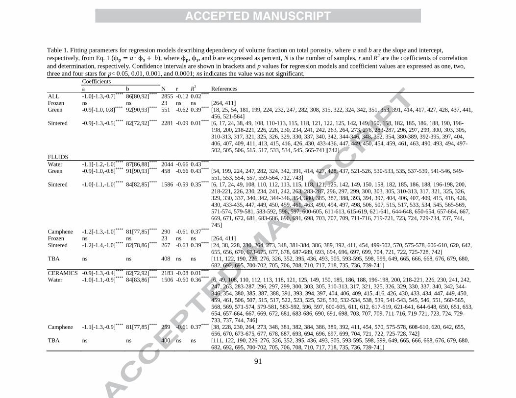
91
Table 1. Fitting parameters for regression models describing dependency of volume fraction on total porosity, where a and b are the slope and intercept,
respectively, from Eq. 1 ( ), where and b are expressed as percent, N is the number of samples, r and R2 are the coefficients of correlation
and determination, respectively. Confidence intervals are shown in brackets and p values for regression models and coefficient values are expressed as one, two,
three and four stars for p< 0.05, 0.01, 0.001, and 0.0001; ns indicates the value was not significant. Coefficients
N r R2 References a b
ALL -1.0[-1.3,-0.7]**** 86[80,92]**** 2855 -0.12 0.02**** Frozen ns ns 23 ns ns [264, 411] Green -0.9[-1.0, 0.8]**** 92[90,93]**** 551 -0.62 0.39**** [18, 25, 54, 181, 199, 224, 232, 247, 282, 308, 315, 322, 324, 342, 351, 353, 391, 414, 417, 427, 428, 437, 441,
456, 521-564] Sintered -0.9[-1.3,-0.5]****
82[72,92]**** 2281 -0.09 0.01**** [6, 17, 24, 38, 49, 108, 110-113, 115, 118, 121, 122, 125, 142, 149, 150, 158, 182, 185, 186, 188, 190, 196-
198, 200, 218-221, 226, 228, 230, 234, 241, 242, 263, 264, 273, 276, 283-287, 296, 297, 299, 300, 303, 305, 310-313, 317, 321, 325, 326, 329, 330, 337, 340, 342, 344-346, 348, 352, 354, 380-389, 392-395, 397, 404,
406, 407, 409, 411, 413, 415, 416, 426, 430, 433-436, 447, 449, 450, 454, 459, 461, 463, 490, 493, 494, 497-502, 505, 506, 515, 517, 533, 534, 545, 565-741][742]
FLUIDS
Water -1.1[-1.2,-1.0]**** 87[86,88]**** 2044 -0.66 0.43**** Green -0.9[-1.0,-0.8]**** 91[90,93]**** 458 -0.66 0.43**** [54, 199, 224, 247, 282, 324, 342, 391, 414, 427, 428, 437, 521-526, 530-533, 535, 537-539, 541-546, 549-
551, 553, 554, 557, 559-564, 712, 743] Sintered -1.0[-1.1,-1.0]**** 84[82,85]**** 1586 -0.59 0.35**** [6, 17, 24, 49, 108, 110, 112, 113, 115, 118, 121, 125, 142, 149, 150, 158, 182, 185, 186, 188, 196-198, 200,
218-221, 226, 230, 234, 241, 242, 263, 283-287, 296, 297, 299, 300, 303, 305, 310-313, 317, 321, 325, 326, 329, 330, 337, 340, 342, 344-346, 354, 380, 385, 387, 388, 393, 394, 397, 404, 406, 407, 409, 415, 416, 426, 430, 433-435, 447, 449, 450, 459, 461, 463, 490, 494, 497, 498, 506, 507, 515, 517, 533, 534, 545, 565-569, 571-574, 579-581, 583-592, 596, 597, 600-605, 611-613, 615-619, 621-641, 644-648, 650-654, 657-664, 667, 669, 671, 672, 681, 683-686, 690, 691, 698, 703, 707, 709, 711-716, 719-721, 723, 724, 729-734, 737, 744, 745]
Camphene -1.2[-1.3,-1.0]**** 81[77,85]**** 290 -0.61 0.37**** Frozen ns ns 23 ns ns [264, 411]
Sintered -1.2[-1.4,-1.0]**** 82[78,86]**** 267 -0.63 0.39**** [24, 38, 228, 230, 264, 273, 348, 381-384, 386, 389, 392, 411, 454, 499-502, 570, 575-578, 606-610, 620, 642, 655, 656, 670, 673-675, 677, 678, 687-689, 693, 694, 696, 697, 699, 704, 721, 722, 725-728, 742]
TBA ns ns 408 ns ns [111, 122, 190, 226, 276, 326, 352, 395, 436, 493, 505, 593-595, 598, 599, 649, 665, 666, 668, 676, 679, 680, 682, 692, 695, 700-702, 705, 706, 708, 710, 717, 718, 735, 736, 739-741]
CERAMICS -0.9[-1.3,-0.4]**** 82[72,92]**** 2183 -0.08 0.01**** Water -1.0[-1.1,-0.9]**** 84[83,86]**** 1506 -0.60 0.36**** [6, 49, 108, 110, 112, 113, 118, 121, 125, 149, 150, 185, 186, 188, 196-198, 200, 218-221, 226, 230, 241, 242,
247, 263, 283-287, 296, 297, 299, 300, 303, 305, 310-313, 317, 321, 325, 326, 329, 330, 337, 340, 342, 344-
346, 354, 380, 385, 387, 388, 391, 393, 394, 397, 404, 406, 409, 415, 416, 426, 430, 433, 434, 447, 449, 450, 459, 461, 506, 507, 515, 517, 522, 523, 525, 526, 530, 532-534, 538, 539, 541-543, 545, 546, 551, 560-565, 568, 569, 571-574, 579-581, 583-592, 596, 597, 600-605, 611, 612, 617-619, 621-641, 644-648, 650, 651, 653, 654, 657-664, 667, 669, 672, 681, 683-686, 690, 691, 698, 703, 707, 709, 711-716, 719-721, 723, 724, 729-733, 737, 744, 746]
Camphene -1.1[-1.3,-0.9]**** 81[77,85]**** 259 -0.61 0.37**** [38, 228, 230, 264, 273, 348, 381, 382, 384, 386, 389, 392, 411, 454, 570, 575-578, 608-610, 620, 642, 655, 656, 670, 673-675, 677, 678, 687, 693, 694, 696, 697, 699, 704, 721, 722, 725-728, 742]
TBA ns ns 400 ns ns [111, 122, 190, 226, 276, 326, 352, 395, 436, 493, 505, 593-595, 598, 599, 649, 665, 666, 668, 676, 679, 680,
682, 692, 695, 700-702, 705, 706, 708, 710, 717, 718, 735, 736, 739-741]

92
METALS -1.6[-1.9,-1.3]**** 88[82,94]**** 131 -0.72 0.51**** Water -1.6[-1.9,-1.3]**** 88[82,94]**** 104 -0.73 0.53**** [17, 142, 158, 182, 234, 407, 435, 463, 490, 494, 497, 498, 566, 567, 734] Camphene -1.6[-2.3,-0.9]**** 88[71,99]**** 27 -0.67 0.44**** [383, 499-502, 606, 607, 688, 689]
POLYMER -0.8[-0.9,-0.7]**** 93[92,95]**** 248 -0.62 0.38**** [181, 199, 232, 351, 353, 527-529, 547] Water -0.8[-0.9,-0.7]**** 95[94,96]**** 204 -0.77 0.59**** [54, 199, 224, 282, 324, 414, 427, 428, 437, 521, 524, 531, 535, 537, 543, 544, 549, 550, 553, 554, 557, 559,
743]
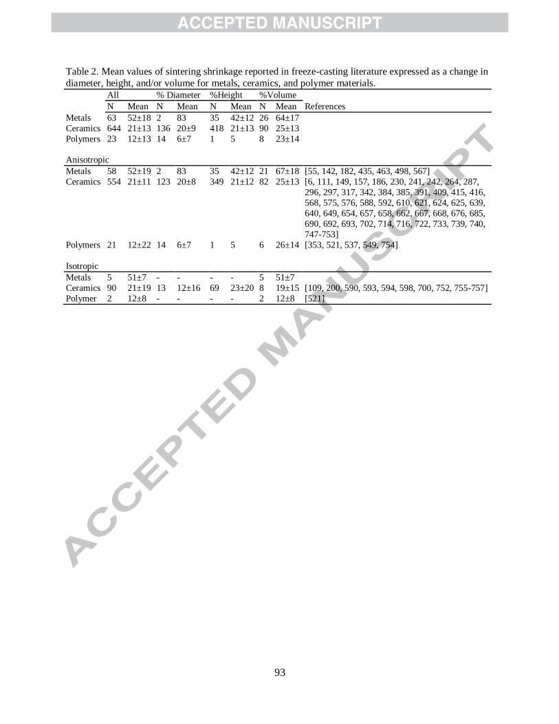
93
Table 2. Mean values of sintering shrinkage reported in freeze-casting literature expressed as a change in
diameter, height, and/or volume for metals, ceramics, and polymer materials.
All % Diameter %Height %Volume
References N Mean N Mean N Mean N Mean
Metals 63 52±18 2 83 35 42±12 26 64±17
Ceramics 644 21±13 136 20±9 418 21±13 90 25±13
Polymers 23 12±13 14 6±7 1 5 8 23±14
Anisotropic
Metals 58 52±19 2 83 35 42±12 21 67±18 [55, 142, 182, 435, 463, 498, 567]
Ceramics 554 21±11 123 20±8 349 21±12 82 25±13 [6, 111, 149, 157, 186, 230, 241, 242, 264, 287,
296, 297, 317, 342, 384, 385, 391, 409, 415, 416,
568, 575, 576, 588, 592, 610, 621, 624, 625, 639,
640, 649, 654, 657, 658, 662, 667, 668, 676, 685,
690, 692, 693, 702, 714, 716, 722, 733, 739, 740,
747-753]
Polymers 21 12±22 14 6±7 1 5 6 26±14 [353, 521, 537, 549, 754]
Isotropic
Metals
Ceramics
Polymer
5
90
2
51±7
21±19
12±8
-
13
-
-
12±16
-
-
69
-
-
23±20
-
5
8
2
51±7
19±15
12±8
[109, 200, 590, 593, 594, 598, 700, 752, 755-757]
[521]
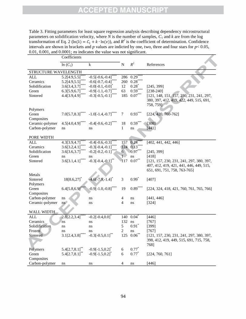
94
Table 3. Fitting parameters for least square regression analysis describing dependency microstructural
parameters on solidification velocity, where N is the number of samples, C1 and k are from the log transformation of Eq. 2 ( ), and R
2 is the coefficient of determination. Confidence
intervals are shown in brackets and p values are indicted by one, two, three and four stars for p< 0.05,
0.01, 0.001, and 0.0001; ns indicates the value was not significant.
Coefficients
N R2 References ln (C1) k
STRUCTURE WAVELENGTH
ALL 5.2[4.9,5.5]**** -0.5[-0.6,-0.4]**** 286 0.29****
Ceramics 5.2[4.9,5.5]**** -0.6[-0.7,-0.4]**** 260 0.28****
Solidification 3.6[3.4,3.7]**** -0.0[-0.1,-0.0]* 12 0.28* [245, 399]
Green 6.3[5.9,6.7]**** -0.9[-1.1,-0.7]**** 63 0.59**** [238-240]
Sintered 4.4[3.9,4.9]**** -0.3[-0.5,-0.1]**** 185 0.07*** [121, 148, 151, 157, 230, 231, 241, 297, 380, 397, 412, 419, 422, 449, 515, 691,
758, 759]
Polymers
Green 7.0[5.7,8.3]**** -1.0[-1.4,-0.7]**** 7 0.93*** [224, 420, 760-762]
Composites
Ceramic-polymer 4.5[4.0,4.9]**** -0.4[-0.6,-0.2]**** 18 0.59*** [308]
Carbon-polymer ns ns 1 ns [441]
PORE WIDTH
ALL 4.3[3.9,4.7]**** -0.4[-0.6,-0.3]**** 157 0.24**** [402, 441, 442, 446]
Ceramics 3.6[3.2,4.1]**** -0.3[-0.4,-0.1]**** 124 0.13****
Solidification 3.6[3.6,3.7]**** -0.2[-0.2,-0.1]**** 6 0.97*** [245, 399]
Green ns ns 1 ns [418]
Sintered 3.6[3.1,4.1]**** -0.3[-0.4,-0.1]** 117 0.07** [121, 157, 230, 231, 241, 297, 380, 397, 407, 412, 419, 421, 441, 446, 449, 515,
651, 691, 751, 758, 763-765]
Metals
Sintered 18[8.6,27]* -4.6[-7.9,-1.4]* 3 0.99* [407]
Polymers
Green 6.4[5.8,6.9]**** -0.9[-1.0,-0.8]**** 19 0.89**** [224, 324, 418, 421, 760, 761, 765, 766]
Composites
Carbon-polymer
Ceramic-polymer
ns
ns
ns
ns
4
4
ns
ns
[441, 446]
[324]
WALL WIDTH
ALL 2.8[2.2,3.4]**** -0.2[-0.4,0.0]* 140 0.04* [446]
Ceramics ns ns 132 ns [767] Solidification ns ns 5 0.91* [399]
Frozen ns ns 2 ns [767]
Sintered 3.1[2.4,3.8]**** -0.3[-0.5,0.1]** 125 0.06** [121, 157, 230, 231, 241, 297, 380, 397,
398, 412, 419, 449, 515, 691, 715, 758,
768]
Polymers 5.4[2.7,8.1]** -0.9[-1.5,0.2]* 6 0.77*
Green 5.4[2.7,8.1]** -0.9[-1.5,0.2]* 6 0.77* [224, 760, 761]
Composites
Carbon-polymer ns ns 4 ns [446]
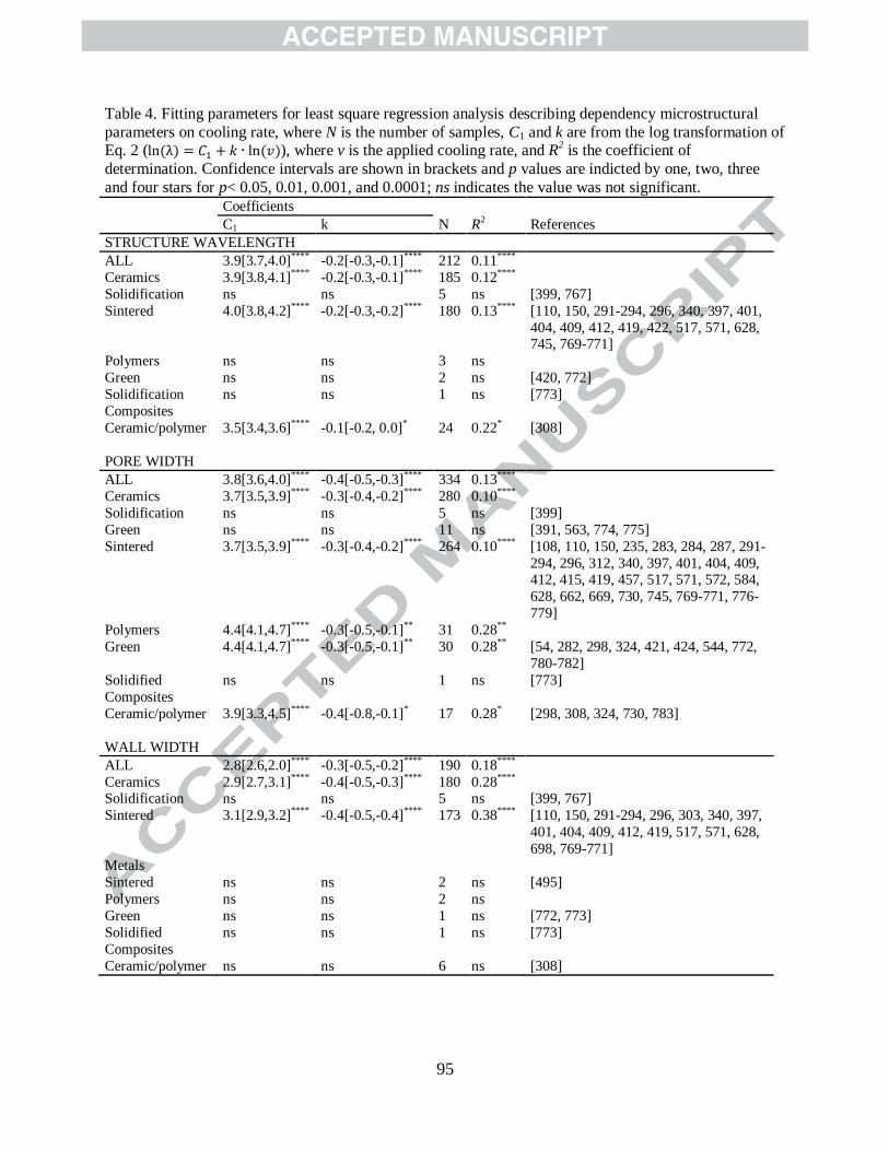
95
Table 4. Fitting parameters for least square regression analysis describing dependency microstructural
parameters on cooling rate, where N is the number of samples, C1 and k are from the log transformation of Eq. 2 ( ), where v is the applied cooling rate, and R
2 is the coefficient of
determination. Confidence intervals are shown in brackets and p values are indicted by one, two, three
and four stars for p< 0.05, 0.01, 0.001, and 0.0001; ns indicates the value was not significant.
Coefficients
N R2 References C1 k
STRUCTURE WAVELENGTH
ALL 3.9[3.7,4.0]**** -0.2[-0.3,-0.1]**** 212 0.11****
Ceramics 3.9[3.8,4.1]**** -0.2[-0.3,-0.1]**** 185 0.12****
Solidification ns ns 5 ns [399, 767]
Sintered 4.0[3.8,4.2]**** -0.2[-0.3,-0.2]**** 180 0.13**** [110, 150, 291-294, 296, 340, 397, 401,
404, 409, 412, 419, 422, 517, 571, 628, 745, 769-771]
Polymers ns ns 3 ns
Green ns ns 2 ns [420, 772]
Solidification ns ns 1 ns [773]
Composites
Ceramic/polymer 3.5[3.4,3.6]**** -0.1[-0.2, 0.0]* 24 0.22* [308]
PORE WIDTH
ALL 3.8[3.6,4.0]**** -0.4[-0.5,-0.3]**** 334 0.13****
Ceramics 3.7[3.5,3.9]**** -0.3[-0.4,-0.2]**** 280 0.10****
Solidification ns ns 5 ns [399]
Green ns ns 11 ns [391, 563, 774, 775]
Sintered 3.7[3.5,3.9]**** -0.3[-0.4,-0.2]**** 264 0.10**** [108, 110, 150, 235, 283, 284, 287, 291-
294, 296, 312, 340, 397, 401, 404, 409, 412, 415, 419, 457, 517, 571, 572, 584,
628, 662, 669, 730, 745, 769-771, 776-
779]
Polymers 4.4[4.1,4.7]**** -0.3[-0.5,-0.1]** 31 0.28**
Green 4.4[4.1,4.7]**** -0.3[-0.5,-0.1]** 30 0.28** [54, 282, 298, 324, 421, 424, 544, 772,
780-782]
Solidified ns ns 1 ns [773]
Composites
Ceramic/polymer 3.9[3.3,4.5]**** -0.4[-0.8,-0.1]* 17 0.28* [298, 308, 324, 730, 783]
WALL WIDTH
ALL 2.8[2.6,2.0]**** -0.3[-0.5,-0.2]**** 190 0.18****
Ceramics 2.9[2.7,3.1]**** -0.4[-0.5,-0.3]**** 180 0.28**** Solidification ns ns 5 ns [399, 767]
Sintered 3.1[2.9,3.2]**** -0.4[-0.5,-0.4]**** 173 0.38**** [110, 150, 291-294, 296, 303, 340, 397,
401, 404, 409, 412, 419, 517, 571, 628,
698, 769-771]
Metals
Sintered ns ns 2 ns [495]
Polymers ns ns 2 ns
Green ns ns 1 ns [772, 773]
Solidified ns ns 1 ns [773]
Composites
Ceramic/polymer ns ns 6 ns [308]
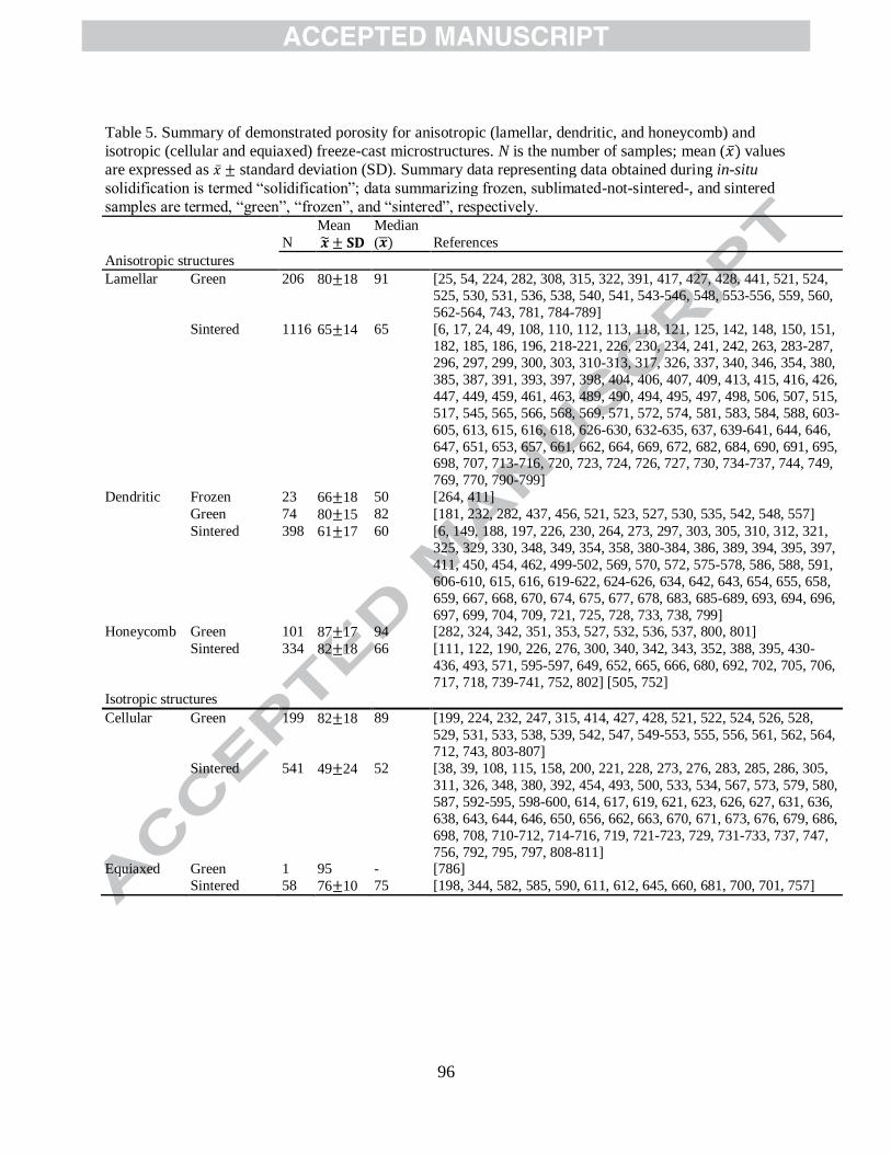
96
Table 5. Summary of demonstrated porosity for anisotropic (lamellar, dendritic, and honeycomb) and
isotropic (cellular and equiaxed) freeze-cast microstructures. N is the number of samples; mean ( values
are expressed as standard deviation (SD). Summary data representing data obtained during in-situ
solidification is termed “solidification”; data summarizing frozen, sublimated-not-sintered-, and sintered
samples are termed, “green”, “frozen”, and “sintered”, respectively.
N
Mean
Median
( References
Anisotropic structures
Lamellar Green 206 80 18 91 [25, 54, 224, 282, 308, 315, 322, 391, 417, 427, 428, 441, 521, 524,
525, 530, 531, 536, 538, 540, 541, 543-546, 548, 553-556, 559, 560,
562-564, 743, 781, 784-789]
Sintered 1116 65 14 65 [6, 17, 24, 49, 108, 110, 112, 113, 118, 121, 125, 142, 148, 150, 151,
182, 185, 186, 196, 218-221, 226, 230, 234, 241, 242, 263, 283-287,
296, 297, 299, 300, 303, 310-313, 317, 326, 337, 340, 346, 354, 380,
385, 387, 391, 393, 397, 398, 404, 406, 407, 409, 413, 415, 416, 426,
447, 449, 459, 461, 463, 489, 490, 494, 495, 497, 498, 506, 507, 515,
517, 545, 565, 566, 568, 569, 571, 572, 574, 581, 583, 584, 588, 603-
605, 613, 615, 616, 618, 626-630, 632-635, 637, 639-641, 644, 646,
647, 651, 653, 657, 661, 662, 664, 669, 672, 682, 684, 690, 691, 695, 698, 707, 713-716, 720, 723, 724, 726, 727, 730, 734-737, 744, 749,
769, 770, 790-799]
Dendritic Frozen 23 66 18 50 [264, 411]
Green 74 80 15 82 [181, 232, 282, 437, 456, 521, 523, 527, 530, 535, 542, 548, 557]
Sintered 398 61 17 60 [6, 149, 188, 197, 226, 230, 264, 273, 297, 303, 305, 310, 312, 321,
325, 329, 330, 348, 349, 354, 358, 380-384, 386, 389, 394, 395, 397,
411, 450, 454, 462, 499-502, 569, 570, 572, 575-578, 586, 588, 591,
606-610, 615, 616, 619-622, 624-626, 634, 642, 643, 654, 655, 658,
659, 667, 668, 670, 674, 675, 677, 678, 683, 685-689, 693, 694, 696,
697, 699, 704, 709, 721, 725, 728, 733, 738, 799] Honeycomb Green 101 87 17 94 [282, 324, 342, 351, 353, 527, 532, 536, 537, 800, 801]
Sintered 334 82 18 66 [111, 122, 190, 226, 276, 300, 340, 342, 343, 352, 388, 395, 430-
436, 493, 571, 595-597, 649, 652, 665, 666, 680, 692, 702, 705, 706,
717, 718, 739-741, 752, 802] [505, 752]
Isotropic structures
Cellular Green 199 82 18 89 [199, 224, 232, 247, 315, 414, 427, 428, 521, 522, 524, 526, 528,
529, 531, 533, 538, 539, 542, 547, 549-553, 555, 556, 561, 562, 564,
712, 743, 803-807]
Sintered 541 49 24 52 [38, 39, 108, 115, 158, 200, 221, 228, 273, 276, 283, 285, 286, 305,
311, 326, 348, 380, 392, 454, 493, 500, 533, 534, 567, 573, 579, 580,
587, 592-595, 598-600, 614, 617, 619, 621, 623, 626, 627, 631, 636,
638, 643, 644, 646, 650, 656, 662, 663, 670, 671, 673, 676, 679, 686,
698, 708, 710-712, 714-716, 719, 721-723, 729, 731-733, 737, 747,
756, 792, 795, 797, 808-811] Equiaxed Green 1 95 - [786]
Sintered 58 76 10 75 [198, 344, 582, 585, 590, 611, 612, 645, 660, 681, 700, 701, 757]

97
Table 6. Summary of demonstrated pore and wall width for anisotropic (lamellar, dendritic, and honeycomb) and
isotropic (cellular and equiaxed) freeze-cast microstructures. N is the number of samples; mean ( values are
expressed as standard deviation (SD). Summary data representing data obtained during in-situ solidification is
termed “solidification”; data summarizing frozen, sublimated-not-sintered-, and sintered samples are termed,
“green”, “frozen”, and “sintered”, respectively.
N
Mean
Median
( References
PORE WIDTH (μm)
Lamellar Solidification 8 29 13 31 [245, 399, 773, 812]
Green 221 73 90 42 [54, 156, 192, 224, 282, 288-290, 295, 298, 308, 315, 322, 391, 402, 418,
421, 424, 440-442, 446, 460, 521, 530, 531, 538, 540, 541, 544, 546, 553, 555, 559, 560, 563, 564, 743, 754, 760, 761, 765, 766, 772, 774, 775, 780-783, 785, 787, 789, 813-827]
Sintered 653 44 85 21 [6, 17, 24, 49, 55, 107, 108, 110, 112, 118, 121, 150, 157, 182, 185, 192, 218-221, 230, 231, 235, 241, 283-287, 291-294, 296, 297, 299, 300, 310, 312, 313, 340, 346, 354, 380, 397, 401, 404, 406, 407, 409, 412, 413, 415, 419, 426, 449, 457, 459, 461, 463, 489, 490, 494, 497, 515, 517, 545, 565, 566, 569, 571, 572, 584, 603, 604, 618, 628, 630, 634, 635, 639, 647, 651,
661, 662, 669, 672, 682, 691, 724, 726, 730, 734-736, 745, 749-751, 753, 758, 763, 764, 769-771, 776-779, 791, 797, 799, 828-837]
Dendritic Solidification 39 45 5 45 [2]
Frozen 22 86 45 75 [264, 411]
Green 31 17 20 7 [44, 52, 181, 282, 390, 521, 527, 542, 838-840]
Sintered 267 58 87 20 [6, 149, 188, 197, 230, 264, 297, 304, 310, 312, 321, 330, 349, 354, 358, 382, 383, 389, 394, 395, 397, 411, 419, 450, 454, 462, 499-501, 569, 570,
572, 577, 586, 606-609, 620-622, 634, 655, 658, 675, 677, 678, 687, 688, 693, 694, 696, 721, 728, 799, 833, 841-854]
Honeycomb Green 201 129 148 80 [1, 282, 314, 324, 350, 351, 353, 425, 429, 439, 460, 532, 800, 801, 817, 825, 855-864] [227, 815]
Sintered 101 44 60 21 [190, 225, 276, 300, 340, 352, 429-431, 433-436, 571, 595, 596, 649, 652, 665, 680, 692, 718, 751, 802] [505, 849]
Cellular Green 189 130 120 100 [68, 199, 224, 247, 315, 414, 418, 421, 438, 526, 528, 529, 531, 538, 539, 542, 547, 549-553, 555, 743, 783, 804-806, 815, 838, 855, 860, 865-877]
Sintered 136 87 15 [115, 200, 221, 228, 276, 285, 286, 500, 579, 595, 599, 614, 621, 623, 650, 663, 676, 679, 686, 708, 710, 712, 721, 722, 732, 747, 755, 797, 808, 878-886]
Equiaxed Green 6 43 39 29 [198, 345, 585, 611, 645, 681, 700, 701, 757]
Sintered 28 348 533 220
[317, 887]
WALL WIDTH (μm)
Lamellar Solidification 6 3 2 2 [399]
Frozen 2 23 11 23 [767]
Green 69 24 47 8 [224, 308, 315, 440, 446, 448, 460, 541, 555, 564, 743, 760, 761, 772, 773, 785, 789, 823, 888]
Sintered 404 17 24 10 [49, 110, 118, 121, 148, 150, 157, 230, 231, 241, 285, 291-294, 296, 297, 300, 340, 380, 397, 398, 401, 404, 406, 409, 412, 419, 449, 461, 463, 494, 495, 497, 498, 506, 515, 517, 569, 571, 628, 641, 644, 661, 691, 698, 715, 726, 734, 745, 749, 758, 768-771, 797, 828]
Dendritic Solidification 39 7 3 7 [2]
Sintered 30 31 67 8 [297, 358, 397, 419, 570, 655, 693, 694]
Honeycomb Green 13 3 3 3 [351, 353, 425, 460, 889, 890]
Sintered 39 18 24 10 [352, 430, 431, 434, 571, 595, 649]
Cellular Green 15 16 29 8 [315, 555, 804, 806, 865]
Sintered 19 50 63 25 [228, 493, 698, 712, 722, 797]
Equiaxed Green - - -
Sintered 8 95 11 98 [700, 701]

98
Table 7. Micromechanical model and regression parameters describing relationships between relative
density and compressive strength of freeze-cast metals. C2 and are from the log transformation of Eq. 6
(
); confidence intervals are shown in brackets and p values are indicted
by one, two, three and four stars for p<0.05, 0.01, 0.001, and 0.0001; ns indicates the value was not
significant. N is the number of samples, and R2 is the coefficient of determination.
Coefficients
N R2 References Model C2
ALL
Regression -0.34[-0.62,-0.05]* 1.6[1.3,1.9]**** 60 0.67****
Open-cell -0.45[-0.54,-0.36] 1.5 60 0.67****
Honeycomb -0.90[-1.00,-0.79] 1.0 60 0.57****
Relative density, < 0.5
Regression ns 1.7[1.3,2.2]**** 46 0.60**** [17, 142, 407, 463, 490, 494, 497-502, 606,
607, 688, 689] Open-cell -0.46[-0.57,-0.35] 1.5 46 0.60****
Honeycomb -0.96[-1.08,-0.84] 1.0 46 0.49****
Relative density, > 0.5
Regression -0.59[-1.04,-0.15]* 1.1[0.5,1.8]** 32 0.30** [142, 158, 407, 490, 494, 495, 498, 500, 502,
606, 607, 688, 689] Open-cell -0.35[-0.47,-0.23] 1.5 32 0.27**
Honeycomb -0.69[-0.80,-0.57] 1.0 32 0.30**
Bulk material compressive strength values (all units in MPa). CES Edupack [891] was utilized for the following
materials: Ti-6Al-4V (950), Fe (210 ), Ti-5wt.% W (910), and W (610). Remaining values were obtained from
literature: Ti (900 and 483 for 4.0 [17] and 0.4 [892] wt.% O2) and Cu (176 [835]).

99
Table 8. Micromechanical model and regression parameters describing relationships between relative
density and compressive strength of anisotropic and isotropic freeze-cast ceramics. C2 and are from the
log transformation of Eq. 6 (
); confidence intervals are shown in
brackets and p values are indicted by one, two, three and four stars for p<0.05, 0.01, 0.001, and 0.0001; ns indicates the value was not significant. N is the number of samples, and R
2 is the coefficient of
determination.
Coefficients
N R2 References Model C2 β1
ALL
Regression
-0.37[-0.51,-0.23]****
2.2[2.1,2.3]****
1032
0.59****
Open-cell -1.14[-1.20,-1.08] 1.5 1032 0.53****
Honeycomb -1.71[-1.78,-1.65] 1.0 1032 0.42****
ANISOTROPIC
Regression -0.24[-0.39,-0.01]** 2.3[2.1,2.4]**** 844 0.61****
Open-cell -1.12[-1.18,-1.06] 1.5 844 0.54****
Honeycomb -1.70[-1.78,-1.63] 1.0 844 0.42****
Lamellar [113, 118, 121, 150, 196, 220, 226, 241, 242, 283, 284, 286, 287, 296, 297, 303, 313, 337,
340, 380, 385, 387, 391, 406, 413, 415, 416,
447, 449, 461, 489, 506, 507, 515, 517, 565,
568, 571, 574, 581, 583, 626, 628-630, 635,
637, 639, 653, 657, 664, 669, 672, 684, 690,
691, 707, 713, 714, 723, 744, 749, 794, 797]
Regression ns 2.5[2.4,2.7]**** 481 0.63****
Open-cell -1.05[-1.13,-0.97] 1.5 481 0.52****
Honeycomb -1.62[-1.71,-1.53] 1.0 481 0.40****
Dendritic [197, 226, 264, 297, 303, 321, 325, 380-382,
386, 389, 411, 462, 577, 578, 586, 608-610,
619-622, 625, 626, 642, 654, 667, 668, 670,
674, 677, 683, 685, 693, 694, 699, 725, 728]
Regression -1.17[-1.52,-0.83]**** 1.6[1.3,1.9]**** 150 0.44****
Open-cell -1.27[-1.39,-1.14] 1.5 150 0.44****
Honeycomb -1.82[-1.95,-1.69] 1.0 150 0.39****
Honeycomb
[111, 226, 340, 342, 343, 352, 430-432, 493,
505, 571, 597, 649, 680, 692, 702, 705, 706,
739, 740, 752] [505, 752]
Regression ns 2.3[2.0,2.5]**** 207 0.67****
Open-cell -1.19[-1.33,-1.06] 1.5 207 0.59****
Honeycomb -1.82[-1.98,-1.66] 1.0 207 0.46****
ISOTROPIC
Regression -0.74[-1.06,-0.42]**** 2.0[1.7,2.2]**** 187 0.55****
Open-cell -1.25[-1.41,-1.08] 1.5 187 0.52****
Honeycomb -1.78[-1.96,-1.60] 1.5 187 0.41**** Cellular
[38, 39, 228, 286, 380, 392, 592, 617, 619,
621, 631, 636, 670, 673, 676, 679, 710, 714,
722, 723, 747, 756, 797, 811]
Regression -0.67[-1.00,-0.30]**** 2.0[1.7,2.4]**** 147 0.55****
Open-cell -1.23[-1.43,-1.03] 1.5 147 0.51****
Honeycomb -1.72[-1.94,-1.50] 1.5 147 0.40****
Equiaxed
[345, 585, 590, 611, 612, 660, 681, 700, 701] Regression -1.40[-2.16,-0.65]**** 1.4[0.9,1.9]**** 40 0.45****
Open-cell -1.30[-1.52,-1.07] 1.5 40 0.45****
Honeycomb -1.99[-2.23,-1.76] 1.5 40 0.41****
Bulk material flexural strength values (all units in MPa). CES Edupack [891] was utilized for the following materials: Al2O3 (400), biphasic calcium phosphate (BCP; 45), bioglass (110), calcium phosphate (55), hydroxyapatite (HAP; 120), yttria-stabilized zirconia (YSZ, 500), ZrO2 (460), Si3N4 (758), SiC (250), tricalcium phosphate (TCP; 45), TiO2 (180), SiAlON (800), CaSiO3 (100), whereas literature values were taken for: Y2SiO5 (116 [893]), ZrB2 (300 [894]), lead zirconate titanate (PZT; 90
[895]), Yb2SiO5 (150 [896]), Ca3ZrSiO9 (98 [897]), and mullite (240 [508]). Rule of mixtures, using the aforementioned values, was used to approximate values for mixed particle systems.
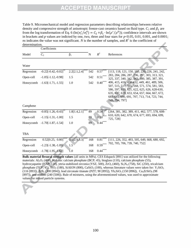
100
Table 9. Micromechanical model and regression parameters describing relationships between relative
density and compressive strength of anisotropic freeze-cast ceramics based on fluid type. C2 and are
from the log transformation of Eq. 6 (
); confidence intervals are shown
in brackets and p values are indicted by one, two, three and four stars for p<0.05, 0.01, 0.001, and 0.0001;
ns indicates the value was not significant. N is the number of samples, and R2 is the coefficient of
determination. Coefficients
N R2 References Model C2 β1
Water
Regression -0.22[-0.42,-0.02]** 2.2[2.1,2.4]**** 542 0.57**** [113, 118, 121, 150, 197, 220, 226, 241, 242,
283, 284, 286, 287, 296, 297, 303, 313, 321, 325, 337, 340, 342, 343, 380, 385, 387, 391,
406, 415, 416, 430-432, 449, 461, 489, 506,
507, 515, 517, 565, 568, 571, 574, 581, 583,
586, 597, 619, 621, 622, 625, 626, 628-630,
635, 637, 639, 653, 654, 657, 664, 667, 672,
683-685, 690, 691, 707, 713, 714, 723, 744,
749, 794, 797]
Open-cell -1.05[-1.12,-0.98] 1.5 542 0.51****
Honeycomb -1.63[-1.71,-1.55] 1.0 542 0.40****
Camphene
Regression -0.85[-1.26,-0.43]** 1.8[1.4,2.1]**** 89 0.54**** [264, 381, 382, 389, 411, 462, 577, 578, 608-
610, 620, 642, 670, 674, 677, 693, 694, 699,
725, 728] Open-cell -1.15[-1.31,-1.00] 1.5 89 0.53****
Honeycomb -1.70[-1.87,-1.54] 1.0 89 0.44****
TBA
Regression 0.52[0.25, 0.80]**** 3.1[2.9,3.3]**** 168 0.81**** [111, 226, 352, 493, 505, 649, 668, 680, 692,
702, 705, 706, 739, 740, 752] Open-cell -1.23[-1.38,-1.09] 1.5 168 0.59****
Honeycomb -1.78[-1.95,-1.62] 1.0 168 0.44****
Bulk material flexural strength values (all units in MPa). CES Edupack [891] was utilized for the following
materials: Al2O3 (400), biphasic calcium phosphate (BCP; 45), bioglass (110), calcium phosphate (55),
hydroxyapatite (HAP; 120), yttria-stabilized zirconia (YSZ, 500), ZrO2 (460), Si3N4 (758), SiC (250), tricalcium
phosphate (TCP; 45), TiO2 (180), SiAlON (800), CaSiO3 (100), whereas literature values were taken for: Y2SiO5
(116 [893]), ZrB2 (300 [894]), lead zirconate titanate (PZT; 90 [895]), Yb2SiO5 (150 [896]), Ca3ZrSiO9 (98 [897]), and mullite (240 [508]). Rule of mixtures, using the aforementioned values, was used to approximate
values for mixed particle systems.

101
Table 10. Regression models comparing model fits between Eq. 6 (
) and Eq. 7
(
) for anisotropic ceramic materials derived from particle suspensions using
tert-butyl alcohol (TBA), water, and camphene as the fluid. Eq. 6 describes normalized compressive
strength (
) of freeze-cast ceramics in terms of relative density and Eq. 7 also considers the
effect of test specimen aspect ratio (A). Confidence intervals for coefficients are shown in brackets and p
values are indicted by one, two, three and four stars for p<0.05, 0.01, 0.001, and 0.0001; ns indicates the
value was not significant; N is the number of samples, BIC is the Bayesian Information Criterion, and adj. R
2 is the adjusted coefficient of determination.
Model
Coefficients
N BIC adj.R2 Refs. C3 β1 β2
TBA
Eq. 8 0.7[0.4,0.9]**** 3.1[2.9,3.4]**** - 116
187 0.88**** [111, 226, 352, 493, 505,
649, 680, 692, 702, 705,
706] Eq. 10 ns 2.5[2.4,2.7]**** -1.0[-1.1,-0.9]**** 64 0.96****
Water
Eq. 8 ns 2.4[2.2,2.6] **** - 403
956 0.61**** [113, 121, 150, 197, 220,
226, 241, 242, 283, 284,
286, 287, 296, 297, 303,
313, 321, 337, 340, 342,
391, 406, 415, 416, 430,
431, 449, 461, 515, 517,
565, 571, 581, 583, 597,
619, 621, 622, 625, 628-
630, 635, 637, 653, 654,
672, 691, 707, 713, 749]
Eq. 10 ns 2.4[2.2,2.6] **** -0.4[-0.6,-0.1]** 952 0.62****
Camphene
Eq. 8 -0.8[-1.3,-0.4]**** 1.8[1.4,2.1] **** -
89
200 0.54**** [264, 381, 382, 389, 411, 462, 577, 578, 608-610,
620, 642, 670, 674, 677,
693, 694, 699, 725, 728]
Eq. 10 -0.5[-0.9,-0.2]** 2.1[1.8,2.5]**** 0.7[0.5, 1.0]*** 176 0.66****
Bulk material flexural strength values (all units in MPa). CES Edupack [891] was utilized for the following
materials: Al2O3 (400), biphasic calcium phosphate (BCP; 45), bioglass (110), calcium phosphate (55),
hydroxyapatite (HAP; 120), yttria-stabilized zirconia (YSZ, 500), ZrO2 (460), Si3N4 (758), SiC (250), tricalcium
phosphate (TCP; 45), TiO2 (180), SiAlON (800), CaSiO3 (100), whereas literature values were taken for: Y2SiO5
(116 [893]), ZrB2 (300 [894]), lead zirconate titanate (PZT; 90 [895]), Yb2SiO5 (150 [896]), Ca3ZrSiO9 (98 [897]),
and mullite (240 [508]). Rule of mixtures, using the aforementioned values, was used to approximate values for
mixed particle systems.

102
Fig. 1. Number of freeze-casting papers published in peer-reviewed journals per year, since
2000.
Fig. 2. Unidirectional freeze-casting process. A suspension consisting of particles (grey)
dispersed in a fluid (dark blue) is (a) placed onto a freezing substrate; after nucleation, (b)
dendrites (light blue) propagate in the direction of the thermal gradient while pushing particles
away from the moving front. An (c) accumulation region of rejected particles develops ahead of
the solid/liquid interface, inducing particle packing within interdendritic space. After (d)
complete solidification, the solidified fluid is (e) removed via sublimation leaving elongated
pores (white) which template the dendrites. In the case of ceramic and metallic materials, the
remaining particle scaffold is (f) sintered to densify particle-packed walls (black).
Fig. 3. Isotropic freeze-casting process. A suspension contained within a thermally insulating
mold is (a) placed in a cooled environment and (b) solid nucleation occurs randomly throughout
the suspension. After nucleation, (c) solid crystal growth occurs at random orientations
throughout the volume and no preferential growth direction is observed. The resulting pore
structures are nearly isotropic following (d) sublimation and (e) sintering.
Fig. 4. Schematic representation of the most commonly observed pore structures in freeze-cast
materials, including anisotropic (a) lamellar, (b) dendritic, and (c) elongated honeycomb, and (d)
cellular-honeycomb, (e) equiaxed, and (f) cellular pore structures. Here, the solid, colored
regions represent the morphology of the solidified fluid which, after removal, largely defines the
pore structure in the final material. The dark regions represent the particle-rich regions, which
form are templated during the solidification process. These particle-rich regions can be further
sintered into dense walls.
Fig. 5. FreezeCasting.net database schema. Primary tables (blue) contain citation data and assign
sample identification numbers for each processing condition explored by each individual paper.
Secondary tables (green) contain experimental data and the property tables (red) contain property
values for fluids, particles, additives, molds, and bulk materials. Lastly, the suspension stability
table (green) is a supplementary table that contains experimental data extracted from suspension
stabilization studies.
Fig. 6. Morphological transition of ice from lamellar to dendritic structures, where (a) a lamellar
morphology is depicted. The onset of dendritic side branching is shown in (b); these “secondary
arms” increase in both length and density (number of arms) (c), where the ice morphology has
completely transitioned from lamellar to dendritic. As side branching increases, the diameter of
the primary branch decreases. Although the morphological structure of ice is still dendritic in (d),
the resulting porous structure is likely to be cellular as a result of the highly interconnected ice
network that has formed.
Fig. 7. Effect of binder on anisotropic freeze-cast structures derived from aqueous suspensions.
Sintered alumina (Al2O3) with increasing amounts of binder, polyvinyl alcohol (PVA) [310] is
shown in (a-d). Cross-sections are taken parallel to the solidification direction; dark regions
represent pores and the light regions are sintered, Al2O3 walls; (a) shows the microstructure
obtained when no binder is added; the pore morphology is lamellar and one-sided secondary
dendritic features (red arrows) are present. Microstructures obtained with the inclusion of 5, 15,
and 20 wt.% PVA (with respect to Al2O3) are shown in (b) through (d), respectively. Non-
sintered tungsten disulfide (WS2) is shown in (e-i) [315]. The lamellar microstructure shown in

103
(e) is obtained with the inclusion of 1 wt.% gelatin (with respect to WS2); the binder content
increases to 2, 3, 4, and 5 wt.% in (f) through (h).
Fig. 8. Effect of isopropyl alcohol (IPA) additives on anisotropic freeze-cast microstructures
derived from aqueous suspensions. These microstructural cross-sections are taken parallel to the
solidification direction; (a) shows sintered 10 vol.% TiO2 [296] obtained without IPA, and (b) -
(d) with the addition of 1, 5, and 30 vol.% IPA (with respect to fluid volume).
Fig. 9. Effect of glycerol on anisotropic freeze-cast microstructures derived from aqueous
suspensions. The lamellar structure in (a) was obtained after sintering microstructures templated
using aqueous suspensions of 10 vol.% HAP [286]. In (b), 20 wt.% glycerol (with respect to
water) was added to the initial suspension; the resulting microstructure consists of lamellar walls
joined by bridges that form nearly perpendicular to, and join, the walls. Red arrows indicate the
direction of freezing.
Fig. 10. Non-standard pore structures obtained using aqueous suspensions. The sintered
honeycomb structures shown in (a) are obtained with the addition of a zirconium acetate
complex (ZRA) for zirconia [225], whereas (b) was obtained for 5 wt.% gelatin [282];
anisotropic freezing was used for both radial cross-sections in (a) and (b). The equiaxed
structures shown in (c) and (d) were both obtained by employing isotropic freezing techniques.
In (c), air entrapped during the tumbling step was responsible for templating the equiaxed
macropores in the sintered silica [198] material, whereas polystyrene space-holders were used
for the sintered mullite foam [344] shown in (d).
Fig. 11. Overview of microstructures obtained using non-aqueous fluids under directional
freezing conditions. Red arrows indicate the direction of freezing for cross-sections taken
parallel to the solidification direction; cross-sections taken perpendicular to the solidification
direction are marked with a circle. Dendritic structures are shown in (a-c), where (a) is sintered,
50 vol.% Al2O3 templated with camphene [348], (b) is sintered, 20 wt.% silicon oxycarbide
(SiOC) obtained using cyclohexane, and (c) is polyurethane templated with dioxane [181].
Honeycomb structures are shown in (d-f), where (d) is 30 wt.% polystyrene obtained with a fluid
mixture of polyethylene glycol and dioxane [350], (e) is sintered 10 vol.% Al2O3-ZrO2 obtained
using tert-butyl alcohol [352], and (f) is poly (L-lactic acid) obtained using dimethyl sulfoxide
(DMSO) [353].
Fig. 12. Dependency of zeta potential on (a) suspension pH and (b) amount of dispersant (wt.%,
relative to particle dry mass) for aqueous suspensions of alumina [305, 354-368, 898]. Data point
colors are mapped by dispersant weight percent, ranging from < 1 wt.% (violet) to 6 wt.% (red);
white data points indicate no dispersant was used. Plot created via the FreezeCasting.net open-
data repository.
Fig. 13. Plot showing dependence of total porosity on particle volume fraction within the
suspension (all volume fraction~porosity data from the FreezeCasting.net database included).
Data points that describe sintered samples are colored based on relative point-density (red circles
indicate high density regions and purple circles represent low density regions of the plot,
whereas data points that describe green samples (sublimated, not sintered) are shown with white
circles [6, 17, 18, 24, 25, 38, 49, 54, 108, 110-113, 115, 118, 121, 122, 125, 142, 149, 150, 158,
181, 182, 185, 186, 188, 190, 196-200, 218-221, 224, 226, 228, 230, 232, 234, 241, 242, 247,
263, 264, 273, 276, 282-287, 296, 297, 299, 303, 305, 308, 310-313, 315, 317, 321, 322, 324-
326, 329, 330, 337, 340, 342, 344-346, 348, 351-354, 380-389, 391-395, 397, 404, 406, 407,

104
409, 411, 413-417, 426-428, 430, 433-437, 441, 447, 449, 450, 454, 456, 459, 461, 463, 490,
493, 494, 497-502, 505-507, 515, 517, 521-557, 559-572, 574-581, 583-738, 740, 741, 743, 744,
827]. The solid line is obtained by fitting all data to Eq. 1 (% = -1.0±0.3 + 86%±6%;
N = 2,855, r = -0.12, R2 = 0.01, p < 0.0001), whereas the long- and short-dashed lines are
obtained by fitting green (N=551) and sintered (N=2,281) data, respectively. The grey, shaded
regions represent the 95% confidence interval about the regression lines. When only data
obtained from green (sublimated, not sintered) samples is considered, the fit to Eq. 1 improves
and ~40% variance in porosity is predicted by Eq. 1 (Table 1). Plot created via the
FreezeCasting.net open-data repository.
Fig. 14. Plots of total porosity vs. particle volume fraction categorized by fluid type (irrespective
of material type), where (a) is water (N=2,040), (b) is camphene (N=290), and (c) is tert-butyl
alcohol (N=411). In (a), data obtained from non-sintered samples are shown with white circles
[54, 199, 224, 247, 282, 324, 342, 391, 414, 427, 428, 437, 521-526, 530-533, 535, 537-539,
541-546, 549-551, 553, 554, 557, 559-564, 712, 743], and blue circles represent sintered samples
[6, 17, 24, 49, 108, 110, 112, 113, 115, 118, 121, 125, 142, 149, 150, 158, 182, 185, 186, 188,
196-198, 200, 218-221, 226, 230, 234, 241, 242, 263, 283-287, 296, 297, 299, 300, 303, 305,
310-313, 317, 321, 325, 326, 329, 330, 337, 340, 342, 344-346, 354, 380, 385, 387, 388, 393,
394, 397, 404, 406, 407, 409, 415, 416, 426, 430, 433-435, 447, 449, 450, 459, 461, 463, 490,
494, 497, 498, 506, 507, 515, 517, 533, 534, 545, 565-569, 571-574, 579-581, 583-592, 596,
597, 600-605, 611-613, 615-619, 621-641, 644-648, 650-654, 657-664, 667, 669, 671, 672, 681,
683-686, 690, 691, 698, 703, 707, 709, 711-716, 719-721, 723, 724, 729-734, 737, 744, 745].
Porosity data for camphene suspensions shown in (b) as white stars [264, 411] represent data
obtained from frozen samples; sintered data are red circles [24, 38, 228, 230, 264, 273, 348, 381-
384, 386, 389, 392, 411, 454, 499-502, 570, 575-578, 606-610, 620, 642, 655, 656, 670, 673-
675, 677, 678, 687-689, 693, 694, 696, 697, 699, 704, 721, 722, 725-728, 742]. All data in (c)
were obtained from sintered samples [111, 122, 190, 226, 276, 326, 352, 395, 436, 493, 505,
593-595, 598, 599, 649, 665, 666, 668, 676, 679, 680, 682, 692, 695, 700-702, 705, 706, 708,
710, 717, 718, 735, 736, 739-741]. Solid lines are obtained using least squares regression
(coefficients provided in Table 1); the shaded region and dotted lines represent the 95%
confidence interval and upper and lower boundaries of the 95% prediction region, respectively. Plot created via the FreezeCasting.net open-data repository.
Fig. 15. Plot of total porosity vs. particle volume fraction for aqueous suspensions categorized by
material type. Sintered samples are shown in red for (a) metals (N=131, [17, 142, 158, 182, 234,
407, 435, 463, 490, 494, 497, 498, 566, 567, 734]), blue for (b) ceramics (N=2,185, [6, 49, 108,
110, 112, 113, 118, 121, 125, 149, 150, 185, 186, 188, 196-198, 200, 218-221, 226, 230, 241,
242, 247, 263, 283-287, 296, 297, 299, 300, 303, 305, 310-313, 317, 321, 325, 326, 329, 330,
337, 340, 342, 344-346, 354, 380, 385, 387, 388, 391, 393, 394, 397, 404, 406, 409, 415, 416,
426, 430, 433, 434, 447, 449, 450, 459, 461, 506, 507, 515, 517, 522, 523, 525, 526, 530, 532-
534, 538, 539, 541-543, 545, 546, 551, 560-565, 568, 569, 571-574, 579-581, 583-592, 596, 597,
600-605, 611, 612, 617-619, 621-641, 644-648, 650, 651, 653, 654, 657-664, 667, 669, 672, 681,
683-686, 690, 691, 698, 703, 707, 709, 711-716, 719-721, 723, 724, 729-733, 737, 744, 746]),
and green for (c) polymers (N=248, [54, 199, 224, 282, 324, 414, 427, 428, 437, 521, 524, 531,
535, 537, 543, 544, 549, 550, 553, 554, 557, 559, 743]). Non-sintered samples are shown as
white circles in (b); all data points in (c) describe non-sintered materials. Solid lines are obtained
using least squares regression (coefficients provided in Table 1); the shaded region and dotted

105
lines represent the 95% confidence interval and upper and lower boundaries of the 95%
prediction region, respectively. Plot created via the FreezeCasting.net open-data repository.
Fig. 16. Box plot summarizing sintering shrinkage data measured as change in diameter, height
or volume for metals (red, N=63; [55, 142, 182, 435, 463, 498, 567]), ceramics (blue, N=644; [6,
111, 149, 157, 186, 230, 241, 242, 264, 287, 296, 297, 317, 342, 384, 385, 391, 409, 415, 416,
568, 575, 576, 588, 592, 610, 621, 624, 625, 639, 640, 649, 654, 657, 658, 662, 667, 668, 676,
685, 690, 692, 693, 702, 714, 716, 722, 733, 739, 740, 747-753]), and polymers (green, N=23;
[353, 521, 537, 549, 754]). The mean for each condition is shown as a black diamond, the
median as a black bar; outliers are shown as +, and error bars are derived using standard
deviation; boxes extend from lower to upper quartile values. Plot created via the
FreezeCasting.net open-data repository.
Fig. 17. Dependency of microstructural parameters on solidification velocity for materials
exhibiting lamellar pore structures, including: (a) structure wavelength (ceramics, sintered;
N=185, [121, 148, 151, 157, 230, 231, 241, 297, 380, 397, 412, 419, 422, 449, 515, 691, 758,
759], green; N=63, [238-240], and in-situ; N=12, [245, 399]; polymers; N=7, [224, 420, 760-
762]; ceramic/polymer composites; N=18 [308]; carbon/polymer composites; N=1, [441]), (b)
pore width (ceramics, sintered; N=117, [121, 157, 230, 231, 241, 297, 380, 397, 407, 412, 419,
421, 441, 446, 449, 515, 651, 691, 751, 758, 763-765], green; N=1, [418], and in-situ; N=6, [245,
399, 812]; polymers; N=19, [268, 302, 356, 359, 700, 701, 709, 710; metals; N=3, [407];
ceramic/polymer; N=4, [324]; carbon/polymer; N=4, [441, 446]), and (c) wall width (ceramics,
sintered; N=125, [121, 157, 230, 231, 241, 297, 380, 397, 398, 412, 419, 449, 515, 691, 715,
758, 768], frozen; N=2, [767], in-situ; N=5, [399]; polymers; N=6, [224, 760, 761];
carbon/polymer; N=4, [446]). Ceramics, polymers, metals, and ceramic/polymer composites are
shown in blue, green, red, and purple, respectively. Data obtained from sintered samples are
shown in as ○, non-sintered as +, and data obtained from in-situ investigations as ☆, and frozen
as △. Solid lines are obtained using least squares regression (coefficients provided in Table 3);
the shaded region and dotted lines represent the 95% confidence interval and upper and lower
boundaries of the 95% prediction region, respectively. Plot created via the FreezeCasting.net
open-data repository.
Fig. 18. Plot showing pore width at corresponding heights for samples directionally solidified
using a constant substrate temperature [192, 231, 404-407]. Data obtained from samples of
aqueous suspensions are shown as circles; camphene suspensions are shown as triangles. Plot
created via the FreezeCasting.net open-data repository.
Fig. 19. Plots showing pore width at corresponding heights for samples directionally solidified
using (a) linear cooling rates ≤ 5 K/min [308, 404, 411], (b) linear cooling rates ≥ 5 K/min [308,
404, 411], and (c) double-sided cooling with a linear cooling rate [239, 412]. Data obtained from
samples of aqueous suspensions are shown as circles; camphene suspensions are shown as
triangles. In (c), teal, diamond-shaped data points describe data obtained from green samples
derived from aqueous suspensions [239]. All other data points represent sintered samples. Plot
created via the FreezeCasting.net open-data repository.
Fig. 20. Dependency of microstructural parameters on cooling rate for materials exhibiting
lamellar pore structures, including: (a) structure wavelength (ceramics, sintered; N=180, [110,
150, 291-294, 296, 340, 397, 401, 404, 409, 412, 419, 422, 517, 571, 628, 745, 769-771], and in-
situ; N=5, [399, 767]; polymers, green; N=2, [420, 772] and in-situ; N=1, [773]; ceramic/polymer

106
composites; N=24, [308]), (b) pore width (ceramics, sintered; N=258, [108, 110, 150, 235, 283,
284, 287, 291-294, 296, 312, 340, 397, 401, 404, 409, 412, 415, 419, 457, 517, 571, 572, 584,
628, 662, 669, 730, 745, 769-771, 776-779], green; N=11, [391, 563, 774, 775], and in-situ; N=5,
[399]; polymers, green; N=30, [54, 282, 298, 324, 421, 424, 544, 772, 780-782] and in-situ; N=1,
[773]; ceramic/polymer composites; N=17, [298, 308, 324, 730, 783]), and (c) wall width
(ceramics, sintered; N=173, [110, 150, 291-294, 296, 303, 340, 397, 401, 404, 409, 412, 419,
517, 571, 628, 698, 769-771] and in-situ [399, 767]; polymers, green [772, 773] and in-situ; N=5,
[773]; metals; N=2, [495]; ceramic/polymer; N=6, [308]). Ceramics, polymers, metals, and
ceramic/polymer composites are shown in blue, green, red, and purple, respectively. Data
obtained from sintered samples are shown in as ○, non-sintered as +, and data obtained from in-
situ investigations as ☆, and frozen as △. Solid lines are obtained using least squares regression
(coefficients provided in Table 4); the shaded region and dotted lines represent the 95%
confidence interval and upper and lower boundaries of the prediction region, respectively. Plot
created via the FreezeCasting.net open-data repository.
Fig. 21. Plots showing pore width at corresponding heights for aqueous suspensions directionally
solidified using the (a) gap method [297], (b) exponential (tricalcium phosphate; TCP) [241], and
(c) parabolic [450] cooling functions for achieving constant velocities. Plot created via the
FreezeCasting.net open-data repository.
Fig. 22. (a) Plot of freezing temperature as a function of particle volume fraction. Data points for
studies using dissolved polymer [405, 409, 414, 421] and suspended particles [25, 221, 226, 312,
455-457] are shown as circles and diamonds, respectively. Dotted lines are calculated for
predicted freezing temperature for 2 and 5 nm particles (as marked) using the expression for
thermodynamic freezing temperature (Eq. 3). (b) Plot of undercooling as a function of particle
volume fraction. The solid line is obtained using least squares regression ( ), the shaded region and dotted lines represent the 95% confidence interval and upper and
lower boundaries of the 95% prediction region, respectively. Plot created via the
FreezeCasting.net open-data repository.
Fig. 23. Box plots showing range of demonstrated porosity for (a) anisotropic and (b) isotropic
freeze-cast materials, including: (a) lamellar (sintered, N =1,116 [6, 17, 24, 49, 108, 110, 112,
113, 118, 121, 125, 142, 148, 150, 151, 182, 185, 186, 196, 218-221, 226, 230, 234, 241, 242,
263, 283-287, 296, 297, 299, 300, 303, 310-313, 317, 326, 337, 340, 346, 354, 380, 385, 387,
391, 393, 397, 398, 404, 406, 407, 409, 413, 415, 416, 426, 447, 449, 459, 461, 463, 489, 490,
494, 495, 497, 498, 506, 507, 515, 517, 545, 565, 566, 568, 569, 571, 572, 574, 581, 583, 584,
588, 603-605, 613, 615, 616, 618, 626-630, 632-635, 637, 639-641, 644, 646, 647, 651, 653,
657, 661, 662, 664, 669, 672, 682, 684, 690, 691, 695, 698, 707, 713-716, 720, 723, 724, 726,
727, 730, 734-737, 744, 749, 769, 770, 790-799]; green, N =206 [25, 54, 224, 282, 308, 315,
322, 391, 417, 427, 428, 441, 521, 524, 525, 530, 531, 536, 538, 540, 541, 543-546, 548, 553-
556, 559, 560, 562-564, 743, 781, 784-789]), dendritic (sintered, N =398 [6, 149, 188, 197, 226,
230, 264, 273, 297, 303, 305, 310, 312, 321, 325, 329, 330, 348, 349, 354, 358, 380-384, 386,
389, 394, 395, 397, 411, 450, 454, 462, 499-502, 569, 570, 572, 575-578, 586, 588, 591, 606-
610, 615, 616, 619-622, 624-626, 634, 642, 643, 654, 655, 658, 659, 667, 668, 670, 674, 675,
677, 678, 683, 685-689, 693, 694, 696, 697, 699, 704, 709, 721, 725, 728, 733, 738, 799]; green,
N=74 [181, 232, 282, 437, 456, 521, 523, 527, 530, 535, 542, 548, 557]), and honeycomb
(sintered, N =334 [111, 122, 190, 226, 276, 300, 340, 342, 343, 352, 388, 395, 430-436, 493,
571, 595-597, 649, 652, 665, 666, 680, 692, 702, 705, 706, 717, 718, 739-741, 752, 802] [505,

107
849]); green, N=01 [282, 324, 342, 351, 353, 527, 532, 536, 537, 800, 801]) and (b) cellular
(sintered, N=541 [115, 200, 221, 228, 276, 285, 286, 500, 579, 595, 599, 614, 621, 623, 650,
663, 676, 679, 686, 708, 710, 712, 721, 722, 732, 747, 755, 797, 808, 878-886]; green, N=199
[68, 199, 224, 247, 315, 414, 418, 421, 438, 526, 528, 529, 531, 538, 539, 542, 547, 549-553,
555, 743, 783, 804-806, 838, 855, 860, 865-877]), and equiaxed (sintered N=58 [198, 345, 585,
611, 645, 681, 700, 701, 757]; green, N=1 [786]) pore structures. The mean for each condition is
shown as a black diamond, the median as a black bar; outliers are shown as +, and error bars are
derived using standard deviation; boxes extend from lower to upper quartile values. Plot created
via the FreezeCasting.net open-data repository.
Fig. 24. Box plots showing range of measured (a) pore and (b) wall widths for anisotropic freeze-
cast materials; full distributions are shown in (a) and (b), whereas (c) shows distribution for pore
width < 100 um and (d) shows distribution for wall width < 30 um; these include: (a) pore width:
lamellar (sintered, N =653 [6, 17, 24, 49, 55, 107, 108, 110, 112, 118, 121, 150, 157, 182, 185,
192, 218-221, 230, 231, 235, 241, 283-287, 291-294, 296, 297, 299, 300, 310, 312, 313, 340,
346, 354, 380, 397, 401, 404, 406, 407, 409, 412, 413, 415, 419, 426, 449, 457, 459, 461, 463,
489, 490, 494, 497, 515, 517, 545, 565, 566, 569, 571, 572, 584, 603, 604, 618, 628, 630, 634,
635, 639, 647, 651, 661, 662, 669, 672, 682, 691, 724, 726, 730, 734-736, 745, 749-751, 753,
758, 763, 764, 769-771, 776-779, 791, 797, 799, 828-837]; green, N =221 [54, 156, 192, 224,
282, 288-290, 295, 298, 308, 315, 322, 391, 402, 418, 421, 424, 440-442, 446, 460, 521, 530,
531, 538, 540, 541, 544, 546, 553, 555, 559, 560, 563, 564, 743, 754, 760, 761, 765, 766, 772,
774, 775, 780-783, 785, 787, 789, 813-827]), dendritic (sintered, N =267 [6, 149, 188, 197, 230,
264, 297, 304, 310, 312, 321, 330, 349, 354, 358, 382, 383, 389, 394, 395, 397, 411, 419, 450,
454, 462, 499-501, 569, 570, 572, 577, 586, 606-609, 620-622, 634, 655, 658, 675, 677, 678,
687, 688, 693, 694, 696, 721, 728, 799, 833, 841-854]; green, N =31 [44, 52, 181, 282, 390, 521,
527, 542, 838-840]), and honeycomb (sintered, N =101 [190, 225, 276, 300, 340, 352, 429-431,
433-436, 571, 595, 596, 649, 652, 665, 680, 692, 718, 751, 802]; green, N =201 [1, 282, 314,
324, 350, 351, 353, 425, 429, 439, 460, 532, 800, 801, 817, 825, 855-864]), (b) wall width,
including: lamellar (sintered, N =404 [49, 110, 118, 121, 148, 150, 157, 230, 231, 241, 285, 291-
294, 296, 297, 300, 340, 380, 397, 398, 401, 404, 406, 409, 412, 419, 449, 461, 463, 494, 495,
497, 498, 506, 515, 517, 569, 571, 628, 641, 644, 661, 691, 698, 715, 726, 734, 745, 749, 758,
768-771, 797, 828]; green, N =69 [224, 308, 315, 440, 446, 448, 460, 541, 555, 564, 743, 760,
761, 772, 773, 785, 789, 823, 888]), dendritic (sintered, N =30 [297, 358, 397, 419, 570, 655,
693, 694]), and honeycomb (sintered, N =39 [352, 430, 431, 434, 571, 595, 649]; green, N =13
[351, 353, 425, 460, 889, 890]). The mean for each condition is shown as a black diamond, the
median as a black bar; outliers are shown as +, and error bars are derived using standard
deviation; boxes extend from lower to upper quartile values. Plot created via the
FreezeCasting.net open-data repository.
Fig. 25. Point density plots showing microstructural parameters in freeze-cast materials: (a) pore
width vs. porosity [6, 17, 24, 49, 54, 108, 110, 112, 115, 118, 121, 149, 150, 181, 182, 185, 188,
190, 197-200, 218-221, 223, 224, 228, 230, 241, 247, 264, 276, 282-287, 296, 297, 300, 308,
310, 312, 313, 315, 321, 322, 330, 340, 345, 346, 349, 351-354, 358, 380, 382, 383, 389, 391,
394, 395, 397, 406, 407, 409, 411, 413-415, 426, 430, 431, 433-436, 441, 449, 450, 459, 461-
463, 489, 490, 494, 497, 499-501, 515, 517, 521, 526-532, 538-542, 544-547, 549-553, 555, 558-
560, 563-566, 569-572, 577, 584-586, 595, 596, 599, 603, 604, 606-609, 611, 614, 618, 620-623,
628, 630, 634, 635, 639, 645, 647, 649-652, 655, 658, 661-663, 665, 669, 672, 675-682, 686-
688, 691-694, 696, 700, 701, 708, 710, 712, 718, 721, 722, 724, 726, 728, 730, 732, 734-736,

108
747, 749, 769, 770, 787, 789, 791, 797, 799-801, 804-806, 808], (b) wall widths vs. porosity [49,
110, 118, 121, 150, 224, 228, 230, 241, 285, 296, 297, 300, 308, 315, 351-353, 358, 380, 397,
406, 409, 430, 431, 434, 449, 461, 463, 493-495, 497, 498, 506, 515, 517, 541, 558, 569-571,
595, 606, 628, 641, 644, 649, 655, 661, 691, 693, 694, 698, 700, 701, 712, 715, 722, 726, 734,
749, 769, 770, 789, 797, 804, 806] and (c) wall widths vs. pore widths [2, 49, 107, 110, 118, 121,
150, 157, 224, 228, 230, 231, 241, 285, 291-294, 296, 297, 300, 308, 312, 315, 340, 351-353,
358, 380, 397, 399, 401, 406, 409, 412, 419, 425, 430, 431, 434, 440, 449, 460, 461, 463, 494,
497, 505, 515, 517, 541, 555, 558, 569-571, 595, 606, 628, 649, 661, 691, 693, 694, 700, 701,
712, 722, 726, 734, 745, 749, 758, 760, 761, 769-773, 785, 789, 797, 804, 806, 813, 823, 828,
849, 865]. Points are colored based on relative point-density; red points indicate high density
regions and purple points represent low density regions. Plot created via the FreezeCasting.net
open-data repository.
Fig. 26. Anisotropic compressive properties observed for freeze-cast materials (irrespective of
pore structure). The insert (after ref. [463]) shows the loading direction for compressive strength
taken parallel and perpendicular to the wall direction. The box plot on the right shows the
distribution of reported ratios of compressive strength taken parallel and perpendicular to the
wall direction (
) including (red) metals [17, 407, 463, 490, 606], (blue) ceramics [148, 150,
264, 286, 303, 337, 404, 462, 493, 577, 635], and (green) poymers [353, 521, 524, 554]. The
mean for each condition is shown as a black diamond, the median as a black bar; outliers are
shown as +, and error bars are derived using standard deviation; boxes extend from lower to
upper quartile values. Plot created via the FreezeCasting.net open-data repository.
Fig. 27. Normalized longitudinal compressive strength of freeze-cast, sintered metals as a
function of relative density (1 - ). All materials resulting from aqueous particle suspensions
(circles) show lamellar pore structures; these include: Ti [17, 158, 490, 494, 495], Ti-6Al-4V
[407], Ti-5wt.%W [158, 495], Cu [463], Fe [497], and W [498]. All materials employing
camphene (diamonds) as the fluid exhibited dendritic microstructures; these are: Ti [499-501]
and Ti-6Al-4V [502]. The linear regression line (N = 60, R2 = 0.67, p < 0.0001) is shown as a
solid black line; the shaded region about the regression line represents the 95% confidence
interval about the regression line. Curve fittings for open-cell and honeycomb models (Eq. 5) are
shown as long and short-dashed lines, respectively. Equation coefficients and bulk material
strength ( ) are provided in Table 7. Plot created via the FreezeCasting.net open-data
repository.
Fig. 28. Normalized compressive strength of freeze-cast ceramics as a function of relative
density (1 - ); anisotropic (parallel loading) and isotropic structures are shown as blue circles
and yellow triangles, respectively [38, 39, 111, 113, 118, 121, 150, 190, 196, 197, 220, 226, 228,
241, 242, 264, 283, 284, 286, 287, 296, 297, 303, 313, 321, 325, 337, 340, 342, 343, 345, 352,
380-382, 385-387, 389, 391, 392, 406, 411, 413, 415, 416, 430-432, 447, 449, 462, 489, 493,
505-507, 515, 517, 565, 568, 571, 574, 577, 578, 581, 583, 585, 586, 590, 592, 597, 608-612,
617, 619-622, 625, 626, 628-631, 635-637, 639, 642, 649, 653, 654, 657, 660, 664, 667-670,
672-674, 676, 677, 679-681, 683-685, 690-694, 699-702, 705-707, 710, 713, 714, 718, 722, 723,
725, 728, 744, 747, 749, 752, 756, 794, 797, 811] [483]. The linear regression line for all
materials is shown as a solid black line (N=1,032, R2=0.59, p<0.0001); blue and yellow lines
represent anisotropic and isotropic materials, respectively. The shaded region about the
regression line represents the 95% confidence interval about the regression line, whereas the
dashed line of similar color represents the 95% prediction region. Curve fittings for open-cell

109
and honeycomb models (Eq. 5) are shown as horizontal and vertical dashed lines, respectively.
Coefficients and bulk material values of are provided in Table 8. Plot created via the
FreezeCasting.net open-data repository.
Fig. 29. Plots of normalized compressive strength of freeze-cast ceramics as a function of
relative density (1 - ), categorized by pore structure, including: (a) lamellar (N=492 [113, 118,
121, 150, 196, 220, 226, 241, 242, 283, 284, 286, 287, 296, 297, 303, 313, 337, 340, 380, 385,
387, 391, 406, 413, 415, 416, 447, 449, 461, 489, 506, 507, 515, 517, 565, 568, 571, 574, 581,
583, 626, 628-630, 635, 637, 639, 653, 657, 664, 669, 672, 684, 690, 691, 707, 713, 714, 723,
744, 749, 794, 797]), (b) dendritic (N=143 [197, 226, 264, 297, 303, 321, 325, 380-382, 386,
389, 411, 462, 577, 578, 586, 608-610, 619-622, 625, 626, 642, 654, 667, 668, 670, 674, 677,
683, 685, 693, 694, 699, 725, 728]), (c) honeycomb (N=207 [111, 226, 340, 342, 343, 352, 430-
432, 493, 505, 571, 597, 649, 680, 692, 702, 705, 706, 739, 740, 752]), (d) cellular (N=145 [38,
39, 228, 286, 380, 392, 592, 617, 619, 621, 631, 636, 670, 673, 676, 679, 710, 714, 722, 723,
747, 756, 797, 811]), and (e) equiaxed (N=40 [345, 585, 590, 611, 612, 660, 681, 700, 701]). All
data in (a)-(c) correspond to anisotropic materials. Linear regression lines are shown as solid
black lines; shaded regions about each regression line represent the 95% confidence interval of
the regression line; dashed lines of matching color represent the 95% prediction interval. . Curve
fittings for open-cell and honeycomb models (Eq. 5) are shown as horizontal and vertical dashed
lines, respectively. Coefficients and bulk material values of are provided in Table 8. Plot
created via the FreezeCasting.net open-data repository.
Fig. 30. Plots of normalized compressive strength of anisotropic freeze-cast ceramics as a
function of relative density (1 - ), categorized by fluid type, including: (a) tert-butyl alcohol
(N=171, [111, 226, 352, 493, 505, 649, 668, 680, 692, 702, 705, 706, 739, 740, 752]), (b) water
(N=568, [113, 118, 121, 150, 197, 220, 226, 241, 242, 283, 284, 286, 287, 296, 297, 303, 313,
321, 325, 337, 340, 342, 343, 380, 385, 387, 391, 406, 415, 416, 430-432, 449, 461, 489, 506,
507, 515, 517, 565, 568, 571, 574, 581, 583, 586, 597, 619, 621, 622, 625, 626, 628-630, 635,
637, 639, 653, 654, 657, 664, 667, 672, 683-685, 690, 691, 707, 713, 714, 723, 744, 749, 794,
797]), (c) camphene (N=88, [264, 381, 382, 389, 411, 462, 577, 578, 608-610, 620, 642, 670,
674, 677, 693, 694, 699, 725, 728]). Solid lines are obtained using linear regression and shown
as solid black lines; the shaded region about each regression line represents the 95% confidence
interval, whereas the dashed line of similar color represents the 95% prediction region. Curve
fittings for open-cell and honeycomb models (Eq. 5) are shown as horizontal and vertical dashed
lines, respectively; coefficients and bulk material values of are provided in Table 9. Plot
created via the FreezeCasting.net open-data repository.
Fig. 31. Test specimen characteristics for data included in analysis of normalized compressive
strength of anisotropic freeze-cast ceramics as a function of relative density (1 - ), specimen
volume, and aspect ratio (Eq. 7), including: (a) relative density, (b) aspect ratio, (c) volume, and
(d) shape. In all cases, a summary of all materials is shown in grey and tert-butyl alcohol (TBA),
water, and camphene are shown in green, blue, and red, respectively. For (a-c), the mean for each
condition is shown as a black diamond, the median as a black bar; outliers are shown as +, and
error bars are derived using standard deviation. Refs: tert-butyl alcohol (N=116, [111, 226, 352,
493, 505, 649, 680, 692, 702, 705, 706]), (b) water (N=403, [113, 121, 150, 197, 220, 226, 241,
242, 283, 284, 286, 287, 296, 297, 303, 313, 321, 337, 340, 342, 391, 406, 415, 416, 430, 431,
449, 461, 515, 517, 565, 571, 581, 583, 597, 619, 621, 622, 625, 628-630, 635, 637, 653, 654,

110
672, 691, 707, 713, 749]), and (c) camphene (N=89, [264, 381, 382, 389, 411, 462, 577, 578,
608-610, 620, 642, 670, 674, 677, 693, 694, 699, 725, 728]). Plot created via the FreezeCasting.net
open-data repository.
Fig. 32. Plots of normalized compressive strength of anisotropic freeze-cast ceramics as a
function of relative density (1 - ), test specimen volume and aspect ratio (Eq. 8), categorized
by fluid type, including: (a) tert-butyl alcohol (N=116, [111, 226, 352, 493, 505, 649, 680, 692,
702, 705, 706]), (b) water (N=403, [113, 121, 150, 197, 220, 226, 241, 242, 283, 284, 286, 287,
296, 297, 303, 313, 321, 337, 340, 342, 391, 406, 415, 416, 430, 431, 449, 461, 515, 517, 565,
571, 581, 583, 597, 619, 621, 622, 625, 628-630, 635, 637, 653, 654, 672, 691, 707, 713, 749]),
and (c) camphene (N=89, [264, 381, 382, 389, 411, 462, 577, 578, 608-610, 620, 642, 670, 674,
677, 693, 694, 699, 725, 728]). For (b), lamellar structures are shown as blue circles; dendritic
and honeycomb are shown in red and green, respectively. Solid lines are obtained using linear
regression and shown as solid black lines; the shaded region about each regression line
represents the 95% confidence interval, whereas the dashed line of similar color represents the
95% prediction region. Coefficients and bulk material values of are provided in Table 10.
Plot created via the FreezeCasting.net open-data repository.
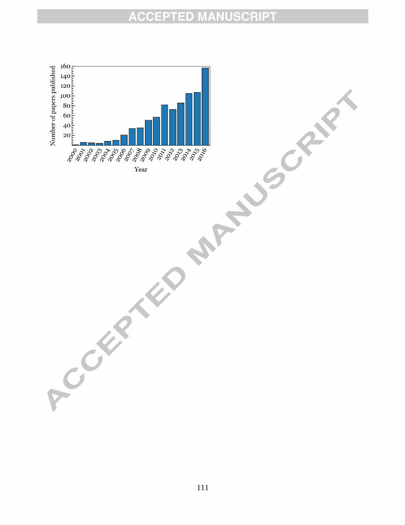
111

112
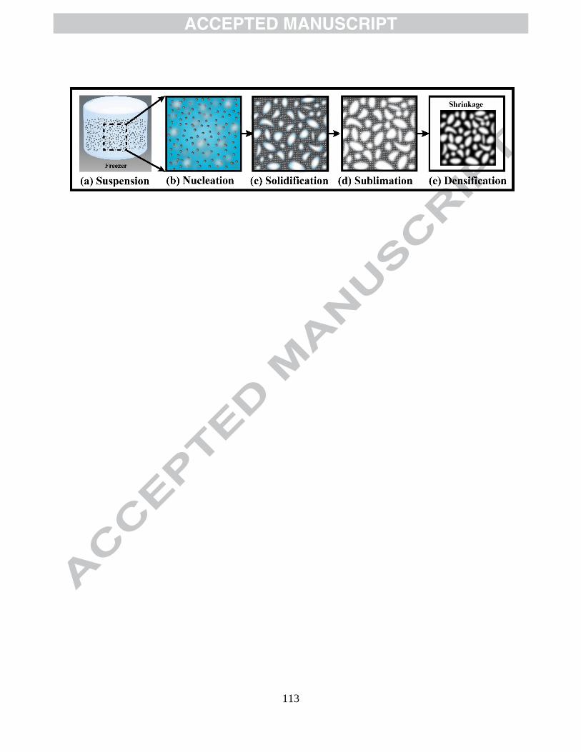
113

114

115

116

117
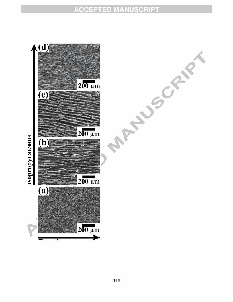
118
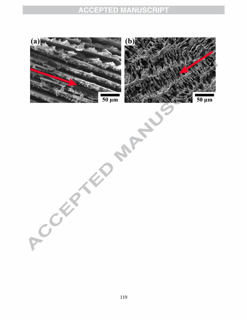
119

120
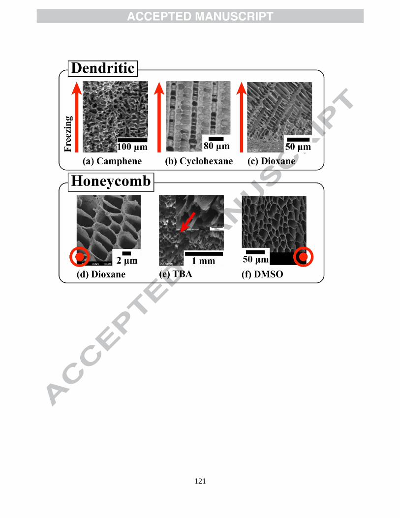
121

122

123

124
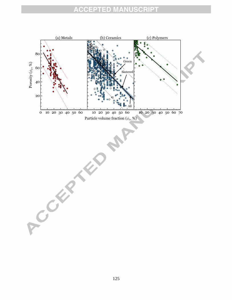
125

126

127

128
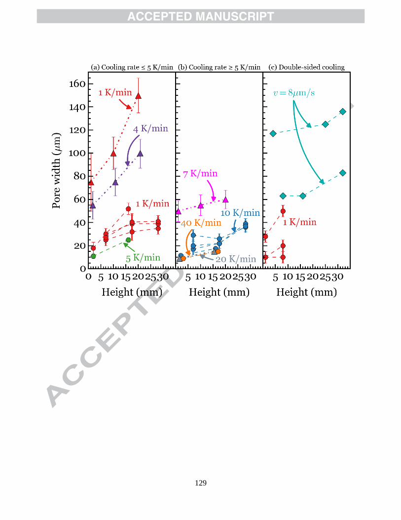
129

130

131

132

133

134

135
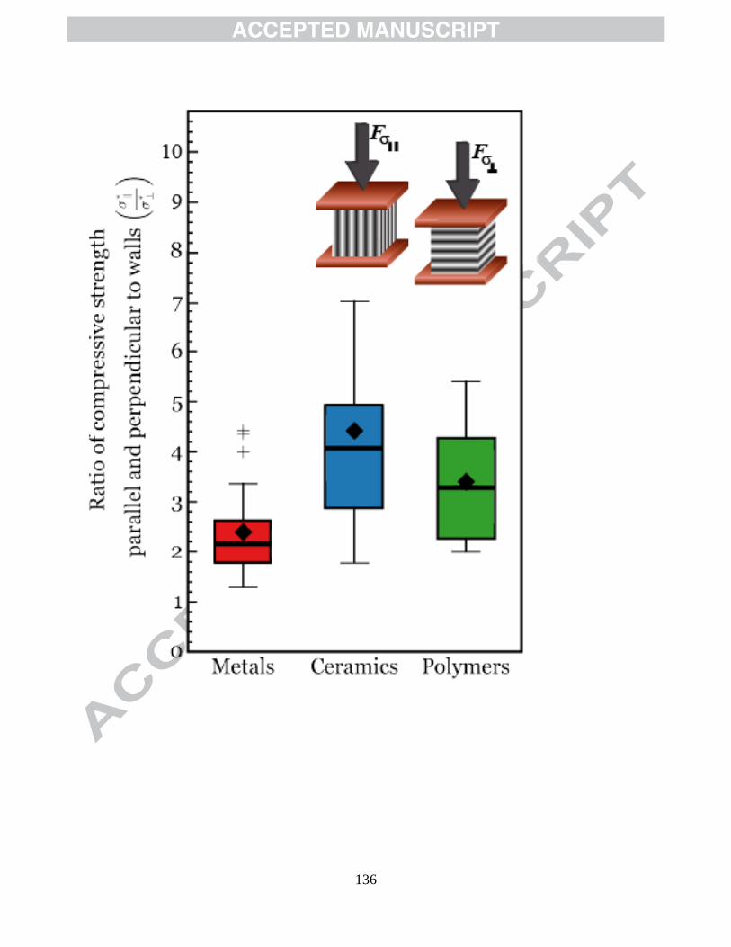
136

137

138

139

140

141

142