Vibrations and fatigue- vibration interactions of laminated composites.
Upload
nguyenlienCategory
view
230download
3
1
FREE VIBRATION STUDY OF ANNULAR
LAMINATED COMPOSITE CIRCULAR PLATES
WITH HOLES
A THESIS SUBMITTED IN PARTIAL FULFILLMENT OF THE REQUIREMENTS FOR
THE DEGREE OF
Bachelor of Technology
In
Civil Engineering
By
Arpita Mohapatra
111CE0608
UNDER THE ABLE GUIDANCE OF
PROF. A.V. ASHA
Department of Civil Engineering, National Institute of
Technology, Rourkela May, 2015
2
CERTIFICATE
This is to certify that the thesis entitled “FREE VIBRATION STUDY OF ANNULAR
LAMINATED COMPOSITE CIRCULAR PLATES WITH HOLES” submitted by
ARPITA MOHAPATRA bearing roll no. 111CE0608 of Civil Engineering Department,
National Institute of Technology Rourkela is a genuine work carried out by her under my
supervision and support.
To the best of my knowledge, the matter embodied in this thesis has not been presented to
any other University / Institute for the award of any Degree or Diploma.
Date: May, 2015
Place: Rourkela
Prof. A.V. Asha DEPARTMENT OF CIVIL ENGINEERING NATIONAL INSTITUTE OF TECHNOLOGY ROURKELA, ODISHA-769008
DEPARTMENT OF CIVIL ENGINEERING
NATIONAL INSTITUTE OF TECHNOLOGY
ROURKELA, ODISHA-769008
3
ACKNOWLEDGEMENT
I am pleased to express my gratitude to my guide Prof.A.V.Asha for her guidance and
constant encouragement and support during the course of my work, her advice and company
not only for the betterment of my research work but also at the time of crisis will be
cherished lifelong. Her patience and enthuse to leave no stones unturned for the completion
of my project has motivated me throughout my project.
I also thank Prof. S. K. Sarangi, Director, NIT Rourkela and Prof. S. K. Sahu, Head of the
Civil Engineering Department, NIT Rourkela, for providing me with the necessary
facilities to carry out my research.
I am thankful to all the professors of the Civil Engineering Department of NIT Rourkela. I
also thank my batch mates who directly or indirectly have helped me a lot to complete my
research work. I also thank all the structural seniors for their valuable advice and intake for
my project.
Finally, my grateful regards to my parents Deba Sundar Mohapatra and Rajashree
Mohapatra who have been constantly supporting and encouraging me at the time of failure
and they are always at my back. They are my constant source of inspiration for these four
years. I want to dedicate this piece of work of mine to my parents.
Thanks to the Almighty for the blessing that he has bestowed upon me in all my endeavours.
ARPITA MOHAPATRA
(111CE0608)
Department of Civil Engineering,
National Institute of Technology, Rourkela
4
ABSTRACT
A composite laminate is layers of fibres of composite materials which are assembled to
provide desired engineering properties. These have a wide range of application, especially in
weight sensitive structures like aircraft and spacecraft. Laminated plates used in these
structures are subjected to dynamic loads. These plates with numerous circular cut outs are
either used to lessen the mass of the whole structure or to expand the inspection. The
presence of cut outs in the plates changes the stress distribution of the plates and makes the
analysis complex. When an external system vibrates and has exactly the same natural
frequency as the internal system, resonance follows producing considerable deflections.
Specific plans can minimise these unnecessary failures. Hence the analysis of the modal
characteristics of these plates is significant.
First an isotropic circular plate’s behaviour is studied and then a circular orthotropic plate has
been considered for this study. The material properties have been fixed. The natural
frequencies have been computed for different boundary condition, hole-radius ratio, and
thickness to radius ratio, and fibre orientation, asymmetric and symmetric holes. The effects
of these variables on the nature of vibration have been analysed and discussed. ANSYS 13.0
is used for the computation of natural frequencies.
5
CONTENTS
CHAPTER NAME PAGE NUMBER
CERTIFICATE……….…………………………………………………..…………………...2
ACKNOWLEDGEMENT………………………………………………….............................3
ABSTRACT…………………………………………………………………...........................4
LIST OF TABLES………………………………………………………….............................7
LIST OF FIGURES……………………………………………………………........................8
CHAPTER 1: INTRODUCTION
1.1 LAMINATED COMPOSITES……………………………………………………….10
1.2 CIRCULAR PLATES WITH HOLES…………………………………......................10
1.3 SIGNIFICANCE OF HOLES………………………………………...........................11
CHAPTER 2: LITERATURE REVIEW
2.1 REVIEW OF LITERATURE…………………………………………........................13
CHAPTER 3: OVERVIEW
3.1 OBJECTIVE OF PRESENT STUDY………………………………………………...16
3.2 SCOPE OF STUDY……………………………………………………......................16
3.2 OUTLINE OF PRESENT WORK …………………………………..……………….17
CHAPTER 4: THEORY AND FORMULATION
4.1 EQUATIONS OF EQUILIBRIUM……………………………………......................19
4.2 STRAIN DISPLACEMENT RELATIONS………………….…...…….................20
4.3 CONSTITUTIVE RELATIONS……………………………...…………………..…..20
4.4 METHODOLOGY………………………………………………………………..…..21
4.5 PROCEDURAL STEPS FOR MODELING IN ANSYS……………………..……...22
CHAPTER 5: RESULTS AND DISCUSSIONS
5.1 INTRODUCTION……………………………………………….………………….29
5.2 VALIDATION WITH PREVIOUS RESULTS……………………….....................29
5.3 RESULTS AND DISCUSSIONS…………………………………………………36

6
5.3.1 LAMINATED ORTHOTROPIC CIRCULAR PLATE……………………...36
5.3.2 LAMINATED COMPOSITE ANNULAR PLATES WITH HOLES…….…40
CHAPTER 6: CONCLUSION
6.1 CONCLUSION……………………………………………...…………....………...44
CHAPTER 7: REFERENCE
7.1 REFERENCE………………………………………………...………...…………...46

7
LIST OF TABLES: TABLE
NUMBER TABLE NAME PAGE
TABLE 5.1 Comparison of natural frequencies in Hz for clamped four-ply circular
laminated plates with lamination scheme [45°/-45°/-45°/45] and diameter=1m
30
TABLE 5.2 Comparison of natural frequencies in Hz for clamped four-ply circular
laminated plates with lamination scheme [0°/-0°/-0°/0°] and diameter=1m 30
TABLE 5.3 Comparison of natural frequencies in Hz for clamped four-ply circular
laminated plates with lamination scheme [45°/-45°/-45°/45 and diameter=2m
30
TABLE 5.4 Comparison of natural frequencies in Hz for clamped four-ply circular
laminated plates with lamination scheme [0°/-0°/-0°/0°] and diameter=2m
31
TABLE 5.5 Comparison of natural frequencies in Hz for clamped four-ply circular
laminated plates with varying thickness
32
TABLE 5.6 Comparison of natural frequencies in Hz for clamped four-ply circular
laminated plates with varying thickness
33
TABLE 5.7 Comparison of natural frequencies in Hz for annular isotropic plate with free-
clamped condition 35
TABLE 5.8 Comparison of natural frequencies in Hz for annular isotropic plate with
varying element length of mesh 35
TABLE 5.9 Natural frequencies in Hz for an annular laminated composite plate with
varying b/a ratio
36
TABLE 5.10 TABLE 5.11: Natural frequencies in Hz for annular laminated composite
plate with varying layer orientation 40
TABLE 5.11 TABLE 5.12: Natural frequencies in Hz for annular laminated composite
plate with different hole locations 41

8
LIST OF FIGURES:
FIGURE
NUMBER FIGURE NAME
PAGE
FIG. 1.1 LAMINATED COMPOSITES 10
FIG. 1.2 CIRCULAR PLATE WITH HOLES 10
FIG. 4.1 SHELL281 ELEMENT 21
FIG 5.1
DEFORMED SHAPES FOR VARYING b/a RATIOS (0.1-
0.8)
37
FIG 5.2
MODELLING (left) AND DEFORMED SHAPE (right) OF
CIRCULAR PLATE WITH ONE CENTRAL HOLE AND
TWO ECCENTRIC SYMMETRIC HOLES
41
FIG 5.3
MODELLING AND DEFORMED SHAPE OF CIRCULAR
PLATE WITH ONE CENTRAL HOLE AND FOUR
ECCENTRIC SYMMETRIC HOLES
42
FIG 5.4
DIMENSIONS OF CIRCULAR PLATE WITH 2 AND 4
SYMMETRIC HOLES AS TAKEN IN TABLE5.11
43

9
Chapter 1
INTRODUCTION

10
1.1 LAMINATED COMPOSITES
Laminated composites are layers of fibres of composite materials that are assembled to
provide desired engineering properties. The individual layers are made up of high modulus,
and high strength fibres in a ceramic matrix, metallic or polymeric material. Lamination is
done to achieve the best properties of the combined layers or a new property in order to make
the material more useful. With the requirement of economical and lightweight structures
composite materials have become popular due to the following reasons:
FIG. 1.1 LAMINATED COMPOSITES
The individual layers are usually orthotropic or transversely isotropic with the laminate then
exhibiting anisotropic, orthotropic, or quasi-isotropic properties [7].
1.2 CIRCULAR PLATES WITH HOLES
Circular plates with holes are widely used in mechanical parts. Circular plates with multiple
circular holes have applications in many engineering structures. They are used either to lessen
the mass of the structure or to upturn the range of inspection or to satisfy engineering
applications. Circular geometries are used in extensive variety of applications because of the
ease of their manufacture [8].
FIG.1.2 CIRCULAR PLATE WITH HOLES
1) They are rigid with high strength to weight
ratio
2) Good Electrical resistance,
3) Resistance to chemicals and weather
4) Good directional properties
11
1.3 SIGNIFICANCE OF HOLES
A composite structure sometimes may be provided with various types of holes for assembling
the parts or units in the structure, for passage of the cables and controlling mechanisms, for
inspection, maintenance and attachment to other units [8]. These holes in the structure usually
lead to the variation of natural frequency and also in the decrease of the respective potential.
If the hole is eccentric, the natural frequency of structures is expected to differ considerably
from that of a plate with central holes [8].

12
Chapter 2
REVIEW OF LITERATURE

13
2.1 REVIEW OF LITERATURE
Lin (1982) presented an analytical method for calculating the free transverse vibrations of
uniform circular plates and membranes with eccentric holes. The wave equations governing
the small transverse motion of the plates and membranes were solved to satisfy the boundary
conditions at both inner and outer edges, and the associated frequency equations for the plates
and membranes were derived. The analysis included the vibrations of uniform circular plates
and membranes with concentric holes as special cases.
Srinivasamurthy et al. (1987) presented a non-linear shear deformable model to study the
dynamic behaviour of circular plates composed of orthotropic layers. The basic equations
were originated by Hamilton's principle and expression of the changing calculus in terms of
the transverse displacement that yielded a non-linear ordinary differential equation for the
time function. This was then resolved by using the methods of harmonic balance.
Bicos et al. (1989) used a finite element method to calculate the natural frequencies, mode
shapes, and damping factors of rectangular plates, cylinders, and cylindrical panels with free,
clamped, or simply supported edges, and with or without circular cut outs.
Chai Gin Boay (1996) used finite element method to compare results with experimental data
on the free vibration of symmetric laminated composite plates containing a central hole. The
effect of parameters such as the hole sizes, the boundary conditions along the edges of the
plate and the aspect ratio of the plate on frequencies were studied. The stacking sequence and
lamination materials were not changed. There was close correlation between numerical
studies and experimental data.
Lee (2007) used semi analytical methodologies to solve vibrational characteristics and mode
shapes for circular plates with various circular holes .The direct searching methodology was
adopted to establish the vibrational characteristics through SVD. For the cases of circular
plates with various eccentric and centric circular cut outs, the results were also matched with
those of FEM using ABAQUS.
Cheng et al. (2009) studied the effects of the boundary conditions, eccentric holes, and size
of the cut outs on vibration modes using FEM analysis code NASTRAN and examined it
through both universal and local analysis.
14
Malekzadeh et al. (2010) operated a 3 dimensional layer wise FEM in the direction of the
thickness to study the natural frequencies of a thick laminated circular annular plate
supported on a flexible foundation.
Hosseini-Hashemi et al. (2012) presented the natural frequency of laminated transversely
isotropic circular plates. The plate had an axisymmetric rigid core attached at the centre. The
governing equation of motion was obtained using Mindlin's first order shear deformation
(FSDT) plate theory.
Pushparaj (2012) used the ANSYS software for analysing the plates with various boundary
conditions and different orientation of laminates. Eight-noded Shell99 was used throughout
the analysis. Two different boundary conditions were considered - CFFF-(clamped free free
free) and CFCF-(clamped free clamped free) conditions.
Thakare (2013) determined experimentally the natural frequencies of a plate with various
holes and compared the results obtained from ANSYS. The relationship among parameter
variations and frequencies was analysed.
Hussain et al. (2014) investigated the natural frequency of four layered angle ply
symmetrically laminated plates with various lamination angles of laminas with different hole
locations. The ANSYS 13.0software was used for modelling and analysis of the laminated
plates under clamped boundary conditions. The eight noded shell 99 was used throughout the
analysis. Length to height ratio considered is 40 and 200. The ratio of hole area to the plate
area was maintained constant throughout the analysis as 0.05. From the analysis it was
inferred that the fundamental frequency of laminated composite plates decreases with
increase in L/h ratio.
Rahimi et al. (2014) presented a three-dimensional elasticity theory by means of a state-
space centred differential quadrature technique for natural frequency investigation of fibre
metal laminate plate with cut outs. A semi analytical approach which uses state-space in the
thickness and differential quadrature in the radial direction was implemented for evaluating
the vibration characteristics and frequencies of the annular circular plates.

15
Chapter 3
OVERVIEW
16
3.1 OBJECTIVE OF PRESENT STUDY
‘‘the free vibrations of circular plates have been of practical and academic interest for at
least a century and a half’’ [11]
Resonance can occur when an external system’s natural frequency matches with the internal
system, causing considerable deflection and sudden collapse in inappropriate constructions.
Precise designs have potential to minimise these unnecessary vibrations. Although many
results of vibration analysis for solid or annular plates are already presented in the literature
work and the analysis of these circular plates have been done by various methods like
differential quadrature method, finite element analysis, SVD, ABAQUS, ANSYS,
Chebyshev–Ritz method, moving Least Square Method and several other semi analytical
methods, few studies have been done on the problem of laminated circular plate with holes
and I believe it to be a newly considered study that could be used as a means of comparison
of frequencies with those of solid circular plates. Plates with holes are frequently used in
various structures. This would also enhance my knowledge on the topic.
3.2 SCOPE OF STUDY
Laminated composites are materials made by bonding layers to bring out the superior and
desirable qualities of the individual materials. Due to its qualities like light weight and high
strength it has been applied in various engineering applications. Hence after a thorough
review of literature, it was decided to study the free vibration of orthotropic laminated
composite plates with circular holes that can be centric, eccentric, symmetric and asymmetric
for various changes in parameters like aspect ratio, fibre orientation, number of layers,
thickness to radius ratio, etc. The present study deals with the natural frequency of
orthotropic laminated composite plates having single cut-out as well as various eccentric,
symmetric and asymmetric cut outs. The stress distribution is complicated in such type of
structures. It can fail due to resonance occurring due to vibration. Hence this study is
important to know the behaviour of such type of plates.

17
3.2 OUTLINE OF PRESENT WORK
An attempt has been made to study the vibration characteristics of circular laminated
orthotropic composite plates with holes. For generalisation of the analysis, first an isotropic
plate with a hole is assumed with inner radial edge clamped and outer radial edge free and
analysis is done by varying the outer to inner radius ratio and the element thickness for mesh
size. The effect of boundary conditions, hole-size, and lamination scheme and fibre
orientation on natural frequencies of vibration is studied, and based on these results; the
analysis of an annular orthotropic plate for various boundary conditions is carried out.
First, a single circular hole at the centre is considered and then the analysis is further
extended to holes that are eccentric. All the calculations have been done with the finite
element package ANSYS 13.0.
This thesis comprises of seven chapters. The first chapter introduces the importance of the
laminated composite plates in various fields, explains the complexity of circular plates with
holes and significance of holes in a structure.
In the second chapter, the literature review is presented. All the research papers relevant to
this study were reviewed in detail and have been discussed briefly
The third chapter states the objective and scope of the study based on the detailed literature
review.
The fourth chapter presents the theoretical formulation. All the computation was carried out
using ANSYS. The details of modelling in ANSYS are also presented.
In chapter 5, the results obtained in the present investigation are tabulated. The effects of
various parameters like plate thickness, boundary conditions, number of layers, size of hole,
aspect ratio, fibre orientation and hole shape is discussed.
Chapter 6 states all the conclusions that are inferred from the results obtained.
Chapter 7 gives all sources of the research papers using which studies were carried out.

18
Chapter 4
THEORY AND FORMULATION

19
4.1 EQUATIONS OF EQUILIBRIUM
The equations of motion for the free vibration of a symmetric cross-ply laminated circular
plate can be expressed as [6]
) +
) =Io
(
)
(
)+
+
(
)=
Where, Io and I2 are the mass inertia tensor components defined as,
ρ and h denote the density and total thickness.
As per the First order Shear Deformation Theory (FSDT) [11], after deformation the
transverse normals to the mid surface do not remain perpendicular to the mid surface due to
the effects of transverse shear strains. The displacement field at time t is given by
U(x, y, z, t) = u0(x, y, t) + zφx(x, y, t),
V(x, y, z, t) = v0(x, y, t) + zφy (x, y, t),
W(x, y, z, t) = w0(x, y, t),
Where (u0, v0, w0) are the displacements of a point on the plane z = 0, and φx and φy are,
respectively, the rotations of a transverse normal about the y and x axes.

20
4.2 STRAIN DISPLACEMENT RELATIONS
Strain displacement relationships in cylindrical co-ordinates [11],
{
}
=
{
}
+ z
{
}
Where uo, vo, wo are mid-plane displacements in the r, and ϕr, are
rotations of the transverse normal about r and axes.
4.3 CONSTITUTIVE RELATIONS
The relationship of the force and moment resultants to the mid-plane strains and curvatures
has been expressed by the laminate constitutive equations. The force resultants and moment
resultants are given by
{
}=[
]
{
}
+[
]
{
}
{
}=[[
]]
{
}
+[
]
{
}
∑
( -
∑
∑
Where Aij denotes the extensional stiffnesses, Dij denotes the bending stiffnesses, and Bij
denotes the bending–extensional coupling stiffnesses of a laminate.
21
4.4 METHODOLOGY
ANSYS 13.0 version is used for modelling and vibrational analysis of circular plates with
holes. ANSYS Mechanical software is a finite element method software for structural
analysis, including linear, nonlinear and dynamic studies.
The element used for modelling the circular plate is the SHELL 281 element.
SHELL281 is suitable for analysing structures. The element has eight nodes with six degrees
of freedom at each node: translations in the x, y, and z axes, and rotations about the x, y, and
z-axes. SHELL281 is well-suited for linear, large rotation, and large strain nonlinear
applications. Change in shell thickness is accounted for in nonlinear analyses. For layered
applications for modelling composite shells or sandwich construction, SHELL281 is applied
for the modelling of an accurate composite shell. This is governed by the FSDT theory
(Mindlin-Reissner shell theory). Logarithmic strain and true stress measures is the base for
element formulation. Finite membrane strains (stretching) are allowed by the element
kinematics. However, the curvature variations are assumed to be insignificant. The shell
section information and eight nodes (I, J, K, L, M, N, O and P) defines the element [1].
FIG 4.1 SHELL281 ELEMENT

22
4.5 PROCEDURAL STEPS FOR MODELING IN ANSYS
1. Preferences → Structural → Ok
2. Pre-processor → Element type → Add → Structural Mass → Shell → 8node 281→ Ok
3. Pre-processor → Material Properties → Material Models → Structural → linear →
Elastic →Orthotropic →Density →Enter the density of composite laminate →Ok

23
4. Preprocessor → Modelling → Create → Areas → solid circle → Sections → Shell
→Lay-up→Add/Edit→Ok

24
5. Preprocessor → Meshing → Mesh Tool → Size Controls → Enter length of element →
Ok
MESHING USING SMART SIZE
MESH 6 →MESH 5 →MESH 4 →MESH 3 → MESH 2 →MESH 1

25

26
6. Preprocessor → Loads → Define Loads → Apply → Structural → Displacement
7. Preprocessor → Loads → Analysis Type →New Analysis → Type of analysis –
Modal → Ok → Analysis Options →Mode extraction method – Block Lanczos →
No. of modes to extract - 8→Enter the start and end frequency → Ok

27
8. Solution → Solve → Current LS
9. For viewing the results, follow the step given below: General Post processing →Results
Summary

28
Chapter 5
RESULTS AND DISCUSSIONS

29
5.1 INTRODUCTION
A laminated composite circular plate with a central hole (annular plate) is studied for its
dynamic characteristics. First the validity of the ANSYS formulation is checked for its
accurateness for a solid plate by comparing the results obtained with that presented by Cong
et al [6]. Then the dynamic characteristics for an annular laminated composite plate are
studied.
5.2 VALIDATION WITH PREVIOUS RESULTS
A plate with the following parameters as proposed by Cong et al. [6] was considered for the
analysis. The non-dimensional natural frequency is expressed as,
√
BOUNDARY CONDITIONS:
Clamped Edge
No displacements or rotations
PARAMETERS INVOLVED:
Density, ρ = 1580kg/m 3
Diameter, b = 1 OR 2 m
Thickness, h or t = 0.1b
The Young’s moduli, E1 =40 GPA and E2=1GPa
Shear moduli, G23= 0.5 GPA, G13= 0.6GPa, and G12= 0.5GPa
30
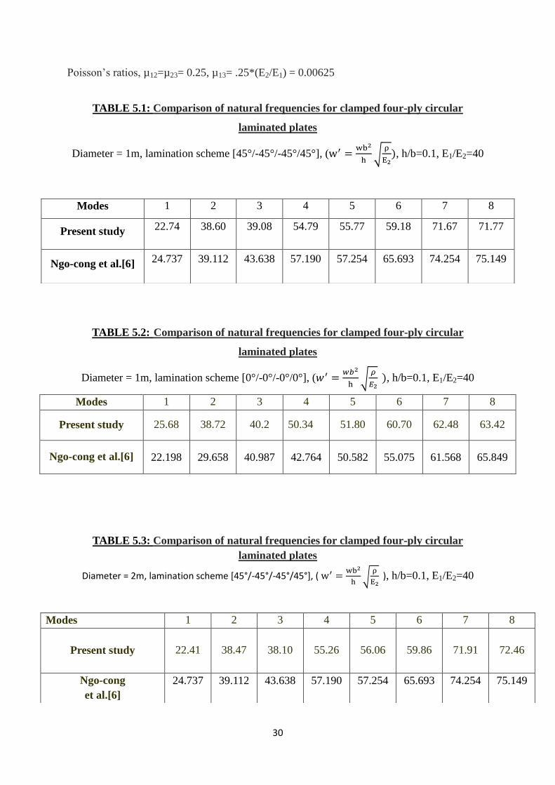
Poisson’s ratios, µ12=µ23= 0.25, µ13= .25*(E2/E1) = 0.00625
TABLE 5.1: Comparison of natural frequencies for clamped four-ply circular
laminated plates
Diameter = 1m, lamination scheme [45°/-45°/-45°/45°], (w
√
, h/b=0.1, E1/E2=40
TABLE 5.2: Comparison of natural frequencies for clamped four-ply circular
laminated plates
Diameter = 1m, lamination scheme [0°/-0°/-0°/0°], (𝑤
√
, h/b=0.1, E1/E2=40
TABLE 5.3: Comparison of natural frequencies for clamped four-ply circular
laminated plates
Diameter = 2m, lamination scheme [45°/-45°/-45°/45°], ( w
√
), h/b=0.1, E1/E2=40
Modes 1 2 3 4 5 6 7 8
Present study 22.74 38.60 39.08 54.79 55.77 59.18 71.67 71.77
Ngo-cong et al.[6] 24.737 39.112 43.638 57.190 57.254 65.693 74.254 75.149
Modes 1 2 3 4 5 6 7 8
Present study 25.68 38.72 40.2 50.34 51.80 60.70 62.48 63.42
Ngo-cong et al.[6] 22.198 29.658 40.987 42.764 50.582 55.075 61.568 65.849
Modes 1 2 3 4 5 6 7 8
Present study 22.41 38.47 38.10 55.26 56.06 59.86 71.91
72.46
Ngo-cong
et al.[6]
24.737 39.112 43.638 57.190 57.254 65.693 74.254 75.149

31
TABLE 5.4: Comparison of natural frequencies for clamped four-ply circular
laminated plates
Diameter = 2m, lamination scheme [0°/-0°/-0°/0°], (w
√
, h/b=0.1, E1/E2=40
Modes 1 2 3 4 5 6 7 8
Present study 25.78 38.66 39.96 51.03 51.88 59.52 63.66 64.02
Ngo-cong
et al. [6] 22.198 29.658 40.987 42.764 50.582 55.075 61.568 65.849
It is seen from Tables 5.1 to 5.4 that the results of the present formulation are quite similar to
that of Cong et al [6]. Some variations may be observed due to the assumption of the density.
We can observe that as the diameter is increased from 1m to 2 m, the frequency increases for
both the orientation of the fibres.
In the next study, the natural frequency of a solid orthotropic plate is analyzed by varying the
thickness to radius ratio from 0.001 to 0.2.

32
TABLE 5.5: Comparison of natural frequencies for clamped four-ply circular
laminated plates with varying thickness:
Diameter =1m, [45°/-45°/-45°/45°], (w
√
, E1/E2=40
t/b ratio Modes 1 2 3 4 5 6 7 8
0.001
Present study 43.9 86.95 89.78 137.46 146.1 153.35 202.87 207.14
Ngo-cong
et al.[6] 46.435 70.615 110.019 115.873 143.115 163.166 184.000 218.970
0.050
Present study 31.63 57.48 58.63 85.162 87.97 92.00 116.35 116.98
Ngo-cong
et al.[6] 35.506 55.366 70.743 84.208 89.932 112.326 117.096 117.614
0.1
Present study 22.74 38.60 39.08 54.79 55.77 59.18 71.67 71.77
Ngo-cong
et al. [6]
24.737 39.112 43.638 57.190 57.254 65.693 74.254 75.149
0.15
Present study 17.36 28.53 28.75 754.1 39.7 43.26 50.82 50.9
Ngo-cong
et al. [6] 18.580 29.222 31.328 41.286 41.855 46.084 53.062 53.211
0.2
Present study 13.9 22.24 22.58 30.88 31.14 33.72 39.17 39.25
Ngo-cong
et al.[6] 14.754 23.093 24.359 32.151 32.686 35.454 41.023 41.079
With an increase in the t/b ratio, natural frequency decreases significantly. The results are also
quite comparable. In Table 5.6, the results are presented for another lamination scheme.

33
TABLE 5.6: Comparison of natural frequencies in Hz for clamped four-ply circular
laminated plates with varying thickness
Diameter =1m, [0°/-0°/-0°/0°], (
√
, E1/E2=40
As can be observed, the results match quite well. With the increase in the thickness to
radius ratio, the natural frequency decreases significantly for various modes.
t/b ratio Modes 1 2 3 4 5 6 7 8
0.001
Present study 48.41 96.67 105.83 139.16 150.21 183.07 188.28 195.4
Ngo-cong
et al.[6] 45.245
56.510
72.646 93.440 118.647 119.399 134.972 146.804
0.050
Present study 32.73 57.76 62.03 77.84 82.28 97.91 98.59 101.56
Ngo-cong
et al. [6] 33.401 42.190 55.649 70.957
73.602
80.909 94.742 95.602
0.1
Present study 25.68 38.72 40.2 50.34 51.80 60.70 62.48 63.42
Ngo-cong
et al. [6] 22.198 29.658 40.987 42.764 50.582 55.075 61.568 65.849
0.15
Present study 18.68 28.42 29.15 36.83 37.7 43.89 44.64 46.08
Ngo-cong
et al. [6] 16.424 23.040 30.528 32.359 37.045 43.081 45.728 45.907
0.2
Present study 14.93 22.7 22.82 29.16 29.71 33.55 34.388 36.67
Ngo-cong
et al. [6] 13.111 18.923 23.801 26.641 29.339 35.1..09 35.246 36.465
34
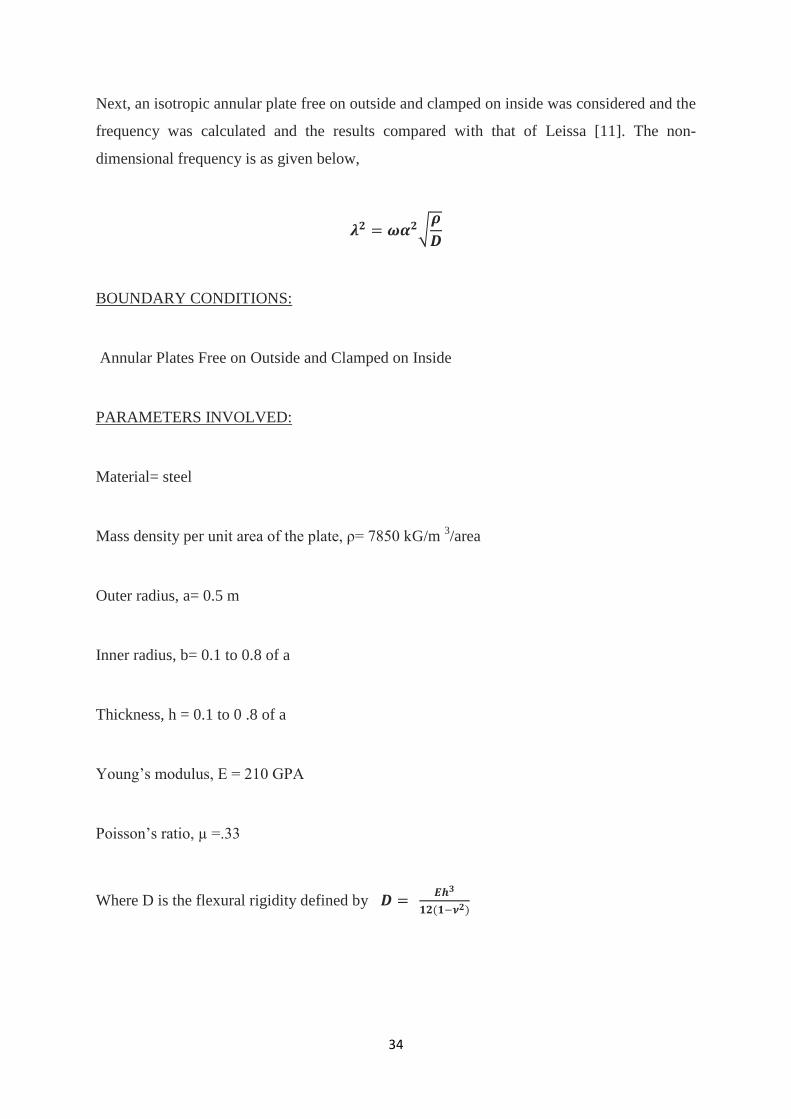
Next, an isotropic annular plate free on outside and clamped on inside was considered and the
frequency was calculated and the results compared with that of Leissa [11]. The non-
dimensional frequency is as given below,
√
BOUNDARY CONDITIONS:
Annular Plates Free on Outside and Clamped on Inside
PARAMETERS INVOLVED:
Material= steel
Mass density per unit area of the plate, ρ= 7850 kG/m 3/area
Outer radius, a= 0.5 m
Inner radius, b= 0.1 to 0.8 of a
Thickness, h = 0.1 to 0 .8 of a
Young’s modulus, E = 210 GPA
Poisson’s ratio, µ =.33
Where D is the flexural rigidity defined by

35
TABLE 5.7: Comparison of natural frequencies for annular isotropic plate with free-
clamped condition:
Diameter=1m, λ ωα √
& h = 0.05m
b/a
ratio 0.1 0.2 0.3 0.4 0.5 0.6 0.7 0.8
Present study 1.6 1.91 2.24 2.64 3.16 3.94 5.19 7.51
Leissa[11] 2.04 2.25 2.52 2.53 3.35 4.044 5.08 6.96
As b/a ratio increases, frequency of the plate increases. This happens due to the increase in
radial stiffness. It can be observed that the results are quite agreeable. The discrepancies may
be due to the fact that the thickness was not defined and hence was assumed in the present
formulation.
TABLE 5.8: Comparison of natural frequencies in Hz for annular isotropic plate with
varying element length of mesh
Diameter=1m, [45°/-45°/-45°/45°], b/a=0.4, t/a=0.2
From Table 5.8, it is seen that there is a large variation in results as the mesh element length
is increased; hence this method of meshing is not adopted. Automatic meshing was done in
ANSYS using smart meshing tool.
Modes 1 2 3 4 5 6 7 8
Element length
.2 282.49 500.77 506.85 721.88 729.19 784.06 936.19 942.17
.15 281.9 502.18 514.2 710.09 729.72 773.31 919.35 937.2
.1 287.61 494.91 499.89 702.55 712.84 759.83 912 921.61
.05 282.16 491.82 498.14 711.02 713.98 762.63 915.56 923.13
.01 277.14 493.31 495.83 702.12 705.45 748.37 910.57 912.43

36
5.3 RESULTS AND DISCUSSIONS
5.3.1 LAMINATED ORTHOTROPIC CIRCULAR PLATE
Natural frequencies for annular four-ply circular laminated plates with clamped free
conditions are analyzed using ANSYS software.
TABLE 5.9: Natural frequencies in Hz for an annular laminated composite plate with
varying b/a ratio
Diameter =1m, [45°/-45°/-45°/45°], ν . 5 E1/E2=40, t/a=0.2
Modes 1 2 3 4 5 6 7 8
b/a ratio
0.1 133.35 148.88 164.28 177.5 260.2 296.58 435.33 492.5
0.2 190.74 192.87 206.4 279.9 296.1 337.6 485.84 495.75
0.3 242.53 244.58 255.08 303.26 315.88 488.22 499.82 501.41
0.4 314.9 319.9 322.6 365.17 382.9 518.12 524.17 700.78
0.5 408.9 411.1 419.48 446.57 468.74 556.87 591.9 740.24
0.6 542.7 557.02 557.6 604.2 610.5 697.54 699.33 817.7
0.7 770.6 780.98 786.9 825.34 825.8 894.15 896.33 989.13
0.8 1210.4 1221.3 1224.1 1254 1256 1306.4 1308.7 1377.6

37
Keeping the outer radius of a circular plate constant if we increase the inner radius, the length
of the composite circular plate along the radii decreases and there is an increase in the plate’s
stiffness. Hence the frequency of the system increases [2].
FIG 5.1 DEFORMED SHAPES FOR VARYING b/a RATIOS (0.1-0.8)
b/a=0.1
b/a=0.2
b/a=0.3

38
b/a=0.4
b/a=0.5
b/a=0.6

39
b/a=0.7
b/a=0.8

40
TABLE 5.10: Natural frequencies in Hz for annular laminated composite plate with
varying layer orientation
Diameter (a) =1m, t/a =0.2 E1/E2=40, b/a=0.4
The natural frequencies of the annular plate was studied for varying layer orientations. This is
shown in Table 5.10. The results for [0°/-0°/-0°/0°] show the lowest frequencies and for
[45°/-45°/-45°/45°] show the highest frequencies.
Modes
1 2 3 4 5 6 7 8
Layers
[0°/-0°/-0°/0°] 64.74 141.4 158.7 167.9 223 240 334.84 360.4
[0°/90°/0°] 74.73 139.6 159.3 165.72 235.1 258.4 409.66 422.9
[0°/90°/90°/0°] 76.6 143.23 165.61 169.8 256.8 286.3 448.92 466.68
[45°/-45°/-45°/45°] 133.35 148.88 164.28 177.5 260.2 296.58 435.33 492.5

41
5.3.2 LAMINATED COMPOSITE ANNULAR PLATES WITH HOLES
The natural frequency of an orthotropic laminated circular plate was analysed with inner edge
of central hole clamped and various symmetric holes.
TABLE 5.11: Natural frequencies in Hz for annular laminated composite plate with
different hole locations
Diameter (a) =1m, ν . 5 E1/E2=40, [45°/-45°/-45°/45°], t/a=0.4
MODES 1 2 3 4 5 6 7 8
TYPES OF HOLES
ONE CENTRAL HOLE 314.9 319.9 322.6 365.17 382.9 518.12 524.17 700.78
ONE CENTRAL HOLE+ TWO
SYMMETRIC HOLES 237.67 242.86 248.93 251.06 266.77 346.19 367.97 503.00
ONE CENTRAL HOLE +FOUR
SYMMETRIC HOLES 229.32 235.96 240.70 244.73 272.94 334.25 369.44 495.13
With increase in number of symmetric holes the natural frequency decreases.
FIG 5.2 MODELLING (left) AND DEFORMED SHAPE (right) OF CIRCULAR
PLATE WITH ONE CENTRAL HOLE AND TWO ECCENTRIC SYMMETRIC
HOLES

42
FIG 5.3 MODELLING AND DEFORMED SHAPE OF CIRCULAR PLATE WITH
ONE CENTRAL HOLE AND FOUR ECCENTRIC SYMMETRIC HOLES

43
FIG 5.4 DIMENSIONS OF CIRCULAR
PLATE WITH 2 AND 4 SYMMETRIC
HOLES AS TAKEN IN TABLE 5.11
0.35m
0.5m
0.05m
0.05m
0.5m
0.35m
0.2m
0.2m

44
CHAPTER 6
CONCLUSIONS

45
6.1 CONCLUSION
1. In case of solid clamped four-ply circular laminated plate, the results are quite similar to
the research paper [6]. Some variations may be observed due to the assumption of the
density. As the diameter of hole increases, the natural frequency increases.
2. From the results we conclude that for a solid plate as radius increases, mass and stiffness
increases and hence the natural frequency of the system being directly proportional to the
stiffness increases.
3. The natural frequency decreases significantly with increase in the thickness to radius ratio.
4. There is an increase in the natural frequency of the plate as the inner radius to outer radius
ratio increases. This happens because of the increase in radial stiffness of the system.
5. The discrepancies in case of an annular isotropic plate with free-clamped condition may be
due to the fact that the thickness was not defined and hence was assumed in the present
formulation.
6. There is a large variation in results when the mesh element length method is considered for
meshing; hence this method of meshing is not suitable to obtain accurate results.
7. Keeping the outer radius of a circular plate constant if we increase the inner radius, the
length of the composite circular plate along the radius decreases and there is an increase in
the plate’s radial stiffness. Hence the frequency of the system increases [2].
8. It is seen that as thickness increases, the natural frequency of the plate increases.
9. With increase in number of symmetric holes the natural frequency decreases. The mass of
the system decreases, stiffness decreases and hence natural frequency decreases.

46
CHAPTER 7
REFERENCES

47
7.1 REFERENCES
[1] ANSYS Technical Manual
[2] Baltaci Aysun, Sarikanat Mehmet and Yildiz Hasan, “Buckling Analysis of Laminated
Composite Circular Plates with Holes”, Journal of reinforced plastic and composites, DOI:
10.1177/0731684406062065, (2006).
[3] Bicos, A.S., and Springer G.S., “Vibrational characteristics of composite panels with
cut-outs", AIAA Jnl., Vol.27, pp.1116-1122, (1989).
[4] Boay Chai Gin, “Free vibration of laminated composite plates with a central circular
hole”, Composite Structures, (Impact Factor: 3.12). 08/1996; 35(4):357-368.
DOI: 10.1016/S0263-8223(96)00037-2, (1996).
[5] Cheng Gang, Wang Wiedong, Cheng Quan, “Free Vibration of Circular Plate with
Oscillators and Elastic Supports at Arbitrary Positions by Integral Equation Method”, WRI
World Congress on Computer Science and Information Engineering, Conference: CSIE, Los
Angeles, California, USA, 7 Volumes, (2009).
[6] Cong D. Ngo, N. Mai-Duy, W. Karunasena, T. Tran-Cong, “Free Vibration Analysis
of Laminated Composite Plates based on FSDT using One-Dimensional IRBFN Method”,
Computers and Structures , (2010).
[7] http://en.wikipedia.org/wiki/Composite_laminates
[8] Hosseini Hashemi Shahrokh, Arsanjani M, “Exact characteristic equations for some of
classical boundary conditions of vibrating moderately thick rectangular plates”,
International journal of solids and structures, Volume 42,Issue, 3, Pages 819-853, Publisher
Pergamon, (2012).
48
[9] Hussain Syed Altaf , Pandurangadu V. , Kumar K. Palani, “Vibration Analysis of
Laminated Composite Plates with Holes”, International Journal of Engineering Sciences &
Research Technology, ISSN: 2277-9655 Scientific Journal Impact Factor: 3.449 (ISRA),
Impact Factor: 1.852, (2014).
[10] Lee Wie Ming, “Free vibration analysis of circular plates with multiple circular holes
using indirect BIEMs”, Journal of Sound and Vibration , (Impact Factor: 1.86). 07/2007;
304(3-5):811-830. DOI: 10.1016/j.jsv.2007.03.026), (2007).
[11] Leissa Arthur W., “Vibration of Plates”, (1969).
[12] Leissa, A. W., Baharlou, B, “Vibration and buckling of generally laminated composite
plates with arbitrary edge conditions”, Journal of Mechanical Sciences, Vol.29, pp. 545-555,
(1993).
[13] Leissa, A.W., So. J., “Three-dimensional vibrations of thick circular and annular
plates,” Journal of Sound and Vibration, Vol.209, pp.15-41, (1998).
[14] Lin Chen Shan, “Chien’s Solution and Its Asymptotic Behaviour in Large Deflection of
Circular Plates”, Applied Mathematics and Mechanics, Vol. 3, Issue (4): 557-562, (1982).
[15] Malekzadeh P., Afsari A. , Zahedinejad P. , Bahadori R. , “Three-dimensional layer
wise-finite element free vibration analysis of thick laminated annular plates on elastic
foundation”, Applied Mathematical Modelling, Volume 34, Issue 3, March 2010, Page776–
790, (2010).
[16] PushpaRaj Santhosh D., “Dynamic Analysis of Laminated Composite Plates with
Holes”, MTech thesis, NIT ROURKELA, Engineering and Technology > Civil
Engineering > Structural Engineering, http://ethesis.nitrkl.ac.in/3920/, (2012).

49
[17] Rahimi G. H., Gazor M. S., Hemmatnezhad M., Toorani H. , “Free Vibration
Analysis of Fibre Metal Laminate Annular Plate by State-Space Based Differential
Quadrature Method”, Advances in Materials Science and Engineering, Volume 2014 (2014),
Article ID 602708, 11 pages, (2014).
[18] Srinivasamurthy K., Chia C. Y., “Nonlinear Vibration and Bending of Laminated
Anisotropic Circular Plates”, Composite Structures 4, pp. 436-446, (1987).
[19] Thakare S. B., “Free Vibration Analysis of circular plates with holes and cutouts”
IOSR 2013. E-ISSN: 2278-1684, p-ISSN: 2320-334X, PP 46-54, Volume 8, Issue 2(Jul. -
Aug. 2013), (Impact factor: 1.485), (2013).