FREE SPACE OPTICS SYSTEM: PERFORMANCE AND LINK · PDF fileFREE SPACE OPTICS SYSTEM:...
24
http://www.ijccr.com VOLUME 1 ISSUE 3 MANUSCRIPT 4 NOVEMBER 2011 FREE SPACE OPTICS SYSTEM: PERFORMANCE AND LINK AVAILABILITY Gaurav Soni Assistant Professor, Department of Electronics and Communication Engineering, Amritsar College of Engineering and Technology, Amritsar, India Jagjeet Malhotra Associate Professor, Department of Electronics and Communication Engineering, DAV College of Engineering and Technology, Jalandhar, India ABSTRACT Free Space Optics (FSO) is a telecommunications technology that transmits data in the form of optical signals across the air and, as such, can be considered as a wireless (line-of-sight) transmission system; this technology is capable of handling data rates at the Gbps level, does not require licensing, and can be deployed at one-fifth of the cost of fiber; also, the narrow beams employed in the transmission of signals are very difficult to be affected by jamming, interception or interference. This article reviews the FSO Link design and addresses the atmospheric challenges faced by FSO Technology. In the end we studied the FSO Link availability dependence on link distance and atmospherics conditions.
Transcript of FREE SPACE OPTICS SYSTEM: PERFORMANCE AND LINK · PDF fileFREE SPACE OPTICS SYSTEM:...

http://www.ijccr.com
VOLUME 1 ISSUE 3 MANUSCRIPT 4 NOVEMBER 2011
FREE SPACE OPTICS SYSTEM: PERFORMANCE AND LINK
AVAILABILITY
Gaurav Soni
Assistant Professor, Department of Electronics and Communication Engineering,
Amritsar College of Engineering and Technology, Amritsar, India
Jagjeet Malhotra
Associate Professor, Department of Electronics and Communication Engineering,
DAV College of Engineering and Technology, Jalandhar, India
ABSTRACT
Free Space Optics (FSO) is a telecommunications technology that transmits data in the form of
optical signals across the air and, as such, can be considered as a wireless (line-of-sight)
transmission system; this technology is capable of handling data rates at the Gbps level, does
not require licensing, and can be deployed at one-fifth of the cost of fiber; also, the narrow
beams employed in the transmission of signals are very difficult to be affected by jamming,
interception or interference. This article reviews the FSO Link design and addresses the
atmospheric challenges faced by FSO Technology. In the end we studied the FSO Link
availability dependence on link distance and atmospherics conditions.

http://www.ijccr.com
VOLUME 1 ISSUE 3 MANUSCRIPT 4 NOVEMBER 2011
Keywords: FSO, LEDs, scintillation, Scattering Turbulence, Visibility
INTRODUCTION
Free-Space Optical (FSO) communication is reputed for its ability to proffer solution to the
access network bottle-neck but when used over long range communication links, it suffers from
scintillation caused by the atmospheric turbulence. Free Space Optics (FSO) is a promising
optical technology that has a great chance to compliment the traditional wireless
communications, through provision of high bandwidth, excellent security and reaching places
where cable technology could never reach. Quality of FSO links however is greatly affected by
weather conditions and link distance. Free Space Optics (FSO) is a very fast and reliable
endorsement to radio links using light to transmit data. There is a certain amount of disconnect
between the perception and reality of Free Space Optics (FSO) [1], both in the marketplace and
in the technical community. In the marketplace, the requirement for FSO technology has not
grown to even a fraction of the levels predicted a few years ago. In the technical community,
proposed solutions for the limitations of FSO continue to miss the mark. The main commercial
limitation for FSO is that light does not propagate very far in dense fog, which occurs a non-
negligible amount of the time. There is no known solution for this problem (other than using
microwave or other modality backup systems), and therefore FSO equipment has to be priced
very competitively to sell in a marketplace dominated by copper wire, fiber optic cabling and
increasingly lower cost and higher bandwidth wireless microwave equipment. Expensive
technologies such as adaptive optics, which could potentially increase equipment range in clear
weather, do not justify the added cost when expected bad weather conditions are taken into
account.

http://www.ijccr.com
VOLUME 1 ISSUE 3 MANUSCRIPT 4 NOVEMBER 2011
FSO BLOCK DIAGRAM
The major subsystems in an FSO communication system are illustrated in Fig. 1. A source
producing data input is to be transmitted to a remote destination. This source has its output
modulated onto an optical carrier; laser or LED, which is then transmitted as an optic al field
through the atmospheric channel. The important aspects of the optical transmitter system are
size, power, and beam quality, which determine laser intensity and minimum divergence
obtainable from the system. At the receiver, the field is optically collected and detected,
generally in the presence of noise interference, signal distortion, and background radiation. On
the receiver side, important features are the aperture size and the f/-number, which determine
the amount of the collected light and the detector field-of-view (FOV).the transmit optics consists
of lens assembly ( Plano convex lenses ) and receiver Optics consist of telescope units to
receive the incident light. [2]
Figure 1: Block diagram of FSO communication system

http://www.ijccr.com
VOLUME 1 ISSUE 3 MANUSCRIPT 4 NOVEMBER 2011
Figure 2 Optical Link geometry
LEDS AND LASER DIODES IN FSO LINK [3]
At the heart of Free Space Optical (FSO) technology is a modulated light source. laser diodes,
Light Emitting Diodes (LEDs) can be used as light source. Each light source has distinctive
differentiators, and thus reasons for using it in corresponding applications. LED-based systems
have a number of advantages, the most obvious being cost and size. The optical sub-system
design is less expensive and the driving electronics are also more simplified. The result is that
system cost per mill watt for an LED based system is much lower, than for a laser diode design.
LEDs are easier to drive lies in the stability of their performance. While laser diode output varies
significantly over temperature range and lifetime, LEDs are generally more stable. This allows
for a simple current driver modulator without temperature or output power feedback. High power
LEDs are generally of larger area, when compared to similarly powered laser diodes. Size does
decrease the maximum frequency at which the LED can be modulated. Laser diodes can output
higher power levels of coherent light from a smaller area, allowing for faster modulation and
thus higher transport bandwidth designs. The use of coherent laser light, however, also implies

http://www.ijccr.com
VOLUME 1 ISSUE 3 MANUSCRIPT 4 NOVEMBER 2011
that the light can interfere with itself. In the atmosphere, various portions of a beam can take
slightly different paths due to turbulence often caused by scintillation. The resulting self-
interference creates fluctuating power levels at the receiver. LEDs, on the other hand, use
incoherent light, eliminating self-interference altogether. The larger device area of the LED
allows for a wider collimation of the light beam which produces less energy density. However,
the greater beam width also provides for a more robust link behavior in the presence of motion.
When compared with a laser diode, the larger area of the LED does limit the extent to which
light from the device can be collimated, e.g. by means of utilizing expensive high-grade optics.
With a laser diode, more power can be collimated in a narrower beam and focused onto the
receiving detector, leading to a longer maximum link length. The choice of LED vs. Laser Diode
as a light source in a wireless optical transmission product depends on the target application,
and the related performance, cost and reliability requirements of the overall solution being
designed. Long range, very high speed (gigabit or more) point-to-point FSO systems require
laser diodes. Such products compete with high-speed RF point-to-point solutions often based
on millimeter wave transmission in the 60, 70, 80 and 90 GHz bands. However, shorter range
LED based systems can achieve high-speed optical system performance, while dramatically
reducing the overall system size and cost.
The table below compares features and design factors of LED vs. Laser Diode-based systems.

http://www.ijccr.com
VOLUME 1 ISSUE 3 MANUSCRIPT 4 NOVEMBER 2011
Receivers and Material Systems [4]
Compared with transmitters, receiver choices are much more limited. The two most common
detector material systems used in the near-IR spectral range are based on Si or indium gallium
arsenide (InGaAs) technology. Germanium is another material system that covers the operating
wavelength range of commercially available FSO systems. However, germanium technology is
not used very often because of the high dark current values of this material. All these materials
have a rather broad spectral response in wavelength, and, unlike lasers, they are not tuned
toward a specific wavelength.
Short-Wavelength Detectors [4]
Si is the most commonly used detector material in the visible and near-IR wavelength range. Si
technology is quite mature, and Si receivers can detect extremely low levels of light. As with the
majority of wideband detector material, Si has a wavelength-dependent spectral response,

http://www.ijccr.com
VOLUME 1 ISSUE 3 MANUSCRIPT 4 NOVEMBER 2011
which must be matched to the operation wavelength of the transmitter. Detectors based on Si
typically have a spectral response maximum sensitivity around 850 nm, making Si detectors
ideal for use in conjunction with short-wavelength VCSELs operating at 850 nm. However, Si
sensitivity drops off dramatically for wavelengths beyond 1 mm. As a result, 1100 nm marks the
wavelength cutoff for the use of Si for light detection, and it cannot be used as a detector
material beyond this wavelength range. Si detectors can operate at very high bandwidth; a
recent application at 10 Gbit/s has been commercialized for use in short-wavelength 850-nm,
10-GigE systems. Lower-bandwidth (1-Gbit/s) Si PIN (Si-PIN) and Si APD (Si-APD) detectors
are widely available. Si-PIN detectors with integrated trans impedance amplifiers (TIAs) also are
quite common. In these detectors, sensitivity is a function of signal modulation bandwidth, which
decreases as the detection bandwidth increases. Typical sensitivity values for a Si-PIN diode
are around −34 dBm at 155 Mbit/s. Si-APDs are far more sensitive, owing to an internal
amplification (avalanche) process. Therefore, Si-APD detectors are highly useful for detection in
FSO systems. Sensitivity values for higher-bandwidth applications can be as low as −55 dBm at
speeds of several megabits/s, −52 dBm at 155 Mbit/s, or −46 dBm at 622 Mbit/s. Si detectors
can be quite large in size (e.g., 0.2 mm × 0.2 mm) and still operate at higher bandwidths. This
feature minimizes losses when light is focused on the detector and either a larger-diameter lens
or a reflective parabolic mirror is used.
Long-Wavelength Detectors [4]
InGaAs is the most commonly used detector material for the longer wavelength range. Similar to
Si, InGaAs is a wideband detector material, and the spectral response or underlying quantum
efficiency depends on the detection wavelength. Over the past decade, the performance of
InGaAs detectors with regard to sensitivity, bandwidth capabilities, and the development of

http://www.ijccr.com
VOLUME 1 ISSUE 3 MANUSCRIPT 4 NOVEMBER 2011
1550-nm fiber optic-technology has been continually improving. Nearly 100% of all longer-
wavelength fiber-optic systems use InGaAs as a detector material. Commercially, InGaAs
detectors are optimized for operation at either 1310 or 1550 nm. Because of the drastic
decrease in sensitivity toward the shorter wavelength range, InGaAs detectors are typically not
used in the 850-nm wavelength range. The primary benefit of InGaAs detectors is their
extremely high bandwidth capability combined with a high spectral response at 1550 nm. The
majority of InGaAs receivers are based on PIN or APD technology. As with Si, InGaAs APDs
are far more sensitive because of an internal amplification (avalanche) process. Sensitivity
values for higher-bandwidth applications can be as low as −46 dBm at 155 Mbit/s, or −36 dBm
at 1.25 Gbit/s; although, InGaAs detectors operating at higher speed are typically smaller in size
than their Si counterparts. This makes the light coupling process more challenging.
QUALITY OF FSO LINK [5]
Observing power at the receiver and calculating the link margin, one can determine factors that
affect quality of the link. Link Margin (LM), usually expressed in decibels, is a ratio of the
received power and receiver threshold (s), or amount of power received above minimum
detectable power:
LM = 10 log PR (a)
S
In order for signal to be recovered at the receiver’s side, its power must be higher than receiver
sensibility or receiver threshold. Receiver threshold is usually given by manufacturer and it
ranges from -20 to -40 dBm. Power at the receiver can be expressed as:

http://www.ijccr.com
VOLUME 1 ISSUE 3 MANUSCRIPT 4 NOVEMBER 2011
PR = PT * ARX * e-αL (b) (θl)2
where: PR and PT are power at the receiver and transmitter respectively, ARX is receiver aperture
area, θ divergence angle, α atmospheric attenuation and L distance between transmitter and
receiver. As shown in the equation (b), power at the receiver is directly proportional to the
transmit power and receiver aperture area, but inversely proportional to the link range and
divergence angle. Exponential part of the equation is related to atmospheric attenuation and it
has the strongest influence on the link quality. Another factor that adds to attenuation of the
signal is beam divergence. These factors are described as follows:
BEAM SPREADING
All electromagnetic beams spread. In laser based systems using infrared beams, a beam
spread of approximately 1 m of beam spread per kilometer of distance is common. If no
environmental attenuators were present, beam spread would be the only distance-limiting
variable. Turbulence can increase beam spreading over what would normally be expected.
ATMOSPHERIC ATTENUATION
Laser through atmosphere is mainly attenuated by absorption and scattering. Absorption by
atmospheric gases, due to its quantum nature, is frequency dependent, and can be described
by the so-called “atmospheric windows”. The 1550nm wavelength falls within the 1520-1600nm
window, making the absorption negligible. Particles in atmosphere also scatter incident beam of
light in all directions. As the name implies, scattering only redistributes energy of the incident
light rather than absorbing it. Different sizes of particles cause different types of scattering.

http://www.ijccr.com
VOLUME 1 ISSUE 3 MANUSCRIPT 4 NOVEMBER 2011
Based on the size of particles, scattering can be defined as follows. Rayleigh scattering occurs
when particle size is much smaller than wavelength and at 1550nm wavelength; its effect is very
small. Mie scattering applies to particles that have comparable size to wavelength, like; water
droplets in fog and haze. Non-selective scattering applies to particle sizes much greater than
wavelength, such as raindrops. Mie theory may still be used to evaluate light attenuation.
Atmospheric attenuation happens when sent signal encounters with air molecules and other
particles suspended in the air (aerosols). As result, scattering, diffraction and/or absorption of
the light occur, and signal power drops significantly. Atmospheric attenuation can be expressed
as:
α = e-σl
where l is distance at which measurement occurred and σ is the specific attenuation coefficient
per unit of length. The value of σ can be calculated using Kruse and Kim relations:
σ =˜ 3.912 λ -q
V 550
where V is visibility (km), λ is wavelength (nm) and q is size distribution of diffusing particles.
Different values for q are given by Kim and Kruse and they can be obtained in
GEOMETRIC ATTENUATION

http://www.ijccr.com
VOLUME 1 ISSUE 3 MANUSCRIPT 4 NOVEMBER 2011
Another factor that adds to FSO link losses is geometric attenuation [12], which can be
expressed as:
Attgeo = dRX 2
dTx+θl
telescope diameters (cm), θ divergence angle (mrad) and L link distance (km). Divergence
angle, transmitter and receiver aperture diameters are quantifiable parameters, and are usually
specified by manufacturer. Geometric attenuation causes light beam to diverge as it moves
throughout its propagation path. As a result, not all of the light beam would hit the receiver’s
telescope, and some of the signal would be lost. Therefore, by increasing receiver aperture
area, more light could be collected by the telescope and geometric loss would reduce. Figure 3.
shows the geometric attenuation for distance up to 10 KM, transmit power of PT = 28.06 dBm
and divergence angle of θ= 3 mrad. Figure above shows that, as link distance increases,
geometric attenuation also increases, and, for example, at the distance of 5 km, the geometric
attenuation is about 36 dB.

http://www.ijccr.com
VOLUME 1 ISSUE 3 MANUSCRIPT 4 NOVEMBER 2011
Figure 3. Geometric attenuation (dB) for link lengths of up to 10 km
TYPES OF SCATTERING [7]
There are two primary regimes of light scattering which are determined by the size parameter
given by x= 2pr/l:
1) Rayleigh Scattering
Rayleigh scattering occurs in the air molecules and aerosol particles like fine soil particles,
cosmic dust and smoke where the size of the particles is much smaller (radii <1 µm) than the
incident wavelength. Equal forward and back scattered portions, of the optical signal, is the
main feature of this type of scattering.
2) Mie Scattering
Mie scattering, dominant in smog, smoke, mist, haze and fog, occurs when the size (radii >1
µm) of the particles is comparable to the incident wavelength, the phase of the wave is not
uniform over the particle, these phase differences give rise to the observed scattering. In Mie
scattering, the optical signal is scattered more in the forward direction compared to the part that
is back scattered, thereby preventing the receiver of detecting the minimum required power.
EFFECT OF FOG DROPLET SIZE ON VISIBILITY
Measure of fog attenuation as a function of visibility parameter has been the main focus of
recent research. The parameter visibility V (km) is defined being the distance to an object where
the image contrast drops to 2% of what it would be if the object were nearby. Visibility is
http://www.ijccr.com
VOLUME 1 ISSUE 3 MANUSCRIPT 4 NOVEMBER 2011
measured at 550 nm, which is the wavelength corresponding to the maximum intensity of the
solar spectrum. The visibility (V) is related to atmospheric attenuation at 550 nm by the
Koschmieder law, given by Eqn.( c ) below:
550nm
V = 3.912 (c )
λ500 nm
It is apparent that optical signal attenuation and visibility are inversely proportional. If the
visibility is high, the attenuation is lower. Generally, when a fog develops, its drops size grows
until equilibrium between droplet and its surrounding is achieved, leading to a significant change
in the effective cross section of particle radius thereby causing reduction in visibility and
increased attenuation in the 0.4 to 2.5 µm spectral region.
SCINTILLATION [8]
Randomly distributed cells are formed under the influence of thermal turbulence inside the
propagation medium; the wave fronts vary causing the focusing and defocusing of the beam.
Such fluctuations of the signal are called scintillations. The amplitude and frequency of
scintillations depend on the size of the cells compared to the beam diameter [8]. The intensity
and the speed of the fluctuations (scintillations frequency) increase with wave frequency.
Cn2 is for low turbulence 10-16 for moderate turbulence 10-14 and for high turbulence 10-13 . The
dependence from Cn2 is depicted in figure 4. For strong turbulences, a saturation of the
variance given by above relationship is observed. The parameter Cn2 does not have the same

http://www.ijccr.com
VOLUME 1 ISSUE 3 MANUSCRIPT 4 NOVEMBER 2011
value at millimetre waves and at optical waves. Millimetre waves are especially sensitive to
humidity fluctuations while in optic, refractive index is a primary function of the temperature.
Figure 4
LINK AVAILABILITY [4] [7]
Power link margin and link availability
http://www.ijccr.com
VOLUME 1 ISSUE 3 MANUSCRIPT 4 NOVEMBER 2011
The capability of FSO system to eliminate atmospheric effects depends on a number of factors
which are summarized in the power link margin M. For a spherical wave and sufficient link
distance L it can be expressed in the simplified form [ 2 ]
M(L) = Po-Atx-20log{√2Lθ/D}-Arx- Prmin [dB] (1)
where P0
is optical power of the transmitter (semiconductor laser or LED), Atx
includes the
coupling loss between the laser and the transmitter lens, θ is the beam divergence half-angle, D
is the aperture diameter of the circular receiver lens, Arx
represents the coupling loss between
the receiver lens and photodiode, and Prmin
is the optical receiver sensitivity. In order to make
possible simple comparison of various FSO systems the power link margin (1) can be formed to
M(L) = M0 − 20log(L) [dB]
(2)
Since in the case of wavelengths used by FSO systems (typically 850 nm and 1550 nm) the
influence of absorption is significantly minimized [ 3 ], and the FSO designed for a high
availability in a typical continental area where rain, snow and fog occur, cannot markedly be
affected by turbulence[2 ], atmospheric attenuation is caused dominantly by the Mie scattering
The atmospheric attenuation coefficient due to scattering proposed by Kim [11] on the
meteorological visibility V (in kilometers), wavelength λn (in nanometers), and on the particle size
distribution, which can be expressed by the coefficient
http://www.ijccr.com
VOLUME 1 ISSUE 3 MANUSCRIPT 4 NOVEMBER 2011
σ= (13/V) *(λn/550 nm)-q(V) [dB/km] (3)
V= visibility (km) light falls off to 2% of initial value
q= Size distribution of scattering particles
= 1.6 for (V>50 km)
= 1.3 for (6 km <V< 50 km)
= 0.16 V+0.34 for (1 km <V< 6 km)
= V - 0.5 for (0.5 km <V< 1 km)
= 0 for ( V < 0.5 km) (4)
The atmospheric attenuation is then given by
Aatm (L, V) = αscat (V)L [dB]. (5)
Although other relations allowing the evaluation of the attenuation due to snow, rain and fog are
known relations (3) and (4) are frequently used because they correspond well to the reality
especially in the case of fog, which is the most critical for FSO operation. They can also be used
to approximate the attenuation caused by snow with a good accuracy
LINK AVAILABILITY [7]
A correct operation of the FSO link will be achieved if the condition
M(L) > Aatm (L,V) (6)

http://www.ijccr.com
VOLUME 1 ISSUE 3 MANUSCRIPT 4 NOVEMBER 2011
holds for the required link distance L. Substituting (3) and (5) into (6) and then solving (6) for V
we obtain
V > 13L λn -q(v) [km]. (7)
M(L) 550
The right side of (7) represents the minimal required visibility for a correct operation of FSO
(note that it also depends on V). Condition (7) can then be written in the simple form V ≥
Vmin
(L,V). Solving (7) numerically with the equality sign yields the values Vmin
for the given L.
The visibility data are available from reports of airports. The visibility can be measured indirectly
as the Runway Visual Range (RVR). The integration time of the RVR measuring devices is
much longer than the duration of fades caused by turbulence and therefore turbulence does not
affect the result of measurement.
Considering the visibility V a random variable, the FSO link availability can be defined as
LA = Pr [V>Vmin (L)] = 1- F [Vmin (L)], (8)
where Pr(.) is the probability, and F(.) is the CDF. A sufficient duration of visibility measurement
that will ensure a correct evaluation of FSO link availability is at least one year.
WAVELENGTH ANALYSIS [9]

http://www.ijccr.com
VOLUME 1 ISSUE 3 MANUSCRIPT 4 NOVEMBER 2011
The selection of optical wavelengths for FSO systems is primarily based on the “optical
transmission windows”, eye safety reasons and of course expenses. The wavelength selection
is dependent on atmospheric effects and on the availability of receiver and transmitter
components. The question of costs has an impact and the qualification for space standards acts
as design driver as well. On the basis of atmospheric conditions and laser safety regulations,
longer wavelengths (beyond the “dangerous” wavelengths for eye safety) are the preferred
option. A crucial parameter in the field of FSO is the used wavelength (in terms of optics,
wavelength is preferred instead of frequency). The International Commission on Illumination
(CIE, located in Vienna) recommends a division of optical radiation into three main bands: IR-A
(700 nm – 1,400 nm), IR-B (1,400 nm – 3,000 nm) and IR-C (3,000 nm – 1 mm) . For now, a
commonly used sub-division scheme is introduced.
Near-infrared (NIR): wavelengths from 750 nm – 1.4 µm; mainly used in fibre-optics (low
attenuation losses).
Short-wavelength infrared (SWIR): wavelengths from 1.4 µm – 3 µm; the range from 1,530 nm –
1,560 nm are the dominant spectral region for long distance telecommunications.
Mid-wavelength infrared (MWIR): wavelengths from 3 µm – 8 µm; used in military applications
for guiding missiles.
Long-wavelength infrared (LWIR): wavelengths from 8 µm – 15 µm; “thermal imaging” region.
Sensors can draw pictures of objects only based on thermal emissions; no further light is
required.
Far-infrared wavelength (FIR): region from 15 µm – 1 mm. When talking about laser
communications, a very important point has to be considered: Security constraints particularly
with regard to eye safety issues. The International Electro technical Commission and further
institutions developed standards for an eye-safe transmission of optical power. All laser
http://www.ijccr.com
VOLUME 1 ISSUE 3 MANUSCRIPT 4 NOVEMBER 2011
products are classified in different levels depending on the greatest possible hazard. Laser
classes reach from “Class 1” (not dangerous) to “Class 4” (very hazardous, emitted power
exceeds 0.5 Watt). The cornea, the outer layer of the eye, acts like a band-pass filter and
passes only wavelengths between 400 nm to 1,400 nm . That means that the energy of emitted
light outside of this region is absorbed and does not reach the retina. In other words, laser
communications with wavelengths below approximately 400 nm and beyond 1,400
nm have the advantage of possible higher energy densities within the laser beam. Visible light
domain starts at 380 nm and spreads up to 780 nm. Laser sources operating in this region can
be detected by the eye and it can take countermeasures like the normal eye-shut-reflex, but
only of course in certain borders like emitted power and exposure time. Yet that fact makes
other technologies like 1,064 nm so hazardous because the laser light is still focused directly on
the retina, but it cannot be detected. When a person is exposed to that kind of irradiation,
adverse effects are not excluded. The characteristic quantity is called Maximum Possible
Exposure (MPE). It specifies a certain level to which a person could be exposed without any
hazardous effect or long term effects like biological changes within the eye or skin . It depends
on the laser wavelength, the emitted power and the duration of exposition. Applied to the
selection of feasible wavelengths for FSO links, it shows that the ancient system (around 850
µm) are basically more dangerous than newer developments like 1,550 nm or even 10 µm. In
the latter case, there are orders of magnitude between the dangerous area and this wavelength.
LWIR and 1.55 µm systems have a much larger MPE level compared to NIR. Unless both
systems will have the same safety class, a 1,550 nm FSO system is capable of transmitting
more than ten times the power of a system running at 780 nm . Besides, LWIR systems can
transmit even more power than the 1,550 nm system. The first “optical window” occurs at 850
nm (NIR, IR-A) and is the first technique for optical fibres, so cheapest and best evaluated
http://www.ijccr.com
VOLUME 1 ISSUE 3 MANUSCRIPT 4 NOVEMBER 2011
components should be available the material for semiconductor lasers operating at this
wavelength is aluminium-gallium (AlGa). Diode lasers are able to reach high efficiencies up to
nearly 50 % . The second “optical Window” is situated in the area around 1,300 nm and is
cheaper in terms of expenses compared to 1,550 nm which represents the third “optical
window”. In FSO it is very important to consider laser and eye safety standards; therefore 1,5xx
nm is preferred. Moreover 1,300 nm technology only plays a subordinate role in FSO. In case of
1,064 nm, some recent studies and projects have passed. The prevailing laser type for 1,064
nm wavelength is an Nd:YAG (neodymium yttrium aluminium garnet) laser. These lasers are
capable of transmitting huge amounts of power and are used for coherent systems with highly
stable Nd:YAG oscillators, a laser source with very good coherence and therefore suitable for
homodyne systems. The implementation of homodyne binary phase-shift keying (BPSK)
modulation is enabled due to these properties. The advantage of these systems is the high
sensitivity which leads to small aperture diameters for the optical receivers [5]. An additional
experiment using a carrier wavelength of 1,064 nm has been successfully run in space. In fibre
optical transmission systems the wavelengths around 1,550 nm combined with OOK and direct
detection are commonly used. The wavelengths belong to the optical C-Band and are a decent
solution for space links too. Current systems are not as sensitive as coherent systems but the
use of fast wave-front correction systems (adaptive optics) to mitigate atmospheric index of
refraction turbulence would allow coupling of the received signal into a mono-mode fibre at the
receiver. LWIR sources having a wavelength of 8 µm – 10 µm can operate at room temperature.
The cooler device can be realized by a solid state thermoelectric cooler. It helps to ensure
reliable heat dissipation. The modulation of QCLs happens directly. Some problems like
extinction ratio and limited bandwidth are removed by the use of QCLs. The main motivation in
a move towards MWIR or LWIR systems are physical propagation advantages like reduced light
http://www.ijccr.com
VOLUME 1 ISSUE 3 MANUSCRIPT 4 NOVEMBER 2011
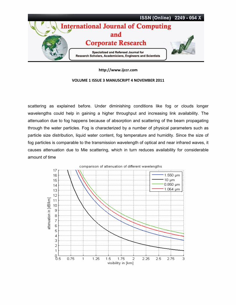
scattering as explained before. Under diminishing conditions like fog or clouds longer
wavelengths could help in gaining a higher throughput and increasing link availability. The
attenuation due to fog happens because of absorption and scattering of the beam propagating
through the water particles. Fog is characterized by a number of physical parameters such as
particle size distribution, liquid water content, fog temperature and humidity. Since the size of
fog particles is comparable to the transmission wavelength of optical and near infrared waves, it
causes attenuation due to Mie scattering, which in turn reduces availability for considerable
amount of time

http://www.ijccr.com
VOLUME 1 ISSUE 3 MANUSCRIPT 4 NOVEMBER 2011
Figure 5. Wavelength attenuation in dependence of visibility[9]
A very important point is the laser and eye safety. The shorter wavelengths are more restricted
in laser power than the longer wavelengths. Also attenuations caused by scattering have a
lesser impact for longer wavelengths.
SUMMARY
Free Space Optic offers solutions for current bottlenecks in communication technology; however
it does not come for free. The cost we have to pay is huge attenuation of the signal, mainly
caused by non-quantifiable factors, like weather conditions. Main limiting factors for FSO link
design are rain and haze. Atmospheric physics fundamentally limit range to less than 500 m.
REFERENCES
[1] Heinz Willebrand, and Baksheesh S. Ghuman,” Fiber Optics without Fiber “ IEEE [2001].
[2] Scott Bloom, “Physics of free space optics” [2002].
[3 ] Carter Moursund, ‘LEDs vs. Laser Diodes for Wireless Optical Communication’white papers
by ClearMesh Networks December 2006Scott
[4] Bloom,Eric Korevaar,John Schuster,Heinz Willebrand : Understanding the performance of
free-space optics, in Journal of Optical Networking, 2003
[5] Husagic Alma, Wajdi Al-Khateeb, “Effect of Weather Conditions on Quality of Free Space
Optics Links”, Proceedings of the International Conference on Computer and Communication
Engineering 2008

http://www.ijccr.com
VOLUME 1 ISSUE 3 MANUSCRIPT 4 NOVEMBER 2011
[6] Ales Prokes, Vladislav Skorpil,
“Estimation of Free Space Optics Systems Availability
Based on Meteorological Visibility” IEEE 2009.
[7] M. Saleem Awan, E. Leitgeb, S. Sheikh Muhammad, Marzuki, F. Nadeem, M. Saeed Khan,
C. Capsoni, “Distribution Function For Continental and Maritime Fog Environments For Optical
Wireless Communication”, IEEE Proceedings 2008.
[8] S. Sheikh Muhammad, P. Köhldorfer, E. Leitgeb, “ Channel Modeling for Terrestrial Free
Space Optical Links”, IEEE [2005].
[9] Thomas Plank, Erich Leitgeb, Markus Loeschnigg, “ Recent Developments on Free Space
Optical Links and Wavelength Analysis”, International conference on Space Optics and
applications, 2011
[10] S. Rajbhandari, Z. Ghassemlooy1, J. Perez, H. Le Minh, M. Ijaz, E. Leitgeb2, G. Kandus
and V. Kvicera, “ On The Study of the FSO Link Performance under Controlled Turbulence and
Fog Atmospheric Conditions” , ”, International conference on Telecommunications, 2011
[11] Kim, B. Mcarthur, and E. Korevaar, “Comparison of laser beam propagation at 785 and
1550 nm in fog and haze for opt. wireless communications,” Proc. of SPIE, vol. 4214, pp.
26-37, 2001

http://www.ijccr.com
VOLUME 1 ISSUE 3 MANUSCRIPT 4 NOVEMBER 2011