Free-Piston Engine - Department of EnergyFree-Piston Engine Peter Van Blarigan. Sandia National...
18
Free-Piston Engine Peter Van Blarigan Sandia National Laboratories 2011 DOE Vehicle Technologies Program Annual Merit Review Tuesday, May 10, 2011 Project ID: ACE008 Sponsors: Advanced Combustion Engine R&D and Fuel Technologies Program Managers: Gurpreet Singh and Kevin Stork This presentation does not contain any proprietary, confidential, or otherwise restricted information
Transcript of Free-Piston Engine - Department of EnergyFree-Piston Engine Peter Van Blarigan. Sandia National...
Free-Piston Engine
Peter Van BlariganSandia National Laboratories
2011 DOE Vehicle Technologies Program Annual Merit ReviewTuesday, May 10, 2011
Project ID: ACE008
Sponsors: Advanced Combustion Engine R&D and Fuel Technologies Program Managers: Gurpreet Singh and Kevin Stork
This presentation does not contain any proprietary, confidential, or otherwise restricted information
2
OverviewTimeline
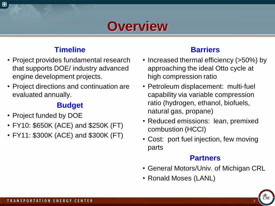
• Project provides fundamental research that supports DOE/ industry advanced engine development projects.
• Project directions and continuation are evaluated annually.
Budget• Project funded by DOE• FY10: $650K (ACE) and $250K (FT)• FY11: $300K (ACE) and $300K (FT)
Barriers• Increased thermal efficiency (>50%) by
approaching the ideal Otto cycle at high compression ratio
• Petroleum displacement: multi-fuel capability via variable compression ratio (hydrogen, ethanol, biofuels, natural gas, propane)
• Reduced emissions: lean, premixed combustion (HCCI)
• Cost: port fuel injection, few moving parts
Partners• General Motors/Univ. of Michigan CRL• Ronald Moses (LANL)
3
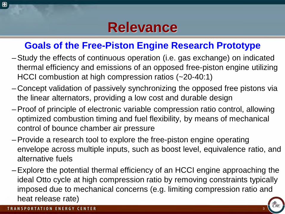
RelevanceGoals of the Free-Piston Engine Research Prototype
– Study the effects of continuous operation (i.e. gas exchange) on indicated thermal efficiency and emissions of an opposed free-piston engine utilizing HCCI combustion at high compression ratios (~20-40:1)
– Concept validation of passively synchronizing the opposed free pistons via the linear alternators, providing a low cost and durable design
– Proof of principle of electronic variable compression ratio control, allowing optimized combustion timing and fuel flexibility, by means of mechanical control of bounce chamber air pressure
– Provide a research tool to explore the free-piston engine operating envelope across multiple inputs, such as boost level, equivalence ratio, and alternative fuels
– Explore the potential thermal efficiency of an HCCI engine approaching the ideal Otto cycle at high compression ratio by removing constraints typically imposed due to mechanical concerns (e.g. limiting compression ratio and heat release rate)
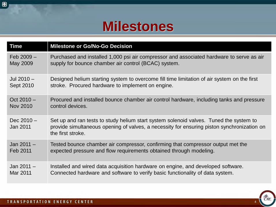
MilestonesTime Milestone or Go/No-Go Decision
Feb 2009 –May 2009
Purchased and installed 1,000 psi air compressor and associated hardware to serve as air supply for bounce chamber air control (BCAC) system.
Jul 2010 –Sept 2010
Designed helium starting system to overcome fill time limitation of air system on the first stroke. Procured hardware to implement on engine.
Oct 2010 –Nov 2010
Procured and installed bounce chamber air control hardware, including tanks and pressure control devices.
Dec 2010 –Jan 2011
Set up and ran tests to study helium start system solenoid valves. Tuned the system to provide simultaneous opening of valves, a necessity for ensuring piston synchronization on the first stroke.
Jan 2011 –Feb 2011
Tested bounce chamber air compressor, confirming that compressor output met the expected pressure and flow requirements obtained through modeling.
Jan 2011 –Mar 2011
Installed and wired data acquisition hardware on engine, and developed software. Connected hardware and software to verify basic functionality of data system.
4
5
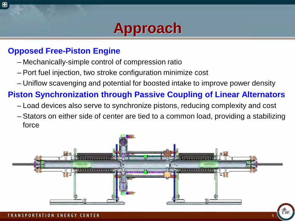
ApproachOpposed Free-Piston Engine
– Mechanically-simple control of compression ratio– Port fuel injection, two stroke configuration minimize cost– Uniflow scavenging and potential for boosted intake to improve power density
Piston Synchronization through Passive Coupling of Linear Alternators– Load devices also serve to synchronize pistons, reducing complexity and cost– Stators on either side of center are tied to a common load, providing a stabilizing
force
6
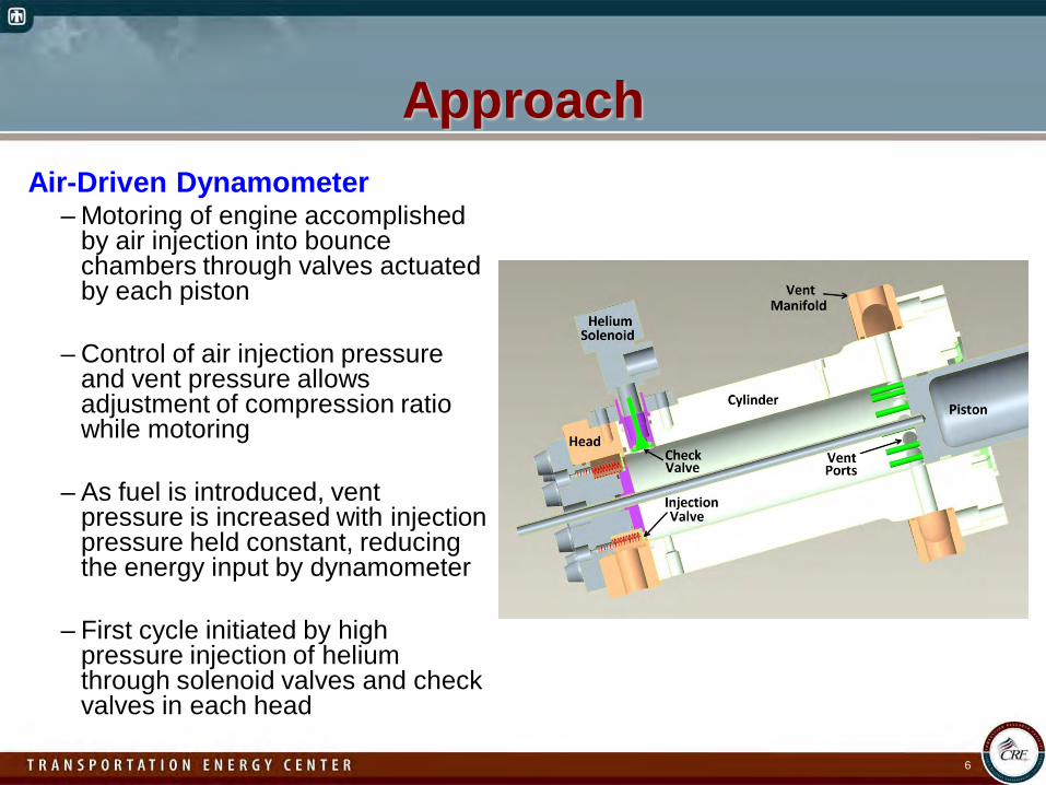
ApproachAir-Driven Dynamometer
– Motoring of engine accomplished by air injection into bounce chambers through valves actuated by each piston
– Control of air injection pressure and vent pressure allows adjustment of compression ratio while motoring
– As fuel is introduced, vent pressure is increased with injection pressure held constant, reducing the energy input by dynamometer
– First cycle initiated by high pressure injection of helium through solenoid valves and check valves in each head
7
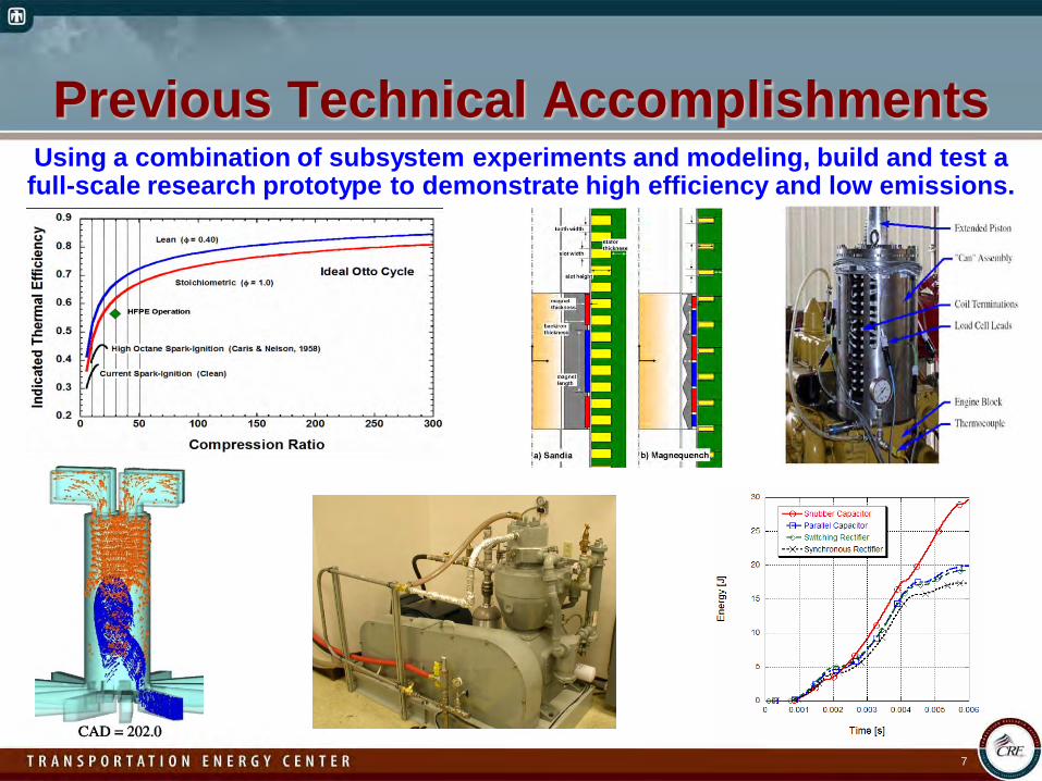
Previous Technical AccomplishmentsUsing a combination of subsystem experiments and modeling, build and test a full-scale research prototype to demonstrate high efficiency and low emissions.
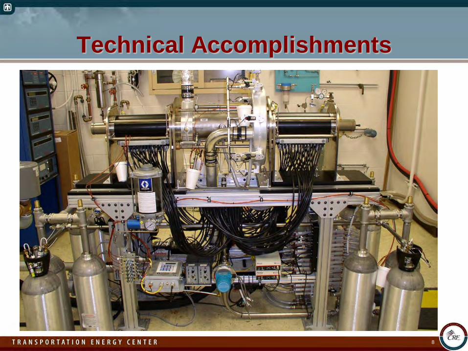
Technical Accomplishments
8
Technical Accomplishments
9
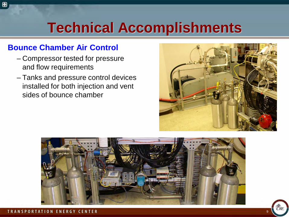
Bounce Chamber Air Control– Compressor tested for pressure
and flow requirements– Tanks and pressure control devices
installed for both injection and vent sides of bounce chamber
Technical Accomplishments
10
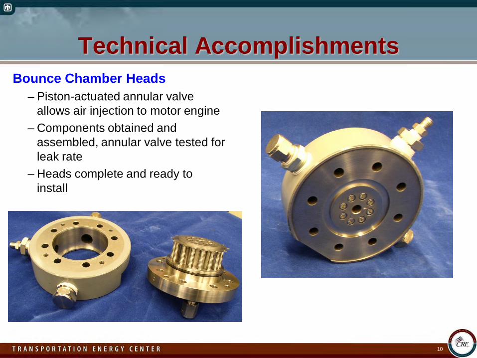
Bounce Chamber Heads– Piston-actuated annular valve
allows air injection to motor engine– Components obtained and
assembled, annular valve tested for leak rate
– Heads complete and ready to install
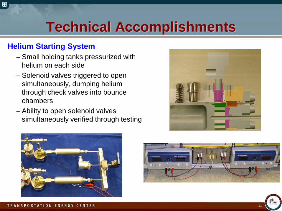
Technical AccomplishmentsHelium Starting System
– Small holding tanks pressurized with helium on each side
– Solenoid valves triggered to open simultaneously, dumping helium through check valves into bounce chambers
– Ability to open solenoid valves simultaneously verified through testing
11
Technical Accomplishments
12
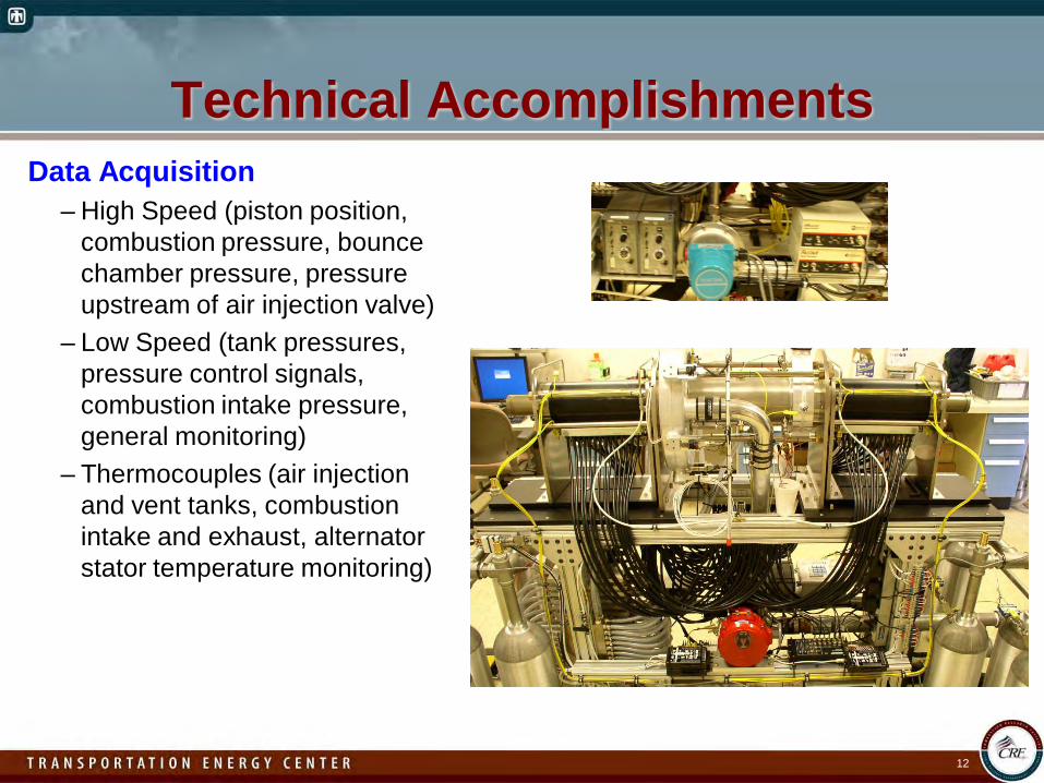
Data Acquisition– High Speed (piston position,
combustion pressure, bounce chamber pressure, pressure upstream of air injection valve)
– Low Speed (tank pressures, pressure control signals, combustion intake pressure, general monitoring)
– Thermocouples (air injection and vent tanks, combustion intake and exhaust, alternator stator temperature monitoring)
CollaborationsGeneral Motors / University of Michigan
– A new phase of collaboration with the GM/UM CRL began in May 2009.– GM/UM CRL will assess Sandia free-piston engine (FPE) potential with a model
built in a MATLAB/Simulink framework featuring 0-D thermodynamics, a linear alternator model, a bounce chamber air control model, and dynamic force balance.
– The model will be validated with respect to Sandia FPE experimental data and used to explore conditions outside the experimental matrix.
13
14
Future Work• Complete engine assembly
– Bounce chamber cylinders and heads– Helium starting system
• Utilize helium starting system to send pistons through one cycle– Before magnets are installed: Characterize piston friction at operating speed –
a key factor affecting passive coupling technique– With magnets installed: Test for first-cycle piston synchronization
• Motor the engine using air injection system– Test the stabilizing capability of the linear alternator coupling and assess
control of compression ratio• Perform combustion experiments
– Evaluate the free-piston linear alternator concept– Attempt to approach ideal Otto cycle operation at high compression ratio to
explore the limits of thermal efficiency– Operate with different fuels at a variety of compression ratios and equivalence
ratios to demonstrate the engine’s fuel flexibility
15
Summary• Free-Piston Engine (FPE) research prototype design
complete and fabrication nearing completion.•Helium-powered starting system designed to address fill
time limitation of air system on first stroke.•Bounce chamber air control components obtained and
installed on engine.•Data acquisition hardware installed, and software developed•Collaboration with GM/UM CRL on modeling of the Sandia
FPE prototype engine is ongoing.
Technical Back-Up Slides
16
17
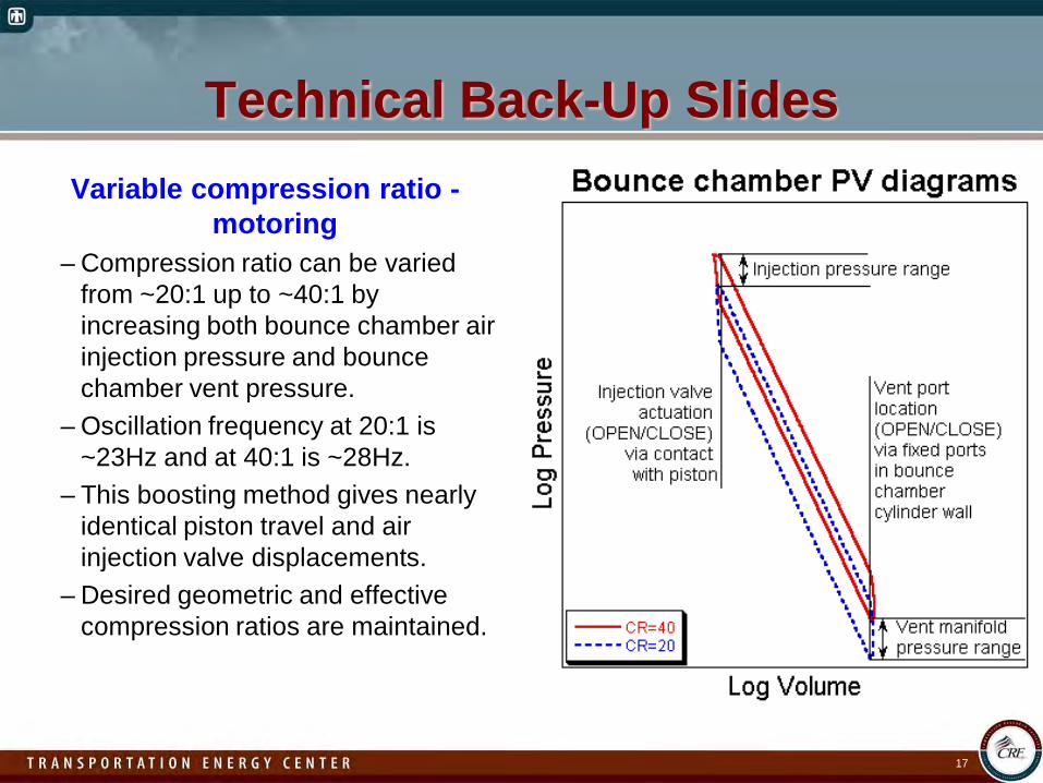
Technical Back-Up SlidesVariable compression ratio -
motoring– Compression ratio can be varied
from ~20:1 up to ~40:1 by increasing both bounce chamber air injection pressure and bounce chamber vent pressure.
– Oscillation frequency at 20:1 is ~23Hz and at 40:1 is ~28Hz.
– This boosting method gives nearly identical piston travel and air injection valve displacements.
– Desired geometric and effective compression ratios are maintained.
18
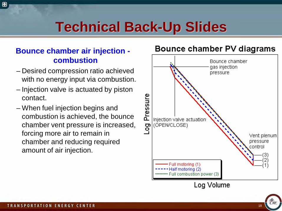
Technical Back-Up SlidesBounce chamber air injection -
combustion– Desired compression ratio achieved
with no energy input via combustion.– Injection valve is actuated by piston
contact.– When fuel injection begins and
combustion is achieved, the bounce chamber vent pressure is increased, forcing more air to remain in chamber and reducing required amount of air injection.