Free Form Sketching System for Product Design Using...
43
Free Form Sketching System for Free Form Sketching System for Product Design Using Virtual Product Design Using Virtual Reality Technology Reality Technology Supervisor Dr. Ali Supervisor Dr. Ali Akgunduz Akgunduz Presented by Hang Yu Presented by Hang Yu
Transcript of Free Form Sketching System for Product Design Using...

Free Form Sketching System for Free Form Sketching System for Product Design Using Virtual Product Design Using Virtual
Reality TechnologyReality TechnologySupervisor Dr. AliSupervisor Dr. Ali AkgunduzAkgunduz
Presented by Hang YuPresented by Hang Yu
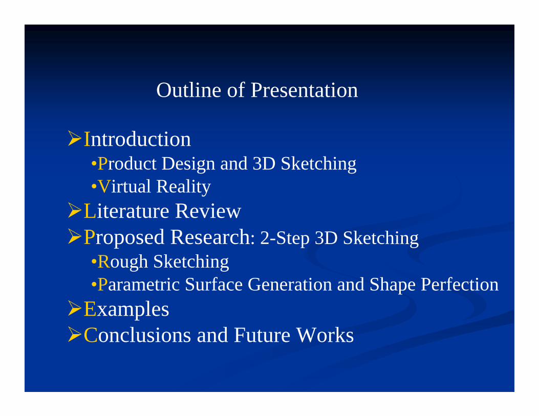
Introduction•Product Design and 3D Sketching•Virtual Reality
Literature ReviewProposed Research: 2-Step 3D Sketching•Rough Sketching•Parametric Surface Generation and Shape Perfection
ExamplesConclusions and Future Works
Outline of Presentation

Product Design ProcessDesign Process
CustomersCompetitors Future trend
Design Team
Engineer/Artist
Brain-Storming
CAD Design
Prototype
Engineering Verification Manufacturing
What can we do speed-up this process?
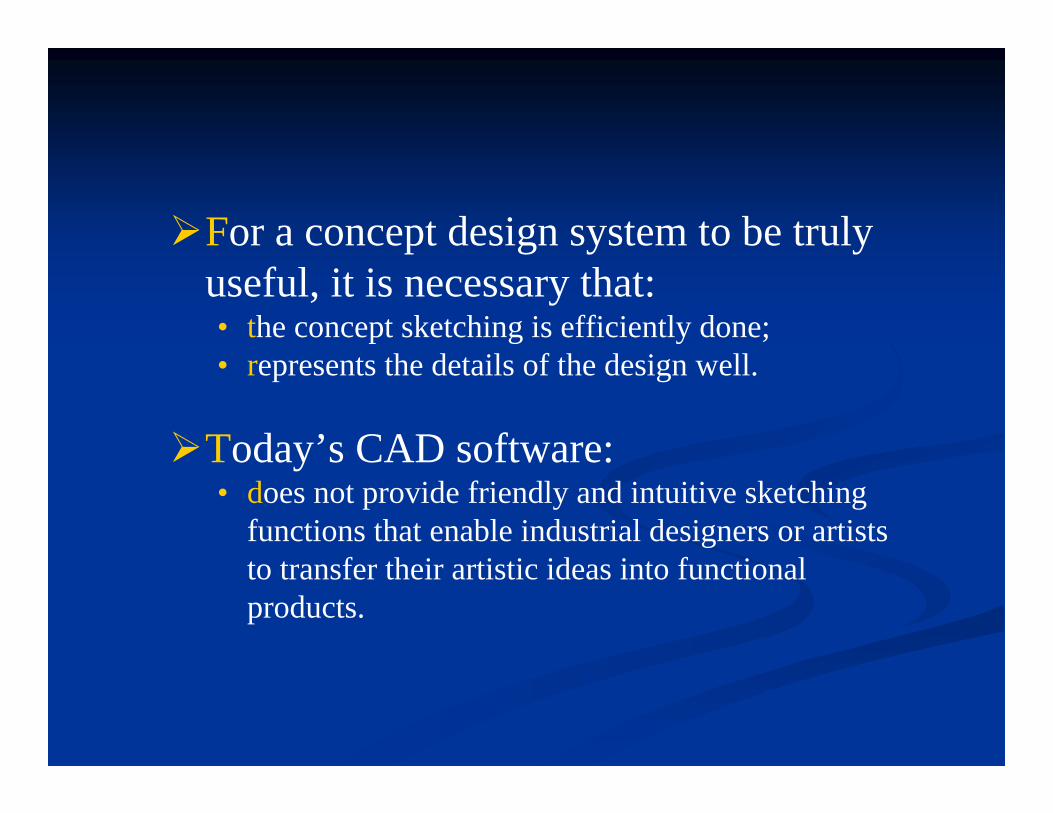
For a concept design system to be truly useful, it is necessary that:• the concept sketching is efficiently done;• represents the details of the design well.
Today’s CAD software:• does not provide friendly and intuitive sketching
functions that enable industrial designers or artists to transfer their artistic ideas into functional products.

Concept Design Tools:Due to the lack of resources, the 2D Sketching
is still the choice of the concept designers
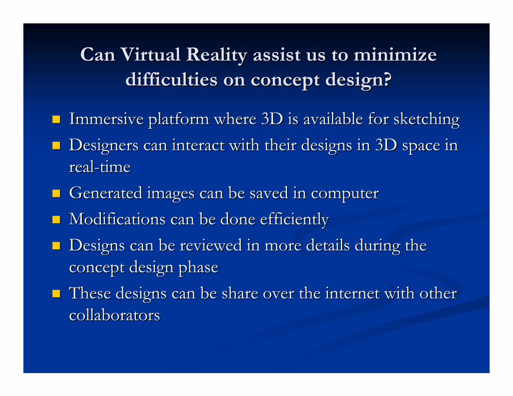
Can Virtual Reality assist us to minimize Can Virtual Reality assist us to minimize difficulties on concept design?difficulties on concept design?
Immersive platform where 3D is available for sketchingImmersive platform where 3D is available for sketchingDesigners can interact with their designs in 3D space in Designers can interact with their designs in 3D space in realreal--timetimeGenerated images can be saved in computerGenerated images can be saved in computerModifications can be done efficientlyModifications can be done efficientlyDesigns can be reviewed in more details during the Designs can be reviewed in more details during the concept design phaseconcept design phaseThese designs can be share over the internet with other These designs can be share over the internet with other collaboratorscollaborators

The difficulties and limitations of 2D sketching
a picture of a 3D object may tell a lot to an experienced a picture of a 3D object may tell a lot to an experienced designer but maybe nothing to others whom are designer but maybe nothing to others whom are involved in the product design process;involved in the product design process;further verifications still require 3D modeling;further verifications still require 3D modeling;design reviews include members from many different design reviews include members from many different backgrounds including customers.backgrounds including customers.
Combination of various backgrounds may not obtain equal understaCombination of various backgrounds may not obtain equal understanding nding from the 2D sketchesfrom the 2D sketchesModification requests takes long time to completeModification requests takes long time to completeProduct lead time unnecessarily increasesProduct lead time unnecessarily increases

3d Sketches3d Sketches
Sketching directly in the 3D world will reduce the product design cycle:
• Sketching errors are easy to correct;• Both technical and non-technical members will have the
full understanding of the design;• Outputs will directly be exported into CAD software;• Testing and verification is possible;
Minimize the time for design changes:• All the members of a design team can directly be involved
with the design from the beginning;• Possible design problems can be identified and resolved at
early stages of the design process.

“Conceptual Free-Form Styling on Responsive Workbench” by Geroid Wesche and Marc Droske:
The user draws curves (cubic B-Splines) directly in the Virtual Environment using a stylus as an input device;
A number of tool can be used to create the curves;
Curves later can be modified.
Previous Works
3D free-form styling on the Responsive Workbench
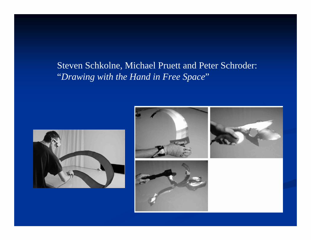
Steven Schkolne, Michael Pruett and Peter Schroder:“Drawing with the Hand in Free Space”
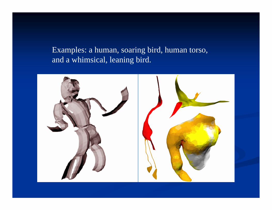
Examples: a human, soaring bird, human torso, and a whimsical, leaning bird.

Other Related Works
Sachs (1991) draw independent curves in 3D space where the user interface was captured using two 6-DOF electromagnetic trackers in a non-immersive virtual environment.
Baudel (1994) presented an approach that allows designers to present their ideas by hand motions in computer.
Dani (1999) developed a system called “Conceptual Virtual Design System” to improve the indispensable efficiency of conceptual design.
Bruno (2003) uses a pen to generate reference points for generating surfaces in their semi-immersive model.
Problems in current systemsProblems in current systems
The common characteristics of current methodsThe common characteristics of current methodsTo draw images into 3D space usingTo draw images into 3D space using
SplinesSplinesControl pointsControl pointsPolygon meshesPolygon meshes
Difficulties of these methods:Difficulties of these methods:Using a pen in virtual space is not naturalUsing a pen in virtual space is not naturalThere is no natural pointThere is no natural point--ofof--reference for designers reference for designers to grasp full understanding of his/her design to grasp full understanding of his/her design

Our ObjectivesDeveloping VR based sketching system:
Capture intention of designers/artistsTranslate their imaginations into geometric designsDirectly in 3D spaceFreely and unconstrained environmentFinally geometric shapes can be represented in mathematical forms where:
• Modification of images can be performed• Conversion to other popular CAD formats is possible
We prove that such system can be realized by using VR technology available today.

With our system:The conceptual design process can simply be
done in computerSeveral months of time on full-size mock-ups is
cut offThe process of product development is greatly
shortenedBetter product and faster development process
increase competitiveness of companies in today’s demanding marketplace

Our Solution to Improve Concept Design Process2-Step 3D Sketching System
Hardware/software used:OpenGL and Microsoft Visual Studio;5DT Data Gloves;Cybermind Hi-900 Resolution HMD
to realize the 2-step 3D free form sketching naturally and unconstraintly.

Simulation of the actual hand:Virtual Hand

2)Control Point Selection: Virtual Pen

3) NURBS Surface Generation
U and V are the knot vectors and P is the bidirectional control points.

4) Perfecting the surfaces

Why we choose to integrate polygon Why we choose to integrate polygon meshes with parametric surfaces?meshes with parametric surfaces?
Polygon meshesThe advantages are:
easy to generate;no mathematical knowledge is required;can be converted to any desired CAD format.
Drawbacks are:shapes can only be approximated, exact shapes cannot be captured when
curved surfaces exist;fitness to the desired shapes can only be possible with generation of
significantly higher number of polygon meshes;increased number of polygons consume significant amount of computer
memory and CPU time;rendering and animation of images becomes computational expensive;engineering analysis such as finite-element analysis is difficult if not
impossible;modification of the exiting geometries is difficult.
We can conclude that:
Although polygon meshes are desirable for creating 3D imagesThey are not accurate enough to represent and store themThey are suitable for capturing designers’inspirations at the beginning of the concept design
Parametric equations can define the exact location of a point on the object surface.
Advantages of representing objects using parametric equations are:less storage space is required;modification of surfaces is easy;conversion to desired CAD format is easy;computationally less expensive for animation;engineering analysis is possible (ex. finite-element analysis);rendering quality can be changed depends on the desired level.
The disadvantages are:designers should have a good understanding of the mathematical
fundamentals of the parametric equations; they are not user friendly for creating 3D shapes in VR.
We can conclude that:
Although parametric surfaces are good at representing 3D images
They are not the perfect choice to generate brand new computer images.
What is our system based on?What is our system based on?
Based on the above discussion, we developed our sketching technique by:
taking advantages of the strength of both polygon meshes and parametric surfaces deserting their disadvantages in separate design phases to realize the free-form 3D sketching process

We use polygon meshes attached to the virtual hands to construct the rough sketches of the designed product.
Step 1: Rough Surface Generation by Simulation User Hands in VR

Various complexity of images can be created by placing surface patches in 3D space
Step 1: Rough Surface Generation by Simulation User Hands in VR

We use parametric surface to represent product based on the previous rough sketches. For generating parametric surface, control points have to been generated first.
Selection of control points on a sketched surface using the virtual pen.
Step 2: Parametric Surface Generationa-Control Point Selection in 3D Space

Once sufficient number of points is selected on the planes of the sketches, parametric representations of the object are created.
Parametric surface based on rough sketching.
Step 2: Parametric Surface Generationb-NURBS Surfaces Interpolate the Control
Points

Naturally, these generated parametric surfaces may not satisfy the expectations of the designers. The virtual pen is used again to change the locations of these points by which the shapes of the surfaces are changed.
Changing the shape of the surface by changing its control points locations.
Step 2: Parametric Surface Generationc-Surface Perfection

Until the parametric surface satisfies the rough sketch which is the true inspiration of the designer
Therefore, the rough sketch is used as the benchmark during the perfection process
Step 2: Parametric Surface Generationc-Surface Perfection

Create a rough shape of the designed product using designer’s hands;
Select sufficient number of points using the virtual pen;Generate NURBS surfaces interpolating these selected
points;Modify parametric surfaces by:
•moving interpolating points using the virtual pen;•editing the data of these interpolating points directly in the saved file.
The summary of the steps described in this thesis in order to create a successful product is given below:

1) Rough sketching using virtual hands
EXAMPLES
A-Design of a Car
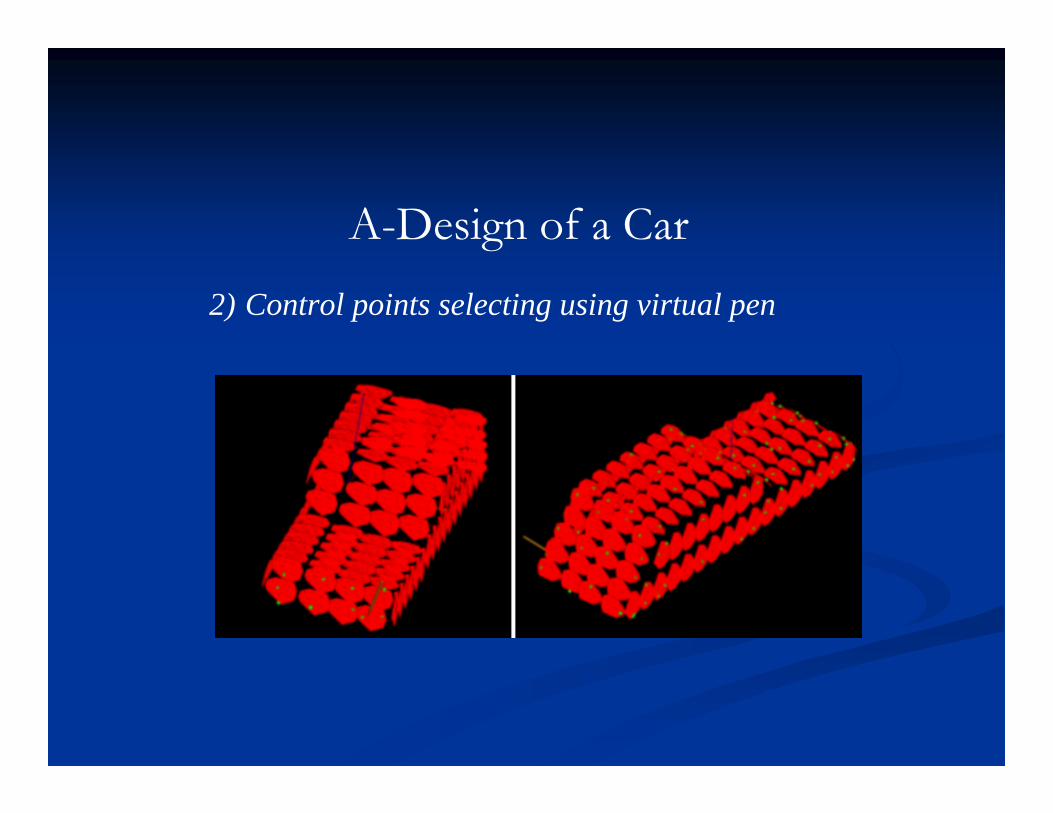
2) Control points selecting using virtual pen
A-Design of a Car
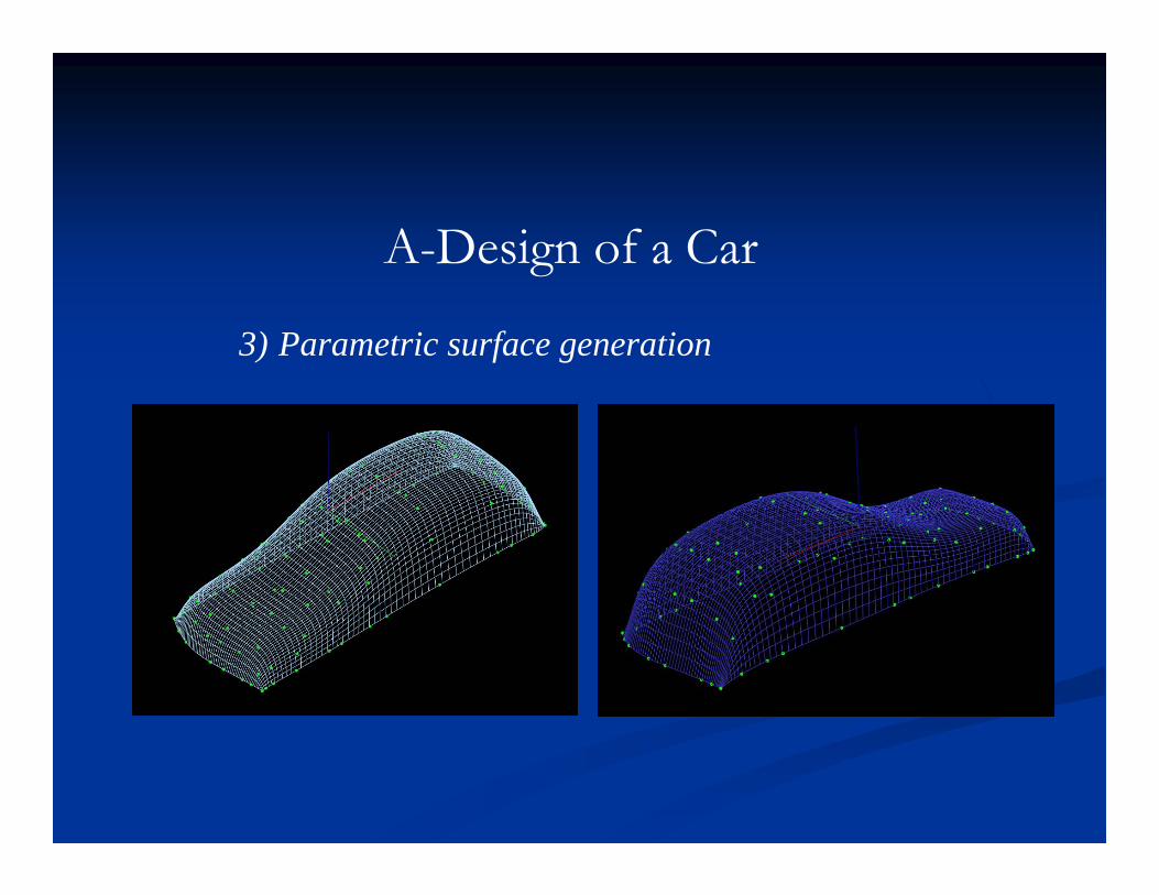
3) Parametric surface generation
A-Design of a Car
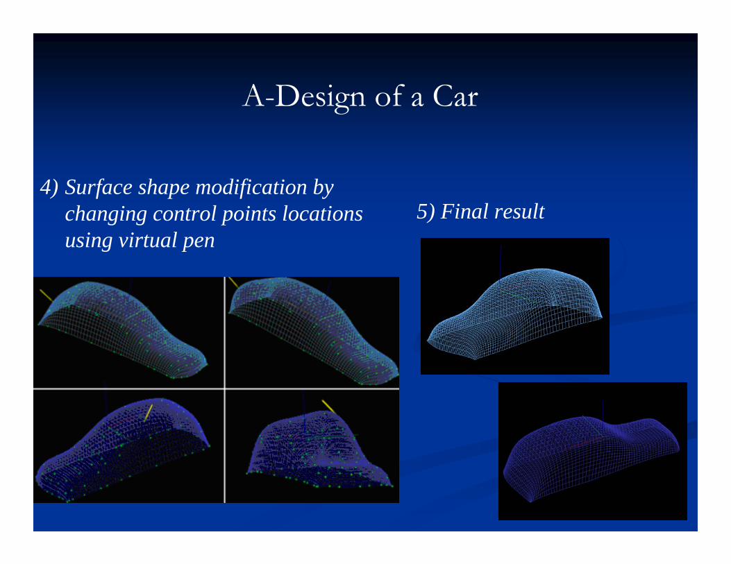
4) Surface shape modification by changing control points locations using virtual pen
A-Design of a Car
5) Final result

A-Design of a Airplane
Rough sketching.

Control points selection.
Surface generation.

Shape modification.
Final input.
Conclusions
2-Step 3D sketching system is very fast to catch the designers’ idea and inspiration;During the pieces of plane construction, designers are not dealing with complex surfaces;Images are made of small triangle groups and do not need much calculation.;This greatly fits for conceptual design;Final geometry is smooth and in mathematical form.Images can be converted to any desired CAD formatImages can be converted to any desired CAD format
Future Work
Voice recognition can be added to free both designers’ hands for design;
More intelligent algorithms are needed to deal with the parametric surface generating and modifying like:
•sharing same control points among geometries;•snapping and aligning separate geometries;
Haptic devices for touch and feedback should be added to give a natural feeling for surface modifying.

Questions?