FREE 444/ · NEW DYNAMIC MICROPHONE ... ASSEMBLED BATTERY CHARGER KITS CHARGER Consisting of Maine...
108
DECEMBER Practical 1961 IRELESS FREE 444/ THE CITIZEN BLUEPRINT for TRANSISTORISED 2-UNIT SUPERHET TUNER - At www.americanradiohistory.com
-
Upload
truongduong -
Category
Documents
-
view
213 -
download
0
Transcript of FREE 444/ · NEW DYNAMIC MICROPHONE ... ASSEMBLED BATTERY CHARGER KITS CHARGER Consisting of Maine...

DECEMBER Practical 1961
IRELESS FREE 444/
THE CITIZEN
BLUEPRINT for TRANSISTORISED
2-UNIT SUPERHET TUNER
- At
www.americanradiohistory.com

PRACTICAL WIRELESS December, 1961
$Wtentuhíaii This range of Stentorian loudspeakers, incorporating the patented cambric cone, was developed to provide reproduction that takes full advantage of the television and V.H.F. sound transmissions and high fidelity recordings now available. The cone of the loudspeaker is made from uncured cambric and bonded pulp, the whole being completely cured together and made into one composite cone.
Type Flux Density Price
8" H.F.8I6* 16,000 gauss £7.09
8" H.F.8I2* 12,000 gauss £4.5.6
8" H.F.8I0 10,000 gauss £3.3.6
I Type Flux Density Price
1.186 16,000 gauss £6.13.3
T.I2 tweeter 16,000 gauss £13.4.6
T.I0 tweeter 14,000 gauss £4.8.3
6" H.F.610 ! 10,000 gauss £2.12.9 Steel T.359 9,000 gauss £ 1.15.10 E2 15 Od recast tweeter '
MODEL H.F. 1016 IO" Unit H.F. 1016. 16,000 gauss. Instantaneous match- ing at 3, 7.5 and 15 ohms. Handling capacity 10 watts. Frequency response 30 c.p.s. to 15,000c.p.s. Bass resonance, 35 c.p.s.
Price £8.4.0 (inc. P.T.) Incorporates a universal impedance speech coil.
WHITELEY ELECTRICAL RADIO CO. LTD. MANSFIELD, NOTTS Telephone: MANSFIELD 1762 -5 London Office: 109 Kingsway, London, W.C.2
WA3
SPECIAL FOR THE "HAMS" RADIO STATION
Illustrated
inch detachable bit soldering instrument List No. 70
Combined Protective Unit with Wiper Abrasion Pad and Solder Reel List No. 700
Apply SALES & SERVICE
/ 1DCOL1 (Regd, Trada Mark)
ADCOLA HOUSE GAUDEN ROAD LONDON, S.W.4
Telephones: MACaulay 3272 -3101
British & Foreign Patents, Registered
Designs, etc.
Telegrams "SOLJOINT, LONDON"
Well paid to see the world A really interesting and worthwhile job as a Radio Officer in the Merchant Navy awaits you if you are the holder of a current P.M.G. certificate. Salary and allowances are good from the start, rising by regular incre- ments to well over the four figure mark with all found. Your job can take you all over the world, and you get generous annual leave besides off -duty time in foreign ports. Sea service offers ample opportunity to study for further technical qualifications and many well - paid shore appointments are open to you later on.
A tradition second to none Marconi Marine Radio Officers have a long and proud tradition of service extending back to -he early years of this century. Among them are to be found names hallowed in the history of the sea. Moreover, many men in the highest public and administrative positions today began their careers as Radio Officers in the Marconi Marine
Company.
Write for particulars to: F. E. ASH, Esq.
THE MARCONI INTERNATIONAL MARINE COMMUNICATION CO.
LTD., English Electric House, Strand, London, W.C.2 I
1 1
www.americanradiohistory.com

December, 1961 PRACTICAL WIRELESS 665
Tel: Mitcham 6201
Open Daily to Callers All Valves Brand New
and Fully Guaranteed
211 STREATHAM ROAD, MITCHAM, SURREY Special 24 Hour Express Mail Order Service
AC2PEN 211-
AC2PEN DD 211-
ACTP 321- ACVPI 1716 AZI IV- AZ3I I01- 1336 101- CI 1216 CBL31 211- CCH35 211- CL33 1816 CYI IS1- CY31 1519 D77 41- DAC32 916 DAF9I 716 DAF96 819 DCC90 1416 DF33 101- DF91 41- DF92 71- DF96 816 0F97 916 DH63 61- DH77 71- DK32 1116 DK9I 81- DK92 816 DK96 816 DL33 8r6 DL35 1016 DL92 716 DL93 71- DL94 81- DL96 816 EA50 21- EABC80 61- EAC91 41- EAF42 916 E834 216 EB41 716 EB9I 41- EBC3 21r- EBC33 416 EBC4I 91- EBC8I 101- EBF80 816 EBF83 816 EBF89 816 EBL2I 221- EBL31 2116 ECC34 151- ECC35 81- ECC40 211- ECC8I 519 ECC82 816 ECC83 716 ECC84 816 ECC85 81- ECC88 1716
RMI 513
RM2 716
RM3 719
RM4 141-
RM5 1916
14A86 17/6
ECC9I 41- ECFBO 816 ECF82 816 ECH3 2I1- ECH2I 221- ECH42 916 ECH35 101- ECHBI 81- ECH83 816 ECL80 91- ECL8I 101- ECL82 916 ECL83 121- EF6 211- EF9 211- EF22 141- EF36 41- EF37 81- EF37A 81- EF39 41- EF40 151- EF4I 81- EF42 101- EF50A 41- EF50E 316 EF80 51- 0F85 51- °F86 1016 EF89 91- EF9I 41- EF92 41- EF95 716 EF97 1216 EF98 101- EF183 181- £F184 141- EK32 816 EL2 211- EL3 211- EL6 211- EL32 416 EL33 101- EL34 151- EL35 101- EL37 1716 EL38 211- EL41 101- EL42 101- ELBI 1216 EL84 619 EL85 101- EL90 816 EL91 41- EL95 1016 EM80 816 EM8I 816 EM84 916 EM85 100- EY51 816 EY81 816 EY83 IV- EY86 816
METAL
I4RA 1-2-8-2
16RC 1-1-16-1
1 4R I-2-8-3
I8RA I-I-16-I I8RA I-2-8-I I8RD 2-2-8-I
EZ35 61- EZ40 71- EZ4I 71- EZ80 71- EZ8I 71- EZ90 71- EI148 21- FC2 211- FC2A 211- FC4 I51- FCI3 211- FCI3C 211- FW4/500 91- FW4/800 91- GZ30 1016 GZ32 1016 GZ33 1913 GZ34 1316 GZ37 1913 HABC80101- HL4IDD816 HL92 816 HLI33DD
101- HN309 201- 1W4/350101- 1W4/500 101- KT33C 81- KT36 17/6 KT55 1716 KT6I 916 KT66 151- KT76 101- KT81 IS1- KT88 211- L63 51- LN152 91- LN309 1216 LZ319 1216 MKT4 I7/6 MS4B 1716 MVSPEN
1716 MVSPENB
1716 MUI4 91- MX40 I51- NI8 81- N37 141- N78 1716 NI08 181- N308 201- N339 151- N369 10/6 OD3 51- OZ4 516 P2 101- PABC80131- PCC84 91- PCC85 916 PCC88 IV- PCC89 916
RECTIFIERS
1716 (FC31)
816
191- IFC31)
616 (FCI 16)
I11-
151- (FC 124)
PCF80 916 PCF82 71. PCF84 161- PCF86 151- PCL82 916 PCL83 I216 CPL84 1016 PCL85 161- PENA4 1716 PENB4 1716 PEN4DD
251- PEN4VA
1716 PEN36C211- PEN45 101- PEN45DD
2216 PEN46 51. PEN453DD
2716 PENDD4020
251- PL33 151- PL36 151- PL38 211- PL81 121- PL82 81- PL83 1016 PL84 91- PL820 181- PM24M 1316 PX4 151- PX25 251- PY31 151- PY32 1216 PY80 716 PY81 716 PY82 716 PY83 816 PZ30 1816 QS9510 101- QSI5015 101- R2 101- R3 101- R12 816 R16 1716 R19 191- R20 191- 5130 716 SP4I 316 SP61 316 SU2I50 251- SU2150A
251- 741 151- TDD4 1216 TDDI3C
1716 TH4I 241- TY86F 1216 U10 91-
14A97
I4A100
I6RD 2-2-8-I
16RE 2-I-8-1
I8RA I-I-B-I
U12 U14 U22 U24 211- U25 1216 U26 101- U27 U31 U35 1716 U37 1716 U43 816 U45 101- U47 1216 U50 716 U52 41- U76 716 U78 416 U191 151- U251 1216 U281 181- U282 1916 U301 2216 U329 1216 U339 I51- U403 101- U404 101- U801 291- UABC80 71- UAF42 816 UB4I 716 UBC41 8/6 UBC8I 101- UBF80 816 UBF89 716 UBL2I 211- UCC84 1016 UCC85 7r6 UCF80 1316 UCH21 211- UCH42 916 UCH81 81- UCL82 101- UCL83 1316 UF4I 716 UF42 716 UF80 71- UF85 716 UF86 1216 UF89 616 UL4I 816 UL44 211- UL46 1416 UL84 71- UL85 716 UM80 1016 URIC 151- UU6 191- UU8 211- UU9 716 UYIN 1216 UY21 1516 UY4I 716
251-
271-
121-
816
416
91- UY85 71- 91- VMS4B 1216 81- VP4 151-
VP4A 1716 VP4B 1716 VR10530 71-
81- VR15030 71- 91- VU39 91-
VUIII 216 VUI20 216 W61 I11- W76 51- W77 41- W81 61- W81M 61- X17 8/6 X18 91- X41 151- X6I 1216 X6IM 22/6 X65 1216 X76 1216 X76M 1216 X78 211- X79 211- Y61 101- Y66 916 Z63 716 Z66 101- Z77 41- Z152 51- ZDI7 81- ZDI52 8r6 OZ4 51- A7 1116 CI 816 C2 91- C3 916 C5 1016 D5 816 D6 101- H5 916 L4 51- LN5 416 NS 916 R5 716 S4 81- S5 716 T4 41- U5 519
2P 2419 3A4 51- 3A5 1016 3Q4 81- 3Q5 91- 3S4 71- 3V4 81- 5U4 41- 5V4 719 5Y3 8r6 5Y3GT 816 5Z4 916
5Z4GT 1216 6A7 91- 6A8G 816 6A8GT 1316 6AB8 91- 6A18 916 6AK5 51- 6AK8 716 6AL5 61- 6AM5 51- 6AM6 41- 6AN5 7r6 6AQ5 616 6AQ8 913 6AT6 61- 6AU6 91- 6138G 31- 6BA6 61- 68E6 61- 6BG6G 1716 6BH6 81- 6816 61- 6BQ7A 1216 68R7 1216 6BS7 1216 6BW6 71- 6BW7 51- 6BX6 51- 6C4 316 6C5GT 81- 6C6 616 6C9 1216 6CD6G 321- 6CH6 101- 6D2 41. 6D6 516 6E5 101- 6F1 10/6 6F6 619 6F11 I01- 6F12 41- 6F13 101- 6F14 101- 6F15 1216 6FI9 1216 6F23 1016 6F33 516 6H6 21- 6J5 416 615GT 416 616 316 617 51- 6J7GT 716 6K7 21- 6K7GT 8/6 6K8 5r- 6K8GT 916 6K25 181- 6L1 131- 6L6 716 6L18 I01- 6L19 1716
6LD20 141- 6P25 1016 61.28 1716
-6Q7 616 6Q7GT 816 6SA7 71- 6SG7 71- 6;H7 61- 6ìJ7 616 63K7 516 65L7GT 61- 651,17GT 516 6SQ7 816 6+.J4GT 101- 6iJ5G 716 6V6 416 6V6GT 81- 6X4 416 6X5 416 6XSGT 51- 6X6 151- 630L2 101- 7B5 1216 7B6 101- 7B7 816 7B8 81- 7C5 81- 7C7 01- 7C7 81- 2D3 151- 7D5 151- 7D6 151- 7D8 151- 7H7 7r6 7K7 816 'Q7 101- 7R7 121- 'S7 101- 7Y4 716 3D3 41- "38W6 1216
OCI 1216 0C2 1716 CFI I51- OF3 I51- OF9 12/6 OLDII IV- OLDI2 I01- OP13 151- 0P14 191- 018 I51- ID5 2316 2A6 616 2AH8 91- 2AT6 716 2AT7 51- 2AU7 816 2AX7 716 2AU6 1716 28A6 716 2BE6 716 2BH7 101-
2C8 816 2J5GT 41- 217GT 816 2K7GT 51- 2K8GT 101- 2Q7GT 616 2SA7 816 2SK7 61- 2SQ7 816 2SL7 81- 2SN7 101- 3D3 1216 4H7 101- 4R7 101- 4S7 151- 9AQ5 81- 986G 211-
20D1 101- 20F2 1716 20L1 1716 20P1 251- 20P3 251- 20P4 221- 20P5 251- 2186 121- 25A6 81- 25L6 81- 25Y5 81- 25Z4 716 25Z5 81- 25Z6 81- 27SU 1716 30C1 916 30F5 101- 30FLI 1016 30L1 916 30L15 1116 30P4 211- 30P12 101- 30P16 91- 30PLI 151- 30PL13 1216 35L6GT 816 35W4 716 35Z3 10/6 35Z4 716 35Z5 816 40SUA 151- 4ISTH 211- 42 1216 5005 101- 50L6 816 50CD6G
3616 53KU 1216 75 81- 78 716 80 91- 85AZ 1216 1858T 301- 305 916 807BR 51-
SPECIAL OFFER EABC80 61-, EAC9I 41-, E891 a1-, EBF89 816, ECC81 519, ECC85 81-, ECC9I 41-, ECH8I 81-, EBC33 416, EF39 41-, EF50 316, EF80 51-, EF85 51-, EF9I 41-, DF9I 41-, EL84 619, PCC89 916, PL84 91-, UABC80 71-, UBF89 716, UF41 716, U121 816, UF89 616, UL84 71-, UY85 71-, W81 61-, OZ4 51-, 5U4 41-, 6AQ5 6.6, 6BA6 61-, 68E6 61-, 6D2 41-, 6K7 21-, 6K8 51-, 6L6 716, 6Q7 616, 6SL7 616, 6SN7 516, 6V6 416, 6X5 51-, 803 41-, 807 51- 12AT7 51-, I2AH8 91-, 12BA6 716, 128E6 716, 12K7 51-, 12Q7 616.
TERMS OF BUSINESS C.W.O. or C.O.D. 219 PACKING CHARGE ON ALL C.O.D. ORDERS. POSTAGE 6d. PER VALVE
OBSOLETE VALVES A SPECIALITY. QUOTATIONS GIVEN ON ANY TYPE
NOT LISTED
www.americanradiohistory.com

666 PRACTICAL WIRELESS December, 1961
TUBULAR BAFFLE EXTENSION SPEAKER MODEL TS.30
Mounts vertically- mounts horizontally -mounts on wall -sits on desk) Designed for use with transistor radios, valve radios, car radios, amplifiers, auxiliary speakers in Hi -Fi and numerous other applications where quality reproduction of sound is required. The cabinet is finished in beige leather, with contemporary gold baffles at
S7'6 each end. Complete with 12 ft. extension cord fitted with miniature plugs, individually cartoned and guaranteed. Size: 94in. x 34 in. diameter.
P. & P. 216
NEW DYNAMIC MICROPHONE
MODEL DM -175 Beautifully designed and attractively fin- ished, lightweight dynamic mic- rophone complete with stand. Output impedance 1K ohm, fre- quency response 150 -9000 c
PpD.s. feet for
Sensitivity all applications
and offered at only 49/8. p. & p. 2/6
3 -WAY SLIM CRYSTAL MICROPHONE MODEL 100C
May be hand held, stand mounted or suspended by Lavafler Cord. Response 60- 10,000 Cps. Built in on/off switch. Output level - 52db. Omni- directional head. Clips on or off standard stand adaptor, permitting tilting for multi -angle use. Satin chrome finish complete with 7ft. shielded cable, stand adaptor and Lavaher Cord. ONLY 39/6 P. & P. 2/6. (Stand 8/6 extra.)
LAPEL MICROPHONE MODEL M178
Precision engineered Crystal Microphone -for lapel or hand use. Only 111n. dia- meter Exceptionally sensitive. Chrome plated case and clip includes 5ft. shielded cable. Only 17/6. P. & P. 1 / -.
CH. 805 CHROME MINIATURE PLUGS AND SOCKETS
Size: plug barrel l', socket I'. These will give your equipment that expert finish! 8/6 Per Set.
P217A. MINIATURE 211a. SPEAKER. A miniature speaker that out- pertormsail others. Designed to meet today's require- ments for transis- tor, miniature and sub -miniature ap-
lfcatione. Size 29ín, eq. sun. deep. Voice coil impendance: 8 ohms. Freq. range: 150 -5000 c /s. Power: 200mW. 16/8.2. & P. 1 / -.
SUPER TRANSISTOR RADIO With Miniature Speaker. Simple instructions enable anyone to build this miniature radio. Gives reception over the entire broadcast band. Each kit is supplied with all latest miniature parts including: * two transistors * ferrite rod * speaker * coloured plastic
instructions. Size illustrated
ONLY í17Ig PBatery 1!- ex.
Made available owing to public demand)
EP.10K MULTI -METER 10.000 O.P.V. on BOTH A.C. apd D.C. Ranges: D.C. Voltage: 0-6- 30- 120-!00 -1,200 v. (10,000 o.p.v.). A.C. Voltage: 0-6 -120- 800 -1,200 v. (10,000 o.p.v.). D.C. Current: 0- 120µA, 0- 12-300 mA. Resistance: 0-20E. 0-2 Meg. (150 ohm, 15K at centre scale). Capacit8
v. ). ance: 0.005 to 0.15µF (at
Dec AA.
ibels: -20 to +Buds- (600 ohms 1 mW., odbm -0.775 v.). Accuracy: D.C. voltage and cur- rent +2% f.e. A.C. Voltage + 4% f.s. Resistance ±3% of total scale length. Size: 4á1n. x 3ú1n. x lin. Complete with test leads, battery and in- structions. Only £5.19.8.
MINIATURE CLEAR PLASTICS PANEL
METERS "S" METER MODEL SR. 2P. Stan- dard "Ham" Signal strength indica- tor. Calibrated in "S" units from 0-9 with scale terminating in + 10 to + 30 db calibrations. Additional full scale calibrations of 0-5 + 0-10 in linear scale divisions. A "must" for radio amateurs for conversion of any Communication Receivers wf th A. V.C. action to give calibrated signal strength action. 35/- VU METER MODEL VR. IP. Calibrated and damped in accordance with standard VU Meter Practice. Upper scale reads -20 to +3VO. Lower scale 0 -100% modulation. Uses precision carbon film multiplier resistor and full wave rectifier. 42/6. DC MICROA.M-METERS Model MR.25 0 to 50 uA. 39/6
Model MR.250 0 to 500 uA. 3216
DC MILLIAMMETER Model MR.21 0 to ImA 27/6 All models Individually Boxed and Fully Guaranteed. P. & P. 2/6 each.
SF -20 RADIO HEADPHONES Hi- impedance- 2,000 ohms -general use headset. Black and Ivory plastic cased electromag- netic units with adjustable head- band for comfort- able fit. Individual listening for all types of applica- tions. Individually packed, with flexible cord att- ached, 14/6. Post paid.
MINIATURE Fully Guar enteed and complete with trans- parent ear insert. 3 feet cord, minia- ture ping and socket. CR-5 High imp. crystal MR-4 Low imp. magnetic
EARPHONES
8 Each Post 1/-
TRANSISTOR SPECIAL! 5K. EDGEWISE MINIATURE VOLUME CONTROL MODEL K2. I0, with switch and ivory knob. As used in all miniature transistor radios. 4/6 each.
PVC. 200 TRANSISTOR MINIA- TURE 2 -GANG TUNING CON- DENSERS. 2089F. As used in latest translator sets. Capacity: Aerial section 7- 200pF, Oso. section 7.87pF. Trimmer capaeltY more than 69pF. Q factor: more than 200 at SbpF 10 Mc /s. Size 1 x 1 x fin. PRICE 12/6 each.
SUB -MINIATURE TRANSFORMERS
Ideal for miniature transis- tor portables, etc. Driver Model LT44: Primary: 20k. Secondary: Ik. Centre Tap- ped. Ratio: 5 : 1. Output Model LT700: Primary: 1.2K. Centre Tapped. Output: 3.2 ohms. Ratio: 2 : 1, complete with detailed instructions. Only 9/6 per pair. P. & P. 116.
All Transistor 2- STATION INTERCOM and Baby Alarm Here is an Intercom system for both calling and conversing which uses the highest quality transistors and is operated from a single battery. May be used for multi- purpose applications especially where there is no local electrical supply and also where voltage fluctuations are severe. Specially suited for use in offices manufacturing plants. hotels, restaurants, residences and wherever conversa-
tion is required between two or more locations. Ideal Baby Alarm. Brief Spec: 3 transistors. 20%mW output, 9 v. battery, built-in 211.n. speakers. The Master station incorporates individual volume control to ensure perfect speech re- production. The Sub -station Incorporates a unique "buzzing" call system which ensures maximum efficiency. S.A.E for further details.
Complete with battery and 60 it. of wire.
MAIL ORDERS TO fE (DEPT. P.). 82a COPTIC STREET.
LONDON, W.C.1
CALLERS WELCOME AT
87 TOTTENHAM COURT ROAD, LONDON, W.I MUS 9808
www.americanradiohistory.com

December, 1961 PRACTICAL WIRELESS
PYE COMMUNICATION RECEIVERS World coverage on these famous Communication Receivers. They are the simplest type to use yet bring in stations that will amaze you. The ideal domes- tic receiver for medium wave during the day with Amateur stations at night. All have been converted to 230 v. A.C. mains and are guaranteed to work Immediately. Incorporate Wave Switch, Audio gain aerial trimmer, high and low tone control, station locking device, aerial and earth inputs, speaker out- put sockets. etc. Size 17 x 8 x 941n. Black crackle finish front panel. On demon- stration at 87 Tottenham Court Road. P.C.R.3. Medium wave and 2 -7 and 7 -23 Mc /s. Less speaker. Few only. Brand new P.C.R.2. Medium and long waves and 6-23 Mc /s. Less speaker. P.C.R. Medium and long waves and 6-18 Mc /s. With speaker.
HI -F1 HEADPHONES These miniature 111 -
F! phones use high quality permanent magnetic speakers with regu- lated voice coil. The soft rubber
ear moulds give correct spacing for optimum acoustic load. Each unit has a built -in miniature Hi- FI transformer to ensure the finest music and voice reproduc- tion. Supplied free is a small transformer unit which steps impedance up to 4000 ohms. Only 15/- P. & P. 2/6.
HOOVER ROTARY TRANSFORMERS
12 v. input, 500 v. output at 65 mA. or 6v, input, 250 output at 5 mA.
Only 10/8 each. P. & P. 2/-
SPARE VALVE K I T Here's a gift for all 38 and 18 Set own- ers! Case contain - ARP12 & I ATP4 valves. Only 10/- P. & P. 2/6
-_'-1
lin;jr 11i
IMP ! I
nilr. II
I!j :TR IL^'
U.S.A. DYNAMOTORS Manufactured by EICOR. Input. 12 v. output 4110 v. at 180 mA. Size 7 x 4 x 441n. Brand new 45/ -. P. & P. 3/6.
£12.12.0 £8.19.6 £9.19.6 Caeach type
(All the above P.C.R. Receivers have been completely reconditioned).
667
12v. VIBRATOR PACK (Supply Unit No. 9.) As used with P.C.R. Receivers giving 250 v. output at 80 mA. Fully smothed. Size 10 x 8 x 61n.
ONLY 255/. EACH. P. & P. 5/ -,
19 SET Mk. III POWER SUPPLY With 2 dynamotors. H.T.31. 12 v. input, 250 v. output at 125 mA. H.T.32. 12 v. input. 490 v. output at 60 mA. DON'T MISS THIS BUYI
ONLY 25/, P. & P. 5 / -,
PORTABLE TRANS /RECEIVER SETS
Consisting of trans /receiver covering 7.4-9 Mc /s range up to 10 miles, complete with 5 valves headphones, microphone. junc- tion box and Eft. telescopic aerial. Only requires 120 v. and 3 v- dry battery. TWO FOR £8. Post Free. SPECIAL 135 V. H.T. BAT - TERIES. Ideal for above. 12/8 each.
PaaBOC('ET BINOCULARS
Precision all -purpose Pocket Binoculars centre focus-aligned lenses - brilliant de- sign - carry them everywhere for sport. theatre, etc, -open and close instantaneously. Terrific value at only 3/6.
12'
RELDA OFFERS THE FINEST SURPLUS AERIAL MAST AND INSTALLATION OF ALL TIME!
This 30ft. mast can be used as a complete aerial by fixing the neavy duty insulator at the base or just as a mast with the insulator at the top holding the 12ft. Aerial Whip giving a
rt
height of 42fc. The 12ft. whip can be used separately if re- quired. Complete kit comprises:
Complete installation offered at ONLY
65 1- i rr rrr s5 ,,,,,.
Carr.
- nxF.uwi é'tWK,a.
I Large Canvas Bag. 1 Metal Carrying 10 Rods aft. x ¡in. dia. Case.
I Heavy Duty Insu- I Hammer. lator. I Small Canvas Bag.
I Large Base Stake. I Aerial Adaptor. I Small Stake with 10 Ground Stakes.
Insulator.
Also all necessary Guy Ropes, Link Insulators, etc.
AERIAL VARIOMETERS These magnificent instruments will enable you to receive maximum signal strength on all S.W. receivers. Precision, cali- brated control 12 /6. P. & P. 2/6.
V.H.F. MOBILE AERIAL ' and base, with PYE connections. 27ín. overall, as used by Taxis, Police. etc.. 7/8.
U.S.A. WHIF'AERIALS 12ft. 10/ -. COME LETE HEAD- PHONE and MICRO- PHONE ASSEMBLY 10 / -. P. & P. 3/6.
ACCUMULA- TORS. 2 volts 16 A.H. (unsplliabie). Ideal for 8 and 12 volts supply, etc. Brand new. Original cartons. Size 4ín. x 71.n. x 21n. 5/8 each. P. & P. 1/6. 3 for 15 / -. P. & P. 3/6. 6 for 27/8. P. & P. 5/ , No. I MOVING COIL MICRO- PHONE INSERTS. Ultra sen- sitive. As used in many Govt. Microphones! Size liin. dia. x 15- deep. Brand new and guaran- teed. 8/6 each.
CRYSTAL MICROPHONE INSERTS MODEL MC.1. Precision disc type crystal microphone cartridge. Output: - 53dB Response: 100-6,000 c.p.s. PRICE 8/6.
Fantastic Scope Buy! DOUBLE TClil: INDICATOR
Complete In black crackle case size 11 x 7 x 1311ns. Contains 2 new 5FP7 Tubes. All controls accessible on front. All con- nections at rear. Thousands already converted for TV Monitoring. Brand New. ONLY 30/. P. & P. 5/ -, FEW REMAIN!
MAIL ORDERS TO (DEPT. P.), 32a COPTIC STREET,
LONDON, W.C.1
CALLERS WELCOME AT 87 TOTTENHAM COURT ROAD, LONDON, W.1 MUS 9606
www.americanradiohistory.com

668 PRACTICAL WIRELESS December, 1961
BENTLEY ACOUSTIC CORPORATION LTD. 38 CHALCOT ROAD, CHALK FARM, LONDON, N.W.I. Telephone: PRIMROSE 9090
EXPRESS POSTAL SERVICE. ALL ORDERS DESPATCHED SAME DAY AS RECEIVED. TELEPHONE AND TELEGRAM ORDERS FOR CASH ON DELIVERY SERVICE ACCEPTED UP TO 3.30 P.M.
0A2 1716 0B2 1716 OZ4 51- IA5 61. IA7GT 121- IC5 1216 ID6 1016 1G6 1716 IHSGT 1016 IL4 316 ILD5 51- ILNS 51- INSGT 10/6 IRS 616 154 91- 155 6f- 1T4 3/6 IUS 6f- 2P 27/2 3A4 61- 3A5 1016 3B7 1216 3D6 51- 3Q4 716 3Q5GT 916 354 71- 3V4 716 5R4GY 1716 5114G 616 5V4G 101- 5Y3 616 5Z3 2015 5Z4G 9'- 6A7 10/6 6A8 91. 6AC7 41- 6AG5 5 6 6AG7 716 6AK5 81- 6ALS 41- 6AM6 416 6AQ5 716 6AT6 71. 6AU6 101- 6B8 51- 6BA6 716 68E6 61- 6BG6G23110 68H6 81- 6816 6'- 68Q7A 15f. 60R7 1216 6BR8 1911 6BW6 8/6 613W7 61- 6C4 51- 6C5 616 6C6 616 6C9 1316 6C10 9'- 6CD6G 3715 6CF16 9f- 6D6 6/6 6E5 1216
6F1 2712 6F6G 7/- 6F12 416 6F13 1116 6F23 10/6 6F24 1216 6F33 716 6H6 31- 615 5'- 6J6 516 617G 61- 6J7GT 1016 6K7G 51- 6K7GT 61- 6K8GT 1016 6K8G 616 6K25 2015 6L1 23/10 6L6G 81- 6L6M 916 6L7GT 716 6L18 131- 6LD20 1614 6N7 81- 6P28 2712 6Q7G 616 6Q7GT 111- 6R7G 101- 6SA7GT 816 6SC7 716 6SG7GT 81. 6S1-17GT 8/- 6517GT 81- 65K7GT 6f- 6SL7GT 616 6SN7GT 56 6SQ7GT 91- 6SS7GT 8f- 6U4GT 1216 6Ú5G. 716 61.J7G 816 6V6G 7f- 6V6GTG 8f- 6X4 Sr - 6X5GT 61- 6/3012 101- 7B7 816 7C5 81- 7C6 81- 7H7 81- 7R7 1216 7S7 916 7V7 816 7Y4 716 8D2 316 9BW6 1518 9D2 41- 10C1 131- 10C2 2712 IOFI 27/2 IOLDII 1614 10P13 15'- 10P14 19/9 12A6 51-
12AC6 1518 I2AD6 1718 12AE6 1413 I2AH7 81- I2AH8 12/6 12AT6 716 12AT7 61- 12AU7 616 12AX7 716 12BA6 81- 128E6 9/- 12BI-17 2119 12J5GT 416 1217GT 916 12K5 1814 12K7GT 516 I2K8GT 141- I2Q7GT 51- 12SA7 816 125C7 816 125G7 71- 12SH7 8/6 12517 816 12SK7 6/- 12SQ7 1116 125R7 816 12Y4 1016 19AQ5 1016 19H1 101- 20DI 1518 20F2 2712 20L1 27/2 20P1 2712 20P3 23110 20P4 2712 20P5 23110 25A6G 1016 25L6GT 101- 25Y5G 101- 25Z4G 9/6 25Z5 916 25Z6G 101- 27SU 2015 2807 7f. 30C1 81- 30F5 61- 30FLI , 101- 30L1 -° 8f- 30L15 1116 30P4 121- 30P12 716 30PLI 10/6 30PLI3 13/6 35A5 21/9 35L6GT 9'6 35W4 7/6 35Z3 1911 35Z4GT 61- 35ZSGT 9f- 43 IO'- 5005 10'- 50CD6G
3715 50L6GT 9/6
77 81- 78 616 80 91- 83 151- 85A2 161- 90AG 6716 90AV 6716 90C1 161- 90CG 37/6 101 1316 15082 181- 185BT 341- 304 10/6 305 1016 807 716 956 3/- 1821 171- 4033L 1216 5763 12/6 7193 51- 7475 76 9002 5/6 AC /PEN
5 -pin 23110 7 -pin 151-
AC2PEN/ DD 1216
AC6PEN 7/6 AC /TP 341- ATP4 5f. AZI 1911 AZ31 101- AZ4I 14/3 B36 151- BL63 716 CI 1216 CIC - 1216 CBLI 2712 CBL3I 23/10 CCH3523110 CK506 616 CL33 19/9 CV63 10/6 CYI 19/1 CY3I II/- 015 1016 DAC32 10/6 DAF9I 6f- DAF96 816 DD4I 14/3 DET25 716 DF33 1016 DF66 151- DF91 316 DF96 8/6 DF97 91 - DH63 6/6 DH76 51. DK32 121- DK9I 616 DK92 9/. DK96 816 DL33 916 DL66 17'6
DL68 151- DL72 I5'- DL92 71- DL94 716 DL96 816 DM70 716 E8OF 301- E83F 301- EI80F 3416 EA50 2f- EA76 916 EABC80 91- EAC9I 4/6 EAF42 91- EB34 216 E841 816 EB9I 41- EBC3 23110 EBC33 51- EBC4I 816 EBC8I 81- EBF80 9'- EBF83 1413 EBF89 916 EBLI 3016 EBL21 23/10 EBL31 23110 EC52 516 EC54 61- EC70 12/6 ECBI 2716 EC92 13/7 ECC32 56 ECC33 8/6 ECC34 2512 ECC35 816 ECC4023/10 ECC8I 61- ECC82 616 ECC83 716 ECC84 91- ECCB5 816 ECC88 181- ECF80 10/6 ECF82 1016 ECF86 2015 ECH3 2712 ECH21 23110 ECH35 616 ECH42 91- ECH81 91- ECH83 14/3 ECL80 91- ECL82 1016 ECL83 1919 ECL86 171- EF9 23110 EF22 141- EF36 41- EF37A 8f- EF39 5f6 EF40 IS'- EF4I 91- EF42 1016
EF50(A) 71- EF50(E) 51- EF54 51- EF73 1016 EF80 61- EF85 61- EF86 1016 EF89 91- EF9I 416 EF92 416 EF97 1317 EF98 1317 EFI83 1911 EF184 1216 EK32 816 EL32 51- EL33 1216 EL34 151- EL38 2712 EL4I 91- EL42 1016 ELBI 17'. EL83 20/5 EL84 716 EL85 1413 FF L86 1718
91 51- L95 10/6
EL820 1911 EL821 2712 EL822 1916 EM34 ,9/6 EM7I 23/10 EM80 91- EM8I 91- EM84 10/6 EM85 17f8 EN31 531- EY51 91- EY83 I7/- EY84 141- EY86 9'- EZ35 61- EZ40 7'- EZ41 71- EZ80 71- EZ81 7/. FC4 151- FW4/500816 FW4/800 8/6 GU50 4116 GZ30 91- GZ32 10 /- GZ33 2015 GZ34 14/- GZ37 20/5 HABC80
1316 HL2 716 HL23 1518 HL23DD 716 HL42DD
1919 HN309 2S'2
HVR2 201- HVR2A 6'- KF35 8'6 KL35 8'6 KLL32 25'2 KT2 51- KT33C 101- KT36 3017 KT41 23110 KT44 1216 KT61 1216 KT63 7/- KT66 I5/- KT8B 241- KTW6I 616 KTW62 716 KTW63 616 K::41 81- KTZ63 716 L63 61- MHL4 716 MHLD6 1216 ML4 816 MS48 23/10 MUI2 /14 81- N37 23110 N78 2015 NI08 23/10 N308 21111 N339 151- P61 316 PABC801413 PCC84 8f- PCC85 916 PCC88 181- PCC89 1116 PCF80 8f- PCF82 1016 PCF84 171- PCF86 151- PCL82 101- PCL83 1016 PCL84 1216 PCL85 171- PCL86 171- PENA423110 PEN4DD
2712 PEN25 416 PEN45 1916 PEN46 7/6 PEN383
23/10 PEN /DD
4020 341- PL33 19/9 PL36 121- PL38 2712 PL8I 1016 PL82 716 PL83 91- PL84 13'. PL820 1911 PM84 1718
PX4 1016 PY3I IV- PY32 1216 PY80 716 PY8I 816 PY82 71- PY83 816 PY88 1317 PZ30 2015 QP2I 71- QP25 1416 QSI50 /I5
1016 RI2 91- RIS 141- RI9 2015 RGI /240A
541- RK34 716 SP4(7) 1416 SP4I 316 SP42 1216 SP6I 316 SU2S 2712 T41 91- TDD4 1216 TH4I 2712 TP22 151- TP25 151- TP2620 341- TY86F 13/7 U12/14 816 U16 101- U19 4816 U22 8/- U24 3017 U25 1815 U26 101- U31 916 1.133 2712 U35 2712 U37 27/2 U45 1316 L150 616 U52 616 U54 2015 U76 61- U191 171- U201 171- U251 141- U28I 2015 1.1282 2312 U301 23110 U329 141- U339 171- U403 171- U404 816 U801 3017 U4020 1911 UABCBO 91- UAF42 916 ÚB41 121- UBC4I 816 UBC8I II/6
UBF80 9'- UBF89 916 UBL2I 23110 UCC8414 11I
UCC85 91- UCF80 171- UCH2I23110 UCH42 916 UCH81 916 UCL82 11/6 UCL83 1919 UF4I 9'- UF42 1216 UF80 1016 UFOS 91- UFB6 18/4 UF89 91- UL4I 91- UL44 2712 0L46 1416 ÚL84 816 UM4 1718 ÚM34 1718 UM80 1518 URIC 1911 UU6 2015 UU8 2712 UYIN 19/1 UY21 171. UY4I 716 UY85 71. VMP4G IS'- VMS4B 151. VP2 1216 VP4 151- VP2B 1416 VP4B 23110 VPI3C 7f- VP23 6/6 VP4I 6'- VR105 81- VR150 716 VT6IA 5f- VT501 51- W76 516 W IBM 61- W107 1911 W729 2015 X41 151- X6I(C) 12/6 X63 91- X65 12/6 X66 1216 X76M 14/- X78 23110 X79 23110 X109 1718 XD(I.5) 616 XFGI 1815 XFYI2 9'6 XFY34 181- XH(I.5) 6/6 XSG(1.5)616 Y63 716
Z66 1716 Z77 416 Transistors and diodes CG IC 31- CG4E 31- CG6E 31- CG7E 7/6 CG10E 31- CGI2E 31- GD3, 4, 5,
6,8 41- 0A70 31- 0A73 3/- 0A79 3'- OAB1 31- 0A86 41- - 0A91 316 0A95 316 0A210 I1'- 0A211 20/- OC16 481 - 0C19 481 - 0C22 281 - 0C23 871- 0C26 251 - 0C28 251 - 0C35 2516 0C44 111 - 0C45 10'- 0065 2216 OC66 251 - OC70 6/6 0071 6/6 0072 81- 0073 161 - 0075 81- 0077 1S1- 0078 S'- 0081 8'- 0C139 241 - 0C170 13/6 OC171 1416 0C200 1616 OC203 24/. OCP71 2916 711 40/- 712 451 - T13 501- TPI 401 - TP2 401 - TS! 101 - T52 1216 TS3 I51- TS4 241- V30 /10P 28/6 XA101 91- XAI02 í0'- XA103 IS'- XA104 181 - X8102 61- X8103 616 X8104 7'- XCIO1 6f9
ALL GOODS BRAND NEW AND SUBJECT TO FULL MAKERS' GUARANTEE. PLEASE NOTE THAT WE DO NOT SELL SECONDHAND GOODS OR MANUFACTURERS' REJECTS.
LINE OUTPUT TRANSFORMERS, SCAN AND DEFLECTOR COILS Available for Ace, Alba, Ambassador, Argosy, Armstrong, Baird, Banner, Beethoven, Bush, Champion, Columbia, Cossor, Decca, Defiant, Dynatron, Ekco, English Electric, Etronic, Ferguson, Ferranti, G.E.C., H.M.V., Invicta, K.B., Marconi, Masteradio, McCarthy, McMichael, Mullard, Murphy, Pam, Peto Scott, Philco, Philips, Pilot, Portadyne, Pye, Raymond, Regentone, R.G.D., Sobel], Stella, Ultra, Vidor, etc.
' Prices from 3916. Please quote full details of model number. Quotation on receipt of S.A.E. or order C.O.D. VOLUME CONTROLS METAL RECTIFIERS Full List with ratings free for S.A.E.
Less switch 31. each. DRMIB 131- RM -I 513 14A86 1716 146130 35f- I4RA 1 -2-8 -3 21'- I8RA I- I -16-I 6/6
With D.P. switch 416 each. DRM2B 1516 RM -2 716 14A97 251- 148261 1116 (FC3I) (FCI 16) 111
10 K 2.5 K 50 K 100 K DRM3B 1516 LW7 21 RM-4 719 14A124
271- 71-
I4RA I -2-8.2 1716 (FCI01)
I6RD 2 -2 -8-I 121- 16RE 2 -1 -8-1 816
18RA 1 -2-8 -I - 18RD 2 -2-8 -I 151-
} mg. 4 mg. I meg. 2 meg. RM-0 7111 RM -5' 1916 14A163 38f- I6RC 1- 1 -16-I 816 I8RA I -I-8 -I 416 (FC124)
JUST OUT. MIDGET SILICON RECTIFIERS. OUTPUT 120 VOLTS AT 4 AMP. TWO IN SERIES GIVE 240 VOLTS AT 4 AMP. NO LARGER THAN A RESISTOR. 1016 EACH.
Standard Can ELECTROLYTIC CONDENSERS Wire -ended tubular 8 x 8 mid., 450 v. 31-
32 x 32 mfd., 450. v. 519 60 x 250 mfd., 275 v. 916 8 mid., 450 v. 119 16 x 16 mid., 450 v. 41-
50 x 50 mid., 350 v. 71- 100x400 mid., 275 v. 12'6 200 mid., 275 v. M' 16 mfd., 450 v. 219 32 x 32 mfd., 350 v. 4/- 64 x 120 mid., 350 v. 813 100 mid., 275 v. 31- 100x200 mid., 275 v. 916 32 mid., 450 v. 319 8 x 16 mfd., 450 v. 319
Post /packing charge 6d. per item. Orders over L3 post free. C.O.D. 2/6 extra. Full List, with Terms of Business, 6d, Any parcel insured against damage In transit for only 6d. extra, Shop Hours 8.30.5.30. Early Closing Saturday.
www.americanradiohistory.com

December, 1961 PRACTICAL WIRELESS
Radio Society of Great Britain
669
INTERNATIONAL
RADIO HOBBIES EXHIBITION
Royal Horticultural Old Hall VINCENT SQUARE, WESTMINSTER, LONDON S.W.I.
HOME CONSTRUCTION DO -IT- YOURSELF FEATURES:
Kits of parts to build -Receivers, Transmitters, Television, Test Gear, Tape Recorders, Aerials, Hi -Fi Amplifiers, Transistor Equipment, Latest Communication Receivers of the World.
G.P.O. RESEARCH BRANCH, ARMY, NAVY and R.A.F. DISPLAYS TECHNICAL BOOKSHOPS. Amateur Radio Station Talking to the World. Prize Winning Home Built Equ purent.
Wednesday to Saturday
NOVEMBER 22nd to 2Sth 1961 I I a.m. to 9 p.m. Admission
2/-
Official Opening
WIN A £185
HAMMARLUND HQ170 World Famous Communication Receiver Presented by K. W. ELECTRONICS LTD., Heath Street, Dartford, Kent. Ca! out this square along dotted line and hand in at door Or vlur errry Form.
by Mr HENRY LOOMIS Director of VOICE OF AMERICA
Further details from:-
P. A. THOROGOOD, G4KD, 35 GIBBS GREEN, EDGWARE, MIDDLESEX
9
www.americanradiohistory.com

670 PRACTICAL WIRELESS December, 1961
R.S.C. HI -FI TAPE RECORDER KIT REALISM AT INCREDIBLY LOW COST, CAN BE ASSEMIILh.O IN HALF AN HOUR The Recorder incorporates the Latest Collalo Studio Tape Transcriptor. The Linear LT45X High Quality Tape Amplifier listed 112.12.0 High Flux P.M. Speaker listed 30/ -, empty Tape Spool, a Reel of Best quality Tape listed 22/6. and a Handsome Portable carrying Cabinet with latest attractive two- tone polychrome finish, size 1s x 13 x 9in. high, listed 14.10N, and circuit. Total cost fi purchased individually approximately £40. Performance equal to units in the 160 -180 Class. S.A.E. for leaflet.
HIGH FIDELITY 12 -14 WATT AMPLIFIER TYPE All PUSH -PULL ULTRA LINEAR OUTPUT "BUILT -IN" TONE CONTROL PRE -AMP STAGES Two input sockets_ with associated Controls allow mixing 01 "mike" and gram, as in A10. High sensitivity. Includes 5 valves, ECC83, ECC83, ELM, EIS4, 5Y3. High Quality sec- tionally wound output transformer specially designed for Ultra Linear operation and reliable small con- densers of current manufacture. IN- DIVIDUAL CONTROLS FOR BASS AND TREBLE Lift' and "Cut". Frequency response ± 3 D.B. 30á0,000 clos. Six negative feedback loops. Hum level 60 D.B. down. ONLY 23 millivolts INPUT required for FULL OUTPUT. Suitable for use with all makes and types of pick -ups and microphones. Comparable with the very best designs. For STANDARD or LONG PLAYING RECORDS. For MUSICAL INSTRUMENTS such as STRING BASS, GUITARS, etc., OUTPUT
of a SOCKET with plug Size apprOox. 12 -9.7in For A.C. 3mains5200 -RO v 50 C D
Supply ut ut RADIO
and FEEDER U
is for 3 and 15 ohms speakers. Kit complete to last nut. Chassis 10 fully punched. Full
(Or iinnstructions and
51)- d
point-to-point wiring diagrams supplied. Only $ tins. Carr.
OON required
EM BLED metal
Tcover DEPOSIT carrying
/9 and 9 monthlyspuamnentsrofS /24/9. TERMS
e
Dones, for
rc., with tedh leaflet
ling Ready -to- assemble Cabinets. Speakers. Miere-
R.S.C. STEREO/TEN HIGH QUALITY AMPLIFIER A complete set of parts for the Construction of a stereo-
e 0 )e uiviplach
chanamplifier el(total 1watts. Sensitivity is 50mili- volts. suitable for all crystal stereo heads. Ganged Bass and Treble Controls give equal variation of "lift" and "cut". Provision is made for ase as straight (monaural) 10 watt amplifier. Valve line -up ECC83,
SOCIO. 5 P 1ñ44 Ein 81 diagrams for 2-3 ohm speakers.
structions supplied. Send S.A.E. for leaflet. 8 ens. Full constructional details and price list 216. Carr. 10 / -.
252 (,.15.
Carr. 17/6
H.P. TERMS. Deposit 55.7.8 and 112 monthly payments of 2 gus. Cash Price It settled in 3 Months.
TELEVISION RECTIFIERS 250 v. 200 mA, small size. Only 8/9 each. COLLARO CONQUEST 4 -SPEED AUTO-CHANGER, with high fidelity Studio pick -up. Latest modeL For 200 -250 v. 60 c.o.s. A.C. mains. Our Price 213.19.8. Carr. 5/6.
COLLARD RC 457 4 SPEED MIXER AUTO -CHANGERS. Turnover Studio Pick- head.. for 200-250 v. A.C. 27.19.8. Carr. 4/6. THE SKYFOUR T.R.F. RECEIVER - A design of a 3 -valve long and medium wave 300 -250 v. A.C. Mains receiver with selenium rectifier. High gain H.F. stage and low distortion detector. Valve line -Pp 617, SP61, 6V6ß Selectivity and quality excellent. Simple to construct. Point-to- Point wiring diagrams, instructions and parts list. 1/9, maximum building costa 24.19.8, inc. attractive Walnut veneered wood cabinet 12 x 61 x Sam. GLSA MINIATURE 2-3 WATT GRAM AMPLIFIER. For use with any single or auto -change unit. Output for 2-3 ohm speaker. For 200.250 v. A.C. mains. Size 111 x 21 x 25in. Controls: VOL and Tone with switch. Only 59/6.
R.S.C. BATTERY CHARGING HEAVY DUTY CHARGER KIT 6/12 v. 6 amps. variable output. Consisting of Mains Transformer 0.200- 230 -250 v.: F.W. (Bridge) Selenium Rectifier: Ammeter, Variable Charge Rate Selector Panels, Plugs, Fuses. Fifeholder and circuit, 59/9. Carr. 4/6.
DEAF AID EARPIECES. Low Impedance with lead, 8/9. High Impedance Crystal 8/9.
MICROPHONE INSERTS. Crystal type 6/9. SOLDERING IRONS. 230.250 v. 30 watts. First quality. For Radio work. 19/9. Spare elements and bits available.
EQUIPMENT All for A.C. Mains 200.250v., 50cce. Guaranteed 12 months.
Asnmbled 6 v.
11
or 12 v. 4 amps. Fitted Ammeter and variable Charge rate selector. Also selec- tor plug for 6 v. or 12 v. charging. Lou- vred steel case with stoved blue hammer finished. Fused69 /6 and ready for use with Carr. 5/- mains and output leads. Terms: Deposit 13/8 and 5 monthly payments 1313. 6/12 V. 8a., all facilities as above. Only 59/9, carr. 3/9.
ASSEMBLED BATTERY CHARGER KITS CHARGER Consisting of Maine Trans-
former. F.W. Bridge, Metal Rectifier, well ventilated steel case. Fuses. Fuse -holders, Grommets, panels and Circuit. Carr. 3/6 extra. 6v. or 12v. 1 amp 24/9 As abovve, wps ith Ammeter
32/9 6v. or 12v. 2 amps 31/6 6 v. or 12 v. 2 amps. inclu-
sive of AFimeter 42/9 6 v. or 12 v. 4 amps. 49/9 6 v. or 12 v. 4 amps. with Ammeter and variable charge
CHARGER G RE AMMETERS. 0-1.5 a.. 0-3 a.. 0-4 a., 0-7 a.. 0.26 a., 0.60 a. 8/9.
6 v. or 12 V. 2 amps.
Fitted Ammeter and selector plug for 8 v, or 12 v. Louvred metal case fin- ished attractive hammer blue. Ready for use with mains ands.
output le Double
Carr. 3/9 4. 9
R.S.C. MAINS TRANSFORMERS (9IIÁILAÑTEED Interleaved and Impregnated. Prim- FILAMENT TRANSFORMERS S arias 200 -230 -250 v. 50 c /s. Screened All with 200 -250 v. 50 ois, primaries 6.3 v. TOP SHROUDED DROP THROUGH 1.6 a, 5/9; 6.3 V. 2 a. 7/6; 0 -4-6.3 v. 2 a. 7/9: 250.0 -250 v. 70 mA, 6.3 v. 2 a, 5 v. 2 a.. 17/9 12 v. 1 a, 7/11; 6.3 v. 3 a, 8/11: 6.3 v. 6 a. 350-0á50-v. 80 mA, 6.3 v. 2 a. 5 v. 2a.. 18/9 17/8: 12 v. 1.5 a twice, 1 /8. 250.0 -250 V. 100 mA, 6.3 V. 2 a, 6.3 v. 1 a 21/9 OUTPUT TRANSFOR) 250-0 -250 v. 100 mA, 6.3 v. 3,5 a, C.T.., 19/9 Midget Battery Pentode 86:1 for 250-0.250 v. 100 mA, 8.3 v. 4 a. 5 v. 3 a.. 25/9 354. etc. .. .. 8/9
m 300-0-300 v. 130 A, 8.3 v. 4 a, 6.3 v. l a, Small Pentode, 5000 to 30 .. .. 0/9 for Mullard 510 Amplifier .. .. 29/9 Small Pentode 7/80000 to 30 .. 8/9
300-0-300 V. 100 mA, 6.3 V. 4 a, 5 V. 3 a.. 26/9 Standard Pentode 5,0000 to 30 .. 5/9 350-0-350 v. 100 mA, 6.3 v. 4 a, 5 v. 3 a.. 28/9 Standard Pentode 7/8,000 to 30 .. 5/9 860-0-3fí0 v. 100 mA, 8.3 v. 4 v. 4 a C.T. 10,0000 to 30 5/9
0-4-5 V. 3 a.. . .. 26/9 Push -Pull 8 watts. ELI14, or 6V6 t 360-0-350 v. 160 mA, 6.3 v. 4 a, 5 v. 3 a.. 29/9 30 or matched to 150 9/9 FULLY SHROUDED UPRIGHT Push -Pull 10 -12 watts to math 6V6 250 -250 v. 60 mA, 6.3 v. 2a. 5 v. 2 a, or EL84 to 3-5-8 or 150 .. . 19/9
Midget type 2I- 3- 3fn... .. 17/11 Following types f or 3 and 150 speakers: 250-0-250 v. 100 mA, 6:3 v. 4 a, 5 v. 3 a.. 27/9 Push -Pull 10-12 watts 8V6 or ELM .. 18/9 3000á00 v. 100 mA, 6.3 v. 4 a, 6 v. 3 a 27/11 Pugh -Pull 15-18 watts, 6L6. KT66 22/9 350-0-350 V. 100 mA. 6.3 v.4 ll a, 5 V. 3 a 27/11 Push -Pull for Muard 510 Ultra 350-0á50 v. 150 mA, 6.3 v. 4 a, 6 v. 3 a.. 85/9 Linear 29/9 476 -0.425 V. 200 mA. 8.3 V. 4 a C.T. Push -Pull 20 watts, sectionally
6.3 v. 4 a C.T., 5 v. 3 a .. 49/9 wound, 81.8, KT88. eta .. .. 49/9
MIDGET MAINS Primaries 200 -250 v. 50 c/a. 250 v. 60 mA, 6.3 v. 2 a . .. .. 1119 250-0-250 V. 60 mA, 6.3 V. 2 a. .. 12 /T Both above size II x 24 x 2iins. SMOOTHING CHOKES 150 mA, 7 -10 H 250 ohms .. 11/9 100 mA. 10 H 200 ohms
60m ióáúó ohms .. ..4Ìíi PAR,MEKO POTTED TYPES 200 nit.. 12 H 100 ohms .. .. .. 16/9 120 mA. 30 H 200 Ohms .. .. .. 16/9 120 mA, 8 H 150 Ohms .. 18/9 CHARGER TRANSFORMERS All with 200 -230 -250 v. 50 c/s Primaries: 0-9-15 v. it a. 11/9: 0-9-15 v. 2 a. 14/9; 0 -9-15 V. 3 a, 16/9: 0-9-15 v. 5 a, 18 /9i 09-15 v 6 a, 2319: 0 -9-15 V. 8 a, 28/9 - AUTO (Step up /Step down) TRANS. 0-110 /120 -230/250 v. 50-80 watts, 13/91 1- 110 /120 -200/230/250 v. 150 watts, 27/9. MICROPHONE TRANSFORMERS' 120:1 high grade clamped. 6/9: 1201 Potted. Mu -metal screened. 9/9.
www.americanradiohistory.com

December, 1961 PRACTICAL WIRELESS 671
R.S.C. (Ma Lhd ster) LIVERPOOL, LEEDS, BRADFORD, MANCHESTER
R.S.C. Al2 STEREOPHONIC AMPLIFIER KIT A complete set of parts to construct a good quality Stereo amplifier with an undistorted output total 6 watts. For A.C. mains input of 200 -250 v. 4 G n s Outputs for matched 2-3 ohm speakers. Sensitivity 130 in.v. Ganged Vol. and Tone Controls. Preset balance control. Full Instructions and poin -to-polnt wiring diagrams supplied. Carr. and pkg. SI- STEREO EQUIPMENT OFFER- Comprising
Bin.AL /Speakers. £6.19.6 and Acos T/O Stereo head Carr. 7/6. suitable most pickups. PICK -UP ARMS complete with Hi-Fi turnover crystal head. Acos GP54. Limi- ted number brand new perfect at approx. half price. Only 29/11. ACOS CRYSTAL MICROPHONES. M1c40 stand or desk. Listed 35/ -. Only 27/9. 39 -1 Stick type. Listed 3 gns. Only 39/8. R -S.C. 30 WATT ULTRA LINEAR HIGH FIDELITY AMPLIFIER A10 A highly sensitive Push -Pull high output unit with self- contained Pre -amp. Tone Control Stages. Certified performance ppeensive
compare equally with level
70 db. down. Frequency response ± 3db. 3040,000 c /s. A specially designed sectionally wound ultra linear output transformer is used with 807 output valves. All components are chosen for reliability. Six valves are used EF86, EF86, ECC83. 807, 807, G533. Separate Bass and Treble Controls are provided. Minimum input required for full output Is only 12 millivolts so that ANY KIND OF MICROPHONE OR PICK -UP IS SUITABLE. The unit Is designed for CLUBS, SCHOOLS, THEATRES. DANCE HALLS or OUTDOOR FUNC- TIONS, etc. For use with Electronic ORGAN. GUITAR, STRING BASS etc. For standard or long -playing records. OUTPUT SOCKET PROVIDES L.T. and H.T. for a RADIO FEEDER UNIT An extra input with associated vol. Control is provided so that two separate inputs such as Gram. and 'Mike' can be mixed. Amplifier operates on 200 -250 v. 50 c /cs. A.C. Mains and has output for 3 and 15 ohm speakers. Complete kit of
parts with fully punched GnS. chassis and point-to -point
wiring diagrams and in- structions. If required
Carr. 10/- perforated cover with carrying handles can be supplied for 19/9. The
amplifier can be supplied, factory built with EL34 output valves and 12 months TERMS: eDEPO n DEPOSIT 33/9 and 9 monthly payments of 33/9. Suitable microphones and speakers available at competitive prices.
II
FULL RANGE OF LINEAR AMPLI- FIERS ALWAYS IN STOCK. COLLARO JUNIOR 4 -speed single player units and Hi -Fi crystal pick -up with turn -over head. 23.19.6. B.S.R. UA8 4 -SPEED AUTO - CHANGERS with Hi -F1 turnover pick- up head. 26.19.6. Carr. 5/ -.
JASON FMTI V.H.F /FM Radio Tuner design. Total cost of parts including valves, Tuning dial, Escutcheon. etc. 26.19.6. LINEAR L45 MINIATURE 4/5 WATT QUALITY AMPLIFIER. Suitable for use with any record playing unit, and most microphones. Negative feed -back 12db. Separate Bass and Treble Controls. For A.C. mains input of 200 -250 v. 50 c /cs. Output for 2-3 ohm speaker. Three miniature Mullard valves used. Size of unit only 7- 5ó31n. high. Guarant'd for 12 months. Only 25.19.8. Send S.A.E. for Illustrated leaflet. Terms: Deposit 22/6 and 5 monthly payments of 22/6.
12.u. 10 WATT 111081 QUALITY LOUD-
SPEAKER IN
POLISHED WALNUT
FINISHED CABINET
Gauss 12,000 lines.Speech coil 3 ohms or 15 ohms. Only 24.19.8 Carr. 5/ , Terms: De- posit 11 /3
and 8 monthly payments of 11/3. 12in. 20 WATT HI -FI LOUD- SPEAKERS IN CABINETS. Size 18 x 18 x 101n. Finish as above. Terms: Deposit 17/9 and 9 monthly payments of 17/9. Only 27.19.6. Carr. 8/6.
AT - 'IN ' R A highly- sensitive 4 -valve quality amplifier for the home, small club, etc. Only 50 millivolts input is re- quired for full output so that it is suitable for use with the latest high fidelity pick -up heads, In addition to all other types of pick -ups and practically all 'mikes'. Separate Bass and Treble Controls are provided. These n
long-playing 5lNegative a egl gible being down 3db.of edback is used. H.T. or 300 V. 25 mA. and L.T. or 6.3 v. 1.5 a. is available for the supply of a Radio Feeder Unit, or Tape -Deck pre -amplifier. For A.C. mains input of 200- 230 -250 v. 50 c /s. Output for 2 -3 ohm speaker. Chassis is not alive. Kit Is complete In every detail and Includes fully punched chassis (with baseplate) with Blue hammer finish and point -to -point wiring diagrams and instructions. Exceptional value at only 24.15.0, or assembled ready for use 25/ extra. plus 3/6 carr.; or Deposit 22/6 and 5 monthly payments of 22/8 for assembled unit.
R.S.C. PORTABLE GUITAR AMPLIFIERS (For 200 -250v. A.C. Mains) Junior 5 watts High Quality output. Separate Bass and Treble "Cut" and "Boost" controls. Sensitivity 15 m.v.. Twin inputs. High Flux Bin. Loudspeaker "built-in". Handsome, strongly made Cabinet (size approx. 14 x 14 x lin.) finished in attractive and durable policrome, and fitted carrying handle. Terms. Deposit E1 and 9 monthly payments of El. Carr. 10 /- Senior 10 watts High Fidelity output Separate Bass and Treble "Cut" and "Boost" controls. Twin separately controlled high gain inputs so that two instruments such as Guitar and String Bass can be used at the same time. Two loudspeakers are incorporated. a high Flux 121n. for Bass notes and a 7 x 4 m. elliptical for Treble, Cabinet Is well made and finished as Junior model. Size H P. approx. e. Deposit 34/9 and Gns. 9 monthly payments of 34/9. Carr. 10/- Super Hi -FI 15 Watt. All facilities as 10 watt. Cabinet size 18 x 18 x 1OIns. Terms: Deposit £2.1L6, and nine monthly payments of 53/8. Cash 22 gns. Carr. 12/6.
.I9.6
R.S.C. BATTERY TO MAINS CONVERSION UNITS Type BMl. An all -dry battery eliminator. Size 51 x 48 x 2ín. approx. Completely replaces battery sup- plying 1.4 v. and 90 v. where A.C. mains 200 - 250v. 50 c/s 1s avail- able. Suitable for all battery portable receivers requiring 1.4 v. and 90 v. This includes latest low consumption types. Complete kit with diagrams, 39/9. or ready to use, 48/9.
Type BM2. Size 8 x 58 x 2iin. Supplies 120 v. 90 v. and 60 v., 40 mA. and 2 v. 0.4 a. to l amp. fully smoothed. There- by completely re- placing both H.T. batteries and L.T. 2 v. accumulators when connected to A.C. mains supply 200 -250 v. 50 c /s. SUITABLEFOR ALL BATTERY RECEI-
VERS normally using 2 v. accumulator. Complete kit of parts with diagrams and instructions. 49/9, or ready for use, 59/6.
R.S.C. BASS REFLEX CABINETS, JUNIOR MODEL. Specially designed for W.B. HF1 112 Speaker, but suitable for cally lined
quality ported.s Polliished walnut veneer finish. Size 18 x 12 x 10in. Hand- some appearance. Ensure superb repro- duction for only 28.19.8. STANDARD MODEL. As above but for
12ín. speakers. Size 20 x 15 x 131n. Espe- cially recommended for Plessey Dual Concentric Speaker, 25.19.6. Suitable PLE SEY
brass UAL CONCENTRIC í121n.
15 ohms HIGH FIDELITY SPEAKER (12,000 lInesl with built-in tweeter (com- pletely separate elliptical speaker with choke, condensers, etc.) providing extra- ordinarily realistic reproduction when used with our All or similar amplifier. Rated 10 watts. Price only 25.19.8. P.M. SPEAKERS. 2-3 ohm, 2 }in. Perdio 21/9. 5ín., L7/9. 8iin., 16/9. Bin., 19/9. 8 x 51n. 25/9. Min. 26/9.
16/9. x Bin. 29/9. 12ín. 29/11 101n. W.B. "Stentorian"
3 or 15 ohms type HF1012 10 watts, hi- fidelity type. Recommended for use with our All Amplifier. 24.10.9. 12In. R.A. 3 ohms 10 watts (12,000 lines), 59/6. TWEETERS. Plessey 30 19/9. 150 25/9. HI -FI CRYSTAL PICK -UP HEADS. (Turnover type with sapphire stylus.) Acos. Standard replacement for Gar- rard and B.S.R. B.S.R. Ful -fl. Garrard GC2, 19/9. Acos. Stereo-Monaural 49/9. R.S.C. EQUIPMENT CABINET. Dimen- sions and outer appearance identical with Standard Bass Reflex Cabinet. Top hinged. Bass board adjustable. Will take Tape Deck or Player Unit. and Amplifier plus F.M. or A.M. /F.M. Unit. Only 8 gns. SUPERHEZ' FEEDER UNIT. Design of a high quality Radio Tuner Unit (specially suitable for use with any or our Ampli- fiers). Delayed A.V /C. Controls are Tuning, W /Ch. and Vol. Only 250 v. 15 mA. H.T. and L.T. of 6.3 v. 1 amp. required from amplifier. Size of unit approx. 9-6-7ín, high. Simple alignment procedure. Point- to-Point wiring diagrams. instructions and priced parts list with illustration. 2/8. Total bullring cost 24.15.0. For leaflet send S.A.E.
LINEAR TAPE PRE- AMPLIFIER Type LP /1.Switched Negative feedback equalisation. Positions for Record lin. 31ín.. 7iln. and Playback, EM84 Record- ing Level Indicator. Designed primar- ily as the link between a Collaro Tape Transcriptor and a high fidelity ampli- fier, but suitable for almost any Tape Deck. Only 9 gnu. S.A.E. for leaflet.
TERMS: C.W.O. or 0.0.0. No C.O.D. tinder II. Post 1/9 extra under 112 8/3 extra under 85. Open 9 to 6. Weds. until 1 p.m., except Manchester open a0 week. Tradé supplied. B.A.E. with a0 enquiries.
R.S.C. Mail Orders to 29 -31 Moorheld Road, Leeds 12. Personal shoppers to any of branches below-
(Manchester) 73 Dale -7 County (Mecca) 8-IO Brown St. 56 Morley Street, Ltd. Street, Arcade, Briggate, (Market St.), (Above Alhambra
Liverpool 2 Leeds I Manchester 2 I Theatre), Bradford
www.americanradiohistory.com

672 PRACTICAL WIRELESS December, 1961
Brand new, individually checked and guaranteed
PEN65 6/6 PEN220A 31-; PENDO/ I
ULB5 7f- UU9 516 UY4I 6'-
6AB7 41- 6AC7 3/- 6AG5 3/6
6SL7GT 616 6SN7GT 416 6SQ7 6'-
38 41- 58 6'- 59 61-
6064 10'. 7193 119 6475 51-
VALVES 1360 916 PL81 91-
UY8S 6/6 VP23 3/6
6AG7 6/- 6A17 413
6557 6'. 6V6G 516
75 81- 76 51-
8013A 251- 8020 61-
AC5PENDD EAC9I 416 EL9I 716 PL82 81- VP4I 516 6AK5 51- 6V6GT 6/. 77 6'- 9001 416 41- EB34 116 EM80 81- PL83 719 VR78 41- 6AK7 81- 6X4 51- 78 71- 9002 516
AL60 61- EB91 319 ENSI 2216 PTI5 101- VR99 81- 6AM6 613 6X5GT 616 80 613 9003 61- AP4 4L EBC21 81- EP7I 616 PT25H 716 VR105/30716 6AT6 51- 6Y6G 8'- 82 8'- 9004 41- ARS 51- EBC4I 719 EP72 5'- PVD7 716 VR150/30713 6AQ5 71- 6Z4 8'- 8V3 121 - 9006 41- ARDDS V- EBC90 51- ESU208 81- PX4 191- VT4C 251- 6BA6 61- 7B7 716 84 81- Cathode ARP3 3/- EBC91 319 EY5I 81- PX25 101- VU39 61- 6B8 5'6 7C6 7/., 85A3 151- Ray Tubes ARP4 316 EC52 81- EY86 81- PY83 713 VUIII 313 6B8G 216 7C7 616 89 6'- 5BPI 351 - ARP12 219 EC70 10/- EY9I 316 PY80 619 VX3138 12/- 6C4 316 7H7 713 210LF 3/- 5CPI 4216 ARP2I 3/6 EC90 101- EZ40 71- PY8I 71- W31 71. 6C5 61- 7Q7 71- 210VPT SFP7 45/- ARP24 416 ECC8I 516 EZ4I 619 PY82 8/- Y63 51- 6C6G 413 7V7 51- 7 pin 216 7BP7 401- ARP34 516 ECC82 616 EZ80 616 QP2I 61- Y66 81- 6C8G 51- 7Y4 6'- 250TH E9 12DP7 601- ARTH2 7'- ECC83 7'- EZ81 619 QP25 513 Z3I 61- 6D6 416 7Z4 616 2748 3'- CV 1596 ATP4 219 ECC84 7'- GL450 10 /- 8D2 216 350B 8'- (091) 551- AU I 51- ECCBS 719 GL464A 101- Q595 10 619 ASGT 51- 6F6G 41- 9D2 3'- 393A 151- VCRI38 301 - AÚ4 51- ECC91 4f- GZ32 91- Q5 1 08/45 619 CSGT 716 6F8G 616 2A6 51- 705A 1716 VCRI39A AW3 41- ECF82 816 HL23 61- QVQ4/7 1216 D8GT 6'- 6F12 416 2AH7 71- 715B 97/6 351 - AZ31 8'- ECH42 716 HL23DD 81- QV05-25 5'- E7G 716 6F17 7/6 2AT7 5/6 7I7A 816 VCRX258 BL63 61- ECH8I 719 HVR2 1216 R3 8f- G6GT 121- 6G6G 3/- 2AU6 91- 801 61- (with scann- BS4A 5/6 ECL80 81- KF35 5F. R3/I0 41- LD5 3/6 6H6M 21- 2AU7 61- 803 2216 ing coil) 451- 8T45 40/- ECL82 91- KRN2A 191 - RIO 1216 LNS 419 615 3/6 2AX7 71- 804 551- Photo BT83 22/6 EF22 713 KT3I 8'- REL2I 251- R5 61- 615G 31- 2C8 31- 805 301- Tubes BT9B 251- EF32 - 51- KT32 8I- RK34 216 SS 519 616 4/3 2E1 22'6 807AMER6 /- CMG25 BI- CV54 51. EF36 3/6 KT33C 419 RX235 101- T4 4'- 617G SI- 2146 21- 807BR 5/- 931A 501 - CV264 351- EF37A 81- KT44 6/3 SP2 4f- W4 6'- 6K6GT 6/6 215GT 316 808 81- Special CY3I 716 EF39 4/3 KTW62 7/6 SPI 3C 416 2A3 81- 6K7G 213 2K7GT 4/6 810 801- Valves D41 3/3 EF50 216 KTW63 616 SP41 216 2A5 81- 6K7GT 419 2K8M 91- 813 6716 2131 45/- 077 413 EF54 313 MH4 316 SPEI 21- 2A6 7/- 6K8G 519 2SA7 716 815 401- 3A/1481 451- DA30 1216 EF55 6'- MH4I 51- STV280/80 2034 2/6 6K8GT 813 2áC7 416 816 30'. 723AB 451 - DAF86 81. EF70 41- ML4 4f- 12'- 2D2I 6'- 6K8M 8/6 2SG7 616 826 101- 725A 301 - DAF9I 61- EF73 61- ML6 6/- SU2150A4/9 2D4A 41- 6LSG 61- 2SH7 31- 829A 301- 726A 2716 DETS 151- EF80 516 MS/PEN 61- T4I 7'- 2X2 4'- 6L6 9'- 2517 61- 832 151- 931A SO'- DF72 716 EFeS 6110 NT37 TH4I 8'- 3A4 S'- 6L6G 616 25K7 41- 832A 351- ACT6 2001- DF9I 313 EF86 91- (4033A) 101 - TP25 I5f- 3B7 51- 6L34 4/6 2SL7 7/- 843 716 ACTI7 75/- 01(96 713 EF89 719 NU12 51- TTI I 3'- 3B24 81- 6N7G 519 2áN7 81- 866A 1216 ACT25 401 - DF96 BI- EF9I 3'6 0B3 71- TZ20 161. 3E89 6N7GT 61- 2Q7GT 416 872A 351- CV691 601- DL92 61- EF92 416 0C3 S1- U17 5f- (889B) 601- 6Q7G 6/- 2SR7 61- 930 81- KR3 45/- DL94 61- EF95 716 OD3 51- U18 51- 3Q5GT 9/- 6R7 81- 502 61- 954 21- LS7B 301 - 1DL96 8/ EK32 71- OZ4 5/- U27 81- 3S4 S1- 65A7 61- 5R 51. 956 21- VI924 22/6 DX25 91- EL32 319 PCC84 71- U52 - 5'- 3V4 61- 6SC7G 5/6 20A2 716 958A 51- VX7I10 I5'- E1232 516 EL33 81- PCC85 813 UBC4I 7/6 ST4 91- 6SC7GT 61- 21B6 91- 1616 31- WL4I7A151- E1323 251- EL35 813 PCF80 71- UCH42 716 5U4G 5'- 6SG7 51- 30 51- 1619 51- Current E1436 316 EL4I 813 PCF82 81- UL II 51- 5V4G 8'- 6SH 51- 35L6GT 81- 1625 6'- Production E1524 616 EL42 91- PCL82 8/6 UL12 51- 5Y3GT 6'- 65H7 4/6 35T 301- 1626 4/6 3.1/ 170/E £35 EA50 116 EL84 716 PEN25 416 UL41 7'- 5Z3 816 6S17GT 5/9 35Z4GT 7f- 1629 416 31/192/E EABC80 713 EL85 101- PEN46 51- UL84 716 5Z4G 8f- 6SK7 5/3 37 4'- 4120 4'- £37.10 AND MANY OTHERS IN STOCK, IN
below 10 / -, 2/- P. & P. 2/6 over 10/ ,
FREQUENCY METER BC22I TECH. NICAL MANUAL 2216.
FIELD TELEPHONE TYPE "L" Excellent guaranteed condition, £5.5.0 per pair, carriage paid. B.P.5 TRANSRECEIVERS. Specially built for Parachutists during the war. Re- ceiver superhet Transmitter crystal controlled. C.W., and phone. 2-8 Mc /s. 829 valve as output. 60 w. on C.W. 15 w. on microphone together with mains power pack 120/220 v. Two rotary conver- ters to work from 12 v. battery, micro- phone, key and dipole aerial. Price LIS. Carriage 301, RECEIVER TYPE BC342. 110 v. A.C. 1.5 -18 Mcls. L22.10.0, carriage 30/ -. RECEIVER TYPE BC312. As above but 12 volt battery. L22.10.0, carriage 301-. R109 RECEIVER. Covering 2 -8Mc /s 6v. D.C. with set of spare valves and carrier. Brand new in original packing case. £6.18.0. including delivery in U.K. VIBRATOR UNIT. 12 v./ 160 v. 35 mA. Exceedingly well filtered and smoothed. Excellent for car radios. Including one 6X5G valve and vibrator 17/6. P. & P. 7/ -. MARCONI SIGNAL GENERATOR. TFI44G. 85 kc /s, 25 Mc /s. Made up to new standard. £70 delivered free. SPECIALLY BUILT POWER PACK for TCS Receiver. 230 v. A.C. mains, in- cluding 6X5GT valve, E3.10.0. Carr. 51 -. TELEPHONE HANDSET, standard G.P.O. type. New 12/ -, P. & P. 116. VACUUM CONDENSER. 32,000 v, SOpF, 1216 P. & P. 316. AR 8$'s. Completely rebuilt with new PVC wiring. Type "D" L75; Type "L "F L70.
CLUDING CATHODE RAY TUBES A Orders over L3, P. & P. free. C.O.D. 2/6 e
BRAND NEW ORIGINAL SPARE PARTS FOR AR88 RECEIVERS
I.F. Transformers. Ist, 2nd, 3rd, 4th (for type D), 12/6 each or complete set of 6, 601, I.F. Transis- Crystal Load, 12/6 each. Plates escutcheons (for D and LF), I5'- each. Dials (for type D), 101- each. Logging Dial (for D and LF), lof- each. Filter Chokes (for D and LF), 2216 each. Output Transformers (for LF), 30/- each. Antenna Trimmers (LF and D), 2/6 each. Filter Condenser 3 x 4µF, L2.10.0 Condensers:
3 x .25µF (D and LF), 216 each. 3 x .01µF (D and LF), 216 each.
RF Antenna Inductors (D and LF), 716 each. Mains Transformers (LF), £3 each. Small Trimming Tool, 7' -. Small Mica Condensers, various values, 116 each. Instruction Manual for AR88D, LI.
19 SET OWNERS. To increase output of your set 6 to 10 times use RF Amplifier No. 2 with built -in rotary converter for 12 v. input. Four 807 valves output. Simple connection with transmitter. Fully tested condition, £9.15.0, including necessary connectors and instructions. Carriage and packing I5 / -.
I
P.C. RADIO LTD. I
170 GOLDHAWK RD., W.12 Shepherds Bush 4946
ND SPECIAL VALVES. All U.K. Orders xtra. Overseas Postage extra at cost.
POWER SUPPLY UNIT. Input 200/ 250 v. A.C., 50 cycles. Output: I, H.T. 280/ 350 v. 300mA smoothed; 2, M.T. 150/200 v. 40mA (positive earthed); 3, L.T. 18/25 v. 4 amp. D.C. smoothed (negative earthed). 2 relay switching, H.T. & M.T., safety switch fuses on A.C. and all D.C. Two 5Z3 for H.T., or1e 6X5 for M.T., Selenium rectifier for L.T. Ideal for Ham trans- mitters. Weight 45 lb. Dimensions 14 x 8} x 18ín. Price L12.10.0 including valves. P. & P. 251, R209 RECEPTION SET. A 10 -valve High -Grade Super Heterodyne Receiver with facilities for receiving R/T (A.M. or F.M.) and C.W. Frequency I -20 Mc /s. Hermetically sealed. Built on miniature valves and incorporating its own vibrator power supply unit driven by a 6 v. battery (2 -point connector included). The set provides for reception from rod, open - wire or dipole aerial with built -in loud- speaker or phone output. Overall measurements: Length 12ín., width Bin., depth 9ìn. Weight 23 lb. In as new, tested and guaranteed condition 123.10.0, including special headphones and supply leads. Carriage LI. SUPPLY UNIT RECTIFIER No. 21. Fully sealed enabling all sets built for 6 v. (R209, R109, etc.) to work from A.C. mains. Input 90 -260 v. A.C. (Taps at 10 v. intervals). Output excellently smoothed up to 10 amps with meter indicating exact output voltage. Measurements: 12 x 9 x l Oin. Price E8. Carr and p IS/-. FAMOUS T.I7 CARBON MICRO- PHONES. E2.5.0. Post & packing 3'6. CARBON INSET MICROPHONE, G.P.O. Type 2'6. P. & P. 116.
www.americanradiohistory.com

December, 1961 PRACTICAL WIRELESS 673
HARVERSON SURPLUS CO. LTD. PLEASE TURN OVER FOR ADDRESS AND
MORE BARGAINS
2 BAND SUPERHET CHASSIS with Speaker ONLY í5.17.6
Pius 616 Post & Packing'
A quality 4 valve AC /DC superhet chassis made by a world famous manufacturer. Long and Medium wave coverage. Fitted with a cord and drum reduction tuning drive and attractive illuminated glass dial (size 6} x 24in.). Controls: Volume on /off, tuning and wave change. The receiver is self- powered, employing a mains dropper and a valve rectifier. Chassis dimensions 64 x 9 x 54in. high. Supplied complete with a good quality 5 -inch loudspeaker, valves (UCH42, UAF42, UL4I, UY41), AC /DC mains input lead, ivory knobs, etc. DON'T HESITATE, ORDER NOW! This unbeatable bargain is bound to sell out quickly at only £5.17.6, plus 616 post and packing.
4 STATION PRESET CHASSIS with Speaker
ONLY 14.17.6 Plus 616 P. & P.
A compact, 4 station preset mains trans- portable recei- ver for opera- tion from AC/ DC mains. Two simple controls, vol- ume on /off and 4 position station selector. The latter is net to Lignt Programme (Long Wave), Third Programme, Home Service and Light Programme (Medium Wave), but may of course be adjusted to alternative selections if required. A frame aerial with throw -out extension is supplied, making this receiver ideal as a general purpose transport- able set for the home. A fully smoothed power supply is provided from AC /DC main; input by a mains dropper and a valve rectifier. The gooc tonal qualities are assisted by the provision of a quality 5 n. speaker, which is ready - mounted on the chassis (this is easily detachable if alterna- tive positioning is required). Valve line up, UCH42, UAF42, UL4I, UY41. This chassis (size 9 x 64 x 5 }in. high) is supplied complete with valves, knobs, mains lead, aerial, etc. It is beautifully made by a famous maker, and is a first -class buy at the rock bottom price of only £4.17.6, plus 6/6 post and packing.
A.M. RADIOGRAM CHASSIS HARVERSON'S F.M. TUNER KIT
OUTPUT STAGE & SPEAKER FOR F.M. TUNER UNIT All parts, including speaker, ECL82 valve, and simple instructions to make two - stage output. unit for converting F.M. tuner into F.M. receiver. ONLY 451 -, plus 416 P. & P.
E.M.I. 4-speed Player and P.U. Heavy 81in. metal turntable. Low flut-
ter performance 200/250V shaded motor with tap at 80V for ampli- fier valve fila- ment if required. Turnover LP /78
head. Price 8916. Plus 416 P. & P.
A chassis of distinction, by a famous maker. Covering Long, Med. and Short Waves, plus gram position, this chassis (size 154 x 7 x 64in. high) incorporates the latest circuitry, using fully delayed A.V.C., and negative feedback. Controls: Tone, Vol. On /Off, W /Change (L.M.S. and Gram), Tuning. Tapped input 200 -250 v. A.C. only. An attractive brown and gold illuminated dial with matching knobs, make this one of the most handsome, in addition to being one of the best performing chassis yet offered. Complete with valves (ECH81, EF89, EBC8I, EL84, EZ81), knobs, output transformer, leads, etc. OUR PRICE ONLY £9.19.6 plus 416 post & packing.
THE WORLD FAMOUS E.M.I. ANGEL TRANSCRIP-
TION P.U. (Model I7A)
A Pick -up for the connoisseur originally priced at í17.I0.0. The last remaining few offered at 45.15.0, plus P. & P. 51 -.
At last a quality F.M. Tuner Kit at a price you can afford. Just look at these fine features, which are usually associated with equipment at twice the price. * F.M. Tuning Head by famous maker. * Guaranteed Non -drift. * Permeability Tuning. * Frequency coverage 88-100 Mc /s. * OASI Balanced Diode Output. * Two I.F. Stages and Discriminator.
Attractive maroon and gold dial (7 x Sin, glass). * Self powered, using a good quality mains transformer and valve rectifier. * Valves used ECC85, two EF80's, and EZ80 (rectifier). * Fully drilled çhassis. * Everything supplied, down to the last nut and bolt. * Size of completed tuner 8 x 6 x 54in. * All parts sold separately.
£4. 19 .6 Plus &16ns. Circuit diagram and illustrations, 116, post free.
NOW AVAILABLE. Superb metal cabinet finished in either Hammer Green, Grey, or Black crackle. With front panel (available separately) complete with aper- ture for E.M.84 magic eye. 251-
SUPER STEREO KIT MK. II A kit of ready -built units only requiring interconnection. Comprising two midget 3W amplifiers, push button switch, trans- former, control unit (bass, treble and vol.), power pack, two speakers, indicator light, valves (ECL82, EZ80 range), and comprehensive instructions.
£3.19.6 Plugs 616
P.
F.M. TUNER HEAD A permeability tuned tuner head by a famous maker, sup- plied without valve (ECC85) 1816 plus 119 P. & P. Valve 816 extra.
-4
www.americanradiohistory.com

674 PRACTICAL WIRELESS December, 1961
llAR VERSON SURPLUS CO, LTD. Introducing
39 HARVERSON'S
Monaural Amplifier Kit In response to numerous requests from delighted purchasers of our "SUPER STEREO KIT" we have produced a "MONAURAL AMPLI- FIER" on similar lines. * A UCL 82 valve provides a triode amplifying stage, and a pentode output stage (3 watts), enabling good amplification and sparkling repro- duction to be combined with physical compactness (amplifier size. 7 x 31 x 61ïá high). * Modern circuitry design, good quality O.P. transformer (to match 30) keep hum and distortion to a low level. * The controls, volume on /of, and tone, are complete with attractive cream and gold knobs. * The amplifier has a built -in fully smoothed power supply, using a good quality mains transformer (A.C. mains only) and metal rectifier. * All you need is supplied including easy to follow instructions which guarantee good results for the begin- ner and expert. All components, leads, chassis, valve, knobs. etc., are first grade items by prominent manufacturers. OUR PRICE 3916 Plus 4/6 Post and Packing, WI. LOUDSPEAKER TO SUIT 1416 EXTRA
ALL PARTS SOLD SEPARATELY
CHILD'S NURSERY LAMP A child's night light of unusual design. Contemporary styled Iampholder of robust construction finished in either red or yellow. Entirely safe (bulb socket shielded from "prying fingers ") complete with flex and a push- button switch. 200/250 volts A.C. only. The low- consumption bulb ele- ment is made in the shape of either flowers or angel fish, and when switched on, glows in fluorescent colours (the flowers pink with green leaves, or the fish green with purple weed). Made by a famous manufacturer and originally priced at 2916. Please state lampholder colour preference, and whether fish or flower element is required. OUR BARGAIN PRICE ONLY IO /9
plus 9d. post and packing.
SUPERHET CHASSIS -less Valves & Cabinet Modern AC /DC chassis with printed circuit and ferrite rod aerial. Although not completely built, the main components are mounted. L. & M. wave coverage. 4 valves (UBF89, UCL83, UCH81, UY85). Everything supplied except valves and cabinet. With speaker and simple
£3.6.6 plus 3/6
instructions. P. & P.
TRANSISTOR AMPLIFIER KIT A complete kit of parts to build a compact 4- transistor ampli- fier with volume control and printed cct. board. Two GT3 driver transistors, transformer coupled. I watt output from matched pair GTI5. Supplied with output transformer and 2 0n. 3 ohm speaker. Ideal for 5916 plus 4/6 record player, etc. P. & P.
CONDENSER /RESISTOR PARCEL 50 mixed P.F. Condensers and 50 mixed Resistors. An assort- ment of useful values. All popular sizes -all new-a musc for the serviceman and constructor
ONLY 10 - P. & P. II -.
AT 2 PRICE WHILE THEY LAST
GOLDRING NU -METAL CASED CARTRIDGES
Sapphire Styli. Brand new and boxed
Our Price £2.15.0 Including Ins.
BARGAIN MONTH FOR TRANSISTORS POWER GET102 716
OC36 Io1- XA 103 816
0C44 OC45
91- 81-
PXA 101 PXA IO2
916 916
OC71 51- AMERICAN 0075 616 2N388 6/6 0076 6/6 2N 14851 616
616 2$712 ... 716
0078D ... ... 616
GET15.. .. ... 91- DIODE GET15 (matched pr.) -.. 1616 0A81 ... 31-
Please add 6d. postage for each transistor.
TRANSISTOR SPEAKER Western Electric 362 speaker. Size 2; x Hie. deep. 1216 p.p. If -.
THE
j FERÉCLi £6.19.6 F.M./V.H.F.
COMPLETE
AT LAST -A COMPLETE F.M. RECEIVER IN KIT FORM! Specially designed with the home constructor in mind, this kit enables the construction of a
completely self -contained V.H.F. receiver, at fraction of the normal cost of comparable equipment. This is basically a quality self - powered F.M. tuner plus 2 separate audio amplifier stages, and output transformer and speaker. * F.M. Tuning Head by famous
maker. * Guaranteed Non -drift. * Permeability Tuning. * Frequency coverage 88-100 Mc /s. * OA8I Balanced Diode Output. * Two I.F. Stage and Dis- criminator. * Self powered using a good quality mains transformer and valve rectifier. * Valves used ECC85, two EF8O's, ECL82 and EZ80 (rectifier). * Fully drilled chassis. * Good quality speaker. * Well designed output trans- former. * Attractive maroon and gold glass dial. * Two output stages (using ECL82). * Everything supplied, down to the last nut and bolt. * Compact size. * All parts sold separately.
OUR PRICE £6. I °.6 PIuBs 416 P.
www.americanradiohistory.com

December, 1961 PRACTICAL WIRELESS 675
83 HIGH ST., MERTON, S.W.19 `3%6
*HARVERSON'S UNEQUALLED VALVE SERVICE* AC/PEN EBF89 916 EL820 1817 P61 316 T41 9/- UM34 1713 2X2 416 6L1 2313 12AX7 7/6 305 106
5-pin 2313 EBL2I 2313 EL822 251- PABC80 TDD4 12/6 UM80 1513 3A4 6/- 616G 8/. 12BA6 81- 807 716
7-pin I5/- EBL3I 2313 EM34 916 13111 TH4I 26/6 URIC 1817 3A5 I0/66L6M 916 128E6 9/-956 3/-
AC2PEN/ EC52 516 EM71 2313 PCC84 81. TH233 3312 UU6 19111 3B7 12166L7GT 716 12BH7 2113 1821 16/7
DD 1216 EC54 61- EM80 91- PCC85 916 TH2321 201 UU7 1617 3D6 5r-6L18 131- 12E1 30/- 4033L 12/6
AC6PEN 716 EC70 9124 EM8I 9r- PCC88 18/- TP22 15/- UU8 2616 3Q4 716 6L19 23/3 I215GT 4/6 5763 1216
AC/TP 3312 EC92 1313 EM84 10/6 PCC89 116 TP25 15r- UU9 76 3Q5GT 916 6LD3 86 1217GT 916 7193 5r-
ATP4 51- ECC32 516 EM85 1713 PCF80 81- TP2620 3312 UYIN 18/7. 3S4 7/-6L020 15111 12K5 17111 7475 716
AZI 1817 ECC33 8/6 ENSI 371- PCF82 10/6 TY86F 13/3 UY21 16/7 3V4 716 6N7 8r- I2K7GT 516 9002 516
AZ3I AZ4I 13ÌrI ECC35
2417 816 EY83 16/7 PCF86 118 U16 I06 UY85 716 SU4GY
17/6 6P25 6 1911 12Q7GTI51-Transistors
B36 ISI ECC40 23/3 E784 14/- PCL82 101- U18/20 8/6 VMP4G 151- 5V4G 101- 6P28 2616 12SA7 8/6 and diodes
BL63 716 ECC81 6/- EY86 91- PCL83 1016 U19 36/- VMS4B 151- 5Y3 6/6 6Q7G 6/6 12SC7 8/6 CGIC 716
CI 1216 ECC82 6/6 EZ35 6r- PCL84 1216 U22 81- VP2 1216 5Z3 1216 6Q7GT 111- 12SG7 7/- CG4E 716
CIC 1216 ECC83 716 EZ40 7/- PCL85 1617 U24 29/IO VP4 1S/- 5Z4G 9r- 6R7G I0r- 12SH7 816 CG6E 7/6
CBLI 2616 ECC84 91- EZ4I 71- PENA4 2313 U25 17/1I VP2B 14/6 6A7 1016 6SA7GT 8/6 12517 86 CG7E 716
CBL3I CCH35
2313 13 ECC88 elb EZ81 71- PEN4DD
16
WI 101- 9/6 VP 3C 271; 6AC7 4r-6SG7GT 81612SQ7 II/6CGI2E 7/6
CK506 64 ECC9I 516 FC4 151- 26/6 U33 2616 VP23 616 6AG5 5/6 6SH7GT 8/- 12SR7 8/6 GD3, 4, 5,
CL33 1913 ECF80 1016 FW4/500 816 PEN25 416 U35 2616 VP4I 6/- 6AG7 716 6517GT 81- 12Y4 1016 6, 8 41-
CV63 1016 ECF82 1016 FW4/800 816 PEN4000 U37 26/6 VR 105 81- 6AKS 81- 6SK7GT 6,- 1457 27/10 0A70 41-
CYI 18/7 ECF86 19111 GU50 2716 25/- U43 91- VR150 716 6AL5 41- 6SL7GT 616 I9AQ5 10/6 0A73 4r-
CY3I 11/- ECH3 26/6 GZ30 91- PEN44 26/6 U45 9/- VT6IA 51- 6AM6 416 6SN7GT 5/6 19H, 101- 0A79 41-
'DI 31- ECH2I 2313 GZ32 101- PEN45 1916 USO 6r6 VT501 51- 6AQ5 716 6SQ7GT 91- 20DI 153 0A81 4/-
DIS 1016 ECH35 616 GZ33 19111 PEN45DD U52 6/6 W76 516 6AT6 71- 6SS7GT 8r- 20F2 2616 0A86 6r-
D63 51 ECH42 19/- GZ34 14r- 2616 U54 19111 W81 M 61- 6AU6 101- 6U4GT 1216 201_1 2616 0A91 ; 5/-
D77 4/- ECH8I 90- GZ37 19!I I PEN46 716 U76 6,- W 107 1817 6AV6 a 12/8 6U5G 716 20P1 26/6 0A95 ,' 51-
DAC32 1016 ECH83 13111 H63 12/6 PEN383 2313 U78 51- W729 19111 688 Sr- 6U7G 86 20P3 2313 0A210 25r-
DAF9I 61- ECL80 9r- HABC130 PEN453DD 0107 16/7 X24M 2417 6BA6 716 6V6G 71- 20P4 26/6 0A211 40/-
DAF96 876 ECL82 1016 1316 3312 U191 1617 X41 IS/- 6BE6 6/.6V6GTG 8/-20P5 23/30C16 54r-
DD4I 13111 ECL83 1913 HL2 716 PEN/DD U201 1617 X61(C) 1216 6BG6G 2313 6X4 51- 25A6G 10/6 0C19 541-
DET25 7r6 ECL86 1617 HL23 1513 4020 3312 U251 14r- X63 91- 6BH6 81- 6X5GT 61- 25L6GT 101- 0C23 871.
DF33 1016 EF9 23/3 HL23DD 716 PL33 1913 U28I 19111 X65 1216 61316 61- 6/3012 101- 2575G 10r- 006 441-
DF66 IS/- EF22 141- HL4IDD PL36 12/- U282 22/7 X66 1216 6BQ7A IS/- 7A7 1216 25Z4G 9/6 0C28 2Sr-
DF91 3/6 EF36 41- 19/3 PL38 26/6 U301 2313 X76M 141- 6BR7 233 7B6 2113 25Z5 9/6 0C35 48/-
DF96 816 EF37A 81- HL42DD PL81 1016 U329 141- X78 2313 6857 25¡- 7B7 816 25Z6G 101- 0C44 26r-
DF97 91 - EF39 516 19/3 PL82 716 U339 16/7 X79 2313 6BW6 8/6 7C5 81- 27SU 19/11 0C45 23r-
DH63 6/6 EF40 151- HN309 2417 PL83 91- U403 16/7 X109 17/3 613W7 6r- 7C6 8/- 28D7 71- 0065 2216
DH76 Sr- EF4I 9r- HVR2 201- PL84 12/8 U404 816 XD(I.5) 6/6 6BX6 61- 7H7 81- 30C1 81- 0066 251.
DF177 71- EH2( 1016 HVR2A 6/- P1820 18/7 U801 29/10 XFGI 181. 6C4 51-7R7 12/6 30F5 61- 0070 141
DK9I 1
50616
EF50(E) Sr- KL35 8/6 PM84 1713 UÁBC80 9 757 916 XFY34 1716 6C6 6/6 7V7 8 6 30LI 1
101- 0071 141- OC72 171.
DK92 9/ EF54 5/- KLL32 2417 PX4 1016 UAF42 9/6 XH(1.5) 616 6C9 13167Y4 716 30L15 11/6 0073 201-
DK96 816 EF73 1016 KT2 Sr- PY3I 16/7 UB4I 121- XSG(1.5) 616 6C10 91- 8D2 316 30P4 12/ 0075 1S1--
DL33 9/6 EF80 6/- KT33C 101- PY32 1216 UBC41 86 Y63 716 6CD6G 36/6 8D3 416 30P12 716 0077 ill. DL66 17/6 EF85 6/- KT36 29110 PY80 716 UBC81 1114 Z63 716 6CH6 9/- 9BW6 1513 30PL I I0/6 0078 I7/.
DL68 IV- EF86 10/6 KT4I 2313 PY81 8/6 UBF80 9r- Z66 17/6 6D6 616 9D2 41- 30PL13 16/6 0081 181.
DL72 151- EF89 91 - KT44 1216 P782 71 - UBF89 916 Z77 416 6E5 1216 IOC! 13/- 35A5 2113 0C170 351-
D192 71- EF91 4/6 KT6I 1216 PY83 816 UBL2I 2313 Z719 61- 6H 2616 10C2 26/6 35L6GT 916 0C200 541.
DL94 716 EF92 416 KT63 71- PY88 13/3 UCC84 1417 0A2 1716 6F6G 71. 10D2 121- 35W4 7/6 OC203 581
DL96 816 EF97 13r3 KT66 IS/- PZ30 19/II UCC85 9/- OB2 1716 6F11 1713 10F 26/6 35Z3 10/6 TJI 401
DM70 716 EF98 13/3 KT8B 24/- QP2I 7/- UCF80 16/7 OZ4 51- 6F12 416 10F9 1116 35Z4GT 61- T12 451-
E80F 201- EFI83 1817 KTW6I 616 QP25 1416 UCH2I 2313 1A5 61- 6F13 11/6 I01.03 8/6 35ZSGT 9r- 713 501-
E83F 37/6 EF184 1817 KTW62 7/6 QSI50/I5 UCH42 9r6 IA7GT 121- 6F15 15/3 !OLD!! 43 I0/-TPI 401-
EA50 2/- EK32 816 KTW63 616 10/6 UCH8I 916 IC5 12/6 6F23 104 15111 SOCS 101-TP2 40r-
EA76 9r6 EL32 Sr- KTZ41 81- R12 9/- UCL82 1116 1D6 1016 6F32 10/6 10P13 IS/- 50CD6G TS! IOr-
EABC80 9/- EL33 1216 KTZ63 716 RI8 141- UCL83 1913 IG6 1716 6F33 716 10P14 1913 3616 TS2 1216
EAC9I 416 EL34 IS/- L63 6/- R19 19111 UF41 91- IHSGT 1016 6G6 6/6 12A6 51- 50L6GT 9/6 TS3 IS/-
EAF42 9/- EL38 26/6 MHL4 716 RGI/240A UF42 12/6 IL4 316 61-16 31. 12AC6 1513 53KU 19/II TS4 241-
E834 216 EL41 9r- MHLD6 1216 45/- UF80 10/6 ILDS 51- 615 51- 12AD6 1713 77 81- V30/10P 2816
E841 816 EL42 10/6 ML4 816 RK34 7/ UF85 91- ILNS 51- 6J6 5/6 12AE6 13111 78 6/6 XAI01 23r.
E1391 4/- ELBI 1617 MS4B 2313 S130 22r UF86 17/11 IN5GT 1016 617G 6,- 12AH7 81-80 9/- XA102 20- EBC3 EBC33 63 EL L84
19/11 716 N37 23 3 SP4I7)
14/6 3/6 UL49I 9/- 154 96 6K
617GT 156 12AT6
1216 83 I51- XA103 15/- 85A2 251- XA104 18/-
EBC4I 816 EL85 13111 N78 19/11 SP42 12/6 UL44 26/6 155 6/- 6K7GT 61- I2AT7 6/- 150B2 151- XBIO2 101.
EBC81 8,. EL86 1713 N108 2313 SP61 316 UL46 1416 1T4 316 6K8GT 10/6 12AU6 23/3 161 1016 XBIO3 141.
EBF83 13 1r1 EL95 10/6 339 Ì6 SU6I 9/6 UM4 1713 2P 5 2616 6K25 1961 I 12AV6 1218 304 1016 XCIOI 161-
For one month only the above prices less 10%. This list supersedes all previous issues
WE SPECIALISE IN OBSOLETE VALVES-IF YOU DON'T SEE IT ABOVE WRITE AND ASK
SPECIAL OFFER! ONE DOZEN 6K7G EI, plus 216 P. & P.
BRAND NEW COSSOR 10-inch TUBE, 108K OR 75K, 186, plus 66 P. & P.
Regunned Tubes Supplied-Any Type-Any Size. Write for List
OSCILLATOR COIL FOR ANY TAPE DECK, 516, plus 6d. P. & P. FÓR MÓ3tE BÁAGAINB
www.americanradiohistory.com

676 PRACTICAL WIRELESS December, 1961
HARVERSONS SURPLUS CO. LTD. THE HARVERSON 6 TRANSISTOR
PLUS DIODE SUPERHET KIT A first class 2 wave band transistor superhet in kit form.
* Printed circuit panel (size 8* x * 3 Pre -aligned I.F. Transformers.
* Output Transformer. * 5 inch 5S2 Speaker. * High gain Ferrite rod aerial. * First grade G.E.C. transistors. * Push /Pull output.
All parts down to the minutest item with simple instructions. ONLY
£6.19.6 plus&2P6
Cabinet to Suit (if available) I5í- extra.
4 TRANSISTOR AMPLIFIER KIT
AND 22 INCH SPEAKER All the components to make a quality transistor amplifier. Printed circuit panel size 3a -a x 2fin. 4 G.E.C. transistors. Low loss miniature transfor- mers and quality 2fin. speaker. Ideal for a record player amplifier, inter- com, baby alarm, etc.
With simple instructions.
ONLY 59/6 plugs 2p16
MODEL CONTROL UNIT KIT WITH RELAY
A miniature 4 transistor model control receiver with relay. Ideal for boats or aircraft. Guaranteed range I mile in air and ó mile over water. ONLY
4 FOR ADDRESSES AND 3 MORE PAGES OF BARGAINS PLEASE TURNOVER 1
57/6 Plu &2P6
CYLDON PUSH BUTTON T.V.
TUNER A compact T.V. tuner of superb design adjust- able to any channel. 5 push buttons (on /off and 4 channels). Brand new. Complete with valves (30C15 & 30L15).
ONLY 75!- Plus 4í6P. &P.
1/6 H.P. MOTOR 140 Watt (approx. 1/6 H.P.). Series wound, 220/250 volt 50 cycle motor. Off load 14,000 rev /min., on load 8,500 rev /min. Ideal small saw, sewing machine, etc. post free. 30f- MINIATURE EARPHONE WITH CORD, SUB- MINIATURE PLUG AND SOCKET A deaf aid type earpiece of top grade quality. Gives an exception- ally crisp reproduction of both speech and music. Brand new and fully guaranteed. Two types available. CR -5 high impedance crystal, MR-4 low impedance magnetic. 76 Plus It- Either type. ONLY P. & P.
MAINS PORTABLE SOLDERING IRON Probably one of the most outstanding soldering instruments yet produced, this iron has a detachable handle which can be placed over the bit and barrel, enabling it to be carried in complete safety even when hot. The provision of an extremely stable 30w element makes this ideal for transistor and all similar lightweight applications. Brand new in P.V.C. bag, with lead and plug. ONLY 18,9, plus 1,3 P. & P.
HARVERSON'S TRANSISTOR TUNER At last a compact transistor tuner! Although primarily designed as the partner to our transistor amplifier, this tuner will give excellent results with any good amplifier. We are confident that you will agree that the T.R.F. circuit employed gives a comparable performance to a superhet. Complete Kit including ferrite rod aerial, midget volume control, 2 diodes and I transistor, printed circuit board (2} x 24in.) and instructions.
ONLY 39,6 post Free.
TAPE DECKS B.S.R. Monardeck (single speed) 3,'-in. per sec., simple control,
uses Sein. spools. 67.5.0, plus 5,6 carr. and ins. (tapes extra). COLLARO STUDIO DECK íI1.5.0, plus 5,6 carriage and ins.
(tapes extra). CRYSTAL MIKES PLESSEY
T.S.L. Stick Mike 22,6 ACOS (latest model) 18,6
HI /FI STEREO MONAURAL AMPLIFIER A 5 valve HI /FI amplifier with switched stereo /monaural op- eration. Output 3 watts per channel, provision for bass and treble speakers on each. Volume and tone controls fitted both channels. All housed in stylish blue /grey metal case. with gold finished knobs and £9.19.6 Plus4'6 trimmings. P. & P.
SPEAKER 8 x 5 inch 3S2 Speaker. Large Pot 12,6, P.P. 1,6
WHARFEDALE I2in. HI -FI FULL
FREQUENCY SPEAKER Mdl. SUPER 12 /F5 /AL. Alumi- nium voice coil, 15 ohms, 17,000 lines, foam plastic sus- pension, 15 -30 watts peak. Brand new in maker's cartons. List 617.10.0.
OUR PRICE £12.19.6 7 Err.
www.americanradiohistory.com

December, 1961 PRACTICAL WIRELESS 677
Sets are being kept loflger- YOU NEED THIS DATA MORE THAN EVER!
ALL THE CIRCUITS, DIAGRAMS, REPAIR DATA
AND INFORMATION YOU NEED FOR NEARLY
2,700 Models COMPLETE IN 7 VOLUMES
Newnes RADIO AND TELEVISION SERVICING is the greatest
money -maker ever offered to the Radio and TV Engineer. It provides at instant call, any time, day or night, all the circuits and
data you need for almost all the popular TV and Radio sets in use.
It is the only complete library of servicing data and worth its weight
in gold!
1954 -1961 Popular Models -Over 4,400 Pages
TELEVISION RADIO RADIOGRAMS - CAR RADIOS
TAPE RECORDERS RECORD REPRODUCERS
Servicing Data for all these makes -Ace, Alba, Ambassador, Argosy,
Armstrong, Baird, Banner, Beethoven, Berec, Brayhead, B.S.R., Bush, Capitol, Champion, Channel, Collaro, Cossor, Cyldon, Dansette,
Decca, Defiant, Dynatron, E.A.R., Eddystone, Ekco, Elizabethan, E.M.L, Emerson, English Electric, Ever Ready, Ferguson, Ferranti, Ford Motor Co., Garrard, G.E.C., Gramdeck, Grundig, H.M.V., In-
victa, K -B, McCarthy, McMichael, Marconiphone, Masteradio, .
Motorola, Murphy, Pageant, Pam, Perdio, Peto Scott, Philco,
Philips, Pilot, Portadyne, Portogram, Pye, Pye Telecommunications, Radiomobile, Rainbow, Raymond, Regentone, R.G.D., Robert's
Radio, Sobel!, Sound, Spencer -West, Stella, Strad, Ultra, Valradio, Vidor, Walter, Webcor.
Every purchaser is entitled to 2 years free postal advisory
\aa am`
Send RADIO AND TV SERVICING (in 7 Vol- umes) and TV ENG. POCKET BOOK with- out obligation to pur- chase. I will return them in 8 days or send 101- deposit 8 days after delivery, then 21 month- ly subscriptions of 15/ -, (and final one of 11 / -) paving £16 16s in all. Cash In 8 days is £16.
service
FREE!
II ÌWTIIIUIIII IIIITI IIll I
TEST IT ON 7 DAYS
FREE
TRIAL E ABSOLUTELY NO
E OBLIGATION TO BUY
E Make sure of seeing this great profit -maker in the quiet of
= your own home.
ACT TO -DAY III11111111IIIIIIIIIIIIIIIIIIIIIIIIIIIIIIIIIIIIIIg;
TELEVISION ENGINEERS' POCKET BOOK (Value 12/6)
This 272 -page book is the perfect com- panion to your servicing set. Covers basic circuitry fault -finding, interference, align- ment, valves, etc. Presented to you with Newnes RADIO & TV SERVICING.
To: George Newnes, Ltd., 15 -17 Long Acre, London, W.C.2.
Name
Address Tick (4) .hdn.MMl.
Occupation - _ - - -- Your Signature - - - -- (Parent signs if you are under 21) RY 3Y
ou,eOWNER
Householder
u.t.e with Pere.0
t.edrine Add
www.americanradiohistory.com
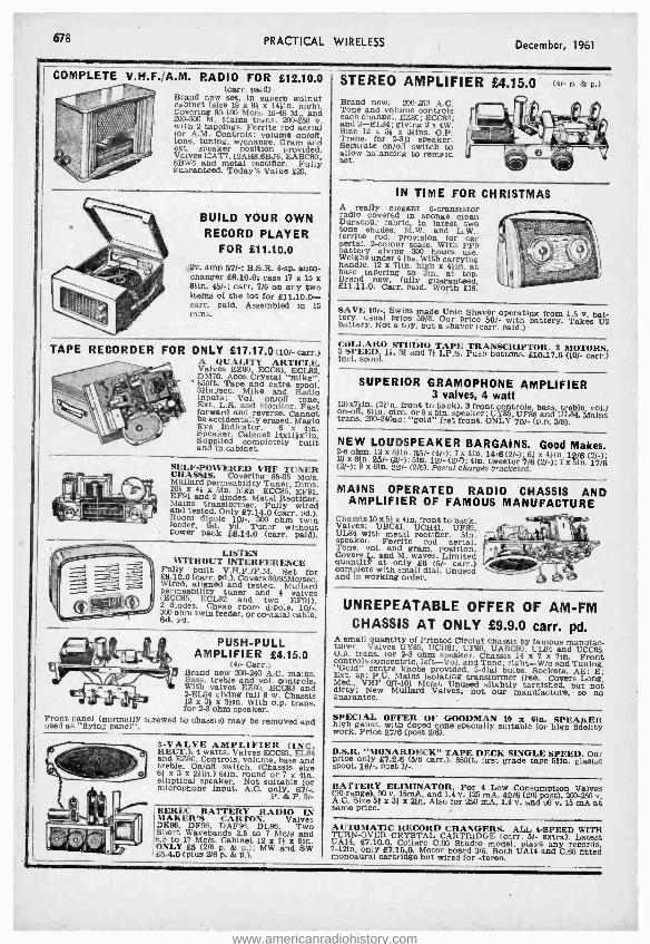
678
COMPLETE
PRACTICAL WIRELESS December, 1961
V.H.F.,A.M. RADIO FOR 812.10.0 (carr. paid)
Brand new set, In superb walnut cabinet (size 19 x 89 x 14 9in. high). Covering 80 -100 Mc /s. 1649 M., and 200-500 M. Mains trans. 200 -250 v. with 2 tappings. Ferrite rod aerial tor A.M. Controls: volume on /off, tone, tuning, w /change. Gram and ext. speaker position provided. Valves 12AT7, 12AH8,6BJ6, EABC80, 6BW6 and metal rectifier. Fully guaranteed. Today's Value £20.
BUILD YOUR OWN RECORD PLAYER
FOR £11.10.0
amp 57/ -; B.S.R. 4-sp. ante- changer £6.10.0: case 17 x 15 x 8 1ín. 45/ -; carr. 7/6 on any two items of the lot for £11.10.0 - carr. paid. Assembled in 15 rains,
TAPE RECORDER FOR ONLY £17.17.0(10/ - carr.)
ValvQUALITY O. ECC83, ARTICLE.
L8 DM70. Acos Crystal "mike ". 38It /sec, Mike
extra Radio inputs; Vol. on /off tone, Ext. L.S. and Monitor. Fast forward and reverse. Cannot
be accidentally erased. Magic Speaker. Cabinet 14x11 }x71n. Supplied completely built and in cabinet.
SELF -POWERED VHF TUNER CHASSIS. Covering 88 -95 Mc /s. Mullard permeability Cn E1, F9 EF91 and 2 diodes. Metal Rectifier. Mains transformer. Fully wired and tested. Only 27.14.0 (carr. pd.). Room dipole 10/ -. 300 ohm twin feeder, 6d. yd. Tuner without power pack 26.14.0 (carr. paid).
LISTEN WITHOUT INTERFERENCE
Fully built V.H.F. /F.M. Set for £8.12.0 (carr. M.). Covers 88/95Mc /sec. Wired, aligned and tested. Mullard (ECC85,
tuner and 4 valves 2Edi des.
ECL82 room dipole. 10 / -. 300 ohm twin feeder. or co-axial cable, 60. yd.
Front panel (normally used as "flying panel ".
PUSH -PULL AMPLIFIER £4.15.0
(4 /- Carr.) Brand new 200 -240 A.C. mains. Bass, treble and vol. controls. With valves EZ80, ECC83 and 2-EL84 giving full 8 w. Chassis 12 x 33 a 3 9fn. With o.p. trans. for 2-3 ohm speaker.
screwed to chassis) may be removed and
3 -VALVE AMPLIFIER (INC. 4W andEZ80. 4 watts. Valves ECC83, EL84 and EZ80. Controls, volume, bass and treble. On /off switch, (Chassis size 0 69 X 3 x 241n.) 69ín. round or 7 x 4ín. elliptical speaker. Not suitable for microphone input. A.C. only. 67/ -.
P. & P. 31-
BEREC BATTERY RADIO LN MAKER'S CARTON. Valves DE96, DF96, DAF96, DL96. Two Short Wavebands 2.5 to 7 Mc /s and 6.5 to 17 Mc /s. Cabinet 12 a 79 x 6in. ONLY 4S (2/6 p. & p.); MW and SW £5.4.0 (plus 2/6 p. & p.).
STEREO AMPLIFIER £4.15.0 Brand new. 200 -250 A.C. Tone and volume controls each channel. EZ80; ECC83; and 2 -EL84; giving 2 x 4W. Size 12 x 34 x 39ins. O.P. Trans. for 2-30 speaker. Seifarate on /off switch to allow balancing to remain set.
(4/- P. & p-)
IN TIME FOR CHRISTMAS A really elegant 6- transistor radio covered in sponge clean Duracour fabric, in latest two tone shades. M.W. and L.W., ferrite rod, provision for car aerial. 2- colour scale. With PP9 battery giving 300 hours use. Weighs under 4 lbs. With carrying handle. 12 x 7 1in, high x 491n. at base tapering to 21n. at top. Brand new, fully guaranteed. 211.11.0. Carr. paid. Worth £16.
SAVE 10 /.. Swiss made Unic Shaver operating from 1.5 v. bat- tery, usual price 59/8. Our price 50/- with battery. Takes U2 battery. Not a toy, but a shaver (carr. paid.)
COLLAR() S3! Dd LPg PRLCt MÓroé { and Push £10.17.8 /- c ) incl. spool.
SUPERIOR GRAMOPHONE AMPLIFIER 3 valves, 4 watt
13 }x7 }in, (24ín. front to back). 3 front controls, bass, treble, vol./ on -off. elin. cire, or 8 x Sin. speaker; UY85, ÚF86 and ÚL84. Mains trans. 200- 240ac; "gold" fret front. ONLY 70/- (P.P. 3/6).
NEW LOUDSPEAKER BARGAINS. Good Makes. 10
ohm. i 25/- (8hj; Sin. 12/ -)(2 /i) en. tweeter 7/6 (2/ -); 7 i Sin.(17 /6 (2/ -): 9 x sin. 22/- (2/6). Postal charges bracketed
MAINS OPERATED RADIO CHASSIS AND AMPLIFIER OF FAMOUS MANUFACTURE
Chassis 10 x 50 x 4in. front to back. Valves: UBC41, UCH41, ÚF89, UL84 with metal rectifier. 5in. speaker. Ferrite rod aerial. Tone, vol., and gram, position. Covers L. and M. waves. Limited quantal at only £6 (5/- carr.) complete with small dial. Unused and in working order.
UNREPEATABLE OFFER OF AM -FM CHASSIS AT ONLY £9.9.0 carr. pd.
A small quantity of Printed Circiut chassis by famous manufac- turer. Valves UY85, UCH81, UF89, UABC80, ÚL84 and UCC85. O.p. trans. for 2-3 ohm speaker. Chassis 14 x 7 x 710. Front controls concentric, left -Vol. and Tone; right -W /c and Tuning. "Gold" centre knobs provided. 2-dial bulbs. Sockets, AE; E; Ext. sp; P.U. Mains isolating transformer tree. Covers Long, Med., VHF (87 -101 Mc /s). Unused slightly tarnished, but not dirty; New Mallard Valves; not our manufacture, so no guarantee.
SPECIAL OFFER OF GOODMAN 10 x 61n. SPEAKER high gauss, with doped cone specially suitable for high fidelity work. Price 27/6 (post 2/6).
B.S.R. "MONARDECK" TAPE DECK SINGLE SPEED. Our price only £7.2.6 (5/6 carr,). 860ft. first grade tape 54ín. plastic spool. 16 / -, post 1 / -.
BATTERY ELIMINATOR. For 4 Low Consumption Valves (96 range), 90 v. 15mA, and 1.4 v. 125 mA. 42/6 (2/6 post). 200.250 v. A.C. Size 51 x 31 x 21n. Also for 250 mA, L4 v. and 90 v. 15 mA at same price.
AUTOMATIC RECORD CHANGERS. ALL 4 -SPEED WITH TURN -OVER CRYSTAL CARTRIDGE (carr. 5/- extra). Latest í1 7 Or od 3Boo A14 d fitd 7 -2n, onlyS.15.0 Moto bar 3/6.
model, an C.80 fitted monaural cartridge but wired for stereo.
www.americanradiohistory.com
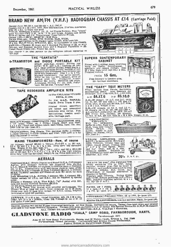
December, 1961 PRACTICAL WIRELESS 679
BRAND NEW AM /FM (V.H.F.) RADIOGRAM CHASSIS AT £14 (Carriage Paid)
4 liLà rapped input 200-225 v. and 226 -250 v. A.C. ONLY. Chassis size 15 x 81 x 54in. high. New manutacture. 12 m'ths. guarantee. Dial 14) a 4in. in black and gold. Pick -up. Extension Speaker. Ae., E., hd Dipole Sockets. Five "piano" push buttons -OFF L.W.. M.W., F.M. and Gram. Aligned and tested. With all valves and O.P. Transformer. Tone Control Fitted. Covers 1,000 -1,900 M.: 20) -500 M.; 80-98 Mc/s. Valves EZ80 rect.. ECI181, EF89. EABC80, EL84 ECC85. Speaker and Cabinet to fit chassis ( table model), 47/6 (post 3/6). 10 x O(n. ELLIPTICAL SPEAKER. 201, to purchasers of this chassis. TERMS: -(Chassis) £5 down and 5 Monthly Payments of £2, or with Cabinet and Speaker £5.10.0 down and 6 Monthly Payments of £2. Cheap Room Dipole 10, -. Feeder 8d. yard. This chassis is an ideal partner for the radiogram cabinet appearing on íh10 page
THE "CANTATA" 6- TRANSISTOR and DIODE PORTABLE KIT
400mW push -pull output; Ferrite rod aerial; M.W. and L.W. operates on two 4.5 v. cells: printed circuit. board size 81 x 2fin. with all holes drilled; booklet of full assembly and alignment Instructions: all parts sold separately. Size 9 x 31 z 71n. Mullard transistors. Car aerial socket. Write tor list: 8 z 2110. speaker, price of
cabinet (post xtra Batteries 5/6 extra.
Aiignment Service 17,- Inc. post. Fully - built Set 10 Ros. Caratage paid.
TAPE RECORDER AMPLIFIER KITS (a) For COLLARO STUDIO
DECK. 11 Rne.
(b) For B.S.R. MONAR- DECK Twin Track 8 Rms.
Printed circuit amplifiers are tested and assembled complete with valves. Full instructions. Leaflet avail- able. Carriage paid.
MINIATURISED COMPONENTS FOR TRANSISTOR SET. 3 I.F. trans. 7/1810. sq. x 9/161e.: 2 -gang 165pF plus 65pF;
z )l for put (goat output trans. each 9 /16in. cube: oso. coil.
THE
1-0044 (yTORS. p(orange Grade. andblue) ).THE LOT oí8 or 1-0044 iyellowy 3-0045 3718 (registered 11- extra).
MAINS TRANSFORMERS -New, of course (A) Primary tapped 200.250 v. Output 275-0-275 v. at 200 mA: 8.3 v. 8A and 5 v. 3 Ai 41 a 44 x 41n. Drop thrill top shrouded type. Weight 10 tbs. 361- (post 4/ -). (B) Tapped primary 110 v., 125 v.. 150 v., 210 v. and 240 v. 250-0-250
Drop thrilit' type top shrouded Weight 4) lbs. Price 22/6 (Post 3/-).
AERIALS Combined B.B.C. (Single Dipole) and Band 3 LT.A. (5- Element) Aerial, with chimney lashings and Stand -off Arm 63.15.0. I.T.A. (Band 3) Aerials, for clipping to existing mast of diameter lin, to 21n. Alternatively with wall -fixing plate at same price: 3 element 61.2.0, 5 element 61.10.0.8 element £8.10.0,11 element 63.2.6. Chimney lashings and Stand-off Arm 201- extra for each of above.
Larger aerials for I.T.A. and BB.element . Óan be suppled
element pecial
order. Double 8 Element I.T.A. Plus B.B.C. "H" Aerial with loft. pole and double chimney lashings. 68.10.0. All the above aerials are carriage paid.
Table Top . reception The
Wolsey Hi-Qt19 /6 (2/6 post). up Is. Cross-over unit in base se with) socket
for B.B.C. aerial. Slightly
PERSPEX. 15 z 12 is 1m., tinted bluelgreY. 6/6; 12) z 96 a í1n., Clear. 5 / -i 16 x 14 z 3/161ns.. Clear 7/6. Postage 2/- on 1; 3/- on 2 or more: 6 post paid.
SUPERB CONTEMPORARY CABINET
Fitted with 3 sliding doors providing room for Radio. Autochanger. 4
speakers, and record storage. Size 38 x 2410. high (plus legs sin.) x 161n. Polished walnut.
PRICE 15 Gns. Free delivery in London area.
35/- carriage elsewhere.
THE "CABY" TEST METERS Prices include Test Prods, Batteries, Instruction Book. Also measure dB. Accuracy : A.C., 3 per cent, D.C.. 2 per cent.
A -10 £4.17.6 B -20 £6.10.0 A.10-2K ohms /v. on A.C. and D.C. volts
ohms: iin , 25 mA and 250 mA. D.C. Size. 51 a 31 x 111e. Weight 17 oz. B.20 -10K ohms /v. on 0.5 v. and 2.6 v.; 4K ohms /v. on 10, 50. 250. 500 and 1000 v., A.C. and D.C. Resistance. 2K, 200K, 2M and 20M ohms: D.C. current. 100 mlcroA, 2.5 inA, 25 mA, 250 mA. Size 61 x 31 x 2í1n. Weight 24 oz.
GRAMOPHONE AMPLIFIER
With 5in. SPEAKER. Baffle 124 x 6'n. EZ40 and EL41. Tone and Volume On /Off switch. Two Knobs. Ready to play. Useful for Stereo. ONLY 571 -. post 3) -.
s-VALVE AMPLIFIER (INC. RECT.). 21 watts.ECC83. ECL82 and EZ80. Controls, volume bass and treble. On /off switch. Overall size
41 over valves. Mains and O.P. trans. and 61 s 41in. Celestion speaker. Suitable tor for microphone Input and for guitar amplifier. A.C. only.
70r- P. & P. 41-.
"READY TO USE" ITA CONVERTER Direct switching ITA to BBC, metal rectifier, co-axial plug. Can be fitted in
set. mALL AREAS. ALL SETS. your
CHANNELS. 12 months' guarantee (3 months on valves). Separate gain controls. Valves ECF80 and ECC84. Switch positions OFF -ITA- BBC. Bakelite moulded cabinet. 89 x 4 a lin. 70/- (3 /- P. & P.).
PANEL OF 7 POTS. 10 a 141n x 1M & 3 z 2M. 41/- (Post 11-). . -_ _
6 DIFFERENT PRE-SET POTS. 2K to 500K, 3/- (post 1/3).
MAINS TRANSFORMER. 6.3V í1A and 280v. 30mA. 7 / -(Post 1/6).
Send 6d. (stamps will do) for 20 page illustrated catalogue. All New Goods. Delivered by return. Terms: One -third down and balance
plus 12/6 In four equal monthly pa down Terms for A.M/F.M.Chassis ALL I MS GUARANTEED 1MONNTHS -B V A. VALVES 3
Special OTHS.
GLADSTONE RADIO "SCALA," CAMP ROAD, FARNBOROUGH, HANTS. Farnborough 3371
Also New ocoerSa Hants, d stlo Tel. Farnboroghlsdt rday Prsmouth'anBriolclsed Wednesday.
Posted Orders to Farnborough Please.
www.americanradiohistory.com

680 PRACTICAL WIRELESS December, 1961
RECTIFIERS 12 v. 31 amps, 9/6, RM1, 8/8, R512, 8 / -, EMS, 9/ -, ßM4, 15/6, REM, 211 -, 1.4A86, 171 -, 14A97, 28/., 14A100, 26 /., 16EC1.1.16 -1 7/9, 18EA1.1 -164, 7/9, 18822- 2.8-1, 14/ -, 14EA1 -2-8 -2, 17/, 14E3.1- 2-8-3, 20/., Silicone Diodes, 150 v., 500 M.A., 8/ -,
VIBRATORS -Masteradlo - 6 v. 5 Pin and 7 Pia., 8/&
NEW CARTRIDGES Power Point, 17/, Ands, ÚP65, 3U, 22/6, Sonotone by Plessey, 17 / , 25 ASSORTED MIXED Electrolytic Condensers. Many Popular sizes. List value approx. £5. Oar pm. 10/- P. & P. 2r -.
AM /FM KIT Gorla, Tuning Heart assembled, with let L.F. Transformera, A.M. and F.M. and discriminator Transformers. Complete Kit with ECC85 valve. 49/6 P. & P. 1/6.
GET 15 Latest G.E.C. High Power, Contact Cooled, manu- facturer's matched pair Transistors, with Push -pull Input and Output Transformers and Amplifier Circuit. Knock -ont price 29/- P. & P. 1/6.
SUPER STEREO KIT Kit of ready built Unite, eompnsiug 1 Midget 3 watt Amplifiers, Push Button Switch, Transformer, Control Unit, (Bass, treble and Vol). Power Pack, One Speaker (Extra Speaker 7/6), Indicator Light, Valves and Instructions. 59/6 P. & P. 31..
PM SPEAKERS E ohms, top make,
I per br .move guaranteed;
HIGHEST QUALITY- COMPARE OUR PRICES Tubes r- 1,116.G UARANTEED MOST MULLARD, MAZDA, COSSOR, EMITRON, EMI - SCOPE, BRIMAR, FERRANTI TYPES, PROCESSED IN OUR OWN FAC- TORY.
6 Months 12 Months Seconda REGUNNED
121n. £2- 0 -0 £3- 5 -0 I4in. £2 -10 -0 £3 -15 -0 15 /I7in. £3- 5 -0 £4 -10 -0 211n. £3 -15 -0 £5 -15 -0
NEW TYPES
NEW 31/74 L4 -0 -0
MW 36/24 £S -0 -0
CRM 172 MW 43/64
£6 -0 -0
S/- 7a'111/- 13/-
METERS 0.25 amp., 9/ -, 0 -300 illiamps., 12/8, 0.500 M.A., 12/6. 0 -30 M.A., 12/6. 0 -1 M.A., 26/ -, 0-50 micro - amps., 45/ -.
4 -SPD. RECORD PLAYERS Latest B.S.E. TU9 Turotabie, together with Ir;ht- weight Starr Galaxy dual sapphire crystal turnover pick -up head. Truly amazing value at Carr. 3/ -. £3.10.0 100 RESISTORS 6/6
100 CONDENSERS 10/- Mimature Cerum a and Sliver Mica Condensers, 3pF to5,500 pi,. LIST VALUE OVER a.
CO -AX standard and low lose, '25 yds., 12/8. A 50 yds., 22/8, 100 yds., 42/6. Co -ax. Plugs 1 /3. Wall outlet boxes 3/8.
UNIVERSAL VOLT OHM MULTIMETER Reads A.C. and D.C. volte to 1000. 5 ranges at 1000 ohms per volt resistance reading to 200K in 2 ranges. Complete with prods. 59/8. P. & P. 1/8.
EY51 BET 4/6 U25 SHORT 8/-
TRANSISTORS White Spot, 8/8, Red Spot, 8/, Yellow Spot, 2/8. Diodes General Purpose, Famous make 9d- each. 8/- dos.
EX -TAT Aatiference Aerials, 1311. Whip AerlaL Screened Down Leads, Matched Transformers, Mona mg Cope etc. Amazing Value 29/- P. & P. 5/,
TEST SETS TYPE 74A A service acope easily convertible for standard nee, 2001250 va.o., all valves, E.C.R.30. tube, excellent case worth £10. Our Price £4.10.0 COMPLETE RECORD PLAYERS B.S.K. VAS, 4 Speed Autochanger .. £6 15 0 B.S.R. UA14, 4 Speed Autochanger .. 17 19 0 B.S.R. UA2O, Autochanger .. .. £6 19 0 Garrard 209/210 .. .. £9 19 0 EMI 4 Speed Single Player .. 24 12 0
P. e, P. on above 4/ -.
LOUDSPEAKERS TOP MAKES -MANUFACTURER
FRESH 291m 18 / -; 31n. 18 / -; Mi, 18/ -; Sin. 16/ -; Sin. 19/ -; 10ín. 22 /8; 7 x tin, elliptical 18/ -; 0 x 61n. elliptical 22/6; 10 x bin. elliptical 23/8; 8 x 1: /in. Speakers 291,
MAINS AMPLIFIERS 3 valves (10103, 10P14, UÚ9), watt, Sip. loud- speaker, in two tone cases with controls. Ideal for record players. 19/6 P.P. 6 / -.
AUDIOTAPE 3in. Plastic 150 ft., 0 / -, 45m. 300 ft., 10 /6, 5in. 600 ft., 18/ -, 59m. 850 ft., 24/8, lin. 1,200 ft., 80/-. * VALVES BY RETURN OF POST *
THE MOST COMPREHENSIVE COMPETITIVE VALVE LIST IN THE COUNTRY
10% DISCOUNT SPECIAL IA OFFER 01 any SIX VALVES marked in Mash type (15% IA dosen). Poet: 1 valve, 6d., 2.11, 11 -.
FREE TRANSIT INSURANCE. All valves are new NEW LOW PRICES or of fully guaranteed ei- Government or ex-equip- GUARANTEED 3 MONTHS meat origin. Satisfaction or Money back Guaran-
tee on goods if returned unused within 14 days.
1A66T 6/-
1l.`óOT 11/8 88
1D5 8/8 1D6 9/9
1L4 3/6 3/6 1L05 8/8
MGT 9/9
1tli 8/- 185 4/9 114 3/9 2A3 7/9 2D21 4/8
SAS 9/. 306 4/8 SQ4 7/.
384 5/8 5/8
SRt6 9/6 5T4 8/9 6II411 4/9
5Y3G 5/9 6Y3UT 8/- 6Y441 11/- 503 8/3 504 11/- 6Z40 8/8 MGT 11/- 6A6 7/8 6A7 10/- 6A8G 9/8 6A8GT 13/. BABB 7/.
BAGS 3/6
OAKS 5Ì- 8AL5 8/8 BAMB 3/-
6AT6 5/- 6A116 7/8
6B80 8/8
6BE6 5/9 0BU6G 12/8 68116 6/- 813J6 81- 0BB7 9/3
6BW7 6%9 86X8 4/9 824 3/8
606 4j9
6CO3G 21/- OCHB 8/3 6D1 9d. OM
D3 12/6 OD6 4/9 6F1 4/3 6B66 5/9 611.6M 7/- 6F8O 8/3 61712 8/6 6F13 6/9 6F14 9/8 6F15 9/8 01,16 8/8 6F33 8/8
ÚH9 4/8
6J3GT 8%9 eJ6 4/- 627 7/9 13,17G
76T 7/8 6J3 8/8
6K7 5/9 5/9
6K7 GT 4%9 6K3UP 8/S OLl 12/8 41,6 9/9 6L6G 6/9
OL19 12%6 6103 9/. 6LD12 7/8
6N7D 8%8
8P25 14/. 88
6P28 12/6 8Q7G 6/.
lQt7UT 8/9
8SA7 5/9 651 4/9 881C7 4/8 6817 4/6 68E7 5/8 68L7GT 6/- 68N7GT 4/9 08Q7 8/- 6887 4/8 6U4GT 10/8 6(250 8/3
6V6GT 5/9
624 5/. 6X5G 5/. 0X3GT 5/6
7656 12jß 7B6 9/-
705 7/9
7117 7g 7K7 3/6 7Q7 7/8 767 9/- 7V7 8/-
704 %8 8D3 3/- 1001 11/-
10F14 5%9
10LD3 7%9 101011 13/9 101.012 8/0
10P14 9%- 10P18 7/8 12Ad 5/- 12AH7 6/9 12AH8 9/9 12ATO 7/6 12AT7 5/8 12AU7 8/- 12AX7 8/9 1.3BAO 8/. 12BE6 8/6 1213E17 10/8
12E1 18%8
1 K7GT 4%9 12E6 12/. 12K8GT11/-
1'2dU7T 8//- 12527 6/8
12S GT4/- 1225 9/8 1487 22/8 19AQ5 7/3 1913G6G15/- 2001 8/8
2ÚL1 18/8 20P1 9/9 20P3 12/8
20P5 16/-
8518G 6/9 35LdGT 9/- 25 MG 8/-
?6Z56 8/8 25E6 12/- 376U 25/- 3001 7/8 30F5 8/9 30FL1 9/6 3011 7/- 30P4 12/8 30P13 8/- 30P18 6/9 35L6GT 9/8 35W4 8/9
35Z5UT 78 43 7%8 6005 7/6 50L60T 9/-
33KU 10%8 54K1J 8/9 7gdPT 118/-
73 8%8 80 5/9 83 9/8 165BT 18/- 807(A) 5/8
808fE) 15/- 954 2/- 955 3/9
3703 1Ó/8
900.1 4/9 9003 4/- A'PP4 2/.+
881 8/6 805 4/8 CBL31 21/- CCH33 14/- CL33 11/9 CY31 7/8 063 1/8 D77 8/8 D152 5/9 DA30 12/6 DA90 2/8 DAC32 9/9
DAF96 7/8
DF91 3Ì6 01,98 7/8 01188 6/8
DK32 11/8 DE91 5/6
DK96 78 01.35 9%8 DLO2 9/- 01.91 8/. DL92 8/- 01.94 8/-
DA30 7/3 9d
EABC80 7/8 EAC91 4/6
g6s43 1jÚ
EB91 3/8 EB11Y 9/- EBC33 4/9
EBCO1 7/9 EBF80 7/9 EBF99 8/8 EBL'31 12/6 EBL31 21/. ECS2 3/6 EC90 3/8 EC91 4/8 ECM 9/6 E0032 4/- E0033 4/8 ECC34 9/-
ECC81 5/6
ECC83 8/9 E0084 7/. E0085 7/9
ECF82 8/8 1901121 12/6
ECHSE 7%9
ECL80 7/- ECL82 8/9 ECIa13 12/- EP22 7/- 6F36 8/3
EF40 13Ì8 EF41 6/- EF42 7/6 EF50-BR21-
EF50-USA S-
EF54 3/3 EF80 4/9
EF36 e/8
EF89 8/9 EF91 3/. EF92 4/8 EF95 6/6 EK32 7/- EL32 8/9 ELM 8/- EL35 7/. EL37 11/6 EL38 12/6 EL41 8/.
EL/34 7%-
ÉM 4 8%6 EM80 7/9 EM81 8/9
EM85 10%8 E5731 16/-
Small 8/-
EZ35 8/- EZ40 6/8 EZ41 7/- E.380 8/- E/.81 8/8
HL41DD7/9 HVR2 7/8 KL35 7/8
KT33C 4%9 KT38 9/-
ETU 8Ì8 KT61 8/8
KT76 8/8 KTWO1 5/9 KTW63 6/9 KTZ63 5/6 163 5/6 LN1S2 7/- L2319 7/. MU14 e/- N37 11/. N78 15/. 51108 16/- N152 8/9
P81 2%8
PCC898Ó17/. PCC85 7/3 PCC88 19/-
PCÑöO 18/8
PCF82 7/3
PC1d3 10/8
PEN35 48 PEN46 7/3
EN48 6/3 PL:4s 8/8 PL30 10/8
PI.81 18/e PL82 6/9 PL83 8/9
PM34 11%- PX25 11/8
PY32 10/9 PY80 71-
PY82 8/.
3 PY83 7/8 PZ30 8/8 RIS 11/. 1119 11/- ODO 6/g 8P8 8/8 SP41 2/8 SP61 2/6 BU216OA
4/6
TD1D4 7/8
U18 8%- U22 6/9 U24 1,5/-
U ö 9%9 U31 7/9
U37 28%-
U50 6/9 052 4/9 U76 5/6 378 5/- (2191 11/.
Ú23d 9/8
1.1309 71- (2339 7/-
12404 8%- U801 28/-
UAFalO 818
UB41 8/-
UBDK1 10/- UBF89 7/9 U131.21 14/6 UCC84 1418 UCCtlS 7/9 UCFOO 16/. UCH21 12/6 IIOH4E 7/8 UCH41 8/8 U01.88 18/8 UF41 8/6
UF80 7E
UF86 14/f UF89 7/. U141 7/.
Ú1.48 9/9 UL84 7/6
UU60 19/8
UUB 171- UY1N 11/- UY21 11/- UY41 6/- UY85 6/8 Vß105/38/8
VR160/30 6/9
W76M 15%- W81 7/6 6á,M lb/g
X65 11/-
X76M 12/- x70 22/- X79 18/8 X81 10/. 17O3 6/8 Z68 5/. Z66 9/8 Z77 e/- Z152 4/9 Z719 4/9
osti 2 lbs. 1 f6 4 lbs. 2' -, 7 lbs. 2,9, 15 lbs. 316, etc. No C.O.D.
TECHNICAL TRADING CO. ALL ITEMS 5% & POST FREE IN DOZENS (Callers always welcome) LIST OF 1000 SNIPS 6d.
P.O. BOX (21)W 350 -352 FRATTON ROAD, PORTSMOUTH.
www.americanradiohistory.com

December, 1961 PRACTICAL WIRELESS 681
STERN'S MULLARD DESIGNS Designed by 11Ui.LA RD- presented "y atuas...a strictly to spec,neatton
COMPLETE KIT OF PARTS MULLARD "5 -10" MAIN AMPLIFIER For us MULLARD to pr Which undistorrted pe output of u8 to l watts is
with
MUApvpESind LLRD VALVES, including PARMEKO MAINS TRANSFORMER and choice of the latest Ultra- Linear PARMEKO or the PARTRIDGE Output Transformer. COMPLETE KIT OF PARTS £10.0.0 (PARMEKO Output Trans.). INCORPORATING PARTRIDGE OUTPUT ASSEMBLED and TESTED. £11 .10.0 TRANSFORMER. £1.8.0 EXTRA.
MULLARD'S PRE -AMPLIFIER TONE CONTROL UNIT Ethme
MAIINVAMPLIFERS,, buti era oe per-
fectly suitable for other makes. £8,0.0
KI PRICE COMPLETE £6.6.0 ASSEMBLED AND TESTED
Supplied strictly to MULLARD'S SPECIFICATION and incorporating: Equalisation for the latest R.I.A.A. characteristics. Input for Crystal Pick -ups, and variable reluctance magnetic types. Input (a) Direct from High Imp. Tape Head. (b) From a Tape Amplifier or Pre -amplifier. Sensitive Microphone Channel. Wide range BASS and TREBLE Controls.
COMPLETE MULLARD "5 -10" AMPLIFIER The Con- trol Unnit providing up to 10 watts higgh quality ,reproduction. Only Specified Components and new MULLARD VALVES are supplied including PARMEKO MAINS TRANSFORMERS and choice of the latest PARMEKO or PARTRIDGE ULTRA- Linear Output Transformers.
PARTE £11.10.0 and TTESTEDL £13.10.0 H.P.
incorporating PARTRIDGE OUTPUT TRANS. £1.6.t extraa..
COMPLETE MULLARD "3 -3" THE IDEAL AMPLIFIER FOR A SMALL HIGH QUALITY INSTALLATION EXCELLENT REPRODUC-
TION UP TO 8 WATTS COMPLETE
KI £7100 ASSEMBLED 19.6 OF PARTS '. and TESTED (plus 8/6 carriage and insurance) H.P. Terms: Deposit £2.0.0 and 8 Months at 81.0.0. Complete to MULLARD'S SPECIFI- CATION including Mullard valves and a PARMEKO OUTPUT I TRANSFORMER.
STERN'S INTER -COMM BABY ALARM
A small versatile Unit employing the new MULLARD ECL88 valve and designed to Provide
to extreme distances. Operates conversation
mains 2)0 to 250 Volta. PRICES . MASTER UNIT
and ONE EXTENSION
KIT OF PARTS 26.17.8 ASSEMBLED AND TESTED 28. ' .8
a e 8 i ONE EX-
TENSION (a second extension may b added to any time). Master Unit incorporates switching and power supply and with the chassis completely isolated from the mains is operated in absolute safety. Cases covered in quality leatherette.
A BULK PURCHASE OF MARCONIPHONE TAPE RECORDING EQUIPMENT ENABLES US TO OFFER The Model MTR /1 PORTABLE TAPE RECORDER FOR ONLY U5.0.0 (carr.& Ins. 10 /- extra)
Deposit £8.0.0, 12 months of 81.18.8 The list price of the MTR /1 is £44/2/0. It is a 3 -Speed Twin Track Recorder incorporating the latest Collaro "Studio" Tape Deck and operates at 1l, 31 and 70n. /sea Speeds. It incorporates a "Pause" Control, a safety interlock device which ensures that a recorded tape cannot be accidentally erased and a low level output socket so that the output may be fed Into an external high fidelity amplifier for monitoring purposes or for high quality reproduction on playback.
COMBINED ORDER PRICE REDUCTIONS
(a) The RIT OF PARTS to build both the "5-10" Main Amplifier and the 2 -valve PRE -AMP CON- £15.15.0 TROL UNIT (b)
both ASSEMBLED and TESTED ILP. Dep. 13.18.0 and 12 £18.18.0 months of £1.7 8
l RECORD PLAYERS The Latest Models are in stock.
many at reduced prices. Send S.A.E. For Illustrated Leaflet.
SÌN L GERRECORD PLAY - £3 15.0 ER with separate Crystal Pick -u& Carriage and Insurance 5/- Above Pick -up separately for 11.6.6 The NEW COLLARO MODEL R
S4 4 -speed Single Record £9 Player. Studio Cartridge. The NEW COLLARO C80 4 -speed Autochanger unit with £7.19.6 Studio "O" Pick -up
Record Player with crys al Pickingle£6.9.6 up B.S.R.
Autochangeruwiith £7.10.0 Crystal Pick -up Available Incorporating the B.S.R. STEREO Pick -up, plays £813.10 L.P. and 78 Records. GARRARD MODEL TA/MBII 4-
s speed Player fitted .10.0 GARRARD Auto- changer 4-speeds. gh £10.10.0 output. Crystal Pck -up
Carriage and Insurance on each above 5/- extra. -
SPECIAL CASH OFFER
This very attractive PORTABLE AM- PLIFIER CASE together with a good quality and a machdP.M. SPEAKER. ALL for ONLY £8.7.6 (Plus 7/6 Ìar . The Amplifier consists of a 2 -stage de- sign incorporating 3 modern B.V.A. valves and has separate BASS and TREBLE CONTROLS
dilate Portable
ost any make of Autochanger and is WE ALSO SUPPLY
finished EPARATELYhoom
Grey Reztae.
(a) The 2 -stage (plus Rectifier) AMPLIFIER 24.2.6
(b) The PORTABLE CARRYING CASE £3.17.6 (c) 8lln. P.M. SPEAKER 18 /9 Carriage and Insurance 4/- extra.
MULLARD FOUR CHANNEL MIXER UNIT Self powered with Cathode f
follower output. Intorporater Two inputs for MICROPHONES One for CRYSTAL PICK UP and a fourth for RADIO or TAPE Complete Kit of Parts Assembled and Tested 218.8.8
TERMS: Deposit £2 and 12 months at 15 /-. MODEL I.L. one microphone Input matched for moving coil of
!Ribbon Mike. £1.17.0 extra. _ WE CAN ALSO SUPPLY
The MTR /1 Amplifier and Loudspeaker With the on atopP board. TESTED AND AANND all READY
8á.äaí22 USE. (Carr.
21.9.4. .' 30 1- extra). £19.19.0
STERN RADIO LTD. Dept. P.W. 109 FLEET ST., LONDON, E.C.4
Telephone: FLEET STREET 5812 3 4
r www.americanradiohistory.com
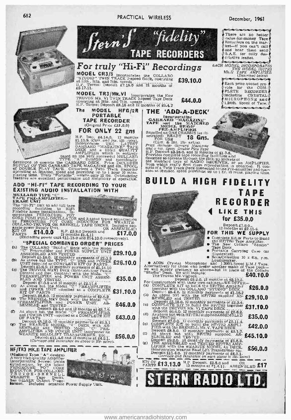
682 PRACTICAL WIRELESS
`fidelity ". Je'n'f TAPE RECORDERS
For truly " Hi -Fi" Recordings MODEL CR3 /S Incorporates the COLLARD "STUDIO" TWIN TRACK 3 -speed Deck, operating £39.10.0 at 1Hn., 3lin. and 7 }in, speeds H.P. Terns: Deposit £7.18.0 and 12 months of 82.17.11.
MODEL TR3 /Mk.VI Incorporates the New TRUVOX Mk. VI TWIN TRACK 2 -speed Tape Deck operating at 31in. and liin. speeds H.P. Terms: Deposit £8.18 and 12 months of 83.4.7 The MODEL HFG /2R
PORTABLE TAPE RECORDER (Original Price L33.0.0)
FOR ONLY 22 gns H.P. Dep. 84.14.0. 12 months 81.13.9. (Carr. and Ins. 10 /- extra). Incorporates THE LATEST GARRARD "MAGAZINE" TAPE DECK and a HIGH QUALITY AMPLIFIER which is entirely
based on the very successful MULLARD TYPE "A" DESIGN and specifically
developed to operate the GARRARD DECK. Price INCLUDES SUPPLY OF THE GARRARD TAPE MAGAZINE and 4in. SPOOL of DOUBLE PLAY TAPE. Comprises a Twin Track Recorder operating at alin/sec. speed and providing up to 1 hour 10 mins. playing time. Truly "Portable ". weighs only 22 lbs. Outstanding features are excellent performance and simplicity of operation. ADD "HI -FI" TAPE RECORDING TO YOUR EXISTING AUDIO INSTALLATION WITH MULLARD TYPE "C"
PRE- AMPLIFIER- ERASE UNIT The "Hi -Fi" link to add full tape recording facilities to High Fidelity home installations. In- corporates FEROXCUBE POT CORE PUSH PULL OSCILLATOR and 3-speed treble equalisation by FEROXCUBE POT CORE INDUCTOR FOR WEARITE- COLLARO- TRUVOX OR BRENELL TAPE DECKS. Includes sep- arate power Supply Unit. OR ASSEMBLED KIT OF £14.0.0 H.P. £3.8.0 Deposit and £17.0.0 PARTS 12 months £1.4.11 (Excluding power unit £11.15.0 and £14.10.0 respectively).
£44.0.0
THE 'ADD-A-DECK' !nee rporat ing
GARRARD -MAGAZINE" TAPE and the MATCHED
MODEL HF /G2P PRE -AM PLIFIER
Supplied on ONE CHASSIS (as ill- ustrated) O USEADY 18 Gns.
(Carr. & Ins. 10/- extra). Price includes Garrard Magazine and a 4m. Spool Double Play Tape H.P. Deposit £3.18.0, and 12 months of 81.7.8. Provides complete tape recording facilities and the sttaandard
operate through °RADIO RECEIVsockets or an AMPLIFIER, from which really first class reproduction is obtained. It con- sists of a Twin Track Deck connected to the Pre -amplifier and oper- ates at 3ftn /sec. speed providing up to 1 hr. 10 mins. playing time.
December, 1961
There are no better value- for -money Tape Recorders on the mar - ket if you can't call and hear them send S.A.E. for fully des- criptive leaflet.
EACH MODEL INCORPORATES THE MODEL HF!TR3
Mk.II TAPE AMPLIFIER (Described below)
Each price quoted pro- vide for the COM- PLETE RECORDER including CRYSTAL MICROPHONE and 1,200ft. Spool of Tape.
BUILD A HIGH FIDELITY
"SPECIAL COMBINED ORDER" PRICES (a) The COLLARD "Studio" Deck with the Model
ASSEMBLEDiflAND TESTEDER SUPPLY UNIT £29.10.0
Deposit £5.18.0. 12 monthly payments of £2.3.3 (b) As above but the TYPE "C" Unit and POWER £x6.10.0 UNIT supplied as COMPLETE KIT OF PARTS Deposit £5.8.0. 12 monthly payments of 81.18.10 (a) The TAUVOX MkVI Deck (incorporating Pause Control and Rev. Counter) with the Model "C" PREAMPLIFIER and BLED AND TESTED
POWER UNIT ASSEM- ,+35.0.0 Deposit £7.0.0 and 12 months at £2.11.4 (d) As above but the Model "C" PREAMPLIFIER
KIT OF R UNIT supplied as a COMPLETE £31 .10.0
(e) The Deposit
R28.8.0. kV Deck with the Modell "C" LELI ad TESTED
POWER UNIT. AS- SEMBLED £46.0.0 Deposit £9.4.0 and 12 months at 83.7.8. (I) As above but the Model "C" PREAMPLIFIER
and POWER UNIT supplied as a COMPLETE KIT OF PARTS Deposit £8.12.0. 12 monthly payments of 83.3.1
(g) The WERITE MODEL "4" DECK with AS- SEMBLED and TESTED Model "C" PRE- AMPLIFIER AND POWER UNIT incorporating WERITE HEADLIFT TRANSFORMER, Etc..- £56.0.0 Deposit 811.4.0 and 12 months at £4.2.1. (Carriage and Insurance on above is 10 /- extra).
£43.0.0
HF /TR3 MK.II TAPE AMPLIFIER (Mallard Type "A" design)
05. A very high quality Amplifier incorporating 3 -speed treble equalisation. by the latest FEROXCUBE POT CORE INDUCTOR. FOR COLLARO- TRUVOX- B RENELL WEARITE Tape Decks, has GILSEN Output Trans- former. Includes separate Power Supply Unit.
ti
TAPE RECORDER
4 LIKE THIS for £35.0.0 Deposit 87.0.0.,
12 months at £2.11.4. FOR THIS WE SUPPLY
Complete Kit of Parts to Build the HF /TR3 Tape Amplifier. The New Collaro "Studio" Tape Deck. Portable Carrying Case (as illustrated). Rola /Celestion 10 x 61n. p.m. Loudspeaker.
ACOS Crystal Microphone and 1,200ft.Spool E.M .1 Tape. Alternatively for those who prefer another make of Tape Deck - we will supply precisely as above -but in place of the Collaro "Studio" oVII include: £40.10.0 Th Truvox Mk. Dec Deposit £8.2.0, 12 months at £2.19.5 For Constructors with their own cabinet -WE OFFER - (a) COMPLETE KIT to build the HF /TR3 Amplifier £26.0.0 together with the COLLARD "STUDIO" DECK Deposit £5.4.0. 12 monthly payments of 81.18.2 (b) As above but
with the HF /TR3 supplied AS- £29.10.0
Deposit £5.18.0. 12 monthly payments of £2.3.4. (c)
COMPLETE TRUVÓ Mk. i
the DECK
together £31 .10.0 Deposit £8.8.0. 12 monthly payments of £2.8.2.
(d) As T above
but with HF /TR3 supplledASSEMBLED £35.0.0
Deposit 27.0.0. 12 monthly payments of 82.11.4. (o) COMPLETE KIT to build the HF /TR3 AMPLI- £42.0.0 FIER with the BRENELL Mk. V. TAPE DECK
(f) As above and
monthly 1TEth HF
/TR3 of
msupplied, £45.10.0 but Deposit 89.2.0. 12 monthly payments of 23.8.9. (g) THE ASSEMBLED and TESTED HF /TR3 AMP- LIFIER with the WERITE MODEL 4A DECK. £56.0.0 incorporates Wearite Head Lift Transformer etc. Deposit 811.4.0. 12 monthly payments of £4.2.1. Carriage and Insurance on each above is 10 /- extra)
KIT PARDTF £13.13.0 Hlp mDntls=tar£31ß4 Ilnd AtiRF..Mßi,Fn £17
STERN RADIO LTD.
www.americanradiohistory.com
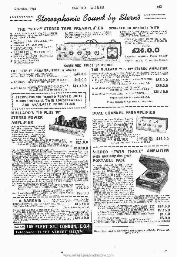
December, 1961 PRACTICAL WIRELESS 683
s Sawa /xi, stei.4 THE "STP -1" STEREO TAPE PREAMPLIFIER DESIGNED TO OPERATE WITH
COLooLAIO "STUDIO" TAPE DECK
REUrppTERatTAAPE tHEADS. latest 4 -TRACK
OVERALL SIZE CASE 131 x 3in. FRONT PANEL (Choice of Black Or White) 19 x 31ín.
PRICE
TRUVOXMkVI TAPE' DECK incorporating the latest 4-TRACK MINI - FLUX TAPE HEADS.
PUSHPf PULL OSCILLATOR
4 -SPEED EQUALISATION FERROXCUBE OSCILLATOR TRANSFORMER SENSITIVE METER FOR SIGNAL LEVEL
IN CAHTCONTROLS CHANNEL MULLARD VALVES INCORPORATED
BRENELL MkV TAPE DECK incorporating similar 4 -TRACK MINI - FLUX TAPE HEADS.
THE "STP -1" PREAMPLIFIER IS
WITH TAPE DECKS AS FOLLOWS: TRUVOX MkVI 4 -TRACK MODEL
f26O.O Including separate Power Supply Unit. Deposit £5.4.0, 12 months £1.18.2.
COMBINED PR CE SCHEDULE
offered THE MULLARD "10+10" STEREO AMPLIFIER
£45.0.0
£65.0.0 Deposit £8.0.0, 12 months £3.8.0. BRENELL MkV 4 -TRACK MODEL
Deposit £13.0.0 12 months £415.4. COLLABO "STUDIO" O 1CsDet 6 2month£3.0.11.
£41.10.0
STEREOPHONIC RECORD PLAYER UNITS
MICROPHONES & TWIN LOUDSPEAKERS ARE AVAILABLE FROM STOCK
MULLARD'S "10 PLUS 10" STEREO POWER AMPLIFIER A high fidelity design based on the famous Mallard "5 -10 ". Provides up to 10 watts (per channel) Superb reproduction. Frequency response Ilat to within 3 db from c),.. TO 00 Ke)s at 50 Mw. 'total Ilarmonie Distortion at 10 watts 0.1 %. (a) ASSEMBLED COMPLETE AMPLIFIER. in-
cluding CONTROL UNIT 24N4Ó,(12 months of 11.10.10
(b) A complete KIT of PARTS for
pp
£18.10.0
t Built
ULLARD Shspecification. Incorporates Mullard e valve line -up including
channel. Two specially designed GILSON OUTPUT TRANSFOR- MERS with 20% taps are used for ultra linear operation.
The matching CONTROL UNIT is designed to be either attached to the Amplifier (as Illustrated) or can be detached for separate mounting on a Cabinet panel. Provides inputs for CRYSTAL PICK UPS, RADIO TUNING UNIT, and also for replaying from our STEREO TAPE PREAMPLIFIER (Briefly mentioned opposite).
AS AUDIO SPECIALISTS WE CONFIDENTLY RECOMMEND THIS DESIGN it is a MUST to the serious minded sound enthusiast.
We can also supply the assembled MAIN AMPLIFIER only (ex- cludes Control unit) for operation with our DUAL CHANNEL PREAMPLIFIER, this provides for a more versatile or elaborate installation and would be essential if a low output Magnetic Pick Up. such as the Decca, is to be used. (a) THE ASSEMBLED MAIN AMPLIFIER with the PRICE:
AA ASSEMBLED DUAL CHANNEL PREAMPLI- £.30.0.0 Deposit 26.0.0 12 months of 22.4.0.
(b) A complete KIT of PARTS for both Units will be £26.0.0 available in October for
l'ItICI?: £21.0.0
1 1 A BARGAIN NEare and FULLY offer
UARAN- TEED-TRU VOX MK. VI TAPE DECKS. £18.18.0 List Price 226.5.0 for
(Carr. & Ina. 7/6 extra) Deposit 23.16.0 and 12 months at 21.7.8. A twin track model operating on 31 and Min./sec. speeds and in- corporating pause Control and Rev. Counter. THE ABOVE IN- CORPORATING THE LATEST 4 -TRACK MINIFLUX HEADS FOR
(Carr. 8 months STEREO OPERATION IS AVAILABLE FOR ,ÿ`Q1.1 O.0 21.11.7.
Dept. P.W. 109 FLEET ST., LONDON, E.C.4
Telephone: FLEET STREET 5812/314
(described below) with the "STP -1" PREAMPLIFIER and one of the TAPE DECKS provide a COMPLETE STEREOPHONIC INSTALLATION. WE OFFER
10 +10" AMPLIFIER, "STP -1" PREAMPLIFIER and the TRUVOX MK. VI DECK
Deposit 213.0.0. 12 months £4.15.4.
As above with eport 217.0.0.. 12 months 20.4.8.
As above with COLLABO "STUDIO" DECK
Deposit 212.0.0. 12 months £4.10.2.
Please enclose S.A.E. with all enquiries.
£65.0.0
£85.0.0
£61.10.0
DUAL CHANNEL PREAMPLIFIER
Incorporates two Mullard 2 -valve
Single combined
be used for both STEREOPIONIC or MONAURAL operation ,-It is de- signed primarily to operate with our range of MULLARD MAIN AMPLIFIERS but will also oper- ate fiers raegquiriwell an input of 250e
of .i
COMPLETE KIT £12.10.0 ASSEMBLED E OF PARTS
H.P. 23 Dep. and 12 irate. at 21.2.0 £15.0.0
STEREO "TWIN THREE" AMPLIFIER with specially designed PORTABLE CASE A most compact portable design consisting of TWIN CHANNEL
n designl
FIE MULLARD
tLhTe In-
corporating top grade Output Transformers, and the new audio Triode- Pentode Valves Mullard E.C.L.86. Separate Bass and Treble controls. Suitable for use with Crystal Pick Ups, and capable of genuine high quality reproduction up to 3 Watts per channel. An attractive and contemporary por- table Case in two tone colours. he unique feature of the design is the loudspeaker mounting. Two 8 x 5in. p.m. elliptical loudspeakers are separately baffled and mounted in the lid, which is detachable, allowing for each speaker to be individually which can be versatile
ssembled in the arrangement
imum of time.
£14.0.0 PRICE for the ASSEMBLED AMPLIFIER, Two B x 5in. ROLA SPEAKERS and PORTABLE CASE
Deposit 22.16.0, 12 months of 21.0.6. £7.15.0 ASSEMBLED AMPLIFIER supplied for
£1.1.0 8 x 5in. ROLA LOUDSPEAKERS (3 ohms) each
PORTABLE CASE £5.0.0 A CHOICE OF SINGLE RECORD PLAYERS and AUTOCHANGERS Is available from Stock (Send S.A.E. for details)
Illustrated and Descriptive Brochures available. Please err close S.A.E.
AA
www.americanradiohistory.com
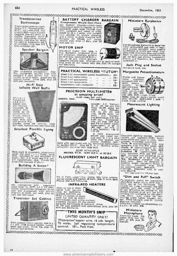
684 PRACTICAL WIRELESS December, 1961
erloc iocio ocloloclo ioocoitzloo : curio toloco ;íc oociotno cl0000ci } cici ooco;ocg 0 0 Transistorised I BATTERY CHARGER BARGAIN Miniature Earphones Stethoscope " Components Would Cost More
Car Battery Charger- ready -made U Trace signal right through: high output battery charger in stove Radio, T.V Tape amplifier, _,_ ° enamelled sheet steel louvred case. HI -Fl, etc. -simplest way i New complete and ready to work. 0 to fault -find -carry it like Rated at 12 v. 5 amps. and variable o
fountain pen -all parts in- rate selector for trickle charging, eluding transistor barrel i also a meter to show charging rate. O crystal, everything except Suitable for 230/250 A.C. mains. battery, 12/6 plus 1/6. data Special snip price of 65/ -, plus 3/6 O included or separately 1/6. post and ins. O Or complete with deaf aid ForTransistor Circuits Or Deaf Aid O type earphone, 20/-. MOTOR SNIP N 1 P Very lightweight and easy to wear, 0 O
"., cord almost invisible, good quality Speaker g , Bargain Miniature motor 2 ;in long x $ production of music and voice, eom-
,,. akin, diameter, laminated poles sü 0 Plate with miniature plug and socket, O and armature, separate winding ready to use -correct impedance OK for reversing.
mains off 20.30 v, for red spot and similar transistors. D.C. or off A.C. mains through Crystal and Magnetic. 9/ - Post and / steildown transformer. Original cost at least 23 each. Insurance 1 / -.
f, and assurance. one month only 8/8, plus 1/6 postage Jack Plug and Socket O ' ' Miniature type, 3/6. 0 0 121n. Hi- fidelity loudspeaker. High Morganite Potentiometers O flux, permanent magnet type with O standard 3 ohm speech coil. Will Single and 2-gang handle up to 12 watts. Brand new by 0 famous maker. Price 32/6. Plus 3/8 types available.
standard size with 0 post and insurance. good length
O Hi -Fi Snip spindle, all
0 Infinite Wall Baffle new and types.
- Single types, 1/-
O PRECISION MULTI -METER each, values 10K, 25K,
S at amazing price! 50K, 100K, 250K, 1 meg 2meg. 111,000 ohms per volt: Gang type 3/- each - values avail- N'1 c e 1 y ? MODEL 20011. Volt- ohm- Mllliameter able: 5Kt5K, 100K±100K 1 meg. ± Veneered f I Meg. 2 meg. t 2 meg. O and pol-
lished. Cor- I Ranges: A.C. Voltage: Fluorescent Lighting 0 net- fitting 10, 50, 100 500 and 1
O (attaches to volts (10,)00 ohms per O picture rail), volt), D.C. Voltage: Takes up no , : °3 5-25, 50 250, 500, and O floorspace. 2.5k. (20.000 ohms per O Gives really 05a Current: O fantastic re-
volt). D.C.
0 -250 mA. Resistance: O suits with only O
Capacitance: 10 pF to
low- priced Bin. - - -. ,:. . - 0-6k. 0-6 meg. (300 ohm speaker fitted for tweeter. Only $ 1 and 30k at centre scale). 45 / -each, carriage and Insurance 3/8
pf 001 mid. 001 mid, to Smallest Possible 2-gang +22
mid _Decibels: -20 to
0 O 0 0 0 0 O
0 cased. belse only trimmers,
x 7/1. polystyrene r
O le
matth. 2LSmallest -.1P PI input and P.P. out- 0 put transformers. 12/6. Circuit dia- gram free with any of above.
O Building A Scope? O 0 0 0 0 0 0. 3In. oscilloscope tube. American 0 made type No. 311'7, 6.3 v. 0.6 amp. O heater, electrostatic deflection, brand new and guaranteed with circuit O diagram of scope. 15 /- each, plus 1/6
0 post and insurance,
8 Transistor Set Cabinet
PRACTICAL WIRELESS "TUTOR', Stage 1 all components except headphones.. 20/- Stage 2 all components . .. ,. .. 15/- Stage 3 all components .. . .. .. 19/- Stage 4 all components ,. 9/- Headphones, high resistance ., .. .. 15 /-
O O O 0 0 0 0 0 O
A fully guaranteed pocket size meter (ac- tual size: 41 x 31 x lin.) knife edge pointer, top quality supplied com- plete with test prods and full operating instructions at £6.19.6 ONLY. Plus 2/6 P. & P. Optional extra, attractive carrying case 13/6 only.
ALSO AVAILABLE MODEL TE.10. 10,000 O.P.V. at £5.19.6.
FLUORESCENT LIGHT BARGAIN
Kit of Parts comprising: choke, two lamp holders, starter holder and starter, 40 watt, 19/6:80 watt. 23/8. Plus 2/- post and insurance.
INFRA -RED HEATERS Make up one of these latest type heaters ideal for bathroom, kitchen, bedroom, etc. They are simple to make from our easy to follow instructions -uses silica enclosed elements designed for the correct infra -red wavelength (3 microns), Price for 750 watt element and instructions 15/6, plus 2/6 post and insurance.
THIS MONTH'S SNIP LIMITED QUANTITY ONLY!
Waterproof heater wire. 16 yds. length. 0 Very modern cream cabinet, size 51 x 170 watts. Self regulating temperature 0 3 x Din. with chrome handle, tuning control. 10 / -., Post Free. knob and scale. Price 7/6, Plus 1/6 postage and packing, v' ttrí ,0c 0000000000000004 00000c {}0?{?4<} 00000 0000 }{;x.00 000}}4000000000
Complete lighting fittings, Built -in ballast and starters -stove enam gilled white and ready to work. Ideal kitchen, workshop- anywhere. Twin 20 approximately 27in. long complete approximately Oft. long complete with one 40W tube, 39/6. Inductor 80 approximately 5ft. long complete with one 80W tube, 49/6. Carriage and insurance up to 150 miles 7/6, up to 250 miles 8 /6. 21ín, Miniature complete with 13 watt tube. Ideal for showcase or
required. whCompleteatuwitfitting laest Ciircular Complete with 40 watt tube, £4.19.8.
Carriage and ins. 7/6 any type. "Dim and Full" Switch
Particularly useful for controlling h fiiffw bilaeonhs rt life at lamps
brilliance. switch has three positions: the first at a half brilliance for setting up, the second position is off and the third position full brilliance for the opera- tion shots. Also useful for con- trolling night ceei3
/9 each posheaters, ircuit diagram Included.
Ditto but without the off position, i.e. d.p.d.t. 10 amp. 2/9.
Miniature Microphone
American made. Dy- namic type, real bar- gain at 2/6, plus ed. postage.
A
www.americanradiohistory.com

December, 1961 PRACTICAL WIRELESS 685
0000 0000 00000 0000 00000000000000 00eß 0OCHDOICEDOOCIDOCirDOC300 21
POCKET LOUDSPEAKER TRANSISTOR RADIOS ! SUB -MINIATURE COMPONENTS
1. Ferrite aerial with Long and Medium Wave Coils, 411n. long, for pocket superhet, complete with circuit showing component values, etc.. 7/6.
2. Ferrite aerial, as above, but lin. diameter, BIn. long, for table model receiver or portable. 10/6.
3. Three I.F. 'transformers with oscillator coil and circuit details to work with item 1. 19/6.
4. Three I.F. Coils and oscillator to work with item 2. 23/6.
5. Smallest possible electrolytics. 1MFD, 2MFD, 4MFD, 6MFD, WED, 10MFD, 20MFD, 30MFD 50MFD. 100MFD, 200MFD, all 1/9 each.
6. Smallest f watt resistors, all 10 per cent values. 5d. each.
7. Miniature condensers, .1, 11 -: .05, .04, .02. .01, all Bd. values, below this 7d.
8. Miniature slide switch double pole change over. 2/6.
9. Edgewise volume controls. 2K. 5K, 10K and 20K. 2/6 each.
LO. Small edgewise controls with switch, 2K. 5K, 10K and 20K, 4/9 each.
11. Red Spot Transistors, tested and suitable all A.F. applications. 2/8.
12. White Spot Transistors tested 4 and suitable as LF. or mixer. 3/6.
13. Set of six Millard transistors for superhet Mullards in original packets, fully guaranteed, comp- rising 0044, 0045. OC81D and matched pair 0081. 82 the set.
14. Special 500 euh -miniature diodes, 1/- each.
15. Surface Barrier transistors, 5 -10 Mc /s, 6/6 each: 10-15 Mc /s, 8/- each: 20-30 Mc /s, 9/- each: 40 -50 Mc /s, 15 /- each.
16. Push -Pull Driver and Push -Pull output transformers for pocket superhets, 150 mW, 10/6 pair: 400 mW. 15 /- pair: 750 mW (driver only. no output needed). 8 /6, all complete with circuit details.
17. Smallest Tuning Condenser, size approx. lin. sq., 165pF and 65pF, with trimmers. 17/6 each.
18. Oscillator coil to suit the above, 6 /-.
19. Three I.1's, 455 k/c sub -miniature to suit items 17 and 18, 18/- the set.
20. Jackson 00 2 -gang tuning con- densers, 20813F plus 1760M, fin. spindle tapped 6BA with trimmers. 10 /6, less trimmers 9/6.
21. Tuning condensers for items 1
and 3, 9/6. 22. Tuning condensers for items 2
and 4. 10/8. 23. Printed circuit for items 1 and
3, 6 /6. 24. Printed circuit for items 2 and
4, 7/6. 1
25. 2 }in. speaker, 3 ohm. 19/6; 80 ohm, 19/6.
26. 3in. speaker, 3 ohm. 18/6: 80 ohm. 18/6.
27, 51n, speaker, 3 ohm, 18 /6: 35 ohm Hi flux. 19/6: 35 ohm Super Hi flux. 22/8.
28. Elliptical speaker,? x 4. 3 ohm, 19/6: 35 ohm. 19/8.
29. Battery connectors, large. 1/- pair: miniature. 1f- pair.
THE "PIMPERNEL" You'll hear it here . . .
You'll hear it there . . .
You'll hear our "Pimpernel" everywhere ! !
FULLS' ASSEMBLED dN5O.O
Our amazing pocket size transistor set uses five transistors and is an all British product. There is noth- ing on the market to compare with it and it is many times better than any Japanese set at simlllar price. It is a complete ready -to -work Radio. Uses only the best and latest components including 3in. Moving Coil Speaker, air spaced tuning condenser, two -tone cabi- net, etc.
SEVEN DAYS' FREE TRIAL Send today. You can keep the set for seven days and if you are not 100 per cent satisfied return it and your cash will be refunded in full.
Post and Ins. 2/8.
Demonstrations at all branches.
THE POCKET "4"
o
Circuit comprises 2 HF transistors reflexed to equal Q 4 stages. Permanent germanium diode and high gain O AF output stage, fitted with miniature speaker, proper tuning condenser, volume control and in case
O wi th handles as illustrated(less monogram), completely portable. No aerial or earth required. Pocket 4 uses 3 transistors and 1 diode, price 42/6. plus 2/6 post 0 and insurance. Pocket 5 uses 4 transistors and 1 0 diode and has feedback control, price 55/ -, plus 2/6 0 post and insurance. Prices are for medium wave models, long or medium versions 8/6 extra. GOOD RESULTS EVERYWHERE
Nothing can be more disappolnting'than to find that 0 despite care in making up, your radio lust will not O work or needs a long high aerial and water pipe earth. O We can prove good results In all areas and we guarantee O all components for 12 months. Hundreds of testi- monials received. Send in confidence. Plans tree with O parts, or separately 3J6. Demonstrations at all 0 branches.
O
NOW THE "GOOD COMPANION CAR RADIO
AND PORTABLE Largely due to the helpful criticisms
and suggestions received from purchasers of our previous set "The Real Companion" we have improved and now supersede this with a new set which we call "The Good Companion ". We feel confident that this new set is one of the finest of its kind available. The design is the combined efforts of our technicians and of those of several of the leading manufacturers in the country, and the resulting set has a performance as good as if not superior to those selling at £20 and more. It has the eight transistor set performance.
Features include American Philco R.F. transistors and Mullard A.F. transistors- Q.P.P. output giving 750 mW -full coverage ors Medium and Long - very fine tuning arrangement -excellent reception of difficult stations like 208 -variable feed -back control -full tonal qualities -really superior looking cabinet size I I x8 x 3in. approximately -or aerial attachment- several months' operation from battery costing only 3/6.
Circuit employs six transistors and two diodes, it incorporates all latest refinements, and oscillator I.F. Transformers are pre -aligned so no instruments are necessary. Anyone who can solder competently can make this set. The instructions are fully comprehensive with plenty of illustrations. Service is available in the unlikely event of your getting into difficulties. All
components fully guaranteed. Price of all components and cabinet to make set as
illustrated £9.19.6. Post and insurance 51 -. Battery 3/6 extra.
CI s 8 l.
A _ternative Cabinet available if required.
ELECTRONIC PRECISION EQUIPMENT LTD.
8 O O
80
80
O O O
8 80 O
80 O 0 O O o
post orders are dealt with from Eastbourne, so for prompt attention please post your orders to 66 Grove Road, gi
Eastbourne, marked Department 7. Callers may use any one of the Companies below. O 266 London Road. 29 Stroud Green Rd., 620 High Street North 42-46 Windmill Hill, 246 High Streçet,
0 Croydon. Finsbury Park. N.4. , Manor Park, E.12. Ruislip. Middx. Harlesden, N.W.10. Phone: CRO 6558 Phone: ARChway 1049 Phone: ILFord 1011 Phone: 0UIsltp 5780 Phone:ELGar 4444 O
Half day Wednesday Half day Thursday Half day Thursday " Half day Wednesday Half day Thursday 6 ` 00000044OOOf}OO: OOO540040004 0000004000000000000 oo0000OoOQOOO00000O
www.americanradiohistory.com
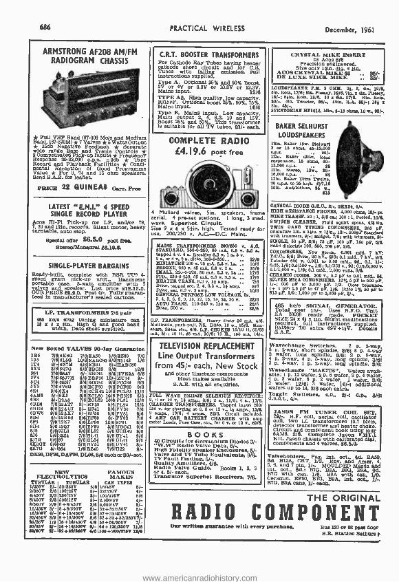
686 PRACTICAL WIRELESS December, 1961
ARMSTRONG AF208 AM /FM RADIOGRAM CHASSIS
Full VHF Band (87 -108 Mo /s and Medium Band, 187 -570M) * 7 Valves *5 Watts Output * 15db Negative Feedback * Separate wide range Bass and Treble Controls * 2 Compensated Pick -up Inputs *Frequency Response 30- 22,000 c.pe. t2db * Tape Record and Playback Facilities * Conti- nental Reception of Good Programme Value * For 3 76 and 15 ohm speakers. Send S.A.E. for leaflet.
PRICE 22 GUINEAS cam Free
LATEST a E.M.I." 4 SPEED SINGLE RECORD PLAYER
Acos Hi -Fi Pick -up for LP, and/or 78, 7. 10 and 12in. records. Silent motor, heavy turntable, auto stop.
Special offer 26.5.O post free. Stereo/Monaural 20.19.6.
SINGLE -PLAYER BARGAINS Ready -built, complete with BSR TU9 4- speed gram pick -up unit.. Handsome portable case. 3-watt amplifier with 2 valves and speaker. List price 812.12.0. OUR PRICE 29.9.0. Poet 4/ -. Fully guaran- teed in manufacturer's sealed cartons.
LF. TRANSFORMERS 7/8 pair 486_ k0/s slug t miniature can 13
width. Dattagsh L upplied. band
New Boxed VALVES 90-day Guarantee 185 7/6 6S80 7/8 EA60 1/6 EZ80 7/6 185 7/8 SLOG 10/6 EAB080 8/6 E1148 1/8 1T4 8/- 6N7M 8/6 EB91 9/I- RAB080 2%2 3/8 8Q70 8/8 ESOSI 8/6 12/e 384 7/8 88A7 8/- EBC41 8/8 HV$2A 8/6 3V4 7/8 OATHS 8/8 EB1,80 10/- MU14 9/- 504 7/8 0857 8/8 ECC84 9/6 P0084 9/8 6Y3 7/8 8V60 8/8 RCM 9/8 POF80 9/8 6Z4 9/8 81E4 7/8 ECH42 10/8 P01.82 11/8 6AM6 5/- 8X6 8/8 ECL80 10/8 PEN25 8/8 6B8 6/- 12A8 7/8 ECL82 10/8 PL81 12/6 BBEB 7/8 12AT7 8/- EF39 6/8 P1.82 10/8 BBHB 9/8 12AU7 8/- EF41 9/6 PY80 7/6 8BW8 9/812AX7 8/-RF50 5/8PY81 9/6 CM 8/- 128118 8/8 EF80 8/- PY82 7/8 BFB 7/8 12K7 8/8 EF88 12/8 81.81 8/8 e86 8/8 12Q7 8/6 EF92 5/6 UBC41 9/8 6.15 6/8 35L8 9/8 E1,32 5/8 001142 9/8 818 5/8 357.4 7/6 EL41 9/8 0F41 9/8 6.170 8/6 80 9/6 E1,84 8/8 131.41 9/8 eS80T 8/8807 6/6 EY51 9/8 UY41 8/- 6ñ7G 5/- 964 1/8 EE40 7/8 022 8/- DS98, DF9E, DAF98, DLBB, 8/8 each or 30/- Bet.
NEW FAMOUS ELECTROLYTICS MAKES
TUBULAR TUBULAR CAN TYPES 1/360V 2/- 20 /350V 5/8 18 /45V ó/- 21350V 2/3 100/25V 8/- 32)350V 4/- 4/450V 2/3 200/22V 3/- 100 /270V 6/8 8/450V 2/8 600 /12V 3/- 2,000 /6V 4/- 8 /2ó0V 2/9 8+8/450V 3/8 5,000/6V á/- 16/450V 3/- 8 +8 /500V 3/- 82+ 82/550V ß/- 18/500V 4/- 8+18 /450V 3/9 32 +33 /450V 6/- 32/420V 3/9 8+18 /500V 5/8 32+32+52/350V7/- 115/25V 1/9 18 +18/450V 4/3 50+50 /350V 7/ 90/26V If- 18 +18/500V 8/- 64+120/180V 11/8 56/90V 9/- 88 +31/560V 4/6 100+200/279V 16/S
C.R.T. BOOSTER TRANSFORMERS For Cathode Ray Tubes having heater cathode short circuit and for C.R. Tubes with failing emission. Full instructions supplied. Type A. Optional 25% and 60% Boost. 2V or 4V or 6.3V or 10.8V or 13.3V. Mains input, 12/8 TYPE A2, High quality, low capacity. 10/15pF. Optional boost 25 %, 50 %. 76%. Mains input. 18/8 Type B. Mains input. Low capacity. Multi output 2, 4, 8.3, 10 and 13V. Boost 2.5% and 50 %. This transformer is suitable for all TV tubes, 21/- each.
COMPLETE RADIO £4.19.6 post free
4 Mullard valves, Sin. speakers, frame aerial. 4 pre -set stations. I long, 3 med. wave. Superhet Circuit. Size 9 x 6 x 5+in. high. Tested ready for use. 200/250 v. A.C. -D.C. Mains.
MADIB TRANSFORMERS 200/280 v, A.C. STANDARD, 250 -0 -250, 80 mA, 6.8 v. 3.6 a. tapped 4 v, 4 a. Rectifier 8.3 v. 1 a. 6 v. 2 a. or 4 v. 2 a. ditto, 360.0.350.. ., 22/6 MINIATURE 200 v. 20 mA, 8.8 v. la. ,. 10/8 MIDGET. 220 v. 46 mA, 8.8 v. 2 a. ,. 16/8 SMALL, 220.0 -220, 60 mA. 8.3 v. Sa ... 17/8 STD., 250 -0.250, 05 mA, 6.3 v. 3.5 a. ,- 17/6 HEATER TRANS. 6.3 v, 14 amp. 7/8 Ditto, tapped sec. 2, 4, 8.3 v.. 15 amp 8/8 Ditto, sea 8.3 v. 8 amp. 10/8 GENERAL PURPOSE LOW VOLTAGE. Ea, 3, 4, 6, 6, 8, 9, 10, 12, 15, 18, 24, 80 v. 22/8 AUTO TRANS. 110 -240 v. 160 w. .. 22/8 Ditto, 500 w. .. .. .. .. 82/6
O.P. TRANSFORMERS. Heavy Duty 60 mA, 4/6. Multiratlo, pooh -pull, 7/6. Ditto, 10 w., 15/8. Mini- ature, 384m etc., 4/8. LJ. CHOKES 35/10 H.60/65 me, 6 / -; 10 H. 85 mA, 10/8; 10 H., 150 mA, 14/ -.
TELEVISION REPLACEMENT Line Output Transformers
from 45/- each, New Stock and other timebase components
Most makes available S.A.E. with all enquiries.
FULL WAVE BRIDGE SELENIUM RECTIFIER: 2, 6 or 12 v. 15 amp., 8/9: 2 a., 11/3; 4 a., 17/8. CHARGER TRANSFORMERS. Tapped input 200/ 250 v. for charging at 2, 6 or 12 v., 15 amps., 15/6. 2 amps., 17/6; 4 amps., 22/8. Circuit included. 4 AMP CAR BATTERY CHARGE$ ith amp meter Leads, Fuse Case. etc., for 6 V. or 12 a., 62/6.
BOOKS 40 Circuits for Germanium Diodes 3/- W.W" Radio Valve Data, 8/. High Fidelity Speaker Enclosures, 5/- Valve and TV Tube Equivalents, 9/6. TV Fault Finding, 5/-. Quality Amplifiers 4/8. Radio Valve Guide. Books 1. 2, 3 or 4, 5/- each. Transistor Superbet Receivers, 7/8.
CRYSTAL MIKE INSERT by Acos 8/8 Precision engineered.
ACOS Size only 40 tom.. 25/- DE LUXE STICK MIKE .. 35/-
LOUDSPEAKER P.M. 3 OHM. 24, 3, 4m. 19 /6, Rola, 17/6; 81e. Plessey, 19/6. Tin. x 4in. Plessey,
18/ -; 6 {1e.. Rola, 18 /6. 10 x bin. 27/8. loin. Rola, 80 /.. 4in, Tweeter, E6 /-. 12ín. R.A. 30 / -; 135 x 81n. 45/ -, STENTORIAN HF1012, 101n. 3-16 ohms, 10 w., 95/ -.
BAKER SELHURST
LOUDSPEAKERS 121n. Baker 12.. Stalwart 3 or 16 ohms, 45- 13,000
901 - 121n. Baker ditto, learn suspension, 15 ohms, 40- 13,600 c.p.a. 88 12in. Stereo, 12w., 85- 18,000 o.p.a 28 121n. Baker Ultra Twelve, 20 c.o.s. to 26 kc /s. 217.10 151a. Auditorium. 86 w.,
816
CRYSTAL DIODE O.E.C., 2 /.. GEX34, 4/.. HIGH RESISTANCE PHONES. 4.000 ohms, 15/. w. MIRE TRANBF, 50 : 1, 9/9 ea.; 100 : 1, Potted, 10 /8, 6 WITCH CLEANER. Fluid squirt spout, 4/S tin. TWIN GANG TUNING CONDENSERS. 365 pF. miniature lis, z 1 {1n, x 15m., 10 / , 5000 Standard with trimmers, 9 / -; midget, 7/6; with trimmers, 9/. SINGLE, 50 p1., 2 /6; 75 pF, 100 pF, 160 pF, 3/0. Sold dielectric 100, 300. 600 pF, 2/6. CONDENSERS New Stock. 0.001 mid, 7 kV; T.C.C., 5 /6; Ditto, 20 kV., 9/8; 0.1 mid, 7 kV., 9/0. Tubular 500 v. 0.001 to 0.06 mid, S6" 0.1, 1 / -; 0.25, 1/6; 0.5/500 v., 1/9; 0.1/350 v., 9d; 0.01/9,000 V. 0.1 /1,000 v., 1/9; 0.1 mid., 2,000 volts, 8/0. CERAMIC CONDE. 500 v., 0.3 pF to 0.01 mfd., 90. SILVER MICA CONDENSERS. 10% 5 PP to 600 pF, 1/ -; 600 pF to 3,000 pF, 1 /3. Close tolerance. (± 1 pF) 1.6 pF to 47 pF, 1/6. Ditto 1% 60 pF to 816 pF, 1/9; 1,000 pF to 6,000 pF,
485 ko /s SIGNAL GENERATOR. Total cost 15 / -. Uses B.F.O. Unit ZA 30038 ready made. POCKET SIZE 25 x 45 x lin. Slight modifications required, full instructions supplied. Battery 7/8 extra 89V+15V, Details S.A.E.
Wavechange Switches. 2 p, 2 -way, 3 p. 2 -way, short spindle, 2/8; 8 p. 4-way 2 wafer, long spindle, 8/6; 2 P. 6 -way, 4 p. 2-way, 4 p. 3 -way, long spindle. 3/8; 3 p. 4 -way, 1 p. 2 -way. long spindle, 3/8; Wavechange "MAKITS ". Wafers avail- able: 1 P. 12 wafer, 2 p. 6 wafer. 3 p. 4 wafer, 4 p. 3 wafer, 8. 2 wafer 1 water, 8 /8 2 wafer, 12/6; 3 wafer, 18 / -i additional wafers up to 14, 3/6 each extra Toggle Switches, s.i., 2/ -; d.p 8/81 d.p.d.t., 4/-.
JASON FM TUNER COIL SET, 29/ -. H.F. coil, aerial coil, oscillator coil. two 1.f. transformers 10.7 Mo /s, detector transformer and heater choke. Circuit and component book using four 6AM6, 2 /8. Complete Jason FMT.1 Kit. Jason chassis with calibrated dial, components and 4 valves. 28.5.0.
Valveholders. Pax. int. oct., 4d. EA50, 8d. B12A, CRT, 1/3. Eng. and Amer. 4 5, 6, and 7 1n, 1/-. MOULDED Mazda and int. cot.. ea.: B7G, BSA. B8G. B9A, Od. BIG with can, 1/6. BOA with ran, U9. Ceramic, EF50, B7G, BOA. int, cot., 1/. B7G, B9A cana, I/- each.
THE ORIGINAL
RADIO COMPONENT Our written guarantee with every purchase. Bus 133 or 88 pass door
B.R. Station Selhurs p
www.americanradiohistory.com

December, 1961 PRACTICAL WIRELESS
Volume Controls
Long spindles Midget 6 K ohms to 2 Meg.
No. Bw. D.P.ew. 3l- 4/8
Linear or Log Tracks.
w CABLE COAX Semi -air spaced tin Stranded core. 6d. d. 40 yds. 17/6. i
00 yds. 251 -. Fringe Quality d. Air Spaced. I I
TEIPLEXERS Banda 1, D ID .. .. 12/6 COAX PLUG 1/- LEAD SOCKET .. 2/- PANEL SOCKETS 1/- OUTLET BOXES .. 4/6 BALANCED TWIN FEEDER yd. 6d. 80 or 300 ohms. DITTO SCREENED per yd. 1 /6. 80 ohms only. WIRE -WOUND POTS. 3 WATT. Pre -set Min. TV Type. Ah values 10 ohm, to 25 K., 8/- ra. 30 K., 50 K., 4/ -. (Carton 30 K., to 2 meg., 8 / -J WIRE -WOUND 4 WATT Pots. Long Spindle. Values, 50 ohms to 60 K., 8/8: 100 K., 7/8.
TRIMMERS, Commie, S0, 50, 70 pF., 9d.: 100 p8'., 150 pP.. 1/3; 250 pF., 1/8; 500 pF., 750 pF., 1 /9. RESISTORS. Preferred values. 10 ohms to 10 meg., } w., 4d.; i w., 411.; 1 w., 8d 1} w., 8d.. 2 w., 1 / -. HIGH STABILITY. t w.. 1 %, 2 / -. Preferred values. 10 Cl to 10 meg. Ditto 5 %, 100 I to 5 meg., 9d. 5 watt.. WIRE -WOUND RESISTORS ..1/3
10 watt.. 25 ohms- 10,000 ohms ..116 15 watt.. ..2í-
12.5K to 50K 10 w .. .. .. .. SI-
AMERICAN "BRAND FIVE" PLASTIC RECORDING TAPE
Double Play 7ín reel, 2.400ft S0 /- Spare bin. reel, 1,200ft 37/6 Plastic
Long Play 7ín. reel, 1,800ft 85/- Reels 5/ in. reel, 1,200ft 23 /8 3111. 1/8 Sin. reel, 900ft 18/8 4ín. 2/-
5ín. 2/- Slandard lin reel, 1,200ft 25 /- 5210. 21-
Sin. reel, 600ft 18/- Tin. 2/6 'Instant" Bulk Tape Eraser and
Head Dellinger, 200/250 v. A.C.. 27/6. Leaflet. S.A.E.
Neon Mains Tester Screwdriver, 5/ - Solder Radiograde, 441, Yd.. 51b. 5/ -' Black Crackle Paint. Air drying, 3/- titi
HIGH GAIN TV PRE -AMPLIFIERS BAND 1 B.B.C.
Tunable channels 1 to 5. Gain 18db. ECC84 valve. Kit price 29/6 or 49/6 with power pack. Details 6d. (PCC84 valves it preferred.)
BAND lI I 1. LA.-Same prices. Tunable channels 8 to 13. Gain 17dB.
Paxolln Panels, 10 x ein.. 1 /6. Miniature Contact Cooled Rectifiers. 250V 50mA. 7/8; 250V 60mA, 8/6; 250V 85mA. 9/6; 200mA, 21/-: 300mA. 27/6. Selenium Rect. 300V 85mA, 7/6. Coils. Wearite "P" type. 3/- each. Osmor Midget "Q" type. adj. dust core, from 4/- each. All ranges. Teletron D.W.R. L. and Med. T.R.F. with reaction, 3/6. Ferrite Rod Aerials. M.W., 8/9; M. and L.. 12/8. Osmor Ferrite Rod Aerials. L. and M. for transistor circuits, 10 /- each. Ferrite Rods, 8 x Lin,. 2/8. H.F. Chokes, 2/6. T.R.F. Coils, A/HF. 7/- pair: HAK.. 3/ -, DRR2. 4/ -.
Aluminium Chassie, 18 9.w.g. Plain. undrllled, 4 sides. riveted corners, lattice fixing holes, 211e. sides. 7 x 410. 416: 9 x 7ín., 5/9: 11 x 710., 6/9; 13 x 01n., 8/6: : í1a 9íñ11 18110/6:
15 x 141n.. 12/6:
Aluminium Panels. 18 s.w.g., 12 a 12ín. 4/8: 14 x 910., 4/-; 12 x 8mn.. 3/ -; 10 x lin.. 2/3.
AUTOCHANGER ACCESSORIES Amplifier player cabinets (except 63/- 2-valve amplifier and 601n. speaker 95/- Wired and tested ready for use with above.
QUALITY . alIER. A.C. only 200 -250V Valves ECL82 and EZ80. 3 watt quality out- put. Mullard tone circuits, bass boost. treble and volume controls. Separate engraved Perspex front -panel with de- luxe finish. Heavy duty output trans- former 3 ohm. Shrouded mains trans- former. Stove enamelled chassis size 6 x 5 x 31n. Bargain price £4.10.0. Circuit supplied.
JACKS. English open circuit, 2/6. Closed circuit, 4/3. Grundlg type. 3 pin, 1113. !AC'K PLUGS. English. 3/ -. Grundig.
3 pin, 3/8. Wirewound Ext, Speaker Control, 100,
ALADDIN FORMERS and cores. tin ßd.: tin., 10d. 0.31n. FORMERS 5937 or 8 and cans TV1 or 2, lin. sq. x 211n. or fin. sq. x 1 }in., 2/- with cores. SLOW MOTION DRIVES. Epicyclic ratio 6-1, 2, 3. SOLON IRON, 25W, 200V or 230V, 24/, MAINS DROPPER. 3 a llln. With adjustable sliders. 0.3A. 1,000 ohms, 4/3: 0.2A. 1,000 ohms, 4/3. LINE CORD. 0.3A 80 ohms per toot, 0.2A 100 ohms per foot, 2 -way, 1/- per foot: 3-way 1/- per foot. MIKE TRANS. 50-1, 8/9: 100:1. potted. 10/8 P.V.C. Conn. Wire, 8 colours, single or stranded. 2d. yd. Sleeving, 1.2mm. 2d.; 4mm, 3d.; 8mm, 5d. yd. Speaker Fret. Gold cloth, 17 x 251n., 5/ -; 25 x 35ín.. 10/ -. Tygan, 52in. wide. 10 / -; 26in. wide, 5/- ft. Samples. S.A.E. Expanded Metal. Gold. 12 x 12ín., 6 / -.
ARDENTE TRANSISTOR VOLUME CONTROLS
Type VC1545, 5K with switch, dia. 0.9111.. 8/- Type VC1760, 5E with switch, die. 0.7in.. 10/6 Deaf aid ear niece xtal or magnetic 7/6.
"REGENT" 4 VALVE " 96 "
RANGE VALVES KIT PRICE £6. 6. 0. cirr. 4 -
PRINTED CIRCUIT BATTERY
PORTABLE KIT
Medium and long wave. Powerful 7 x 4ín. high Flux Speaker. T.C.C. Printed Circuit and :ondensers. Componente of finest quality clearly identified with assembly instructions. Osmor Ferrite Aerial Coils. Rexine covered attache case cabinet. Size 12ín. x Bin x 4in. Batteries used B126 (1.8512) and AD35 (1450401, 19 /- extra. Instructions 9d. (free with kit). Maine Unit ready made for above 39/8. sold separately. Details free.
COMPONENT SHOP 331 WHITEHORSE ROAD
SPECIALISTS 7WESTeCROYDONS
1 and P. charge 1/ -, over 23 post free. C.O.D. 2/-. (Export welcome. Send remittance and extra postage).
687
MONARCH RECORD PLAYER
11
6N,wr r...,,
BUILD IT YOURSELF using 4 -SPEED BSR MONARCH AUTOCHANGER
READY BUILT 3W, AMPLIFIER, HANDSOME PORTABLE CASE. HUM FLUX LOUD- SPEAKER. FULL INSTRUCTIONS SUPPLIED. Total Prise Carr. and ms 5l-. 812.1 0.0
RECORD PLAYER BARGAINS 4 Speed Autochangers:
BSR. U.A.14 .. 27.10.0 Collaro Autochanger .. 27.19.6 Garrard RC209 .. .. £9.9.0 Garrard RC210 .. -. 210.10.0
4 speed Single Players: Garrard TA Mk. II .. .. 28.8.0 Model 4SP .. 28.17.8 Garrard 4 HF Transcription 217.19.6
Garrard Stereo Heads 22 extra. All Sapphire 8tylil available from 8 / -.
ARDENTE TRANSISTOR TRANSFORMERS
Type D3035, 7.3 CT: Push Pull to I ohms for 0072, etc.. talk tin.. 9/6. Type
C7 1.75: x t1x! . Push
Pull Driver for Type D3058, 11.5:1 Output to 8 ohms for 0072, etc., 1 a I a tin.. 9/6. Type D167, 18.2:1 Output to 8obms for O072, etc.. I a I a }111., 12/ -. Type D239, 4.5:1 Driver Transformer.
x l x }in.. 10/ -. Type D240 8.51 Driver Transformer. 1.
1 x }In., 10 / -.
WEYRAD COILS AND TRANSFORMERS FOR
H TRANSISTOR
E2-WAVE TH PRINTED CIRCUIT AND FERRITE ROD AERIAL
Long and Medium Wave Aerial -RA2W. On bin. rod, 7 /1610. diameter. 208PF tuning, 12/6. Oscillator Coil P50 /1A0. Medium wave. For 178pF tuning. 5/4. 1st and 2nd LF. Transformers-P50/20C. 970 kc /s, 11 /16in. diameter by tin. high. 5/7. 3_d LF. Transformers- P50/30C. to feed diode detector, 61 -. Driver Transformer- LFDT2. 1 5 /16 x
i X ltfn., 9/6. Printed Circuit-PCA(. Size 21 x 8210. Ready drilled and printed with com- ponent positions, 9/6. 7 x 41n., 35 ohm Speaker, 25/ -. These components are approved by transistor makers and performance
is guaranteed. Constructor's Booklet 2/ -.
NEW NULLARD TRANSISTORS Audio 0716/- R.F. Ó 10/6 /
Suh- miniature Electrolyties (15V). 1p.F 2µF, 41.1.F, 5µF. 8µF, 251JF, 5011F, 100µF, 2/6. Diodes OA71, OA81, 3/ -. GEE 34, 4/ -. B.B.C. Pocket 2 Transistor. M.W. and L.W. Radio Kit, 82/6. Phones 7/6 or deaf aid earpiece, 7/6.
"PW" ROADFARER AM /FM RADIO KIT
Transistorised throughout. Advan- ced design, operated from internal batteries or direct from mains. Four Sections on all printed circuit. AM Tuner, FM Tuner, Audio Amplifier, Mains Supply Unit. Attractive Plastic Cabinet. Ferrite Rod Aerial for AM. Telescopic Aerial Mr FM. Order now. Lowest price £15. "PW" Pocket 6. Transistor kit. All parts.
designed kit. £8.15.0.4 cabinet.
www.americanradiohistory.com

688 PRACTICAL WIRELESS December, 1961
ivoev/
YON cam TMOTO / !
BRITAIN'S MOST COMPREHENSIVE PRACTICAL COURSE
IN RADIO ELECTRONICS TELEVISION !
T/+/ESE SPEC /<!L TRA /N /NG
CATHODE RAY OSCILLOSCOPE
LEARN BY BUILDING NOW for your
CAREER . HOBBY OWN BUSINESS
YOU RECEIVE Complete kits of equipment as illustrated. Complete set of experimental manuals. Complete set of "picture - way" theory books. Modern test -yourself examination sheets. Study programme. Unlimited consulation with Tutors.
AM and VHF /FM LUXURY RECEIVER
SIGNAL GENERATOR
iEiimunnuf Complete set of'
Picture Way books and
Experimental Manuals
NOW
RADIOSTRUCTORI TO RADIOSTRUCTOR (DEPT. 11.82)
READING, BERKS.
Name BLOCK
Address CAPS
PLEASE
(We do not employ representatives) 12/61)
www.americanradiohistory.com
,9J11IIIIIIIIIIIIIIIIIUIIIIIIIIIIIIIIIIIIIIIIIIIIIII Illlllllllltllllilllllllllll IIIIIIIIIIIIIIIIIOIIIIIIIIIIIIIIIIIIIIIIIIIIII Illlllllllitllll IIIIIIIIIIIIIIIIIIIIIIIIIIIIIIII IIIIIIIIIIIIIIIIIIILE
= Practical Wireless =
E111111111II I1IIIII11II111111111=
VOL XXXVII No. 658 DECEMBER, 1961
JIIIIIIIIIIIIIIIIIIIIIIIIIIIIIIIIIIIIIIIIIIIIIIIIIIIIIIIII111=
E Editorial and Advertisement E Offices: _
PRACTICAL WIRELESS E E George Newnes, Ltd., Tower House, E E Southampton Street, W.C.2. = _ © George Newnes Ltd., 1961 E
Phone: Temple Bar 4363 E Telegrams: Newnes, Rand, London, E Registered at the G.P.O. for trans- E
mission by Canadian Magazine Post. E
SUBSCRIPTION RATES including postage for one year E
E Inland - - - - L1.9.0 per annum E Abroad - - - - LI.7.6 per annum E = Canada - - - - C1.á.0 per annum E
Page E E Editorial .. ... 689 E E Round the World of Wireless 690 E E A Portable Gramophone E Amplifier .. . ... 692 E E An Improved Valve -Voltmeter 695 E E Checking Test Instruments .. 699 E R.F., I.F. and A.F. Signal E E Generator . 703 E E A Transistorised VHF Superhet 707 E E On Your Wavelength ... . 708 E E Understanding Power Supplies 711 = E Improving the All -band TRF ... 713 E E The P.W. "Citizen" . 716 E E Faults in VHF /F.M. Receivers 721 E E Short-wave Section . 725 E E How to Measure Inductances 730 E = High Sensitivity Bridge ... 733 E E Transistor TRF Receiver ... 738 = E A Dry -Battery Recharger . 741 = E Tracing Intermittent Faults ... 742 E
Letters to the Editor .. . 749 = E Personal Phone for Transistor
Contents
E Receivers ... ... ... 750 E Club News ... ... ... 753 E E The Editor will be pleased to consider E articles of a practical nature. Such = = articles should be written on one side E of the paper only and should contain = = the name and address of the sender. E E Whilst the Editor does not hold himself E = responsible for manuscripts, every =
effort will be made to return them if a = = stamped and addressed envelope is = E enclosed. All correspondence intended E _ for the Editor should be addressed: E The Editor. PRACTICAL WIRELESS. E = George Nelenes, Ltd.. Tower House, =
Southampton Street. London, W.C.2. _ E Owing to the rapid progress in the = = designs of wireless apparatus and to = = our efforts to keep readers in touch E E with the latest developments, we give E = no warranty that apparatus described E in our columns is not the subject of E = letters patent. _ E Copyright in all drawings, photo- = E graphs and articles published in =_ = PRACTICAL WIRELESS is specifically =
reserved throughout the countries = E signatory to the Berne Convention and E E the U.S.A. Reproductions or imitations = = of any of these are therefore expressly E E forbidden. PRACTICAL WIRELESS = E incorporates "Amateur Wireless."
81111iiiil11III11I11111111111111I Iii111111111I111111111111I111r
THE P.W. `CITIZEN' TWO months ago, in our October issue, we presented a Blue-
print, free with every copy, designed to introduce the new- comer to radio construction to the simplest of receivers,
which we hoped would provide an adequate amount of knowledge from which he could proceed to more ambitious projects. Many such newcomers, spurred on by success with the `Tutor' (the October Blueprint), rose from the status of "beginner" by build- ing the `Mini -Amp', the subject of the November Blueprint.
This month, the experienced constructor and student alike can build a transistorised radio -the Blueprint accompanying this issue (and its related article) provide the details necessary to build the `Citizen', a superhet tuner. The `Citizen' comprises a fre- quency- changer and an I.F. amplifier, both of which are as- sembled by mounting components on to group- boards, in a similar fashion to that adopted for the construction of the `Tutor' and `Mini -Amp'.
The `Citizen' may be used with any suitable amplifier to make a complete receiver, but if the reader decides to make use of the `Mini -Amp', he will be able to choose an advance design for a cabinet far removed from the conventional `box' form, which is necessarily employed in much commercial and home -con- structed equipment because of the size and shape of the electronic units used. The group -board units which we have described place few or no restrictions before the constructor when the shape of the finished instrument is considered, and for those readers, then, who feel that with this receiver they could with advantage adopt an unusual styling for the case, we are giving in the next issue details of a cabinet, which although unorthodox in design, is extremely attractive in appearance. It will incorporate a 4 -speed battery- operated record- player and a large loudspeaker for high undistorted output from all records -LP's and EP's up to 12in. in diameter. The complete unit forms a useful radio- gram which works from its own internal aerial and batteries and may be operated anywhere independently of the domestic mains supply.
OUR QUERY SERVICE
O NCE again we must remind our readers of the rules of our
Free Query Service. The followings points should be care- fully noted:
(i) We cannot undertake to answer technical queries over the telephone
(ii) All queries must be accompanied by the query coupon from the current issue
(iii) If a postal reply is required a stamped and addressed envelope must be enclosed with the query.
We must also point out that we cannot design circuits to readers' specific requirements. Nevertheless we shall continue to help readers as far as possible but it should be remembered that all information necessary for answering the query should be sent to us. 11111111118181111111111111111111t111111111111111111111111111111111111118111111111111111111111111111111111111Ii111111 ilia
Our next Issue dated January, will be published on December 7th.
www.americanradiohistory.com

690 PRACTICAL WIRELESS December, 1961
.Round tlte Worl d of Wireless POTENTIAL AND CURRENT NEWS Broadcast Receiving Licences THE following statement shows
the approximate number of Broadcast Receiving Licences in force at the end of August, 1961, in respect of wireless receiving stations situated within the various Postal Regions of England, Wales, Scotland and Northern Ireland. The numbers include Licences issued to blind persons without payment.
Renton London .. .. Borne Counties .. .. Midland . .. North East
. .. Easte rn .. ..
North Western .. .. South Western.. Wales and Border Counties Total England and Wales .. Scotland .. .. Northern Irelan .. d ..
Grand Total .. ..
Toiai .. fì85.880
844.880 . ..
. 470.722 .. 503,292 .. .. 434.920 .. 383,880 .. 222.597
.. 3,346,177
. 371.317 . 116.461
3.833,955
Speaking Clock for Sudan ALAWIA El Fatih El Bedawi,
a typist in the Sudanese Embassy, recently went to Tin Pan Alley in London for a recording task which will take her fourteen days. Alawia, who has been a broadcaster in Khar- toum, was chosen by her Govern- ment to record her voice for a speaking clock which is being installed on four Sudanese tele- phone exchanges by Associated Electrical Industries Limited.
The system will come into service on 17th November. It will enable telephone users in the. Khartoum and Omdurman areas to find out the correct time in Arabic or English, whichever language they choose.
The installation, which has been designed by AEI Telecom- munications Division, uses a tape recording system synchronised by a crystal controlled master clock which ensures accuracy equal to a variation of less than a second a month. This accuracy can be maintained completely independently of power failures because the equipment runs on the exchange battery supply. Photomultiplier Tube Symposium
at EMI House MORE than 100 delegates from
government and university research laboratories and indus- trial establishments throughout the United Kingdom and abroad
The Marconi navigation unit type 6402 with two of the sealed modu.es opened for maintenance. Each module may be reassembled and sealed with only four screws, and filled with dry nitrogen to give the added
protection of a dry, inert atmosphere.
came to the Symposium of Photo - multiplier Tube Applications, held at EMI House from 13th to 15th September.
Aims of the Symposium were to exchange information on the application of photomultiplier tubes in a wide variety of scientific and industrial fields and to encourage discussion on the ways in which improvements can be made and new fields opened.
Percy , Allaway, Managing Director of EMI Electronics Ltd., welcomed delegates to the Sym- posium and Jack Sharpe, of EMI Valve Division, in his capacity as Chairman, opened the proceed- ings by giving a general introduc- tion to photomultiplier tubes.
Mr. K. Rippon and Dr. M. A. Ford discussed the use of photo - multiplier tubes in emission spectrometers and spectrophoto- meters. The growing importance of the vacuum ultra -violet in the former field was stressed, whilst it became evident that the spec- trophotometer requires tubes with as wide spectral range as pos- sible. An extremely elegant application of spectrophotometer techniques for the measurement of the visual pigments in the living human eye was presented by Dr. W. A. Rushton, F.R.S., of the Physiological Laboratory Cambridge. Two applications of
photomultiplier tubes in colour television were described. Mr. Oxenham of Sylvania Thom dealt with the Zebra colour tele- vision display system, while Mr. Hacking of the BBC considered the problems of the colour film scanner.
In a discussion of the nucleonic field, Mr. R. B. Owen of A.E.R.E. Harwell gave a general survey in which he pointed out the impor- tance of photoelectron utilisation and the time characteristics of multiplier tubes.
Lectures were given in the first floor theatre and the ground floor reception room was avail- able as an overflow room where delegates were able to hold dis- cussions in a more relaxed atmosphere. Closed -circuit tele- vision linked these two rooms and a sound relay system included a talk -back link so that questions could be put to the speaker from the lower floor.
Four New Transmitters THE BBC has placed an order
with M arconi ' s Wireless Telegraph Co Ltd. for four 250kW short -wave transmitters. The new transmitters form part of a re- equipment programme for BBC's External Services trans- mitting stations; two will be in- stalled at the BBC's Daventry
www.americanradiohistory.com

December, 1961
station and two at the station at Rampisham, Dorset. The trans- mitters are being specially developed and will meet the specified requirements of the BBC. They will operate on any of the broadcasting bands in the frequency range 3.95- 26.1Mc /s.
The transmitters are of the single -channel type arranged for manual wavechanging, which can be carried out in under five minutes. The final modulator and final R.F. stages each use two BY.1144 vapour -cooled valves in push -pull, giving a carrier output of 250kW. Valves in the penultimate stages are also vapour- cooled, the smaller valves being air -cooled. The vapour - cooled valves will be made by the English Electric Valve Co. Ltd. In the vapour- cooling system, which saves both plant and space, the heat from the valves produces steam in the water jackets sur- rounding them. This is led to a condenser, which converts it to water for return to the water jackets.
The vapour -cooling technique is already in use in the two newly installed 10kW short -wave trans- mitters at the BBC's Rampisham station and will be used in the four 100kW short -wave trans- mitters on order for the Daventry station.
Special precautions have been taken to minimise the possibility of spurious radiation from the 250kW transmitters causing inter- ference in other bands, partic- ularly the television bands. The R.F. stages are completely en- closed in screening boxes- and harmonic filters are fitted in the output transmission lines.
It is expected that these four new transmitters will be brought into service during 1964.
Radio Hobbies Exhibition
MR. HENRY LOOMIS, Director of Voice of America,
is to open the 1961 International Radio Hobbies Exhibition on 22nd November.
Mr. Loomis was educated at Harvard University and the University of California and obtained the degree of Bachelor of Science. After being a Lieu- tenant Commander (Overseas) in the U.S. Navy between 1940 and 1945 he became assistant to the President of Massachusetts Insti- tute of Technology, and from 1950 to 1958 he held U.S. Government appointments, dur-
PRACTICAL WIRELESS 691
ing which he was appointed as BBC's television station at Les Director of Broadcasting Service Platons, Jersey, and is one of of the U.S. Information Agency the twenty -one new VHF stations -Voice of America. so far- approved for extending
The 1961 Exhibition is the coverage of the VHF sound sponsored by the Radio Society service in the United Kingdom. of Great Britain and exhibitors Starting on 9th October daily will include the Army, Navy test transmissions from the new and Royal Air Force, each of station were broadcast through - which have their own radio out normal programme hours. groups throughout the world. Les Platons receives its pro -
Exhibits will include new grammes from the mainland by communications receivers from radio from the BBC's VHF home and overseas; transistor stations at North Hessary Tor or components and kits of parts for Rowridge and transmits the West build -it- yourself receivers, trans- of England Home Service on mitters and television sets. Aerial 97.1Mc /s, the Light Programme equipment will be a feature for on 91.1Mc /s, and the Third Pro - short and VHF wavelengths. gramme with Network Three on
Many radio, television, record- 94.45Mc/s. The transmissions ing, hi -fi and amateur groups will are horizontally polarised, which show their latest equipment. A means that listeners' receiving Silver trophy will again be aerials should be mounted hori- p r e s e n t e d at the Opening zontally. Ceremony -for the most out- standing home -constructed piece of radio equipment.
The G.P.O. Research Branch will be exhibiting for the first time.
New VHF Sound Broadcasting Station for the Channel Islands
TFIE new BBC VHF sound broadcasting station for the
Channel Islands was brought into service on 16th October. It is located on the same site as the
Control Equipment for Russia
AN order for eighteen control centres, valued at about
170,000, has been obtained by Motor and Control Gear Division of Associated Electrical Indus- tries Ltd. from Constructors John Brown Ltd.
The equipment will be used to control the electric motors in two projected Russian detergent plants, one at Volgadonsk and the other at Shebekino.
Even with modern electronic devices, visual inspection remains neces- sary in many instances; above, printed circuit panels are shown
under scrutiny at the Boreham Wood factory of Printed Circuits Limited.
www.americanradiohistory.com
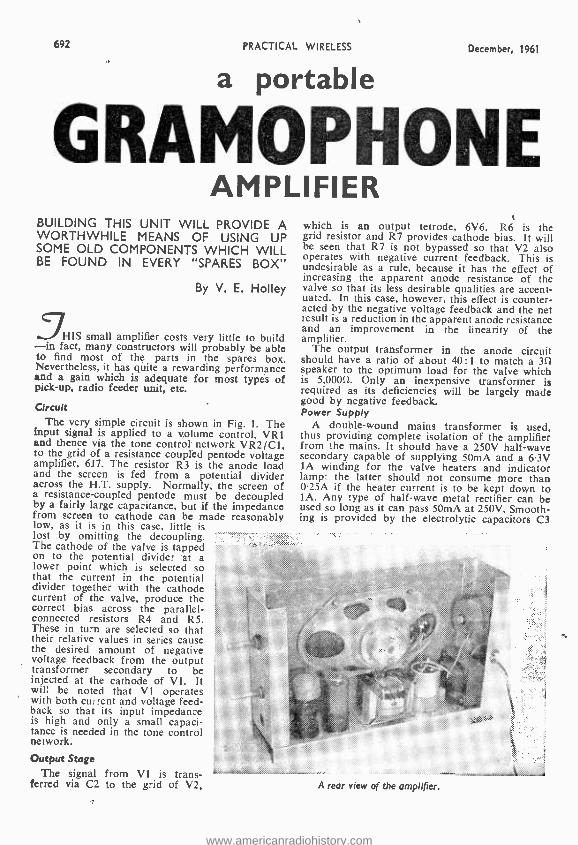
692 PRACTICAL WIRELESS December, 1961
a portable
GRAMOPHONE AMPLIFIER
BUILDING THIS UNIT WILL PROVIDE A WORTHWHILE MEANS OF USING UP SOME OLD COMPONENTS WHICH WILL BE FOUND IN EVERY "SPARES BOX"
By V. E. Holley
HIS small amplifier costs very little to build -in fact, many constructors will probably be able to find most of the parts in the spares box. Nevertheless, it has quite a rewarding performance and a gain which is adequate for most types of pick -up, radio feeder unit, etc.
Circuit .
The very simple circuit is shown in Fig. 1. The input signal is applied to a volume control, VR1 and thence via the tone control network VR2 ¡C1, to the grid of a resistance coupled pentode voltage amplifier, 6J7. The resistor R3 is the anode load and the screen is fed from a potential divider across the H.T. supply. Normally, the screen of a resistance -coupled pentode must be decoupled by a fairly large capacitance, but if the impedance from screen to cathode can be made reasonably low, as it is in this case, little is lost by omitting the decoupling. The cathode of the valve is tapped on to the potential divider at a lower point which is selected so that the current in the potential divider together with the cathode current of the valve, produce the correct bias across the parallel - connected resistors R4 and R5. These in turn are selected so that their relative values in series cause the desired amount of negative voltage feedback from the output transformer secondary to be injected at the cathode of VI. It will be noted that VI operates with both current and voltage feed- back so that its input impedance is high and only a small capaci- tance is needed in the tone control network.
Output Stage The signal from V1 is trans-
ferred via C2 to the grid of V2,
which is an output tetrode, 6V6. R6 is the grid resistor and R7 provides cathode bias. It Will be seen that R7 is not bypassed so that V2 also operates with negative current feedback. This is undesirable as a rule, because it has the effect of increasing the apparent anode resistance of the valve so that its less desirable qualities are accent - uated. In this case, however, this effect is counter- acted by the negative voltage feedback and the net result is a reduction in the apparent anode resistance and an improvement in the linearity of the amplifier.
The output transformer in the anode circuit should have a ratio of about 40:1 to match a 3f1 speaker to the optimum load for the valve which is 5,0000. Only an inexpensive transformer is required as its deficiencies will be largely made good by negative feedback. Power Supply
A double -wound mains transformer is used, thus providing complete isolation of the amplifier from the mains. It should have a 250V half -wave secondary capable of supplying 50mA and a 6.3V IA winding for the valve heaters and indicator lamp: the latter should not consume more than 025A if the heater current is to be kept down to 1A. Any type of half -wave metal rectifier can be used so long as it can pass 50mA at 250V. Smooth- ing is provided by the electrolytic capacitors C3
A rear view of the amplifier.
www.americanradiohistory.com

December, 1961
au fen
a Top cap
grid
6.17
screen
a
h
6V6
supix
np
Input
int octal) grid
VR1 SOOk Volume
S 4 S L'
RI R 47k ,..470k
V1 bJ7 3
1
i
R2 68 !-- V P2 500k Tone
Cl SOOpF
PRACTICAL WIRELESS
C2 e0O1pF
7
Ta RS 470k S
IJLFe Cn1 ± t
3II LS7 fr+
) O C3 C4 32pF 16pF
Mains Transformer
2.2k> `390R 2î {
a
6.3V heaters
250V
693
Metal Rectifier
MRI
SI On /Off switch
Fig. 1 (above).-The complete circuit diagram.
From Pick -up
Feedback
VR1 VR2 and Pilot lamp displaced to clarity wiring
Fig. 2 (below). -The above- chassis wiring.
Smoothing\,capac itors (can negative)
L.F. Choke
MR1 Metal Rectifier
Pilot To cathode of VI lamp (pin B)via R4\
Top cap (grid) V2 6V6
To Loudspeaker U To .--,htr.'s
Output Transformer
6.3V line VI 6J7
Tags marked MC. denote'earthing connections to chassis
To anöde of V2 `To screen grid (pin 3) of V2 (pin 4)
and C4 in conjunction with the choke Chi and, as the hum is very well taken care of by negative feedback, it is not necessary that the choke should have a large inductance.
Construction There is nothing critical about the lay -out and
the amplifier can be constructed in any form suit- able for the purpose for which it is to be used. The prototype was built to fit into a commercial record player cabinet of conventional shape, having a vertical section to the left of the turn- table measuring about 12ín. x 9in. X 3in. and this form will be described.
The speaker is mounted on a piece of plywood or hardboard 11ín. X 61ín. and the amplifier chassis which is 21in, wide is secured to the hard- board by 4B.A. bolts, two at each side and two at
MC
To Mains VeJ Transformer 6.3V
250V
the bottom. The arrangement will be clear from
the illustration. The chassis is of 18 -gauge aluminium sheet to the measurements given in Fig. 4. The mains transformer is mounted separately in the player cabinet underneath the motor board, remote from the pick -up, and its output is taken to the chassis at a point adjacent to MR1 by a 3 -core cable -H.T., L.T. and common negative. The transformer can thus he of any reasonable shape and size and there will be no interaction between it and other components. The switch S1 is fitted to the cabinet adjacent to the point of entry of the mains lead.
Components and Wiring All the components are standard and there is
plenty of room for them in the chassis -in fact, there is considerable scope for miniaturisation to
www.americanradiohistory.com
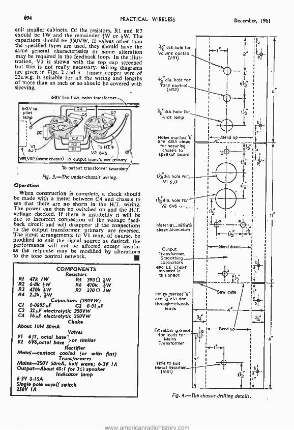
694 PRACTICAL WIRELESS December, 1961
suit smaller cabinets. Of the resistors, R1 and R7 should be 1W and the remainder #W or ;W. The capacitors should be 350VW. If valves other than the specified types are used, they should have the Wit, same general characteristics or some alteration 2e may be required in the feedback loop. In the illus- tration, Vi is shown with the top cap screened but this is not really necessary. Wiring diagrams are given in Figs. 2 and 3. Tinned copper wire of 22s.w.g. is suitable for all the wiring and lengths of more than an inch or so should be covered with sleeving.
3,4 dia. hole for Volume control
(VRt)
3/ "dia. hole for Tone control
(VR2)
6.3V Ilne from mains transformer
6.3V pilot lamp
VRI.VR2
to
6J7 (above
.
6 7
0 Sib dia hole for Pilot lamp
Holes marked '13 are 4BA clear for securing chassis to
speaker board
saw R5
e O, 05 ` 5 ,
`7 7 O
IBM 4 R6
ToH.T.t 6V6
primary
\ 3
.7*-311
V2
chassis) To output transformer
To output transformer secondary
Fig. 3. -The cinder-chassis wiring.
Operation When construction is complete, a check should
be made with a meter between C4 and chassis to see that there are no shorts in the H.T. wiring. The power can then be switched on and the H.T. voltage checked. If there is instability it will be due to incorrect connection of the voltage feed- back circuit and will disappear if the connections to the output transformer primary are reversed. The input arrangements to VI may, of course, be modified to suit the signal source as desired; the performance will not be affected except insofar as the response may be modified by alterations to the tone control network.
RI 47k 1 W R2 6.8k -kW R3 470k ¡W R4 2.2k, ; W
Capacitors (350VW) CI 0.0005µF C2 0.01 µF C3 32µF electrolytic 350VW C4 16µF electrolytic 350VW
Choke
COMPONENTS Resistors
RS 3905 ;W R6 470k --&W R7 270 S2 IW
About I0H SOmA Valves
VI 6J7, octal base } or similar V2 6V6,octal base Rectifier
Metal -contact cooled (or with fins) Transformers
Mains -250V 50mA, half wave; 6.3V IA Output -About 40:1 for 3 S2 speaker
Indicator lamp 6.3V 0.15A Single pole on/off switch 250V IA
1%8 dia, hole for_ V1 6J7
tit
Bend up -..- 1
411/
ti8 dia. hole for V2 6V6 .... 41/
,
Material 18SWG sheet Aluminium
Output Transformer. Smoothing capacitors
and LF Choke mounted in this space
Holes marked 'a' are 1/4 dia. for through -chassis
leads
Fit rubber grommet for leads to
Mains Transformer
Hole to suit Metal Rectifier
(MR1)
i+
bÌ
114
-Bend down--.0.-
Saw cuts
4 I '/4 1-Bend up -.4.-
1%z 1T
I4 .
6N
6*
Fig. 4. -The chassis drilling details.
www.americanradiohistory.com

December, 1961 PRACTICAL WIRELESS 695
An Improved Valve -Voltmeter
A FEW MODIFICATIONS TO AN INSTRUMENT DESCRIBED IN P.W.
MARCH 1961, WILL PROVIDE THE
CONSTRUCTOR WITH AN EXTREMELY
RELIABLE UNIT.
By M. L. Michaelis
General Description This circuit is specifically based on the circuit
principle already introduced by Mr. J. B. Dance on pages 996 to 998 of the March 1961 issue of Practical Wireless. Thus it uses the same form of cathode -coupled balanced D.C. Amplifier as the basic circuit. Upon experimenting with Mr. Dance's circuit, the author devised a number of modifications, which led to the production of this article. This does not mean that any fundamental criticism is intended against the former circuit; on the contrary. Mr Dance's circuit as such is perfectly sound, and was found to function very well when his instructions were exactly followed. This present article is merely intended to present some additions and further ideas..
New Circuit Features
The basic circuit is already taken to be under- stood from the previous article. If readers do not have the relevant issue of Practical Wireless to hand, then that need not disturb practical issues, as completely new theoretical circuit and clear wiring- diagrams are provided here. It is
intended to discuss here only the circuit modifi- cations made, and to explain the reasons for them, and then to give such other practical in- formation as is considered necessary to build the present circuit.
The main new feature here is the built -in cali- brator circuit. This provides, from the A.C. heater supply, a D.C. reference -voltage of exactly 5V. When the unit has been connected to any available power supply, the range- switch is first set to the "adjust calibration" position, and built -in meter -shunt VR2 (see Fig. 1) is turned until exactly full -scale deflection results. (" Electrical Balance " (Zero) must of course have been set pre- viously with VR1.) In this way the meter sensi- tivity is automatically adjusted to suit the H.T. voltage which happens to be used, and the cali- bration holds on the measuring ranges for any H T. voltage supply for operating the unit, as long as it lies between about 250 and 350V. With the circuit of Mr. Dance, the calibration held only
VALVE MAHTER
The complete unit.
for one particular H.T. voltage supply, so that his unit needed to be calibrated for use with one particular H.T. supply.
Zener Diode
The calibrator uses a normal meter -rectifier bridge in half -wave connection for rectifying a sample of the heater voltage. C4 acts as smooth- ing, and the zener diode (D2) with R12 stabilises the D.C. to exactly 5V. A zener diode is a semi- conductor -diode much resembling a transistor in appearance, and has the following properties: if its anode is made positive to its cathode, then it conducts exactly as any other diode. If its anode is made negative to its cathode, then at first it does not conduct, again the same as any other diode. but if this negative voltage exceeds a cer- tain value called the zener voltage, then the diode
www.americanradiohistory.com

696 PRACTICAL WIRELESS December, 1961
COMPONENTS LIST Resistors
Wattage ratings generous for stability ±20% tolerance except where otherwise stated RI 47k ,W Carbon Rl! 100k IW R2, R3 10M 1 W ±5% R12 20k z W R4 2.2M 1W ±5% R13 1k 2W RS 4.7M IW ±5% R14 4.7k 1W R6 680k IW +5% RIS 4752 1W w.w. R7, R8 150k IW ±5% R16, R 17 I k IW R9 220k IW ±5% R18 6.8k 2W RIO 470k IW R19 4.7k 2W VRI 1k Lin. w.w. and knob VR2 1052 Lin. w.w. and knob
Condensers CI OI µF 500VW paper C2, C3, CS 0.01 µF 500VW paper C4 100µF I2VW electrolytic C6 8µF 350VW electrolytic
Valves, etc. VI ECC8I B9A base (ceramic) DI 0A79 or other R.F. /A.F. Diode D2 5 -volt zener diode (G.E.C. 5X 51) MR! Instrument rectifier bridge (from kit)
Sundries Coaxial socket Two coaxial plugs I2 -way tagstrip 7 -way tagstrip Ceramic wafer switch, 2 -pole 5 -way and knob 3 -pole panel socket Meter, 2 S2 2mA FSD, moving coil 1 From Metal box chassis, tin x 4in. x gin. J kit Wire, solder, tags, etc. L1: R.F. choke -see text The construction is founded on chassis, meter,
and some other parts, as found in the "Elpreq" multimeter kit, by "Electronic Precision Equip- ment" advertised in "Practical Wireless".
The existing chassis drilling is maintained. Some holes are enlarged, according to parts used. Extra holes for bolts as required, according to parts to hand. Power Supply
6.3V 0.3A heater 300V H.T., 10mA (250 -350V permissible without loss of accuracy)
Ì l Coaxial
.1 Input
Ranges 1._...SV RMS AC. 2..._.Adjust Calibration 3. -...5V D.C.
4_...5OV D.C.
5.._..5O0V D.C.
LI A
Prod D.C. test E lead
Heater 63V 03A
R19 RI8 6.8k Power supply socket
R12 2Ok VR1
1k w.w cathode
D2 C4 R'1 anode
100}F 1OOk 12VW
Cl 01yF
HT.+ Zero 250 -35OV set 1OmA
Meter 2mA 20
4701
VR2 10R w.w.
L7 fD1 OA79
47k
0,012F
Calibration Adjuster 1 V1
ECC81
Prod E
AG Probe
R8
k 0.O1yF 001j1F
R13 R14 1k 47k
Chassis
Fig. 1. -The circuit of the instrument.
Earth
www.americanradiohistory.com

December, 1961 PRACTICAL WIRELESS 697
Power supply socket
Earth
Cl
63V htr's
MC 0
L1 R.F.C.
Calibration Adjuster
H.T.+
Input socket
MC.
VR2
R 10
, s R9 1
.I + 1M RI
112111
r 0 .' 0
MC -JI) 111211 cathode _
(74.
+; C4 -
anode
Zener diode
VR1 Zero set
taglstrip jolt RB
Bend up along dotted lines
/4;-;,'._ 5.
MC Range Switch
OP Tags marked MC. denote 'earthing' connections
to chassis
Valveholder looking on pins
r` V1
ECC81
- R15
-ve
+ve
Meter 2mA
. 112111
+ C6 -
tagstrip
(0)
9.
Fig. 2. -The complete wiring diagram -the sides are shown bent flat to clarify the wiring.
suddenly conducts again. Thus, in the circuit here described the zener diode D2, which has a zener voltage of 5, always draws just that amount of current through R12 to keep its cathode at exactly 5V positive to chassis (R12 may be altered in value to bring the cathode voltage of D2 to exactly 5. R12 should not be made less than 2.7k.)
The second major modification to the original circuit is a drastic change in the circuit -values connected with the anode circuits, to make the whole circuit of lower impedance. This is to suit it to a cheaper and less sensitive meter than the one specified by Mr. Dance, whilst nevertheless maintaining the original high input impedance with consequent high overall -sensitivity. The main reason for this modification is that the whole circuit was designed to be built using chassis and many parts of a Multimeter Kit advertised in this magazine. The author has purchased several of these kits, and after building one up as originally intended, experimented by modifying the others to various other circuits. The present instrument is one of the results.
4
2'
/
The kits almost always used moving-coil meters of basic sensitivity 2mA FSD, and about 251 in- ternal resistance, and the present circuit values were adapted for this type of meter. The 1k
potentiometer in the kit, originally intended for " ohms zero", serves here as VR1 for the elec- trical- zeroing. The meter -rectifier bridge in the kit serves as the calibrator- rectifier, and is con- nected as half -wave rectifier, by shorting the A.C. connections to each other, and using only the D.C. connections as shown in the circuit diagram. The chassis is used as it is. The holes originally for the two test leads are to take the input coaxial socket and the miniature 3 -pole power -supply socket. VR2 is fitted through the existing hole originally intended for the multimeter voltage/ current selector, and the range switch maintains its original position. The switch in the kit is
rejected to the spares box, and a high- insulation ceramic -wafer switch is here used for the range switch. VR1 maintains its original position. Apart from a few simple holes for mounting -bolts of tagstrips, earthing tags and the valveholder,
www.americanradiohistory.com
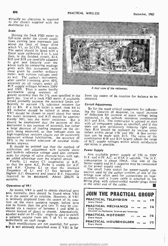
698 PRACTICAL WIRELESS
virtually no alteration is required to the chassis supplied with the multimeter kit.
Scale
Driving the 2mA FSD meter to full -scale under the circuit condi- tions existing here represents just about the limit of linear drive which V1, an ECC81, will accept. The meter should be fitted with a linear scale calibrated 0 to 5, and then, in the finished circuit, R14, R15 and R18 are carefully adjusted to give best linearity over the whole scale by comparing readings given with this instrument with those given by another ordinary meter, with various voltages used as test. The author's instrument, after careful trimming, gives 10% accuracy on all ranges, under all H.T. supply voltages between 250V and 350V. Thus it seems hardly worthwhile using resistors of greater accuracy than the 5% ones specified in the parts list. Use of a lmA FSD meter, if available, would probably increase the accuracy limits suf- ficiently to warrant 1% tolerance resistors for R2 to R9. If a ImA meter is used, then R4 to R8 inclusive should be halved in ohms value. VR2 should be chosen to equal about five times the meter resistance, and R15 should be approxi- mately 50fí, less the meter resistance. But it should be emphasised that the purpose of this instrument is not increase of accuracy, but rather a large decrease of loading imposed on the cir- cuits being measured, so that voltages even on high -impedance resistors chains can be' accurately measured without falsification. An accuracy of 10% is the normal tolerance of amateur multi - meters anyway.
It should be pointed out that the method of calibration and adjustment with variable shunt and built -in reference voltage used also compen- sates for change of valve characteristics with age, an added advantage over the original circuit.
Finally, LI makes Cl inoperative at R.F., so that the same A.C. Probe is usable for A.F. and R.F. Choose Li so that the resonant frequency of LI and Cl lies between the highest A.F. frequency and lowest R.F. frequency required to be measured. About 200µH is suitable.
December, 1961
' .........
Operation of VR I As stated, VR1 is used to obtain electrical zero
and; normally, zero should be found when VR1 is at the centre of its rotation. However, if VR1 is seriously displaced from the centre of its rota- tion on the more sensitive ranges, before zero can be found, then the grid (pin 7) may be con - nected via a resistor of between 1 and 10M to chassis instead of direct to chassis. Alternatively, another wafer on SI -Slc -might be used to switch a suitable resistor from pin 7 of VI to chassis individually on each range.
Such modifications are not essential, for accur- acy is not seriously disturbed even if VR1 is far
A rear view of the voltmeter.
from the centre of its rotation for balance to be obtained.
Circuit Adjustments By far the most critical component for influenc-
ing the linearity of response, i.e. equal increase of deflection for increase of input voltage being measured, is the cathode resistance combination R13 and R14. The constructor is advised to start with all component values as specified, and if this does not give satisfactory linearity right away, then R14 should be replaced by various other values within about 2.5k and 10k. A fine correc- tion can be made with R15. The value of the combination R18 and R19 largely affects the range of H.T. supply voltages within which satisfactory operation is possible.
Power Supply Any available power supply of 250 to 350V
H.T. and 6.3V A.C. at 0.3A is suitable. The H.T. consumption is about IOmA. One side of the heater supply and H.T. negative may be commoned in the power supply used.
The small 3 -pin socket for power -supply con- nection used by the author consists of one of the fittings now often used for connections on tape - recorders, and a 3 -core cable is attached to the fitting plug, with colour -coded wander -plugs fitted at the other end of the cable.
JOIN THE PRACTICAL GROUP PRACTICAL TELEVISION .,
Every Month 119
PRACTICAL MECHANICS ... ... ... 116 Every Month Devoted co Mechanics, Science and Invention
PRACTICAL MOTORIST ,.. 116 Every Month
PRACTICAL HOUSEHOLDER .. 113 Every Month
www.americanradiohistory.com
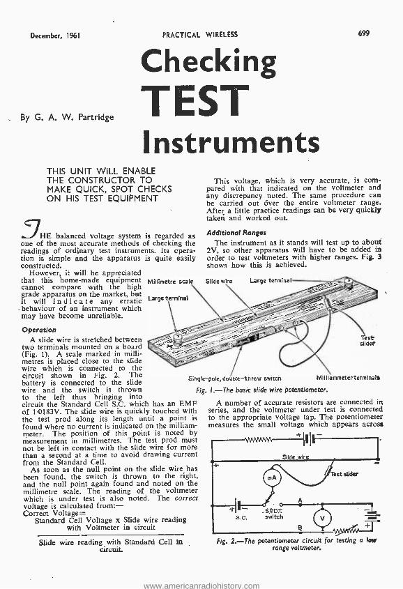
December, 1961 PRACTICAL WIRELESS 699
By G. A. W. Partridge
Checking TEST Instruments
THIS UNIT WILL ENABLE THE CONSTRUCTOR TO MAKE QUICK, SPOT CHECKS ON HIS TEST EQUIPMENT
JHE balanced voltage system is regarded as one of the most accurate methods of checking the readings of ordinary test instruments. Its opera- tion is simple and the apparatus is quite easily constructed.
However, it will be appreciated that this home -made equipment cannot compare with the high grade apparatus on the market, but it will i n d i c a te any erratic
. behaviour of an instrument which may have become unreliable.
Operation A slide wire is stretched between
two terminals mounted on a board (Fig. I). A scale marked in milli- metres is placed close to the slide wire which is connected to the circuit shown in Fig. 2. The battery is connected to the slide wire and the switch is thrown to the left thus bringing into circuit the Standard Cell S.C. which has an EMF of 1.0183V. The slide wire is quickly touched with the test prod along its length until a point is found where no current is indicated on the milliam- meter. The position of this point is noted by measurement in millimetres. The test prod must not be left in contact with the slide wire for more than a second at a time to avoid drawing current from the Standard Cell.
As soon as the null point on the slide wire has been found, the switch is thrown to the right, and the null point again found and noted on the millimetre scale. The reading of the voltmeter which is under test is also noted. The correct voltage is calculated from: - Correct Voltage=
Standard Cell Voltage x Slide wire reading with Voltmeter in circuit
Millimetre scale
Large terminal
This voltage, which is very accurate, is com- pared with that indicated on the voltmeter and any discrepancy noted. The same procedure can be carried out river the entire voltmeter range. After a little practice readings can be very quickly taken and worked out.
Additional Ranges
The instrument as it stands will test up to about 2V, so other apparatus will have to be added in order to test voltmeters with higher ranges. Fig. 3 shows how this is achieved.
Slide wire Large termina
Test slider
Single -pole, double -throw switch Milliammeterterminals
Fig. 1. -The basic slide wire potentiometer.
A number of accurate resistors are connected in series, and the voltmeter under test is connected to the appropriate voltage tap. The potentiometer measures the small voltage which appears across
Slide wire reading with Standard Cell in circuit.
Fig. 2. -The potentiometer circuit for testing a low range voltmeter.
www.americanradiohistory.com

700
To single -pole double -throw switch
(A in Fig.1)
"lb potentiometer + (B in Fig,l) -}-
Fig. 3 (above).- Circuit for testing high -range miters.
-500V
-250v
PRACTICAL WIRELESS December, 1961
The measurement of current is also carried out with resistors. Fig. 5 illustrates the method. Assume that the milliammeter is scaled to 100mA. The IOOmA shunt is connected as shown and gives 2V when 100mA is flowing through it. The ratio in this case will be 50. For example if the voltage measured is 1.35 then the current flowing through the milliameter is 1-35 x 50= 67.5mA.
The slide wire is made from resistance wire of about 2f1 per yard. This is not critical, but the higher the resistance the higher the voltage that cad be measured. It is just over a meter in length and is stretched tightly between two terminals one meter apart on a wooden base 4ft. x 4in. x +in. The meter rule or tape is held in position by }in screws or tacks.
The switch which is of the single- pole -double- throw type is mounted on the side at the centre of the board. Two terminals are placed tin. apart and about bin. away from the switch as shown in Fig. 1. The nearest terminal is connected by a small length of bell wire to the centre of the switch. The test prod is connected to the other terminal by 3ft of light flex.
Fig. 4 shows the general idea of the volt -box. A row of terminals are mounted on the box which
YC
Supply
+ve
To S.PD.T, switch
Shunt
Fig. 4 (above). -The volt -box.
Fig. 5 (left).- Testing To
a milliammeter.
+ve }
resistor A which is proportional to the voltage across the voltmeter. The tests are carried out in the same way but the voltage on the potentio- meter is multiplied by the appropriate ratio. For example, the voltage across A will be 2 when 250V is applied to the 250V tap. Therefore 250 =125 which is the ratio in this case. 2
The Tap Tap Tap Tap
ratios for the taps are: - 5=2.5 25 =12.5 250 =125 500 =250
00214 (B)3k (C)2Ok (D)225k (E)25Ok
Fig. 6. -Rear view of the volt -box showing the resistors in position.
Shunt wound on fixed resistor 2.
Fig. 7. -A current shunt..
is made from stiff cardboard. Fig. 6 illustrates the internal connections. When ordering the resistors state that they are for measurement so that the supply firm will pro-
vide more accurate resistors than those used for ordinary radio work. They may cost a little more but for accurate tests they are essential. Five +W resistors are required, and the values are: - A= 200011; 8= 3000(1; C= 20.00011; D= 225,000(1;
E= 250,00011. The shunts, or current measuring resistors, are each mounted separately on wooden bases with
terminals as shown in Fig. 7 with the current range marked clearly on them. The IOmA shunt is 2000; the 100mA shunt is 2011; the 500mA shunt is 40.
These resistors are obtainable along with the Weston Standard Cell (small type) from the Doran Instrument Co., Stroud, Glos.
There are a few points that must be borne in mind while operating this test set. First, all con- nections must be as tight as possible. Second, the test prod must not be in contact with the slide wire for more than a second at a time. Third, the Standard Cell must 62 kept in a cool place. Fourth, not more than IA must pass through the slide wire. Use two large 11V dry cells with a 1(1 1W resistance in series. Finally, give the slide wire about two minutes to warm up before starting work, and tighten it if necessary,
www.americanradiohistory.com

December, 1961 PRACTICAL WIRELESS 701
Easy-to- build kit - sets of
THE "MOHICAN" GENERAL COVERAGE RECEIVER Model GC -1U Fully transistorised. moudmg 4 piezo- electric trans- filters. The very latest and an excellent portable or Fixed Station receiver for the Ham and £38.15.0 short -wave listener.
SHORT -WAVE TRANSISTOR PORTABLE Model RSW -1 Extending aerial, leather case, our band (2 short -wave bands Trawler and Medium). £22.10.0 6- TRANSISTOR PORTABLE Model UXR -1 Pre -a igned i.r. crac:srormers, printed et cult, i x 41n.
high -flux speaker Real hide case. £14.18.6 DUAL -WAVE TRANSISTOR RADIO UJR -1 This sensitive headphone set is a tine introduction to electronics for any youngster. £2.16.6 HI -FI F.M. TUNER Tuning range 68 -108 Mc /s. For your convenience this is available in two units sold separately: Tuning Unit (FMT -4U) with 10.7 Mc /s. I.F. output E3.5.0 (inc. P.T.). I.F. Amplifier (FMA -4U) complete with cabinet and valves (EI1.11.0). £14.16.0
HI -Fl 16W STEREO AMPLIFIER Model S -88 20mV. basic sensitivity k4 mV. available, 7i6 extra.) Ganged controls. Stereo- Monaural gram. radio and tape recorder input. Push -button selec. £26.12.6 Lion. Two -tone grey metal cabinet.
6W STEREO AMPLIFIER Model S -33 3 watts per channel, 0.3% distortion at 2.5 wlchn 20dB N.F.B. Inputs for Radio (or Tape) and Gram. Stereo or Monaural, ganged controls. £12.8.6 Sensitivity 200 mV.
TRANSCRIPTION RECORD PLAYER, GL -58 Goldring -Lenco tour speed unit. G.60 pick -up arm and infinitely variable speed adjustment between 33/, and 80 r.p.m. with fixed speed at 16, 33 , 45 and 78 r.p.m. Balanced turntable (31 lb.).
£20.12.2 Stereo. HI -Fl SPEAKER SYSTEM Model SSU -1 Ducted -port bass reflex cabinet "in the white" Twin speakers. With legs LI 1.18.6. £10.17.6 "COTSWOLD" HI -FI SPEAKER SYSTEM KIT Acoustically designed enclosure "in the white" 26 x 23 x I51in., housing a 12in. bass speaker with tin. speech coil, elliptical middle speaker and pressure unit to cover the full frequency range of 30- 20,000 c/s Complete with speakers, cross-over unit, £21.19.0 level control, etc..
COMPLETE MATCHED STEREO OUTFIT includes record player, amplifier and twin speaker systems (pedestal speaker 'egs optional L2.2.0 extra). £44.9.4 STEREO CONTROL UNIT USC -1 Luxury model with press -button inputs to suit any pick -up or tuner and most tape - heads. Output 1.3 v. R.M.S. per channel. Printed circuit construction. £18.18.6
MULTIMETER Model MM-1U Measures wide range of vo,tage, current, resistance and dB in over 20 ranges. Sensi- tivity 20,000 ohms /volt D.C. and 5,000 ohms /volt A.C. 0 -1.5, 1,500 volts A.C. and D.C. 0 -f 50gA, 15 A D.C. Resistance 0.20 to 20 MU. 4 4-in. meter, £11.18.6 50 uA l.s.d. r
L
F.M. TUNER
S.33
5.88
UXR-1
OS-I
S5U-I
AG.9U
Please send me FREE CATALOGUE (Yes /No)
Full details of model(s)
NAME
ADDRESS
GC.I U Ì
PW12
highest quality at lower cost
AMATEUR TRANSMITTER Model DX -1000 Covers all amateur bands from 16u -10 metres. ISO watts D.C. .nput. Sell- contained includ- ing £ß1.1O.0 Power Supply Modulator V.F.O.
AMATEUR TRANSMITTER Model DX -40U From 80-IU m. Power input /5 w. C.W., 60 w. peak C.C. phone. Output 40 w. to aerial. Com- £32.10.0 pact and sell- contained. Prov. for V.F.O.
VAR. FREQ. OSCILLATOR VF -1U Caubrateo In0 -Iv m. Fundamental: on 160 & 40 m. Ideal for our CX -40U and imila £11.2.0 transmitters. R.F. SIGNAL GENERATOR Model RF -1U Up to 100 Mc /s fundamental and 200 Mc/s. on harmonics and up to 100mV. output on all £11.18.0 bands.
AUDIO SIGNAL GENERATOR Model AG -9U 10 cis to 10u kcis. switch selected. Distortion less than 0.1°,., 10 v. sine wave output £19.19.6 metered in vole and dB's.
VALVE VOLTMETER Model V -7A Measures volts to 1,500 D.C. ( and R.M.S.) and 4,000 pk. to pk. Res. 0.1 11 to 1,000 M O. D.C. input imped. 1 1 MII. Complete with test prods £13.0.0 leads and standardising battery.
Portable 23/4 in. SERVICE 'Scope Model OS -1 Compact portable scope ideal for servicing and general work. Y amplifier sensitivity 10 mV /cm; response ± 3 dB IO c /s -2.5 Mc /s. Time base 15 c/s.150 kc/s. Printed circuit. Cue Ti x 41 x 12 }in. £19.10.0 Wt. only 10 }Ib.
5 in. OSCILLOSCOPE Model 0 -12U Has wide -band amplifiers, essential for TV servicing. F.M. alignment, etc. Vertical freq. response 3 c /s. to over 5 Mc /s. without extra switching. T/B £36.10.0 covers 10 c/s to 500 kc /s. in 5 ranges.
RES. -CAP BRIDGE Model C -3U Measures resistance 1000 to 5M1.2, capacity 10pF to 10000, and power factor. Test voltages f8.6.6 5-450 v. with automatic safety switch.
SINGLE CHANNEL AMPLIFIER, MA -12 10 -12 watt H, -FI amplifier. Extremely low
£10.19.6 distortion and wide frequency range.
HI -FI EQUIPMENT CABINETS Range of cabinets available with at least one to suit your particular needs. From small to large, housing Tape Deck, Record Player and full equipment. In the white for finishing to personal taste.
From £11.5:6 to £17.18.6
GRID DIP METER Model GD -lU Coverage from I Mc/s. to 250 Mc /s. Complete set of plug -in £10.9.6 coils provided. TAPE RECORDING /PLAYBACK AMPLIFIER Model TA -1 Monaural ITA -IM) L18.2.6. Conversion unit to Stereo E6.10.0. Stereo £23.6.0 (TA -IS).
`PACKAGED DEALS' of HI -F1 Equipment including TAPE DECKS RECORD PLAYERS and DECCA ff.. PICK -UPS. Write in to see how these deals save you further money.
All prices include free delivery to UK Deferred Terms
available on orders over £10
DAYSTROM LTD. Dept. P.W. 12, GLOUCESTER, ENGLAND
A member of the Daystrom Group, manufacturers of the
WORLD'S LARGEST -SELLING ELECTRONIC KITS
www.americanradiohistory.com

December, 1961
R.T., I.F. and A.T. Signal Generator
PRACTICAL WIRELESS
5 HIS unit requires very few parts, and runs from a 22-¢V, B112 or similar miniature layer H.T. battery, with a 1 }V cell for the filament. It produces a modulated radio frequency signal, which can be used to test or align R.F. and 1.F. stages in a receiver, or to calibrate home constructed sets. An audio output is also available, and this is suitable for stage -by -stage tests of A.F. amplifiers, or the audio circuits of receivers.
It is possible to calibrate the generator tuning dial by means of a receiver, as will be explained. Despite its simplicity, the generator will be found to be very useful for aligning, trimming, and test- ing TRF and superhet receivers of mains, battery, and transistor type.
Circuit The circuit is shown in Fig. 1, and component
values are so arranged that the R.F. oscillations are interrupted at audio frequency by grid block- ing. The A.F. output socket provides an audio tone which is used for testing speakers, and A.F. amplifier stages. The R.F. output socket gives modulated R.F. at the frequency to which the generator is tuned. A single switch selects either of the two tuning ranges, and has an " off " position. A separate filament switch could be used, and a 2 -pole, 2 -way switch would then suffice for range selection.
703
THIS BATTERY - OPERATED UNIT WILL
BE FOUND INVALUABLE IN CALIBRATION, ALIGNMENT,
ETC.
By F. G. Rayer
The two coils used were arranged to cover about 1,600kc /s to 500kc /s (about 190 -600m) and 500kc /s to 170kc /s (about 600- 1,800m). This includes 465kc /s, for I.F. alignment, in addition to all the usual medium -wave band, and most of the usual long -wave band. Harmonics are available up to 30Mc /s.
The M.W. coil was a standard air -cored type, with the addition of a dust core. For L.W., a standard -cored L.W. coil was found suitable, with the core almost unscrewed. The coils should be of the type which have reaction windings.
Valves other than the 1S4, may be used, 3S4, DL92, and similar types being satisfactory. The holder must, of course, be wired to suit.
Switch Positions t off 2 Range 1
3 Range 2
Fig. 1.-The circuit of the instrument.
www.americanradiohistory.com

704 PRACTICAL
The cabinet is a 6in. x Tin. x 2in. " universal chassis " with extra 6in. x Tin. back plate. An extra 7in. x 2in. runner forms the chassis.
The panel layout is shown in Fig. 2. The sockets of the twin strip project through clearance holes. The chassis should be bolted to the panel, but the generator should not be installed in its cabinet until finished.
Fig. 3 will act as a guide to marking out the tuning scales. The exact position of markings will depend on the tuning condenser, coils, and other
Panel dimensions 7 "x 6'
. Fig. 2. -The layout of the front panel.
factors, and can be obtained as described later. The scale is cemented to the tuning knob, and rotates with the knob, readings being taken off at the panel mark- ings shown in Fig. 2.
Generator Wiring Fig. 4 shows connections and
components, the underside of the valveholder being included so that pins may be seen. The tuning condenser should be of the full SOOpF capacity, for the coverage mentioned, and its frame is in con- tact with the aluminium panel.
An L- shaped clip is cut from scrap metal, and drilled so that the switch secures it to the panel. The arms of the clip are bent to hold the l +V filament cell, and 22+V H.T. battery, as in Fig. 4. Current consumption is small, and to avoid crackling, owing to poor contact, the battery leads are soldered directly to the batteries. This should only be done after completing other wiring.
The switch has three positions. One is for " off " and no circuit is completed, the unused contacts being ignored or cut off. With the switch in its next position the fila- ment circuit is on, and the first tuning coil is connected. G2 and P2 indicate Grid and Plate (re- action) tags of coil 2. In the final
WIRELESS December, 1961
switch position, coil I is in circuit, G1 and Pl indicating Grid and Plate tags of this coil. The filament is also switched on, as before. The coils can be fixed on brackets, or bolted to the chassis.
Points marked M.C. are connected to the chassis in the usual way. Condenser Cl is formed by winding three or four turns of insulated wire round the insulated covering of the lead from valve to switch, as shown. Check connections against Fig. 4 before inserting the valve and installing the batteries. Use as Audio Generator
For this application, the tuning calibration is of no importance. With the generator switched on, a strong audio tone should be heard in 'phones wired from the A.F. output socket to chassis. The note will vary according to the range selected, and the position of the tuning control.
If this audio tone is heard, this indicates that the generator is also producing its radio frequency signal. If no tone is heard, connections to the reaction windings on the coils may be reversed. Figs. 1 and 4 show usual connections, as indicated by most coil manufacturers. "G" denotes Grid, " P " indicates Plate (reaction) and " R.C." is for Reaction Condenser, with " E " showing the Earth or metal chassis connection.
To make stage -by -stage tests of audio circuits, take an insulated test prod connection from the A.F, output socket of the generator. Apply the prod to A.F. circuit points one by one, working
The instrument with its case removed.
www.americanradiohistory.com
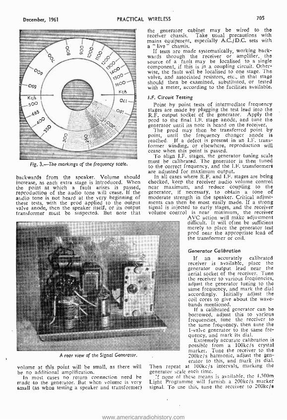
December, 1961 PRACTICAL WIRELESS 705
the generator cabinet may be wired to the receiver chassis. Take usual precautions with mains equipment, especially A.C. /D.C. sets with a " live " chassis.
If tests are made systematically, working back- wards through the receiver or amplifier, the source of a fault may be localised to a single component, if this is in a coupling circuit. Other- wise, the fault will be localised to one stage. The valve, and associated resistors, etc., in that stage should then be examined, substituted, or tested with a meter, according to the facilities available.
Fig. 3. -The markings of the frequency scale.
backwards from the speaker. Volume should increase, as each extra stage is introduced. When the point at which a fault arises is passed, reproduction of the audio tone will cease. If the audio tone is not heard at the very beginning of these tests, with the prod applied to the output valve anode, then the speaker itself, or its output transformer must be suspected. But note that
I.F. Circuit Testing Point by point tests of intermediate frequency
stages are made by plugging the test lead into the R.F. output socket of the generator. Apply the prod to the final I.F. stage anode, and tune the generator until its note is heard on the receiver.
The prod may then be transferred point by point, until the frequency changer anode is reached. If a defect is present in an I.F. trans- former winding, or elsewhere, reproduction will cease when this point is passed.
To align I.F. stages, the generator tuning scale must be calibrated. The generator is then tuned to the correct frequency, and the I.F. transformers are adjusted for maximum output.
In all cases where R.F. and I.F. stages are being checked, keep the receiver audio volume control near maximum, and reduce coupling to the generator, if necessary, to obtain a tone of moderate strength in the speaker. Critical adjust- ments can then be most easily made. If a strong signal is injected to early stages, and the receiver volume control is near minimum, the receiver
AVC action will make adjustment difficult. It will often be sufficient merely to place the generator test prod near the appropriate lead of the transformer or coil.
z_:....... .,..,
..w .: _;n.. ., :...- >
..::::::: :::.,.> . .., .. :,:,r. ,::< <:
A rear view of the Signal Generator.
volume at this point will be small, as there will be no additional amplification.
In most cases no return connection need be made to the generator. But when volume is very small (as when testing a speaker and transformer)
Generator Calibration If an accurately calibrated
receiver is available, place the generator output lead near the aerial socket of the receiver. Tune the receiver to various freqUencies. adjust the generator tuning to the same frequency, and mark the dial accordingly. Initially adjust the coil cores to give about the wave- bands mentioned.
If a calibrated generator can be borrowed, adjust this to various frequencies, tune the receiver to the same frequency. then tune the 1 -valve generator to the same fre- quency, and mark its dial.
Extremely accurate calibration is possible from a 100kc /s crystal marker. Tune the receiver to the 200kc /s harmonic, adjust the gen- erator to this, and mark its dial.
Then repeat at 100kc /s intervals, marking the generator scale each time.
'f none of these means is available, the 1,500m Light Programme will furnish a 200kc /s marker signal. To use this, tune the receiver to 200kc /.
www.americanradiohistory.com

706 PRACTICAL WIRELESS
(e.g. the Light Programme trans- mitter). Tune the generator to this frequency, and mark its scale. Leave the generator tun- ing untouched, and tune the receiver until the generator har- monic on 400kc /s is heard. Leave the receiver tuning untouched, and tune the receiver until the generator harmonic on 400kc /s is heard. Leave the receiver tuning untouched and tune the gen- erator to 400kc /s, and mark its dial. Return the receiver to 200kc /s, readjust the generator to this frequency, then tune the receiver to 600kc /s (ignoring the 400kc /s harmonic already used). Then leave the receiving tuning, and adjust the generator to 600kc /s, and mark its scale. Proceed in this way until the whole of both bands has been calibrated at 200kc /s intervals.
A list of BBC transmitters will give their frequencies, and these furnish additional check points. Tune in the required station, adjust the generator to this frequency, and mark its dial.,
A 465kc /s calibration point for the generator can be obtained by placing the output lead near the I.F. stage of a receiver using this frequency, and tuning the generator for maximum response from the receiver.
December, 1961
M.C.
Points marked 'MC' denote'earthing-
connections to chassis Range Tunings Capacitor =
22 Iv H.T.
Battery
/Clip Range Switch
Coil2 \ \ó To P2
/,4`;/ '
SOOpF, *
Fixed plates . tag
0 -01 u.F
To RC on both coils
1000pF
MC. Chassis bolted; to panel
Valveholder tilted to A.F. Out R.F. Out clarity wiring _____
Fig. 4. -The co
Harmonics As the correct use of harmonics can be
extremely , useful, both for calibrating the generator and for other purposes, it should be noted that these arise at multiples of the frequency to which the generator is tuned. For example, if it is tuned to 200kc /s, its note will be heard at 200kc /s (fundamental), 400kc /s, 600kc /s, 800kc /s, and so on, each harmonic being a little weaker than 'the previous one.
Similarly, if the generator is tuned to 400kc /s, it will be heard at 400kc /s, 800kc /s, 1,200kc /s, and so on, but not at 200kc /s. That is, its harmonics are always multiples of the frequency to which it is tuned.
With an average receiver, the harmonics of 200kc /s can be heard at 200kc /s intervals, right up to 1,600kc /s. With a sensitive receiver, the harmonics may be heard up to 4Mc /s. As the initial setting of the generator can be extremely accurate (e.g. from the 200kc /s Light Programme) the check points thus obtained are very useful indeed for calibrating home -constructed receivers, or similar purposes.
if the generator is tuned to 1,500kc /s, its harmonics can be heard up to 30Mc /s, with a sensitive receiver. With the generator tuned to 1,000kc /s, harmonics may be heard up to about 25Mc /s. These will, of course, be at 1,000kc /s, or ]Mc /s, intervals, and will be extremely useful for calibrating a home -built short -wave set, or for similar purposes.
A simple TRF r e c e i v e r, with reaction, is very satisfactory for helping to calibrate the generator. With reaction sufficiently advanced,
mponent layout and wiring diagram of the complete unit.
the exact tuning point can easily be found. An ordinary superhet is suitable, especially if it
has a tuning meter or magic eye. In this case, the meter or eye will show the correct tuning point. If there is no meter or eye, turn the receiver volume control to maximum, and reduce volume by pro- viding very loose coupling, as already explained.
When adjusting the generator to the same frequency as a radio station, reduce the volume of both signals, disconnecting the receiver aerial if necessary. With a little care, a standard of calibration sufficiently accurate for normal purposes can be achieved. Aligning R.F. Stages
To adjust aerial or R.F. circuits, inject a signal of about 1,400kc /s at the aerial terminal, tune to this on the receiver, and adjust the M.W. trim- mers for best results. Then inject 600 or 700kc /s, tune to this on the receiver, and adjust M.W. coil cores for best sensitivity. Repeat a few times.
If the receiver has a calibrated tuning dial, adjust trimmers and cores for best accuracy of reading, as well as best results. For a home - constructed receiver with uncalibrated dial, adjust for the expected waveband coverage (say 200 - 550m on M.W.). The dial can be calibrated at desired points, from the generator.
Treat each band separately. In simple dual -range receivers with only one pair of trimmers, these are usually adjusted for best M.W. reception. El
PRACTICAL WIRELESS CIRCUITS 17th Edition
By F. 1. CAMM 1716 by post 18'7 from
GEORGE NEWNES, LTD., Tower House, Southampton Street, London W.C.2.
www.americanradiohistory.com

December, 1961 PRACTICAL WIRELESS 707
A
Transistorised COMPLETING THE ALIGNMENT
By D. R. Bowman
(Continued from page 592 of the November issue)
N last month's issue, the first three parts of the alignment procedure were completed.
4- Switch the signal generator to controlled output. Plug in coaxial lead. Bring it to the board and clip the outer braiding to chassis. Connect coaxial cable core (inner) to the base winding of Tr3 via a 25pF capacitor. Leaving ratio detector core (secondary) alone, re -align for maximum output in the loudspeaker. 5- Transfer the signal generator input to the base of Tr2 (C11). Complete alignment of T2 and T3 as before.
6 -Screw in the core of the ratio detector trans- former until it overlaps both primary and secondary windings. Adjust the core of the primary for maxi- mum output. Very carefully screw the core of the secondary in towards the primary, keeping adjustment of the primary by slowly withdrawing the primary core. This is a two -handed operation, aimed at varying the coupling between primary and secondary by the adjustment of the coupling core. Continue until maximum output is heard in the loudspeaker. Then, reverse the direction of travel of the coupling core and rotate 11 turns, adjusting the primary core to maintain resonance. This gives more -than -critical coupling (about 1.5 critical) with little reduction in sound output; the decrease should be just noticeable, not a pro-
VHF Superhet nounced drop off in volume. If 1} turns reversed travel causes a considerable drop in sound, less movement of the core is needed; a reduction of 2dB is ideally required and this may be judged by ear to a sufficient degree of accuracy.
7- Insert a third core in the ratio detector secondary winding. Rotate this to see if a mini- mum output point can be found. If not, use a brass slug instead of a dust core. Rotate the tuning element, whether iron dust or brass, for a mini- mum output between positions of high output. This point will be quite sharp and will be characterised by a change of `quality" of the output tone as the minimum output point is traversed.
8 -Set the signal generator to 90Mc /s and con- nect the coaxial lead to the aerial socket. Set Cl. C13 to approximately half setting and C12 to half capacitance. Rotate the core of Ll until a signal is heard; if a signal is heard in two posi- tions of the core, the setting which gives least inductance is correct.
9 -Set the signal generator to 86Mc /s. Rotate C7, C13 until the signal is heard. This should occur at nearly maximum capacitance; if not, adjust Ll.
10-Set the generator to 100Mc /s. Adjust C12 to hear the signal, and the core of Ti for maxi- mum output.
11-Set to 89Mc /s and locate the signal with tuning capacitor C7, C13. Rotate the core of TL for maximum output.
12 -Reset to 100Mc /s and adjust C12 for maxi- mum output.
13- Repeat the adjustments 11 -12 until no further improvement results.
(Continued on page 712)
www.americanradiohistory.com

708 PRACTICAL WIRELESS December, 1961
BY THERMION
A Recording Problem
IN the details which I gave in the October issue of a tone problem connected with a tape recorder, many readers wrote with suggestions
as to the cause of the trouble, and some very ingenious suggestions were made by some. How- ever, several readers made the same suggestion and it would appear that this is, in fact, the real answer, and it concerns not the material from which the tape is made, nor its manner of storage, but the method of use. A Mr. Berry of Burton -on -Trent says he suffered from this trouble and after experi- menting with different types of tape over a period of time without satisfactory results, he turned his attention to the deck, and located the fault in the pressure which was applied to the tape on the playback head. A small adjustment of the arm holding the pressure pad was the remedy, and since doing this he has had no further trouble.
Electronic Games
Some experimenters find a great deal of enter- tainment in the adaptation of standard electronic techniques to the requirements of'equipment and apparatus which is not normally used in the elec- tronic fields. Recently I saw a most ingenious electronic version of noughts and crosses -not the simple electric method which was seen at a Radio Show some time ago. This was truly elec- tronic and made use of a computer network,: and I was not really surprised when this was followed shortly afterwards by a modification to enable the game of " Nim " to be played. In this, as most of my readers know, a number of matches are laid out and the object is to make your opponent take the last match. This electronic version guarantees success, without worry, and according to the design cannot be beaten. I wonder how many other well -known parlour games have been adapted in this way. No doubt those who are engaged in designing and building computers for industrial purposes often think of other uses for them, a fact which is bound to come up when development work is being carried out. This is an interesting field for experiment by those readers who can follow simple computer design, and, as usual, we shall always be pleased to see the results of a reader's handiwork, and if interesting enough, to publish them. I am sure there must be some very interesting developments possible, even in such games as poker or bridge.
Artificial Troposphere The use of the metallic cuttings for a reflecting
layer to facilitate world -wide television and com- munications has, as I expected, raised considerable controversy amongst scientific men throughout the world. You will probably remember that the U.S.A. proposed that a rocket could fire an immense quantity of these strips into space, where they will form a fairly substantial metal layer from which signals could be bounced, but astronomers are complaining that this would make telescopic viewing even more difficult than it now is, whilst radio telescopic investigators complain that it will give false readings. I believe that the idea has been temporarily shelved, but I wonder if any- unknown effects are likely to result from the various atomic explosions which are made from time to time. V::11 not the radiations which result remain for all time in space, and perhaps gradually form up to make a complete screen round our earth, thus preventing scientific observations of a certain kind, and perhaps even eventually pre- venting satisfactory control of spacecraft designed for the moon and other planets. I often wonder if it is possible for the men engaged in this work to calculate the possible effects over a period of time or whether they are not more interested in the present, as they will not be here later to feel the results of some of these activities. It would be reassuring if the powers concerned could let us have from time to tinie information on this aspect, as well as letting us know that a certain type of explosion has taken place.
FRIDAY, FEBRUARY 2nd, 1962
A FILM SHOW (In collaboration with Mallard Ltd.)
CAXTON HALL, WESTMINSTER
at 7-30 p.m.
Send for your free tickets now marking your envelope "Caxton Hall" in the top left -hand corner and enclosing a stamped addressed envelope (at least 3sin. x 6in.) for the tickets.
The films to be shown will be announced later, but, as In previous years, the pro- gramme will be arranged to appeal to all who are interested In radio.
The demand for tickets will be great; order yours NOW.
www.americanradiohistory.com

December, V961 PRACTICAL WIRELESS 709
*PER- RETURN MAIL ORDER SERVICE IF YOU CANNOT CALL AT EITHER OF OUR ADDRESSES
STEREO AMPLIFIER Kit only 56/..
Twin 4 watt (or 8 watt Monaural) em- ploying two ECL82 and EZ80 REGT Valves, double wound mains transformer, etc., separate panel with base, treble and volume controls. Indicator lamps. Push button on /off switch. Elegant gold/ cream knobs. Kit comprises two ampli- fier units and power unit all 5 x 24n. in size, fully assembled ready to be wired together. Kit is priced without loud- speakers so that you can choose the type and size required. LASKY'S PRICE for the kit 56,. post with 3 new Mallard Valves, 6/6 Full data, circuit diagram, assembly instructions and layout supplied. SPLCI AL OFFER OF SPEAKERS WI ill THIS KIT
Two Sin. for 20 /-: Two 6 x 41n. for 25/- Suitable cabinets available at bargain prices.
MARTIN RECORDER KITS TAPE AMPLIFIERS as advertised KIT A. 4TR Amp for MONARDECK
LASKY'S PRICE 9 Goa. KIT B. 2TR Amp for MONARDECK
LASKY'S PRICE 8 Gns. KIT C. For COLLARO Studio Deck
I1 Gns. Post free by return.
"CLARION" TRANSISTOR BATTERY TAPE RECORDER
Capstan drive, push- button controls. Constant speed 31 l.p.s. using 31n. spools. Size 94 x 5 x 31tn, with transparent upper. New in maker's carton. LIST 25 Gns. LASKY'S PRICE with mike and tap, 1 6 Gns. Carr.
BUILD THE NEW LASKY FM
TUNER FOR L4.19.6 P.P.8 /6
Non -drift permeability lining pack by famous manufacturer, frequency 88 /100 Mc /s. OA51 balanced diode output 21F stages and discriminator. Smart cold and maroon glass dial 7 x 31n. Sell powered. Valve line up ECC85. two EF80's, EZ80 rectifier. Everything ready for assembly. All components available separately. Dimensions: 8 x 8 x 54ín. Optional extra EM84 magic eye tuning indicator. 8/6. Circuit diagram and full data supplied. 1/6 post free.
BATTERY CHARGER BARGAIN Mains Input 203-250 v. A.C. 6 and 12 volts 2 am ?. output.. Latest type rectifier. Metal Case 6 x 3 x 3in. Hammered grey finish. P. & P. LASKY'S PRICF 21 - 3l-
THE NEW "ALBERTA 5" TRANSISTOR POCKET RADIO
Push -pull. 200 milliwatts output. Five transistors and one diode. 2íin. moving coil speaker, lernte rod aerial. Med. and long wave. Smart plastic Case, 42 x 34 x 14m. overall. CAN BE 59fó Post
BUILT FOR 2/- All components available separately. Full details, circuit diagram, 1/6 post tree.
THE 'TORONTO 3" TRANSISTOR POCKET RADIO
Size 54 x 3 x Din. Uses 3 transis- tors plus ger- manium diode, ferrite rod aerial. Tunable over med. and long waves. Can be built `o, 32,6 rot ol-.
All components available separately.
TFtANSISTOR RECORD PLAYER !
CAN BE
BUILT FOR
£9.19.6 Carr. tree
i i
6 v. operation. For all L.P. and stan- dard records. All components avail - able separately. AMPLIFIER. 300 milliwatts push - pull output, using two OC71 and two
1 0072 transistors. Fully assembled. 70/6. Knobs. 3/6 extra. P. & P. 2/6. t LOUDSPEAKER. 30 ohms, 7 x 4in.
i elliptical, matched to Amplifier, 25/ -. i 3 -SPEED TURNTABLE. 6 v., corn-
i iplete with t.f. crystal cartridge and two sapphire styli, 79/6. P. & P. 3/6. CARRYING CASE, smart two -tone i finish, 17 x 19 x Min. High. 49/6.
i P. & P. 7/6. Batteries er/rn
TELEFUNKEN STEREO HIGH FIDELITY AMPLIFIER
A complete stereo amplifier of unsur-
rreecoorder, F.M. with
uner inputs . either mon-
aural or stereo. 5.watts output (24 watts each channel), but actual power fed to speakers equals a normal 10 -watt ampli- fier. For A.C. mains 100/250 v. Size: 121n. wide, Sin. deep, 2in. high, green grey enamel finish with gold trim, cream push- buttons. New in maker's cartons. fully guaranteed. I SK'SPRICE
16 Gns. Post
THE TRANS TRONIC CONSTRUCTION KIT
Make your own transistorised tram- mitten supplied, you can build 7 different circuits.
size wiring diagrams for mounting on peg board 15 x 91n. supplied. transistors 0C44 and 0072, 1 ET No soldering necessary.
IDEAL GIFT FOR YOUNGSTERS All components marked for absolute simplicity, attractively packed in multi- coloured gift box. 15 page instruction booklet. Originally intended to retail at £5.4.8. LASKY'S 49f 6 complete. SPECIAL OFFER P. & P. 4N
Money refunded If dissatisfied.
RECORD PLAYERS Complete with p.u. and crystal cartridge. COLLARO Junior 9-spd. auto turntable and separate D noñ aut turntable and B.S.R. TU9, separate p.a.. 79/6.
Post free. 4-Spd. AUTO-CHANGERS:
Garrard. A All
types: B.S.R., Collaro, Garrard. All types in stock. Send for money -saving list.
NEW TAPE RECORDER KIT Handsome 2 -tone blue carrying case, 174 x 8 x 164in., goldine fitments, removable lid, cut to fit.
COLLARO Studio Tape Deck.
ELK EM8190 level Vindicato . 2 inputs. mike and radio, low level output lack, separate power pack, contact cooled rectifier. All component parts sold separately.
pAmplifier complete with valves
and SK S PRICE f8.19.6 P 3/6.P.
7 x 76 x Din. Loudspeaker. 16/6. P. & P. 1/6. Carrying Case 75/ -. P. & P. 10/8. LASKY'S SPECIAL PRICE for the above 3 items L12.19 .6 12 '. COLLARO Studio 'I ape Deck. 3 motors,
LASKY'S PRICE tE 10.1 9.6 12 .
SAVE ON COMPONENTS ! ! !
Send for the new 1961 -2 edition of Lasky's 100 -page COMPONENTS CATALOGUE. Price II -, post 65. Our latest 12 -page Bargain Bulletin Included free.
Full 207 EDGWARE ROAD, LONDON, W.2 33 TOTTENHAM COURT ROAD, W.I stocks at both
addresses
Few yards from Praed Street. PADdington 3271/2 Nearest station Goodge Street. MUSeum 2405
Both addresses open all day Saturday. Close I p.m. Thursday.
PLEASE ADDRESS ALL MAIL ORDERS TO DEPT. P.W., AT ABOVE EDGWARE ROAD ADDRESS.
www.americanradiohistory.com
710
.4 ALPHA
\ AZI I0f- AZ3I I01- DAF96 81- DF96 81- DK96 81- DL96 8f- EA BC80 91- EAF42 916 EB9I 416 EBC33 6/9 EBC41 819 EBC90 816 EBC9I 8/6 EBF80 919 EBF83 13111 EBF89 916 EBL21 2313 EBL3I 2313 EC90 416
EC9I 15111 ECC81 81- ECC82 716 ECC83 91- ECC84 101- ECC85 916 ECF80 121- ECF82 1016 ECH42 9/6 ECH8I 91- ECL80 916 ECL82 1016 ECL83 I51- EF36 3/6 EF41 916 EF50 51- EF50SYL 71- EF80 71- EF85 71-
PRACTICAL WIRELESS December, 1961
Valves by EF86 1216 EF89 8/9 EF9I 519 EF9I(BVA)
7/6 EF92 61- EF183 IS,- EF184 151- EK32 71- EL33 101- EL41 91- EL84 91- EL9I 416 EM34 9'6 EM80 916 EM81 I0/6 EY51 916 EY86 101- EZ40 716 EZ4I 716 EZ80 71- EZ81 7/6 FC13 516 FW4/500
101-
GZ32 II/6 HL23DD 8/6 HL42DD
101- KT2 51- KT33C 61- KT6I 101- KTW6I 6/6 MX40 12/6 OZ4 416 PCC84 121- PCC85 8/6 PCF80 819 PCF82 11,6 PCL83 1316 PCL84 I01- PL36 13'6 PL81 I11- PL82 8/6 PL83 9/6 PL84 9/6 PX25 1216 PY80 716 PY81 816 PY82 71-
PY83 816 PEN4VA
101- PEN25 51- PEN45 81- SP4 51- TP22 81- U10 9'6 U25 1316 U26 121- U50 81- UABC80 9P- UA F42 9/6 UBC4I 816 UBC8I 1114 UBF80 91- U CC84I011 1
UCC85 916 UCH42 9/6 UCH8I 916 UCL82 11,6 UCL83 13/6 UF85 91- UF89 91- UL4I 91-
1eturn post UL84 91- UU6 I9/3 UYIN 1216 UY4I 616 UY85 71- VP23 51- VR I 05/3081- VR150130716 VU39 (MU
12/14) 819
A7GT C2 C5GT H5GT NS R5 S5 T4
3D6 3Q4 3Q5GT 354 3V4 401
SR4GY 5U4G 5V4 513G 5Y3GT .5Z40 6A7 6A8G 6AKS 6AL5 6AM5
1316 6AM6 1116 6AQ5 1216 6AT6 91- 6BA6
1016 6BE6 716 6BH6 616 6816 S16 6BW6 51- 6C4 716 6C5GT 916 6C6 716 6D6 81- 6C146 31- 6F6G
MULLARD TRANSISTORS
OC19 481- 0077 I01- OC35 25/6 0078 84 0C44 I 11- 0078D 81- 0C45 I01- 0081 81- OC70 0071 0072
616 6/6 81-
0084 OC170
II1- 1316
OC72pr 161- OC171 1416
0073 161- 0C201 1216 OC75 81- 0C202 361 - A SPECIAL OFFER OF
SIX MOLLARD TRANSISTORS
1'0C44, 2 0C45, 1 0081 D, 2 OC81. Only 3716 set.
EDISWAN TRANSISTORS
XA104 121 -, XAI03 10f., XBIO2 616 ea.
RECORDING TAPE Special Offer of Top quality recording tape, 3 }in. spool 200ft, 513, Sin. spool 600ft, 1319, 5$in. spool 850ft, 1816, 7in. spool 1200ft, 231 -. Extra - play tape, 3 }ìn. spool 300ft, 71 Sin. spool 900ft, 211 -, S }in. spool 1275ft, 2616, 7in. spool I800ft, 3716. Empty spools, 3 }in., 116, Sin., 21 -, 7in., 31 -,
RECTIFIERS RM I 513, RM2 6/9, RM3 716, RM4 1316, RM5 1916, 14A86 1916, 14A97 19/6, I4A100 19/6, LW7 1716, 18RA I-I-16-I 61-, FC31 (I4RA 1-2-8-3) 2216, FC101 (14RA 1-2-8-2) 16/6.
HIGH RESISTANCE PHONES
High Resistance Phones, 4,000 ohms, 1316 pair.
LOUDSPEAKER U NITS
All brand new 2 }in. square Rola
C25 26,10 2 1in. square EMI 1816 4in. square Elac
Tweeter 1216 Sin. round Plessey
with O.P.T. 1616 6 }in. round Gales-
don 1716 8in. round Richard
Allen 1816 12in. round Plessey ,29,6 6in. x 4in. Plessey 19'6 7in. x 4in. Plessey 1916 8in. x Sin. Celestion 191I I
10in x 6in. Celestion and Plessey 2116
STENTORIAN HF 1012
IOin, die -cast unit, incor- porating 12,000 gauss mag- net. Handling capacity, 10 watts. Frequency response, 30 c.p.s.- 14,000 c.p.s. Bass resonance, 35 c.p.s.
Total price, E5.2.6
MARTIN RECORDAKIT
Model C for Collaro Studio Deck. Amplifier 8311/V assembled and tested with 5 BVA valves, controls, switches, transformers, knobs and full instructions. LII.I1.0. Smart 2 tone leatherette covered wooden case and 9 x Sin. high quality loud- speaker, type C6659/V. 15.5.0. Circuit diagram, full in- structions, shopping list, etc., 316 ea. Collaro Studio Deck,
112.12.0 Illustrated leaflet available.
AUTOMATIC RECORD
CHANGERS * UA14 Four speed motor. Magi - disc selector enabling 7, 10 and 12in. records to be selected automati- cally. "Flu -Fi" turnover crystal cartridge. Attrac- tively styled in cream and grey. Suitable for A.C. mains, 100/125 v. 50 cycles. Unit plate. 16.19.6 * Collaro C60 Four speed motor for A.C. mains 200/250 v. 50 cycles. Fully mixing changer on 7, 10 and 12ín. records. Complete with Acos GP67 /IC crys- tal cartridge. Unit plate 12 x 13 }in. 17.19.6 * Garrard Autoslim The latest 4 -speed auto- matic Record Changer from Garrard -Autoslim, 19.0.0.
SINGLE PLAYERS *EMI 985 4 -speed Turntable Unit complete with Pickup. An extremely reliable and inexpensive Unit suitableforRecord Players and Radiograms; a heavy 86in. dia. Metal Turn- table with low flutter performance, S- position switch, 4 speeds and off, ivory finish with red T/T mat. 8916. *Garrard TA /Mk II 4 -speed single player. Diecast aluminium pick- up with GC2 cartridge. Automatic stop. 9;in. dia. turntable. 18.10.4
9'6 6F6M 716 6X5GT 71- 12SL7 81- 51- 615GT 51- 6/30L2 1216 I2SN7GT
1116 615M 616 7B6 1016 101- 81- 616 41- 787 816 15D2 7/9 716 617G 616 7C5 81- 25A6G 81- 91- 6K7G 316 7C6 81- 25L6GT 101-
101- 6K7M 619 7H7 8,- 25Z4 916 91- 6K8G 316 7S7 9,6 25Z5 71- Sr- 6K7GT 519 7Y4 616 25Z6 101- 41- 6K8GT 101- OFI 1216 30FL1 1016 7'6 6L6G 81- 0P13 2213 30L15 23/3 41- 6L6M 916 2A6 51- 30P4 151- 716 6L18 11/6 2AH8 121- 30P12 1216 816 716
6N7GT 716 6Q7G 716
2A17 716 2AU7 81_
30PLI 1216 35L6GT I01-
716 6Q7GT 916 2AX7 81- 25Y5 91- 91- 6S<7 61- 2BA6 91- 35Z4GT 81- 91- 6SL7GT 81- 28E6 91- 42 81- 91- 65N7GT 716 2C8 71- 35Z5GT 916 416 6SQ7 913 217GT 10,6 50L6GT 8/6 616 6U4GT 121- 2K7GT 616 75 I0/6 51- 6V6G 51- 2K8GTI3,6 80 816 51- 6V6GT 719 2K8M 131- 142BT 3/6 7,6 71-
6X4 7'6 6X5G 71-
2Q7GT 616 2SK7 61_
210DDT 4/6 '210VPT 316
TEST METERS A.IO
D.C. or A.C. Resistance ohm: 10K ohms. Will also measure decibels. Price 14.17.6. Inclusive of test prods, instruction book and batteries.
B.20 D.C. or A.C. Will also measure decibels. Price 16.10.0. Inclusive of test prods, instruction book and batteries.
SPECIAL OFFERS Paxolin sheet, s}in, thick, 6 x 6in. 11 -;
12 x 6in., 21 -; 12 x 12in., 41-
each. Special Purchase, ex- Government
Rectifiers, 250v., 45mA ... ... 319 each
CARTRIDGES ACOS 65/3/G, 1716
ACOS 73 -I. Dual purpose cartridge for Monaural and Stereo use. A high output cartridge with good separation on Stereo. 3216.
ALL COMPONENTS FOR THE "PRACTICAL WIRELESS" BLUEPRINTS ARE AVAILABLE FROM STOCK. PLEASE SEND FOR A DE- TAILED PRICE LIST AND INCLUDE STAMPED ADDRESSED ENVELOPE.
103 LEEDS TERRACE
WINTOUN STREET
LEEDS 7
CATALOGUE OUR 1962 CATALOGUE IS NOW AVAILABLE. PLEASE SEND I1- IN STAMPS FOR YOUR COPY. TRADE CATALOGUE ALSO AVAILABLE, FOR WHICH PLEASE ATTACH YOUR BUSINESS LETTER HEADING.
TERMS: Cash with Order or C.O.D Postage and Packing Charges extra Single valves 9d., Minimum Parce Post charges 21 -. Please include sufficient postage with your order Minimum C.O.D. fees and postage 316. These Postal Rates apply to U.K. only. For full terms of business see inside cover of catalogue. Personal Shoppers 9 a.m. to S p.m. Mon. to Friday. Saturday 10 a.m. to 1 p.m.
www.americanradiohistory.com
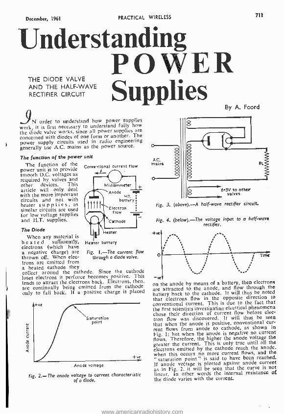
December, 1961 PRACTICAL WIRELESS 711
Understanding POWER Supplies
THE DIODE VALVE AND THE HALF -WAVE RECTIFIER CIRCUIT
iN order to understand how power supplies work, it is first necessary to understand fully how the diode valve works, since all power supplies are concerned with diodes of one form or another. The power supply circuits used in radio engineering generally use A.C. mains as the power source.
The function of the power unit
The function of the power unit is to provide smooth D.C. voltages as required by valves and other devices. This article will only deal with the more important circuits and not with heater supplies, as similar circuits are used for low voltage supplies and H.T. supplies.
The Diode
When any material is heated sufficiently, electrons (which have a negative charge) are thrown off. When elec- trons are emitted from a heated cathode they collect around the cathode. Since the cathode loses electrons it perforce becomes positive. This tends to attract the electrons back. Electrons, then, are continually being emitted from the cathode only to fall back. If a positive charge is placed
Conventional current flow
Milliammeter
Anode T HT.
battery
Electron f low
Cathode
Heater
Heater battery
Fig. I. -The current flow through a diode valve.
Saturation point
+ve
Anode voltage
Fig. 2. -The anode voltage to current characteristic of a diode.
b3 other valves
Fig. 3. (above). -A half -wave rectifier circuit.
Fig. 4. (below). -The voltage input to a half -wave rectifier.
+ve
: o
'. I
: r .
. :
ve, on the anode by means of a battery, then electrons are attracted to the anode, and flow through the battery back to the cathode. It will thus be noted that electrons flow in the opposite direction to conventional current. This is due to the fact that the first scientists investigating electrical phenomena chose their direction of current flow before elec- tron flow was discovered. It will thus be seen that when the anode is positive, conventional cur- rent flows from anode to cathode, as shown in
Fig. 1; but when the anode is negative no current flows. Therefore, the higher the anode voltage the greater the current. This is only true until all the electrons emitted by the cathode reach the anode. when this occurs no more current flows, and the " saturation point " is said to have been reached. If anode voltage is plotted against anode current as in Fig. 2, it will be seen that the curve is not linear. In other words the internal resistance of the diode varies with the current.
www.americanradiohistory.com
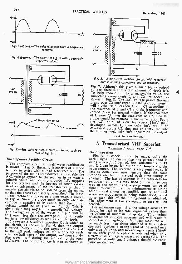
712 PRACTICAL WIRELESS
?ve
Time
-ve Fig. 5 (above). -The voltage output from a half -wave
rectifier.
Fig. 6 (below). -The circuit of Fig. 3 with a reservoir capacitor added.
''`Vokage due to Ct : "' ' .: ......: ..''' ............
O Time
-ve Fig 7. -The voltage output from a circuit, such as
that of Fig. 6.
The half -wave Rectifier Circuit The complete circuit for half wave rectification
is shown in Fig. 3. Basically it consists of a diode rectifier in series with a load resistance RI.. The purpose of the mains transformer is to enable the A.C. voltage applied to the rectifier to be made a suitable value, and also to provide L.T. supplies for the rectifier and the heaters of other valves. Another advantage of the transformer is that it enables the chassis to be isolated from the mains, so that the chassis can safely be earthed. The input to the rectifier is of course a sine wave, a shown in Fig. 4. Since the diode conducts only when its cathode is negative to its anode, then the output voltage would be as given in Fig. 5. This is obviously a long way from a smooth D.C. voltage. The average value of the wave in Fig. 5 will be very much less than the average of Fig. 4, result- ing in a low efficiency as well as a high ripple.
If however a reservoir capacitor Cl is added to the circuit, as shown in Fig. 6, then the output is raised. Very simply, the capacitor is charged to the full peak voltage of the supply by each alternate half wave of the output, and then slowly discharges itself during the interval to the next half wave. The output voltage is then as shown in
December, 1961
8 Fig. 8. -A half-wave rectifier circuit, with reservoir
and smoothing capacitors and an inductor. Fig. 7. Although this gives a much higher output voltage, there is still a fair amount of ripple left. To help reduce this to a reasonable value, the smoothing components L and C2 are added, as shown in Fig. 8. The D.C. voltage passes through L and over C2 unchanged but the A.C. component will divide itself between L and C2 according to the reactance of L and C2 and the frequency con- cerned (50c /s for normal mains). If the reactance of L were 15 times the reactance of C2, then the ripple would be reduced in the same ratio. From the A.C. point of view for every 15mV (say) developed across L, then only lmV would be developed across C2, thus out of 16mV fed into the filter network only ImV appears on the output.
(To be continued)
A Transistorised VHF Superhet (Continued from page 707)
Final Inspection Finally, a check should be made, using the
aerial signal, to ensure that the correct band is being covered. If desired, final adjustments to T1 and C12 can be carried out on the Home and Light programmes. The receiver is very sensitive, so if this is done, one must ensure that the same stations are being received each time tuning is changed. The last adjustment is the ratio detector secondary core; this may need } turn or so one way or the other, using a programme source of signal, to ensure that the minimum -noise tuning point is that giving best audible quality, and that when no modulation is being transmitted, equal noise each side of the tuning -point is obtained. The adjustment is fairly critical; so care will be needed.
For maximum sensitivity, the voltage across C37 should be used to indicate alignment rather than the volume of sound in the speaker. This method of . alignment is more accurate and will result in some loss of bandwidth. Voltages measured will be much less than those obtained with a valve - operated receiver; a strong signal at the aerial may only give #V or so, and weaker signals only 100mV or so, while good reception is obtained when only a very small voltage is measured across C37. The presence of only small voltages should therefore cause no dismay.
www.americanradiohistory.com

December, 1961 PRACTICAL WIRELESS 713
Improving the All -band TRF ADDING AN R.F. STAGE
T was decided to rebuild the Beginner's T.R.F., described by F. G. Rayer in the March and April 1959 issue, making a few improvements and adding an R.F. stage. The final result was most satisfactory with extremely good sensi- tivity, selectivity, volume and tone.
NEW STAGE
AERIAL
NOTE: SI AND S2 SHOWN IN MEDIUM
WAVEBAND POSITION
By J. L. Wain
The first valve acts as the R.F. amplifier. A
2 -pole 5 -way switch enables the aerials to be tuned or untuned. VRI controls R.F. gain. The signal is fed via an R.F. transformer (detector coil) to the second valve, which acts as detector (as before). An EF39 valve was used as Vl.
RB 47k 0000 CHOKE
C20 8yF
PS 1006
MAIN TRANSFOS RMFI
8
VRI 1004 RE GAIN
52 DETECTOR
IANDSWITCH
S2 ó SI RF
RAND- SWITCH
DETECTOR COILS VR2 5Ok
REACTION
aO 0OIHF
OUUT TRATPNSF'NTR
SOpF 8
C3 ONHF
R4 100[1
ó o I2c2O.1yF 543 0.5M
VOLUME PILOT
MF
oI F
_ CS INF
1 CB1OpF
AMP INPUT JACK
AERIAL COILS V2
RADIO SWITCH
S4
Fig. I. -The complete circuit diagram of the improved receiver.
PHONES
AMP SW TCH
To To V4 To V4 To V4 Choke pin 3 pin 8 pin 5
To V2 To V2 To V3 pin4 pin3 To
pin 8 and VR2 and C9 ' HT+ slider
6.3V
MAINS SWITCH
SS
AC MAINS
To HT +and Detector ToV1 TTV1 To -
coils pin 4 pin 8 Sla
To Phones To VR4 To V3
socket slider pin 3 To VR3 To To VRI and Amp VR2 slider Method of securing
Input jack large components
Fig. 2. -The wiring of the components on the large group -board under the chassis.
www.americanradiohistory.com
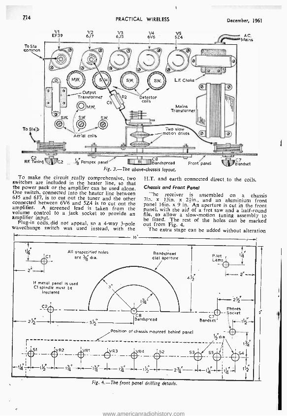
714
To Sta Common
To S1a,b
PRACTICAL WIRELESS
V1 V V3 6J7 6J5 6V6 5Z4
December, 1961
A.C. Mains
r S Aerial coils
L.F. Choke
Mains Transformer
/A \\\ C2
RE Tuning
_ %g Perspex panel iIIlll1,71111II Bandspread
Fig. 3. -The above -chassis layout.
To make the circuit really comprehensive, two switches are included in the heater line, so that the power pack or the amplifier can be used alone. One switch, connected into the heater line between 6J5 and 6J7, is to cut out the tuner and the other connected between 6V6 and 5Z4 is to cut out the amplifier. A screened lead is taken from the volume control to a jack socket to provide an amplifier input.
Plug -in coils, did not appeal, so a 4 -way 3 -pole wavechange switch was used instead, with the
All unspecified holes are ajé di a.
16'
Front panel C7 Bandset
H.T. and earth connected direct to the coils. Chassis and Front Panel
-he receiver is assembled on a chassis lin. x 13in. x 2 }in., and an aluminium front panel 16in. x 9 in. An aperture is cut in the front panel, with the aid of a fret saw and a half -round file, to allow a slow -motion tuning assembly to be fitted. The rest of the holes can be marked out from Fig. 4.
The extra stage can be added without alteration
Bandspread dial aperture
If metal panel is used Ct spindle must be
insulated
C2
a,z
C8 Bandspread
Position of chassis mounted behind panel
51 VR2 VR1 1VR3
Pilot Lamp
CY Bandset
0 r L
Phones Socket
If-1
34°
Fig. 4. -The front panel drilling details.
www.americanradiohistory.com
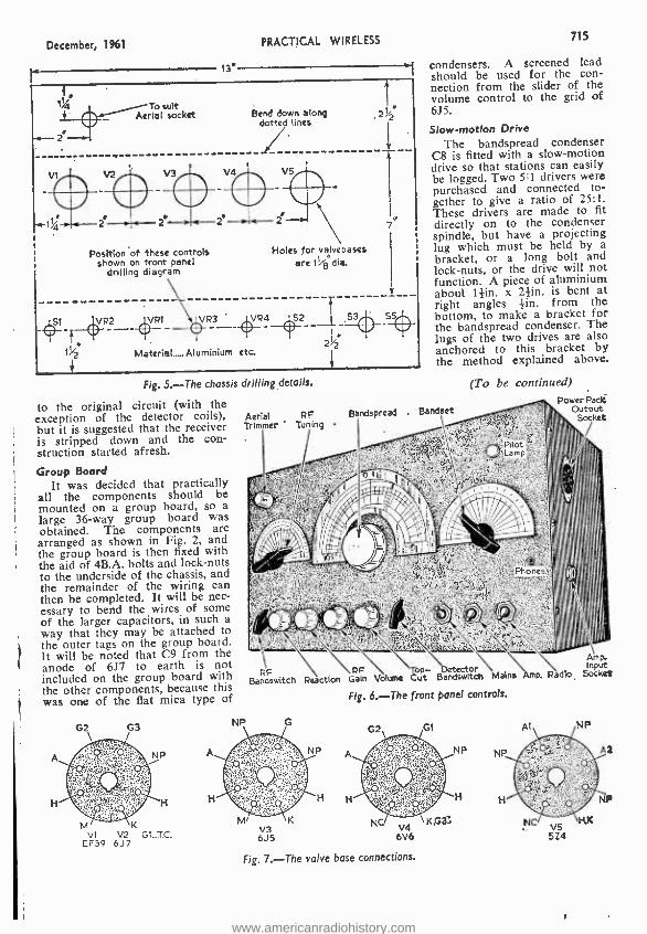
December, 1961
r 2
,-
To suit Aerial socket Bend down along
dotted lines
PRACTICAL WIRELESS 715
13' j condensers. A screened lead should be used for the con- nection from the slider of the volume control to the grid of 675. 2%Z
V4 VS
Position of these controls shown on front panel
drilling diagram
Holes for valvebases are 11/e dia.
St VR2 VRi VR3 VR4 52 -t - ---4 t%2 Material Aluminium etc.
7
Slow- motion Drive The bandspread condenser
C8 is fitted with a slow- motion drive so that stations can easily be logged. Two 5:1 drivers were purchased and connected to- gether to give a ratio of 25:1. These drivers are made to fit directly on to the condenser spindle, but have a projecting lug which must be held by a bracket, or a long bolt and lock -nuts, or the drive will not function. A piece of aluminium about lZin. x 24in. is bent at right angles sin. from the bottom, to make a bracket for the bandspread condenser. The lugs of the two drives are also anchored to this bracket by the method explained above.
Fig. 5. -The chassis drilling details.
to the original circuit (with the exception of the detector coils), Aerial PP Bandsprcad . Bandset
but it is suggested that the receiver Trimmer ' Tuning
is stripped down and the con- struction started afresh.
Group Board ¢ tJ `- It was decided that practically
all the components should be mounted on a group board, so a large 36 -way group board was obtained. The components are arranged as shown in Fig. 2, and the group board is then fixed with the aid of 4B.A. bolts and lock -nuts to the underside of the chassis, and the remainder of the wiring can then be completed. It will be nec- essary to bend the wires of some of the larger capacitors, in such a way that they may be attached to the outer tags on the group board. It will be noted that C9 from the Amp.
of 6J7 to earth is not Detector \ Ap . RF RP Top- DDetector
included on the group board with Bandswitch Reaction Gain Volume Cut Bandswitcn Mains Amp. Radio Socket
the other components, because this Fig. 6. -The front panel controls.
was one of the flat mica type of g P
(To be continued) Power Pack
output Socket
G2 G3
NP
M K
VI V2 Gt...TC. EF39 6J7
Fig. 7. -The valve base connections.
www.americanradiohistory.com

Practical Wireless I ,Z The P.W. 'Citizen' is the third blueprint design in our progressive series and has been especially designed for successful construction by those who first began building radio sets with 'Tutor' In the October issue.
Preparing the Group Board Refer to the Blueprint. Notice the numbering
of the tags; as in the Mini -Amp, it is a good idea to stick paper strips on to the group board so that there is no confusion when wiring up by the numbers (see Fig. 2 on the " Mini -Amp " Blue- print). The numbering shown is when the strip is viewed with the soldering tags on top. Tags 17 and 35 are carefully removed by drilling partly through (on the rivet side of the board) with a min. drill. The tags are removed so that the undamaged holes in the paxolin may take two small bolts which will eventually hold the tuning capacitor on to the board (see Figs 6 and 7). The spacing of the holes is already correct.
The hole " D " in Fig. 3 is now enlarged to take the gin. boss of the wave -change switch (SI), and two more holes are drilled each side of holes F and G as shown in Fig. 3. The position of these is important and therefore a full -size template is given in Fig. 15 (above). Two more holes are drilled near to tags 10 and 28. The oscillator coil should now be tried for a fit (the fixing tags go through the two outside holes). Do not attempt to force it into position for it may be damaged. If the fit is satisfactory, mount the oscillator coil from the rivet side of the group board and solder the fixing tags to tags 10 and 28 (see Fig. 4), making
sure that pin 1 (near the red spot on the base - Fig. 8) lies near tag 10 and not tag 27.
fixing the Tuning Capacitor and Ware -thong. Switch
The wave- change switch is mounted with the switch on the tag side of the board and the spindle on the rivet side. It is arranged so that the connec- tions are in a similar position to those in Fig. 4 and the nut is then tightened up using a non -slip washer beneath it. It may be necessary to flatten out tags 4 to 8 and 22 to 26 as shown in Fig. 3, tag 8 being soldered directly, or wired, to the casing of the switch assembly (see Fig. 4). The variable capacitor should now be examined carefully. It must have a metal screen between the two ganged sections and be fitted with small trim- ming condensers on the back (Cla and C2a- Fig. 7). The smaller section is C2 and the larger .section is Cl. Although three fixing holes are provided at the front of this condenser, these are not used. Two small threaded holes will be found on the back of the condenser and these are used for mounting. Bolts are fitted with solder tags and passed through holes 17 and 37 (Fig. 4) from the tag side of the strip. Two hin. thick washers are fitted on the rivet side of the strip and the bolts are then screwed into the holes on the condenser -the washers, in fact, space the con- denser away from the board (see Fig. 7). Be care- ful that the bolts are not too long or they will badly damage the stators of the condensers. The mounted condenser will appear as in Fig. 7. Note that both the oscillator coil and tuning condenser
must be firmly fixed for good stability in operation. Wiring in the Resistors and Fixed Condensen
Wire in R3 between tag 14 and tag 1 of the oscillator coil, using as little heat as pos- sible, but making a good joint. Make sure that tag 1 is in the position shown in Fig. 4. Wire R2 from tag 2 to tag 20, join 20 to 21 and connect R1 from _21 to 3_ (Fig. 4). Wire C7 between tags 36 and 33 making the connections as short as possible. Fix C5, again with the leads as short as pos- sible, between tag C of S16 and tag 29. Attach C3 between tags A and B of S16. Attach C6 across R3; i.e. from tag 14 to pin 1 on the oscillator coil. The condenser C4 is then soldered on the other side of the board to rivets 2 and 20 as shown in Fig. 6. Wire tag 28 to coil pin 4, and tag 9 to coil pin 6. Join tag 33 to tag 29 with covered wire and then tag 29 to coil pin 3. Solder one of the soldering tags under the tuning condenser fixing bolts to tag 18 (see Fig. 4). Connect tag A of S16 to tag 8. Abore- chassis Wiring
Connect a red wire between tags 2, 8, 10, 14 and 18 as in Fig. 6. This is what
The frequency changer unit
www.americanradiohistory.com

EN By J. Bisset
THE THIRD OF OUR
PROGRESSIVE SERIES
OF BLUEPRINT
DESIGNS
would normally be called " Earth " or "Chassis ", and is in this unit, battery positive.
Refer to Figs. 6 and 16 and note the wire con- necting tag 11 and the stator of Cl, the shape of this lead is quite important to prevent unwanted feedback.
Refer to Fig. 7 and connect a short lead from tag 36 to the stator of the oscillator tuning section Cl.
Adding the Transistor
Check the wiring carefully. Put sleeving on the leads of the transistor (TRI) and then quickly solder them as follows (using a heat shunt as on page 509 of the October issue): -the base (centre lead) to tag A of Sla as shown in Fig 5; the col- lector (nearest the white spot lead) to coil pin 5
and the emitter (remaining lead) to coil pin 2. -
Position the transistor cenveniently but without bending the leads nearer than -tin. to the bottom flange.
Adding the Aerial
The aerial is made up of three parts (see Fig. 17).
The long and medium wave coils are separate and may be slid along the ferrite rod to obtain optimum results. Two types are available (both under the part number RAW2). The type having thin leads from the actual coils connected to a
circular tag strip in the middle is not the best for this design as the movement of the coils along the strip is restricted -the type having tag rings on
each coil is to be preferred. The coils are provided with coloured tags. If
you have a meter, check that there is a connection between the sets of colours: -blue and yellow; black and yellow; white and green; white and red. (If not, the coil unit is faulty.) Connect leads up about 8in. long to the coil tags using the same coloured wires as the tag colours if possible, make sure that in soldering to the coil tags, the thin wires of the coils themselves are not detached.
The I.F. amplifier
Now test, the ends of the coloured leads u detailed above.
The leads should be held together in places with Sellotape or insulating tape, but should not be twisted together. The ends are connected to the group board unit as follows (see Fig. 5): -red to
Fixing tag groove 9
60° between pins
LE can
58 dia 3/8 dia. coil base pitch circle
Homemade adjusting tool (celluloid)
Fig. 15 (left). -The layout of the coil pins (actual size).
Fig. 18 (right). -A simple trimming tool for the
oscillator and I.F. coils; the total must be made oe
shown so that the shank will fit inside the cores of the coils.
NlaveetAarh+ge
SI
Aerial
L3
ca
l7 2
V 4_l_ . _ _ .. .:1
t sl
u e
Oscillator tuning
Fig. I6. -The position of the wire from CI to tag II in the frequency changer section; this wire must be
arranged exactly as shown to avoid the lower section of the variable capacitor gang (C2).
www.americanradiohistory.com
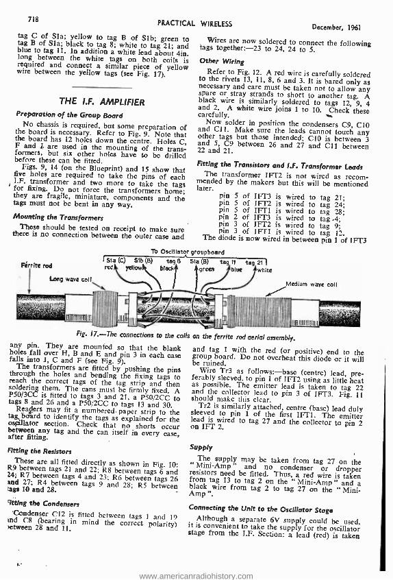
718 PRACTICAL WIRELESS
tag C of Sla; yellow to tag B of Slb; green to tag B of Sla; black to tag 8; white to tag 21; and blue to tag 11. In addition a white lead about 4in. long between the white tags on both coils is required and connect a similar piece of yellow wire between the yellow tags (see Fig. 17).
THE I.F. AMPLIFIER Preparation of the Group Board
No chassis is required, but some preparation of the board is necessary. Refer to Fig. 9. Note that the board has 12 holes down the centre. Holes C, F and J are used in the mounting of the trans- formers, but six other holes have to be drilled before these can be fitted. Figs. 9, 14 (on the Blueprint) and 15 show that five holes are required to take the pins of each I.F. transformer and two more to take the tags for fixing. Do not force the transformers home; they are fragile, miniature, components and the tags must not be bent in any way.
Mounting the Transformers These should be tested on receipt to make sure there is no connection between the outer case and
Fírrite rod
Long wave coif
December, 1961
Wires are now soldered to connect the following tags together:-23 to 24, 24 to 5.
Other Wiring Refer to Fig. 12. A red wire is carefully soldered to the rivets 13, 11, 8, 6 and 3. It is bared only as necessary and care must be taken not to allow any spare or stray strands to short to another tag. A black wire is similarly soldered to tags 12, 9, 4 and 2. A white wire joins 1 to 10. Check these carefully. Now solder in position the condensers C9, C10 and CI1. Make sure the leads cannot touch any other tags but those intended; C10 is between 3 and 5, C9 between 26 and 27 and C1I between 22 and 21.
Fitting the Transistors and I.F. Transformer Leads The transformer IFT2 is not wired as recom- mended by the makers but this will be mentioned later.
pin 5 of IFT3 is pin 5 of IFT2 is pin 5 of IFTI is pin 2 of IFT3 is pin 3 of IFT2 is pin 3 of IFtI is
The diode is now wired
To Oscillator groupbosrd Sla (C) Slb (B) tag 8 51a (B) ta 11 tag 21 redk yellow R black+ 4green (blue white
wired to tag 21; wired to tag 24; wired to tag 28; wired to tag .4; wired to tag 9; wired to tag 12.
in between pin 1 of IFT3
Medium wage coil
Flg. 17 -The connections to the colis any pin. They are mounted so that the blank boles fall over H, B and E and pin 3 in each case falls into J, C and F (see Fig. 9). The transformers are fitted by pushing the pins through the holes and bending the fixing tags to reach the correct tags of the tag strip and then soldering them. The cans must be firmly fixed. A P50 /3CC is fitted to tags 3 and 21, a P50 /2CC to tags 8 and 26 and a P50 /2CC to tags 13 and 30. Rears may fit a numbered paper strip to the tag, board to identify the tags as explained for the oscillator section. Check that no shorts occur between any tag and the can itself in every case, after fitting.
Fitting the Resistors These are all fitted directly as shown in Fig. 10: R9 between tags 21 and 22; R8 between tags 6 and M; R7 between tags 4 and 23; R6 between tags 26 and 27; R4 between tags 9 and 28; R5 between tags 10 and 28.
Wring the Condensers Condenser C12 is fitted between tags 1 and 19 and C8 (bearing in mind the correct polarity) >etween 28 and 11.
ti
on the ferrite rod aer al assembly.
and tag 1 with the red (or positive) end to the group board. Do not overheat this diode or it will be ruined. Wire Tr3 as follows: -base (centre) lead, pre- ferably sleeved, to pin 1 of IFT2 using as little heat as possible. The emitter lead is taken to tag 22 and the collector lead to pin 3 of IFT3. Fig. 11 should make this clear. Tr2 is similarly attached, centre (base) lead duly sleeved to pin 1 of the first IFT1. The emitter lead is wired to tag 27 and the collector to pin 2 on IFT 2.
Supply
The supply may be taken from tag 27 on the " Mini -Amp " and no condenser or dropper resistors need be fitted. Thus, a red wire is taken from tag 13 to tag 2 on the " Mini -Amp " and a black wire from tag 2 to tag 27 on the " Mini - Amp".
Connecting the Unit to the Oscillator Stage Although a separate 6V supply could be used, it is convenient to take the supply for the oscillator stage from the I.F. Section: a lead (red) is taken
www.americanradiohistory.com
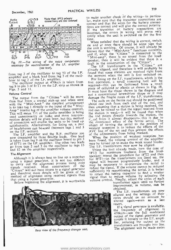
December, 1961 PRACTICAL WIRELESS 719
to make another check of the wiring -in particu- lar, make sure that the transistor connections are correct and that the wires for the battery connec- tions are correct and will give the correct polarity. If the transistor or battery connections are incorrect, the errors in wiring will prove very costly when the unit is switched on for the first
time. When satisfied that the wiring is correct, switch
on and at once there should be some sign that the unit is working. Of course, it will already be known that the " Mini -Amp " functions correctly, and if, when the "Citizen " is connected to the " Mini -amp ", there is no sound from the loud- speaker, then it will be evident that there is a fault in the construction of the "Citizen ".
The I.F. transformers in the "Citizen " are already aligned, and therefore it will probably be found that some stations are received right from the moment when the unit is first switched on.
For lining up the 1.F. transformers, which is the first operation, a small trimming tool will be
required -this can be fashioned from a small piece of celluloid or plastic as shown in Fig. 18.
It must have the shape shown in the diagram and not a conventional screwdriver shape or it may damage the fragile cores of the I.F. transformers.
The coils on the ferrite rod should be positioned about one inch from each end of the rod, and then assuming that a station is being received, the rod can be turned so that the signal received from the station is weak -it will be found that when the rod points directly towards the station, the
s`._aal from it almost disappears -this is due to
the directional effect of the ferrite aerial. The object of turning the aerial to the position of weakest reception is to reduce the effects of the
AVC line of the set and thus prevent the effects
of the adjustments from being masked. When the position of weakest reception has
been found, the volume control of the amplifier may be turned up to make the weak sound louder. The I.F. transformers may now be aligned.
Using the tool already made, turn the core of
IFT3 for maximum loudness from the loud-
speaker; repeat the procedure for IFT2 and then
for IFT1 -as the transformers are lined up, the
signal will become progressively louder, and it
may be necessary to re- orientate the aerial to
reduce the signal. If the volume cannot be reduced
sufficiently by repositioning the aerial, it is better to rotate the tuning capacitor to find a weaker
signal than to reduce volume by adjusting the
volume control. Finally, adjust the cores of each transformer again until no further improvement, in volume, can be obtained.
The I.F. transformers are now aligned and the settings of their cores should on no account be altered again -even as a last resort.
If a signal generator is available, the frequency of alignment is
470kc /s -use the full modulated output of the signal generator and couple it loosely to the I.F. ampli- fier, reducing the output as the transformers are brought into line. The alignment will be made easier
Tr3 Note that ará rrowmreversed
e 8 9 13 18
36 19 21 22 28 2 X30 -
1F 3 9 C13 R 8p k 6F Tr2 12k
Fig. 19. -The wiring of the extra components
necessary for neutralisation of the I.F. amplifier (see text).
from tag 2 of the oscillator to tag 13 of the I.F. amplifier and a black lead from tag 3 of the oscil- lator to tag 2 of the I.F. amplifier.
The oscillator output at 470kc /s is taken from tag 9 to pin 3 of IFT1 on the I.F. strip as shown in
Figs. S and 11.
Volume Control The output from the "Citizen " will be more
than that from a crystal pick -up and when used with the " Mini-Amp" the simplest arrangement is to take tag 1 directly to the input of the " Mini - Amp " (centre tag of the amplifier volume control). This will mean Trl of the audio amplifier is being used unnecessarily on radio and more intercon- nection details will be given later, but this method of connection will enable the units to be lined up
satisfactorily. Alternatively, for lining up, a pair of headphones can be.used (between tags 1 and 3
on the I.F. section). The I.F. amplifier and the R.F. oscillator are
now connected by three flexible leads. One lead is taken from tag 9 on the oscillator board to pin 3
of IFT1 on the I.F. amplifier. The other two leads go from tags 2 and 3 on the oscillator to tags 13
and 12 on the amplifier respectively.
The Alignment
Although it is always best to line up a superhet using a signal generator, it is not too difficult to carry out the alignment process using only signals received. Most constructors of the "Citizen" will not have access to a signal generator and therefore more details will be given of the method of alignment using received signals than that using a signal generator.
Before beginning the alignment, it is worthwhile
Rear view of the frequency changer unit.
www.americanradiohistory.com

720 PRACTICAL WIRELESS December, 1961 if a large condenser -0.1µF to 0.5µF is tem- porarily wired across Cl. R.F. Alignment
If a condenser has been used across CI, remove it and switch to medium waves (the anticlockwise position of SI, viewed from the rivet side of the board). When the tuning capacitor is rotated, stations should be received, the number depending upon the state of the circuit and the time of day. The alignment is carried out using two known stations -at night time, Radio Luxembourg and the Third Programme are suggested because these fall at the extremes of the tuning coverage. Other stations may be used, but one must be at the high frequency (short wavelength) end of the medium waveband and the other at the low frequency (long wavelength) end. Radio Luxem- bourg is specified above as it is broadcast on the highest frequency which it will be required to receive. Turn the tuning condenser almost to minimum capacity- almost to its fully open position. Screw up the
and C2atrimmers ghtly and ithenmunsgcrew denser (Cla
one turn. Now adjust the core of the oscillator coil until the station chosen at the high frequency end of the waveband is received. Then turn the tuning condenser to a position where the vanes
the trimmer Cla for best. results. Set the tuning condenser to the station at the low frequency end of the waveband and adjust the position of the medium wave coil on the ferrite aerial for best results -the medium wave coil is the long, single layer coil, not the pile -wound coil. Repeat these two adjustments until no further improvement is obtained. It should be noted that this latter part of the R.F. alignment should be carried out when the unit is housed in position in the case intended for it. Of course, the procedure may be carried out twice, once with the unit out of the case and finally with the unit in position to obtain optimum results. When the constructor is satisfied that the results are satisfactory, the medium wave coil may be sealed to the ferrite rod using Balsa cement or Durofix, taking care to keep the adhesive away from the wire of the actual coil.
The long wave alignment is simple and consists of tuning to the long wave Light Programme and adjusting the position of the long wave coil on the ferrite rod for loudest reception. This coil may also be sealed in position on the ferrite rod when results are satisfactory. Neutralisation
Transistors, being similar to triode valves, have appreciable self feedback which sometimes has to be neutralised. The I.F. amplifier described has been built in three prototypes and no troubles were experienced when IFT2 was wired as shown (Figs. 2 and 4).
Should any reader have trouble over " whistles ", this is a sign of poor alignment, or a badly wired oscillator section, or even that neutralisation is required. Fortu- nately the makers of the I.F. trans- formers have evolved an effective neutralisation system: connect a capacitor in series
resistor 156 of fFTT2 and pin 1 of IFT1 on the I.F. amplifier. Connect also a 3.9k resistor and an 18pF (1%) capacitor in series between pin 1 of IFT2 and pin 1 of IFT3 (i.e. to the black end of the diode). Also, reverse the connections to pins 2 and 3 of IFT2 (see Figs. 11 and 19).
(To be continued)
Front view of the frequency changer unit.. are about three- quarter closed -about 30° from being fully enmeshed. It is important to use a knob on the tuning condenser spindle for this
settings operation so that the osen s ations can be foundrep
used edlyr A
the two make- shift cardboard dial could be fastened to the front of the tuning condenser so that pencil marks may be made corresponding to the stations. When the position has been decided for the Third Programme adjust the oscillator coil core (L3) until the signal is heard at the desired point. Return to the other station at the other end of the waveband and adjust the trimmer C2a until the station is at the desired point. Return to the Third Programme setting -do not tune to the signal which will now be at a different position, but return the tuning condenser to the setting marked previously. Adjust the oscillator coil core to return the signal to the desired point. Return the tuning condenser to the other setting and readjust the trimmer C2a until the signal is heard again. Repeat these adjustments until no further improvement is obtained and until both stations come in at the marked points. The oscillator alignment is then completed.
Next, turn the tuning condenser to the station at the high frequency end of the waveband. Adjust
Cable Contract THE Republic of Indonesia has placed a contract with Associated Electrical Industries Ltd. for the supply of telephone cable. Since negotiations for this order began, cable manufacture within AEI has been rationalised and the cable will be manu- factured by Telephone Cables Ltd., of Dagenham, an AEI subsidiary owned jointly with Enfield Cables Ltd.
The cables will be of the paper insulated under- ground and plastic insulated underground type and delivery will take place over a period of five years. The cable is being supplied to the Ministry of Land Transport, Posts, Tele- communications and Tourism.
www.americanradiohistory.com

December, 1961 PRACTICAL WIRELESS 721
FAULTS IN VHF/F.M. R EC F I V E R S 2 The I.F. Stages
By G. J. King that they are as close as possible to the circuit which they are required to switch, and in this way
(Continued from page the connecting leads can be kept as short as pos-
607 of the November issue) sible. This point should be remembered during
N Part 1 of this series we considered various the course of servicing. Another popular arrange -
faults that are likely rro develop in the VHF tuner ment is the Plessey switch constructed of two
unit of an F.M.-only receiver or tuner or In the long, narrow sections of low -loss insulating
VHF tuner of a composite A.M. /F.M. receiver. material. One section is fixed to the frame and
In the latter type of receiver, a VHF tuner fault the other is in the form of a slider which can
is unlikely to affect the performance on A.M., so move a limited distance along the fixed section.
that while an A.M. /F.M. set may function per- Switch contacts are situated along the fixed sec -
fectly normally on the medium frequencies, it tion,s hi the carries
h the fixed contacts contact
ct to may be totally swdead or exhibit a fault symptom
provide the required switching arrangements. only when switched to F.M. In this event. of P
course, the VHF tuner should first be investigated, Dual I.F. Transformers but it should also be noted that similar trouble could occur owing to a fault developing in some In all composite receivers, the I.F. stages are
other part of the set, as described in this article. coupled by two I.F. transformers connected in
series. The primary winding of the F.M. I.F.
Switching Arrangements transformer is always connected to the anode of
In Fig. 8 is shown the two I.F. stages of a corn- the valve, while the secondary winding of the
posite A.M. /F.M. receiver. The heptode section of same transformer is connected to the grid of the
V2 functions as the first I.F. amplifier and when following valve. as shown by IFT2 in Fig. 8. The
the receiver is switched to F.M., which is the A.M. I.F. transformer windings are then connected
position it is switched to in the circuit, the tuner in series. The A.M. I.F. is usually 470kc /s, while
I.F. signal is applied, via screened cable, to the F.M.1.F. is allowsMc this /s method
large connection,
difference
heptode made
grid through part
The VHF since the impedance of the A.M. I.F. transformer
tuner is made operative by a part switch S4
which applies H.T. +2 to the tuner frequency is very low at 10.7Me /s and it does not affect the
changer, while another part of the same switch F.M. I.F. coupling. Although there are separate
removes H.T. from the triode section of V2, which troansappear ormstowhen so
ingñ heachansis screening
this
noted
may
acts as local oscillator on A.M. It will also be non is to
be both transformers.
noted that on F.M. a part of S2 short -circuits the A.M. AGC line. Low Gain on A.M.
These switches sometimes give trouble and can cause total failure or intermittent operation of A.M. It sometimes happens that the sensitivity of the
or F.M. For example, it there is a poor connection receiver falls off badly on A.M. while remaining
in S4, H.T. may not get through to the VHF fairly normal on F.M. Several cases of this symp-
tuner The set would thus work perfectly on A.M. tom were caused by alteration in value of one of
but not at all on F.M. Since H.T. is being the fixed tuning capacitors across the windings
switched, sparking occurs between the contacts of 0-2 A.M. I.F. transformers. These capacitors
and after a while this may produce an intermit- are usually installed inside the screening cans.
tent connection which would be likely to cause Each core in the I.F. transformer should peak,
interference effects on F.M., possibly accompanied but if this fails to happen with one core and it
by tuning drift caused by variation of the H.T. seems that the sensitivity could be improved by
voltage applied to the VHF frequency- changer screwing the core farther into the former than
valve. is, in fact, possible, then the fixed capacitor across the associated winding will almost certainly have
Effect on A.M. decreased in value.
Trouble of a like nature may also result on Replacement should be made with components
A.M. due to high resistance switch contacts in of identical type and value and the A.M. I.F. stages
the A.M. local oscillator circuit. This trouble should afterwards be realigned, preferably with -
rarely occurs in the ordinary wavechange switch- a signal generator and output meter, but failing
ing, however, possibly because there is little or that, by peaking the cores on the local station.
no H.T. current flowing through the switch A.G.G. Troubles contacts. AGC
Various types of switch are used in A.M. /F.M. aecA.M.' However awhlie the receivers; some manufacturers favour the ordinary the normal manner on
rotary type made up of several units on a corn- set is switched to F.M., the A.M. AGC line is
mon spindle. The switch units are positioned so usually shorted to chassis, and if there is F.M.
www.americanradiohistory.com

722 PRACTICAL WIRELESS December, 1961 AGC then this is switched into circuit. F.M. AGC is not always used, and rarely used when the circuit features a phase discriminator detec- tor. Where a ratio detector is used, an arrange- ment similar to that shown in Fig. 8 is used. Here the F.M. AGC voltage is derived from across the ratio detector load resistor (to be dealt with in a subsequent article) and fed to the sup- pressor grid of the second I.F. valve, V3. In the event of a very strong signal, a high negative voltage will appear across the ratio detector load and this is used to reduce the gain of the I.F. stage accordingly.
This is a very simple circuit and rarely causes trouble. Nevertheless, should excessive fading and 1¢+ To TUNER
RF AMPLIFIER R4 HT+ TO TUNER
FREQUENCY -CHANGER
eu 4f R;AI.
es 300pF
460 KC/S LF
TRAF
-d
L7 Le
10k
R7 IOk 17w
PS 39
attributable to failure or low emission of the triode section, even though the heptode section works normally as an I.F. amplifier on F.M. A quick check for oscillator operation is to break the connection between the switch side of R9 and insert a D.C. milliammeter, with the negative ter- minal to the resistor. If the oscillator is working there will be a marked change of current when a short is applied across C26, the oscillator section of the tuning gang.
Noise on A.M. Intermittent noise which varies in intensity has often been proved to be caused by a fault in the oscillator anode resistor R6. It is, in fact, possible
RII CO036
05yF I.AM 1 FT,1
HT +1
H.T.+ 2
SP13 R9 2
100k
SCREENED NEEARD
06A 5pF
VHF I.F.T.2
125 5OpF
LIS LIE C2B
3-30pF
3&p, O.C285yF
53A
0.005 HF
GANGED
C34 3-3OpF C35
22^PF
EARTH P43
Fig. 8. -The I.F. stages of a typical A.M. /F.M. receiver distortion occur as the result of passing aircraft, for instance, the AGC feed from the ratio detector should be checked, as also should the associated components, such as C41 and switch S2. It has been known for poor insulation to develop on the switch, between two separate contacts, and allow an H.T. voltage to appear in the AGC circuit, thereby completely disturbing the normal operation. Similar trouble sometimes takes place on the printed wiring board, especially after a set has been in service for a number of years and excessive dust has been allowed to accumulate on the wiring.
A.M. Operation When a composite receiver is switched to A.M., the VHF tuner is no longer used, and the first I.F. amplifier (e.g., V2) is changed to a conven- tional A.M. frequency changer. The triode sec- tion is connected to H.T. and operates as the local oscillator. Failure on A.M. but not on F.M. is often
OooSy,FT F.M AGlC
NEGATIVE FEEDBACK AM A&
to observe the effect on a milliammeter connected as described above by the current fluctuating in sympathy with the crackles and noise. This should lead immediately to replacement of the resistor. However, if this does not clear the trouble, and there is no sign of the noise on F.M., C25 and C27 should also be replaced. As already intimated, noise may be generated
in the oscillator switch, S4, and provided the contacts are not badly burned, the application of a good quality switch cleaner will solve the problem.
Printed Circuits Most A.M. /F.M. receivers use printed circuits which themselves sometimes introduce faults. When soldering parts into such a circuit, extreme caution should be observed to avoid overheating with the soldering iron. In the original type of printed circuit, undue heat results in the foil be- coming loose from the board. This trouble may
(Continued on page 729)
www.americanradiohistory.com

December, 1961 PRACTICAL WIRELESS 723
if ETURN -OF -POST SERVICE We offer a really efficient Mall Order Service on all items stocked. All cash orders are dealt with on the day of receipt.
* Hire purchase orders are subject to slight delay but this is kept to the absolute minimum
ASON FM TUNER KITS LOUDSPEAKERS.
GOODMANS: Axiom 110 loin. £5.2.0: Axiom 112 101n.
£8.14.0; Axiette 8ín, £6.16.0; Axiom 30012ín. £11.5.9: Axiom
Tweeter l 4.Ó: CX 500 CrossOOver 1.19 0129' Trebax
WHITELEY: HF 1016 loin. £8.4.0: HF 1012 loin. £5.2.6: HF810 Bin. £7.0.9; TRIS 8111. £8.10.0; TIO Tweeter £4.8.3; T359
Tweeter Cross-over £1.11.8; CXLa00
Cross-over unit H.P. H.P ms available.
TAPE ACCESSORIES WEARITE DE- FLUXER. For the regular de- magnetising of Tape Heads. 50 /- post 1 /-. BIB TAPE SPLICER. 18 /6. post 9d. EMI TAPE ACCESSORY KIT. 37/6. post 1 / -.
Rao deat nchepseo te 6 to 10
Kos. d l inches per TAPE. Tones
Postage
TRANSISTORS MULLARD. Reduced prices. Current production types. not rejects. All in makers' boxes.
Match11/-; irs8 % 101-:
C78. 81 - OC81, SI -IÓ017Ó, 1a 6; OCí71.014/8 Postage 3d. on each transistor.
AMPLIFIER KITS po We 3-3 lMollard
of all 3 components
Pre-amp, mp tMul anMullard Stereo. Mixer, GEC 912 Plus. Fully detailed list on any of
these sent upon request. Instruction gl9/5. Mullard Circuits "rcuíts for AudioAmpif e s ". EC 12, 4/8. All post tree.
STEREO COMPONENTS Morganite ganged potentiometers as specified for the Mullard circuits. Log /Anti-Log, 500k. 1 meg., 2 meg. Log /Log. 50k.
250k, 1 meg. 2 meg. Lin /Lin. 250k. 500 k. 1 meg. 2 meg. All 10/8 each. Pick -up cartridges. B.S.R. TOSS £2.5.11. Turn-over
Millard Stereo Designs is 78 records. of all components for
"P.W. TUTOR" Everything in stock. Stage 1 including brand new light- weight headphones. 39/6. Less headphones. 23/8. Stage 2 191 -: Stage 3
21/6. 13.6..
Stage ll post free.
All Please note that the
Less
Clips and cement not included. All items available separately -send for list.
"P.W. MINI -AMP" Complete
All ikit parts
for amplifier separately, en or list.
P2í585.
"P.W. TUNER UNIT" Send for parts list.
GRAMOPHONE EQUIPMENT Hire Purchase ALL LATEST MODELS
ALL POST FREE RECORD Cae ÁPGERS
Deposit Mthly /Pmts.
COLLARO C60 (GP67 PV) £8.5.0 £1.13.0 12 of 33/- GARRARD RC210 (GC8PU) £10.6.0 £2. 2.0 12 of 15/4 B.S.R. UA14 (TC8 PU) 07.19.8 £1.12.6 12 of 12/3 B.S.R. ÚA14 Monarch
(TCBS Stereo /LP /78) £8.19.6 £1.16.8 12 of 13/7 SINGLE RECORD PLAYERS
GARRARD TA (GCB PU) ., 28.10.0 £1.14.0 12 of 13/- B.S.R. TUS (TC8 PU).. £4.12.6 £1. 6.6 3 of £1.5.4 E.M.I.(Aoos Stereo /Mono
PU).. .
£6.15.0 £1. 7.0 12 of 10/6 TRANSCRIPTION UNITS
GARRARD 4HF (GCB PU) £18.18.0 03.16.0 12 of £1.7.8 PHILIPS AG10t6 .. £14. 3.8 £2.17.6 12 of £1.0.9
Graanmophone above t Lisupplied o etails
reg working. See our
MAINS TRANSFORMERS GILSON: W0741AB. 63/ -, post tree; W0839, 48/9, post 2/9; PARTRIDGE: 14300 /110, 72/ -, post free; P4132, 78/6, post free; P3877. 25.12.0, post free; P4013, 801 , post free. ELSTONE: MT/MU, 8 / , post
3/3; 3.
MDT3 /M. 35/-, pest 3/ -.
OUTPUT TRANSFORMERS GILSON:
2/6. W0892. 02 3 post free; W0767 27/- Post 11018R, 55/8.
PARTRIDGE: P3687. 52 /6, post 2/6; P4014. 98/6, Post free; P4131, 601 -, post free; P3591A. 99/ -, post free; P5202, P5203, 95/ , post free. PARMEKO: P2641. 28 / -, Post 2/ -.
TERMS OF BUSINESS Cash with order or C.O.D. We charge C.O.D. orders as follows. Up to £3. minimum of 3/2. Over £3 and under 25. 1/6. Over £5 and under £10, 1 /8. Over £10, no charge. Postage extra on CASH orders under £3 except where stated. Postage extra on Overseas orders irrespective of price.
WATTS RADIO (MAIL ORDER) LTD.
s avvailable. Kits are tcomplete with all valves and instruc- tion manuals -definitely nothing else to
supply. packlkitߣ2.12.6 extra. FMT2 Standard Tuner £with internal power supply. £10.9.6, less power supply. £8.9.6. FMT3 Fringe Tuner with internal power supply. £12.7.6. Less power supply, 010.9.6. Mercury 2 FM /TV Sound Switched Tuner. External Power
/TV supply.
Swií hed Tuner. Internal Kit. 22.12.6
IMPORTANT. -Please state TV Channels required when ordering Mercury and JTV Kits. INSTRUCTION MANUALS. Booklet for FMT1. 2 and 3, 2/10. Mercury 2, 3 /10. JTV2 3/10. All post free. HIRE PURCHASE terms available on any kit.
TRANSISTORISE YOUR CRYSTAL SET
be used to ggreatly designs
mrove rthees Transistor amplifiers which
crystal set. Leaflet available.
RLD4 Kit. One stage 12 /- post free. RIDS Kit. Two stage 21 /- post free.
The kits are easy to build and very detailed instructions are supplied.
MULLARD CATHODE RAY TUBES ALL AT THE. NEW REDUCED PRICES
We supply both Millard Radiant Screen (Brand new factory fresh) and Mullard Lumenar (Re- builds, by Mullard with re-
claimed bulba ll oth e parts
rand ne ). List of types avail-
able h pric e purchase LATEST TEST METERS
Hire Purchase Cash Price Deposit Mthly /Pmts.
ÁVÓ Model 8 Mark II .. £24. 0.0 £4.10.0 12 of £1.15. 2
leather carrying case .. 227.15.0 25.12.0 12 of £2. 0.11 AVO Model 7 Mark H .. £21. 0.0 24. 0.0 12 of £1.10.10 AVO Multiminor .. £9.10.0 21.18.0 12 of 14/4 AVO Multiminor with
leather carrying case .. £11. 9.0 £2. 5.0 12 of 17/- TAYLOR MODEL 1:27A .. £10. 0.0 £2. 0.0 12 of ' 15 /- CABY A -10 .. .. .. £4.17.6 £1. 7.6 3 of £1. 6.8 CABY B:o .. £6.10.0 £2. 0.0 3 of 21.13.4 Full details of any of the above supplied free on request.
productionM ott to7 benco n8 uasree d bwoitth
h nmmoednet
l Surplus.
rrent
ILLUSTRATED LISTS Illustrated lists are available on LOUDSPEAKERS. TAPE DECKS. GEAR, S ilb' nt heH EQUIPMENT, AMPLIFIER. Any will be se free request.
"BRAND FIVE" RECORDING TAPE Standard Play: 600ft. (51 16/ 1.200ft (71 25/ -. Long 200ft (5 ), 37/6; 2400ft (7)260/ , (All Post Free.)
B.A.S.F. RECORDING TAPE Long Play: 210ft (3'), 9 / -: 900ft (5'). 28/ -: 1200ft (5I). 851
180011 (71, 50/ -. Double Play: 300ft (3'). 14/-: 600ft (4'). 25/ -: 1200ft 01. 42/-; 1600ft (511, 58/-; 2400ft (7'). 77/6. All post free.
TAPE RECORDING EQUIPMENT TAPE DECKS Hire Purchase
ALL CARRIAGE FREE Cash Price Deposit Mthly /Pmts. B.S.R. TD2 .. £8.19.6 £1.16.8 12 of 18/7 COLLARO Studio . £12.19.8 22.12.6 12 of 19 /-
TAPE AMPLIFIERS We now stock the Martin Recorder Kits. These are partly assembled kits for complete tape recorders. The Amplifier Printed Circuit panels are completely wired. but the assembly of this and external components is left to the constructor.
MODEL G for Collaro Studio are supplied. for leaflet.
B for BSR TD2 Deck. 28.8.0.
e apye s carrying tt are available to take amplifiers and .. Fitted
cases speaker.
For Model C Amplifier and Collaro Deck. 25.5.0. For Model B Amplifier and BSR Deck, 24.4.0. H.P. Terms available for amplifiers, cases and decks.
TAPE PRE -AMPLIFIERS ARMSTRONG
Tape C Prre -3. Price £18 16.0. Hire Purchase: Deposit 23.8.0. and 12 monthly payments of 21.4.7. Af ULLARD TAPE C PRE -AMPLIFIER. We stock complete kits and all components. Send for list.
HIRE PURCHASE TERMS are available on any item. Repayments may be spread over 3. 6 or 12 months. Details as follows: Three months: Deposit 6/- in the 2. Service charge 5 per cent but minimum charge
charge 10 per cent. ent.but minimumchaarrget20 -ta the £. Service
54 CHURCH STREET, WEYBRIDGE, Telephone: Weybridge 4556
Please note: Postal business only from this address
SURREY
www.americanradiohistory.com

724 PRACTICAL WIRELESS
COMPACT HI -FI by aims
STEREO 55 £33.15.0
December, 1961
(illustrated)
TUNER -AMPLIFIER CHASSIS A comprehensive and attractively styled chassis combining AM and FM Tuners, a Stereo Control Unit and two High Fidelity 5 watt Amplifiers in one compact unit. In all its functions the Stereo 55 is designed for mono as well as stereo use so that up to 10 watts output is always available. Full VHF and medium bands. Inputs for tape recording and playback Alternative pick -up inputs. Booster unit available for low output pick -ups. Input for possible future stereo radio. Separate bass and treble controls and dual volume control for ease of balancing. Free instruction booklet with every model.
I Post this oorrpon or write for free catalogue, or call at ou'
'your inapt fur lull de
Open nstratl nl end professional advice on )ana lnstallatron. Open 9-5 including Saturdays.
NAME I
I ADDRPSS I
I PDS I
STEREO 12 Mk. 2 £44.15.0 A total of 16 watts output is available from the two 8 watts push -pull amplifiers. VHF, with automatic frequency control, medium and long bands. Inputs for tape recording and playback and for stereo radio if required in the future. The most comprehensive unit ever produced, providing a hi -fi system on one compact chassis.
The name ARMSTRONG is the registered trade mark of ARMSTRONG WIRELESS & TELEVISION Co. Ltd. WARLTERS ROAD, LONDON N.7. Tel.: NOR 3213
THE
PEMBRIDGE
COLLEGE
OF ELECTRONICS
OFFERS TRAINING
IN RADIO
TELEVISION
AND ELECTRONICS
rClt
ATTENDING COURSE (A) Full -time One Year Course in Radio and Television. College
course in basic principles for prospective servicing engineers. Next course commences 3rd January 1962.
This course is recognised by the Radio Trades Examination Board (R.T.E.B.) for the new Servicing Certificate examinations.
HOME -STUDY COURSES (B) Radio and Television Servicing
1 Introductory course. 2 Basic course covering R.T.E.B. Intermediate Radio and
Television Servicing Certificate examination.
(C)Courses in Radio, Telecommunications and Mathematics up to City and Guilds Telecommunication Technicians' Final Certificate.
To: The Pembridge College of Electronics. (Dept. P11), 34a Hereford Road, London, W.2. Please send, without obligation, details of
A .. B C (P /ease tick.) Name
Address
www.americanradiohistory.com

December, 1961
SOO V° gEOF1160
PRACTICAL WIRELESS
NOISE LIMITERS AND IMPROVING A.V.C.
By "Amateur Transmitter"
NOISE limiter can be added to virtually any receiver circuit. Such a limiter is provided in
some communications receivers, but is absent from some receivers of this kind. It is generally possible to add a limiter to commercially -made or ex- service receivers, though lack of space or other details may make this a little more difficult than with a home- constructed receiver.
Effects Limiters of the type described here are included
in the A.F. section of the receiver, and considerably reduce noise of the impulsive kind, originating in
domestic equipment and switches, ignition systems,
Fig. I.-A single diode noise limiter.
static discharges, and so on. These impulses are generally of higher amplitude than the average signal being heard, so the limiting device acts by cutting off signals above this level.
Such limiters are not intended to reduce noises such as general background hiss, or interference from other transmissions, or anything of that nature. But they can be very effective in helping clear the type of noise which causes loud, abrupt sounds in the speaker.
725
Many limiters introduce some comparatively slight audio distortion, or may cause some small reduction in amplification in the stage. For these reasons, a switch may be provided to short circuit the path through the limiter. The limiter is then switched in only when needed.
Self -Adjusting Limiters
It is convenient to have the limiter under the control of the AVC circuit, to obtain automatic adjustment to suit the strength of the signal received.
A circuit using a single diode, and providing limiting of positive peaks, is shown in Fig. 1.
When the limiter is included at the time of'build- ing the receiver, it will be handy to use a diode
Fig. 2.- Another single diode limiter (see also Fig. I).
from another stage, but there is no reason at all
why a separate diode should not be employed. A
suitable miniature diode for this and the other circuits is the 6AL5. If octal valves are preferred, a 6H6 is satisfactory. These valves are in fact double- diodes, but may be used as single diodes by joining the pair of cathodes, and the pair of
anodes. The limiter diode anode remains at about the
AVC line voltage, and the valve has little effect on
normal A.F. signals. A noise impulse is, however, able to drive the diode cathode negative with respect to the anode, so that the diode conducts. and the impulse is largely bypassed to earth.
A similar circuit, which can also be constructed as a separate unit, and added to an existing receiver, is shown in Fig. 2. The point " X" goes
to the I.F. transformer secondary, as indicated by
" X" in Fig. 1.
www.americanradiohistory.com
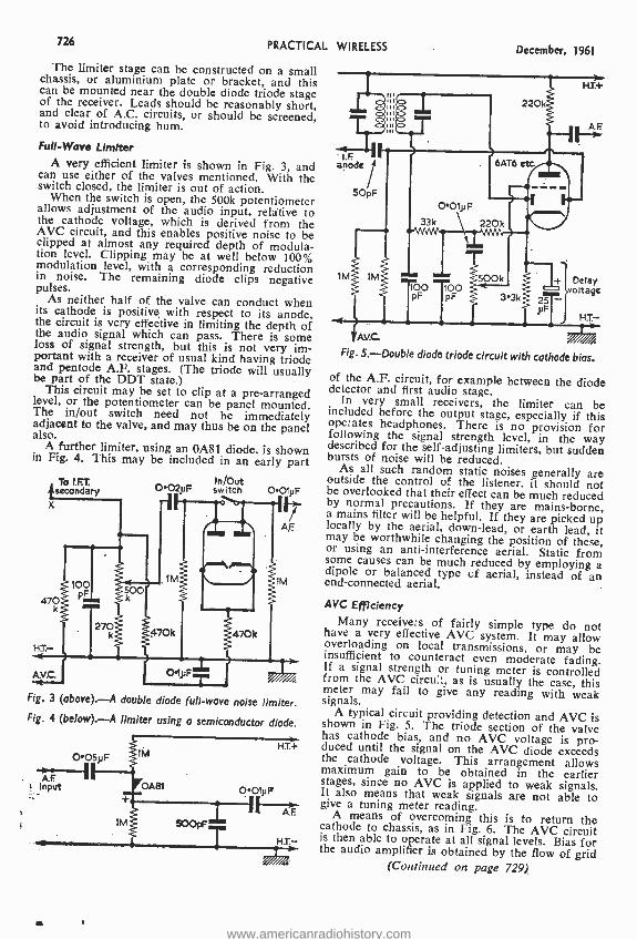
726 PRACTICAL WIRELESS December, 1961
The limiter stage can be constructed on a small chassis, or aluminium plate or bracket, and this can be mounted near the double diode triode stage of the receiver. Leads should be reasonably short, and clear of A.C. circuits, or should be screened, to avoid introducing hum.
Full -Wave Limiter A very efficient limiter is shown in Fig. 3 and
can use either of the valves mentioned. With the switch closed, the limiter is out of action. When the switch is open, the 500k potentiometer
allows adjustment of the audio input, relative to the cathode voltage, which is derived from the AVC circuit, and this enables positive noise to be clipped at almost any required depth of modula- tion level. Clipping may be at well below 100% modulation level, with a corresponding reduction in noise. The remaining diode clips negative pulses.
As neither half of the valve can conduct when its cathode is positive with respect to its anode, the circuit is very effective in limiting the depth of the audio signal which can pass. There is some loss of signal strength, but this is not very im- portant with a receiver of usual kind having triode and pentode A.F. stages. (The triode will usually be part of the DDT state.)
This circuit may be set to clip at a pre- arranged level, or the potentiometer can be panel mounted. The in /out switch need not be immediately adjacent to the valve, and may thus be on the panel also.
A further limiter, using an 0A81 diode, is shown in Fig. 4. This may be included in an early part
To t.F.T. isecondary X
470
HT.- <
A.V.C.
OO2pF swit0ch 001pF
AF
11M
O1pF
470k
} . >
Fig. 3 (above). -A double diode full -wave noise limiter. Fig. 4 (below). -A limiter using a semiconductor diode.
FOAM
y.OO5p F
A.F Input
H.T.+
001pF I q,F
1Mg 900pF
HT-
anode
SOpF
IM 1M
Ave. Fig. 5.- Double diode triode circuit with cathode bias.
of the A.F. circuit, for example between the diode detector and first audio stage. In very small receivers, the limiter can be included before the output stage, especially if this operates headphones. There is no provision for following the signal strength level, in the way described for the self- adjusting limiters, but sudden bursts of noise will be reduced. As all such random static noises generally are outside the control of the listener, it should not be overlooked that their effect can be much reduced by normal precautions. If they are mains -borne, a mains filter will be helpful. If they are picked up locally by the aerial, down -lead, or earth lead, it may be worthwhile changing the position of these, or using an anti -interference aerial. Static from some causes can be much reduced by employing a dipole or balanced type of aerial, instead of an end -connected aerial.
AVC Efficiency Many receivers of fairly simple type do not have a very effective AVC system. It may allow overloading on local transmissions, or may be insufficient to counteract even moderate fading. If a signal strength or tuning meter is controlled from the AVC circus:, as is usually the case, this meter may fail to give any reading with weak signals. A typical circuit providing detection and AVC is shown in Fig. 5. The triode section of the valve has cathode bias, and no AVC voltage is pro- duced until the signal on the AVC diode exceeds the cathode voltage. This arrangement allows maximum gain to be obtained in the earlier stages, since no AVC is applied to weak signals. It also means that weak signals are not able to give a tuning meter reading. A means of overcoming this is to return the cathode to chassis, as in Fig. 6. The AVC circuit is then able to operate at all signal levels. Bias for the audio amplifier is obtained by the flow of grid
(Continued on page 729)
220k.`>
,"<;
6AT6 etc
0O1 p F
33k 220k
_. ...., 00
FF 0 fF 3 3k
500
25 pF
H T.+
+ Delay voltage
H.T.-
www.americanradiohistory.com

December, 1961 PRACTICAL WIRELESS 127
TEST METERS FOR EVERY PURPOSE & POCKET
1,000 O.P.V. Model U.1. Reads A.C. & D.C. Volts up to 1,000; D.C. Current to 500 mA: Resis- tance to 2005. Basic movement 3001.1A. Easily read open scale. Size 5}1n. z 31in. z 2110.
88.19.8
2,000 O.P.V. Model TP -1O. Reads A.C. & D.C. Volts up to 1,000; D.C. Current to 500mA; Resistance to 1 Meg; Capaci- tance to lµF; Decibels from -20 to +36; Output jack for Audio Measurements. Size 3}1n. z 5 z
23.19.6
20,000 O.P.V. Model TP-5S. Reads voltages up to 1,000 D.C. at 20,000 Ohms per volt and A.C. at 10.000 o.p.v.; D.C. Current to 500mA: Resistance to 10 Megs; Capacitance to 0.111F: Decibels from -20 to +36. Size 3lin. z 55ín. z 111n.
25.19.6
30,000 O.P.V. Model 500. Volts 1.000 at 2 C . Á C.a 20.000 1Amps D
Current; 60 Megs Resistance: -20 to +58 Dbs; Internal buzzer short circuit warning. Size 3 5/161n. z1625//leln. z 24in.
All Brand New stock, with test leads, prode, and internal batteries. Fully guaranteed. S.A.E. further details.
UNIVERSAL AVO METERS. In first -class condition. thoroughly overhauled and guaranteed perfect. In the well- known AVO styling with 51n. hand calibrated Mirror Scale. Complete with leads and internal batteries. The 50 RANGE MODEL
HMS PER VOLT MODEL 8, and
NLY 217.10.0. .((Regd P.. &OP 5/- on either). S.A.E. for full details. CRYSTAL CALIBRATOR No. 10. A superb Crystal Controlled Wavemeter lust released by the Ministry of Supply. Has directly calibrated dial for nominal coverage of 1.5 -10.0 Mc /s. but may actually be used from 500
KC/s. type 1T4,
to or51R5 and
Complete with CV286 (Neon Stabiliser),
valves
Book. Size Tin. x 7;in. x 4ín., weight 5 lbs. Used but in first class condition. ONLY 22.19.6. Carr. 3/6. B.C. 221 FREQUENCY METERS. The famous American crystal controlled, portable frequency measuring standard. Coverage r
original numbered tn book. Perfect a de. Illustrated details onrequest. ONLY £16.
PCR COMMUNICATIONS RECEIVERS Manufactured by Pye & Philips. One of the Army's most versa- tile and sensltivelsets. RF stage and 2 of I.F., using 6 British I.O.
Flywheel Tuning ewiitth locking device. Aerial Calibrated Dial,
n
and Vol. Controls. Band Switch front panel jacks for speaker or
emetal case, ï s al50-Ótrs PCR phones. In
/c me nd 82,00 metres. has internal 5in. speaker. REME reconditioned AS NEW £9.19.6, OR used very good condition. 27.19.6. Model PCR I has similar L & M waveband coverage. Short wave 6- 22540/s, but no speaker. Used good cond. sets only avail.26.19.6 Every receiver aerial tested before deep. Add 10 /6 carr. all models. Designed to operate from bulky EXTERNAL power supply, but
AL PACK fitted with BRAND
v A.C. a an extra cost of £2. INTER-
N
6 TRANSISTOR PERSONAL RECEIVER Designed by the techni- cal staff of Practical Wireless; easy to build. using printed circuit and 1st Grade Matched Transistors and Diode. Full Medium and Long Wave coverage to inter - I Com is only) e-
re-
nal speakers. All parts sold senately (new
request Constructional details COST ß1/6
TERY AND CABINET 28.19.6.
"THE GOOD COMPANION" THE FINEST COMBINED PORTABLE & CAR RADIO YET DESIGNED
FOR THE HOME CONSTRUCTOR
* 750 mW output. * 6 transistors and 2 diodes. * Full Medium and Long Wave coverage. * Quality speaker. * Pre -aligned I.F.T.'s. * Brilliantly styled 2 tone cabinet, size 11 z 8 z 31ns. * Very fine tuning with calibrated dial. * Latest printed circuit. * Internal high gain aerial, with car aerial socket. * Easy to follow construction data (available separately 3/6.)
All parts sold separately and full illustrated details will be sent on request. i g 19 6 plus 5/-
post and fas. Total cost ß/ O (Battery 3/6 extra.)
"POCKET 4" TRANSISTOR RECEIVER Attractive cabinet as illustrated for P.W. 6 ". Uses miniature speaker, proper tuning condenser, and volume control. Built -in aerial makes unit efficient and portable. Ideal for the beginner. Full medium wave coverage. All components bó k free wit42/6 arts or separately 1eS A.E. for parts price list.
HARRIS ELECTRONICS 138 Gray's Inn eRooad, London, W.C. I TERminus 79)
(LONDON) LTD popp Please include carriage costs on All items
(Open iLane Station wand 5Wmina bymbus from King's
Holborn
www.americanradiohistory.com

728 PRACTICAL WIRELESS
SOLDERING IRON
1819 30 -watt 230 -volts A.C. Portable, for lightweight applications. High stable heat characteristics assure long life and safety in use. Features a removable handle that may be used to cover the tip and barrel to permit the iron to be carried safely even while hot. Complete with vinyl bag, mains lead and plug. Spares available. Element, 4'6; Bit, 1,6. Size: overall length 10}ín. (6 }in. when not in use). Carriage free.
DE -LUXE TAPE CABINET Exclusive de- sign. Two -tone rexine. Detachable lid. Can be adapted to R /Player cabinet.
Carr. 51
Size approx. 12k x 91 x 7 ins. Colour Red or Brown. Ins. and
-.
15/-E
14"
TUBES MULLARD, Etc.
15 "& 12" X- RENTAL
SERVICE STOCK
Cantase 5'-
EX- RENTAL REPLACEMENT STOCK
Carriage 5'6
9d. SALVAGE VALVES GUARANTEED C2C EB9I
DI66 EF50
D152 SP6I EASO D77
l'9d, PEN46 N309 Z77 N339 6FI KT33C B36 KT63 DH77 LN152 EB41 LN309 6P25 LZ319 N 152 EL32 Post 1-9d. 6-2'.
ECC3I ECC34 VR35 VR5I -
KT W6I U22 U31 U3S UF42 UB41 UBF80 W76
12-3'-.
VR106 VR107 EF91
V R201
2'9d. PL33 U151 U281 UL46 ECC8I ECC82 EF42 EF80 EF92
4DI 6D1 6F12
6F13
5'9d. EBC33 EBF80 ECLBO EL33 EL38 EL4I U152 U251 PCC84
6D2 15D2
6F14 6F15
PCF80 PCF82 PL38 PL8I PL82 PL83 PY80 PY81 PY82 PZ30
TV CHASSIS 5P6 Plessey, less valve and tube. Circuit Inc Ins. and Carr. 7'6. Salvage. Badly Stored.
*- *- *- *- *- * -* -* -* MAIL ORDER ONLY
215 ILFORD LANE, ILFORD, ESSEX
Stomp for FREE Catalogue
Phone: ILF-6003
December, 1961
SOUND REPRODUCERS (LONDON) LTD. The Transistor Component Specialists Dept. P.W. 15, 7 Jepson Road, Forest Gate,
London E7, (Mail Order Only)
NOTE THESE FEATURES- * Three top quality Transistors by famous makers (n rejects). * Moving Coil Speaker. * Fully Tunable ove Medium Waves. * Ferrite Rod Aerial. * Solenoid Woun Coils. * On /Off Switch. * Separate Volume and Reactio Controls. Drilled and Punched Chassis. * Double Diod Detector. * Plug in 9 v. Battery. * Full Easy to Follo Instructions. * Point to point wiring diagram. * No Radi knowledge required. This set is fully portable and require no aerial or earth. All components tested before dispatc and guaranteed 12 months. * Complete Satisfaction o money refunded. All components supplied separately Instruction Book 1'6 post free.
SPECIAL INTRODUCTORYtOFFER. All mponenta
Parts and Blue Plastic Case, as illustrated. Post and Packing 316. Personal Ear Phone with instructions, 91. Post and Packing Free. Battery Extra, PP3, 2'6.
SNIPS XA101, 61 -; SB078, B1 -; SB305, 9' -; XB102, 9' -; G.E.C. S.1, 6'6 Miniature Resistors, 4}d.; Electrolytic!, 200, 100, 50, 32, 8 4, 2, mfd., 1'9. Ferrite Rod, 6in. long, } or }in., l'9. Litz Wire 3d. yd. We can supply all components for the P.W. Tutor. Send for list. Orders on above, value LI to £3, 10% reduction, over L3, 15%. Please add 6d. P. & P. up to LI; 1'- LI to L3 1'6 over £3. OSMOR, REPANCO, ARDENTE STOCKISTS
3d. Stamp for Catalogue.
INTRODUCING .. .
THE TRAVELLER A highly sensitive Transistor Receiver using 3 top quality Transistors and 2 Diodes in latest circuitry.
o
d
e
o w
h
£3.17.6
THE
SUPERHETERODYNE RECEIVER
By A.T. Witts, A.M.I.E.E. Seventh Edition
This book describes the operation of Superheterodyne Receivers in the clearest possible manner. It makes every detail of the subject understandable and provides the essential working knowledge required by every student of radio and service engineering. The superheterodyne receiver is, of course, still the basic circuit for the majority of domestic (including television) and communication receivers. In this new edition the book has been thoroughly revised, bringing in completely new chapters on frequency -modulation receivers, tran- sistor superheterodynes and communication -type receivers. 20/- net.
PITMAN 7
www.americanradiohistory.com

December, 1961 PRACTICAL WIRELESS
(Continued from page 726) current through the high value resistor, which should be 5.6M to 10M.
With this type of circuit, tuning meter indica- ations will become possible at very low signal levels. A very similar effect, for comparative pur- poses, may be obtained by shorting the cathode bias resistor in Fig. 5, though the A.F. amplifier will then be less effective.
The increase in AVC action will bring about a
general reduction in volume; since a larger AVC voltage is being obtained, this is unavoidable. With
33k O01}iF
100 pF
HT
Fig. 6. -A modified form of bias.
very small receivers, the increase in AVC efficiency can still be worthwhile, if sufficient volume is
obtained.
Controlled Stages R.F. and I.F. stages frequently receive the screen
grid supply through a single resistor, as in Fig. 7.
This is a convenient and economical method, but does not allow best operation of the AVC circuit.
When AVC is applied, the cathode current falls, and there is a drop in current through the 33k resistor. This reduced current also reduces the voltage drop in the resistor, so that the screen grid voltage rises. In many cases this rise is con- siderable, and, to some extent, it off -sets the reduc- tion in gain caused by the AVC circuit.
If the screen is fed from a potential divider, as in Fig. 8, this effect is greatly reduced. Resistors R1 and R2 are so chosen as to maintain the voltage
H.T.t
AVC.
Fig. 7.-An l.F. stage with a dropper for the screen grid.
Fig. 8. -A modification to the circuit of Fig. 7 to increase
the effects of the AVC.
729
at about the usual figure. R1
The lower the value of these resistors, the more stable will the screen grid voltage become. Unfor- tunately, very low values are impossible because the bleeder current taken from the H.T. supply would be excessive. Even quite hig values will, however, help to avoid so much fluctuation in voltage. A total value of about 50k will require an HT- additional H.T. current of 5mA, with a 250V supply.
Calculation The current through R2 can be found by divid-
ing the required screen grid voltage by the resis- tance value; for example, it would be about 3mA with 150V on the grid and 47k for R2. The cur- rent through R1 is the total of the screen grid current, and the current through R2. That is, 5mA, in this example, if the screen grid takes 2mA. The value of R1 is therefore such as to cause the required voltage drop at this current. If the H.T. line is 250V, then 100V must be dropped. So from V/I the value of R1 is 20k or 22k (the nearest preferred value). The bleeder current is V /(R1+R2), or 250/69k, or under 4mA.
FAULTS IN VHFIF.M. RECEIVERS (Continued from page 722)
also be caused by the normal operating tempera- ture in the set after several years' continuous use.
These troubles eventually result in a break in one of the printed wires. Unfortunately, the break may not be readily visible without the use of a magnifying glass and may also be of an inter- mittent nature. In a grid circuit or in the detector, a wiring break may not cause total failure, but could result in curious hum effects which might not show up until the temperature inside the set rose and the disconnection occurred owing to flexing of the printed board.
Such faults can be difficult to locate, but the trouble can often be located by gently flexing the printed board, applying piessure to various sections until the fault condition can either be brought on, or corrected. One must be very careful, however, to ensure that a break is not unwittingly caused by rough handling during this process. When the fracture has been located, it may be repaired either by thoroughly cleaning the surface of the conductor and applying a blob of solder across the break, using the minimum amount of heat for the shortest possible time, or by replacing the whole length of the conductor with a wire between its two ends.
(To be continued)
www.americanradiohistory.com
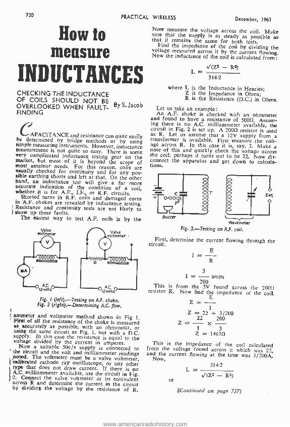
730 PRACTICAL WIRELESS December, 1961
How to measure
INDUCTANCES CHECKING THE INDUCTANCE OF COILS SHOULD NOT BE OVERLOOKED WHEN FAULT- By S. Jacob FINDING
CAPACITANCE and resistance can quite easily be determined by bridge methods or by using simple measuring instruments. However, inductance measurement is not quite so easy. There is some very complicated inductance testing gear on the market, but most of it is beyond the scope of most amateur needs. For this reason, coils are usually checked for continuity and for any pos- sible earthing shorts and left at that. On the other hand, an inductance test will give a far more accurate indication of the condition of a coil, whether it is for A.F., I.F., or R.F. circuits. Shorted turns in R.F. coils and damaged cores
in A.F. chokes are revealed by inductance testing. Resistance and continuity tests are not likely to show up these faults.
The easiest way to test A.F. coils is by the
Valve voltmeter
Fig. I (left).- Testing an A.F. choke. Fig. 2 (right). Determining A.G. flow.
ammeter and voltmeter method shown in Fig 1. First of all the resistance of the choke is measured as accurately as possible, with an ohmmeter, or using the same circuit as Fig. 1, but with a D.C. supply. In this case the resistance is equal to the voltage divided by the current in amperes.
Now a suitable 50c /s supply is connected to the circuit and the volt and milliammeter readings noted. The voltmeter must be a valve voltmeter, calibrated cathode ray oscilloscope, or any other type that does not draw current. If there is no A.C. milliammeter available, use the circuit in Fig. 2. Connect the valve voltmeter or its equivalent across R and determine the current in the circuit by dividing the voltage by the resistance of R.
Now measure the voltage across the coil. Make sure that the supply is as steady as possible so that it remains the same for both tests. Find the impedance of the coil by dividing the voltage measured across it by the current flowing. Now the inductance of the coil is calculated from:
(Z2 - R2) L
314.2
where L is the Inductance in Henries; Z is the Impedance in Ohms; R is the Resistance (D.C.) in Ohms.
Let us take an example: An A.F. choke is checked with an ohmmeter
and found to have a resistance of 50052. Assum- ing there is no A.C. milliammeter available, the circuit in Fig. 2 is set up. A 20011 resistor is used as R. Let us assume that a 12V supply from a transformer is available. First measure the volt- age across R. In this case it is, say, 3. Make a note of this and quickly check the voltage across the coil; perhaps it turns out to be 22. Now dis- connect the apparatus and get down to calcula- tions.
Buzzer
Bet
Wavemeter Fig. 3.- Testing an R.F. coil.
First, determine the current flowing through the circuit.
I = E
R
3 I = - amps
200 This is from the 3V found across the 20011 resistor R. Now find the impedance of the coil
E Z = -
I Z = 22 _ 3/200
22 200 Z = - - -
1 3 Z = 146711
This is the impedance of the coil calculated from the voltage found across it which was 22, and the current flowing at the time was 3/200A. Now,
or
314.2 L -
(Z2 - R2)
(Continued on page 737)
www.americanradiohistory.com
December, 1961 PRACTICAL WIRELESS 731
BOOST MODIFICATIONS
FOR
"PW" POCKET SU PERH ET SIMPLE A -Z MODIFICATION TO BOOST
AND IMPROVE THIS SET
The Pocket Superhet is a high quality miniature receiver for operation on Medium and Long Waves. Dimensions are only 51 x 32 x tin. The
circuit uses 6 transistors and incorporates modern miniature compo- nents of the best quality which combine to give superb performance normally associated with much larger sets. The printed board con-
struction ensures success to every enthusiast able to follow the simple Step by Step instructions.
NEW CONTEMPORARY CASE
Jllillllllllllll1111111111111111111111111E1111111111111111I111111L SIMPI- -
= A-Z = ç STEP-BY-STEP = =
CTIONA g00KlEi =
= CONSTRU116
EACH = G
g
-
e MODIFICATIONS IF
CAT O
_ WIRING
pIR AMS ss
"BLOWN-UP" pGM =
_ THEORETICAL CIRCUIT
_ _
PHOTOGRAPHS _
' 11111 111U111111111111111111111111111p11
11 0
The new contemporary case has been
designed to take the early models of
this receiver as well as the modified
circuit. We feel sure you will find this
new case one of the most attractive you
have ever seen.
FREE INFORMATION
from your Dealer or Direct.
osmor 418 BRIGHTON ROAD, S. CROYDON. CRO 5148/9
www.americanradiohistory.com
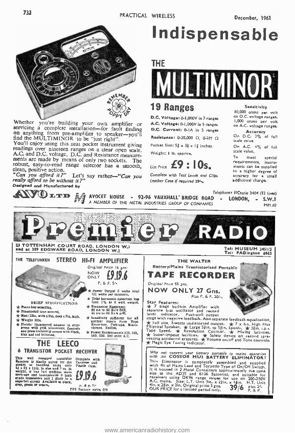
732 PRACTICAL WIRELESS December, 1961
APYG Whether you're building your own amplifier or servicing a complete installation -for fault finding on anything from pre -amplifier to speaker -you'll find the MULTIMINOR to be "just right ". You'll enjoy using this neat pocket instrument giving readings over nineteen ranges on a clear open scale. A.C. and D.C. voltage, D.C. and Resistance measure- ments are made by means of only two sockets. The robust, easy -to -read range selector has a smooth, clean, positive action. "Cart you afford it Let's say rather -"Can you really afford to be without it ?" Designed and Manufactured by
Indispensable THE
MULTIMINOR 19 Ranges D.C. Voltage: 0- 1,000V in 7 ranges A.C. Voltage: 0- 1,000V in 5 ranges D.C. Current: 0-IA in 5 ranges
Resistance: 0- 20,000 0, 0-2M f2
Pocket Size: 51 x 3; x I -d' inches.
Weight: I lb. approx.
List Price 10x Complete with Test Leads and Clips Leather Case if required 39f.,
Sensitivity 10,000 ohms per volt on D.C. voltage ranges. 1,000 ohms per volt
on A.C. voltage ranges.
Accuracy On D.C. 3% of full scale value.
On A.C. 4% of full scale value.
To meet special requirements, instru- ments can be supplied to a higher degree of accuracy for a small additional charge.
Telephones VECtoria 3404 (12 lines) AVOCET HOUSE . 92 -96 VAUXHALL- BRIDGE ROAD . LONDON, - S.W.I A MEMBER OF THE METAL INDUSTRIES GROUP OF COMPANIES MM.tO
23 TOTTENHAM COURT ROAD, LONDON W.1 and at 309 EDGWARE ROAD, LONDON W.2
THE TELEFUNKEN STEREO HI -FI AMPLIFIER Original Price 16 ens.
BRIEF SPEOLF /CATIONS: * Piano key selecting, * Preseleeted tone austral, * Siae: l2in, wide z Bin. deeps Sin. high. * Weighs Sibs. * Finish: Hammered enamel in grey, green with gold trimmings. Controls and press buttons in cream with black, blue and red lettering.
NOW ONLY 9.19.6
P. & P. 51-
* Power Output 5 watts total (2f watts per channel,. * Total harmonic distortion leu than 1% at 1 watt output. * Frequency Response: 30 cis to 90 Rols 2dB. 45 ale to 30 Eels tdB. * Sensitivity sufficient for all normal inputs from Tape Recorders, Pick -ups, Micro- phones. Radios.
* Power Requirements 110, 125, 150, 220. 240 volts A.C.
THE LEECO 6 TRANSISTOR POCKET RECEIVER
This well designed transistor Receiver is ideally suited for the poeket or handbag bong only 4i z 21 z Itin. in size and 7 oz. in weight, il has lull medinm wave .overage and incorporate. It high grade transistors and 1 diode in a mperhet eternit Available in black, (rep, green or cream.
Complete with Earpiece and Plastic Cade.
9.19.6 k p.?i-
FM Batters extra 2/0
Tel: MUSEUM 3451/2 Tel: PADington 6963
THE WALTER Battery /Mains Transistorised Portable
TAPE RECORDER Original Price 55 gns.
NOW ONLY 27 Gns. Plus P. & P. 201,
Star Features: * 7 stage built -in Amplifier with separate bias oscillator and record level indicator. Push -pull output stage with negative feedback. Also separate feedback equalisation * Full size, 3 -watts undistorted output- * 7 x 4in. High Flux Elliptical Speaker. * Large 51in. sp S }in. Spools. * 32in. i. p.s Tape Speed. * Revolution Counter. * Mixing facilities * Super- impose facilities. * Safety device on record (pre venting accidental erasure). * Volume on /off and Tone controls. * Magic Eye Tuning Indicator.
Why not convert your battery portable to mains operation with the COSSOR MU2 BATTERY ELIMINATOR? This Eliminator is completely assembled and supplied with Oft of Mains Lead and Torpedo Type of On/Off Switch. It is housed in 2 Metal Containers approximately the same size as the AD35 and B126 Batteries, and suitable for receivers using DK96 range values for use on 200 -250V A.C. mains. Size: L.T. Unit Sin. x 2 1in. x I/iin. H.T. Unit 4in. x 2/ e. x 2M. Original price 3 gns. 39 /L plus 2t- OUR PRICE for a limited period only. 7 V P. & P.
www.americanradiohistory.com
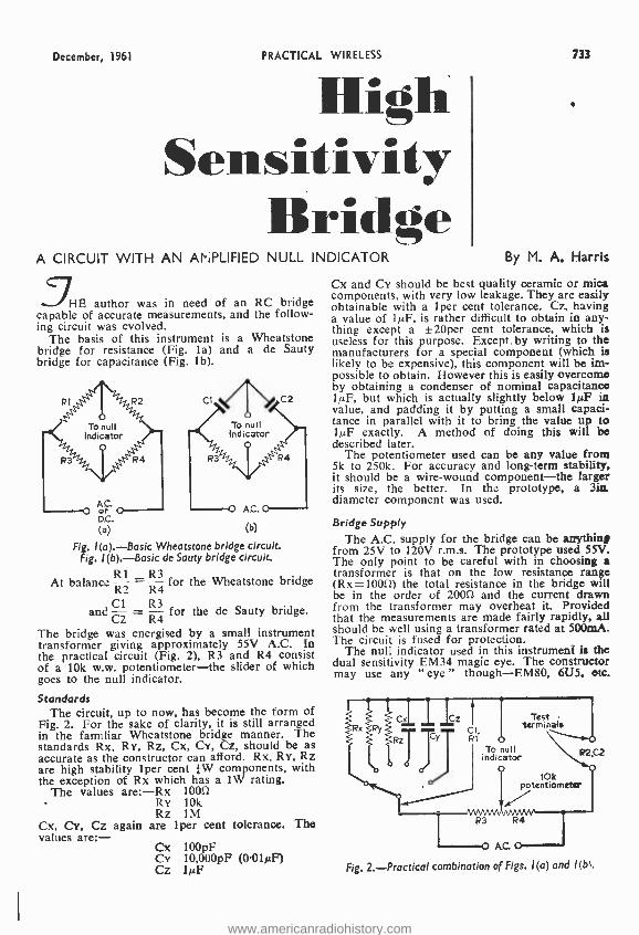
December, 1961 PRACTICAL WIRELESS 733
flih Sensitivity
lin d4e A CIRCUIT WITH AN AriPLIFIED NULL INDICATOR By M. A. Harris
3HE author was in need of an RC bridge capable of accurate measurements, and the follow- ing circuit was evolved.
The basis of this instrument is a Wheatstone bridge for resistance (Fig. la) and a de Sauty bridge for capacitance (Fig. lb).
To null indicator
Fig. 1(a). -Basic Wheatstone bridge circuit. Fig. 1(b). -Basic de Sauty bridge circuit.
At balance R2 R4
for the Wheatstone bridge
Cl R3 and
C2 R4 for the de Sauty bridge.
The bridge was energised by a small instrument transformer giving approximately 55V A.C. In the practical circuit (Fig. 2), R3 and R4 consist of a 10k w.w. potentiometer -the slider of which goes to the null indicator.
Standards The circuit, up to now, has become the form of
Fig. 2. For the sake of clarity, it is still arranged in the familiar Wheatstone bridge manner. The standards Rx, RY, Rz, Cx, CY, Cz, should be as accurate as the constructor can afford. Rx, RY, Rz are high stability 1per cent -}W components, with the exception of Rx which has a 1W rating.
The values are: -Rx 1000 RY 10k Rz 1M
Cx, CY, Cz again are 1per cent tolerance. The values are:-
Cx 100pF Cy 10,000pF (001µF) Cz lµF
Cx and CY should be best quality ceramic or mica components, with very low leakage. They are easily obtainable with a 1per cent tolerance. Cz, having a value of IMF, is rather difficult to obtain in any- thing except a ±20per cent tolerance, which is useless for this purpose. Except by writing to the manufacturers for a special component (which is likely to be expensive), this component will be im- possible to obtain. However this is easily overcome by obtaining a condenser of nominal capacitance lkiF, but which is actually slightly below 10F in value, and padding it by putting a small capaci- tance in parallel with it to bring the value up to 1µP exactly. A method of doing this will be described later.
The potentiometer used can be any value from 5k to 250k. For accuracy and long -term stability, it should be a wire -wound component -the larger its size, the better. In the prototype, a 3in diameter component was used.
Bridge Supply
The A.C. supply for the bridge can be anytbin/ from 25V to 120V r.m.s. The prototype used 55V. The only point to be careful with in choosing a transformer is that on the low resistance range (Rx =1000) the total resistance in the bridge will be in the order of 2000 and the current drawn from the transformer may overheat it. Provided that the measurements are made fairly rapidly, all should be well using a transformer rated at 500mA. The circuit is fused for protection.
The null indicator used in this instrument. is the dual sensitivity EM34 magic eye. The constructor may use any "eye" though -EM80, 6U5, etc.
Test termnale
To null indicator
o 10k
potentiometer
Fig. 2. Practical combination of Figs. 1(a) and 1(b1.
www.americanradiohistory.com

734
From Bridge
II
D 52
100k
VI ECC83
o Sta
PRACTICAL WIRELESS December, 1961
and a valve rectifier. A switch was incorporated into the prototype to
enable the magic eye and amplifier to be used to detect a null other than that from the bridge. The connection was brought out on to the front panel as a coaxial socket.
Screened lead is used where shown because the bridge uses 50c /s and hum could be picked up in 3 6 s the wiring and this would not enable the magic eye to indicate a sharp, definite null.
Power Supplies
hLT.t
; 51c o I
1M
r al
Neil Input
2.2k O1 pF
NIB am.
v2 :EM34
1M
IM IM
2 7
xx
Fig. 3. -The amps tied null indicator. - although the EM34 is the most sensitive. An amplifier is used in conjunction with the magic eye to provide the instrument with greater sensitivity. The amplifier (Fig. 3) is switched out to obtain an approximate balance point, and then switched in to obtain greater accuracy. This facility is pro- vided so that rapid readings are easily obtained. If the amplifier were left permanently connected, the eye would be rather slow to open, especially on the capacitance ranges.
D.C. Restoration From the amplifier, the signal is D.C.-restored
so that only a negative voltage goes to the grid of the magic eye. In the prototype a double triode - an ECC83 -was used simply because it was to hand (Fig. 3). One triode was used as the voltage amplifier and the other half strapped as a diode to D.C. - restore the signal. If the constructor wishes, he may use any double triode or a single triode
i
Almost any sort of power supply can be used with this bridge, provided it gives IOmA at 250V and 0.5A at 6.3V. The instrument can be powered from another instrument that has enough power to spare. The prototype used a 250V half -wave winding and a 6.3V winding on a small replace- ment type of transformer. The rectifier used is an EZ80, so that a separate heater winding is not required. A full -wave winding could be used if the constructor wishes. Since the EZ80 has two anodes (in the prototype these were strapped together), it would serve quite well as a full -wave rectifier. Almost any rectifier could be used, however (a 6H6 or EB34 has been tried and found successful). A metal rectifier would also be suitable, since the rating need only be IOmA or so. An H.T. fuse was fitted.
The on /off switch is of the double -pole variety, thus isolating the equipment completely from the mains. A panel light is fitted- either the neon type wired (via a limiter resistor) across the bridge side of the switch, or an ordinary 6.3V bulb wired across the heater supply.
The circuit of the power supply is straightfor- ward. The supply terminals were brought out to a three -pin miniature mains socket screwed on to the front panel. If the constructor does not wish to go to the expense of buying one of these, the mains lead can go through a hole in the back panel.
For the sake of clarity, the complete circuit diagram is given in Fig. 4, together with a list of parts (page 737). It is advisable to use screened
(Continued on page 737)
G T H O Si A
L.F. CHOKE
IC
A H TAP Vi ECC83 V2 EM34 V3 EZBO
(B9A) (INT.. OCTAL) (B9A)
R3
H If. IC 10
Á IG
Cx=tOOPP Cyg.O.OIyF
00000 1- C2 i C1 t'16yF
1YF " T
- -T eF3 6
X X T2
VIA ECCB3
53 CimtyiF V3
EZ80
X[ E3V
HEATER xr
TEST IMINALS
ALL SCREEN NG OF LEADS CONNECTED TO CHASSIS
Fig. 4. -The complete circuit diagram of the bridge unit.
www.americanradiohistory.com

December, 1961 PRACTICAL WIRELESS
"6 plus I" TRANSISTOR RADIO KIT BEST EVER VALUE!
MANUFACTURERS' SURPLUS BARGAIN OFFER. Further kit supplies now available. Original purchase of this popular kit were rapidly sold out. This kit is a modern sensitive quality circuit Receiver Unit with all the latest features. Six BVA transistors and 1 diode, printed circuit. Med. and Long waves. Ferrite aerial, oar radio coupling coil 500mW push -pull output into 3 ohm speaker, attractive gilt dial and slow -motion tuning, etc. Size approx. 8 x 21ín, Cabt. size 9 x 5f x 311n.
KIT of Parts dc ud -S BARGAIN OFFER
Set of 6 Transistors and COMPiete Kit $6.19.6 1 Diode 45/-. P. & P. 2/8. less Speaker. Carr. 2/6
3 ohm Speaker 7 x 311n.-ONLY 15/6. P. & P. 1/6. Send 3d. stamp for full details. Circuit and Instructions L& Cabinets 25 /- extra.
New VALVES Boxed
155 7/8 185 7/8 384 7/8 3v4 7/9 DAP98 9/- DP88 9/- DE98 9/- DL96 9/- EOC81 8/- 110082 8/-
ECC83 8/- ECL82 9/8 ECL80 10/8 EF80 8/- EF86 12/8 EL84 8/8 HIM 9/8 EY88 10/- EZ81 7/6 GZ32 12/8 EM81 9/8
Ail Guaranteed
PW84 9/6 PCF80 9/6 PCL83 12/6 PCL84 12/6 PL81 12/8 PL82 9/8 PL83 10/8 PY82 12/8 PY81 9/6 PY89 7/8 II25 12/6
Electrolytic' AN Types New Stook CAN TYPES
8+8/450V 4/6 8 +16/450V 8/- 32 +32/275V 4/6 55 +50í350V 8/8 80 +250/
275V 12/6 100+200/
275V 12/6
TUBULAR 25/25V 1/9 50112V 1/9 58150V 2/- 100/25V II- 0/450V 2/8 18/450V 8/8 16+18/450V 5/8 32+32/450V 8/8
Ersin Multicore Solder 60/40 3d. per yard. ilb. 2/6, etc.
RECORDING TAPE - SPECIAL BARGAIN OFFER Famous American Columbia (CBS) Premier Quality Tape at NEW REDUCED PRICES. A genuine recommended Quality Tape -TRY ITI Brand new. boxed and fully guaranteed. Fitted with leader and stop foils.
Standard Long Play Double Play 51n. BCOSt. 15/- 900ft. 18 /6 1.200ft. 31/6 Min. 901)1t. 16/6 1,200ft. 22/6 1,800f t. 39/6 71n. 1.200ft. 21/- 1.800ít. 82/6 2,400ft. 47/6
Post and Packing, per reel, 11 -, plus Bd. each for additional reels. SPECIAL OFFER -3in. mfrs. surplus tape, 225ft. 5/6. P. & P. per reel Bd. Plastic Tape Reels. Sin. 2/6, Sin. 3/ -; Min. 3/3. 7ín. 3/6.
Volume Controls --5K -2 Meg - ohms. 3ín. Spindles Morgan- Me Midget Type. 11ín. diam. Guar. 1 year. LOG or LIN ratios less Sw. 3/ -. DP. SW. 4/6. Twin Stereo less Sw. 6/6. D.P. Sw. 8/ -.
COAX 80 OHM CABLE High grade low loss Cellular air spaced Polythene -Tin. diameter. Stranded cond. Famous mfrs. Now only 8.1. per yard. Bargain Prices - Special lengths -
20 yds. 9/ -. P. & P. 1/6. 40 yds. 17/6. P. & P. 2/-. 80 yds. 25/ -. P. & P. 3/ ,
Coax Plugs 1/ -. Sockets li -. Couplers 1/3. Outlet Boxes 4/6
TAPE RECORDER KIT Special Oiler. Latest 5 valve circuit based on Mullard's design. Magic eye and tone controls. Printed circuit al- ready wired. A sensitive quality recorder B.S.R. Amp Kit 95/ , B.S.R. Tape Deck 28.10.0. Collaro Amp. Kit 26.5.0. Collaro Tape Deck 212.10.0. Set of 5 valves 45/ -. Special Unit Kit Prices - Send stamp for detailed list. Construction and circuit de- tails 2/8. Bargain Complete B.S.B. Kit 21840.0. Carr. 4/6.
Condensers-Silver Mica. All values. 2pF to 1,000pF, 8d. each. Ditto, Ceramics 9d. Tub. 450V T.C.C., etc., 0.001 mfd., 0.01 and 0.1/350V, 9d. 0.02 - 0,1/500V L -. 0.25 Runts 1/6. 0.5 T.C.C. 1/9, etc.. etc. Close Toi, S /Micas -10 % 6pF -500pF Bd. 8011- 5,000pF 1/-. 1% 2pF- 100pF 9d. 100pF-500pF lid. 575pF-5,0000F L8. Resistors - Full Range 10 ohms -10 meg- ohms 20% 1 and OW 3d., 1W 5d. (Midget 1W 90.
modern 1 t bí10%
1W 50.. 1W 7d. 5% 6W 9d., 1% 1W U8. W/W Resistors 25 ohms to 10ÌS. 5W 1/3, 10W 1/6, 15W 2/ -. Preset T/V Pots. W/W 25 ohms -50 K 3/ -. 50K -2 Meg. (Carbon) 3/ -. JASON FM TUNER UNITS Designer -approved kits of parts:
FMTI. 5 gas. 4 valves, 20/-. FM1'2, £7. 5 valves, 37/6. JTV MERCURY 10 gnu. JTV2 213.19.6. 4 valves, 32/6.
NEW JASON FM HAND- BOOK, 2/6. 48 hr. Alignment Service 7/6. P. & P. 2/6.
Speakers P.M. -3 ohms 251n. Elac 17/6. 31in. Goodman 18/6. Sin. Rola 17/6. 61e. Else 18/6. '1 x 41n. Goodmans 18/8. 81n. Rola 20/ , 101n. R. x A. 25/ -. 10 z bin. Goodmans 25/ , E.M.I. Tweeter 23/6.
Speaker Fret - Expanded bronze anodised metal 8 x Stn. 2/3, 12 x 81n. 3/ -, 12 x 121n. 4/6. 12 x 16ín. 8/ -, 24 x 121n. 9 / -, 36 x 12ín. 13/8, etc. etc.
TYGAN FRET (contemn. pat.) 12 a 12ín. 2/ -. 12 a 18in. 3/. 12 a 24in. 4/ -, 18 z 2í1n, 8/- etc.
BARGAINS PlayersUUÌta Single Players Carr. 2/8 Garrard 4 S.P. £8.19.6 Garrard TA Mk.2 £7.19.6 Collaro "Junior" 75/- B.S.R. (TU9) 79/6 E.M.I. Junior 89/6 Auto -Changers Carr. 4/6 Garrard RC210 210.10.0 Collaro "C 60" 27.15.0 B.S.R. (UA8) 26.15.0 B.S.R. (UA8 Stereo) 28.19.6 B.S.R. (UA14) £7.19.6
SINGLE SCREENED LEAD: Standard size 8d. yd.; Ditto Lightweight for Pick -up, etc. 7d. yd.; ditto lightweight PVC sheathed, 90. yd.; Twin screened sheathed. 1/- yd. V AL V E HOLD E R S -Paxol l n: Int. Oct.. EF50, 6d. Moulded: B80, 9d. Nylon or Moulded. Ceramic: BIG, BOA unsklrted. 9d.: B7G, BOA skirted. 1 /-; B7G with Can. 1 /6; BOA with Can, 1/9: EF50. B7G, L -; BOA ditto, 1/3. ENAMELLED COPPER WIRE -1lb. reels. 14g -20g. 2/6; 22g-28g. 3 /-; 30g-40g. 3/9. Other gauges quoted for. PVC CONNECTING: WIRE -10 colours (for chassis wiring, etc.) -Single or stranded con- ductor, per yd., 241.
"POCKET 6" TRANSISTOR RADIO KIT
Med& L/W size 5 }x3'- ,xI5in. Osmor Ferrite Ae 10 / -. Oeo. Coli and 3 IF's 22/6. Driver and 0/P Trans. 22/, Tuning Gang 10/6. 21ín. PM Speaker 17/6. Set 6 Transistors and
BDgiode 45/ -. Printed Circuit
Sw. 8/6. oí Cabinet and Dial 8/-. Resistor Set 5 / -. Condenser Bet 15/ -. Handbook and circuit. full details. 1/6. Complete Kits' .0 REDUCED PRICE
Carr. 2/8
TRANSISTOR COMPONENTS Midget I.F.'s -465 Kc /s.
9/16in. dia. 5/6 Ose. Coil-M/W. 9/16in. dia. 5/3 Ose. Coil -M. & L.W. 5/9 Midget Drive Trans. 3.5:1 8/9 Midget 0 /Put Trans. P.P. to 3 ohms 8/9. Ferrite Aerial M. & L.W., Car aerial coil, 9/3. Elect. Condensers - Midget
Type w m d- 100mfd, ea. L8.
6V/12V Condensers- .01mfd, 03mfd. 9d.; .05mfd, .1mfd. L -; .25mfd, 1 /3; .5mfd, L8. Vol. Controls- Midget Type with edge Control Knob. 47K, 1 M/ohm, ea. 2/6. Speakers P.M. -2íín. E.M.L 3 ohms 17/8. 7 x 4In. Plessey 35 ohms 23/8. Ear Plug Phones -Min. Con- tinental type, aft, lead. lack plug and socket. High Imp. 8/, Low Imp. 7/6.
73S \
TRANSISTOR BARGAIN/ Brand New-BVA let Grade 0C44 0C45 OC81
72{(/AA0081
XA1O1
XC101 874
10/6 9/6 7/6
15/6
9/6 7/6
6 9/6
873 GET114 OC72 0070
áF134 OAST
9/. 818 7/6 5 e
2/9 819
Y /SB305 Surface Barrier Type 9/6 each.
All Post Free/
SLEEVING -Various Colours lmm. 2mm, 2d. yd.: 3mm, 4mm, 8d yd., 6 mm, bd. yd.
CRT HTR ISOLATION TRANSFORMERS
New improved types. low capa- city small size and tag termi- nated a.c. 200/250V. Secondaries nil +25% +50% BOOST for 2V 4V. 6.3V. 10.5V. 12V or 13V tubes. Each type 12/6 each. P. & P. 1/6.
TRIMMERS, Ceramic (Com-
9d. : 100pF,11ee50PF. 1/3; 25 Pp, 3./8: 600pF, U9. PHILIPS, Bee Hlve Type (Cone. Air Spaced)-}BpP. 1/ -i 3 -30pF, L -. TUNING COND. -Twin Gear by J.B., etc. 3650 Midget. 8/8; 0.005 mfd Midget. 7/& Iran sistor Type, J. Bros. 00. bildgei Twin Gang 208pF +178pF, . SINGLE TUNING COND.- Reaction Type. Mica Dielectric:, 0.0001 mfd., 0.0003 mfd.. 0.005 mfd., 3/8 each.
TURRET TUNER -BAND I /BAND 3. Ex. mfrs. current production offer-std. type 13- channel unit. 35-38 MGe I.F. Complete with P and PCF80 Valves and Dolls for channels 1-3.9. No knobs or circuit diagram, but cor- rection data supplied. Clearance Bargain Only 32/6. Carr. 2/e. Worth S Ens.
Midget nTypee -2 pole SWITCHES way i
pole 6 way. 2/6 each: 1 pole 12 way, 2 pole 8 way, 3 pole 4 way. 4 pole 2 way, 4 pole 3 way, 3/6 each.
MAINS NEON TESTER. - Vest Pocket Screwdriver with Neon Indicator.
nd ignitioon Main
ta / New Reduced Price, 2/9' KNOBS- Modern Continental types: Brown or Ivory with Gold Ring. lin. dia., 9d. each: í11n., 1/- each; Brown or Ivory with Gold Centre, lin, dia.. 10d. each: 141n. 1/8 each. LARGE SELECTION available: METAL RECTIFIERS, SIT RRMp3e 7/8 RM4 16/ -; ÁM5, Sll- RM4B, 17/6. STC RECTIFIERS- E.B.T. Type Fly -back Voltages: K3/25. 2kV, 5 / -; K3/40. 3.25V, 6/9: K3 /50. 4kV. 7/9: etc. WESTINGHOUSE - Contact Cooled: FC116, 250V, 00mA, 11/9: FC101, 250V, 200mA, 21/ -: FC31, 250V, 300mA, 28/6. SIEMENS TYPES - Contaci Cooled: 250V, 50mA. 7/6. 250V. 85mA, 101 -; 250V, 125m, 15/ -' 250V. 300m. 28/0.
Pend for detailed bargain Nate, 3d. stamp. We manufacture all types Radio Haine Transit. Chokes, Quality 0/P Trans., eta..
Enquiries Invited for Specials, Prototypes for snail production rms. Quotatim by return.
RADIO COMPONENT SPECIALISTS 70 Brigetook Ed., Thornton Heath, Surrey. Hews: 9 esw,-0 p+0.. 1 P.m. gyres.
THO 2188. Terms O.W.Q. er 0.0.D. Pari ali Peeling sv d ¡Y., 7d.; lib., 111; .06. 1íe; SY.. 21ti 1011., 2/8,
www.americanradiohistory.com
736 PRACTICAL WIRELESS
TECHNICAL TRAINING in radio television and electronics
Whether you plan to have your own business, to become an electronics engineer, to take up a career in industry, or to brush -up your knowledge and study new developments, transistors, etc., an I.C.S. Course will help you to success. You learn at home in your own time, under expert tuition. Moderate fees include all books.
EXAMINATION COURSES FOR:- C. & G. Radio and
TV Servicing Certificate C. & G. Radio
Amateurs' Exam. (R.T.E.B.) (Amateurs' Transmitting
Licence)
British Institution of Radio Engineers, etc. C. & G. Telecom. Technician's Cert.
LEARN AS YOU BUILD Practical Radio Servicing Course A basic course in radio electronic and electrical theory backed by thorou practical training. You build radio receivers, signal generator and multimeter.
for FREE book on careers in Radio, and full details of other I.C.S. Courses
L
INTERNATIONAL CORRESPONDENCE SCHOOLS
Intertext House, Parkgate Road, London, S.W.II.
(Dept. 171),
Please send book on
Name (Block Letters Please)
Age
Address
Occupation 1261
INTERNATIONAL CORRESPONDENCE SCHOOLS
December, 1961
Elecironks (FLEET STJ tid Dept. B
152 -153 Fleet St., London, E.C.4. Tel. Fle 2833 Business Hours: Weekdays, 9 -6, Saturdays 9 -1 Stockists for
AMPLIFIERS, V.H.F. TUNERS, HI -FI SPEAKERS BY ALL THE LEADING MANUFACTURERS * THE IDEAL XMAS GIFT *
ANOTHER CONSIGNMENT AND POSITIVELY THE LAST OF MANUFACTURER'S BARGAIN
COSSOR 4 VALVE SUPERHET PORTABLE
Long and Medium wave bands, Sin. speaker, built -in frame aerial using Ever -Ready B126 90 volt H.T. and AD35 1} volt Batteries. Attractive 2 -tone finish, dimen- sions 9in. x 8 }in. x Original Price 15 gns. Our Price £8.19.6. P. & P. 51 -. Batts. 101- extra. Suitable mains unit to fic in place of bat- teries. Original Price 631 -. Our Price 3916 P. & P. 216. This Cossor Battery eliminator will replace any 90v. HT & 1áv. LT, providing the set uses 96 series valves.
The Transistor Set you have been waiting fort "THE FLEET SIX"
The "Fleet 6," a
wow of a transistor set that really gets the stations. New design 6 transistor superhet pocket receiver, using 6 guaranteed first grade transistors, plus sensitive diode, push pull output medium and long wave bands, new type
printed circuit, high Q internal ferrite rod aerial, 2 4-in. high flux speaker, provision for car aerial, overall size 7,4; x 4á x 22, Simple to follow instructions. All components guaranteed, service after sales. This is equal to many manufactured sets at double the price. All components including cabinet, transistors, speaker, circuit, etc., only £8.19.6 complete, post and pkg. 31-. PP4 Battery 21- extra. All components sold separately. Send S.A.E. for details. Circuit and instructions 21- post free.
THE FLEET 6 PORTABLE TRANSISTOR RECEIVER Using 6 guaranteed first grade transistors sensitive diode, p /pull output, medium and long wave bands, prin- ted circuit, high Q ferrite rod aerial, 6 x 4 high flux speaker. Pro- vision for car aerial. Attractive 2 tone cabi- net, overall size 101 x 8 x 3 1in. Easy to follow instructions, all components including cabinet, transistors, speaker, circuit etc. £9.19.6, complete P. & Pkg. 316. Battery extra. All components guaranteed and sold separately. Send S.A.E. for details. Circuit and instructions 21-, post free.
www.americanradiohistory.com

December, 1961 PRACTICAL
(Continued from page 734)
lead where shown on the diagram to prevent the pick -up of hum.
COMPONENTS LIST
TI (bridge transformer) 200 -250V primary, 40 -120V secondary
T2 (mains transformer) 200 -250V primary, 250V, 30mA, and 6.3V, IA secondaries
LI Choke -almost any small smoothing choke is adequate
RI, R4, R5, R6 IMáW R2 2.2k qW R3 100k W CI, C2 16uF and 32µF, 350VW C3, C4 0I uF 350VW Sla, b, c 3 -pole 2 -way switch 52 Single pole, changeover switch 53 I-pole, 6 -way switch 54 2 -pole, on/off switch Rx 100S1 I per cent H.S. I W Ry 10k 1 per cent H.S. áW Rz IM I per cent H.S. 3,-W VI EZ80 (6V4) V2 ECC83 (12AX7) V3 EM34 Cx 100pF I per cent Cy I00,000pF I per cent Cz 1 uF 1 per cent 2 insulated terminals, 1 coaxial socket, knobs,
etc
Construction A suggesterd layout will be given next month.
The pointer of the bridge is made out of hin.
WIRELESS 737
thick Perspex glued to the potentiometer knob. In the prototype, the Perspex was obtained from the protective screen of an old television set. A hairline was scratched down the centre, as shown, on both sides. This eliminates any parallax errors in reading off a value from the scale.
The chassis is tin. deep and U- shaped, the front panel being of hardboard or plywood. An easy and economical way of mounting the magic eye is to bend a piece of metal at right angles, and on the longer side bolt two Terry clips. The inside of these clips is covered in felt or foam rubber. The magic eye slides into this. and it can then be bolted on to the front panel. The resistance and capacitance standards are soldered direct to the range switch. Do not fix Cz (1µF) permanently in place, as this will require padding.
The components R4, RS, R6 were soldered direct on to the magic eye holder. The other small com- ponents can be wired direct to the associated valve base.
Apart from these above considerations, con- struction should be relatively straightforward.
Calibration
As with any instrument, the accuracy is limited by (a) the standards employed;
(b) by calibration. The standards employed for this are Iper cent
high stability types, and one cannot do better than that.
The calibration can mean extensive use of expen- sive instruments, but the method to be described next month requires only the use of a protractor, a slide rule, and patience.
(To be continued)
How to measure inductances (Continued from page 730)
4/(1467)2 - (500)2 L =
3142
4/2152089 - 250000 L =
314.2
4/1902089 L -
314.2 By using a set of square root table or a
rule we find that 1902089 becomes 1379.
Now 1379
314.2 - 4.3H.
slide
R.F. Coils
R.F. and I.F. coils are tested by a completely different method. Fig. 3 shows the general idea.
High frequency is generated by means of the 0.0005µF condenser C, the coil under test T and the buzzer B. A wave -meter is placed nearby, and it is connected to a detector which can be an oscilloscope or a simple crystal circuit with a pair of headphones.
The buzzer is turned on and the wave -meter is tuned to maximum signal strength. The wave- length in metres is used in
L= We X 2000 1884
L is the inductance in Microhenries. W is the wave - length in metres. For example, say the maximum signal were
found at 540m. In that case:
L = ( 540 2 x 2000 1884/
= (0.287)2 x 2000 = 0.082 X 2000
= 164µH This formula holds good provided C is 0.0005µF.
If it is desired to alter this value the formula: W 1
L = X 1884 C
has to be used (C is in SF). The apparatus for A.F. and R.F. coils are simple
and so are the calculations, but a slide rule, or a set of square root tables will help considerably.
www.americanradiohistory.com

738 PRACTICAL WIRELESS December, 1961
Transistor TiEF A SMALL PORTABLE SET EMPLOYING THREE TRANSISTORS
5HE basic requirements to be fulfilled by this design were that it should be an easy circuit to construct and set up; it should be cheap, com- pact and give acceptable results from the local transmitter. It must be emphasised that this is by no means a long -range receiver (this being the province of the superhet circuit) and it is intended only for use in the primary service area of a transmitter.
Circuit The R.F. section of the circuit is somewhat
unusual, consisting of an R.F. transistor used as a reflexed R.F. /A.F. amplifier with regeneration (reaction). The ferrite aerial is tuned by means of
L turns
11C3 tO00pF
Ferrite rod aerial
C2 3-3OpF 0C44
L1 55t
CI 500 pF
R1 100 k
VR1 IM
VR1 and On /Off sw tch are
ganged
fh C4
27OpF
+
X1
Any suitable R.F. -sX2 crystal diode
1Stccirtr that the collector current as possible to IOmA.
The values of the various components used in the circuit -with the exception of R4 -are in no way critical, and the circuit should function per- fectly well with components the values of which are within ±20% of those shown.
If "surplus " types of transistor are used, it is suggested that a "white spot" type be used for Trl, a "red spot" for Tr2, and a "green- yellow spot" type for Tr3. If a red spot type is used the bias on the base may require a little adjust- ment, and this may be found by a trial and error substitution of R2.
By J. G. Ransome
drawn by Tr2 is as near
T1 4.5:1 ó O
IR 22Ok 4 7k L5
(seeR4ext) -46.-1AWM"-
1Ó5i } F 1OV W
Tr2 0071
C6 Tr3 tOpF 0072 1OVW
e
Fig. 1. -The circuit of the receiver.
Cl. Regeneration is controlled by C2, which is pre -set for optimum performance, the final, fine adjustment being controlled by R2, which varies the bias on the base of Trl. The R.F. stage feeds a voltage doubler type of detector in the base circuit of Trl. Ti serves a triple purpose in this circuit; the primary acts as a collector load for Trl and also as an R.F. choke. The transformer then acts as a coupling unit for the detected A.F. and passes it on to the audio section (its proper function).
The A.F. section is a simple, very conventional R/C amplifier, the final output of which is delivered directly into a small, relatively high impedance loudspeaker, obviating the necessity for an output transformer. The bias of the output stage is controlled by R4, which also provides a little feedback. The value of R4 depends on the current drawn by the transistor, which can vary as much as ±50% in transistors of the same manufacture. The value of "R " is chosen so
1st
6V battery
Construction The coil LI consists of 55 turns of 28s.w.g.
enamelled wire close wound on a ¡in. diameter
E E_.Emitter B
B...Base C C...Collector
Fig. 2. -The connections of a transistor.
ferrite rod. The rod may be of any length, but it is recommended that the minimum length should be tin. The coil should be insulated from the ferrite rod by first winding on a layer of Sello- tape, and then winding the coil on near the end of the rod. L2 consists of 20 turns of the same gauge wire wound over a paper sleeve so that
(Continued on page 746)
www.americanradiohistory.com
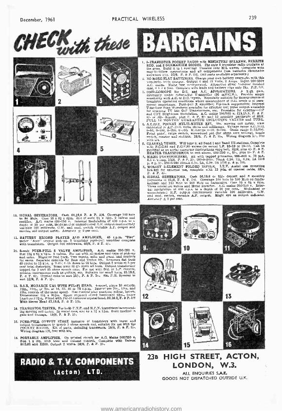
December, 1961 PRACTICAL WIRELESS 739
10. SIGNAL GENERATORS. Cash 64.19.6 P. & P. 5/6. (overage 120 kc/e to 84 Mo /e. Case 10 x 61 x 441n. Sloe of scale 81 x 811n. 2 valves and rectifier. A.C. mains 250 -250 v. Internal modulation of 400 c.p.a to a depth of 30 per cent, modulated or umeodulated R.F. output continuously variable 100 millivolts. C.W. and mod. switch variable A.F. output and moving coil output meter. Accuracy ± 2 per cent.
1t. BATTERY RECORD PLAYER AND AMPLIFIER. 46 r.p.m. 'Star" motor "Aces' crystal pick -up, 3 translator push -pull amplifier complete with transistors. Output 600 milliwatte, 49/8. P. & P. 41-.
12. 8 -watt PUSH -PULL 5 VALVE AMPLIFIER. A.O. main, 200.250 v. Sise 104 x 61 x 29m. 5 valve. For use with all makes and type of pick -up and mike. Negative feed back. Two Inmate, mike and gram. and controls for same. Separate controls for Base and Treble lift. Response Oat from 40 cycles to 15 he /e, ± 2 db; 4 db down to 20 ke/e. Output 8 watts at 6 per cent total distortion. Noise level 40 db down all bum. Output transformer tapped for 3 and 15 ohms speech coil. For use with Std. or L.P. recorde, musical instrumenta such as guitare, etc. Suitable for email balle, 28.19.6, P. & P. 61-. Crystal mike to cuit 15 /-e P. & P. 2/-. 81n. P.M. Speaker te suit 12/O. P. & P. 2/..
16. B.B.R. MONARCH UAS WITH FUL-FI HEAD. 4- speed, Play. 10 recorde, 13in., l0in., or Tin. at 16, 33, 45 or 78 r.p.m. Intermixes 7in.. 10in. and 12in. recorde of the same speed. Has manual play position; colour, brown. Dimensions: 129 x I01ie. Space required above baseboard 49in., below baseboard 211n. Fitted with Ful -Fi turnover crystal head. 9819.6. P. & 2.0/0 With Stereo Head 6719.6. P. & P. 5 /6.
It TRANSISTOR TESTER. For both P.N.P. and N.P.N. transistore Incorporat- ing moving coil meter. In metal case, size 44 e 31 x lOIn. Scale marked in gain and leakage. 19 /8. P. & P. 3/-
15. PUSH -PULL OUTPUT STAGE inclusive of transistors with Input and output transformers to match 3 ohms epeech coil, suitable for use with the POCKET RADIO. Kit of parte, including transistors. 19/6, P. & P. 2/-. Wiring diagram 1 /8, free with kit.
18. PORTABLE AMPLIFIER. On printed cIrcolt for A.O. Maim 200/9150 y. Oise 4 x lin. with tone and volume oontroL Complete with Valves ECIS9 and F280. Output 2 watts. 89/6, P. & P. 3/..
1. 3- TRANSISTOR POCKET RADIO with MINIATURE SPEAKER, FERRITE ROD, and 8 GERMANIUM DIODES. The only 8 translator radio available at the price. Build it in 1 eveningl Tunable over M/L waves. Complete with easy -to- follow instructions and all components (less batteries obtainable anywhere 1/3). 27/8. P. & P. 2/6. (All perte available separately.)
2. NO MORE FLAT BATTERIES. Charge your own battery overnight with this wonderful little charger. Output 6 and 12 Volts, 2 Amps. Input 200 -200v A.C. mein. Mains fuse incorporated. Attractive silver hammer Oniehed case, 8 x 3 x 31ns. Complete with leads and battery clip, only 21e. P.P. 3/6.
3. OSCILLOSCOPE ter D.C. and A.C. APPLICATIONS. A high gain, extremely stable differential Yampffier (90 mV/C.91.). Provide ample sensitivity with A.O. or D.C. Input. Especially meltable for measurements of transistor operating conditions where maintenance of D.C. levels is of para- mount importance. Push -pull % amplifier; Fly -back muppreaelon; Internal Time -basa Bean Waveform available for external use; pules output available for checking TV line 0/P Traneformere, etc. Provision for external-UP and CRT Brightness Modulation. A.C. mains 200/250 v. 615.15.0, P. & P. 8/- or 80 /- deposit, plue P. & P. 8/- and 12 monthly payments of 28/8. FULL 12 MONTHS' UUARANTEE INCLUDING VALVES and TUBE.
4. A.C. /D.C. POCKET MULTI -METER KIT. 21n. moving coil meter, avale calibrated In A.C. /D.C. volts, chine and milhampe. Voltage range A.C.ID.O. 0-50, 0- 100, 0-250, 0-500. Milliampe 0-10, 0 -100. Ohms range 0- 10,000. Front panel, range switch, wlrewound pot (for ohms zero setting), toggle switch, resistor and rectifier. 1910. P. & P. 2/.. Wiring diagram II., free with kit.
5. CHANNEL TUNER. Will tune to all Band I and Band III atatione. Complete with P.C.C.84 and P.C.F.80 valves (In Bernie) I.F. 16-19 or 38 -28. Can be modified as an aerial converter (imtructlone supplied). 82/8, plue 4/. P. & P. HEATER TRANSFORMER to suit above, 200 -260 v., 8 / -, plus 2/- P. & P.
O. MAINS TRANSFORMERS. All with tapped primaries, 260 -500 v. 70 mA, 6.3 v. 2 amp, 10 /8. P. & P. 3 /-. 280 -0-280v. 70m6. 6.3v. 2A, 6.3v. lA 1016 p. & p. 3/ -. 280 -0-280 120mA 6.2v. 2A, 6.3v. 3A 17/6 p. & p. 3/6.
7. WOLSEY 3- ELEMENT FOLDED DIPOLE. LT.V. Aerial less mounting bracket for external use. complete with 12 yds., of coaxial cable. 15 /-, P. & P. 4/-.
9. SIGNAL GENERATORS. Cash 66.19.8 or 25/- depoelt and 8 monthly payments of 21/8, P. & P. 616. Coverage 100 kola to 100 Mcle on funds. mantels and 100 Mcle to 200 Mc /e on harmonica Case 10 x 69 x 04in. Three miniature valves and Metal Rectifier. A.C. mains 200 /250 v. Inter- nal modulation of 400 .p.a to a depth of 30 per cent. Modulated or =modulated R.F. output continuously variable 100 millivolt. C.W. and mod. switch, variable A.F. output. Magic eye as output Indicator. Accuracy ± 2 per cent.
RADIO & T.V. COMPONENTS (Acton) LTD.
23B HIGH STREET, ACTON, LONDON, W.3.
ALL ENQUIRIES S.A.E. GOODS NOT DISPATCHED OUTSIDE U.K.
www.americanradiohistory.com

740 PRACTICAL WIRELESS December, 1961
another NEW instrument from Salford, the
minitest POCKET -SIZED MULTIRANGE TEST SET
A new compact instrument suitable for the measurement of D.C. voltages and currents. A.C. voltages and ohms. Its high sensitivity renders it suitable for testing and fault location in all types of electrical and electronic circuits. It 1a well built to easuré long and satisfactory service. The instrument Is economically priced and supplied with test leads with plug connections at one end. (Leather carrying case available as an extra). RANGES: A.C. Volts. 2.5, 10, 25, 100, 250, 1000.
D.C. Volts. 2.5, 10, 25, 100, 250, 1000.
D.C. Amps. 50 31A, 1mA, 10mA, 100mA, 1A. Ohms. 2000 200,000 20 MA
ACCURACY: D.C. Volts & Amps. ±2% of full scale deflection
A.C. Volts ±3% of full scale deflection ±5% at centre scale.
Send for leaflet MIN /6009 /PW
neat and compact ... with large instrument performance SALFORD ELECTRICAL INSTRUMENTS LIMITED Peel Works Silk Street Salford 3 Lancs Tel: Blackfriars 6688 London Sales Office; Magnet House. Kingsway, W.C.2.. Tel : Temple Bar 4668 A Subsidiary of THE GENERAL ELECTRIC GO. LTD. Of ENGLAND
CODAR "CLIPPER" ALL BAND RECEIVERS 10 -2000 METRES LISTEN TO AMATEURS, AIRCRAFT, SHIPPING, SHORT, MEDIUM, LONG WAVE BROADCAST STATIONS THROUGHOUT THE WORLD.
THE MINI -CLIPPER THE SUPER CLIPPER 88/6 The miniature valve radio with This world -famous hybrid receiver has the BIG SET features. Covers 39 / 6 achieved remarkable successs. Tremen- all Short, Medium, Long waves dous performance with Hi -gain valve 10 -2000 metres (5 coils). Smart detector PLUS two Ediswan transistor all satin silver ali. front panel amplifiers which are supplied assembled, with engraved dials, etc. Ball only 3 wires to connect. Large precision bearing, air spaced variables. fi í dial, 7 x 4in., with 2 pointers, bandset Size only 6; x 33 x 4in. Battery
l and bandspread, dual slow -motion
lasts months. No drilling. Total .. kf drivers, airs aced variables. Punched building cost including punched I.t{.; -- chassis 8 x 5}Pn. Batteries last months. chassis, valve, front panel, one it Covers 10 -2000 metres (5 coils). Total coil for 20 -60 metres, nuts, .x6 "' building cost including chassis, valve, bolts, wire, Step -by -step pic- 2 transistor stages, 2 coils 20-60 and 55 -190 metres. Step -by -step torial plans, 39/6. P. & P. 2/ , pictorial plans, nuts, bolts, wire 88f6. P. & P. 2/6. Plans only, 2f6. Additional coils and electrical bandspread optional extras. THE CLIPPER. As above but one transistor stage, 79f6. P. & P. Parts sold separately. Full plans, parts list, 2/ -. 2,6. Optional Front Panel, Silver Hammer finish, all holes, 6/9.
THE CLIPPER CR 45 16.17.6 This A.C. Mains receiver is the latest model in the famous CLIPPER Series and combines really top
performance with superb professional finish. It is the finest ALL BRAND receiver at the price with a new high gain circuit using ECC81 double triode, EL84 output, EZ80 full wave rectifier. Power output 31 watts for 2/3 ohm speaker. Covers 10 -2000 metres (5 coils). World -wide reception. Outstanding features include 3 planetary slow motion drives, separate electrical bandspread, air spaced low loss variable, satin silver dials, silver hammer front panel. Total building cost, including 10 x 54in. punched chassis, valves, front panel, 2 coils 20 -60 and 55 -190 metres, nuts, bolts, wire, etc., 10 pages pictorial plans, E6.17.6. P. & P. 316. Optional extra. Modern styled Cabinet, rear panel, silver hammer finish, 27/6. Parts sold separately. Full plans, parts list, 10 pages, 316 post free.
No technical knowledge is required to build these fine receivers. Only new guaranteed components are supplied. Send 3d. stamp for illustrated leaflets, testimonials. Suppliers to Educational Authorities, Government Departments, etc. Coming shortly, The Clipper CR 66 A.C. Superhet Communication Receiver.
CODAR RADIO COMPANY, COLEBROOK ROAD, SOUTHWICK, SUSSEX
www.americanradiohistory.com

December, 1961 PRACTICAL WIRELESS
A Dry - Battery Recharger 'll SERS of transistor receivers are not usually
very worried about the cost of battery replace- ments. There is, however. ..ne special disadvantage about dry batteries, namely the inescapable drop in voltage with use, which progressively limits the undistorted output avail- able from the loudspeaker. While certain cells are made which exhibit the property of constant voltage during their life, these are not readily available "over the counter ", and are also decidedly expensive.
Circuit The simple circuit given here is designed to
afford a "topping -up" for dry cells. It can be made up from " spares -box " ccmponents, because nothing is very critical. Fig. 1 is self- explanatory.
The transformer in the author's instrument is an old heater transformer, giving a voltage output of 13.3, with a tapping for 25% boost"; it was previously bought as a cathode ray tube isolating transformer. As an alternative, an old audio output transformer might well be used, as long as a turns ratio between primary and secon- dary of about 20 :1 can be chosen.
The rectifier may be any L.T. rectifier, capable of supplying up to 100mA; or two good selenium elements could be assembled from an old unit.
R1 8200
13V approx.
To +ve terminal on battery
R2 5000
w.w.
To -ve terminal on battery
Ratio 20:1
Fig. 1.-The circuit of the instrument.
D.C. Plus A.C.
The resistor in parallel with the rectifier requires some explanation. Experiments with pure D.C. indicate that with dry cells of the usual Leclanché type, uneven depositing of the zinc occurs, and re- charge results in loss of potential life, and considerable over- voltage after charge with rapid drop in service. The superimposition of A.C., and the fact that no reservoir or smooth- ing circuit is included, enables these difficulties to be avoided. The 50011 variable resistor should be of the wire -wound type. It serves to adjust the charging current to the required value.
741
" TOPPING -UP" TRANSISTOR RECEIVER
CELLS
By N. Mears
In first putting the unit into service, the charging current should be measured. Batteries of the DT9 size may be recharged overnight at at least 50mA, while smaller sizes should receive proportionately less. 1f the resistor R2 is pro- vided with a pointer knob, the type of battery can be indicated on a scale and the control set accordingly when recharging.
Connections
Apart from the obvious precaution of ensuring that the battery is properly connected (best made certain by providing non- interchangeable ter- minal clips) there is little to worry about. It should be noted that it is not practicable to recharge a fully run -down battery, because the zinc will probably be on the point of perforation. However, if, following a few hours' use, a suitable topping -up charge is given, a Lew battery can be induced to give twice its normal life at least, and of course the voltage is maintained at a much better level in use. The writer uses two DTG batteries for alternate weeks, and after 24 weeks the original voltage of both is still found while the receiver is working. There seems little sign that either battery is nearing the end of its life, although, using the receiver four hours daily, the expected life of each would be about six weeks at the current delivered.
The circuit described above was dé igned for 9V transistor batteries. These are probably the most often used, but only a variation in series variable resistor is needed to take account of voltage up to 12 and down to 1-5.
The circuit is not at all suitable for running a transistor receiver direct. even if fitted with a reservoir capacitor and smoothing circuit. S
Russian Delegation at Marconi's
MR. S. A. MIKOYAN and three other members of the Soviet State Aircraft Committee delega-
tion to Farnborough visited Marconi's Aeronautical Division at Basildon recently. The visit was arranged as a result of discussions at Farnborough last week with the Russian delegation, which included the aircraft designers Antonov and llyushin.
The delegation was gown round the Marconi airborne communications and navigational aids laboratories where they were particularly interested in the development of Doppler Navigators for civil aircraft and in the Sixty Series navigation and communication equipment. They were also shown a demonstration of closed circuit television equip- ment which is currently being used in airborne and airport applications.
www.americanradiohistory.com

742 PRACTICAL WIRELESS December, 1961
Tracing Intermittent Faults (F..) Y far the simplest fault to trace is that which causes complete failure of the set. The reason for this is that the fault condition is constant, and that complete failure must mean that there is an absolute and permanent breakdown somewhere in the circuit. The usual technique is to trace back from the speaker to the front of the set in an endeavour to locate the defective component or broken wire. A process of elimination would be used and it would not be very long before the fault were revealed.
Disappearance of Fault When the fault is intermittent, however, the
problem is often complicated since any slight dis- turbance to the circuit may clear the trouble temporarily and cause the set to work normally for a while. It may happen simply by connecting a voltmeter or even by scraping the aerial or earth wire on the socket. It is absolutely pointless to make ordinary tests on the now normal receiver, for all will be found to be in perfect order and it is not always possible to promote the fault con- dition again by circuit disturbance.
The usual exercise is to let the set continue playing out of the cabinet and in an accessible position in the hope that it will go off again so that a further attempt can be made to trace the origin of the trouble. Unless one is very lucky or uses special servicing techniques it may well need many attempts before the fault is eventually located.
There are other intermittent faults such as inter- mittent distortion, crackling and frying which are equally as complex to diagnose unless they are given special attention, but first let us investigate the intermittent failure fault.
Adjust and Listen When it has been established that ordinary test-
ing methods cannot be used because any slight disturbance to the circuit causes the set to burst into life, the set should be left running in its cab- inet and with the back cover in position until it goes off again. When it goes off, quite a lot of information can be obtained without touching the inside of the set at all. First an ear should be held very close to the loudspeaker to detect the normal residual hum which should be present on all sets.
If hum is present, one can be sure that H.T. supply and L.T. circuits are in order; also the speaker and the output stage. If there is no hum,
THE PROCEDURE TO USE WHEN NORMAL METHODS REMOVE THE
FAULT TEMPORARILY
By "Serviceman"
then the problem should not be very difficult to solve. The back cover should carefully be removed and the wires connecting the speaker to the output transformer should be moved about and slight tension applied to them to test the soldered joints at both the transformer and speaker tags. A dry joint on the speaker lead is a strong possibility at this stage.
Testing the Loudspeaker If the trouble persists, it would be .a good idea
to connect a pair of headphones or another speaker across the existing speaker. If reception is now restored, the set's speaker has an intermittent fault which it may or may not be possible to repair.
Ouput valves sometimes go intermittent, which can be tested by tapping the valve sharply with
6
IIUII
,
JN%ì
Fig. 1. -To prevent an intermittent fault from being corrected when test instruments are applied, a signal can be applied from a loop of wire slipped over the
envelope of the valves, as shown.
the handle of a screwdriver. A series of loud crackles followed by normal reception would indicate that valve replacement would cure the trouble. Triode -pentodes, such as the ECL80 class, are particularly prone to this trouble towards the end of their life.
(Continued on page 745)
www.americanradiohistory.com
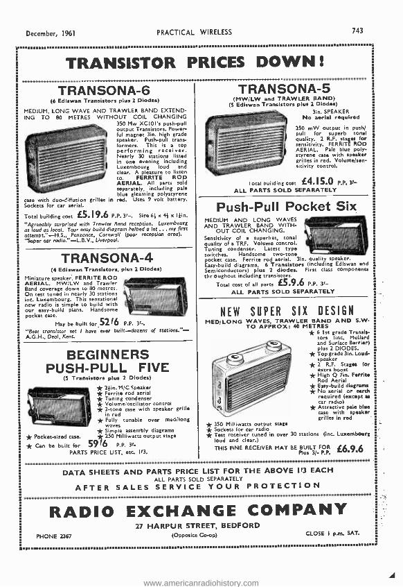
December, 1961 PRACTICAL WIRELESS 743
TRANSISTOR PRICES DOWN! . . . . . . . . . . . . . . . . . . . . .
a
TRANSONA-6 (6 Ediswan Transistors plus 2 Diodes)
MEDIUM, LONG WAVE AND TRAWLER BAND EXTEND- ING TO 80 METRES WITHOUT COIL CHANGING
350 Mw XCIOI's push -pull output Transistors. Power- ful magnet 3in. high grade speaker. Push -pull trans- formers. This is a top performing receiver. Nearly 30 stations listed in one evening including Luxembourg loud and clear. A pleasure to listen to. FERRITE ROD AERIAL. All parts sold separately, including pale blue gleaming polystyrene
case with duo -diffusion grilles in red. Uses 9 volt battery. Sockets for car aerial.
Total building cost £5. 19.6 P.P. 3f -. Size 60x 4} x I }in.
"Agreeably surprised with Trawler Band reception. Luxembourg as loud as local. Your easy build diagram helped a lot ... my first attempt. " -H.S., Penzance, Cornwall (poor reception area). "Super car radio. " -L.B.V., Liverpool.
TRANSONA-4 (4 Ediswan Transistors, plus 2 Diodes)
Miniature speaker. FERRITE ROD AERIAL. MW /LW and Trawler Band coverage down to 80 metres. On test tuned in nearly 30 stations inc. Luxembourg. This sensational new radio is simple to build with our easy -build plans. Handsome pocket case.
May be built for 52 f6 P.P. 3f -.
"Best transistor set I have ever built- dozens of stations." - A.G.H., Deal, Kent.
BEGINNERS PUSH -PULL FIVE
(5 Transistors plus 2 Diodes)
* 2 1in. M/C Speaker * Ferrite rod aerial * Tuning condenser * Volume/oscillator control * 2 -tone case with speaker grille in red * Fully tunable over med /long waves * Simple assembly diagrams * 250 Milliwatts output stage
5916 P.P. 3f-
* Pocket -sized case.
* Can be bulk for PARTS PRICE LIST, etc. Ifa.
TRANSONA-5 (MW /LW and TRAWLER BAND)
(5 Ediswan Transistors plus 2 Diodes) 3in. SPEAKER
No aerial required
250 mW output in push/ pull for superb tonal quality. 2 R.F. stages for sensitivity. FERRITE ROD AERIAL. Pale blue poly- styrene case with speaker grilles in red. Volume /sen- sitivity control.
I osal building cost £4. 15.0 P.P. 3f- ALL PARTS SOLD SEPARATELY
Push -Pull Pocket Six MEDIUM AND LONG WAVES AND TRAWLER BAND WITH-
OUT COIL CHANGING. Sensitivity of a superhet, tonal quality of a TRF. Volume control. Tuning condenser. Latest type switches. Handsome two -tone pocket case. Ferrite rod aerial. 3in. quality speaker. Easy -build diagrams. 6 Transistors (including Ediswan and
Semiconductors) plus 2 diodes. First class components thr oughout including transistors.
Total cost of all parts £5.9.6 P.P. 31-
ALL PARTS SOLD SEPARATELY
InlÌlÑ!IlllllllÌ \
NEW SUPER SIX DESIGN MED /LONG WAVES, TRAWLER BAND AND S.W.
TO APPROX: 40 METRES * 6 1st grade Transis- tors (inc. Mullard and Surface Barrier) plus 2 DIODES. * Top grade 3in. Loud- speaker * 2 R.F. Stages for extra boost * High Q 7in. Ferrite Rod Aerial * Easy -build diagrams * No aerial or earth required (except as car radio) * Attractive pale blue case with speaker grilles in red * 350 Milliwatts output stage * Sockets for car radio * Test receiver tuned in over 30 stations (inc. Luxembourg
loud and clear.)
THIS FINE RECEIVER MAY BE BUILT FOR {6.9só Plus 3/- P.P.
DATA SHEETS AND PARTS PRICE LIST FOR THE ABOVE I/3 EACH ALL PARTS SOLD SEPARATELY
AFTER SALES SERVICE YOUR PROTECTION
RADIO EXCHANGE COMPANY 27 HARPUR STREET, BEDFORD
PHONE 2367 (Opposite Co-op) CLOSE I p.m. SAT.
www.americanradiohistory.com

744 PRACTICAL WIRELESS
WEYRAD December, 1961
IMPROVED COMPONENTS FOR THE 6- TRANSISTOR 2 -WAVE SUPERHET RECEIVER
NEW ROD AERIAL AND DRIVER TRANSFORMER FOR SIMPLER AND HIGHER PERFORMANCE
ROD AERIAL -RA2W 6 in. long, 3/8 in. diameter, connections to tags on Coils, For 208 pF tuning capacity ... ... 12/6 Car Aerial coupling Coil ... 1/- OSCILLATOR COIL- P50 /1AC M.W. covered with 176 pF tuning capacity. L.W. by extra padder ... 5/4 I.F. TRANSFORMERS 1st and 2nd Stage- P50 /2CC ...
3rd Stage- P50 /3CC DRIVER TRANSFORMER -LFDT4 Redesigned to reduce size and improve perform- ance. Six spills for mounting and connections
5/7 (2 Required)
9/6 PRINTED CIRCUIT -PCA1
Size 2% in. x 83/4 in. Ready drilled and printed with component positions ... WE CAN NOW OFFER A CIRCULAR TUNING SCALE PRINTED IN BLACK ON CALIBRATED WITH WAVE- LENGTHS AND STATION NAMES ... CONSTRUCTOR'S BOOKLET WITH FULL DETAILS AND FREE SCALE ...
WEYMOUTH RADIO MANUFACTURING CO., REGENT FACTORY, SCHOOL STREET,
WEYMOUTH, DORSET
GOLD FOIL, PRICE 6d.
2/-
LTD.
THE BEST YET IN RECORDER KITS
FOR BUILDING TWO AND FOUR TRACK MODELS USING
LATEST BSR AND COLLARO DECKS KIT 'A' (4- TRACK) for BSR Monardeck. Assembled
ready for building in. 9 gnu. KIT 'B' (TWO TRACK) for BSR Monardeck Assembled
for building in. 8 gns. Two -tone covered wooden case with speaker for above. 4 gns. KIT 'A' with Deck, Case and Speaker. 24 gns. KIT 'B' with Deck, Case and Speaker 21 gns. KIT 'C' for Collaro Studio Deck (illustrated above). I I gns. Case and Speaker for above 5 gns. KIT 'C' with Case, Speaker and Deck (as illustrated). 28} gns. '"All amplifiers supplied assembled on printed circuit boards with valves.
Hi -fi quality printed -circuit, amplifiers, individually checked Complete with valves, transformers and everything down to wire cut to length Produced by the makers of amplifiers for some of today's best known recorders. The specially designed kits offered here set entirely new standards of performance and finish for the home constructor. Amplifiers, case and speaker assemblies and kits complete with decks are available. Well presented instructions are included. All equipment complete and guaranteed. From radio dealers, or in cases of difficulty please write direct
MARTIN RECORDAKITS
Leaflet free on request. Set of full instructions for any one model 216d. post free. (Allowable on pur- chasing kit).
COUPON BRINGS DETAILS
MARTIN ELECTRONICS LIMITED,-- 155 HIGH ST., BRENTFORD, MIDDX.
Leaflet on Martin Recordakits please. NAME. ....._..____._.._.._.._.___._ ADDRESS
I(In Block Letters.)
www.americanradiohistory.com

December, 1961 PRACTICAL
(Continued from page 742) Although it is unlikely for the H.T. supply to
fail intermittently, a similar, though lighter tap on the rectifier may give some idea of a faulty valve. With early type 5V rectifiers, the filament had a habit of going open- circuit in an old valve when very hot. This would cause a gradual fade -away, however, and would rarely be corrected by circuit disturbance -such trouble can be seen by the fila- ment being out and the valve cold.
500m
IF difference
300m
200m
5OOm
300m
200m
Portable Faulty set
Fig. 2 (MM.-The local oscillator of a suspect set can be checked by operating a portable receiver close to its frequency- changer. When the portable is tuned to a station or carrier, a whistle will be heard when the suspect set's oscillator is tuned to the same frequency. The two tuning points are caused by the I.F. difference in relation to the oscillator frequency. Fig. 3 (right).- Intermittent drop in volume is often caused by trouble in the I.F. capacitors CI and C2. Instability and distortion should lead to a check of
capacitors C3 and C4.
Intermittent faults have been known to occur in smoothing resistors from the rectifier cathode and, in some cases, in smoothing chokes. Generally speaking, when there is no residual hum, the inter- mittent fault is rarely affected by circuit dis- turbance, and normal fault tracing techniques can be adopted during the period that the fault is present.
Signal Circuits Intermittent faults may occur on the signal
alone; for example, a normal residual hum may be present and the set may exhibit the normal hiss which increases in volume as the volume control is turned up. This is almost the same effect as when the aerial is removed from a set which is working correctly, and is a symptom which is really sensitive to circuit disturbance.
If there is a distinct alteration in the level or the tone of the noise at the speaker when the volume control is turned, or if a slight crackling occurs when the control is rotated, then one can be reasonably sure that the whole of the A.F. section of the receiver is working correctly. At
WIRELESS 745
this stage, and with the volume control at maxi- mum, it may pay to turn the wavechange switch through its various ranges. If there are definite " clicks " when the switch is turned from band to band, then there is little doubt that the I.F. stages are also in order.
Unfortunately, the fault at this time may clear, owing to the disturbance caused by operating the wavechange switch. Should this be the case, the back should be put on the cabinet and the set left running until it fails again.
I.F. Stage Check The next time the set goes off a more scientific
approach to the problem will be necessary. A loop of about twenty turns of 26s.w.g. insulated wire should be prepared of suitable diameter to slip easily over the valves. The ends should be twisted together for about a foot or so and connected to the terminals of a dummy aerial, as shown in Fig. 1. The dummy aerial should then be con- nected to the R.F. output terminals of a signal generator in the ordinary way.
Now, when the set goes off, the loop of wire should be slipped over the frequency- changer valve and the generator adjusted to full output at the set's I.F. If the set's I.F. stages are in order, the modulation of the generator signal will be heard from the speaker. In this way it is possible to establish what is right and what is wrong in a set without actually touching or disturbing the circuits. If there is no output here, the loop should be transferred to the I.F. amplifier valve. At this point, the signal output may only be very low and it is essential that the generator is on full output and the set's volume control turned full on. The generator will also need to be tuned accurately to I.F. peak.
If there is output from the I.F. amplifier, but not from the frequency changer, the trouble would obviously be somewhere in the first stage. However, if there is also a strong output from the frequency changer, one can be almost certain that the local oscillator is at fault.
Local Oscillator Check
There is a good way of checking local oscil- lators without touching the suspect set if another radio or small portable is available. When the intermittent set is in one of its "good" conditions, the portable should be held as close as possible to the frequency- changer valve and tuned to a fairly strong station or carrier around 300m (medium - wave). The intermittent set should also be switched to the medium waveband and the tuning adjusted around the 500m mark until a beat note or whistle is heard on the station to which the portable is tuned.
The whistle, of course, is caused by the set's local oscillator beating with the portable's signal. The dial settings will not coincide on the two receivers, since the oscillator frequency is removed from the tuned frequency by the intermediate - frequency, but on most sets the oscillator works at a frequency equal to the tuned frequency plus the I.F. The difference between the two settings is thus the intermediate- frequency, as illustrated in Fig. 2.
When such a beat note has been established, it then remains to wait for the intermittent set to
www.americanradiohistory.com
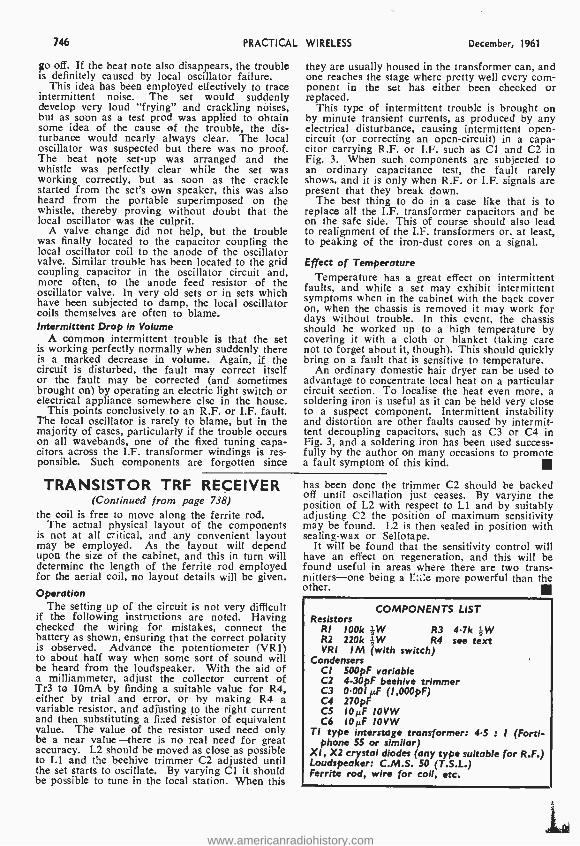
746 PRACTICAL
go off. If the beat note also disappears, the trouble is definitely caused by local oscillator failure.
This idea has been employed effectively to trace intermittent noise. The set would suddenly develop very loud "frying" and crackling noises, but as soon as a test prod was applied to obtain some idea of the cause of the trouble, the dis- turbance would nearly always clear. The local oscillator was suspected but there was no proof. The beat note set -up was arranged and the whistle was perfectly clear while the set was working correctly, but as soon as the crackle started from the set's own speaker, this was also heard from the portable superimposed on the whistle, thereby proving without doubt that the local oscillator was the culprit.
A valve change did not help, but the trouble was finally located to the capacitor coupling the local oscillator coil to the anode of the oscillator valve. Similar trouble has been located to the grid coupling capacitor in the oscillator circuit and, more often, to the anode feed resistor of the oscillator valve. In very old sets or in sets which have been subjected to damp, the local oscillator coils themselves are often to blame. Intermittent Drop in Volume
A common intermittent trouble is that the set is working perfectly normally when suddenly there is a marked decrease in volume. Again, if the circuit is disturbed, the fault may correct itself or the fault may be corrected (and sometimes brought on) by operating an electric light switch or electrical appliance somewhere else in the house.
This points conclusively to an R.F. or I.F. fault. The local oscillator is rarely to blame, but in the majority of cases, particularly if the trouble occurs on all wavebands, one of the fixed tuning capa- citors across the I.F. transformer windings is res- ponsible. Such components are forgotten since
WIRELESS December, 1961
they are usually housed in the transformer can, and one reaches the stage where pretty well every com- ponent in the set has either been checked or replaced.
This type of intermittent trouble is brought on by minute transient currents, as produced by any electrical disturbance, causing intermittent open - circuit (or correcting an open- circuit) in a capa- citor carrying R.F. or I.F. such as Cl and C2 in Fig. 3. When such components are subjected to an ordinary capacitance test, the fault rarely shows, and it is only when R.F. or I.F. signals are present that they break down.
The best thing to do in a case like that is to replace all the I.F. transformer capacitors and be on the safe side. This of course should also lead to realignment of the I.F. transformers or, at least, to peaking of the iron -dust cores on a signal.
Effect fiect of Temperature Temperature has a great effect on intermittent
faults, and while a set may exhibit intermittent symptoms when in the cabinet with the back cover on, when the chassis is removed it may work for days without trouble. In this event, the chassis should be worked up to a high temperature by covering it with a cloth or blanket (taking care not to forget about it, though). This should quickly bring on a fault that is sensitive to temperature.
An ordinary domestic hair dryer can be used to advantage to concentrate local heat on a particular circuit section. To localise the heat even more, a soldering iron is useful as it can be held very close to a suspect component. Intermittent instability and distortion are other faults caused by intermit- tent decoupling capacitors, such as C3 or C4 in Fig. 3, and a soldering iron has been used success- fully by the author on many occasions to promote a fault symptom of this kind.
TRANSISTOR TRF RECEIVER (Continued from page 738)
the coil is free to move along the ferrite rod. The actual physical layout of the components
is not at all critical, and any convenient layout may be employed. As the layout will depend upon the size of the cabinet, and this in turn will determine the length of the ferrite rod employed for the aerial coil, no layout details will be given.
Operation The setting up of the circuit is not very difficult
if the following instructions are noted. Having checked the wiring for mistakes, connect the battery as shown, ensuring that the correct polarity is observed. Advance the potentiometer (VRI) to about half way when some sort of sound will be heard from the loudspeaker. With the aid of a milliammeter, adjust the collector current of Tr3 to IOmA by finding a suitable value for R4, either by trial and error, or by making R4 a variable resistor, and adjusting to the right current and then substituting a fixed resistor of equivalent value. The value of the resistor used need only be a near value -there is no real need for great accuracy. L2 should be moved as close as possible to LI and the beehive trimmer C2 adjusted until the set starts to oscillate. By varying CI it should be possible to tune in the local station. When this
has been done the trimmer C2 should be backed off until oscillation just ceases. By varying the position of L2 with respect to LI and by suitably adjusting C2 the position of maximum sensitivity may be found. L2 is then sealed in position with sealing -wax or Sellotape.
It will be found that the sensitivity control will have an effect on regeneration, and this will be found useful in areas where there are two trans- mitters -one being a li; :e more powerful than the other.
COMPONENTS LIST Resistors
RI 100k ;W R3 4.7k W R2 220k ? W R4 see text VR1 IM (with switch)
Condensers CI 500PF variable C2 4 -30PF beehive trimmer C3 0.001 µF (1,000pF) C4 270pF C5 101iF IOVW C6 10µF IOVW
TI type interstage transformer: 4.5 : I (Forti- phone 55 or similar)
XI, X2 crystal diodes (any type suitable for R.F.) Loudspeaker: C.M.S. 50 (T.S.L.) Ferrite rod, wire for coil, etc.
www.americanradiohistory.com

December, 1961 PRACTICAL WIRELESS 747
OPEN: Tottenham Court Rd., 9 a.m. to 6 p.m. Mon. to Fri., Sat. I p.m. Holloway Rd. and Cam-
Thurs. l: 9 a.m. to p.m. daily.
1 Sat. H.P.
p.m. Our Advantageous H.P and Credit Sale Terms are avail - able on any single item over E5. Your enquiries invited. Please print your name and address.
THE COMPONENT s C LY N E RADIO LTD. SPECIALISTS
18 TOTTENHAM COURT ROAD, W.I. MUSeum 5929/0095 162 HOLLOWAY ROAD, LONDON N.7 NORth 6295/6/7 9 CAMBERWELL CHURCH STREET, S.E.5 RODney 2875
All post orders and correspondence to 162 HOLLOWAY ROAD, LONDON N.7
NEW! NEW! THE "C L Y M A X"
At last a 6- transistor pocket size superhet for Medium and Long Wave at a price YOU Can 1/: afford. All (3 /,1,; required components
".' ' i - -' ,
- - -
ONLY 4.n ,..-
}6a1 6.6 binD more w
uy Plus 2/6 P. & P. * Completely self contained. No external
aerial or earth required. * Full medium wave coverage, plus switched
Light programme on Long Wave. * Push pull output -250 milliwatts. * Matched set of latest type Mollard Wangle- tors. * Genuine 3ín. P.M. Speaker, * High-Q Coila,
* Ferrite rod aerial with high selectivity. * Size: 51 z 31 a liIn. Two tone cabinet. * Precision etched printed circuit with
oomponent references clearly marked. Alignment servloe available. All parts available separately. Full assembly instruo- Lions and individually priced parta Het. 2/- post free.
"POPULAR FOUR"
_. , ......... l
,
..,.... °f`°s.,.+1 `
- < °
-
IMPROVED APPEARANCE AND PERFORMANCE
lcontact-cooled cavbe. NDe ovalve aa New T.R.F.
e Luxe Cabinet polished walnut finish, cream trim. attractive horizontal dial (as illustrated). Quality Sin. P.M. speaker. Specially wound high gain super -sensitive Denco oolls. Medium and Long Wavebands. Excellent Continental reception! Overall dim- anions: 12ín. x 6ín, a bin. A.C. 200/ 250 v. Simple construction with guaranteed results. Easy to follow practical and theoretical diagrams supplied. All necessary components, down to the last nut and bolt, are offered at a SPECIAL INCLUSIVE
,PRICE OF £5.5.0, phis 3/6 p. & P. Instruction book available separately 1/8. post free. ALL PARTS AVAIL- ABLE SEPARATELY.
"PM. TUTOR" COMPLETE KIT AS SPECIFIED
Stages 1-4 65/- plus 2/- P. & P. All parts available separately
Send stamp for list.
OUTSTANDING METER IMPORT! 20,000 ohms
MODEL 200H Volt-
&
a
_> :
, a , <a <,: ,*
<.. ° -^
A fully guaranteed pocket size: 41' z 31' x l')
per volt !
ohm- Milliametsr Ranges: A.C. Vol -
110.00010, 50
1letr volt). D.C. Vol - tae: 5-25 50. 250. 500. and í5k. (20.000 ohms per volt). D.C. Cur- rent: 0-50 micro- amps. 0-2.5 m /a. 0-250 m /a. Resis- Lance: 0-6k, 0-8 meg. (300 ohm and
d scale). Camel-
an e: 10 P to
.001 1 told. Dec! -
tots 1 tol to +73 dB. size meter (actual
knife edge pointer. test top quality supplied Complete with
prods and full operating instructions at £6.19.6 ONLY. Post Free Optional extra. Attractive carrying case 6/- only. (BOns- fide trade enquiries invited. available. JUST ARRIVED! MOD TE10. Identical in appearance and size with rotary type switch but 10,0000 /v. Ranges: D.C. Voltage: 0-6-30-1204303-1200 volts (10.000 ohms per volt). AC. voltage: 0- ö,90- 120-6i00 -1200 volts (10.000y0
ohms mÄ Resistance: . D CCrren :0,120 icr azn ohm and 15 k at centre scale). Capacitance: 50 pF to 0.01 turd.. 0.001 mfd. to 0.16 mfd. Decibels: -20 to +63 dB in 6 ranges. PRICE 26.18.6. Post Free.
SPECIAL NOTE! Owing to mandate. Curers' reductions of transistor prices we are now able to offer our trim- sistor sets at new low prices!
STOP PRESS! The well known Brayhead Trans Tronlc "SUPER 60" Radio Kit. A complete con- atruction kit to make your own transistorised Transmitter and Re- cefver. No soldering reqd. 7 different circuits to build. Ideal Xmas Gilt-
THE "WAYEMASTER" 7-TRANSISTOR LUXURY PORTABLE
NEW LOW PRICE E9.í9.6
400 Mllliwatt '' - v.. p
Output .f{
To ( !h
- Yourself Medium` Ì,.. '' and Long ;
Wavea- Push -Pull -..,,, Superbet A V. C. Perfect Car Radio I reception " -- °' Size 101n. a eí1n. x Min. at base -..,..,..s. tapering to 4ín. at top. Very attractive two -tone
gold Vynide covered cabinet with black and
knobs handleeand cabinet finings * We ght- with long -life 74 v. battery -41 lb. * Millard high -grade transistors throughout. * High -Flux lin. x 4in. Elliptical Speaker. * Slow motion tuning. * Co-axial socket at rear for direct connection to Car Radio Aerial * Improved reception by use of seven -section plates telescopic aerial disappearing luto Cabinet when closed. 34ín. above Cabinet when fully extended. Construction simplified by Bakelite chassis board with the following componente already mounted: I.F. Transfor- mers (3). Oscillator Coil, Trimmer Bank. Out- put Transformer. Interstage Transformer. Aerial Brackets and Earth Bar. SPECIAL INCLUSIVE PRICE for all required compo- nents. Full assembly Instructions- nothing more to buy -is 69.19.6, plus 3/6 P. & P. Alignment service available. Full assembly Instructions and individually priced parts list, all of which are available separately, 2/6. Post Free.
beautifully Presented in original manufacturers coloured boa with all necessary instructions. (As nation- auY advertfaed at £5.4.8). Limited quantity only at 49/6 Plus P. & P. 4/ -.
"BRAND FIVE" Recording Tape.
High Quality @G m tlenthusiast's 6 1/7 Acetate Base: ). >..,_ 6' 600ft.. 16/-: 5' 900ft. 18 /8 51' 1200ft. 23/8:
Extra 1,200ft. 25/-; r
1,800f't. 35/- Extra Quality Mylar Dupont: 3' 3110ft. 13/ - 5' 1.2001í. 37/6; 7. 1.800ft. 44/ -: 7' 2,400ft. 60 / -. Each on plastic spool. All post tree. BRAND NEW -NOT SUB -STAN- DARD PLASTIC TAPE SPOOLS- Best quality lin. 1/6: bin. 2 / - 51ín. 2/3 7in. 2 /6. PLASTIC SPOOL CONTAINERS for spool sizes Sin.
it m plus 6á.'P71& P. /Totá ov AFL Post free.
"The CITIZEN" NEW LOW PRICE 85/-
Our Sensitive 5 Stage (4 trap a f a t o r plus - ...c" diode) pocket -, 7 transistor re- -- ,-.'.... </ cefver, for full medium wave /.; reception with the fol lowing out - `: =:, 14s3 p standing tea. , * Completely self -contained -No external aerial or earth required. * Genuine Min. High Flux P.M. Speaker. * Push -pull Output -250 milliwatts. * Genuine Mullard Iran- stators. * Socket provided for personal listening. * Socket provided for connection to Car Aerial. * Volume Control with on/off switch- Condenser tuning. * Easy assembly on pre -tagged circuit board. * Attractive red polystyrene cabinet measures Mx 3 z lila. chrome handle, attractive diaL All required components including full instructions. solder. etc.. and battery at special inclusive price of only SO/. (Yes. Eighty -Five Shillings Only!) Plus 2/6 P & P. Nothing more to spend. Suitable crystal deaf -aid type miniature earpiece fitted with miniature lack plug at 7/6 extra only) if req. All parts available separately -itemised list and full assembly instructions sent for 1/6 post free. Hear this amazing little receiver working. at any of our branches.
` "':, : "
F'
}?; ;:, ?::.o;;
' '`' Each plus ditioned plus 1/6 petitively stook. Ask
., EXTENSION _
1 " «:. <: SpEAKER CABINETS
.: New design in 'r 3;a. light oak. Two
£I'. sizes available. > <- For 61' or 8'
..;, speaker at a > <:^ < 22/6. For 10'
speaker at 85/- only.
2/6 P. & P. Suitable recon- 8' P.M. unit at 13/6 only. P. & P. Full range of core-
priced new speakers In for list.
www.americanradiohistory.com
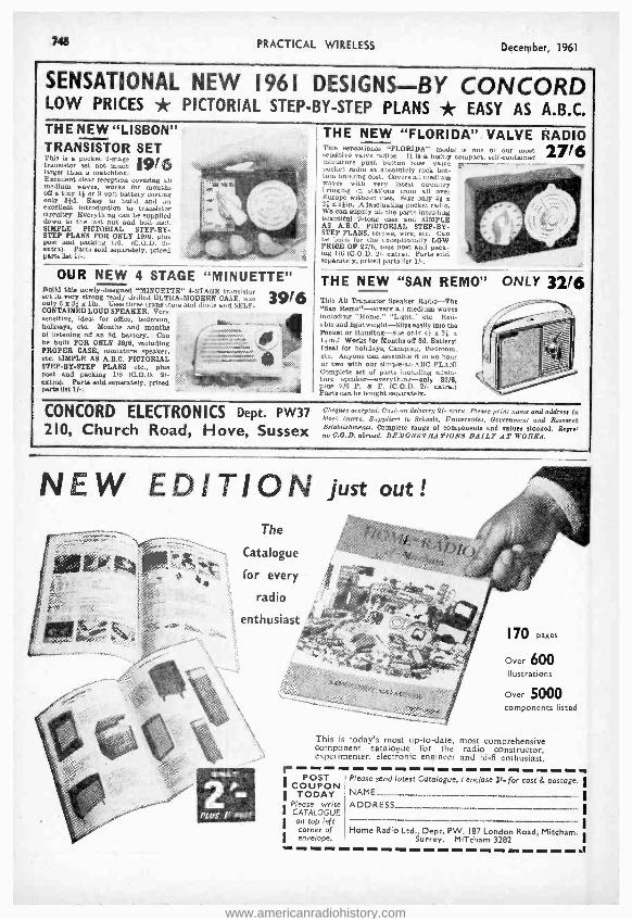
748 PRACTICAL WIRELESS December, 1961
SENSATIONAL NEW 1961 DESIGNS -BY CONCORD LOW PRICES * PICTORIAL STEP -BY -STEP PLANS * EASY AS A.B.C. THE NEW "LISBON" TRANSISTOR SET This is a pocket 2-stage 19/6 transistor et not much r larger than a matchbox. Excellent clear reception covering all medium waves, works for mouths
off a tiny or 3 volt battery costing only 31d. Easy to build and a excellent introduction to transistor circuitry. Everything can be supplied down to the last not and bolt incl. SIMPLE PICTORIAL STEP -BY- STEP PLANS FOR ONLY 19/6, piss mist and packing 1,6. (C.O.D. 2 /- extra). Parts sold separately, priced parts list 1 / -.
OUR NEW 4 STAGE "MINUETTE" Build this newly- designed "MINUETTE" 4 -STAGE transistor 396 set in very strong ready drilled ULTRA- MODERN CASE. aie only 6 x 31x lin. Uses three transistors and diode and SELF - CONTAINED LOUD SPEAKER. Very sensitive, ideal for office, bedroom, holidays, etc. Months and months .^' ' of listening off an 8d. battery. Can be built FOR ONLY 39/6, including PROPER CASE, miniature speaker, 'ï etc. SIMPLE AS A.H.C. PICTORIAL STEP -BY -STEP PLANS etc., plue Post and packing 1/6 (C.O.D. 2/- extra). Parts sold separately, priced parte list 1/ -.
THE NEW "FLORIDA" VALVE RADIO This sensational "FLORIDA" model is one oi our In, sensitive valve radios. It is a highly compact, self -contamed miniature push button base, valve s -- pocket radio at absolutely rock bot- tom building cost. Covers all medium waves with very latest circuitry Fringing in stations from all over Europe without fuss. Size only 41 x 21 al *in, Afascinating pocket radio. We can supply all the part including beautiful 2 -tone case and SIMPLE AS A.B.C. PICTORIAL STEP -BY- STEP PLANS, screws, wire, etc. Can be built for the exceptionally LOW PRICE OF 27/6, plus post and pack ing 1/6 (0.0.D. 2/- extra). Parts sold separately, priced parts list 11..
27/6
THE NEW "SAN REMO" This All Transistor Speaker Radis -The "ban Remo " -covers all medium waves including 'Home," "Light,-' etc. Reli- able and lightweight -Slips easily into the Pocket or Handbag -size only 45 x 21 .x
1 1.1n! Works for Months off 8d. Battery! Ideal for holidays, Camping, Bedroom, etc. Anyone can assemble it in an hour or two with our simple -as -ABC PLANI Complete set of parts including minia- ture speaker-everything -galy 32/6, pins 2/6 P. de P. (C.O.D. 2/- extra.) Parts can be bought separately.
ONLY 32/6
CONCORDELECTRONICS De. P W 37 Cheques accepted. Cash on delivery 21. extra. Please print Tame and address 1.71
P ' block letters. Suppliers to Schools, Universities, Government and Reseal,/
210 Church Road Hove Sussex Eelabltshmenu. Complete range of somponanG and values stocked Reger' f f f rw O.O.D, abroad. DRMONSTRd TIONS DdILP dT WOR%S.
NEW EDITION just out! The
Catalogue
for every
radio
enthusiast
PLUS /' "POST
-., ti'.,-;,:,?:v:>,.-.,áG:i
170
Lpages Over 600 illustrations
Over 5000 components listed
This is today's most up -to -date, most comprehensive component catalogue for the radio constructor, experimenter, electronic engineer and hi -fi enthusiast. r
POST I COUPON
TODAY Please write
I CATALOGUE 1 on top left
corner of I envelope.
Please send latest Catalogue. I enclose 31- for cost & postage. I NAME
ADDRESS I
Home Radio Ltd., Dept. PW. 187 London Road, Mitcham, Surrey. MITcham 3282
I
www.americanradiohistory.com

December, 1961 PRACTICAL WIRELESS 749
Letters to the Editor The Editor does not necessarily agree with the opinions expressed by his correspondents
Whilst we are always pleased to assist readers with their technical difficulties, we regret that we are unable to supply diagrams or provide instructions for modifying commerical or surplus equipment. We cannot supply alternative details for receivers described in these pages. WE CANNOT UNDERTAKE TO ANSWER QUERIES OVER THE TELE- PHONE. If a postal reply is required a stamped and addressed envelope must be enclosed with the coupon from page iii of cover.
B.B.C. TELEVISION RECEPTION
SIR, -I have seen one or two letters recently about listeners picking up television on wavelengths
far removed from the actual transmission, and I would like to offer a suggestion. I have experienced a similar fault, and in some cases it has been direct radiation from a badly adjusted receiver, but in most cases I have investigated it was mains borne. Why the signal should get into the mains I cannot say, unless the mains wiring acts as some sort of aerial, but the fitting of one of the special suppressed plugs into the mains outlet will generally prevent the trouble. Naturally, any aerial which a listener uses should be erected well clear of any television aerial. -F. BAILEY (Willesden).
VINTAGE MODELS
SIR, -How I agree with Mr. Newman (July issue) concerning the reproduction from an old
receiver. I do really think that if anyone could recover one of these old sets from a loft or some other place where it has for long been deposited, and get it going again at correct voltages, etc., one would be agreeably surprised at the per - formance. After all, we rely now mainly on higher efficiency valves for the performance which we obtain, whilst in the older days circuity was, in my opinion, of much more effect. We had very large coils with a minimum capacity across them, and I feel sure that the response from these efficiently tuned circuits was capable of much wider frequency bands than we get in modern apparatus. Has not F.M. been forced upon us because owing to the modern valvés and circuits which they call for cut -off resulted at both ends of the scale? I would very much like to hear one of these old sets cleaned up and put to work on a modern transmission. -J. MANSELL (Warwick).
ADDING COMMUNICATION FEATURES
SIR, -The receiver series under the above title has been most interesting, but I do not think
that the addition of the arrangement described will provide a reader with a real communications set. I have used two or three American communi- cations receivers and I feel that much of their efficiency is due to the coils and associated circuitry. I have not seen any English sets with the same types of coils, ceramic formers, silvered wire and reliable switching. Is it that the condi-
tions in America are so poor that the receivers have been developed to make the most of those conditions and as a result are more efficient than those developed in this country? -E. R. Le PAGE
(S.E.15).
AMATEUR TRANSMITTING LICENCES
SIR, -- Considerable interest has been expressed during recent years by readers on the possi-
bility of the provision of a low power transmitting permit, other than the current Radio Amateur's Transmitting Licence. Whilst it would not appear likely that any form of Novice Licence will be permitted, which frankly could lead to a lot of misguided tinkering with obsolete ex- government transmitters on our already overcrowded L.F. amateur frequency bands, 'there would appear to be a case for the consideration of a Citizen's Radio Permit similar to that in current operation in the U.S.A. For the benefit of readers who have not previously encountered mention of Citizen's Band Radio, it operates basically as follows; initially in 1949, class A and B Citizen's Radio Licences were originally issued by the FCC for the use of frequencies at UHF, but this did not become popular for the average man in the street for his two -way radio, house to car, fishing boat to shore camp, across town office to home, etc., mainly due to the cost of VHF equipment and very restricted line of site transmission range. However, in 1958 the class D Citizen's Radio Service was inaugurated whereby any American citizen over the age of 18 years could obtain a licence upon application, free of charge, without any form of test, simply by filling in the appro- priate form and making postal application to the FCC providing the station is to be used for any legitimate purpose, i.e., private, social, or business communication with other similar stations. Trans - missiogs to take place in the authorised frequency band 26,965kc/s to 27,255 kc /s on any of 23
specified crystal controlled channels spaced 10kc /s apart. (VFO operation not permitted.) Ground wave working only is allowed; attempts to work DX are illegal, as also are CQ calls.
FCC regulations govern the design of equip- ment, most of which takes the form of low cost transceivers, crystal controlled, maximum legal power input 5W, A.M. phone only, frequency tolerance of 0.005 %. The simplest of these con- sist of single channel crystal controlled TX with super -regenerative receiver section, ranging to the more elaborate multi- channel switched tuned TX with double super crystal controlled receiver. Both mobile and home based stations equipment being available. Kits of parts with pre -wired frequency determining sections being also available for the boys who brew their own rigs. Typical operatin- ranges are reported as follows:
www.americanradiohistory.com
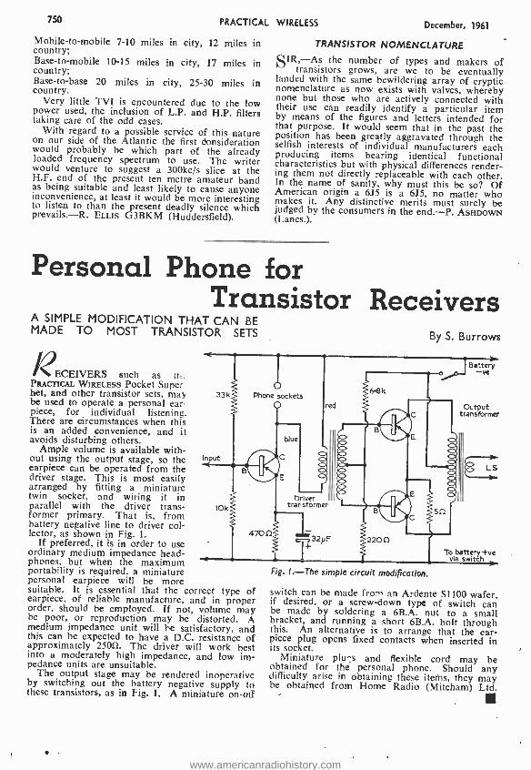
750 PRACTICAL
Mobile -to- mobile 7 -10 miles in city, 12 miles in country; Base -to- mobile 10 -15 miles in city, 17 miles in country; Base -to -base 20 miles in city, 25 -30 miles in country.
Very little TVI is encountered due to the low power used, the inclusion of L.P. and H.P. filters taking care of the odd cases.
With regard to a possible service of this nature on our side of the Atlantic the first donsideration would probably be which part of the already loaded frequency spectrum to use. The writer would venture to suggest a 300kc /s slice at the H.F. end of the present ten metre amateur band as being suitable and least likely to cause anyone inconvenience, at least it would be more interesting to listen to than the present deadly silence which prevails. -R. ELLIS G3BKM (Huddersfield).
WIRELESS December, 1961
TRANSISTOR NOMENCLATURE
SIR, As the number of types and makers of transistors grows, are we to be eventually
landed with the same bewildering array of cryptic nomenclature as now exists with valves, whereby none but those who are actively connected with their use can readily identify a particular item by means of the figures and letters intended for that purpose. It would seem that in the past the position has been greatly aggravated through the selfish interests of individuai manufacturers each producing items bearing identical functional characteristics but with physical differences render- ing them not directly replaceable with each other. In the name of sanity, why must this be so? Of American origin a 6J5 is a 6J5, no matter who makes it. Any distinctive merits must surely be judged by the consumers in the end. -P. ASHDOWN (Lancs.).
Personal Phone for Transistor Receivers
A SIMPLE MODIFICATION THAT CAN BE MADE TO MOST TRANSISTOR SETS
RECEIVERS such as it,. PRACTICAL WIRELESS Pocket Super het, and other transistor sets, may 33k be used to operate a personal ear- piece, for individual listening. There are circumstances when this is an added convenience, and it avoids disturbing others.
Ample volume is available with- out using the output stage, so the earpiece can be operated from the driver stage. This is most easily arranged by fitting a miniature twin socket, and wiring it in parallel with the driver trans- 10k former primary. That is, from battery negative line to driver col- lector, as shown in Fig. 1.
If preferred, it is in order to use ordinary medium impedance head- phones, but when the maximum
Input
By S. Burrows
Phone sockets
470f1
r
red
á8k
Driver transformer
-
"
T32
pF 220f]
portability is required, a miniature personal earpiece will be more suitable. It is essential that the correct type of earpiece, of reliable manufacture, and in proper order, should be employed. If not, volume may be poor, or reproduction may be distorted. A medium impedance unit will be satisfactory, and this can be expected to have a D.C. resistance of approximately 25052. The driver will work best into a moderately high impedance, and low im- pedance units are unsuitable.
The output stage may be rendered inoperative by switching out the battery negative supply to these transistors, as in Fig. 1. A miniature on -off
Battery -ve
Output transformer
LS
To battery +vs via switch
Fig. 1. -The simple circuit modification.
switch can be made from an Ardente S1100 wafer, if desired, or a screw -down type of switch can be made by soldering a 6B.A. nut to a small bracket, and running a short 6B.A. bolt through this. An alternative is to arrange that the ear- piece plug opens fixed contacts when inserted in its socket.
Miniature plus and flexible cord may be obtained for the personal phone. Should any difficulty arise in obtaining these items, they may be obtained from Home Radio (Mitcham) Ltd.
www.americanradiohistory.com

December, 1961 PRACTICAL WIRELESS 751
* POST HASTE * TRANSISTORS REDUCED PRICES
MULLARD HAVE REDUCED THE PRICE OF MANY TRANSISTORS to
0C44 III- 0071 616 0076 81-
0C45 101- 0072 81- 0078 81-
0070 616 OC75 81- 0081 81-
THESE ARE THEIR NEW LIST PRICES WHY BUY SURPLUS?
MATCHED PAIRS of the above listed transistors, Mullard match only the 0072 at 161- pair.
"PRACTICAL WIRELESS" POCKET SUPERHET
OSMOR printed circuit version. Osmor Rod Aerial 101 -, I.F.T.s and Osc: Coils, 2216. Osmor Driver, I I16. Osmor Output, 1016.
Set MULLARD transistors, 5316. 0A81 Diode, 31 -. J.B. Gang, I11 -. Trimmers, 218 pr. Set Condensers, I51 -. Set Resistors, 616.
Ardente Vol. Control, 81, Ardente WIC, 316. Speaker, 19110.
Hardware, 416. Printed Circuit, 91 -. Case and Knob, 716. Dial, 6d. Battery PP4, 21 -. Leaflet giving full illustrated details, 119.
All the above components if purchased at one time 49.9.0. OSMOR undertake to align this receiver for a charge of 101 -.
"WEYRAD" WEYMOUTH RADIO 6 Transistor Superhet using the P50
coils, as they advertise in this journal. P50 /IAC Osc: Coil, 514. P50 /2CC 1st and 2nd I.F.T.s, 517 ea.
P50 /3CC 3rd LF.T., 61 -. RA2W Rod Aerial, 1216. LFDT2 Driver, 916. PCAI Printed Circuit, 916. Instruction Book, V , Set Resistors, 7'6. Vol. Control D.P., 516. Set Condensers, J.B. Gang, I11 -. Beehive Trimmers, 113 ea. WIC, 316. Dial and Knob, 316. Battery PP11, 516. OA81, 31 -. Sec MOLLARD transis- tors, 5316. 35 ohm Sin. round L /S,
JASON F.M. TUNER KITS We are the Authorised Jason Dealer and the whole kit is as
supplied by them. You can therefore safely return to Jason for alignment without them rejecting it for non -standard components. We can also align for the standard charge.
FMTI Is the standard variable tuner for cabinet mounting, unpowered. Supplied complete with four EF91 valves 16.17.6 Hire purchase deposit E1.7.6 and 6 monthly ¿1.1.8
FMTI Power pack ready drilled chassis complete /2.12.6 FMT2 Is a new tuner in a modern case, green, which
can be used for shelf or cabinet mounting, and has the space for power supplies if required Supplied complete with four EF80 valves 17.17.6 Hire purchase deposit 11.11.6 and 6 monthly E1.4.4
FMT2 /With power. Complete kit 19.15.0 Hire purchase deposit EI.19.0 and 6 monthly E1.9.4
FMT3 Is the fringe version and should be used when farther than 70 miles from the transmitter Supplied complete with 6 valves 19.12.6 Hire purchase deposit 11.18.6 and 6 monthly E1.9.0
FMT3 With power. Complete kit 412.0.0 Hire purchase deposit E2.8.0 and 8 monthly E1.6.6
The instruction book is included in all kits, but otherwise 2/6.
JASON SWITCHED TUNERS The JTVI2 and Mercury 2 are both of the pre -set station type with the addition of BBC and ITA sound. They use the latest "Fireball" turret and the A.F.C. ensures freedom from drift. The Mercury 2 is for cabinet mounting with external power, the ITV /2 has the same tuning heart, with power supplies mounted in a case, and can be used for shelf or cabinet. JTV /2 Complete with valves and book /14.15.0
Hire purchase deposit 13.0.0 and 12 monthly EI.1.6 Mercury 2 complete with valves and book /10.15.0
Hire purchase deposit E2.3.0 and 8 monthly EI.4.0 Power pack kit for Mercury 2 ready drilled chassis 12.12.6
Instruction book for switched tuners 41 -.
REQUIRED CHANNELS MUST BE SPECIFIED FOR SWITCHED TUNERS
A more detailed list can be sent upon request.
ALL JASON TUNERS ARE ON DEMONSTRATION, AND ALWAYS IN STOCK.
* POST FREE * MARTIN RECORDAKITS
We are able to offer for the first time, a proprietary range of
Recorders in kit or assembled form. This enables you to take advantage of mass production techniques and prices, should you wish to assemble yourself. The components used are the finest available, with BVA valves, and the decks are the latest having all the improvements B.S.R. and Collaro make from time to time, Heads, etc.: The amplifiers are packed in special cartons with instructions which enable anyone to build. We are confident you will find these Recorders very good value, they have been built up to a
standard and not down to a price. B.S.R. TD3 Monardeck, latest model 5 }in. spools
CASH Hire purchase deposit EI.19.0 and 6 monthly
Tape Amplifier for B.S.R. deck, printed circuit ready wired, with ECC83, ECL82, EM85 and EZ81. Complete with all plugs, sockets, panels, knobs, etc. The whole amplifier mounts on to the deck, making a self contained unit.
CASH PRICE Hire purchase deposit 11.14.0 and 6 monthly
Cabinet for above including 7 x 4M. speaker Total kit as above. CASH Hire purchase deposit 14.10.0 and 12 monthly
The above recorder can be supplied complete with Mic: cape assembled and tested for CASH
PRICE Hire purchase deposit E5.0.0 and 12 monthly
Collaro Studio Deck. Very latest model 3 speeds Hire purchase deposit /2.10.0 and 8 monthly
Tape Amplifier for Studio deck, with ready wired printed circuit, control and input panels, mains and output trans., complete with knobs, plans, screws, etc., EF86, ECC83, EM84, 0A81 and 2 EL84, 3 watts output. Magic eye, Radio and Mic- inputs. Superimposing facilities, EX LIS socket, Low level output, tone control. Can be used as an amplifier.
COMPLETE CASH Hire purchase deposit E2.7.0 and 8 monthly
Cabinet for above including 9 x Sin. speaker Total kit as above. CASH Hire purchase deposit E6.0.0 and 12 monthly
We can supply the above recorder, complete with tape and Mic., in a DE LUXE cabinet, assembled for E35. 0.0
THIS MACHINE IS LISTED 141.0.0 BY MAKERS AND IS A VERY GOOD BUY. Hire purchase deposit E7.0.0 and 12 monthly ¿2.11.4
Microphone for the above recorders, Acos MIC 40, 251 -. SIC plug, 416.
Synchrotape Sin. 600ft. 151- Sin. 900ft. 1916
Finest 51in. 850ft. 1916 5 *in. 1200ft. 2216 Boxed 7in. 1200ft. 2216 7in. 1800ft. 3216
Tape Recorder Speaker Cabinet, corner, 20 x IOin. High class finish in two -tone Grey 'Vynair' With 9 x Sin. high flux speaker
F.M. Tuner Aligned and assembled, using Philips tuning head with ECC85, EF85, EF85, EZ8I and EM81, with 2 diodes. SELF POWERED. UNREPEATABLE BARGAIN. CASH
GRAMOPHONE EQUIPMENT
E9. 9.0 41. 8.4
L8. 8.0 EI. 5.8 E4. 4.0
E22. 0.0 E1.12.1
425. 0.0 (1.16.8
E12.10.0 E1. 7.6
E11.11.0 EI. 5. 6
E5. 5.0 E29. 0.0
E2.2.0
B.S.R. UAI4 TC8 /H cartridge Hire purchase deposit 11.11.0 and 6 mthly
Collaro C60 Autochanger "O" cartridge Hire purchase deposit 11.15.0 and 6 mthly
Garrard "Autoslim" GC8 cartridge Hire purchase deposit EI.17.4 and 6 mthly
E2.15.0 E4. 0.0
E7.19.6
E7.15.0 LI. 4.0 E8.15.0 E1. 6.8 E9. 3.4 EI, 7.8
A.M. RADIO CHASSIS 2 -Band Superhet AC /DC, 4 valves, with speaker.
Size 6 x 9 x 6in. Long and Medium waves 15.17.6 4- Station Pre -set chassis with speaker. Valve line
up and size as above 14.17.6
WE PAY ALL POSTAGE AND INSURANCE ALL ORDERS DESPATCHED SAME DAY
MONEY WILL BE REFUNDED IF REQUESTED
SURBITON PARK RADIO LTD. (Established over 30 years)
48 SURBITON ROAD, KINGSTON UPON THAMES, SURREY
Telephone: KIN 5549
Hours: 9 a.m. to 6 p.m. 1 p.m. Wed.
We do not close for lunch.
Open all day Saturday
www.americanradiohistory.com

752 PRACTICAL WIRELESS December, 1961
'1: SL:9 COIL PACKS CP.3/370 pF and CP.3 /500 pF. These 3 waveband Coil Packs are available for use with either 370 pF or 500 pF tuning condensers. The coverages are: Long Wave 8 2,000 metres. Med. Wave 200 -250 metres, Short Wave 16-50 metres. Designed for use with "MAXI -Q" glass scale type S2. Retail price of each unit: 321- plus 1018 P.T. -total 4218. CP.3 /G. As above but with Gram. position, suitable for use with 500 pF tuning condenser: 391- plus 131- P.T.-total 521 -, 4 1/4
C.P3/F. This Coil Pack is for use with.a 500 pF tuning condenser and covers the standard, Long Med. and Short wavebands with the addition of the band 50/160 metres. This covers the Trawler band, Aeronautical and the 80 and 160 metre Amateur bands: 491- plus 1614 P.T. -total 65/4. CP.3FIG. As CP.3 /F but with Gram, position: 57,- plus 191- P.T. -total 761,
CP3/F
CP.4 /L and CP.4 /M. These compact 4- station Coil Packs are available for either 1 Long Wave and 3 Medium Wave Stations (CP.4 /L) or 4 Medium Wave Stations (CP.4 /M.). They are fully wired and require only four connections for use with any standard frequency changer valve. 251- plus 814 P.T. -total 3314. C.P.4L/G and CP.4M /G. As CP.4 /L and CP.4 /M but with provision for Gram. position. 311- plus 1014 P.T. - total 4114. See Technical Bulletin DTB.9 for details of all Coil Packs, 116. GENERAL CATALOGUE covering full range of components, send 1/6 in stamps or P.O. PLEASE SEND S.A.E. WITH ALL OTHER ENQUIRIES.
DENCO (Clacton) LTD. (Dept.P.W.) 35719 Old Road, Clacton -on -Sea, Essex STOP PRESS: MULLARD "Twin Three- Three" Stereo Amplifier. Punched Aluminium Chassis and Hammered Gold printed Front Panel, 2519.
DO- IT- YOURSELF TRAINING TECHNIQUE úcRAOIO (CTRON /CS
I floulEkQNwhi/e youBU/LO... S/MPL6...PRAGT/G4L...FA.SG /NAT /NG...I8tstagere eeive ANNOUNCING -after many years of highly successful operation in the U.S.A. and in Europe -the latest system in home training in electronics Is now introduced by an entirely new British training organisation. AT LAST -a comprehensive and simple way of learning -by practical means -the basic principles of radio and electronics, with a minimum of theory. YOU LEARN BY BUILDING actual equipment with the components and parts which we send you. You advance by simple steps using high quality equipment and perform- Servtclnp a ing a whole series of interesting and instructive experiments. No
SfTt SCtalrtcetvera mathematical INSTRUCTION MANUALS and our teaching staff employ the latest techniques for showing clearly how radio works In a practical and interesting manner. You really have fun whilst learning! And you end by possessing a first rate piece of home equipment with the full knowledge of how It operates and -very important -how to service and maintain it afterwards. A full library of magnificent illustrated textbooks are included with the Courses. IN FACT for the 'Do -it- Yourself' enthusiast, the hobbyist, or those wanting help with their radio career training, or to Amplifier, set up their own full or part -time servicing business -then this new and oscillator and exciting instructional system is exactly what is needed and it can all be detector circuits provided for full edetamoderate ils. eere lain obligation.
BUILD
available. Poet the coupon
BUILD YOUR OWN RADIO EQUIPMENT TEST GEAR HI -PI INSTALLATION -AND LEARN AS YOU DO IT
! Test equipment ` sunplied
aim OF /NSTRUCT/VE E. YP ER /M EN 73' AT NO ME, /
tZ`
RADIOSTRUCTOR ""'Ét.-
Fewer supply circuits
To: RADIOSTRUCTOR (Dept. 0107). Reading, Berk&
i
Name jCLOCK
Address }CAPS PLEASE
(821) We do not employ representatives 1261 BRITAIN'S LEADING RADIO TRAINING ORGANISATION ( -J
www.americanradiohistory.com

December, 1961 PRACTICAL WIRELESS 753
n - Club New BARNSLEY AND DISTRICT AMATEUR RADIO CLUB Hon. Sec.: P. Garbutt, G2AFV, 19 Warner Road, Pogmoor, Barnsley, Yorkshire.
At the Annual General Meeting held in September, the following officers were elected; G. Wigglesworth- President, H. Eyre- Vice-president, P. Carbutt- Secretary, P. Bell- Treasurer and A. Balmforth- Chairman.
Meetings are held on the second and fourth Fridays of each month,
BRADFORD RADIO SOCIETY Hon. Sec.: M. T. Powell, G3NNO, 28 Gledhow Avenue, Roundhay, Leeds 8.
On September 12th the first meeting of the new session was held, and a talk on "4 metre mobile" was given by D. Millard.
Meetings commence at 7.30 p.m. Slow morse classes, if pre- viously arranged, are held before meetings.
On October 10th members took part in "Quiz Night ", devised by G3EKE. A film show at St. George's Hall was given on October 24th.
In response to several requests the above Society will be holding special Junior Section meetings from 7 to 7.45 p.m. before the meetings which are held at Cambridge House. The purpose of these Junior meetings will be to promote the interest of Radio and Electronics as a hobby by giving short lectures, demonstrations and individual help to our younger members.
It is hoped that by providing these additional facilities to our young members, some of the boys will become no interested that they will wish to carry their studies further and eventually fill posts in the Radio and Electronics field.
Future Event: November 15th- "Modern Methods of Communication" by
E. M. Price. BRIDLINGTON AND DISTRICT RADIO SOCIETY Hon. Sec.: J. H. Jones, G3GBH, Flat 2, 18 Vernon Road, Bridlington.
The winter programme is now complete and new members or visitors are always welcome at meetings which are held on Wednes- day evenings, starting 7.30 p.m., at the The Royal Naval Cadets H.Q., "T.S. Contest ", Applegarth Lane, Bridlington.
The classes for the R.A.E. next May, are held each Tuesday evenings at 7.30 p.m. Morse classes are also being held.
The society is to hold a mobile rally and hamfest on Sunday June 24th,1962, at the Spa Royal Hall, Bridlington. BURSLEM AMATEUR RADIO CLUB Hon. Sec.: W. Luscott, 36 Rothsay Avenue, Sneyd Green, Hanley, Stoke -on- Trent.
The society meets at Burslam Town Hall at 7.45 p.m., on the third Wednesday of each month. An interesting programme is
arranged for each meeting, and new members are always welcome. Afifteen minute morse session is included in each meeting.
DERBY AND DISTRICT AMATEUR RADIO SOCIETY Hon. Sec.: F. C. Ward, G2CVV, 5 Uplands Avenue, Little - over, Derby.
Recent activity has included the Fifty Years of Wireless Exhibi- tion, a Mobile Rally and Hamfest, and the Festival of Youth Exhibi- tion. A Hitchcock gave a talk on "Direction Finding equipment" on October 18th and a surplus sale was held on November Ist.
Future Event: November I Ith -RSGB Top Band contest.
GUILDFORD AND DISTRICT RADIO SOCIETY Hon. Sac.: J. R. Barker, G3PDX, 35 Benders Rise, Marrow, Guildford. ti
On October Ist, members took part in a Car Rally, organised by the society, who will put the proceeds towards the dub contest transmitter.
On 19th September, Benis Walker, (G3OLM) gave an interesting talk on SSB. A talk about some simple electronic units was given for members on October 12th.
Future Events: November 9th -A talk on 2- metres. November 24th -A film show.
"ORTHERN HEIGHTS AMATEUR RADIO SOCIETY Hon. Sec.: A. Robinson, G3MDW, Candy Cabin, Ogden, Halifax, Yorkshire.
At the meeting held on September 6th, members heard a lecture on Radio Astronomy given by Mr. Dougherty. On November Ist, Mr. Falkus gave a talk on Hi -Fi.
Future Events: November 15th -An informal evening. November 29th -G3OGV will give a talk about converters for
2 and 4 metres.
SIN ...., Ell 'Ai lill ,.... 0 Pig TO
REPORTS OF CURRENT ACTIVITIES
PETERBOROUGH AND DISTRICT AMATEUR RADIO SOCIETY Hon. Sec.: D. Byrne, G3KPO, Jersey House, Eye, Peter- borough.
The barbecue organised by members of the society, at Alwalton, provedia great success.
On November 3rd, the Annual General Meeting of the Society was held.
Future Event: December Ist- Christmas Party.
PLYMOUTH RADIO CLUB Hon. Sec.: R. Hooper, 2 Chestnut Road, Peverell, Plymouth.
Business meetings are held on the first Wednesday of each
month at the Guild of Social Service building and all meetings on Tuesdays are held at the clubroom.
Future Evens.: November 14th -Sale of surplus equipment. December 6th -Judging for the "Ernie Hillyard" trophy.
TORBAY AMATEUR RADIO SOCIETY Hon. Sec.: G. Western, G3NAD, 118 Salisbury Avenue, Barton, Torquay.
After the formal business of the September meeting had been finished, members enjoyed two films.
It was announced at this meeting that two members of this society were placed first and second in the British section of the 1960 Scandinavian Activity Contest. The two members bejng, first G31HJ, and second G3GM.
Meetings are held at the Y.M.C.A., Castle Road, Torquay, on the second Saturday of each month. WANSTEAD AND WOODFORD RADIO SOCIETY Hon. Sec.: K. Smith, 82 Granville Road, Walthamstow, London E.I7.
The junior section of the society have been particularly active recently, and have recently held a Camp and Field Day.
A series of lectures on basic radio knowledge is in progress, and four members are entering this year's Autumn R.A.E.
Meetings of the junior section are held on Tuesdays at 7.30 p.m., and the senior section meets on Wednesdays at 8.00 p.m.
CHRISTMAS GIFT FOR RADIO ENTHUSIASTS * Send them PRACTICAL WIRELESS, of
course. A year's subscription will bring them a reminder of your good wishes every month throughout 1962 ... and all through the year they'll thank you for the interest and help it contains.
Either send your friends' names and addresses, together with your own, and remittance* to cover each subscription, 1.4
to The Subscription Manager (G.2), PRACTICAL WIRELESS, Tower House, Southampton Street, London, W.C.2, or you may place your instructions with one of the leading newsagents or bookstalls, who will be pleased to make the necessary arrangements.
Whichever way you choose, your friends will receive a Christmas Greetings Card announcing each gift.
*RATES (INCLUDING POSTAGE) FOR ONE YEAR (12 ISSUES): -U.K. EI.9.0, OVERSEAS L1.7.6, CANADA £1.5.0.
4.1 4t -tt
www.americanradiohistory.com

754 PRACTICAL WIRELESS CLASSIFIED ADVERTISEMENTS December, 1961
RECEIVERS & COMPONENTS RECEIVERS & COMPONENTS (continued)
COMPONENTS VALVES, Tubes, etc. Write or phone for free list. ARION TELEVISION. 4 Masted Road, Peck- ham, S.E.15 (New E 71521.
HEATHKITS" can now be seen i4 London and purchased on easy terms. Free brochure. DIRECT TV REPLACE- MENTS LTD.. Dept. PW /7/11, 138 Lewisham Way. S.E.14. Tideway 6668.
CLEARANCE OFFERS Amplifiers, Tuners, Valves. Com- ponents, etc. Autochangers, note prices. B.S.R. UA8 £0/10/0. ÚA14 £7/5/ -. UA14 Stereo £7,19/ -. Hi -F1 Amplifiers 15 watt, 5 valves, 5 con- trols, quality ob £8/15/- (list £121. Stereo 5 plus 5 watt, similar £71151. (list £14). All 5/- cari. Amplifier leaflet and bargain catalogue free. STROUD AUDIO, Bath Road, Stroud. Gloucestershire.
A.1. BARGAINS, all post free. Table/ Hand crystal mikes. brand new 19i6. Reclaimed valves all tested. 602. EF50. SP61, P61 1/3. EF80 1/8. 6F13, 6P25. Z77, PEN45 1/9. 10P13, B36, L83 3/3. PY31, PY81, PY82, PL33, PL81, PL83. PL82, ECL80 4/3. PZ30, EBF80. 4/3. 10% reduction on dozens. Few of last month's bargains available. O.W.O. A.1. RADIO COMPONENTS, 14 The Borough, Canterbury. Kent.
KITS BUILT. S.A.E. details. 'Good Companion" ready built £11/18/9. J. A. KINDER. 6 Hooker Road, Heartsease, Norwich, Norfolk. Guaranteed Perfect. Ex- equipment
TUBES -VALVES -SPARES TUBES 6 mos. Guar, FITTED FREE 0.10 -121n. 30/ , 141n. 401 -. 17in. 50/ -. VALVES. 50,000 in stock. l,NS types. All set tested before despatch. Examples: 6UA 4/6 EBC41 8/- 537 4/8 6V4 4/6 EHC90 4/6 N108 10 /- 5244 4/6 EBF80 el- PCC84 4/6 6ÁQ5 4/6 ECO81
12/6 PCLL82 4/6 6ßA6 4/6 ECC62 3/- PenA4 5/- 6ßE6 4/6 ECC83
¢3/- P1.38 10/- 6E06 10/-
6 ECC85 4/8 P1.82 tf8 6CD8 17/6 ECC91 4/6 PL83 4/e 6C58 4/8 ECH35 61- PY31 4/8 BCl 6/- EC1142 6/- PY80 4/6 61(25 4/8 ECF80 418 PY81 4/6 6L18 4/6 ECI.80 4/6 PY82 4/6 6P25 4i- E01.32 61- PZ30 4/g 6V6 4/6 EF80 21- R14 7,8 6X4 4/3
81FF92 4/6
Tí119 2,-
7Yi 4/6 EL38 4/8 022 4/8 1002 81- EI11 4/6 024 7/6 lOFl 3l- 911.90 4/6 U25 10,- 10P13 61- EY51 4/6 037 12/6 12BIL7 61- EY81 4)6 U31 4/6 901.1 81- EY86 4/6 U35 418 90P1 4/6 FC4 51- U191 7i6 90P) 6/- KT36 4/8 0281 6/- 185ST 1216 K 168 7/8 (1801 12/3 538 418 KT81 4/6 ÚL41 4/8 DD 14 5/- KT88 7/6 ÚL44 3,- Most Pre -war 4. .i. 7 and 9 pin valves of British, European and American manufac- ture. 51- each. Postage and packing ed. per
(NEWafltAN Bl8TLORS.
RediSSppot 2/6._ 0048
SPÉAKERS 7/6.
8fá 8/-. 3d.
watt o each.
2/r). CJD
LiNE OUTPUT TRANSP. from 20 /. CONSTRUCTOR'S PARCEL 21bs. assor- ted components from TV Sets, resistors. condensers. pots electrolytice, valve - holders, etc.. 7/6. Postage 2/8. VALVE PARCEL 12 valves, all different, as taken out of TV sets, Ideal spares. 9/8. Post and Packing 116. Bend stamp with enquiries or for toll list of ED) valves tubes, transistors, etc. to: "ST. JOHN'S RADIO ", a Jews Row London SW18. Phone: VAN 882/d
RATES: 6/6 per line or part thereof, average live words to lido, min.mum 2 lines. Box No. ll- extra. Advertisements must be prepaid and addressed to Advertisement Manager, "Practical Wireless." Tower House, Southampton St..
London W.C.Y.
In Scotland
IIENVUE for Better Value COMPLETELY REPROCESSED TUBE
(NEW GUN, RESCREENED, ALUMINISED)
12.6v. and 6.3v., 0.3 amp., 17 and 15ín. Types
I2.6v. and 6.3v., 0.3 amp., 14ín. Types ... ... ...
12v., 15in. Types ... ... ... 2v., 12 and ISfn. Types ... ..
E6.10.0
E6. 0.0 L7. 0.0 E6. 0.0
Electrostatic 90 degree and 110 degree cubes 101 extra. Carr, paid.
17in. BBC and STY Receivers ... 9118.0.0 COMPLETELY OVERHAULED AND FITTED WITH PROCESSED TUBE STV and BBC I4in. Receivers ... 12.10.0 COMPLETE WITH VALVES AND TUBE. CALLERS ONLY. CARRIAGE EXTRA.
OPEN SATURDAY AFTERNOON
Renfrew Electronics Ltd.
Anderson Drive
Renfrew Scotland Tee.) Renfrew 2642
Variable Condensers. transmitting types 2000 v. spacing, 7. 40, 80, 100 or 150 mini. or 2 x 2.6 or 2 x 40 mmt. All 716 each (1161. Electrovoice Type 600 moving coil micro- phones with push to talk switch and Gord 701- (3/6). T -17 microphones with switch and cord 401- (216). Post Office Table type carbon microphones 1218 (2/61. Meters ix bin. flush 0/l m/a calibrated 0/30. 30/- (216). Miniature Bin. dia, flush 0,1 mra calibrated 1,/ divisions 0/60. 30r- (1/61. Helical Poten- tiometers, 5000 ohms 6 turns 12/6 (116). Miniature Sealed Relaye 1700 + 1700: 700: 145 + 145 or 2.5 ohms all 7/8 each (1/8). TA -12 Transmitters £5 (10/ -). AM- ?BIAIC Ameri- can Amplifiers with 4 valves and dyna- motor for 28 v. 5 watts output, 251- (5 / -1.
40 PAGE LIST Ok OVER 1,000 ITEMs N STOLE AVAILABLE -KEEP ONE BY YOU.
24 v. IA Smooth D,C. Su1poly. Comprising transformer. metal rectifier, choke . con- denser input 200/251 v A.C., the our 47/6 (3/6). Audio T^ansformcrs, Bendix, R.C.A. or G.E.C Mike 7/6 (1161. Interstage 7/6 (1/6). ET -4336 Driver 15/- (3/61. 50 watts Bendix 151- (3/6). 85 watts Woden 40/- (7/6). 200 watts G.E.C. 65/- (7/8). P.O. Racks 5ft. high, 191n. wide 551- (10/ -). Rectifier Sots 2001250v, A.C. to 110 v. 750 m/a or 50 v. IA in metal cabinets 59/6 each (716). Chokes, high quality, guaranteed plus 50% continuous rated 11H. 270 mia 15/- (3/8). 205 400 m/a 20 /- (5/ -i. Morse Keys American J-47, 5/- (118), British enclosed 7/8 (2/61.
We eve large anent t es of h is and pieces" we cannot list -and Invite your enquiries -we can probably hel)- evervon.. answered.
Amounts in brackets are carriage England and Wales,
P. HARRIS, ORGANFORD, DORSET.
RECLAIMED SPEAKERS 71n. x 41e., 5in., 61n. and 8in. 5/- each plus 2'8 p and p. J. R. CALVERLEY & CO. LTD.. Fountain Street, Sambrook. Bury. Lanes.
SPEAKER REPAIRS. Cones /Fields fitted. Clock Coils Wound. L S. REPAIRS, Pluckley. Ashford. Kent.
TUBES - AERIALS - VALVES Regunrieci tubes, guaranteed one year, full range of aerials and fittings. I.T.V. boosters, valves, orayhead tuners, TV sets, transistor radios and all electrical applian- ces. Co-axial cables and house wiring cables, fluorescent fittings. Ali quotations without obligation. Special terms to the trade, and Home Engineers. S.A.E. for Catalogue.
G. A. STRANGE BROADFIELD, NORTH WKAXHALL, Nr, Chlppenham. Wilts, Tel, Marshfield 236
TRANSISTOR SETS. 0044, 20045, 0081 D. 20081 35/8. 0044 9/, 0045 8/8. 0071 6/3. XA102 9/ -, XA101 8/6. X5103 8/3. Red Spot 3/8. White Spot 4/ -. Diodes General 1 / -. 0A79 3/ -. OA70 3/ , 0A71 2/8. 0A81 2/9. 05X34 2/9. Ear Pieces complete with plug and jacks 100. 250 and high Z 7/9 each. Min. Caps 1 to 32MFD 1/9 each. P. and P. paid by CHAPPLE RADIO. 107 Neasden Lane, N.W.10.
NEW AND Surplus Valves. fully guaranteed. S.A.E. for List. Also Reclaimed Valves, perfect, 5/. maxi- mum. Genuine bargains, valves bougnt. LEWIS, 46 Woodford Avenue. Iford, Essex.
Television Tube Shop now stock
Tubes for every make of set OVER 600 TUBES IN STOCK
12 inch Mullard type ... L4. 5.0 12 inch Mazda type .. ... L4.15.0 14 inch Mullard type 915. 5.0 14 inch Mazda type ... ... 915,10.0 IS inch Mazda type ... L5.15.0 16 inch G.E.C. & Mullard type 916.12.6 17 inch Mazda & Mullard type L6.I0.0 17 inch G.E.C. & Brimar type 16.15.0 21 inch Mullard type ... E8. 0.0 Add 10/. for insured carriage to your door within 48 hours, or 5/- via B.R.S. Terms E2 down (plus carriage). All tubes tested before despatch and guaranteed for 12 months. Guarantee cards enclosed with each tube. Special Purchase of 1100, 17 inch tubes - Slight mark, Guaranteed for 12 months. Mazda CME 1703 replace AW43-88, GEC 7405A } 6.6. Shop Soiled Tubes. (Slight scratches or marks) Guaranteed 12 months. Ideal for second set. 12in. 3118, 3/31 37/6. MW3I -74 501 -, 14in. MW 36.44 5216. CRM141 551, 17in. CRM171, MW 43-6 64601 -. Others available from time to time. Please enquire. Service Engineers Our Rebate Scheme shows real savings -send for details.
Television Tube Shop 48 Battersea Bridge Road, S.W.I I
BAT 6359 lust South of the Bridge. Open
Saturdays.
www.americanradiohistory.com

December, 1961 PRACTICAL WIRELESS CLASSIFIED ADVERTISEMENTS 755
RECEIVERS & COMPONENTS (continued)
RESISTORS -100 new, wire ended, assorted, all types, 7/8 box, post free. COOK'S OF BEDFORD, 29 St Mary's Street. Bedford.
FOR SALE
" P. W. TUTOR " All parts inc. coils, panels. Coils etc for ' Olympic ",
Band II Pre -Amp ", ' Transistor VHF ", " Wobbulator ", " Sig -Gen ". S.A.E. lists. AJAX ELECTRONICS, 572 Fulham Road, London S.W.6.
GARRARD R.C. 210 ... B.S.R. UAI4 ...
Makers' Sealed Cartons.
E9. 8.6
... E7.15.0
B.S.R. TAPE DECK
Transistors (Famous Make)
Seven Transistors ... ... ... 32,6
Diode. Driver. Matched Pair. Mixer. Ist I.F. 2nd I.F.
Standard Goods AUTUMN LIST NOW READY
H. F. JAMES 21 Claremont Road, Twickenham,
Middlesex. Tel. POPesgrove 3579.
CAR GIGARETTE LIGHTERS 6 or 12V 8 6. WHITSAM ELECTRICAL, 18 Woodrow Close, Perivate, Middx.
VHF UNIT. Ready built Front End F.M. unit. Coverage 85- 100MC /s, I.F. 10.7Mc /s. Single valve (ECC85). Price, including circuit and data but with- out valve, £2,12/3, plus 2/- postage. VHF TUNER UNIT, Ready built with- out dial and valves. Price, including circuit and data, £8/16/0, plus 3/6 postage.
(DEPARTMENT stock.
MENT E/2) ROTOPONS LIMITED
54 BEDDINGTON LANE. CROYDON, SURREY.
MULLARD HIGH Speed Valve Tester with approx. 1,000 cards -serviced regularly by Manufacturers. As new and hardly used. Offers to: J. R. CALVERLEY & CO. LTD., Fountain Street. Barnbrook, Bury, Lancs.
FOR SALE (continued)
ASK your dealer for American Ferro - dynamics. " Brand Five " Recording Tapes -the best tape valuel
Tz -Rz RT 18 /ARC -1, complete with 29 valves and crystal, £8,10.0, plus carriage 101 -. Tz -Re TR 3178A, complete with 20 valves, £8.10.0, cart. 10/ -. TB 83-4 Transmitter and Receiver, 60.80 Mcls, 5 timing meters, an 24 valves, circuit, 810.10.0, caer. £1 TB 87 Magnetic Controller, 230V D.C. 39/6, cárr. 7/6. Receivers: R- 9B /APN -4 New, 14 valves. 55 / -. carr. 10 / -. R1392D, 95.156 Mc /o tuning meter, 15 valves, 77/8, cary. 10 /.. U.E.L. Type BR1111. Input 6V D.C., CV2302 tube and valves, etc, 70/ -, caer. 7/6. Panel L.68, contain CV35 Klystron, 30 other valves, Tranys, CR Unit 36, chokes, coils, etc., one only. Over 20 cwts., £12.10.0, earr. 25/-. Marconi Crystal OaolUator, complete with valves, 200 -50V A.C. Input, containing thermostatically controlled crystal oven with crystal holders, £5.10.0, .err. 10 / -. Speech Amplifier. CME- 50055, 110V A.C. Input, t'phone, meters, 6 viva, complete 55.10.0, cary. 10/-. Wavemeter W1846 and Test Set 223A, 18 -87 Me /n, graphs, 110 or 230V A.C. Input, 88.10.0, carr. 7/0. Insulation Test Set No. 8. 0-5kV A.C. or D.C. output, with meter, input 200-50 A.C. 58.10.0, Carr. 10 / -. Renee Monitor and delayed Sync Unit, 13 modern valves, plus CV1:126, CR tube, £2.10.0, carr. 101-. P.38 and 234 Power Unite. 200 -250V A.C. Input, with meter, £2,10.0, cary. 101 -.
J.T. SUPPLY 309 MEANWOOD ROAD, LEEDS 7.
100 BAYS of Brand New Adjustable Steel Shelving 72in. high x 34in. wide & 121n. deep; stove enamelled dark green, sent unassembled. Six shelf bay £3 15s. Sample delivered free. Quantity discounts. N. C. BROWN LTD., Eagle Steelworks, Heywood Lancs. Tel. 69018.
SOUND RECORDINGS
TAPE TO DISC, Adanac Recordings. Send a personal Xmas message this year. E. H. JACKSON, 36 Bannatyne Street, Lanark, Scotland.
THE FAMOUS "TELEFUNKEN" TAPE HEADS. 30!20 Kcs. TWIN TRACK. RECORD /REPLAY AND ERASE. BRAND NEW 301- The Pair.
LIST 5 Gns.
A. Fanthorpe Ltd., 6 -8 Hepworth's Arcade, Hull, Yorkshire.
RECORDING TAPE, save up to 30 %. send for list; also 50 second -hand recorders in stock. -E. C. KINGSLEY AND CO.. 132 Tottenham Court Road. London, W.1. EUS 6500.
0P76 -FOR STEREO OR MONAURAL 49in. wide, record storage. Con- trol Panel. Deck 173 x 16io. Tygan grille. Cash Price 522.10.0 or 54.10.0 dep. and 19 payments of 21/8 monthly. Delivery 151- Write or Catalogue.
CABINETS, ENCLOSURES and EQUIPMENT by STAMFORD
Cash Hire P'ehase SPEAKERS Dpet. 18pte.
Goodin. Aziette.. £8.12.1 28/5 8/4 Goodm. Axiom 110 15. 0.0 20f- 4/10 Goodm. Amour 300 £11. 5.9 45/8 10 /10 WB HF 1012 55 .0.0 201- 4/10 Golden loin. FOB £8. 6.7 33 /4 8/-
MOTORS Garrd 210 Mono £12.18.5 50/8 11 /8 Garrd 4 HF Mono £19. 8.7 77/9 18/10 Garrd TA Mk. Il,
Mono .. £8.19.3 881- 8/7 CHASSIS
Armstrong 208 .. £28.15.0 95/- 22/8 Armstrong Jubilee £31.15.0 127/- 30/4 Armst'g Stereo 55 233.15.0 185/ - 22/8 Armst'g Stereo 12 844.15.0 179/ - 42/9
TUNERS Armstrong ST8__ 228.10.0 114/- 27/8 Rogers Switched 215.19.3 84/7 15/3 Rogers Variable £25.15.8 103/4 24/8
A. L. STAMFORD DAt 84/88/98 WEYMOUTH TERRACE HACKNEY ROAD, LONDON. E.2.
WANTED WANTED NEW valves and transistors, any quantity. S. N. WILLETTS, 43 Spon Lane, West Bromwich, Staffs. Tel.: WES 2392.
NEW VALVES bought, state price. A. D. A. MANUFACTURING CO., 172 Alfreton Road, Nottingham.
WANTED VALVES All types for prompt cash. Must be
new. State quantity.
WILLIAM CARVIS LTD. 103 North Street, Leeds 7
A PROMPT CASH OFFER for your surplus Brand New Valves, Speakers, Components, Test Instruments, etc. R.H.S., Beverley House, Manville Terrace. Bradford 7.
NEW VALVES WANTED Any type, any quantity
CASH PAID R.S.T. 211 Streatham Road,
Mitcham, Surrey. Telephone: MITCHAM 6201
EDUCATIONAL RADIO & TELEVISION SERVICING. Home -study courses with special schemes of practical work are avail- able from the Pembridge College. (1) Introductory course for beginners. (2) More advanced course covering
new R.T.E.B. Intermediate Certi- ficate.
Details from: THE PEMBRIDGE COLLEGE OF ELECTRONICS, 34a Hereford Road, London W.2.
Radio Television
& Electronics Learn at home with the world's largest .home study organisa- tion, Brit.I.R.E.; City & Guilds; R.T.E.B., etc. Also Practical Courses with equipment. No
books to buy. Write for FREE prospectus
stating subject to
I.CeSa (Dept. 541), Intertext House,
Parkgate Road, London, S.W.II
THE Incorporated Practitioners in Radio & Electronics (I.P.R.E.) Ltd.. Membership Conditions booklet 11 -. Sample copy of I.P.R.E. Ofliclal Journal 2/- post free. Secretary, 20 Fairfield Road. London, N.8.
(Continued on nest page)
www.americanradiohistory.com

756 PRACTICAL WIRELESS CLASSIFIED ADVERTISEMENTS December, 1961
EDUCATIONAL (continued)
"HOW AND WHY" of Radio and Electronics made easy by a new, non - maths practical way. Postal instruc- tion based on host of experiments and equipment building carried out at home. New courses bring enjoyment as well as knowledge of this fascinat- ing subject. FREE brochure from: Dept. P.W., 12 RADIOSTRUCTOR, Reading.
TRAINING in Radio and Television Servicing. Next full -time One Year course commences on 3rd January. Recognised by R.T.E.B. for new Radio and Television Servicing Certificate examinations. Details from: THE PEMBRIDGE COLLEGE OF ELEC- TRONICS. 34a Hereford Road. London, W.2.
X= -b ± '/ b2 -4 ac 2a
DON'T FUMBLE with Formulae. Master Mathema- tics in 6 weeks the Understand- able Way.
The Dryden School of UNDERSTANDABLE MATHEMATICS
1IF Dryden Chambers, Oxford St. - London, W.I.
Name Address
LEARN RADIO AND ELECTRONICS the new and practical way! Hosts of absorbing experiments carried out at home under expert guidance to teach you radio in a new, enjoyable and interesting way. Construction. ser- vicing and fault -finding on equip- ment mad- easy for the first time! No previous experience needed. No mathematics used. Free brochure from: Dept. 11 P.W., RADIO - STRUCTOR. Reading.
WIRELESS. See the world as a Radio Officer in the Merchant Navy; short training period: low fees; scholarships, etc.. available. Board- ing and Day students Stamp for prospectus. WIRELESS COLLEGE. Colwyn Bay
ELECTRONICS Key to YOUR luture? An exciting career - A new Hobby -
Your own spare or full -time BUSINESS!
At( New experimen- tal course in- cludes big kits for building test gear and a com- plete AM,VHF receiver.
FREE brochure from
RADIOSTRUCTOR DEPT. E77, READING, BERKS.
MISCELLANEOUS
DIAMOND \ STYLI
D (S ;C'O FOR DIAMONDS
Manufacturer's oiler to users -send us your old stylus arm and we will retie with finest Transcription quality Diamond. To ensure best production every Diamond is inspected for finish and radius with
;00 magnification. FOR f 1.0.0 ONLY
Or we will supply complete with any stylus arm for fl 55. Od. Tax Paid and will despatch within 48 hours of receipt, post free. All Diamonds are Guaranteed for One Year (Sapphires also supplied 4/6 Tax Paid)
Mail Orders to:- flanco, Frith Park, Tadworth, Surrey. - ELECTRONIC MUSIC ?
"Chen how snout snaking yourself an electric organ? Constructions; data available -full circuits, drawings and notes. It has 5 octaves, 2 manuals and With its with
attacks ou can valves.
l Classics and Swing. Write NOW for free leaflet and further details to C. & S.. 20 Maude Street, Darlington. Durham.
SERVICE SHEETS
SERVICE SHEETS, Radio. TV. 5.000 models. List 1/ -. S.A.E. enquiries: TELRAY. 11 Maudland Bk., Preston. FAULTFINDER FILES, showing com- mon faults that each receiver is prone to and other useful servicing information, 2/- ea. List 9d.. plus postage. S.P. DISTRIBUTORS. 44 Old Bond Street, London, W.I.
38 SET WALKIE TALKIE CIRCUIT INFORMATION
Alignment procedure. Faults. Components. Diagrams etc. P.O. 5, -.
18 SET TRANSMITTER RECEIVER CIRCUIT INFORMATION
Description. Operation. Values. Diagrams. Tests, etc., P.O. 5i -. Your address in block
capitals, please.
CAMPBELL Everland Road, Hungerford, Berks,
SERVICE SHEETS. Radio and TV 4/- each. List 1 / -. All orders des- patched on day received. Also manuals for sale and hire. S.A.E. please. SULTAN RADIO 29 Church Road. Tunbridge Wells. Kent.
SERVICE SHEETS. We have the largest stock of Radio and TV Service Sheers in the country for sale at 4/- each, old type receivers a speciality. Guaranteed return of post service. Service Sheet list 1/ -. manufacturers Manuals for sale and hire, list 1 / -. S.A.E. pleas'. Mail orders only to S.P. DISTRIBUTORS, 44 Old Bond Street. London W.1.
SERVICE SHEETS; also Current and Obsolete Valves for sale. JOHN GILBERT RADIO. 20 Extension. Shepherd's Bush Market, London. W.12 (Phone: SHE 3052).
SERVICE SHEETS /contttlued/
SERVICE SHEETS. for all makes of radio and TV. 1930 -1962. Prices from 1/ -, with free fault- finding guide. Catalogue of 6.000 models 118, 125 Radio/TV sheets covering 370 popular models 20/-. SAE inquiries HAMIL- TON RADIO. Western Road, St Leonards. Sussex.
BOOKS & PUBLICATIONS FIND TV SET TROUBLES IN MINUTES from that great book "The Principles of TV Receiver Servicing" 10/B all book houses and radio whole- salers. If not in stock. from Secre- tary, I.P.R.E., 20 Fairfield Rd.. London. N.3.
HANDICRAFTS JEWELLERY Simply made. Brooches, Rings. Marcasites. List Free. WEBBB, 46 Burnway, Hornchurch, Essex.
SITUATIONS VACANT SALESMAN REQUIRED, with experience of marine radio telephone equipment. Box 32.
TV AND RADIO, A.M.Brit.I.R.E., City and Guilds. R.T.E.B. Cert., etc., on " No pass -no fee " terms. Over 95% successes. For details of exams and courses (including practical apparatus) in all branches of Radio, TV and Electronics. write for 148 -page handbook. free. B.I.E.T. (Dept. 2420), 29 Wright's Lane, London, W.3.
ELECTRIC ORGAN Service Engin- eer required to deal with the servicing of the Hammond Organ both in this factory and at customers premises. The suitable applicant must be thoroughly experienced in this type of work and good conditions are offered to the right man. App:y: BOOSEY & HAWKES LTD.. Deans - brook Road. Edgware, Middx. Tel.: EDGware 5581.
A.M,I.Mech E., A.M.Brit.I.R.E., City and Guilds. G.C.E., etc.. brings high pay and security. " No pass - no pay ' terms. Over 95% successes. For details of exams and courses in all branches of Engineering. Building, Electronics. etc.. write for 148 -page handbook. free. B.I.E.T. (Dept. 242B), London, W.8.
www.americanradiohistory.com

December, 1961 PRACTICAL WIRELESS
SITUATIONS VACANT (continued)
WALTHAM CROSS, N. London dealer requires TV engineer and semi- skilled junior. Good pay plus bonuses and commissions. Accommodation possible later. Box 31.
APPOINTMENT VACANT
IBM UNITED KINGDOM
LIMITED
a
career
in
electronics
IBM offers a number of first class training and career opportunities in the Electric- electronic engineering group at the South Harrow Branch, where electro- mechanical equipment and electronic computers are serviced and rebuilt. We should like to receive applications from young men aged 18-20 with the ambitiqn to make a career in this highly progressive industry, who have 'O' level mathematics and physics and are studying for National or City & Guilds Certificates. Every assistance for further studies will be given -progress is on an individual basis and prospects are excellent in this fastgrowing company.
Please apply to the
Manager - Personnel Selection 101 Wigmore Street, London W.I
OR
Mr I. F. Bush Telephone: WELbeck 6600.
OR
Mr. W. E. Cross (Harrow) Telephone BYRon 7286.
Quoting Reference CE /1'W/85.
RES /CAP. BRIDGE p. &$' 216 Checks all types of resistors, condensers
6 RANGES Built in I hour. Direct reading.
READY CALIBRATED Stamp for details of this and other kits.
RADIO MAIL (DEPT. Sv) Raleigh Mews, Raleigh Street, Nottin- ham
PADGETTS RADIO STORE lU MEADOW LANE, LEEDS II
Phone: Cleckheaton 2866
TV Sets. 141n. Pye VT4. 13 channel. Perfect picture. £6.10.0 carr. & ins. 17/ -. TV Sets. Untested but complete. 14.1n. 13 channel, 50/-; 14ín. 5 channel, 30/-; 12in. 13
channel, 40/ -: 12m. 5 channel. 27/-. Carr. on any set, 12/ -. P.M. Speakers. Removed from TV sets. All guaranteed perfect working order. sound cones 6 x 4, 5 / -: 7 x 4, 61 -: 8/n. round, 6 / -: Sin. round. 4/ -;. 51n. round, 6/ -. Post 2 / , TV Tubes. Regunned, 12 months' guar- antee, 141n. and 17in. all at 23.15.0, carriage and insurance 7/6. NEW VALVES, Ex- units. All post free, 6K7 21- EB91 1/9 154 2/- 6X5 4/- EF50 1/8 5114 4/6 6V6GT 4J- EF50 red 2/- EA50 6d. 6AQ4 3/6 R10 4/- VR37 6d. 6C4 . 2/- Z530333 2/8 U12 5/- KT66 8/6 E1S24 2/- DLS10 1/- KT63 4/- 2C26A 2/- 9001 9d. EF91 1/9 VR15O /30 4/- 954 1/8 EL91 1/9 Valves removed from TV sets All tested on a Mallard Va ve Tester, are 100% as new. They carry a 3 months' unconditional guarantee. All valves Post Free. EF80 2/- 6F13 2/- 185BT 8/8 Grade 2 6F14 5/- 13801 8/6 EF80 6d. 6SS7 2/- 1.125 5/- ECL80 4/8 6G6 2/8 U281 5/- ECC82 5/- SP61 1/8 U329 5/- EL38 4/6 6Y6 2/- KT36 5/- EY51 4/- 6LD20 5/- PL81 5/- EBF80 4/8 10C2 3/- PY81 4/6 EB91 1/- 10F1 2/8 PL82 5/- EF91 1/- 10P14 5/- PY80 5/- EL91 L- 10P13 5/- PL33 á/- 6P25 4/- 20D1 3/- PZ30 5/- 6P28 5/- 201'1 5/- B36 4/6 6K25 5/- 20L1 5/- N37 á/- 6F1 2/- PCF80 8/- L63 3/- Reclaimed TV Tubes. Not boosted. six months' guarantee. 12in. Mullard 17/ -. 12in. Mazda 25 /-.14ín. Mullard 30 /-. Carriage insurance 7/6. Complete TV Chassis for Spares. Less valves, 12ín. four for 10 / -, carriage 5/ -, 14in. chassis four for 15 / -. carriage 7/6.
JAMES H. MARTIN & CO. Radio & Television Component Service
Finsthwaite, Newby Bridge Ulverston, Lancs.
Lists available. Inland 3d. stamp only Overseas, airmail 5I- refundable
* ** Special bargain offer- Complete Kit P.W. Superhet including genuine Ediswan Transistors, 27.15.0-a
Transistors, g in not
to Red be missed * ** 213, White Spots, 213; Yell. /Gr., 313; Ediswan XAI02, 91 -; XAI04, 81 -; XAI03, 81 - XAIOI, 8/ -; XBI03, 716; XB104, 61 -; XCIOI 816. Special bargain set for P.W. Superhet 6 Transistors (1- XAI02, 2- XA101, I- X8103, 2- XCI01), plus Diode, 4216; Newmarket V15/10P, 151 -; Diodes, I1 -; 21 -; 31 -; Transistor holders I1 -; Ardente Trans. D239, 816; D240, 816; Dí31, 101 -; D132, I0 / -; Sub. Min. Electrolytics 2, 4, 8, 10, 16, 32 mid., 216; 50, 100, 219. M.C. Earpiece (used as speaker), 5l -; Balance Inserts (as
earpiece or speaker), 316. Silicon Rec- tifier bargain 70 p.i.v. } amp., 313; Westa- lite Contact Rectifier 250 v., 60 mA, 716; Transformer 250-0-250 v., 6v. and 5v., 151 -; Packard Bell Amplifiers, new 1216; Garrard Portable Record Player, cabinet, battery turntable 45 r.p.m. and pick -up; takes transistor amplifier, £311010, plus carr. 313. Real bargain. Limited quantity.
TERMS. -Cash with order. Post extra, excess refunded. Our Reflex Rx, best 2- transistor Receiver. Send IOd. stamps for notes.
MOORES EXPERIMENTAL SUPPLIES
8 & 10 Granville St., Sheffield 2 Tel.: 27461
757
RADIO BOOKS NE%' PICTORIAL APPROACH TO
LEARNING BASIC ELECTRICITY 5 parts. BASIC ELECTRONICS. 6 parts.
The Complete Set sent on payment of first instalment.
LEARN WHILE YOU PAY FOR ONLY 2/6 PER WEEK
Write for FREE Illustrated Prospectus giving details of instalment plan.
TItANSIBtrolled models. Howard Boys. $/--.
SUPER SENSITIVE O4KET5RADIIO. 41-.
INTERNATIONAL RADIO TAT 4/ION -. LIST TRANSISTOR CIRCUITS Noe. 1, 2, 3, 4,
for 3J- building ten different Transistors Units.
COIL DESIGN AND CONSTRUCTION MANUAL. 5/8
HIGH FIDELITY TAPE RECORDER FOR THE HOME CONSTRUCTO3R.
ONE VALVE RECEIVERS. TWO VALVE RECEIVERS. THREE VALVE RE- CEIVERS. FOUR VALVE RECEIVERS. 1/9 each. Each book gives full compre-
hensive instructions, diagrams, etc. BOY'S BOOK OF CRYSTAL SETS, 12
different circuits fully illustrated. 31 -. HOW TO GET THE BEST OUT OF YOUR
TAPE RECORDER. By Guy. 9/-.
A "Must" for every Tape Recordist! HIGH FIDELITY LOUDSPEAKER
6N. TRANSISTOR SUPERHET RECEIVERS 8 / -. Includes circuit diagrams of 0 di vreent 40 CIRCUITS USING GERMANIUM
DIODES. 3/6. RADIO VALVE DATA (Wireless World)
7th edition. 7/ -. GUIDE TO BROADCASTING STATIONS
(Wireless World) 12th edition. 4/ -. BRIMAIt VALVE MANUAL No. 6.
MULLARD REFERENCE MANUAL F TRANSISTOR CIRCUITS. 13/6.
ELECTRONIC NOVELTIES. Bradley
ELECTRONIC GADGETS. Bradley
SERVICING TRANSISTOR RECEIVERS Pettit. 6/6.
USING AN OSCILLOSCOPE. EassterlinJ , 7. BEGINNERS GUIDE TO RADIO. Camm.
New and Revised Edition. 8 /6. DICTIONARY OF MATHEMATICAL
DA RADIO TEST EQUIPMENT MANUAL
HIGH FIDELITY *EREO GRAMO- PHONE FOR HOME CONSTRUCTOR.
Easterling 5/ PORTABLE TRANSISTOR
RApDIpostage. GRAMOPHONE All above titles include
S STAMP FOR LISTS
SELRAY BOOK CO. GO II. 'i 4:5 HILL. HAI Es, BROMLEY
KENT'. 'l'cL IIURsiway ISIS
-TV TUBE RESTORER
EXTRA LIFE, EXTRA BRILLIANCE
PLUGS ON TO YOUR TV TUBE
ANY SIZE
PATENTED
Important! State Make, Model No. Name and Ad- dress In Block Letters Please. 111141 .111-, ,
STANDARD MODEL .. 22/6 DE LUXE MODEL .. 30/-
Postage 2/6 either model.
SINCLAIR ELECTRONICS Dept. P.T 18 Newport Court Charing X Rd. WC-
Terms: C.W.O., C.O.D.
www.americanradiohistory.com
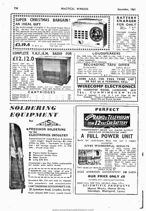
LOUDSPEAKERS 5in., 1416, 61in., 16/ -, 8ín., 16/6, 6 x 4ín., 14/6, 7 x 4in., 15/ -, 8 x 5in., 23/ -, 10in., 30/ -, 10 x 6in., 25/ -, 12m., 32/6. All above 3 ohms impedance. P. & P. 2/6. 12ín. 15 ohms. Hi -Fi Celestion £4.19.6.
RECORDING TAPE OFFER STANDARD LONG PLAY
600ft. on 5in. spool 151- 90011. on Sin. spool 18/6 85011. on 5 in. spool 16/6 120011. on 51in. spool 21/-
1200ft. on Tin. spool 21/- 180011. on 7ín. spool 32/6 P. & P. 1/,
I SEND S.A.E. FOR FREE PRICE LIST I OR PAY US A PERSONAL CALL
758 PRACTICAL WIRELESS December, 1961
*************** * * * * * * * * * * * * * * ** * * * * * * * * * * * * * ** *SUPER CHRISTMAS BARGAIN! ....,...f1---- .1 * * **AN IDEAL GIFT moi; * * The WIRECOMP "JUNIOR 5" Transistor Pocket Radio * * Kit. An easy "first step" set for the young constructor. * *This miniature marvel with the BIG performance covers *medium and long wavebands -has an internal Ferrite rod II! D! -' * * aerial -5 transistors and 1 diode -200 milliwatt push pull *output -2 }in. speaker. Supplied in 41 x 31 x thin. * unbreakable plastic case with carrying handle. Complete * with full instructions. All parts sold separately. * Pf2 19 6 Circuit diagram 1/6,
P. & P. 2/ -. free with kit.
* * *************** * ** * * * * * * * * * * * * * * * * *** * * * * ** * **
BATTERY CHARGER FOR ONLY
2I/- P. &P. 3/ -.
Overnight charging ensures instant winter starting. Size 6 x 3 x 3tn. to grey metal case. 6 and 12 volts charging at 2 amps. A.C. Mains 200- 250 v. Complete with battery clips.
COMPLETE V.H.F. /A.M. RADIO FOR
>EI2.¡2.0 Brand new set, in superb walnut cabinet (size 19 x 8¢ x 14in. high). Covering 80- 100 Mc /s. 16-49 M., 200 -500 M. and 1,200 - 2.000 M. Mains trans. 200- 250 v. with 3 tap- pings. Ferrite rod aerials for A.M. Con- trols: volume on /off tone, tuning, w /change, gram, and ext. speaker position provided. Fully guaranteed. Post and packing 5/- extra.
CARTRIDGES Collaro Studio O Collaro Studio P .. ..
f
18/- 18/- 18/-
WIRECOMP ELECTRONICS 378 HARROW ROAD, LONDON, W.9 T E L : C U N N I N G H A M 9530 Hours of business: 9 a.m, to 6 p.m. Open all day
Saturday. Opposite Paddington General Hospital. Buses 18B and 36 pass the door.
SOLDERING EQUIPMENT
liV PRECISION SOLDERING for the ELECTRONICS INDUSTRY Comprehensive range -Robust & Reliable - Light weight - Rapid heating - Bit sizes 3/32in. to 3 /8in. - 'Permabit' or Copper bits - All voltage ranges 6/7v. to 230/ 250v. - Prices from 19/6.
Also Plastic Cable Strippers Miniature Solder Pots Heat Guards Long Life Bits
Illustrated is the 2Sw. 3 /16ín. replaceable bit model with safety shield.
I ADAMIN -the new range of pre -1 cision micro -soldering instruments- I
Have you had details'
Brochure No. SIO sent free on request. Sole proprietors and manufacturers: LIGHT SOLDERING DEVELOPMENTS LTD. 28 Sydenham Road, Croydon, Surrey
Phone: CROydon 8589 Grams: Litesold Croydon
PERFECT
fR4DlO TELEV,g,oN faoMlwoir CAR BATTERY
INDEPENDENT 200/240 Volt MAINS SUPPLY AMERICAN DYNAMOTOR UNIT
A FULL POWER UNIT Built for continuous duty not just a rotary
converter. GIVES WONDERFUL RESULTS
Input 12 volts, output 200/ 240 volts at 100 to 130 watts and 180 watts. Runs RADIOS, TELEVISIONS, Mains Lighting, ELECTRIC DRILLS and thou- sands of Appliances. Runs anything 200 /250 volts universal AC /DC. Built for heavy con- tinuous duty. Will last lifetime. Brand new condition.
Fully tested and ready for immediate use. SIMPLY PLUG IN
COST AMERICAN GOVERNMENT f40 EACH
OUR PRICE ONLY £8 including carr., packing and insurance.
SEND S.A.E. FOR FULL DETAILS: (Dept. LP)- SCIENTIFIC PRODUCTS Manor Works, Manor Drive, Cleveleys, Blackpool, Lancs.
rIC, _y S r-
www.americanradiohistory.com

December, 1961 PRACTICAL WIRELESS
B. & B. TELEVISION Cherrywh0000d 3955.
131 & 13Ia KINGSTON ROAD,
SOUTH WIMBLEDON, LONDON S.W.19
FOR THE FINEST, FASTEST SERVICE IN THE COUN'T'RY. We
probt mks you from
e Call r Phone, wenarre always pleased to help.
NEW! SEND FOR OUR COMPREHENSIVE L.O.P.T. SCAN COIL L.B.O., F.B.U., F.O.P.T. LIST
Invaluable a nearly
srvice makes
The and models,
evler compiled. Special quotations for the trade.
1 ItANSISTOIts Genuine
1. (D Dullard 2, OC81 OC R's imatched s
of pair. Including OMB. Diode.
for ONLY 22.2.6. Genuine
GET 14 Transistors
. E114'e Sets of
pair; D plus 1, GEX34 for ONLY £1.18.6.
SINGLE TRANSISTORS PRICE LIST Mallard: 0044, 10/ -: OC45. 9 / -; OLIO. 6/ -: 0071. 61 -; 0072, 71-:
0076, 7/ -: OCIO. 7/ -: 0081 7I-; OC81D. 6 / -. G.E.C.: G va ;s a1ee Aailble
In matched pairs t1%- xtra- Dulard Diodes: OÁ70, 2/9; 0A79, 2/9; 0A81. 2/9; 0A91, 3/6; G.E.C.: GEX34. 3/3.
All above are genuine manufacturers new 1st grade.
SURPLUS TRANSISTORS Red Spot. A F. 0071 and 72. Equivalent . .. .. 4/3 each White Spot, R F. 0C44 and 45. Equivalent :: 5/-
- each Diodes, general purpose Various other types to stock. Please ask for prices of types not listed.
TURRET TUNERS. Various Makes: 10, 16. 38 Mc /s, 40 /-.
EXAMPLE OF TRANSFORMER LIST L.O.T. SCAN COILS
FERGUSON: (New) (Used) (New) (Used). 103T, 105T .. .. .. 69/9 35/- 601- 35/- 992/4/6/8 .. .. 69/9 35/- 60 /- 35/-
(New) (Used) (New) (Used)
PV4:VT4. V7 .. .. 52/6 35/- 55 /- 35/- VT7. CTM4.. 52/6 851- 55 /- 35/-
MURPHY: (New) (Used) (Used only) V214. V240. V250 .. .. 60 /6 35/-
- EKCO: (New) (Used) (New) (Used) 221.283 .. .. .. 47/3 30 /- 40/- 27/8 231. 284. 293.. .. .. 54/- 35 /- 40/6 27/6
REGUNNED CATHODE RAY TUBES all with 12 -month Guarantee
ALL MAKES: 121n.. 23.15.0; 14111.. 24.5.0; 17in., 24.15.0. ADD: 10s. for 90° tubes; 15 /- for 110° tubes; 5/- for Electro- static types. SECONDS, with 12 -month Guarantee -ALL MAKES: 121n..
22.15.0; 141n.. 23.5.0 (when available): 171n.. 23.15.0. SECONDS, No Guarantee -ALL MAKES: 121n.. 21.5.0; 14in.,
21.15.0 (when available); 17111., £2.15.0. NOT
allowance on old tube GUARANTEE
if in good condition. S.
. . THE FABULOUS R.T.D. TRANSISTOR SIX LATEST ON THE KIT MARKET
Spec.: Six transistor plus diode, printed circuit. superhet, ferrite rod aerial. Automatic gain control to stop overloading. Output 450mW in push pull. All components brand new and guaranteed. Neat, small, two-tone grey cabinet. Two radios in one, portable and car radio. Incorporates car aerial input socket.
I Everything to build this superb Transistor Radio. Only £8.9.8.
VALVES -GUARANTEED 90 DAYS AZ31
big EF390 61- P01.83 11/3 U30 8/8 8P61 2/3 101:1 3018
D77 8/- EF50 8/9 PC184 918 U52 7/- W77 5/- 100.2 18/.
D577 4/6 EF80 4/6 PL33 8/8 U191 91- 577 8/- 101.13 9/-
DK91 619 EF91 31- PL36 10/9 11281 9/- 504 5/- 101.14 9/. DE92 8/. EF92 5/- PL38 14/8 0282 201- 5V4 91- 12ÁT7 6/6
1)1(91 7/6 EL33 6/8 PL81 8/8 U301 20 /- 5Y8 10/0 12AU7 5/9
DL92 6/9 EL38 14/8 P1.02 819 13801 22/6 5Z4 101- 20D1 8/6
01.94 8/9 ELs4 7/- FL83 71- UAF42 8/- GALS 31- 2092 9/- 6A416 3/- 20L1 12/8
Eß91 3I- EY51 E
719 PY32 10 /- UC542 7/9 8CÚ8 27/8 201.1 1018
EBc33 61- EY86 7/6 PY00 8/6 11941 8/8 (04 3/- 201,3 12/-
RUM 9/8 EZ40 8/- PY81 81- 0942 3/9 691 5/- 201.4 10 /8
ECC81 6/3 KT33C 61- FY82 8/8 UL41 7/3 6F12 8!- 2750 14/- ECC82 5/9 KT36 8/8 P230 10 /- UL48 7/3 6F13 7/- 3001 7/- ECC84 8/- KT66 15/- U22 9/8 01.44 11/8 8914 9/8 30L1 7/- E0980 8/- FCC84 7/- U'24 10 /- UY41 6/8 6E15 9/6
30P4 10 /9 Eel35 91- P0089 8/8 125 121- U08 14 /6 61.1 12/6
20581 8/- PCF80 7/- U28 12/- UU9 8/8 8V6 6/- 185BT 14 /-
These are only examples of our valves: if you do not see what you
require send stamped addressed envelope for special quotation.
We pride ourselves that we can obtain and supply any TV spare OUR GIGANTIC STOCKS INCLUDE: Line Output, Frame Output.
any Sound
model Television. Mocking.
leasená kOus for ANY and
components you require, we are almost certain to have them.
TERMS: S.A.E. all enquiries. C.W.O. or C.O.D. 3/- extra. Postage on Valves, 6d. each. C.R.T.s 12/6 inc. insura
ICnce. SATISFACTION ASSURED. RETURN POST SER E.
l
759
IN THE HOME, IN THE CAR,
BY THE SEA, IN FIELDS AFAR
THE CONTESSA IS VOTED BEST OF ALL
A really remarkable
2 BAND 6 TRANSISTOR
SUPERHET KIT (As displayed at the Radio Hobbies Exhibition)
The CONTESSA is the professional looking set with the professional performance.
Study these brilliant features which cannot be found in any other kit ....
Waveband Coverage of 530 k /cs to 1620 k /cs and 160 k /cs to 270 k /cs. Assured reception of at least a dozen stations in daylight! Large clearly -calibrated station -named dial. internal high -gain Ferrox Aerial. 5.1 ratio slow motion tuning. Fitted with the latest 12000 line high -flux loudspeaker. Power of 410 milliwatts from the single -ended push pull final stage. Specially designed aerial matching coil for use in a CAR. Only first grade fully guaranteed Mazda matched transistors and diodes are used. Double tuned IF transformers for maximum gain and knife -edged selectivity. Fully drilled printed circuit panel marked with component numbers. The two colour case measures 10 x 7} x 3}in- and weighs approx. 4 lbs. Battery lasts 4 months with normal usage. Book supplied with detailed assembly ins- tructions, diagrams and circuitry. Anyone can build this set -everything supplied just a soldering iron required.
Inclusive price for all associated components, 0
n't cabinet and battery. complete in every detail. LL
Plus 3/6 Regd. P.P. Or our BUY AS YOU BUILD SCHEME any parts sold separately. Send for comprehensive descriptive manual and parts list, 3/6 post free.
See and hear a working model at:- RADIO CLEARANCE LTD.
27 Tottenham Court Road, London W.I Telephone: Museum 9188
www.americanradiohistory.com
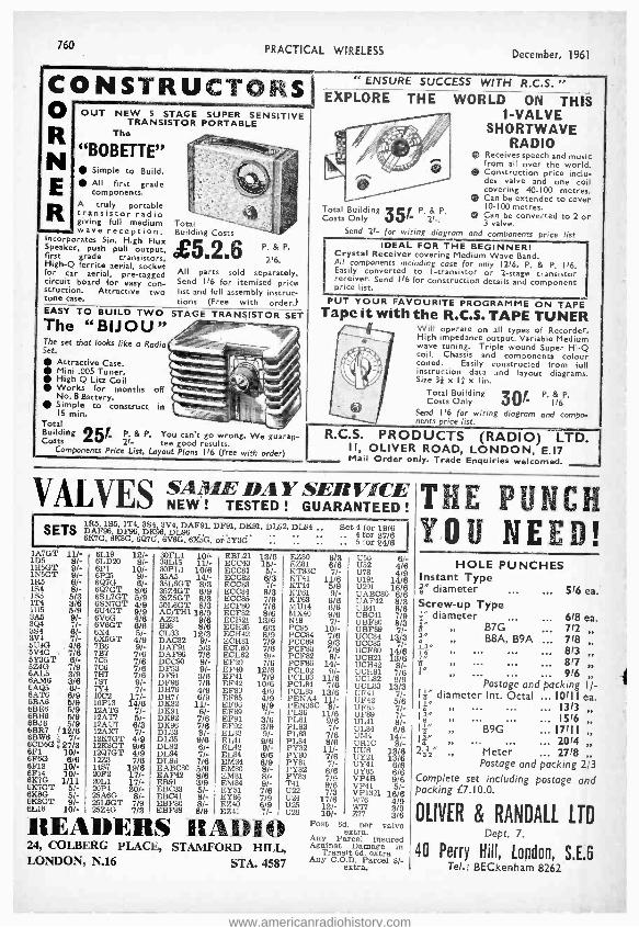
760 PRACTICAL WIRELESS
CONSTRUCTORS O
N d /1
E .
OUT NEW 5 STAGE SUPER SENSITIVE TRANSISTOR PORTABLE
The
"BOBETTE" Simple to Build. All first grade components.
A truly portable transistor radio giving full medium Total wave reception. Building Costs
Speaker, Sin.
pull High Flux /
Speak push pull output, QiF /i first grade transistors, 2/6. High -Q ferrite aerial, socket for car aerial, pre- tagged All paru sold separately. circuit board for easy con- Send 116 for itemised price struction. Attractive two list and full assembly instruc- tone case. tions (Free with order.) EASY TO BUILD TWO STAGE TRANSISTOR SET The "BIJOU" The set that looks like a Radio Set.
Attractive Case. Mini .005 Tuner. High Q Litz Coil Works for months off No. 8 Battery. Simple to construct in IS min.
Total Building 25P P. & P. You can't go wrong. We guaran- Costs 2/- tee good results.
Components Price List, Layout Plans 116 (free with order)
P. & P.
December, 1961
" ENSURE SUCCESS WITH R.C.S. " EXPLORE THE WORLD ON THIS
1 -VALVE SHORTWAVE
RADIO Receives speech and music from all over the world. Construction price inclu- des valve and one coil covering 40 -100 metres. Can be extended to cover
P. Total Building 10 -100 metres. Costs Only 35 P. g,
2l -. vn be converted to 2 or 3 valve.
Send 21- for wiring diagram and components price list IDEAL FOR THE BEGINNER!
Crystal Receiver covering Medium Wave Band. All components including case for only 12/6. P. & P. I 16. Easily converted to I- transistor or 2 -stage transistor receiver. Send I/6 for construction details and component price list.
PUT YOUR FAVOURITE PROGRAMME ON TAPE Tape it with the R.C.S. TAPE TUNER
Will operate on all types of Recorder. High impedance output. Variable Medium wave tuning. Triple wound Super Hi -Q coil. Chassis and components colour coded. Easily constructed from full instruction data and layout diagrams. Size 31 x If x lin.
Total Building & Costs Only 30 p, p,
I/6 Send 116 for wiring diagram and compo- nents price list.
R.C.S. PRODUCTS (RADIO) LT II, OLIVER ROAD, LONDON, E.I7 Mail Order only. Trade Enquiries welcomed.
VALVES
SAnIF. Di } SERVICE NEW ! TESTED ! GUARANTEED !
I SET S 1R5, 185, 1T4, 3S4, 3V4, DAF91, DF91, DK91, DL92, DL94 DAF96, DF96, DK96, DL96 6K7G, 6K8G, 6Q7G, 6V6G. 6105G, or 5Y3G
Set 4 for 19/8 .. 4 for 27/6 .. 5 for 24/6
IlA7GT 11/-
1DH6GT 9%- ï RSGT 8Ì- 154 8/-
1Ú6 5 3 éi-
6V 7%8 6Y3GT 8/- fiZ4G 7/9 8AL5 3/9 8AM8 3/8 6AQ5 6/-
138
6/9
5¡9 613116 5/9 BBJ6 5/9 6BR7 /12/6 BCDw88(3 e 27%3 8F1 10/- 6F6G 6/8 6F13 10/- 6F14 10/- DOG 1/11 6K7GT 5/- 6K8G 5/- 6K8GT 9/- 8L1B 10/-
8L19 12/- 30FL1 10/- EBL21 13/6 EZ80 6/3 U50 8/. 6LD20 8/- 30L15 11/- ECC40 15/- EZ81 6/6 U52 4/6 6P1 10/- 30PL1 10/8 ECC81 5/- KT33C 7/- U78 4/9 6P25 9/- 35A5 14/- ECC82 8/3 KT41 11/8 U191 14/6 6Q7G 6/- 35L6GT 8/3 ECC83 7/- KT44 5/9 U291 16/6 6Q7GT 8/8 35Z4GT 6/9 ECC84 8/3 KT61 9/- UABC80 8/8 6SL7GT 5/9 35Z5GT 8/3 ECC85 7/9 KT63 6/6 UAF42 8/3 6SN7GT 4/9 50L6GT 8/3 ECF80 7/6 MU14 6/6 U1341 8/6 6U4GT 9/9 AC/TH118/9 ECF82 8/6 MX40 9/6 UBC41 7/9 4/6 AZ31 9/6 ECH21 13/8 NI8 7/- UBF80 8/3 6VT 6/6 B38 8/6 ECH35 6/3 PC95 10/- UBF89 7/- 6X4 5/- CL33 12/3 ECH42 8/9 PCC84 7/8 UCC84 13/3 6X5GT 4/9 DAC32 9/- ECH81 7/9 PCC89 9/3 UCC85 7/- 9/- DAF91 5/3 ECL80 7/6 PCF80 7/9 UCF80 / 7B7 7/8 DAF96 7/8 ECL82 9/- PCF82 8/- UCH21 1314/6
8 7C5 '7/6 DCC90 9/- EF39 7/8 PCF86 14/- UCH42 8/- 706 7/8 DF33 9/- EF40 12/6 PCL82 9/- UCH81 7/6 7H7 7/6 DF91 3/6 EF41 7/9 PCL83 11/6 UCL82 9/9 7S7 9/- DF96 7/6 EF42 10/6 PCL84 7/6 UCL83 13/3 7Y4 7/- DH76 4/9 EF80 4/9 PCL85 13/6 UF41 7/- 10C2 17/- DH77 6/9 EF85 4/9 PENA4 11/- 13F42 5/8 1OP13 14/6 D832 11/- EF86 9/9 PEN36C 8/- UF85 7/. 12AT8 7/- DK91 6/- EF89 7/- PL36 11/6 UF89 7/- 12A77 5/- DK92 7/8 EF91 3/6 PL81 9/6 UL41 8/- 12AU7 6/3 DK96 7/8 EF92 3/9 PL82 7/- UL84 6/6 12AX7 7/- DL33 8/- EL33 9/- PL83 7/6 UM4 12K7GT 4/9 DL35 9/8 EL41 9/8 PL84 8/6 UR1C 18//- 12K8GT 9/8 DL92 6/- EL42 9/- PY32 11/- UU6 13/6 12Q7GT 4/9 DL94 7/- EL84 6/6 PY80 7/6 UY21 13/8 12Z3 7/6 DL96 7/6 EM34 8/9 PY81 7/- UY41 8/8 1487 19/8 EABC80 5/8 EM80 8/- PY82 8/6 UY85
9/6 6/6 20F2 17/- EAF42 8/6 EM81 8/- PY83 7/9 VP4B 20L1 17/- EB91 3/9 EM84 9/- T41 9/8 VP41 5/- 20P4 20/- E13C33 5/- EY51 7/8 U22 7/3 VP1321 16/6 25A60, 8/- EBC41 8/- EY86 7/9 U24 17/6 W76 4/9 25L8GT 7/9
FBF89 8/9 EZ 6/9 Ú 12/-
/- W77
3/8 READERS RADIO Post 13c1xt izr valve Any Parcel insured
24, COLBERG PLACE, STAMFORD HILL, AgTransitD6dmextia in
LONDON, N.16 STA. 4587 eztra. Any C.
extra. Parcel 3/-
THE PUNCH YOU NEED!
HOLE PUNCHES Instant Type r diameter ... ... 5/6 ea. Screw -up Type f" diameter , 6/8 ea. 8" PP B7G .., 7/2 r B8A, B9A ... 718
PP
i "" OP ... - -- 817 DO .,. . 9/6 .,
Postage and packing I f- f" diameter Int. Octal ... 10/11 ea.
3" â"
á "
2"
PP
PP
B9G ... 17/11
Meter .. 2718 Postage and packing 2/3
Complete set including postage and packing £7.10.0.
OLIVER & RANDALL LTD Dept. 7.
40 Perry Hill, London, S.E.6 Tel.: BECkenham 8262
www.americanradiohistory.com

December, 1961 PRACTICAL WIRELESS
ERSIN MULTICORE SOLDERS
for a first class joint every time
Ersin Multicore contains 5
cores ofextra- active, non- corro- sive Ersin Flux. Prevents oxida- tion and cleans surface oxides.
SIZE 1 CARTON
5/- HANDYMAN'S
CARTON
Suitable for 200 6`d. average joints.
Wherever precision soldering is essential, manufacturers, engineers and handymen rely On MULTICORE. There's a
MULTICORE SOLDER just made for the job you have in hand. Here are some of them.
NOME CONSTRUCTORS 2/6 PACK
In addition to the well -known Home Constructors Pack (con- taining 16ft. of 18 s.w.g. 60/40 alloys) a similar pack is now avail- able containing 35ft. of 22 s.w.g. 60/40 alloy especially suitable for printed circuits.
SAVBIT TYPE 1 ALLOY A specially formula- ted alloy to reduce the wear of soldering iron bits. Contains 5
cores of non- corro- sive Ersin Flux and is ideal for all sol- dering purposes. SIZE 1 CARTON 5/- Available in three specifications.
BIB WIRE STRIPPER
AND CUTTER
Strips insulation without nicking wire, cuts wire cleanly. splits extruding nex.,5 /6 each F
MULTICORE SOLDERS LTD.,
MULTICORE WORKS, HEMEL HEMPSTEAD, HERTS. (BOXMOOR38111)
"There is no Virtue without Courage -
No Reward without Labour"
Not simply a school motto but at B.N.R.S. a creed and a way of life. We owe to it all we have and are. If you are prepared to make it your motto and live up to it, we can
help you to get to the top. It will take time, it will take effort, it will take courage, and on top of all this you will actually be charged fees.
If we haven't succeeded in putting you off, write for details, today, to:
Mr. J. SYKES (M.I.E.E., M. Brit. I.R.E., M.I.N.)
Principal :
BRITISH NATIONAL RADIO SCHOOL Red Lion Court, Stalbridge, Dorset
Britain's premier Radio Correspondence School specialising in City and Guilds examinations.
informative, amusing
and human
761
ANEW BOOK By G. A. BRIGGS AND 64 COLLABORATORS Publication Date 15th November 1961
Not a "Who's Who" in Audio but reminiscences by the Editor, G. A. Briggs, and many of the interesting people he has met during some thirty years of audio activities. There are entertaining glimpses of recording studios with world- famous soloists; of triumphs and failures with prototype speakers, pick- ups and amplifiers. Truly a
book that brings to life the heart of Audio being -as the B.B.C. critics would say - evocative, and, as the Editor ventures to say -informative and amusing.
I 9/6 (2019 post paid)
344 pages with 112 photo- graphs and illustrations. Printed on fine quality art paper and cloth bound. Available through Book Shops and Radio Dealers. or in case
of difficulty direct from the Publishers.
WIRELESS WORKS LTD
IDLE BRADFORD Yorkshire
Tel.: Idle 1235/6 Grams: Wharfdel, Idle, Bradford.
www.americanradiohistory.com

762 PRACTICAL WIRELESS December, 1961
AVO METERS MODEL 7 £12.10.0. MODEL s £17.10.0. Guaranteed perfect Complete with leads and bat (cries. Registered post and Packing 5/- extra. fra TIMETERS. 10001) /volt. A.C. and L.C. volts, 0 -10, 50, 250 500 & 1000 D.C. current 0 -10. 100mA. Resistance 0-2kí2 and 0 -200K ii. Bakelite case. complete with test leads. BRAND NEV,' 59/6.
I.
BC 221. The most accurate precision portable heterodyne frequency meter 125Kc /s to 20ó1c /s. Complete with original individual calibration book. Guaranteed perfect £16. CItVSTAL CALIBRATOR No. lu. Good condition, tested, will nstruction manual. ONLY 59/6 or AS NEW with three spare valves eads. etc. £4.10.0. P. & P. 3/0.
Type PCR,C Has UÈeli-cont 1 ed1 speaker. Covers 850- 2000, 200-550 ND NEW CONDITION
USED (Good condition) £9.19.8 67.19.6 Type PCR -2, Requires external speaker. Covers 850 -2000. 200 -500 and 13-50 metres USED (Good condition)
Carriage (any type) 10/6. Full details S.A.E. Any model fitted with BRAND NEW INTERNAL POWER SUPPLY, guaranteed ready for use on A.C. mains £2 extra. Moving Coil Phones. Finest quality Canadian, with Chamois ear- muffs and leather -covered headband. With lead and jack plug. Noise excluding supremely comfortable, 10/6, post 1/6.
£8.19.6
GIANT COMPONENT PARCEL. Contains 100 ) and 1 watt resistors, 50 Hi Stab resistors, W/W resistors, carbon and W/W pots, 100 capacitors (mica, paper, Sprague bias. variable, etc.). valveholders, tag strips, metal rectifiers, sleeving, etc. All com- ponents are unused. GUARANTEED VALUE, 25/ -, plus 2/6 post. T RANSISTOR SETS
We now stock The Pocket 4, a neat little lob which can be made for Companion (Printed Circuit
equal to the Version
b best). Easily constructed for only £9.19.6. Gladly demonstrated to callers.
CHARLES BRITAIN (RADIO) LTD. II Upper Saint Martins Lane, London, W.C.2 TEMple Bar 0545 Shop Hours 0-6 p.m, (9-1 p.m. Thursday)
Open all day Saturday,
SOUTHERN RADIO'S WIRELESS BARGAINS PORTABLE TEST METERS. (As featured in March issue, pages 1005 to 1010) 0 -1000 ohms; 0 -60 mA; 0 -15 v., 0 -3 v., 12/6 each. TRANSMITTER RECEIVERS. "Type 38" with 5 valves. New but untested. No guarantee, 25,- each. Post paid. ATTACHMENTS FOR "38" TRANSMITTER -RECEIVER; Headphones 15/6; Throat Microphones, 4/6; Junction Boxes, 2/6; Aerials, No. I, 2/9, No. 2, S /3; Webbing, 40-; Haversacks, 5/6; Valves- A.R.P.I2 4/6. A.T.P.4, 3/6. Set of five valves, 19, -. Postage on each (tern 1/6 extra (except valves). ATTACHMENTS FOR "18" TRANSRECEIVER. Head- phones, 15/6; Microphone 4a, 12/6; Aerials, 5, -; Morse Key, 6,6; Valves- A.R.P.12, 4/6, A.T.P.4, 3/6, A.R.8,7/6; Set of six valves, 25,-, Official booklet "18" T -R Circuits, etc., 6,6 post paid. Postage extra (except valves) I '6 each item. QUARTZ CRYSTALS. Types F.T.241/F,T.243 2 pin +in. spacing. F.T.241 20 to 38.9 Mc /s (54th and 72nd Harmonic). F.T.243 5700 to 8650 kc /s (Fundamental), 4/6 each. Lists of available frequencies on request. Crystal Holders for F.T.241/243, I/3. F.T.241/243 Crystals. New but not guaranteed (ideal for using the case or regrinding). 12,6 per dozen. Post paid. RECORDING BLANKS. New 13ín., 6,- each or 15 complete in Tin, E4.
BOMBSIGHT COMPUTERS. Ex-R.A.F. Wealth of gears. motors, blowers, etc. Ideal for experimenters, L3.12.6, Carr. paid. RESISTANCES, 100 Asstd. Useful values, new. 12,6 per 100. CONDENSERS. 100 Ass. Mica Elec., Tub., etc. New 15,- per 100. MORSE PRACTICE SETS. Key with Buzzer on Base, with battery. 12/6, postage 2, -. LUFBRA HOLE CUTTERS, Adjustable. (in- to 3 }in., 713, STAR IDENTIFIERS,
I -AN. Covers both hemispheres, 5/6. VISUAL INDICATORS (IOQ4). Type 3 with 2 meter move- ments, 2 neons. New 12, -. MAGNETS. Strong Bar, tin. x tin. I/6 each. COMMAND RECEIVERS B.C. 454 3-6 Mc /s. B.C. 455 6-9 Mc /s. Complete with 6 valves, 47/6 each. POST OR CARRIAGE EXTRA, FULL LIST OF RADIO BOOKS, ETC., 3d.
SOUTHERN RADIO SUPPLY LTD. II LITTLE NEWPORT ST., LONDON W.C.2. GER. 6653
FIRST -CLASS RADIO COURSES .. .
GET A CERTIFICATE! QUALIFY AT HOME -IN SPARE
TIME After brief, intensely interesting study -undertaken at home in your spare time -YOU can secure your pro- fessional qualification or learn Servicing and Theory. Let us show you how. I FREE GUIDE
The New Free Guide contains 132 pages of information of the greatest I importance to those seeking such I success -compelling qualifications as A,M.Brit.I.R.E City and Guilds 1 Final Radio, P.M.G. Radio Amateurs' Exams Gen. Cert. 1 of Educ. London B.Sc. (Eng.),
1 A.M.I,P,E, A.M.I.Mech.E Draughtsmanship (all branches) I etc., together with particulars of
our remarkable Guarantee of SUCCESS OR NO FEE I Write now for your copy of this invaluable publication. It may well prove to be the turning point in your
career FOUNDED 1885 -OVER I
L _ I50,000 SUCCESSES. - d NATIONAL INSTITUTE OF
ENGINEERING (Dept.461), 148 HOLBORN
LONDON, E.C.I S. Africa: P.O. Box 8417, Jo'burg. Australia: P.O. Box 4570, Melbourne.
Just Published RADIO
CONTROL MANUAL by E. L. Safford : r. ' 25, -. . Postage 9d. ' TRANSISTORS -HOW TO TEST
THEM. Gernsback Lib, I6í -. Postage 8d. ' HANDBOOK FOR RADIO OPERATORS, G.P.O. 6/ -. Postage I,
REFERENCE MANUAL OF TRANSISTOR CIRCUITS. ' Mullard. 12/6. Postage It -.
RECORDS AND GRAMOPHONE EQUIPMENT, by E. N. Bradley. ' 8,6. Postage 6d. ' TELECOMMUNICATIONS, W. T. Perkins. 21, -. Postage 9d. ' THE SUPERHETERODYNE ' RECEIVER. A. T. Witts. 20, -, Postage 6d. ' VALVE & TELETUBE MANUAL
L. No, 9. Brimar. 6, -. Postage I, -.
110.
RADIO VALVE DATA, Compiled by "WW" 7th Ed. 6, -. Postage 1Od.
COMPLETE CATALOGUE I / -.
THE MODERN BOOK CO. BRITAIN'S LARGEST STOCKISTS ' of British and American Technical Books
19 -21 PRAED STREET ' LONDON, W.2 Phone: PADdington 4185 Open 6 days 9-6 p.m.
SHORT-WAVE H.A.C. EQUIPMENT AND
SHORT -WAVE KITS Famous for over 25 years for ... S.W. Receivers and Kits 01 Quality. ILA -C- were the original suppliers of SHORT -WAVE RECEIVER KITS for the amateur constructor. Over 10,000 satisfied customers -Including Tech- nical Colleges, Hospitals, Public Schools, Hams, etc.
Improved designs with Denso coils: One-valve Two -valve Kit,
Model Model "E ", Price 50/-. New Addition: Model "K ". Super sensitive "All Dry" Receiver, Special inc. price. Complete Kit, 77/ -.
All kits complete with all components, accessories and full Instructions. Before ordering call and inspect a demonstration receiver, or send for descriptive catalogue and order form.
POST THIS COUPON NOW "H.A,C." SHORT -WAVE PRODUCTS
(Dept. TL), 44 Old Bond Street, I London W.1 Please send me FREE and without obligation your 1961 literature. NAME I
ADDRESS I
I 411.11 MEP MN MEN BIM s,.111M
www.americanradiohistory.com

December, 1961 PRACTICAL WIRELESS
FIVE -TRANSISTOR POCKET RADIO
COMPLETELY PORTABLE, NO AERIAL OR EARTH REQUIRED
* Size 41x3}xIin.
* Output 200m/W
* S First quality transistors
* Push -pull output
* Fitted 2 +in. high -flux moving coil speaker
* Medium and long wave * Internal high gain ferrox aerial * Twin coloured case in red and black * All parts available separately * Circuit- diagram 116. Free with kit.
I PRICE NLY E2f19f6
plus 3'6 post and packing
RADIO & TV LTD. (Dept. 5T) 23 High Street, Acton, London, W.3.
EXPRESS ELECTRONICS ROSEDENE LABORATORIES
KINGSWOOD WAY, SELSDON, SURREY TEED
VALVES NEW FOR HREEDMONS
1C7 -/8 68A8 61- 8DA 4/- DF96 8/- LF41 9/- PCL84 7/-
1C3 8/- 612E6 '/- 12A118 10/- DH76 7/6 1.F'7O 8/- PLe1 12/6
1F1 81- BE116 5/912AT7 8/- 1.1177 6/- 1.F86 9/- PL82 7/-
1F3 7/6 68.16 5/9 19A117 5/6 1)11142 8/6 61,91 41- PL. 7 7/6
IF DI 8/. 111107 8/912A57 6/-111115010/-kF99 516 1'181 617
1F09 7/60887 10/612BE6 81t 1/9621 7/6 h141 9/8 P182 7/8
1L4 8/968W6 '/61281(7 10/911K9'9 7/6 h L84 7/- I'183 7/C
1P1 8/- 615627 7/- 12168CT11,- 1.698 8/- h6184 101- 1419 11/6
11.1.0 7/661.10 9/- 190711T 7/6 D1.92 '/616185 10/- 1126 9/6
1P11 7/6 61/1 4/- 16A8 9/- DI.94 6/6 1 Y51 7/6 U52 7/6
11L5 6/- iiN12 4/. 25A60 8/6 UL96 8/- F Y81 101- 1.176 7/6
185 8/- 61160T 2/- 251,6GT 7/6 E1291 41- Z40 7/6 U78 51-
1T4 7/6 6J70T 7/8 25'/.4(1 9/- EEC41 10/- E'L80 6/- UR041 8/6
1125 510 69670 5/6 30C1 6/9 E13180 8/6 Fffi81 8/9 UCH42 9/6
304 8/- 69680 61- 30L1 7/- E1.ti81 61- 96'l'33C el- UF41 816
884 718 6070 5/6 35L60T 9/- 961)6782 5/6 16.166 11/6 U L41 8/6
314 6/6 68L7oT 81- 35W4 8/6 E(7(:83 6/- N17 7/6 UY41 7/6
51140 7/8 689670T 6/- 35240T 8/- ECC84 716 3.18 8/- W76 616
5130T 5/- 896(1 7/853KU 1018 EC1/80 816 619 7/6 W142 8/6
3240 9/8 6\4 5/. 3763 7/6 ECF82 8/- 5709 /- 517 7/6
6A966 6/e 6150 5/- 80 b/- 6671142 91- P06784 6/9 5142 9/-
8AL5 4/- 6SSOT 6/- DAF91 7/6 F:C1181 10/- PUF80 6/9 1150 9/-
6A6t6 41- 787 7l6 DAF98 81- ECL80 8/8 l'CF82 7/- 277 41-
OATS 81- 787 9/6 DF91 7/6 EC1.82 9/- PI:LB'l 8/- Z1117 716
High Stability Realflora 4W 6°/, 50 O to 1M, 9d. Midget Ceram ea 300 v. 9d.
Coax. Super 860v. 300 MA lin` a }in. 17/6. Coo r. Cooled É ÓeeL50 MA 6/6 0085 IdA 816.ta
VOLUME CON'T'ROLS MIDGET SIZE LONO SPINDLES. D. P.
4/ -. Lees ewiwh, 1/6. Values 10K to 2M, BOA. 1370 v. holders 9d., Screena
Dd.
VALVES MATCHED IN PAIRS EL64 17/, N709 17/ -, 6160 111 -, 6883, 10 /- Ve) Van. lw'Á l'on O.P. Trans/re-mere /or above 3 -15 O 14/6, I'. & 1'. 1 /6. 121r.. P.M. Strakere 3,0 94/8. Baker's 'Relfluret" 22in. 15 0 .5W, 901 -. 1216. Stereo Model,
87.7.0. SETS OF VALVES
ÚK91, DF91, DAF91, ÚL92 or DL941. .1916 ECH42, EF41, EBC41, 1/1196, DF96, DAF96, DL96 28/6 EL4l, E240 87/6
103, 111, 111)1, 1P3 97/6 UCH42, UF41, UBC41, 1R5, 1T4, 185, 384, or 3V4 19/6 111.41, UY41 85 /-
Poetage and packing Od. Over £1 poet free. C.O.D. 2 /6.
763
an absolute practical minimum
of `\
WOW and
That has been one of our main objectives since we started making tape decks and recorders and we tee/ that we hale achieved this (along with many other notable features) in our present range of recorders. By the
use of high quality components and fastidious precision assembly these "wow and flutter" figures are maintained:-
Below .05;i6 at IS i.p.s. I Below .15% at 3 at n i.p.s.
Below .1% at 74 i.p.s. I Below .25% at I¡ i.p.s.
The Brenell Mark 5 deck at 28 gns. has greater precision and dependability than you are ever likely to find elsewhere at any-
where near the price.
17'S A HEART THAT IS AS SOUND AS SOUND CAN 18E
J
Abridged Specification 3 INDEPENDENT MOTORS /Capstan motor -hysteresis synchronous) 4 RECORDING AND PLAYBACK SPEEDS I. 3L 7# and 15 ips. FAST REWIND (1,200ft .
rewound in either direction in 45 secs.) ACCEPTS 8 1in. reels PAUSE .CONT ROL. INTER- LOCKED CONTROLS. DIGITAL REV. COUNTER. PROVISION FOR EXTRA HEADS (Mono or Stereo/
MARK 5 DECK 28 Gns.
MARK 5
Type 'M' 88 Gns. TAPE RECORDERS:
MARK 5: 64 Ges. MARK 5 STEREO: L99.12.0. 3 STAR: 58 Gns.
3 STAR STEREO: 89 Gns.
Full details and the address of your nearest stockist from the sole
manufacturers:
BRENELL ENGINEERING CO. LTD.,
IA DOUGHTY STREET, LONDON, W.C.I.
Tel: Chancery 5809 Holborn 7358.
www.americanradiohistory.com
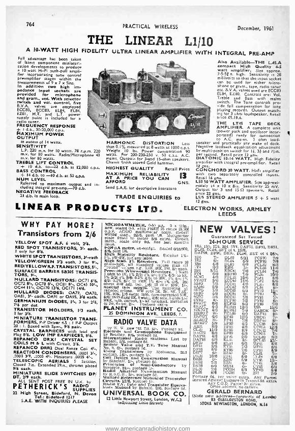
764 PRACTICAL WIRELESS December, 1961
THE LINEAR L1/10 A 10 -WATT HIGH FIDELITY ULTRA LINEAR AMPLIFIER WITH INTEGRAL PRE -AMP
Full advantage has been taken of latest component miniaturi- sation developments to produce a 10 -watt Hi -Fi push -pull ampli- fier incorporating tone control preamplifier stages within the measurements of 9 x 7 x Sins. In addition two high im- pedance input sockets are provided for microphone and gram., etc. With selector switch and vol. control, five B.V.A. valves are employed ECC83, ECC83, EL84, EL84, EZ81, H.T. and L.T. power supply point is included for a radio tuner. FREQUENCY RESPONSE
I d.b., 30- 20,000 c.p.s. MAXIMUM POWER OUTPUT
in excess of 14 watts. SENSITIVITY
L.P. 220 m.v. for 10 watts. 78 r.p.m. 220 m.v. for 10 watts. Radio /Microphone 40 m.v. for IO watts.
TREBLE LIFT CONTROL - 10 d.b. to -22 d.b. at 12,000 c.p.s. BASS CONTROL t 14 d.b. to -10 d.b. at 50 cps. HUM LEVEL
Referred to maximum output and in- cluding integral pre- amp. -70 d.b.
NEGATIVE FEEDBACK 21 d.b. in main loop.
HARMONIC DISTORTION Less than 0.1% measured at 8 watts at 1000 c.p.s. Weight 10 lbs. Power consumption 90 watts. For 200 -230 -250 v. 50 c.p.s. A.C. mains. Outputs for 3 -and 15-ohm speakers. Chassis finish stoved Gold hammer. HIGHEST QUALITY Retail Price MAXIMUM RELIABILITY 13 AT A PRICE YOU CAN AFFORD G NS. Send S.A.E. for descriptive literature
TRADE ENQUIRIES to
LINEAR PRODUCTS LTD.
Also Available -THE L.45.A compact High Quality 4-5 watt amplifier. Size approx. 7 -5 -Sein. high. Sensitivity is 28 millivolts so that the input socket can be used for either micro- phone or gram., tape, radio tuner etc. B.V.A. valves used are ECC83 EL84, EZ80. Controls are: Vol. Treble and Bass with mains switch. The Tone controls pro- vide full compensation for long playing records. Output match- ing for 3 ohm loudspeaker. Retail price E5.19.6.
THE LT45 TAPE DECK AMPLIFIER. A complete unit (power pack and oscillator incor- porated) ready for connection to A.C. mains. 3 ohm loud-
speaker and practically any make of deck. Negative feedback equalisation adjustment by multi -position switch for 1 {, 3j and 7 }in. per second. Retail price 12 gns. DIATONIC 10-14 WATT. High Fidelity amplifier with integral pre -amplifier. Retail 12 gns. CONCHORO 30 WATT. Hi -Fi amplifier with two separately controlled inputs. Retail 16 gns. L50 50 WATT AMPLIFIER. Size approxi- mately 14 x 10 x 8in. Sensitivity 25 mV. Output for 3 and 15 fl speakers. Retail price 22 gns. L5 /5 STEREO AMPLIFIER 5 t 5 watt I2 gns.
ELECTRON WORKS, ARMLEY LEEDS
WHY PAY MORE? Transistors from 2/6
YELLOW SPOT A.F. 6 volt, 2/6. RED SPOT TRANSISTORS, 3/- each. 3 only for 816. WHITE SPOT TRANSISTORS, 3 /-each YELLOW /GREEN 313 each, 3 for 9/ -. RED /YELLOW R.F.TRANSISTORS,5 / -. SURFACE BARRIER SB305 TRANSIS- TORS, 9/ -. MULLARD TRANSISTORS: OC71 6/6, 0072 8/ -, 0078 8/- OC61 8/- 0C45 to /-, 0C44 I I/- OC170 13/6, 0C171 1416. MULLARD DIODES: OA79, OA70, 0A81, 3/- each. 0A91 or 0A95, 3/6 each. GERMANIUM DIODES, II -, 3 for 216, 7/6 per doz. TRANSISTOR HOLDERS, 1/3 each, 3 for 3/6. MINIATURE TRANSISTOR TRANS- FORMERS, P -P Driver 4.5 1 P -P Output 20 : I. Boxed with Spec., 9/6 pair. CRYSTAL EARPIECES with lead and Plug 816. LOW IMP EARPIECES, 8/6. REPANCO DRXI CRYSTAL SET COILS M & L with Circuit, 216. REPANCO DRR2 Dual Range Coil 4/ -. REACTION CONDENSERS, .0001 31 -, .0003 3/9, .0005 4 / -. Miniature .0005 4/ -. TELESCOPIC AERIALS 5 Section. Closed 7in. Extended 29in., chrome placed 9/6 each. MINIATURE SLIDE SWITCHES DP/ DT, 21 each.
ALL SENT POST FREE IN U.K. by
PETHERICK'S SUPPLIES 22 High Street, Bideford, N. Devon
Tel.: Bideford 1217 S.A.E. WITH INQUIRIES PLEASE
new,Rsca ed Ó 3, with FREE FREE 25 range 8,ÓÖ o.p.v. AC /DC multimeter scale, circuit wiring dial:, 22/6, post 1/6. Multimeter scale fitted to meter 2/6 extra. Circuit lusts.. scale only 9d. See last months issue. 0-500 µA meter, ex- equipt. Scaled 0/15 /600, 8/6, post 1/6. High Stability Resistors. Surplus 1 %- 5 %. 0W -2W, list available. High Stab. 1% Resistors. Full range 10 ohms -10M, all standard values plus all "round" values, e.g., 2.5K, 80K, 9M. 2/- each. Precision Wlrewound Resistors. 1 Watt 1 ohm to 1K, 1% 2/9: 0% 3/ -: 0.2% 4/3: to 5K. 1% 3/3: 0% 3/6: 0.2% 419: to 20K, 1% 4/ -; 0% 4/3: 0.2% 6 / -: to 100K 1% 6/ -: 8% 6/6. 350 ohms 20W adj. tap, 1/6; 50 ohm 10W, 1/ -. Special this month. The following at reduced prices. WW pots 1K. 2K. 5K, 7.5K. 10K. 50K, 1/8 each; 30ín. cam -corrected 50K, 4/6: twin gang 5K, 8 watt, 4/6: min. 5 ohm 1/ -: 200K, min. carbon, 1/- all spindled. Switches 4p 2w. 6p 5w. 2/ -. Postaee extra. PLANET INSTRUMENT CO.
25 DOMINION AVE., LEEDS, 7.
RADIO VALVE DATA by W. W. new 7th Ed. 6/ -. Postage 9d. Records and Gramophone Equipment
by Bradley, 8/6, postage 8d. international Radio Stations List by Babani, 2/6, postage 6d. Brimer Valve and T.V. Tube Manual No. 9, 6/ -, postage 9d. Using Transistors by Slobbema, 2nd edition, 18/ -, postage 1 / -. Coil Design and Construction Manual by Sinclair, 5/ -, pbstage 6d. Principles of Semi- Conductors by Scroggie, 21/-, postage 1 / -. Radio Amateur Examination Manual by R.S.G.B., 5/ -, Postage 8d. Millard Reference Manual of Transistor Circuits, 12/8, postage 1/ -. Radio T.V. Tube and Transistor Equiva- lents Manual by Babani, 9/8, postage 9d.
UNIVERSAL BOOK CO. 12 Little Newport Street, London, W.C-2
(adjoining Lisle Street)
NEW VALVES ! Guaranteed Set Tested
24 -HOUR SERVICE lItS. 155. 1T4, 354, 3V4, DAF91, DF91, DK91, 01,92. DL94, SET of 4, 18/6. DAF96, DF96, DK96, DL96, SET of 4 26/.. IDs 7/- DL92 5/11 PCF80 7/9 1R5 6/- DL94 6/9 PCF82 7/6 155 4/6 DL96 6/9 PCL82 8/3 1T4 3/3 EB91 3/- PCL83 11/6 3S4 5/11 EBC41 7/6 PCL84 7/6 3V4 6/9 EBF80 7/9 PL36 10/9 5U4G 4/3 EBL21 12/6 PL81 8/6 5Y3GT 5/6 ECC40 14/6 PL82 6/8 5Z4G 7/3 ECC81 4/9 PL93 6/6 hAM6 2/9 ECC82 5/9 PL84 8/- 6K7G 1/9 ECCilïi 6/3 PY32 11 /- 6Q7G 5/6 ECCS5
8/- 6 p81 7/- 6V6G 4/- ECF80 7/3 PY82 6/- 6V6GT 6/6 ECF82 8/3 PY83 7/3 6X5GT 4/3 ECM! 12/6 U25 11 /6 12K7GT 4/3 ECH42 7/9 UABC80 8/- 12K8GT 9/- ECL80 8/9 UAF42 8/-
12Q7GT 4/6 EF40 12/3 UBC41 7/- 35L6GT 8/- EF41 7/6 UBF80 8/- 35Z4GT 5/9 EF80 4/3 UCC85 6/6 AZ31 8/9 EF85 4/8 UCH21 12/6 CL33 11/9 EF86 8/9 UCB42 7/6 DAC32 8/6 EF89 6/9 UCH81 7/- DAF91 4/8 EF91 2/9 UCL82 9/3 DAF96 6/9 EL4I 9/- UCL83 13/- DF33 8/6 EL84 8/3 UF41 6/6 DF91 3/3 EY51 7/3 UF85 8/6 DF96 6/9 EY86 7/6 UF89 6/9 DII77 6/- EZ40 6/- UL41 7/- DK91 16 - EZ41 6/9 Ú2Ì 13/-- DK92 7/3 EZ81 61- UY41 5/6 DK96 6/9 MU14 6/- UY85 8/3 DL33 7/6 PCC84 DL35 9/6 PCC89 9/-
Z 77 2/9
Postage 6d. per valve extra. Any Parcel Insured Against Damage in Transit 6d. extra Any C.O.D. Parcel 3/- extra. Office address, no callers.
GERALD BERNARD (Note new address- formerly of Leeds)
83 OSBALDESTON ROAD, STOKE NEWINGTON, LONDON, N.I6
www.americanradiohistory.com

December, 1961 PRACTICAL WIRELESS 765
FREE TO A MB/ T/0 US El YNEEN s -.THE LATEST ED TION OF ENGINEERING OPPORTUNITIES
Have you sent for your copy? ENGINEERING OPPORTUNITIES is a highly informative t56 -page guide to the best paid engineering posts. It tells you how you can quickly prepare at home for a recognised engineering qualification and outlines a wonderful range of modern Home Study Courses in all branches of Engineering. This unique book also gives full details of the Practical Radio & Elec- tronics Courses, administered by our Specialist Electronics Training Division -
r the B.I,E.T. School of Electronics, explains the benefits of our Employment Dept. and shows you how to qualify for five years promotion in one year.
We definitely Guarantee
46 NO PASS -NO FEE" Whatever your age or experience, you cannot afford to miss reading this famous book. If you arc earning less than £25 a week, send for your copy of "ENGINEERING OPPORTUNITIES" today-FREE.
BRITISH INSTITUTE OF ENGINEERING
WHICH IS YOUR PET SUBJECT?
Mechanical Eng.. Electrical Eng.,
Civil Engineering. Radio Engineering.
Automobile Eng.. Aeronautical Eng., Production Eng., Building. Plastics. Ora u ghtsma nah IP.
Television. etc.
GET SOME
LETTERS AFTER
YOUR NAME! A.M I.Mech.E.
A.M.I.C.E. A .M.I. Prod. E.
A.M.I.M.I. A.I.O.B.
A .F. R. Ae.S. B.Sc.
AM, Brit. I.R. E. City & Guilda
Gen. Cert. of Education Etc., etc.
TECHNOLOGY (Incorporating E.M.I. Institutes) (Dept. SE /21), 29 Wright's Lane, London, W.8
EQUIPMENT Basic Practical and Theore- tic Courses for beginners in Radio, T.V., Electronics, Etc., A.M.Brit.I.R.E. City a Guilds
Radio Amateurs' Exam, R.T.E.B. Certificate P.M.G. Certificate
Practical Radio Radio & Television Servicing
Practical Electronics Electronics Engineering
Automation
INCLUDING TOOLS!
The specialist Elec- tronics Division of B.I.E.T.lincorporar- ing E.M.I. Institutes/ NOW offers you a
real laboratory train- ing or home with practical equipment. Ask for details.
B I E .T. SCHOOL OF
ELECTRONICS
POST COUPON NOW ! i
e
Please send me your FREE 156 -page "ENGINEERING OPPORTUNITIES"
(Write if you prefer not to cut page)
NAME......... ----- M ADDRESS__
SUBJECT OR EXAM THAT INTERESTS ME
THE B.I.E.T. IS THE LEADING ORGANISATION OF ITS KIND IN . THE WORLD
KEEP IT COOL ...
ONLY
2716 P. & P. 116.
(Special prices quantities).
with this inexpensive
Axial Flow Cooling Fan Only 41in, overall dia., 21in. overall depth, ideal for reliable, efficient ventilation of all radio and electronic equipment. Easily mounted in any position for air intake or extraction. Designed for quiet, continuous running
Leaflet available from Mfrs.:
JONES & STEVENS (PW) LTD.,
for P.O. Box 35, Eastern By -pass, Littlemore, Oxford.
NEW MODIFIED VERSION ! * 'PW' 6- TRANSISTOR * MEDIUM AND LONG WAVE
POCKET SUPERHET
The latest version os this line per- former incorporates improvements giving even greater e
s
ucitivity anti all roumi performance
150 mW Push -Pull Output on Olin. P.M. Speaker. Guaranteed Bret grade Matched Transistors. High O internal Ferrite Rod Aerial. Printed Circuit and toll instructions
All Harts required * Ali parla sold separately. Send for
illustrated building plane, 1/6 plus post. (Free with kill.
Every Item down to the last nut and bolt is supplied together with easy to
follow, step by step instructions -no extras to buy.
NORCOL LTD. Castle Road, Camberley, Surrey. Paoae: Camberley 227 60.
£8.19.6
GÌAK: This Month's Bargains SCREENED CABLES
Screened Microphone Cable, 1st Grade, 9d. yd. I2 -Core
Screened Cable, 21- yd. 10 -Core (5 Pairs) Screened Cable,
I'8 yd. All plus 21- P. & P.
AERIAL EQUIPMENT TWIN FEEDER. 300 ohm twin ribbon feeder, similar K25, 6d. per yard. K3SB Telcon (round) 116 per yard. Post on above feeder and cable I'6 any length. COPPER WIRE. 14 G., HID 140ft. 171 -; 70ft. 816. P. & P. 21 -.
Other lengths pro rato. RIBBED GLASS. Sin. aerial insulators, IN each. P. & P. 116.
up to 12. CERAMIC FEEDER SPREADERS. bin. type F.S. 10d. each P. & P. 21 -. CERAMIC "T" PIECES. Type A.T. for centre of dipoles, 116 each. P. & P. I1 -. 2 METRE BEAM S ELEMENT W.S. VAGI. Complete in
box with I x 25in. mast head bracket. PRICE 491 -. P. & P. 316,
SUPER AERAXIAL CABLE. 75 ohm, 300 watts, very low loss, 118 per yard. P. & P. 2' -. 50 ohm, 300 watt coax, very low loss, 1'9 yd. P. & P. 21 -. ABSORPTION WAVEMETERS. 3.00 to 35.00 Mcls in 3
switched bands, 3.5, 7, 14, 21 and 28 Mc /s. Ham Bands marked on scale. Complete with indicator bulb. A MUST for any Ham shack. 2216 post Tree. VARIABLE CONDENSERS, All brass with ceramic end plates and ball race bearings. 50 pF, 519. 100 pF, 616. 160 pF,
7'6, 240 pF, 816, and 300 pF, 9'6. All fitted with rear extension for ganging. P. & P. 11 -. Also flexible Couplers, 11- each. B,1.8 MFD. 1,200 v. D.C. Wkg. Capacitors, 1216 each. P. & P.
2' -.
CHAS. H. YOUNG LTD. THE COMPONENT SPECIALISTS
Dept. "P ", 110 Dale End, Birmingham 4. (CEN 1635) (No C.O.D. under LI please.) (By return service.)
www.americanradiohistory.com

766 PRACTICAL WIRELESS December, 1961
D.C. SUPPLY KIT. 12 v. 1 a, consisting of a partially drilled metal case, mains trans., F.W. Bridge Rectifier, 2 luseholders and fuses. Change Direction switch, vari- able Speed regulator and circuit. For 200 -250 v. A.C. mains. Suitable for Electric Trains. Limited number available at 33/9.
F.W. BRIDGE SELENIUM
R HT.1Types H.W. 6/12v.
1 a. ..6/11 2. 0 V.
50 m.a...3 /11 6/12v. 4a. ..12/3
250 v. 8800 m.a. ..5/11 6/12v. 6 a...15 /3 250 v. 250 ma. ..11/9 6 /12v. 10 a. ..25/9 CONTACT COOLED 6/12v. 15 a. ,.35/9 250 v. 80 m.a. H.W. 24 v. 2 a. ..14/9 6/11. 250 v. 50 m.a.
F.W. (Bridge) 8/11 B.S.R. p e
litecodSeeMin. H h quality record- ing heads, 26.19.6. Carr. 5/ -. Suitable polished veneered walnut carry- ing case for above 39/6. (Space for ampli- fier).
EX. GOVT. CASES. Size 14- 101in. high. ventilated. IAEundriecov IDEAL FOR
crackle CHARGER OR INSTRUMENT CASE OR COVER COULD BE USED FOR AMPLI- FIER. Only 9/9, plus 2/- postage. LINEAR TREMOLO/PRE-AMP UNIT Type TPU /1, with 3 controls, volume, amplitude and frequency. Inputs for suppplly of 250 V. 10 m.a. and 6.3 v. 11 e wa. available from any R.S.C. or LINEAR tto noir al The
put socket f hi-fi or Guitar amplifier. Only 5 ens. MICRO -AMMETERS. 31n. diam. 0-50 micro- amps, 33/9.
R.S.C. GRAM AMPLIFIER KIT. 3 watts output. Negative feedback. Controls Vol. Tone and Switch. Mains operation CCiirrcui etc. suppliedllOnly 39 /9.ICarrs3 /9.
ffi -Fl 10 WATT AMPLIFIERS Brand new. Manufacturer's discontinued line. Fitted latest Mollard valves. Dual inputs for "mike" and gram., etc. Bass and Treble Controls. High sensitivity and quality. Output for 3 ohm or 15 ohm speaker. For 230 -250 v. A.C. £7.19A Carriage 7/6.
PORTABLE TRANSISTOR RADIO AAeriial Socket Attraloudspeaker iel sined Car covered cabinet size 8 x 10⁸ x Sin. Gold dials with revolving perspex covers. M. and L. wavebands. Six first grade Brimar Transistors and Printed circuit. Easy to follow instructions and diagrams, 2/6. Total cost of parts only 29.19.6, Carr. 3/9. Demonstration models at all branches. PRACTICAL WIRELESS SUPER SIX POCKET PORTABLE RADIO DES GN Diagrams etc 1/9 or All parts including printed circuit and first grade transistors 28.19.6.
MULTI -METERS. CARY All). Basic Meter sensitivity 155
CAGY B2Ó Sensitivity D.C.
p to 100ÓÓ ohms S.A.E. S. will bring leaflets
26.10.0. l0 or B23.
RELAYS. Carpenters' Type, Polarised 2 times 9,500 turns at 1.685 ohms, 13/9. Miniature Type G.E.C. 670 Sealed, wire ends, 4 c /overs, platinum M1095, 12/9.
SPECIAL OFFER EX. GOVERN- MENT SELENIUM RECTIFIERS. 12 v. 15 amp. with large square cooling fins. 19/9 each.
200 EX. GOVT.
HSMOOTHING 5 , Par CHOKES. o 100 mA,, 5 H,, 100 ohms 3/11: 150 mA., 10 H50 ohms 9/9: 80mA., 20 H., 900 ohms 5/9:
0 ohms /8 Ó , 1,000 ohms 6/9: 10 H , 1Ö ohms 8/9: 60 mA., 6 -10 H., 250 ohms 2/11.
EX. GOVT. MAINS TRANSFORMERS Primaries 200 -250 v. 50 c.p.s. A.C. 250v. 60mA 6.3v. 2a . 11/9 250-0-250v. 60mA 6,3v. 2a .. 12/9 250- 0 -250v. 30mA 6.3v. 3a., 6.3v. la. 5v. la, Parmeko Potted . 17/9 270-0-275v. 100mA 6.3v. 7a. 5v. 3a. ..' 22/9 300-0 -303v. 60mA 6.3v. 2a. .. 12/11 300- 0 -300v. 100mA 6.3v. 2a. 5v. 2a, , 18/9 5v. 10a. Parmeko.. 11/9 O-35-40- 45-50v., 300mA 6.3v. 3a. .. 17/9
Varleys VOLT
i 1 Bin., ACCUMULATORS
v. 14 A.H., brand new, 6/9 ea.. 3 for 15/8.
FIELD TELEPHONES With bell. Require only small bath ery. Suit- able for office, fac- tory, Ware house, or o u t s i d e intercom- munication. 59/6 each.
R.S.C. BRADFORD MANCHESTER
(Ma nLtie.a ter) and LEEDS
TERMS: C.W.O. or C.O.D. No C.O.D. under £1. Poet 1/9 extra under £2. 3/3 extra under £5. Open 9 to 6. Weds. until 1 p.m except Manchester open all week. Trade supplied. S.A.E. with all enquiries. Mail Orders to 29 -31 Moorfield Road, Leeds 12. Personal Shoppers to: 5 and 7 County (Mecca) Arcade, Briggate, Leeds I. 8 -10 Brown Street (Market Street), Manchester 2. 56 Morley Street (next to Majestic Ballroom), Bradford. 73 Dale Street, Liverpool 2.
BENSON'S BETTER BARGAINS
RECEIVERS, PRC, L, M and Shur wavebands; good condition, 27 (rail 10/-). WAVEMETER Clam "D" No.1, elk. 2, new condition, 66/- (rail bl -I. M.W. "Command ERS ", with 6 valves; store soiled condition, 85/- (poet 3/61. Resistors, high stability, 1 and lw. 2 /5ry, 9d. each. CONDENSERS: Block paper 8 mid. 1 kVw 101 -; 0/600 v. 818; 8400 v. 5 / -; 8/250 v. 4/ -; 4/2 kVw 716; 4/1 kVw. 4/6, SWITCHES: Water:') pole, 4 way, 4 bank 1P6W6B, 4P2W2B, 1P7W3B, 1P11W2B 4P2W5B, 8/8 each, Ceramic 2P4W1B, 1P5W3B, 1PllW, 3P3W''B, 4P3W1B, 8/8. STUD, 1I'24W2B, 1PSW2B, 1P19W2B, 5 /6; 1P40W3B in brass case, 12/8. MORSE KEY with !maser on board, wired for. 44 v. battery, 8/6 (p.p.Ol /8). METERS (10Q/4) with two movements, 600 and 400µA, 8/8. TRANSFORMERS. Input 200 /250 v. outputs 300.0.300 v, Tapped 260 v., 150 mA, 6 -3 v 5 A, and 5 v., 3 A (p.p, 41 -), 251, MONITOR 56, triggered oscilloscope, 230 v. A.C. input, with cables and circuit. Cathode probe unit extra, 17/8. 68.10.0 (Rail 15/ -1. NEW M.C. METERS, 311n- round flush, SOMA 70/ -; 200µA centre zero, 50 / -: 1 mA, centre zero, 45/ -; 1 mA, 56 / -; 2f in. 100 mA, 8/8; 2in. 300 mA, each 8/6; VIBRATORS, Mallory 04334C 12 v. 4 -pin, 718; 12 v. 7 pin UX, 7/8; 12 v. 7 pin reversible, 12/8.
6 v. 5 pia reversible, 7/6, DRIVES: clon motion Admiralty 200 : 1 ratio, scaled 0.100 5/6, H1155 S.M. "N" type, new 10/8. VIBRA- PAR, 6 v. D.O. to 250 v 60 mA smoothed, cased, 22/8 (p.p. 4/ -1 or 12 v., 25/ -, DYNA- MOTORS (poet 4/ -). 12 v. to 260 v. 60 mA, 11 /5, 6 v. to 250 v. 60 mA, 11/5. CHOKES. LP 10H, 200 mA, 8 /6; "C" 10H, 250 me, 12 /8; 30H, 50 mA, 7/5; 20H, 100 isA, 9/6; 811, 190 mA, 8 /6; 16H, 150 mA, 9/5. TRANSISTORS VIO! toe, 10 / -; GERM. RECTIFIERS 035M, (300 P.I,V., 650 mA), 101 -. RELAYS (LONDE%) coax, small 12/24 v., 7/8. LIST AND ENQUIRIES B.A.E. please) Terms, C.W.O. Postage extra. Imm, despatch, Post: W. A. BENSON (P.W.), 130 Rathbose Road, Liverpool, 15. SE? 0853. Gaiters: SUPERADIO (Whiteehapsl), Ltd., 116 Whiteehapel, LiverpooL 20F 1130
CABINETS & HI -FI EQUIPMENT We can supply any Cabinet to your own specification
"Grosvenor" 122.1.0 This Is only one example taken from our extensive range of stock cabinets. Write for our NEW 24 page fully Illustrated catalogue on: THE LARGEST RANGE OF CABINETS
IN THE COUNTRY Equipment Is also our speciality and Ae NEW EQUIPMENT
novel COMPARATOR illustrating our range of radio chassis, speakers, tape decks, single players and autochan Bers.
SEND TODA Y tor a copy of these two books, s hich are absolutely FREE.
100 (PI II) Chase Side, Southgate, London, N,I4. Pal 3733/9666
2 METRES! The thrills of 144 Mc /s can now be Yours for only 39/6 complete kit! Tunable range 150 -100 Mc /s, simpli- fied
descriptive oliter titre, write also Iffaa newcomer-beginner to Amateur Radio, ask for free copy of the world - famous "Globe- King" kits and re- ceivers-stamp to cover postage costs appreciated. Write now to makers:
JOHNSONS (Radio) St. Martins Gate, Worcester
GENUINE BRITISH TRANSISTORS
GREEN/YELLOW, 33/ I0C44, 11/-; 0045. 10/ -; OC70, 6/ -: OC71, 8/8: OC72, 8/- (16/- pr.), all other types at list price. Crystal Diodes Still Only 1/- Resistors: All Values 10% 1 watt, ed. ea. ELECTROLYTICS- GUARANTEED 8-16 mId,
444050 V. 1100
mA. 11' x l', 2/9.
50 mid. 50 v., 2/ -, 2.5 m }d. 25 v., 1/6. NEW Repanco JOURNEYMAN "6" the kit tunable, large PRINTED CIRCUIT (no cramped components) uses 7' x 4' speaker, Pre -aligned I.F.'s. Car aerial socket, everything supplied, including battery and soldering ion. SWITCHYON
need ANDi IT WORKS. Circuit and plans 1/7. KIT 29.15.0. Send S.A.E. for full details and parts list.
OAKFIELD RADIO 121 MACI'LFSI'IEL1l ROAD,
HAZEL GROVE. STOCKPORT. CHESHIRE MAIL ORDER ONLY
www.americanradiohistory.com
December, 1961 PRACTICAL WIRELESS
EDDY'S (NOrrM) LTD. 172 Alfreton Road
Nottingham New or Surplus VALVES
Guaranteed and Tested by Return Post.
I05 7/6 6SN7GT 413 ECC82 S/II 1L4 316 6V6G 419 ECC83 616
IRS 516 6V6GT 61. ECC85 6111
ISS 4/9 6V6M 816 ECH42 719
IT4 316 6X4 51- ECL80 7l- 2021 8'6 6X5G 516 ECL82 91-
3A4 61- 6X5GT 616 EF36 3f- SU4G 419 7C5 716 EF4I 716
SY3GT 5111 10F1 616 EF42 716
SZ4G 716 12A6 51- EF50 119
6AC7 41. 12AH7 5/- EF80 51-
SAGS 3111 I2K7 513 EF86 916
6B8G 2111 12Q7 513 EF9I 316
6C4 316 2001 816 EF92 416
6CH6 81- 20P1 916 EL41 716
6C5 419 25L6GT 816 EL42 716
6F1 616 30F5 6111 EL85 1013
6F13 6111 35L6GT 816 EL9I 416
6F15 8/6 35W4 6/9 GTIC 16111
6F33 616 35Z4 513 KT33C 616
615G 219 SOL6GT 1016 MU14 71-
615GT 3/9 80 6111 OZ4 5111
615M 413 90AV 4/6 PCC85 916
616 41_ 954 1/6 PCL82 716
617G 5f- 955 316 PCL84 12/6 6K7G 1111 956 216 PZ30 916
6K8G 516 AC2l PEN36C 8/- 6K25 1516 PENDD 716 PEN46 5111
6P25 9111 C13l 916 5P61 216
6Q7G 5111 DM70 716 TDD4 716
6SA7M 5/9 EB34 I/6 U25 12/6 6SG7M 419 EBF80 81- UCH42 716
651711 519 ECC35 6'9 UY4I 613
6SL7GT 616 ECC8I 513 VP23 6/6
Build your own ('AR RADIO
7 Transistor Long and Medium Wave Two Watts
Output R.F. Stage and Automatic Gain Control
10 Gus. P & P
SI extra
6 or IL volts (state which) 3uppfied with full instructions
Size 71 x 71 x 24m. SPEAKER, extra 17 /11
POCKET RADIO. 2 Transistor with miniature speaker. Complete with all parts, wiring diagram and full instructions, 2716. Batteries, I f -, P. & P. 21,
NIFE ACCUMULATORS. 1.25 v. size 3 x 21 x kin. 7 amp. hrs., weight 13ozs., 216
each, P. & P. 21 -, one only add 9d. per cell.
THROAT MIKES, 21. ea., P. IOd. Could be used for electrifying musical inst. etc.
CRYSTAL SETS. Complete 2 wave bands high gain, good quality, 19/11, also with transistor amplifier extra, 9111,
P. & P. 216.
HEADPHONES. High res, to suit above crystal sets, 13111 pr., P. & P. 2/ -.
All Above are New and G eed.
Any parcel insured against damage in transit for only 6d. extra per order. All uninsured parcels at customer's risk. Post
and Packing 6d. per valve extra. C.W.O. or G.O.D. only. C.O.D. charge 3f. extra. S.A.E. with enquiries.
3-TRANSISTOR
POCKET RADIO
WITH MINIATURE LOUDSPEAHER
ABSOLUTELY NO SOLDERING REQUIRED
UNIQUE DESIGN
39 6 1'
earanoe. Simple Instruotions. Built in an evening. No drilling. No soldering. Complete In every detail. Receives entire broad- cast band. Aerial re- quired in certain areas.
Pocket see 41e9151510.
Or the mom SUPER
powerful 55 6 3. 3 transistors and 2 diode in a 5 stage reties circuit. Dimensions as above.
No aerial required.
ALL PARTS y01.Ú SEPARATELY
Batter) ll. extra. P. 0 P. 21-,
SAVOY ELECTRONICS LTD. 15 Maiden Lane, Strand, London W.C.P.
Back of Adeiphi Theatre)
BBC - ITV - F.M. AERIALS B.B.C. (BAND 1). Tele- scopic loft, 19/6. External. SID. 2613. 1.7'-'. (BAND 3). 3 Ele- ment loft array, 241 -. 5 Element. 32/8. Wall mounting, 3 Element, 33/9. 5 Element, 41/3. COMBINED B.B.C. + I.T.V. Loft 1 +3 Element. 41/3. 1 +5 Element. 48/9. Wall mounting, 1 +3 Ele- ment. 56/3. 1 +5 Element, 63/9. Chimney and mast
mounting units also available. F.N. (BAND 2). Loft H. 28/-. 9 Ele- ment loft, 52/6. SID loft. 12/6. External S /D. 26/3. State channel when ordering. C.W.O. or C.O.D. P.P. 2/6. Coaxial cable, Sel. yd. Coaxial plugs, 1/3. Send 8d. stamps for Illustrated lists.
K.V.A. ELECTRONICS (Dept.P.W.) 3B, Godutone Road, Kenley, Surrey.
SURPLUS RADIO
SUPPLIES 2 LAING'S CORNER, MITCHAM, SURREY
AN INEXPENSIVE H.T. UNIT
Suitable for working almost any battery set.
WILL SAVE ITS COST IN 9 MONTHS
Circuit & Instructions I (- Mains Transformer ... ... S16
Contact Rectifier ... ... 716
16+ 16 Condenser ... ... 31- 2.7 Resistor (2W) ... ... 6d. 10k Resistor (2W) ... ... 6d.
Postage and packing If6. Send 116 for catalogue
767
COYNE'S NEW
PIN -POINT TV
TROUBLES TAKES HEADACHES OUT OF ALL SERVBCING PROBLEMS
Your most useful on- the -job 'tool "l Quickly and easily pin -poste the exact trouble in say TV set- Covers 70 symptoms, 700 trouble spots. Over 340 .lrosss. indexed pages; 50 time- saving Check -Charts; 290 diagrams and photon;
explanation of circuits and designs.
SIMPLE CHECR.CHAET SYSTEM SAYER TIMEI
This amaaingly practical handbook shows you how to find the trouble in any TV circuit FAST! Simple Isom -index tells yon in what section you'll find reuse of trouble. Handy Check -Charts then help you accurately locate the EXACT trouble spot. Cut waste time, eliminate hours o, aggravation, get right to the heart of the trouble in minutes.
USE THIS NEED TO MEMORIZE! E
70ß-N0
This Pin-Point Look was designed eepeolally for on- the -job troable- shooting. You simply turn to the indexed section, locate the circuit dee- oription and Cheek -Chart, and In minutes you have the ta ruble spot located and ready for repair. No complicated theory or mathe- matics. Down -to -earth practical circuit description, service methods and trouble - shooting techniques. Published by the famous Coyne Electrical School and approved by leading authorities in the field. J. E. C. Grover of Streatham says: "Inunedlately I glanced through ibis book I
as convinced that your claims concerning the merits of this work were justified, for it is,
without a doubt the finest book of its kind that I have ever come across. It Is not only unique in Its presentation but it la aloe aap- erbly produced." G. Atom of London S.E.9. say,:
I have spent nearly £50 on technical books over the past 5 years all of which I feel has now been wasted as your book is the best f have yet had the pleasure of examining, it is practical, to the point, with lost the right amount of
technical information needed, covering almost every aspect of TV servicing."
SEND NO MONEY Just mail coupon for free trial. After 7 days send only low price or return book and pay
nothing)
FREE TRIAL OFFER! Mail Coupon NOW l
rMall Osier Division, SIM -TECH BOOK COMPANY, Dept. AS Gater's Mill, West End_
Southampton, Hants.
RUSH. TV Trouble 31/6d. plus 1)9d. postage for 7 day FREE TRIAL sa per offer.
Tick here Is mclosing lull price, we pa9 postage: Barre 7 day mosey back guarantee
Name
Address
City County.
www.americanradiohistory.com

20,000 Ohms /Volt! I
Price, inclusive of Test Prods, Battery and instructions
£6.19.6 P.P. I/6 Top Quality Meter - Fully
Guaranteed.
764 PRACTICAL WIRELESS December, 1961
BOTH
AVO MULTI -METERS AVO MODEL 7
COMPLETE WITH INSTRUCTIONS LEADS AND BATTERIES
(List E19.10,0)
£12.10.0 P .i s/.
AVO MODEL 8 COMPLETE WITH LEADS
BATTERIES AND INSTRUCTIONS (List £24.10.0)
£17.10.0 Poi 5/- TYPES ARE FULLY GUARANTEED
TIME SAVER OFFICE OR HOME TELEPHONE PICK -UP AMPLIFIER
No more "Holding Up" wasting time for your call to come through. When it does the amplifier can be switched off if required. No connec-
t
O / tions, just Sellotape the pick -up coil
to back of phone as above. 3 months' battery life, 400mW
output with Sin. Speaker. BUILT, TESTED, READY TO USE.
I Also 'BABY ALARM' E5/10, p.p. 216 I £5,10.0 2.6 * Miniature ein. diam. x -Mn. edge volume con- trols and switch: 5k and 10k, 7/6 each; 5k, 716; 50k, 816; printed circuit. * Speakers: 3 ohm, 3in.IS1 -; 25 ohm, 2216; Sin., 3 ohm, 151 -. I/- P.P. * Ferrite Rod - 1st Grade: 4 x - fhin., 116; 5 x fin., 116; 8 x 316.8x¢in.,3 /6;4xlkin. slab, 21 -. P.P. 6d. * 1000 ohm Personal Phone with Leads and Jack Plug and Socket, suitable for most Com- mercial Transistor Radios. I516. * 9,065 Mc /s 3rd Over- tone Crystal for all 27 Mc /s Model Control Transmitters. 12/6. * 7 section chromed Telescopic Aerials, 38in. with fixing bracket, 1216. P.P. 1/6. 64in. Version, 17/6. P.P. 116. * ACOS Crystal Mit inserts, 2in., 12/6; Ifin., 7/6, fin. round or square, 3/6. P.P. 6d. * Submin. Condensers. All low voltage: 0.1, 0.25, 0.5, 1, 2, 4, 6, 8, 10, 16, 25, 30, 50, 100 mfd. All types, 2/- each.
Standard Miniature: 1. 2, 4, 8, 10, 25, 30, 50, 100, 200, 250, 500 mfd. All types 1/6 each. * Sub -miniature Jack Plug and Socket, 3/6 complete. P.P. 6d. * Set of 4 I.F. and Osc. Coils. U.S.A. Sub -mini- ature type, 21 / -. * 2 -Gang I inch square Poly Tuner for above, 17/6. * I watt Push -Pull Transformers for OC81's 211- pair. P.P. 11 -. * 7 x 4in. 25 ohm Speaker, 22/6; 7 x 4in., or high quality 3 ohm Speaker, 20 / -. * Pocket Iron, 220/250V A.C. /D.C. 30 watts, com- plete with mains plug, case, etc. Handle un- screws to cover element enabling iron to be carried in pocket. Only 1816. P.P. I/ -. * 208 + 176pF'00' tuner, with screw 8/6. P.P. 9d.
TRANSISTORS We Stock a Transistor or Component for
Every Purpose. Enquiries Welcomed
FROM
316 1st GRADE -FULLY GUARANTEED
SEND FOR
LATEST PRICE LIST
* Miniature Light Weight, 41 to 5V, 8mA Relay, 241 -. * Sub- miniature Pre- sets. 5k, 10k, 50k, I00k, 250k, 500k, 1 meg, 2 meg. 2/- each. * 2£ìn. square 3 ohm Speaker, 17/6. * 2,fin. 80 ohm Speaker, excellent quality, 15 /6.
COMPLETE SET OF PARTS FOR "P.W." MINI -AMP AS PER NOV. EDITION OF "PRACTICAL WIRELESS'
65f- P.P. 116 * Suitable Battery Record Player 79/6 P.P. 116.
*Quartz Crystals* Over 600 types in stock for all purposes -fully guaranteed. Free List on request. * 600 ohm Personal Car Phone with lack and socket, 10'6, P.P.9d. * 208 t 208 176pF 3 -gang, 1216. * IK ohm HI -FI Dynamic Microphone, with lead, etc. 49/6,
POCKET TESTER /I MODEL 200H
Volt- Ohm- Milliamecer. * Size ,. ;.. 4f x 3f x ?;in. Over 20 Scales. 1
CRYSTAL LAPEL
MICROPHONE Ideal for portable tape recording, etc,
18/6. P.P. I / -.
CRYSTAL MICROPHONES Fully Guaranteed ACOS 39 -1. Stick Microphone with screened cable and stand (list 5 gns.), 39/6, P.P. I /6. ACOS 40 Desk Microphone with
?ti screened cable and built -in stand (list 50/ -), 19/6, P.P. 116. ACOS 45 Hand Microphone with screened lead, very sensitive, 29/6, P.P. 116. 100 C Stick Microphone with - muting switch and screened cable, detachable desk, stand, etc. 39/6, P.P. I/6.
MERCURY BATTERIES 1.3V, 2200mA /H, f x lin. dia.,
I 216; 1.3V, 5000mÁ /H, 2 x fin. dia., 216; 1.3V, 500mA /H, f x fin. dia., 113; 1.3V, 14000mA /H, 2f x I fin. dia., Sh..
PRACTICAL TRANSISTOR
CIRCUITS
Post Free. Contains 40 easy to follow plans of al transistor units, in cludinglightoperated switches, amplifiers transmitters, recei- vers, test oscillators signal tracers, hear- ing aids, radio con- trol, etc. All parts available separately. EXTENSION SPEAKER UNIT for use with any Transistor 57,6 Radio. Big set volume from the smallest radio.
VALVES
Henry's Radio Ltd Opposite Edgware R6 T Tube Station OPEN MON. to SAT. 9-6, d Tub 1 o'clock Telephone: PADdington 1008/9.
5 HARROW ROAD - LONDON W.2 SEND 6d. STAMP for Latest Catalogues.
WE STOCK OVER 800 TYPES OF VALVES AND TUBES AT REALLY COMPETITIVE PRICES. Free List on Request
SEE BACK PAGE
* Personal Earphones used with RANGER 2 and 3. British made, 1016. * 2f inch round finch deep 3 ohm speaker, IS/ -.
Push -Pull Transfor- mers for OC72s or similar. 3 ohm 916 pair. * Telescopic Car Aerial. Window or Gutter mounting, 3216. * Standard Volume Controls, fin. dia., Sin. spindle: 5k, IOk, 25k, 50k, IOOk, 250k, 500k,
switch; 416 with switch. * Low impedance Mag- netic mikes f x f x fin. dia. x fin. deep; Ifin. dia. x lin. deep round; f x f x fin. Ideal for amplifiers, H. Aids, 1St- each. * Sin. 25 ohm Speaker, 251 -. * Transistor Holders, 9d. each, 8/- dozen.
6 Mallard Tran- sistors and Diode 1 -0C44 ONLY 2 -0C45 2-ÁC72 I -OC71 5 0/- I -OA81 PER SET
Other MATCHED SETS IN STOCK SEND FOR LIST
* Lightweight 4000 ohm Headphones, 12/6. * 21in. square High Performance 8/10 ohm Speaker, 1616. * Driver and Output Transformer (matched to 8/10 ohms), 12/6 pair. * Telephone Pick -up Coil with Cable. Rubber Sucker to back of phone. Ideal for recording, 14/ -. * 4.7 volt I watt Zener Diode, 15/- each. * 2 }in. IO ohm Speaker, I5/6. * 3- Section Telescopic Car Radio Aerial. One hole fixing. Complete with lead and plug, 19/6. P. & P. 116. * Diodes: 0A5, 61 -; GD3, 2/ -; 0A79, 3/ -; OA70, 31 -; OA91, 3/6; OA81, 3/ -; 0A85, OAIO, 81 -; GJ7M, 41-.
OUR SPECIALITIES Transistors, Valves, Quartz,Crystals, Compon- ents at Competitive Prices. Let us quote for your
circuit.
www.americanradiohistory.com
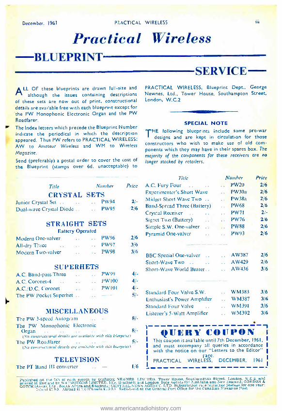
December. 1961 PRACTICAL WIRELESS iii
Practical Wireless BLUEPRINT
ALL OF these blueprints are drawn full -size and
although the issues containing descriptions of these sets are now out of print, constructional details are available free with each blueprint except for the PW Monophonic Electronic Organ and the PW
Road fa re r.
The Index letters which precede the Blueprint Number indicate the periodical in which the description appeared. Thus PW refers to PRACTICAL WIRELESS;
AW to Amateur Wireless and WM to Wireless
Magazine.
Send (preferably) a postal order to cover the cost of
the Blueprint (stamps over 6d. unacceptable) to
SERVICE PRACTICAL WIRELESS, Blueprint Dept., George Newnes, Ltd., Tower House, Southampton Street, London, W.C.2
SPECIAL NOTE THE following blueprints include some pre -war
designs and are kept in circulation for those constructors who wish to make use of old com- ponents which they may have in their spares box. The
majority of the components for these receivers are no
longer stocked by retailers.
Title Number
CRYSTAL SETS Junior Crystal Set .. .. .. PW94
Dual -wave Crystal Diode .. .. PW95
STRAIGHT SETS Eattcry Operated
Modern One -valver PW96
All -dry Three PW97
Modern Two -valver PW98
SUPERHETS A.C. Band -pass Three PW99
A.C. Coronet -4 .. P W l00
A.C. /D.C. Coronet PW101
The PW Pocket Superhet
MISCELLANEOUS
Price
2/-
2/6
2/6 3/6 36
4/-
4E-
4/- 5/-
Title
A.C. Fury Four .. Experimenter's Short Wave
Midget Short Wave Two .. Band- Spread Three (Battery) Crystal Receiver .. Signet Two (Battery) Simple S.W. One -valver
Pyramid One -valver
BBC Special One -valver Short -Wave Two .. Short -Wave World Beater..
Standard Four Valve S.W.
Enthusiast's Power Amplifier Standard Four Valve
Listener's 5 -Watt Amplifier
Number .. PW20
PW 30a
PW38a
PW68
PW71
PW76
PW88
PW93
AW387 AW429 AW436
WM383 WM387 WM391 WM392
Price 2/6 2/6 2/6 2;'6
2/- 2/6
2/6 2/6
2/6 2/6
3/6
3/6 3/6 3/6 3/6
The PW 3- speed Autogram .. - 8/-
The PW Monophonic Electronic Organ .. .. .. .. 8/- (\.o constructional details are available with this blueprint)
The PW Roadfarer .. .. 5i- (,Au constructional details are available with tisis blueprint)
TELEVISION The PT Band III converter .. - 1/6
QUERY CO[Tl'ON This coupon is available until 7th December, 1961,
and must accompany all queries in accordance with the notice on our "Letters to the Editor"
rage. PRACTICAL WIRELESS, DECEMBER, 1961
Published on the 7th of each month by GEORGE NEWNES. LIMITED, Tower House, Southampton Street, London, W.C.2. and printed in England by WATMOUGHS LIMITED, Idle. Bradford: and London. Sole Agents for Australia and New Zealand; GORDON &
GOTCH (A /sial. Ltd., South Africa and Rhodesia: CENTRAL NEWS AGENCY. LTD. Subscription rate including postage for one year: Inland £L9.0. Abroad £1.7.6 (Canada £L5.0.'_ Registered at the General Post Office for the Canadian Magazine Post.
www.americanradiohistory.com

REMEMBER! PRACT'CAL WIRELESS December, 1961
All our Units are covered by After Sales Service and Guarantee Only New Components are Supplied No Technical Knowledge Required
Size 8- x 6¡ x 3 1in. Full coverage on
Medium and Long wave- bands. Excellent quality with full station separa- tion. Car aerial socket.
"TRANSFIVE" PORTABLE MEDIUM AND LONG WAVE
PORTABLE RADIO 325 mW Push -Pull Output on 5 -inch Speaker. Pictorial Euilt ing Plans. Easy to Euild Printed Circuit. 5 Carded Components Mullard Transistors.
AFTER SALES SERVICE and
GUARANTEED FULLY TOTAL COST OF ALL PARTS
£6.19.6 P.P. 2,6 NO EXTRAS TO BUY
" QUINTET " MEDIUM AND LONG WAVE
POCKET LOUDSPEAKER RADIO
250mW Push -Pull Output. Plainly marked Printed Circuit Board and Carded Components. 5 Mallard Transistors. Illustrated Plans.
A. new printed circuit design fully tunable on both wavebands. Guaran- teed reception of Con- tinental and local stations including Luxembourg, anywhere with full station separation. Fitted Car VERY EASY TO BUILD AND USE Aerial and Earpiece After Sales Service and Guarantee Sockets. All Parts Sold Separately
BUILDING PLANS & PRICES FREE ON REQUEST Illustrated Instructions FREE ON REQUEST
`14 1!3, Size 5i x3 x If in.
TOTAL COST OF ALL PARTS
£5.10.0 P.P. 2'- NO EXTRAS TO BUY
* RANGER 3 * NO EXTERNAL AERIAL. OR EARTH -3- TRANSISTOR and
0
2 DIODES All Parts
59 j6 tf P.P. 1'6
;À
CONTESSA 6 TRANSISTOR
LONG
{1 sat la! If , §hip
MEDIUM WAVE SUPERHET
vs
AND
it "sayy
`rs t:iiN ti ;y
ids , \ ^5 ..ty° f
lès "
-
; wil
COMBINED PORTABLE AND CAR RADIO
High "Q" Internal Ferrite Aerial. Car Radio Adaptation and AVC. "H; -Fi" Quality Speaker. Slow Motion Fingertip Tuning with Station names clearly marked. 425mW Push -Pull Output. 6 "Top- Grade" Ediswan Transistors. New Type Printed Circuit with all components marked. Full Medium and Long Wave Tuning. S
Details and Prices on Request
I/jj TOTAL COST OF ALL PARTS
£10.19.6 P.P. 3'6 e NO EXTRAS TO BUY
Attractive Rexine Covered Cabinet Red White or Blue White, 10 x 74 x 3;in.
UNBEATABLE IN PERFORMANCE AND APPEARANCE
I WATT TRANSISTOR AMPLIFIER EMI 4- Transistor Amplifier with
speaker, tone and volume controls. Ready assembled for use with crystal pick -ups. 7; to 9 volt operated 89'6 P.P. l'6. BATTERY RECORD PLAYER
6 -7# volt Garrard Turntable with crystal pickup. Plays 4S r.p.m. Ideal for above amplifier. 79'6 P.P. I t6.
* RANGER 2 *
Size 4} x 3 x I lin.
All Components
79 6 P.P. I'6
Everything Supplied
Personal Pocket Radio with 5 stages giving clear recep- tion on medium wave. amateur top band and shipping.
Easy to follow instructions with pictorial layout. Reception of Radio Luxem- bourg guaran- teed (most areas)
Free Instructions and Price List on request.
WATT 4 TRANSISTOR AMPLIFIER
-,èJ I watt peak output.
yv^ }3db 70c /s to 12 kt/s.
Output to 3
ohm speaker
9 volt oper- ated. Built and Tested
696 P. & P. 1'6 Details on request
A printed circuit high gain amplifier size x 22 x Sin. using Mullard OC7I: OCSI D
and 2 -OC8 I Transistors. Ideal for Inter - comm.. Record Player. Tuner Amplifier cr any application requiring a quality and eliable amplifier.
3- TRANSISTOR AND DIODE PERSONAL POCKET RADIO
Quality Out- put on Person- al Earphone A simple to build local station with personal earphone out- put. Built -in Fer- rite Aerial and Battery lasting 9 months. Size 41 x 3 x I ;in.
ALL PARTS
3Ìs 6 P.P. I t6
PLEASE s Henry's Radio Ltd 411=MINSMEN
PERSONAL POCKET RADIO Two Transistor Two Diode fully
tunable over medium waves. Good reception of Radio Luxembourg. Size 4} x 3 x 1 }in. No extras to buy.
PICTORIAL PLANS AND DETAILS FREE ON REQUEST
Transistor 2 -Way Intercomm
10 gns.
Unit Sizes 31 x l- x 3 #in (Approx.) Internal Buzzing System. Push -Pull Speaker Ou put. Long Life Battery.
Supplied complete with Battery, 60ft. Wire in Presentation box.
Guaranteed and ready to use.
TRANSISTOR PORTABLE TAPE RECORDER
Size 6 x 84 n 2 4in.
Quality Reproduction
SUPPLIED COMPLETE WITH MICROPHONE, BATTERIES, 5 H, ".P..SOW ROAD, PERSONAL PHONE AND TAPE.
Opposite Edgware Road Tube Station, PADdington 1008 9. Built-in Speaker. ' 9 t^ns TURN Open Monday to Saturday, 9 -6, Thursday I o'clo: Play
Speaker. 2 V PAGE SEND 6d. STAMP FOR DETAILS & PRICES CF COMPLETE RANGE. FULLY GUARANTEED
LONDON W2
www.americanradiohistory.com