
Monitoring Power Quality Beyond en 50160 and IEC 61000-4-30 - April 2008
Upload
kenneth-rogersCategory
view
217download
0
Frankfurt (Germany), 6-9 June 2011
EN 50160 voltage dips and swells classification as an instrument for responsibility sharing
Maurizio Delfanti
Department of Energy– Politecnico di Milano
CENELEC TC 8X/WG1 Secretary

Frankfurt (Germany), 6-9 June 2011
TC8X Organization
TC8XSystem Aspects of Electricity Supply
WG 1Physical
Characteristics Of Electrical Energy
WG 3Requirements for
connection of generators to distribution networks
WG 4Endorsement Of IEC 60038 as European
Standard
TF 1 ... 8
WG 5Smart Grid
Requirements
Frankfurt (Germany), 6-9 June 2011
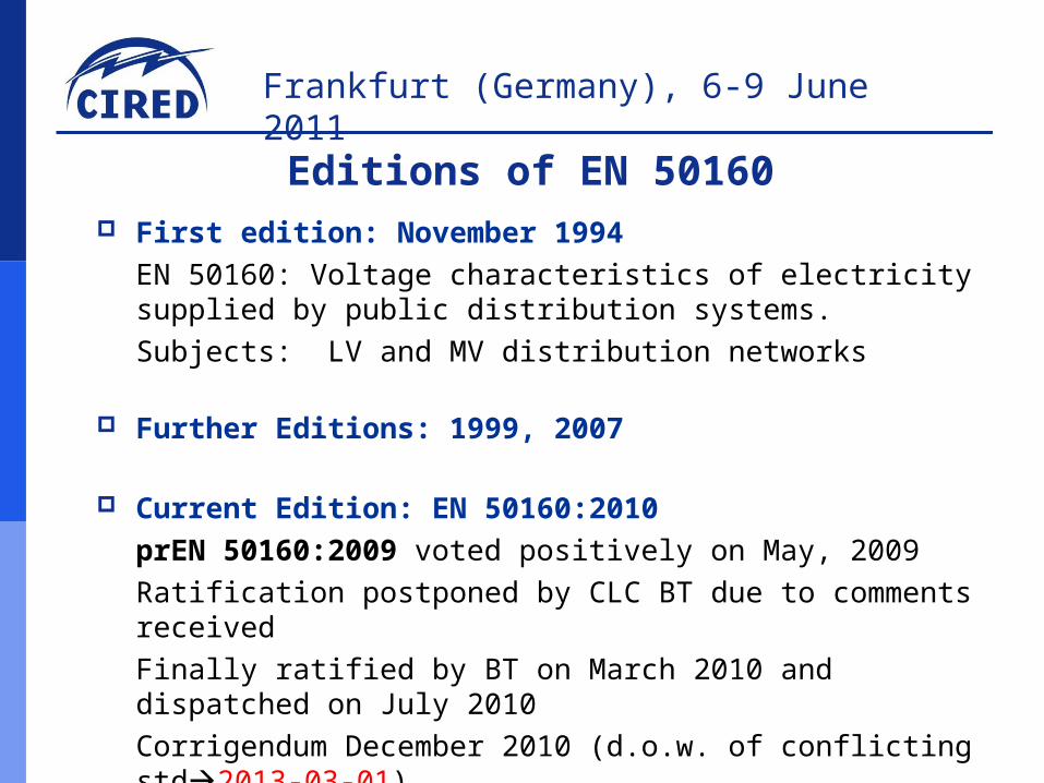
First edition: November 1994
EN 50160: Voltage characteristics of electricity supplied by public distribution systems.
Subjects: LV and MV distribution networks
Further Editions: 1999, 2007
Current Edition: EN 50160:2010
prEN 50160:2009 voted positively on May, 2009
Ratification postponed by CLC BT due to comments received
Finally ratified by BT on March 2010 and dispatched on July 2010
Corrigendum December 2010 (d.o.w. of conflicting std2013-03-01)
Implemented at national level by March,1st 20113
Editions of EN 50160
Frankfurt (Germany), 6-9 June 2011
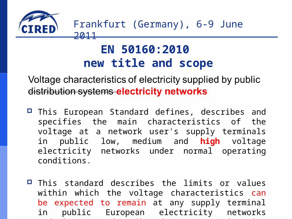
This European Standard defines, describes and specifies the main characteristics of the voltage at a network user's supply terminals in public low, medium and high voltage electricity networks under normal operating conditions.
This standard describes the limits or values within which the voltage characteristics can be expected to remain at any supply terminal in public European electricity networksand does not describe the average situation usually experienced by an individual network user.
4
EN 50160:2010 new title and scope

Frankfurt (Germany), 6-9 June 2011
In the new edition (EN 50160:2010), a distinction is made between:
continuous phenomena, i.e. small deviations from the nominal value that occur continuously over time - such phenomena are mainly due to load pattern, changes of load or nonlinear loads;voltage events, sudden and significant deviations from normal or desired wave shape.
Voltage events are typically due to unpredictable events (e.g., faults) or to external causes (e.g., weather, third party actions)
For some continuous phenomena limits are specified;for voltage events, only indicative values can be given at present.
5
New edition (EN 50160:2010)continuous phenomena / voltage events
Frankfurt (Germany), 6-9 June 2011
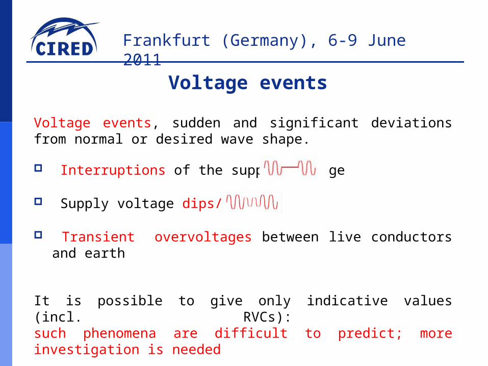
Voltage events, sudden and significant deviations from normal or desired wave shape.
Interruptions of the supply voltage
Supply voltage dips/swells
Transient overvoltages between live conductors and earth
It is possible to give only indicative values (incl. RVCs): such phenomena are difficult to predict; more investigation is needed
6
Voltage events

Frankfurt (Germany), 6-9 June 2011
Definition: a temporary reduction of the voltage at a point in the electrical supply system below a specified start threshold.
Note 1: For the purpose of this standard, the dip start threshold is equal to 90 % of the reference voltage.
Note 2: Typically, a dip is associated with the occurrence and termination of a short circuit or other extreme current increase on the system or installations connected to it.
Note 3: For the purpose of this standard, a voltage dip is a two dimensional electromagnetic disturbance, the level of which is determined by both voltage and time (duration).
7
Voltage events:voltage dips

Frankfurt (Germany), 6-9 June 2011
Reference was made to test levels given in
EN 61000-4-11 (different test levels for different classes: 1, 2, 3, X) EN 61000-4-11 contains a reference to the “network performance”
8
Network performance &equipment test levels
Test levels for appliances in EN 61000-4-11, class 3
It is useful to describe the possible behavior of the network with the same parameters used for testing appliances
(Product Standards)

Frankfurt (Germany), 6-9 June 2011
Measurement uncertainty (addressed in EN 61000-4-30) has to be considered. The duration of a voltage dip depends on the protection strategy adopted,
which may differ from case to case (network structure, neutral earthing, etc) Durations do not necessarily match the boundaries of the columns of the Table.9
The new classification in EN 50160:2010,Tables 2, 5 and 8

Frankfurt (Germany), 6-9 June 2011
For a given class of appliances (f.i., class 3), the cells above the curve represent an immunity area
Classes are referred to different electromagnetic environment, as defined in EN 61000-2-4
Duration t [ms]
Range of res. voltage Ur (in % of Un or Ud) 10 < t ≤ 200 200 < t ≤ 500 500 < t ≤ 5000
90 > Ur ≥ 80 A1 A2 A3+A4
80 > Ur ≥ 70 B1 B2 B3+B4
70 > Ur ≥ 40 C1 C2 C3+C4
40 > Ur ≥ 5 D1 D2 D3+D4
10
Equipment immunity

Frankfurt (Germany), 6-9 June 2011
For the cells below the curve, a regulation can be enforced at a national level
Expected values (for each bus? for each area? for worst served customers?) can be given by TSO/DSO
11
Duration t [ms]
Range of res. voltage Ur (in % of Un or Ud)
10 < t ≤ 200 200 < t ≤ 500 500 < t ≤ 5000
90 > Ur ≥ 80 A1 A2 A3+A4
80 > Ur ≥ 70 B1 B2 B3+B4
70 > Ur ≥ 40 C1 C2 C3+C4
40 > Ur ≥ 5 D1 D2 D3+D4
Voltage quality requirements

Frankfurt (Germany), 6-9 June 2011
As some standard/national documents (France, South Africa) already foresee, it is useful to set a bound between: events for which appliances have to be immune events that can be limited by the DSO/TSO
The concept of a “responsibility sharing curve” is much wider and complex (see next presentation by M. Bollen)
In the new edition of the Standard (EN 50160:2010) the concept has been applied to voltage dips
12
Responsibility sharing curve

Frankfurt (Germany), 6-9 June 2011
This annex is aimed at providing the reader with some information about indicative values currently available at a European level for some of the events defined and described in the standard.
Some information is also given about the way of using values given in the standard, and about the way of collecting further measurement data, in order to allow for comparisons between different systems and to have homogeneous data at a EU level.
As many monitoring systems are in place in some countries, further information is available at a national level.At a national level, more precise figures can be found; furthermore, some regulations may exist.
13
Annex B:B.1 General

Frankfurt (Germany), 6-9 June 2011
QuEEN monitors about 10% of the main MV bus-bars.
The sample is representative of the network characteristics in terms of: number of HV/MV substations per region length of the MV lines type of MV lines: cable, overhead, mixed neutral compensation or isolated neutral number/density of MV/LV customers
The system is managed by RSE
(Ricerca sul Sistema Energetico)
QuEEN: 400 monitoring units installed on MV bus-bars of HV/MV substations

Frankfurt (Germany), 6-9 June 2011
QuEEN report, year 2008(data collected on 10% of MV main busbars)
Average number of dips per bus: 124,1 97,7 voltage dips would be overcome by class 3 equipment 26,4 voltage dips would impair the operation of class 3 equipment
Duration t [ms]
Range of res. voltage Ur (in % of Un or Ud)
10 < t ≤ 200 200 < t ≤ 500 500 < t ≤ 5000
90 > Ur ≥ 80 29,2 5,6 2,0
80 > Ur ≥ 70 18,6 4,3 0,6
70 > Ur ≥ 40 40,0 6,8 0,7
40 > Ur ≥ 5 15,4 2,6 0,3

Frankfurt (Germany), 6-9 June 2011
QuEEN report, year 2009(data collected on 10% of MV main busbars)
Average number of dips per bus: 114,2 95,6 voltage dips would be overcome by class 3 equipment 18,6 voltage dips would impair the operation of class 3 equipment
Duration t [ms]
Range of res. voltage Ur (in % of Un or Ud)
10 < t ≤ 200 200 < t ≤ 500 500 < t ≤ 5000
90 > Ur ≥ 80 34,9 7,5 2,6
80 > Ur ≥ 70 17,1 5,3 0,8
70 > Ur ≥ 40 28,2 5,3 0,7
40 > Ur ≥ 5 9,9 1,7 0,2

Frankfurt (Germany), 6-9 June 2011
QuEEN report, year 2010(data collected on 10% of MV main busbars)
Average number of dips per bus: 98,3 82,4 voltage dips would be overcome by class 3 equipment 15,9 voltage dips would impair the operation of class 3 equipment
Duration t [ms]
Range of res. voltage Ur (in % of Un or Ud)
10 < t ≤ 200 200 < t ≤ 500 500 < t ≤ 5000
90 > Ur ≥ 80 31,5 6,4 2,0
80 > Ur ≥ 70 15,5 4,4 0,6
70 > Ur ≥ 40 22,6 4,8 0,5
40 > Ur ≥ 5 8,5 1,3 0,2

Frankfurt (Germany), 6-9 June 2011
Towards VQ regulation in Italy
Based on the EN 50160:2010, on the data collected by QuEEN,
and on an economic analysis of the impact of microinterruptions
(transient interruptions+voltage dips, PoliMI – DIG 2006) on the Italian economy,
Autorità per l’energia elettrica e il gas published two Consultation Documents
(DCO 42/10; DCO 15/11); some proposals regard:
1)extension of VQ monitoring to all MV busbars of HV/MV stations
(about 4000 VQ meters needed)
2)publication of expected/registered values of microinterruptions
(transient interruptions+voltage dips) by the DSO for each MV main busbar
(publication of long and short interruptions already in force)
The availability of such data would allow a sensitive user to evaluate
on a sound technical base if further immunization / mitigation is needed for his
specific production process (equipment class; UPS; PQ contract).

Frankfurt (Germany), 6-9 June 2011
THANK YOU!
Maurizio Delfanti – Italy – RT 2a


![Standard en 50160 Voltage Characteristics in[1] Copy](https://static.fdocuments.in/doc/165x107/577cc36f1a28aba711960795/standard-en-50160-voltage-characteristics-in1-copy.jpg)