France MEASUREMENTS FOR ASSESSING THE IMPACT OF OOBE AS WELL AS SHORT … · supporting a...
30
T:\ORGCOMMUNICATION\DOCUMENTLIBRARY\RAPPORTS À PUBLIER\TRAVAUX EUROPEENS\R12-JTG4567-C-0418!!MSW-E FRANCE MESURE EFFETS OOB SUR TV.DOCX 07/02/2014 Background Joint Task Group (JTG) 4-5-6-7 developed at its last meeting a set of working documents towards items relating to the broadcasting service for WRC-15 agenda item 1.2. Specifically, in order to assess the impact of adjacent band interference from the mobile service into the broadcasting service. In Document 4-5-6-7/174 the results of the measurements carried out on two DVB-T2 receivers (DVB-T2 Set-Top-Boxes) tend to show that very short pulse interferences (1 ms) from broadband systems (IMT) may lead to long lasting picture errors (1s), when the DTT protection ratios measured for continues interferences is exceeded by only 1 dB. In Document 4-5-6-7/339 the results of measurements carried out on three DVB-T2 receivers show that, for an LTE UE ACLR of 52.83 dB, increasing the DTT receiver selectivity by 26.4 dB through the addition of the inline filter has no effect on protection ratio unless the UE OOB emissions are also reduced. It was felt that more measurements should be carried out to confirm these results. Proposal France invites JTG 4-5-6-7 to consider the results of the measurements presented in this document when discussing the development of IMT UE OOBE limits and to include the relevant parts in the Draft Reports being developed by JTG 4-5-6-7 reflecting the results of studies. 1 Introduction This report presents the results of the measurements carried out on ten different DTTB receivers (DVB-T and DVB-T2 receivers), currently available on the European market, for assessing the impact of short pulse interferences from IMT (LTE) user equipment to DTTB reception on channel 48. It aims at providing information to assist sharing studies for the co-existence of DTTB broadcasting with IMT user equipment. Note that ITU-R Joint Task Group 4-5-6-7 received within the study period many contributions supporting a confirmation of the lower edge at 694 MHz and on the usage of GE06 DTTB channel 48. In addition, JTG 4-5-6-7 took note of the GE06 Plan modification activities based on a lower edge at 694 MHz in parts of Region 1, in particular by ATU and ITU. Radiocommunication Study Groups Received: 5 February 2014 Subject: WRC-15 agenda item 1.2 Document 4-5-6-7/418-E 7 February 2014 English only France MEASUREMENTS FOR ASSESSING THE IMPACT OF OOBE AS WELL AS SHORT PULSE INTERFERENCES FROM IMT USER EQUIPMENT TO DTTB RECEPTION
Transcript of France MEASUREMENTS FOR ASSESSING THE IMPACT OF OOBE AS WELL AS SHORT … · supporting a...

T:\ORGCOMMUNICATION\DOCUMENTLIBRARY\RAPPORTS À PUBLIER\TRAVAUX EUROPEENS\R12-JTG4567-C-0418!!MSW-E FRANCE MESURE EFFETS OOB SUR TV.DOCX 07/02/2014
Background
Joint Task Group (JTG) 4-5-6-7 developed at its last meeting a set of working documents towards items relating to the broadcasting service for WRC-15 agenda item 1.2. Specifically, in order to assess the impact of adjacent band interference from the mobile service into the broadcasting service.
In Document 4-5-6-7/174 the results of the measurements carried out on two DVB-T2 receivers (DVB-T2 Set-Top-Boxes) tend to show that very short pulse interferences (1 ms) from broadband systems (IMT) may lead to long lasting picture errors (1s), when the DTT protection ratios measured for continues interferences is exceeded by only 1 dB.
In Document 4-5-6-7/339 the results of measurements carried out on three DVB-T2 receivers show that, for an LTE UE ACLR of 52.83 dB, increasing the DTT receiver selectivity by 26.4 dB through the addition of the inline filter has no effect on protection ratio unless the UE OOB emissions are also reduced.
It was felt that more measurements should be carried out to confirm these results.
Proposal
France invites JTG 4-5-6-7 to consider the results of the measurements presented in this document when discussing the development of IMT UE OOBE limits and to include the relevant parts in the Draft Reports being developed by JTG 4-5-6-7 reflecting the results of studies.
1 Introduction This report presents the results of the measurements carried out on ten different DTTB receivers (DVB-T and DVB-T2 receivers), currently available on the European market, for assessing the impact of short pulse interferences from IMT (LTE) user equipment to DTTB reception on channel 48. It aims at providing information to assist sharing studies for the co-existence of DTTB broadcasting with IMT user equipment.
Note that ITU-R Joint Task Group 4-5-6-7 received within the study period many contributions supporting a confirmation of the lower edge at 694 MHz and on the usage of GE06 DTTB channel 48. In addition, JTG 4-5-6-7 took note of the GE06 Plan modification activities based on a lower edge at 694 MHz in parts of Region 1, in particular by ATU and ITU.
Radiocommunication Study Groups
Received: 5 February 2014
Subject: WRC-15 agenda item 1.2
Document 4-5-6-7/418-E
7 February 2014
English only
France
MEASUREMENTS FOR ASSESSING THE IMPACT OF OOBE AS WELL AS SHORT PULSE INTERFERENCES FROM IMT USER EQUIPMENT
TO DTTB RECEPTION
- 2 - 4-5-6-7/418-E
T:\ORGCOMMUNICATION\DOCUMENTLIBRARY\RAPPORTS À PUBLIER\TRAVAUX EUROPEENS\R12-JTG4567-C-0418!!MSW-E FRANCE MESURE EFFETS OOB SUR TV.DOCX 07/02/2014
Thus JTG 4-5-6-7 decided to propose to WRC-15 that the lower edge be confirmed at 694 MHz whilst protecting the GE06 DTTB channel 48 and below through appropriate technical and regulatory mechanisms based on the results of the studies.
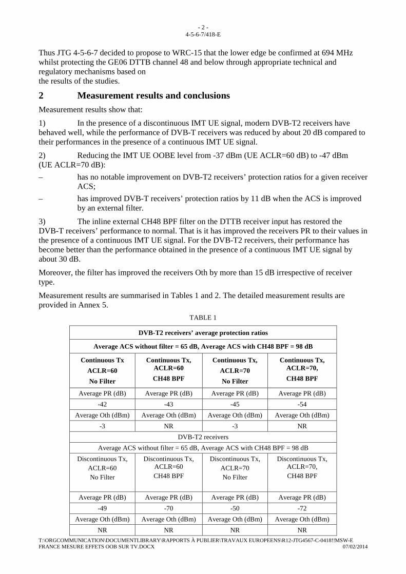
2 Measurement results and conclusions Measurement results show that:
1) In the presence of a discontinuous IMT UE signal, modern DVB-T2 receivers have behaved well, while the performance of DVB-T receivers was reduced by about 20 dB compared to their performances in the presence of a continuous IMT UE signal.
2) Reducing the IMT UE OOBE level from -37 dBm (UE ACLR=60 dB) to -47 dBm (UE ACLR=70 dB):
– has no notable improvement on DVB-T2 receivers’ protection ratios for a given receiver ACS;
– has improved DVB-T receivers’ protection ratios by 11 dB when the ACS is improved by an external filter.
3) The inline external CH48 BPF filter on the DTTB receiver input has restored the DVB-T receivers’ performance to normal. That is it has improved the receivers PR to their values in the presence of a continuous IMT UE signal. For the DVB-T2 receivers, their performance has become better than the performance obtained in the presence of a continuous IMT UE signal by about 30 dB.
Moreover, the filter has improved the receivers Oth by more than 15 dB irrespective of receiver type.
Measurement results are summarised in Tables 1 and 2. The detailed measurement results are provided in Annex 5.
TABLE 1
DVB-T2 receivers’ average protection ratios
Average ACS without filter = 65 dB, Average ACS with CH48 BPF = 98 dB
Continuous Tx
ACLR=60
No Filter
Continuous Tx, ACLR=60
CH48 BPF
Continuous Tx,
ACLR=70
No Filter
Continuous Tx, ACLR=70,
CH48 BPF
Average PR (dB) Average PR (dB) Average PR (dB) Average PR (dB)
-42 -43 -45 -54
Average Oth (dBm) Average Oth (dBm) Average Oth (dBm) Average Oth (dBm)
-3 NR -3 NR
DVB-T2 receivers
Average ACS without filter = 65 dB, Average ACS with CH48 BPF = 98 dB
Discontinuous Tx, ACLR=60 No Filter
Discontinuous Tx, ACLR=60 CH48 BPF
Discontinuous Tx, ACLR=70 No Filter
Discontinuous Tx, ACLR=70, CH48 BPF
Average PR (dB) Average PR (dB) Average PR (dB) Average PR (dB)
-49 -70 -50 -72
Average Oth (dBm) Average Oth (dBm) Average Oth (dBm) Average Oth (dBm)
NR NR NR NR

- 3 - 4-5-6-7/418-E
T:\ORGCOMMUNICATION\DOCUMENTLIBRARY\RAPPORTS À PUBLIER\TRAVAUX EUROPEENS\R12-JTG4567-C-0418!!MSW-E FRANCE MESURE EFFETS OOB SUR TV.DOCX 07/02/2014
TABLE 2
DVB-T receivers’ average protection ratios
Average ACS without filter = 62 dB, Average ACS with CH48 BPF = 95 dB
Continuous Tx
ACLR=60
Continuous Tx, ACLR=60
CH48 BPF
Continuous Tx,
ACLR=70
Continuous Tx, ACLR=70,
CH48 BPF
Average PR (dB) Average PR (dB) Average PR (dB) Average PR (dB)
-40 -41 -43 -54
Average Oth (dBm) Average Oth (dBm) Average Oth (dBm) Average Oth (dBm)
-2 NR -2 NR
DVB-T receivers
Average ACS without filter = 62 dB, Average ACS with CH48 BPF = 95 dB
Discontinuous Tx ACLR=60
Discontinuous Tx, ACLR=60 CH48 BPF
Discontinuous Tx, ACLR=70
Discontinuous Tx, ACLR=70, CH48 BPF
Average PR (dB) Average PR (dB) Average PR (dB) Average PR (dB)
-22 -42 -23 -53
Average Oth (dBm) Average Oth (dBm) Average Oth (dBm) Average Oth (dBm)
-5 NR -4 NR
The conclusions drawn from the results of the measurements are summarized below:
– The tested DTTB receivers have behaved very similarly in the presence of a continuous IMT UE signal, while they have behaved very differently one from the other in the presence of a discontinuous (time varying) IMT UE signal. The ACS of the DTTB receivers tested are in the range of 62 to 65 dB.
– Modern DVB-T2 receivers are behaving well in the presence of a discontinuous interfering signal. Actually, the modern DVB-T2 receivers tested have behaved better in the presence of a discontinuous IMT UE signal than in the presence of a continuous IMT UE signal, while the performance of DVB-T receivers was reduced by about 20 dB.
– The impact of discontinuous IMT UE emissions on DTTB reception can only be efficiently combated by improving DTTB receivers’ AGC circuits, including the overall ACS of the receivers : improving the ACLR of IMT UE signal does not improve the protection ratio
– The values of ACLR and ACS should be similar in magnitude for obtaining the best performance in reduction and filtering of out of band emissions.
– For the protection of the broadcasting service, the ACLR of IMT UE signal should be fixed by taking into account the impact of a continuous IMT UE signal on DTTB reception as well as the implementation cost of IMT UE filtering

- 4 - 4-5-6-7/418-E
T:\ORGCOMMUNICATION\DOCUMENTLIBRARY\RAPPORTS À PUBLIER\TRAVAUX EUROPEENS\R12-JTG4567-C-0418!!MSW-E FRANCE MESURE EFFETS OOB SUR TV.DOCX 07/02/2014
3 Abbreviations ACLR Adjacent Channel Leakage Ratio
ACG Automatic Gain Control
C/I Signal-to-interference ratio
DTTB Digital Terrestrial Television Broadcasting
IBE In Band Emissions
OOBE Out Of Band Emissions
Oth Overloading threshold
PR Protection ratio
RB Resource block - a unit of data transmission in LTE, represented by a certain number of carriers in a uplink or downlink symbol in the frequency domain
TM Transmission Mode
TTI Transmission Time Interval
UE User equipment - the mobile handset
See Annex 2 for further useful definitions
4 References
4.1 Broadcasting technology characteristics
The following references contain the characteristics of the different broadcast systems including transmitter spectrum masks:
– DVB-T system characteristics: Recommendation ITU-R BT.1306, ETSI EN 300 744;
– DVB-T2 system characteristics: Recommendation ITU-R BT.1877, ETSI EN 302 755;
– Planning criteria, including protection ratios, for digital terrestrial television services in the VHF/UHF bands: Recommendation ITU-R BT.1368.
4.2 Mobile technology characteristics
The following references contain the characteristics of the different mobile broadband systems.
– LTE system characteristics: ETSI TS 136.101.
5 Measurement methodology and system parameters
5.1 Test set-up used
The test setup for protection ratio and overloading threshold measurements is depicted in Figure 1.

- 5 - 4-5-6-7/418-E
T:\ORGCOMMUNICATION\DOCUMENTLIBRARY\RAPPORTS À PUBLIER\TRAVAUX EUROPEENS\R12-JTG4567-C-0418!!MSW-E FRANCE MESURE EFFETS OOB SUR TV.DOCX 07/02/2014
FIGURE 1
Measurements set-up
An adjustable band-pass filter (1) was inserted between the interfering signal generator and the combiner. The objective of this filter is to eliminate the wideband noise generated by the interfering signal generator and adjust the interfering signal to the correct interference transmission mask and ACLR values. An isolator was also inserted between the DVB-T signal generator and the combiner to keep the power from the interfering signal generator returning to the DVB-T signal generator output.
A CH48 BPF (2) has been used to reduce the UE in band (IB) emissions falling into DTTB CH48 and consequently to identify the predominate component of the interfering UE emissions, which are composed of UE IB and OOB emissions, on the DTTB reception. Further details on this filter can be found in section 4.7.
The test equipment used is presented in Table A.1 in Annex 1.
DVB-T receiver
IMT (LTE)
signal generator
Interfering signal
Wanted signal
DVB-T/T2
signal generator
MPEG2/4
video source
Observer
Screen
Adjustable
band-pass filter (1)
Combiner
Isolator
Variable
attenuator
Video
recorder
Adjustable CH48
band-pass filter
Spectrum Analyzer

- 6 - 4-5-6-7/418-E
T:\ORGCOMMUNICATION\DOCUMENTLIBRARY\RAPPORTS À PUBLIER\TRAVAUX EUROPEENS\R12-JTG4567-C-0418!!MSW-E FRANCE MESURE EFFETS OOB SUR TV.DOCX 07/02/2014
5.2 System parameters
TABLE 3
System parameters
DVB-T parameters
Parameter Value Comments
Centre frequency (MHz) 690 Channel 48
Channel raster (MHz) 8 MHz
DVB-T2 : Modulation : FFTsize: Coding rate: Guard interval: Throughput per multiplex: C/N (dB):
64 QAM 8k ext
3/4 1/8 (112µs)
24.882 Mbps 18
Configuration used in France
Gaussian channel
DVB-T2 : Modulation : FFTsize: Coding rate: Guard interval: Pilot profile: # OFDM symbols /Frame: Throughput per multiplex: C/N (dB):
256 QAM 32k ext
3/5 1/16 (224µs)
PP4 62
33.177 Mbps 18 dB
Configuration foreseen in France
Gaussian channel
Content HD video streams
Measured average
receiver sensitivity (dBm)
-78.8
Wanted signal
levels used (dBm)
-70, -60, -50, -40, -30 and -20 In order to properly determine the PR and Oth
IMT UE parameters
Parameter Value Comments
Centre frequency (MHz) 708
Channel raster (MHz) 10
Modulation SC-FDMA
Number of RBs used 5, 10, 20 et 50
Max UE power (dBm) 23 20.82 dBm was used for tests
OOBE in DTTB CH 48 (dBm/8MHz)
-37 and -47 UE ACLRCH481= 60 and 70 dB,
with full IMT UE resource allocation (50 RBs)

- 7 - 4-5-6-7/418-E
T:\ORGCOMMUNICATION\DOCUMENTLIBRARY\RAPPORTS À PUBLIER\TRAVAUX EUROPEENS\R12-JTG4567-C-0418!!MSW-E FRANCE MESURE EFFETS OOB SUR TV.DOCX 07/02/2014
Transmission mode Continuous and
discontinuous (burst)
Maximum
transmission duration (s)
0.001 1 Transmission time interval (TTI)
Transmission
period (s)
1 and 5
1UE ACLRCH48 (dB) = UE IBE power (dBm/10MHz) measured at 708 MHz- UE OOBE power (dBm/8MHz) measured at 690 MHz
5.3 Wanted signal levels
Protection ratios (PR) and overloading thresholds (Oth) of a receiver are derived from its C(I) curves. The measurements have been carried out by using different DVB-T/T2 wanted signal levels to cover the range from weakest to strongest signals: -70, -60, -50 ,-40, -30 and -20 dBm. At low wanted signal levels the protection ratio limit is usually reached before the overloading threshold. Therefore it is necessary to use higher wanted signal levels to reach the onset of overload.
5.4 Frequency offsets between IMT UE interfering signal and DTTB wanted signal
A single frequency offset has been used (18 MHz) aiming at limiting the number of measurement to be carried out. This frequency offset corresponds to a guard band (GB) of 9 MHz between DTTB centered at 690 MHz and the IMT UE signal centered at 708 MHz as shown in Figure 2.
FIGURE 2
Frequency offsets between IMT UE and DTTB signals
5.5 Generation of the IMT uplink signal
The uplink signal can vary considerably in both the time and frequency domains depending upon the traffic loading required. In the frequency domain the number of RBs allocated for each SC-FDMA symbol can vary rapidly. Maximum number of RBs is 50. In the time domain, there can be long periods where the UE does not transmit at all, leading to an irregular pulse like power profile. The minimum duration of UE transmission time interval is 1ms (1 TTI), while the duration of a basic radio frame is 10 ms (10 TTI).
DTTB
CH48 IMT UE
703 MHz 694 MHz 686 MHz 803 MHz
∆f = 18 MHz fc=690 MHz fc=708 MHz
GB = 9 MHz

- 8 - 4-5-6-7/418-E
T:\ORGCOMMUNICATION\DOCUMENTLIBRARY\RAPPORTS À PUBLIER\TRAVAUX EUROPEENS\R12-JTG4567-C-0418!!MSW-E FRANCE MESURE EFFETS OOB SUR TV.DOCX 07/02/2014
In this measurement campaign three different UE transmission modes have been used:
– Continuous transmission (TM1);
– Discontinuous transmission (TM2) with: UE signal maximum transmission duration = 1 ms, transmission period = 1 s;
– Discontinuous transmission (TM3) with: UE signal maximum transmission duration = 1 ms, transmission period = 5 s.
The UE generator output power was fixed to 20.83 dBm. Two different ACLR values, 60 and 70 dB, have been used in measurements. These ACLR values were obtained by means of an inline band pass filter (BPF) on UE signal generator. They correspond respectively to -37 and -47 dBm/8MHz, for an IMT UE maximum transmit power of 23 dBm, in case of full uplink resource allocation (50 RBs).
The spectrum of IMT UE TM1 signal having an ACLR of 60 dB is shown in Figure 3.
FIGURE 3
Spectrum of IMT UE TM1 signal having an ACLR of 60 dB
The spectrum of IMT UE TM2 signal having an ACLR of 60 dB is shown in Figure 4, while the time domain shape of the signal is shown in Figures 6 and 7.

- 9 - 4-5-6-7/418-E
T:\ORGCOMMUNICATION\DOCUMENTLIBRARY\RAPPORTS À PUBLIER\TRAVAUX EUROPEENS\R12-JTG4567-C-0418!!MSW-E FRANCE MESURE EFFETS OOB SUR TV.DOCX 07/02/2014
FIGURE 4
Spectrum of IMT UE TM2 signal having an ACLR of 60 dB
FIGURE 5
Spectrum of IMT UE TM1 signal having an ACLR of 70 dB

- 10 - 4-5-6-7/418-E
T:\ORGCOMMUNICATION\DOCUMENTLIBRARY\RAPPORTS À PUBLIER\TRAVAUX EUROPEENS\R12-JTG4567-C-0418!!MSW-E FRANCE MESURE EFFETS OOB SUR TV.DOCX 07/02/2014
FIGURE 6
IMT UE TM2 signal having an ACLR of 60 dB on the time domain.
Detail of one pulse
FIGURE 7
IMT UE TM2 signal having an ACLR of 60 dB on the time domain.
Detail of several pulses
- 11 - 4-5-6-7/418-E
T:\ORGCOMMUNICATION\DOCUMENTLIBRARY\RAPPORTS À PUBLIER\TRAVAUX EUROPEENS\R12-JTG4567-C-0418!!MSW-E FRANCE MESURE EFFETS OOB SUR TV.DOCX 07/02/2014
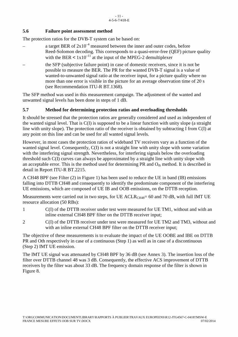
5.6 Failure point assessment method
The protection ratios for the DVB-T system can be based on:
– a target BER of 2x10⁻⁴ measured between the inner and outer codes, before Reed-Solomon decoding. This corresponds to a quasi-error-free (QEF) picture quality with the BER < 1x10–11 at the input of the MPEG-2 demultiplexer
– the SFP (subjective failure point) in case of domestic receivers, since it is not be possible to measure the BER. The PR for the wanted DVB-T signal is a value of wanted-to-unwanted signal ratio at the receiver input, for a picture quality where no more than one error is visible in the picture for an average observation time of 20 s (see Recommendation ITU-R BT.1368).
The SFP method was used in this measurement campaign. The adjustment of the wanted and unwanted signal levels has been done in steps of 1 dB.
5.7 Method for determining protection ratios and overloading thresholds
It should be stressed that the protection ratios are generally considered and used as independent of the wanted signal level. That is C(I) is supposed to be a linear function with unity slope (a straight line with unity slope). The protection ratio of the receiver is obtained by subtracting I from C(I) at any point on this line and can be used for all wanted signal levels.
However, in most cases the protection ratios of wideband TV receivers vary as a function of the wanted signal level. Consequently, C(I) is not a straight line with unity slope with some variation with the interfering signal strength. Nevertheless, for interfering signals below the overloading threshold such C(I) curves can always be approximated by a straight line with unity slope with an acceptable error. This is the method used for determining PR and Oth method. It is described in detail in Report ITU-R BT.2215.
A CH48 BPF (see Filter (2) in Figure 1) has been used to reduce the UE in band (IB) emissions falling into DTTB CH48 and consequently to identify the predominate component of the interfering UE emissions, which are composed of UE IB and OOB emissions, on the DTTB reception.
Measurements were carried out in two steps, for UE ACLRCH48= 60 and 70 dB, with full IMT UE resource allocation (50 RBs):
1 C(I) of the DTTB receiver under test were measured for UE TM1, without and with an inline external CH48 BPF filter on the DTTB receiver input;
2 C(I) of the DTTB receiver under test were measured for UE TM2 and TM3, without and with an inline external CH48 BPF filter on the DTTB receiver input;
The objective of these measurements is to evaluate the impact of the UE OOBE and IBE on DTTB PR and Oth respectively in case of a continuous (Step 1) as well as in case of a discontinuous (Step 2) IMT UE emission.
The IMT UE signal was attenuated by CH48 BPF by 36 dB (see Annex 3). The insertion loss of the filter over DTTB channel 48 was 3 dB. Consequently, the effective ACS improvement of DTTB receivers by the filter was about 33 dB. The frequency domain response of the filter is shown in Figure 8.

- 12 - 4-5-6-7/418-E
T:\ORGCOMMUNICATION\DOCUMENTLIBRARY\RAPPORTS À PUBLIER\TRAVAUX EUROPEENS\R12-JTG4567-C-0418!!MSW-E FRANCE MESURE EFFETS OOB SUR TV.DOCX 07/02/2014
FIGURE 8
Frequency domain response of CH48 BPF centered at 690 MHz
The ACS of the tested DTTB receivers are presented in Table 4 (see Annex 4 for more detailed information).
TABLE 4
Calculated DVB-T/T2 receivers’ adjacent channel selectivity
Continuous IMT UE transmission, UE ACLR=60 dB
DTTB Receiver
ACS without
CH48 filter (dB)
ACS with
CH48 filter (dB)
Rx1 (DVB-T2) 62 95
Rx2 (DVB-T2) 72 105
Rx3 (DVB-T) 62 95
Rx4 (DVB-T2) 60 93
Rx5 (DVB-T2) 65 98
Rx6 (DVB-T) 62 95
Rx7 (DVB-T2) 72 105
Rx8 (DVB-T) 72 105
Rx9 (DVB-T) 62 95
Rx10 (DVB-T) 54 87
DVB-T2 average value 65 98
DVB-T average value 62 95

- 13 - 4-5-6-7/418-E
T:\ORGCOMMUNICATION\DOCUMENTLIBRARY\RAPPORTS À PUBLIER\TRAVAUX EUROPEENS\R12-JTG4567-C-0418!!MSW-E FRANCE MESURE EFFETS OOB SUR TV.DOCX 07/02/2014
6 Measurement results The measured C(I) curves have been post processed, according to the method described in Report ITU-R BT.2215, in order to determine the PR and Oth of the tested DTTB receivers. The results obtained are presented in the following sections.
6.1 Measurement results with an IMT UE ACLR of 60 dB
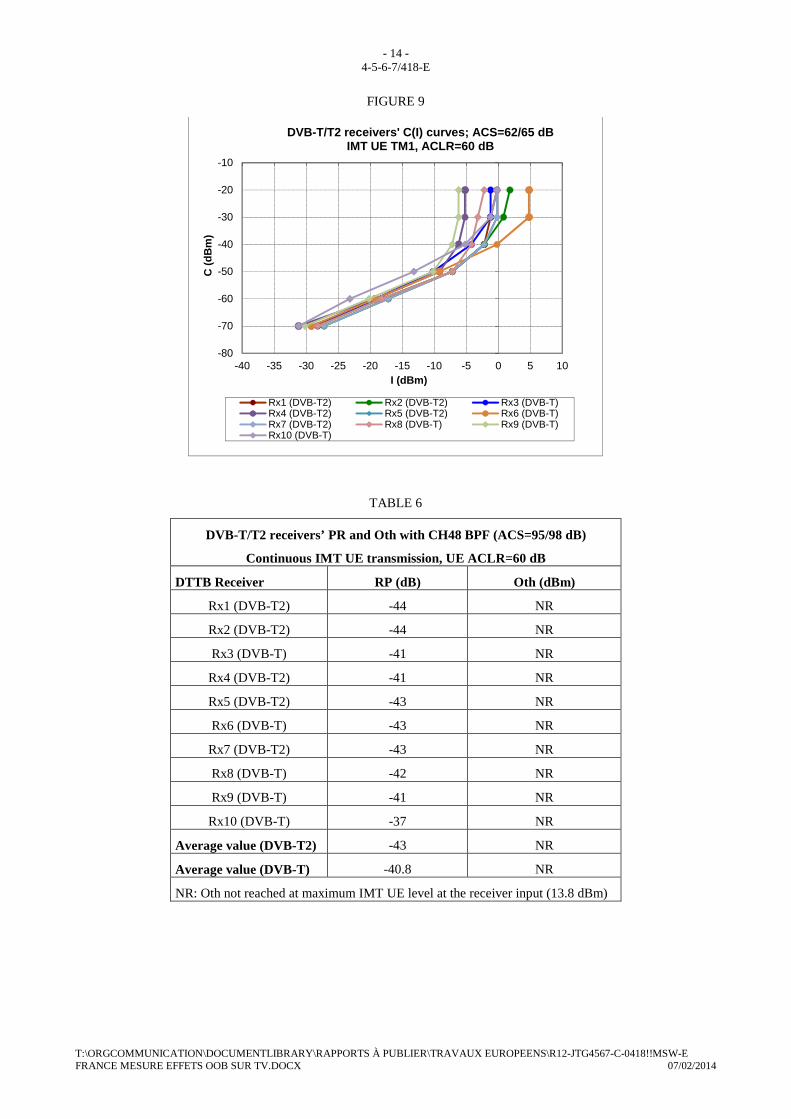
6.1.1 DTTB receivers PR and Oth values in the presence of a continuous IMT UE signal (TM1)
The PR and Oth of the tested DTTB receivers, in the presence of an IMT UE TM1 signal, are presented in Tables 5 and 6, while C(I) curves are shown in Figures 9 and 10.
TABLE 5
DVB-T/T2 receivers’ PR and Oth without CH48 BPF (ACS=62/65 dB)
Continuous IMT UE transmission, UE ACLR=60 dB
DTTB Receiver RP (dB) Oth (dBm)
Rx1 (DVB-T2) -41 -2
Rx2 (DVB-T2) -43 -2
Rx3 (DVB-T) -40 -4
Rx4 (DVB-T2) -39 -6
Rx5 (DVB-T2) -42 -2
Rx6 (DVB-T) -41 5
Rx7 (DVB-T2) -43 -2
Rx8 (DVB-T) -42 -4
Rx9 (DVB-T) -40 -7
Rx10 (DVB-T) -35 -1
Average value (DVB-T2) -41.6 -2,8
Average value (DVB-T) -39.6 -2,2
- 14 - 4-5-6-7/418-E
T:\ORGCOMMUNICATION\DOCUMENTLIBRARY\RAPPORTS À PUBLIER\TRAVAUX EUROPEENS\R12-JTG4567-C-0418!!MSW-E FRANCE MESURE EFFETS OOB SUR TV.DOCX 07/02/2014
FIGURE 9
TABLE 6
DVB-T/T2 receivers’ PR and Oth with CH48 BPF (ACS=95/98 dB)
Continuous IMT UE transmission, UE ACLR=60 dB
DTTB Receiver RP (dB) Oth (dBm)
Rx1 (DVB-T2) -44 NR
Rx2 (DVB-T2) -44 NR
Rx3 (DVB-T) -41 NR
Rx4 (DVB-T2) -41 NR
Rx5 (DVB-T2) -43 NR
Rx6 (DVB-T) -43 NR
Rx7 (DVB-T2) -43 NR
Rx8 (DVB-T) -42 NR
Rx9 (DVB-T) -41 NR
Rx10 (DVB-T) -37 NR
Average value (DVB-T2) -43 NR
Average value (DVB-T) -40.8 NR
NR: Oth not reached at maximum IMT UE level at the receiver input (13.8 dBm)
-80
-70
-60
-50
-40
-30
-20
-10
-40 -35 -30 -25 -20 -15 -10 -5 0 5 10
C (
dBm
)
I (dBm)
DVB-T/T2 receivers' C(I) curves; ACS=62/65 dBIMT UE TM1, ACLR=60 dB
Rx1 (DVB-T2) Rx2 (DVB-T2) Rx3 (DVB-T)Rx4 (DVB-T2) Rx5 (DVB-T2) Rx6 (DVB-T)Rx7 (DVB-T2) Rx8 (DVB-T) Rx9 (DVB-T)Rx10 (DVB-T)
- 15 - 4-5-6-7/418-E
T:\ORGCOMMUNICATION\DOCUMENTLIBRARY\RAPPORTS À PUBLIER\TRAVAUX EUROPEENS\R12-JTG4567-C-0418!!MSW-E FRANCE MESURE EFFETS OOB SUR TV.DOCX 07/02/2014
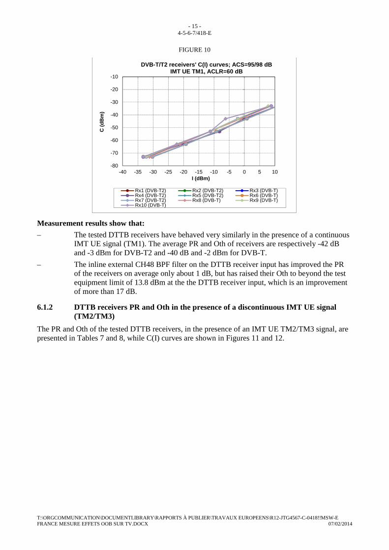
FIGURE 10
Measurement results show that:
– The tested DTTB receivers have behaved very similarly in the presence of a continuous IMT UE signal (TM1). The average PR and Oth of receivers are respectively -42 dB and -3 dBm for DVB-T2 and -40 dB and -2 dBm for DVB-T.
– The inline external CH48 BPF filter on the DTTB receiver input has improved the PR of the receivers on average only about 1 dB, but has raised their Oth to beyond the test equipment limit of 13.8 dBm at the the DTTB receiver input, which is an improvement of more than 17 dB.
6.1.2 DTTB receivers PR and Oth in the presence of a discontinuous IMT UE signal (TM2/TM3)
The PR and Oth of the tested DTTB receivers, in the presence of an IMT UE TM2/TM3 signal, are presented in Tables 7 and 8, while C(I) curves are shown in Figures 11 and 12.
-80
-70
-60
-50
-40
-30
-20
-10
-40 -35 -30 -25 -20 -15 -10 -5 0 5 10
C (
dBm
)
I (dBm)
DVB-T/T2 receivers' C(I) curves; ACS=95/98 dBIMT UE TM1, ACLR=60 dB
Rx1 (DVB-T2) Rx2 (DVB-T2) Rx3 (DVB-T)Rx4 (DVB-T2) Rx5 (DVB-T2) Rx6 (DVB-T)Rx7 (DVB-T2) Rx8 (DVB-T) Rx9 (DVB-T)Rx10 (DVB-T)

- 16 - 4-5-6-7/418-E
T:\ORGCOMMUNICATION\DOCUMENTLIBRARY\RAPPORTS À PUBLIER\TRAVAUX EUROPEENS\R12-JTG4567-C-0418!!MSW-E FRANCE MESURE EFFETS OOB SUR TV.DOCX 07/02/2014
TABLE 7
DVB-T/T2 receivers’ PR and Oth without CH48 BPF (ACS=62/65 dB)
Discontinuous IMT UE transmission, UE ACLR=60 dB
DTTB Receiver RP (dB) Oth (dBm)
Rx1 (DVB-T2) -30/-591 NR
Rx2 (DVB-T2) -60 NR
Rx3 (DVB-T) -23 -5
Rx4 (DVB-T2) -302 NR
Rx5 (DVB-T2) -563 NR
Rx6 (DVB-T) -264 NR
Rx7 (DVB-T2) -33/-635 NR
Rx8 (DVB-T) -25 -5
Rx9 (DVB-T) -12 NR
Rx10 (DVB-T) -23 -4
Average value (DVB-T2) -496 NR
Average value (DVB-T) -22 -5
NR: not reached at maximum IMT UE level at the receiver input (13.8 dBm)
1. With hysteresis at C=-40 dBm
2. -72 dB at C≥-60 dBm
3. Interference only at C=-70 dBm (PR=-56), no interference for C>-70 dBm at maximum IMT UE level (13.8 dBm) at the receiver input
4. PR=-36 dB with break at C=-40 dBm
5. With hysteresis at C=-60 dBm
6. Rx1 and Rx7 were excluded (first generation DVB-T2 receivers from the same manufacturer)
- 17 - 4-5-6-7/418-E
T:\ORGCOMMUNICATION\DOCUMENTLIBRARY\RAPPORTS À PUBLIER\TRAVAUX EUROPEENS\R12-JTG4567-C-0418!!MSW-E FRANCE MESURE EFFETS OOB SUR TV.DOCX 07/02/2014
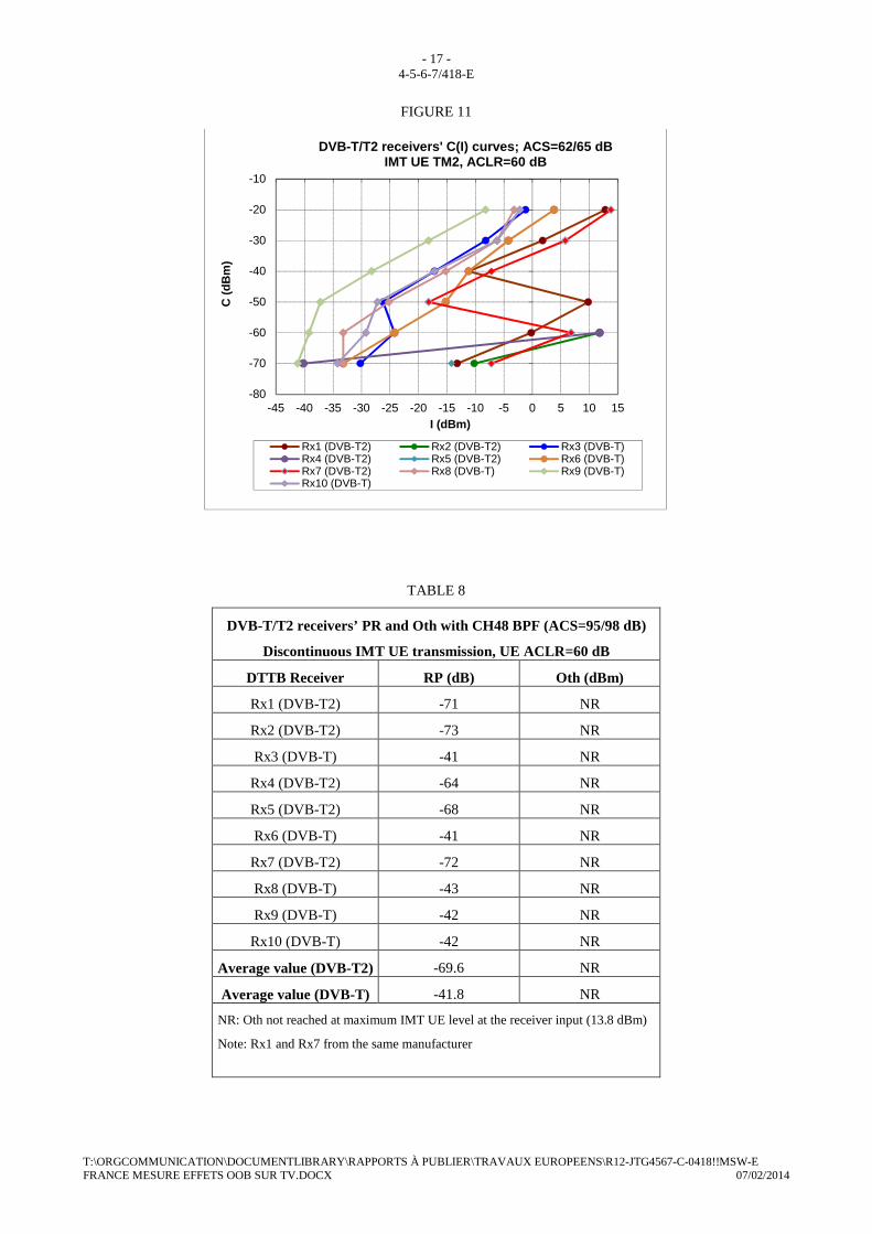
FIGURE 11
TABLE 8
DVB-T/T2 receivers’ PR and Oth with CH48 BPF (ACS=95/98 dB)
Discontinuous IMT UE transmission, UE ACLR=60 dB
DTTB Receiver RP (dB) Oth (dBm)
Rx1 (DVB-T2) -71 NR
Rx2 (DVB-T2) -73 NR
Rx3 (DVB-T) -41 NR
Rx4 (DVB-T2) -64 NR
Rx5 (DVB-T2) -68 NR
Rx6 (DVB-T) -41 NR
Rx7 (DVB-T2) -72 NR
Rx8 (DVB-T) -43 NR
Rx9 (DVB-T) -42 NR
Rx10 (DVB-T) -42 NR
Average value (DVB-T2) -69.6 NR
Average value (DVB-T) -41.8 NR
NR: Oth not reached at maximum IMT UE level at the receiver input (13.8 dBm)
Note: Rx1 and Rx7 from the same manufacturer
-80
-70
-60
-50
-40
-30
-20
-10
-45 -40 -35 -30 -25 -20 -15 -10 -5 0 5 10 15
C (
dBm
)
I (dBm)
DVB-T/T2 receivers' C(I) curves; ACS=62/65 dBIMT UE TM2, ACLR=60 dB
Rx1 (DVB-T2) Rx2 (DVB-T2) Rx3 (DVB-T)Rx4 (DVB-T2) Rx5 (DVB-T2) Rx6 (DVB-T)Rx7 (DVB-T2) Rx8 (DVB-T) Rx9 (DVB-T)Rx10 (DVB-T)
- 18 - 4-5-6-7/418-E
T:\ORGCOMMUNICATION\DOCUMENTLIBRARY\RAPPORTS À PUBLIER\TRAVAUX EUROPEENS\R12-JTG4567-C-0418!!MSW-E FRANCE MESURE EFFETS OOB SUR TV.DOCX 07/02/2014
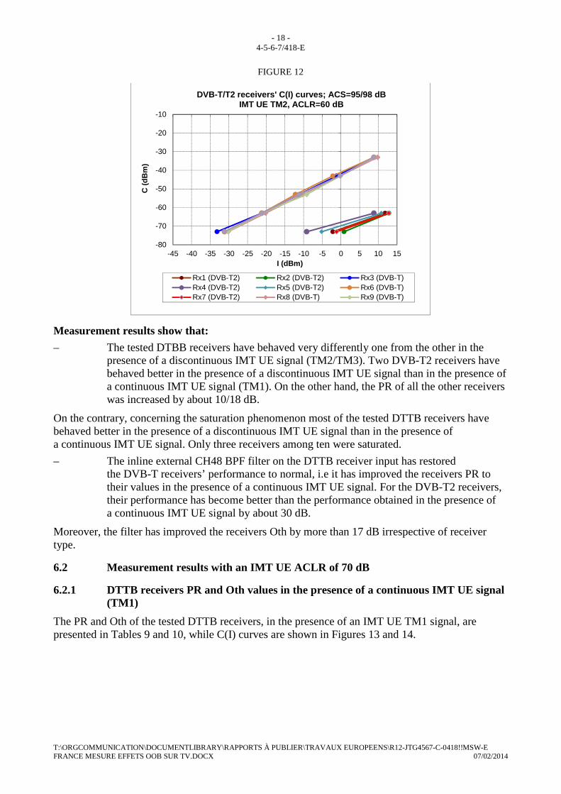
FIGURE 12
Measurement results show that:
– The tested DTBB receivers have behaved very differently one from the other in the presence of a discontinuous IMT UE signal (TM2/TM3). Two DVB-T2 receivers have behaved better in the presence of a discontinuous IMT UE signal than in the presence of a continuous IMT UE signal (TM1). On the other hand, the PR of all the other receivers was increased by about 10/18 dB.
On the contrary, concerning the saturation phenomenon most of the tested DTTB receivers have behaved better in the presence of a discontinuous IMT UE signal than in the presence of a continuous IMT UE signal. Only three receivers among ten were saturated.
– The inline external CH48 BPF filter on the DTTB receiver input has restored the DVB-T receivers’ performance to normal, i.e it has improved the receivers PR to their values in the presence of a continuous IMT UE signal. For the DVB-T2 receivers, their performance has become better than the performance obtained in the presence of a continuous IMT UE signal by about 30 dB.
Moreover, the filter has improved the receivers Oth by more than 17 dB irrespective of receiver type.
6.2 Measurement results with an IMT UE ACLR of 70 dB
6.2.1 DTTB receivers PR and Oth values in the presence of a continuous IMT UE signal (TM1)
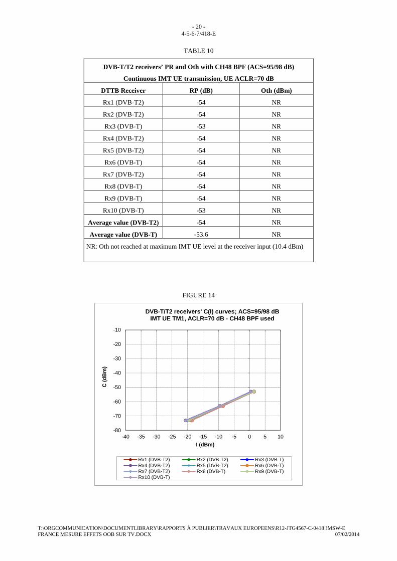
The PR and Oth of the tested DTTB receivers, in the presence of an IMT UE TM1 signal, are presented in Tables 9 and 10, while C(I) curves are shown in Figures 13 and 14.
-80
-70
-60
-50
-40
-30
-20
-10
-45 -40 -35 -30 -25 -20 -15 -10 -5 0 5 10 15
C (
dBm
)
I (dBm)
DVB-T/T2 receivers' C(I) curves; ACS=95/98 dBIMT UE TM2, ACLR=60 dB
Rx1 (DVB-T2) Rx2 (DVB-T2) Rx3 (DVB-T)Rx4 (DVB-T2) Rx5 (DVB-T2) Rx6 (DVB-T)Rx7 (DVB-T2) Rx8 (DVB-T) Rx9 (DVB-T)
- 19 - 4-5-6-7/418-E
T:\ORGCOMMUNICATION\DOCUMENTLIBRARY\RAPPORTS À PUBLIER\TRAVAUX EUROPEENS\R12-JTG4567-C-0418!!MSW-E FRANCE MESURE EFFETS OOB SUR TV.DOCX 07/02/2014
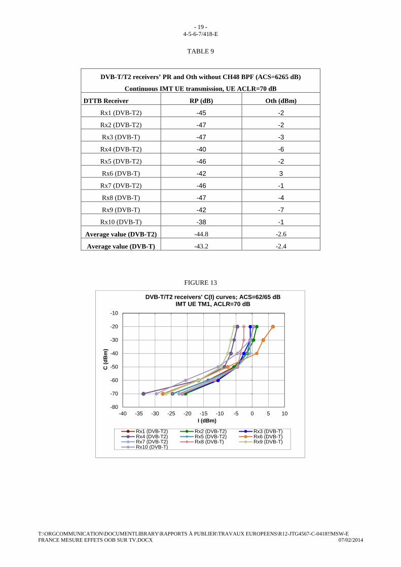
TABLE 9
DVB-T/T2 receivers’ PR and Oth without CH48 BPF (ACS=6265 dB)
Continuous IMT UE transmission, UE ACLR=70 dB
DTTB Receiver RP (dB) Oth (dBm)
Rx1 (DVB-T2) -45 -2
Rx2 (DVB-T2) -47 -2
Rx3 (DVB-T) -47 -3
Rx4 (DVB-T2) -40 -6
Rx5 (DVB-T2) -46 -2
Rx6 (DVB-T) -42 3
Rx7 (DVB-T2) -46 -1
Rx8 (DVB-T) -47 -4
Rx9 (DVB-T) -42 -7
Rx10 (DVB-T) -38 -1
Average value (DVB-T2) -44.8 -2.6
Average value (DVB-T) -43.2 -2.4
FIGURE 13
-80
-70
-60
-50
-40
-30
-20
-10
-40 -35 -30 -25 -20 -15 -10 -5 0 5 10
C (
dBm
)
I (dBm)
DVB-T/T2 receivers' C(I) curves; ACS=62/65 dBIMT UE TM1, ACLR=70 dB
Rx1 (DVB-T2) Rx2 (DVB-T2) Rx3 (DVB-T)Rx4 (DVB-T2) Rx5 (DVB-T2) Rx6 (DVB-T)Rx7 (DVB-T2) Rx8 (DVB-T) Rx9 (DVB-T)Rx10 (DVB-T)
- 20 - 4-5-6-7/418-E
T:\ORGCOMMUNICATION\DOCUMENTLIBRARY\RAPPORTS À PUBLIER\TRAVAUX EUROPEENS\R12-JTG4567-C-0418!!MSW-E FRANCE MESURE EFFETS OOB SUR TV.DOCX 07/02/2014
TABLE 10
DVB-T/T2 receivers’ PR and Oth with CH48 BPF (ACS=95/98 dB)
Continuous IMT UE transmission, UE ACLR=70 dB
DTTB Receiver RP (dB) Oth (dBm)
Rx1 (DVB-T2) -54 NR
Rx2 (DVB-T2) -54 NR
Rx3 (DVB-T) -53 NR
Rx4 (DVB-T2) -54 NR
Rx5 (DVB-T2) -54 NR
Rx6 (DVB-T) -54 NR
Rx7 (DVB-T2) -54 NR
Rx8 (DVB-T) -54 NR
Rx9 (DVB-T) -54 NR
Rx10 (DVB-T) -53 NR
Average value (DVB-T2) -54 NR
Average value (DVB-T) -53.6 NR
NR: Oth not reached at maximum IMT UE level at the receiver input (10.4 dBm)
FIGURE 14
-80
-70
-60
-50
-40
-30
-20
-10
-40 -35 -30 -25 -20 -15 -10 -5 0 5 10
C (
dBm
)
I (dBm)
DVB-T/T2 receivers' C(I) curves; ACS=95/98 dBIMT UE TM1, ACLR=70 dB - CH48 BPF used
Rx1 (DVB-T2) Rx2 (DVB-T2) Rx3 (DVB-T)Rx4 (DVB-T2) Rx5 (DVB-T2) Rx6 (DVB-T)Rx7 (DVB-T2) Rx8 (DVB-T) Rx9 (DVB-T)Rx10 (DVB-T)

- 21 - 4-5-6-7/418-E
T:\ORGCOMMUNICATION\DOCUMENTLIBRARY\RAPPORTS À PUBLIER\TRAVAUX EUROPEENS\R12-JTG4567-C-0418!!MSW-E FRANCE MESURE EFFETS OOB SUR TV.DOCX 07/02/2014
Measurement results show that:
– The tested DTTB receivers have behaved very similarly in the presence of a continuous IMT UE signal (TM1). The average PR and Oth of receivers are respectively -44 dB and -3 dBm.
Reducing the IMT UE OOBE level from -37 dBm (UE ACLR=60 dB) to -47 dBm (UE ACLR=70 dB), without improving the DTTB receivers’ ACS, has no notable improvement on DTTB receivers’ PR (only 3 dB improvement for 10 dB UE ACLR reduction). No improvement on the DTTB receivers’ Oth has been observed.
– The inline external CH48 BPF filter on the DTTB receiver input has improved the PR of the receivers on average by about 11/13 dB and has raised their Oth to beyond the test equipment limit of 10.4 dBm at the the DTTB receiver input, which is an improvement of more than 17 dB.
6.2.2 DTTB receivers PR and Oth in the presence of a discontinuous IMT UE signal (TM2/TM3)
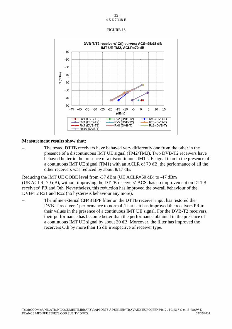
The PR and Oth of the tested DTTB receivers, in the presence of an IMT UE TM2/TM3 signal, are presented in Tables 11 and 12, while C(I) curves are shown in Figures 15 and 16.
TABLE 11
DVB-T/T2 receivers’ PR and Oth without CH48 BPF (ACS=62/65 dB)
Discontinuous IMT UE transmission, UE ACLR=70 dB
DTTB Receiver RP (dB) Oth (dBm)
Rx1 (DVB-T2) -55 NR
Rx2 (DVB-T2) -64 NR
Rx3 (DVB-T) -23 -5
Rx4 (DVB-T2) -311 NR
Rx5 (DVB-T2) -562 NR
Rx6 (DVB-T) -26 NR
Rx7 (DVB-T2) -65 NR
Rx8 (DVB-T) -31 -4
Rx9 (DVB-T) -12 NR
Rx10 (DVB-T) -24 -4
Average value (DVB-T2) -503 NR
Average value (DVB-T) -23 -4.3
NR: not reached at maximum IMT UE level at the receiver input (10.4 dBm)
1. -72 dB at C≥-60 dBm
2. Interference only at C=-70 dBm (PR=-56), no interference for C>-70 dBm at maximum IMT UE level (10.4 dBm) at the receiver input
3. Rx1 and Rx7 were excluded (first generation DVB-T2 receivers from the same manufacturer)

- 22 - 4-5-6-7/418-E
T:\ORGCOMMUNICATION\DOCUMENTLIBRARY\RAPPORTS À PUBLIER\TRAVAUX EUROPEENS\R12-JTG4567-C-0418!!MSW-E FRANCE MESURE EFFETS OOB SUR TV.DOCX 07/02/2014
FIGURE 15
TABLE 12
DVB-T/T2 receivers’ PR and Oth with CH48 BPF (ACS=95/98 dB)
Discontinuous IMT UE transmission, UE ACLR=70 dB
DTTB Receiver RP (dB) Oth (dBm)
Rx1 (DVB-T2) -73 NR
Rx2 (DVB-T2) -74 NR
Rx3 (DVB-T) -54 NR
Rx4 (DVB-T2) -67 NR
Rx5 (DVB-T2) -71 NR
Rx6 (DVB-T) -53 NR
Rx7 (DVB-T2) -74 NR
Rx8 (DVB-T) -54 NR
Rx9 (DVB-T) -53 NR
Rx10 (DVB-T) -53 NR
Average value (DVB-T2) -71.8 NR
Average value (DVB-T) -53.4 NR
NR: Oth not reached at maximum IMT UE level at the receiver input (10.4 dBm)
Note: Rx1 and Rx7 from the same manufacturer
-80
-70
-60
-50
-40
-30
-20
-10
-45 -40 -35 -30 -25 -20 -15 -10 -5 0 5 10 15
C (
dBm
)
I (dBm)
DVB-T/T2 receivers' C(I) curves; ACS=62/65 dBIMT UE TM2, ACLR=70 dB
Rx1 (DVB-T2) Rx2 (DVB-T2) Rx3 (DVB-T)Rx4 (DVB-T2) Rx5 (DVB-T2) Rx6 (DVB-T)Rx7 (DVB-T2) Rx8 (DVB-T) Rx9 (DVB-T)Rx10 (DVB-T)
- 23 - 4-5-6-7/418-E
T:\ORGCOMMUNICATION\DOCUMENTLIBRARY\RAPPORTS À PUBLIER\TRAVAUX EUROPEENS\R12-JTG4567-C-0418!!MSW-E FRANCE MESURE EFFETS OOB SUR TV.DOCX 07/02/2014
FIGURE 16
Measurement results show that:
– The tested DTTB receivers have behaved very differently one from the other in the presence of a discontinuous IMT UE signal (TM2/TM3). Two DVB-T2 receivers have behaved better in the presence of a discontinuous IMT UE signal than in the presence of a continuous IMT UE signal (TM1) with an ACLR of 70 dB, the performance of all the other receivers was reduced by about 8/17 dB.
Reducing the IMT UE OOBE level from -37 dBm (UE ACLR=60 dB) to -47 dBm (UE ACLR=70 dB), without improving the DTTB receivers’ ACS, has no improvement on DTTB receivers’ PR and Oth. Nevertheless, this reduction has improved the overall behaviour of the DVB-T2 Rx1 and Rx2 (no hysteresis behaviour any more).
– The inline external CH48 BPF filter on the DTTB receiver input has restored the DVB-T receivers’ performance to normal. That is it has improved the receivers PR to their values in the presence of a continuous IMT UE signal. For the DVB-T2 receivers, their performance has become better than the performance obtained in the presence of a continuous IMT UE signal by about 30 dB. Moreover, the filter has improved the receivers Oth by more than 15 dB irrespective of receiver type.
-80
-70
-60
-50
-40
-30
-20
-10
-45 -40 -35 -30 -25 -20 -15 -10 -5 0 5 10 15
C (
dBm
)
I (dBm)
DVB-T/T2 receivers' C(I) curves; ACS=95/98 dBIMT UE TM2, ACLR=70 dB
Rx1 (DVB-T2) Rx2 (DVB-T2) Rx3 (DVB-T)Rx4 (DVB-T2) Rx5 (DVB-T2) Rx6 (DVB-T)Rx7 (DVB-T2) Rx8 (DVB-T) Rx9 (DVB-T)Rx10 (DVB-T)

- 24 - 4-5-6-7/418-E
T:\ORGCOMMUNICATION\DOCUMENTLIBRARY\RAPPORTS À PUBLIER\TRAVAUX EUROPEENS\R12-JTG4567-C-0418!!MSW-E FRANCE MESURE EFFETS OOB SUR TV.DOCX 07/02/2014
ANNEX 1 Table A.1 - Test equipment used
Equipment Type
MPEG TS generator Flux TS Player de R&S du SFE
DVB-T/T2 signal generator Rhode & Schwartz Broadcaster Tester SFE
LTE UE signal generator SMU200A de Rohde&Schwarz
RF isolator Radial - 404613
RF combiner Global Professionnel SPLIT-2N-PRO
Adjustable band-pass filter CH48
TELECTRONIV BERKELEY INC
Mod Tif : 750-3-5EE1
Adjustable band-pass filter UE
TDF 00107222 TEXSCAN
Microwave product
Variable attenuator Radial R418035 Radial R418040 Radila R418045
50 / 75 Ohm impedance matching transformer
ANZAC TPX-75-4
Spectrum analyzer Agilent PXA

- 25 - 4-5-6-7/418-E
T:\ORGCOMMUNICATION\DOCUMENTLIBRARY\RAPPORTS À PUBLIER\TRAVAUX EUROPEENS\R12-JTG4567-C-0418!!MSW-E FRANCE MESURE EFFETS OOB SUR TV.DOCX 07/02/2014
ANNEX 2
Useful definitions
Radio frequency signal-to-interference ratio (C/I)
It is the ratio, generally expressed in dB, of the power of the wanted signal to the total power of interfering signals and noise, evaluated at the receiver input (see Recommendation ITU-R V.573). The power of the wanted signal is measured in a bandwidth equal to the wanted signal bandwidth, while the total power of interfering signal and noise is measured in a bandwidth equal to the interfering signal bandwidth.
Radio frequency protection ratio (PR)
It is the minimum value of the signal-to-interference ratio required to obtain a specified reception quality under specified conditions at the receiver input (note that this differs from the definition in Recommendation ITU-R V.573). In this Report, the “specified reception quality” and the “specified conditions” have been defined separately by each entity that has undertaken measurements.
Usually, PR is specified as a function of the frequency offset between the wanted and interfering signals over a wide frequency range. In this Report, PR specified in this way is referred to as “PR curve”. PR curves show the ability of a receiver to discriminate against interfering signals on frequencies differing from that of the wanted signal.
Receiver (front-end) overloading threshold
Overloading threshold (Oth) is the interfering signal level expressed in dBm, above which the receiver begins to lose its ability to discriminate against interfering signals at frequencies differing from that of the wanted signal (i.e., the onset of strong non-linear behaviour). Therefore, above the overloading threshold the receiver will behave in a non-linear way, but does not necessarily fail immediately depending on the receiver and interference characteristics.
Adjacent channel leakage power ratio
Adjacent channel leakage power ratio (ACLR) is the ratio of the filtered mean power centred on the assigned channel frequency to the filtered mean power centred on an adjacent channel frequency. The requirements shall apply whatever the type of transmitter considered (single carrier or multi-carrier). It applies for all transmission modes foreseen by the manufacturer's specification. For a multi-carrier base station (BS), the requirement applies for the adjacent channel frequencies below the lowest carrier frequency transmitted by the BS and above the highest carrier frequency transmitted by the BS for each supported multi-carrier transmission configuration. The requirement applies during the transmitter ON period.
“Can” tuners
“Can” tuners are classical superheterodyne tuners housed in a metal enclosure containing discrete components. Classically, there are fixed and tuneable circuits made up from discrete inductors and transistors usually with varactor diode frequency control. The metal enclosure should minimize RF interference and eliminate crosstalk and stray radiation.
“Silicon” tuners
“Silicon” tuners are IC-based tuners integrating all tuner circuitry into a small package directly to be fitted onto main boards. The tuned circuits may be completely absent or can be integrated onto the silicon. The silicon chip may be protected from external electromagnetic interference by a metallic cover. Silicon tuners have different characteristics to can tuners and their performance can

- 26 - 4-5-6-7/418-E
T:\ORGCOMMUNICATION\DOCUMENTLIBRARY\RAPPORTS À PUBLIER\TRAVAUX EUROPEENS\R12-JTG4567-C-0418!!MSW-E FRANCE MESURE EFFETS OOB SUR TV.DOCX 07/02/2014
be better and worse at some frequency offsets compared to can tuners. This technology is still developing.
ANNEX 3
CH48 BPF filter attenuation on the IMT UE signal
(No spectrum shaping filter)
FIGURE A.3.1
IMT UE signal at the input of CH48 filter

- 27 - 4-5-6-7/418-E
T:\ORGCOMMUNICATION\DOCUMENTLIBRARY\RAPPORTS À PUBLIER\TRAVAUX EUROPEENS\R12-JTG4567-C-0418!!MSW-E FRANCE MESURE EFFETS OOB SUR TV.DOCX 07/02/2014
FIGURE A.3.2
IMT UE signal at the output of CH48 filter

- 28 - 4-5-6-7/418-E
T:\ORGCOMMUNICATION\DOCUMENTLIBRARY\RAPPORTS À PUBLIER\TRAVAUX EUROPEENS\R12-JTG4567-C-0418!!MSW-E FRANCE MESURE EFFETS OOB SUR TV.DOCX 07/02/2014
ANNEX 4
Frequency
offset:
fi-fw (MHz)
Measured DTTB PR (dB)
Measured DTTB Co-CH PR (dB)
Measured DTTB Adj CH PR (dB)
Calculated ACIR (dB)
Measured IMT UE ACLR (dB)
ACIR (linear) ACLR (linear) ACS (dB)
CH48 filter attenuation (dB)
Improved ACS (dB)
18 Rx1 17 -41 58 60,3 1,58489E-06 9,33254E-07 62 33 95
18 Rx2 17 -43 60 0,000001 9,33254E-07 72 105
18 Rx3 18 -40 58 1,58489E-06 9,33254E-07 62 95
18 Rx4 18 -39 57 1,99526E-06 9,33254E-07 60 93
18 Rx5 17 -42 59 1,25893E-06 9,33254E-07 65 98
18 Rx6 17 -41 58 1,58489E-06 9,33254E-07 62 95
18 Rx7 17 -43 60 0,000001 9,33254E-07 72 105
18 Rx8 18 -42 60 0,000001 9,33254E-07 72 105
18 Rx9 18 -40 58 1,58489E-06 9,33254E-07 62 95
18 Rx10 18 -35 53 5,01187E-06 9,33254E-07 54 87
Average ACS DVB-
T2 65 98
Average ACS DVB-T 62 95
Table A.3 - Calculated DTTB receiver adjacent channel selectivity
The receiver adjacent channel selectivity (ACS) has been calculated by the following equation:

- 29 - 4-5-6-7/418-E
T:\ORGCOMMUNICATION\DOCUMENTLIBRARY\RAPPORTS À PUBLIER\TRAVAUX EUROPEENS\R12-JTG4567-C-0418!!MSW-E FRANCE MESURE EFFETS OOB SUR TV.DOCX 07/02/2014
)1010log(10)( 10/10/)( 0 ACLRPRPRdBACS −− −−=
where
ACLR: Adjacent channel leakage ratio of the generated IMT UE signal;
PR: Measured adjacent channel protection ratio;
PR0 : Measured co-channel protection ratio (fi-fw = 0 MHz),
where f i is the center frequency of the interfering signal and
fw is the center frequency of the wanted signal.

- 30 - 4-5-6-7/418-E
T:\ORGCOMMUNICATION\DOCUMENTLIBRARY\RAPPORTS À PUBLIER\TRAVAUX EUROPEENS\R12-JTG4567-C-0418!!MSW-E FRANCE MESURE EFFETS OOB SUR TV.DOCX 07/02/2014
ANNEX 5
Detailed measurement results
French_measuremen
t_results_JTG4567_280114_.xlsx
______________