Framework For Upstream Synchronization and Alignment
24
1 Framework For Upstream Synchronization and Alignment Jeff Mandin PMC-Sierra
-
Upload
mannix-rogers -
Category
Documents
-
view
37 -
download
1
description
Framework For Upstream Synchronization and Alignment. Jeff Mandin PMC-Sierra. Agenda. Design Criteria Logical stack Data Detector Burst mode locking sequence Annex: Rate Adaptation. Design Criteria – System. ONU transmits 10101… pattern during AGC and CDR phases - PowerPoint PPT Presentation
Transcript of Framework For Upstream Synchronization and Alignment

1
Framework For Upstream Synchronization and Alignment
Jeff MandinPMC-Sierra
2
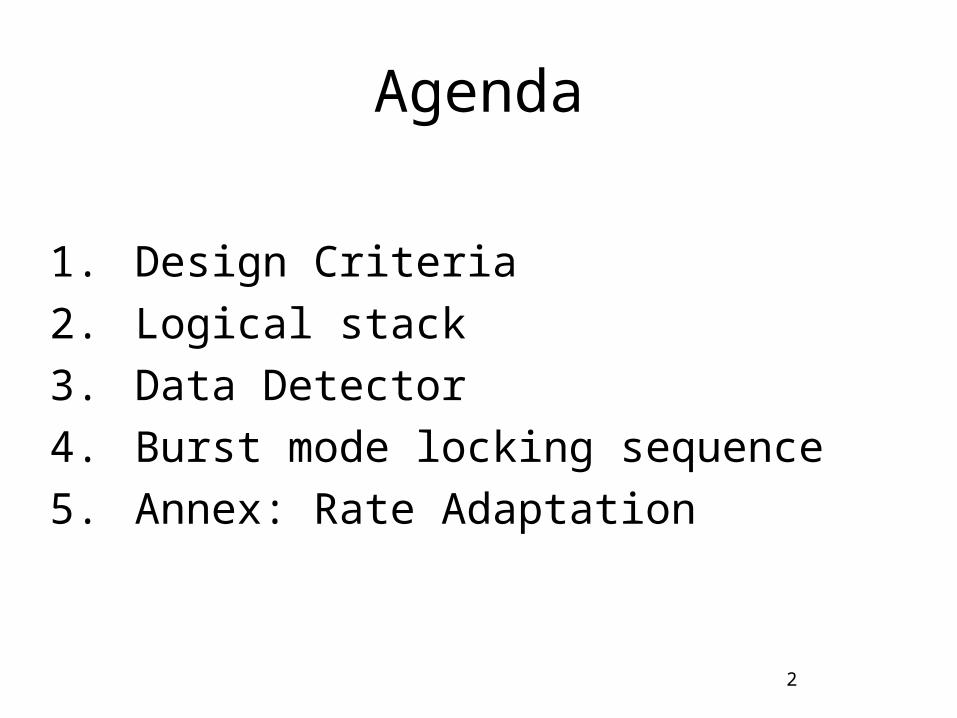
Agenda
1. Design Criteria
2. Logical stack
3. Data Detector
4. Burst mode locking sequence
5. Annex: Rate Adaptation
3
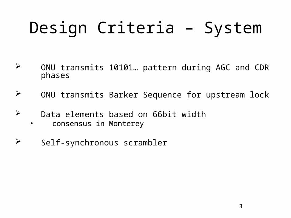
Design Criteria – System
ONU transmits 10101… pattern during AGC and CDR phases
ONU transmits Barker Sequence for upstream lock
Data elements based on 66bit width• consensus in Monterey
Self-synchronous scrambler
4
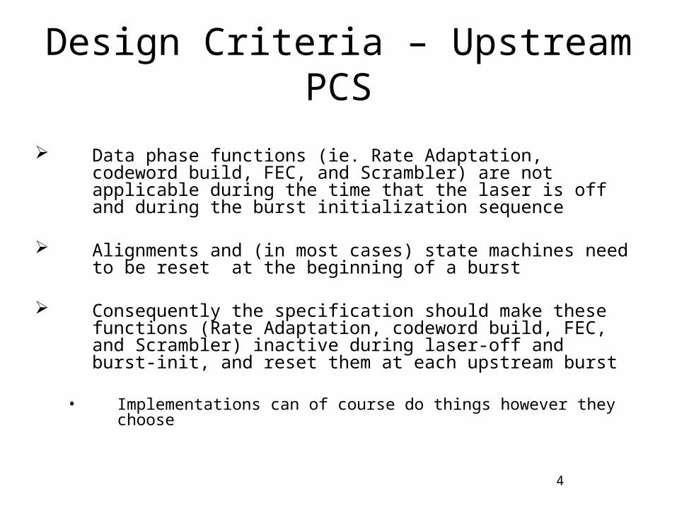
Design Criteria – Upstream PCS
Data phase functions (ie. Rate Adaptation, codeword build, FEC, and Scrambler) are not applicable during the time that the laser is off and during the burst initialization sequence
Alignments and (in most cases) state machines need to be reset at the beginning of a burst
Consequently the specification should make these functions (Rate Adaptation, codeword build, FEC, and Scrambler) inactive during laser-off and burst-init, and reset them at each upstream burst
• Implementations can of course do things however they choose
5
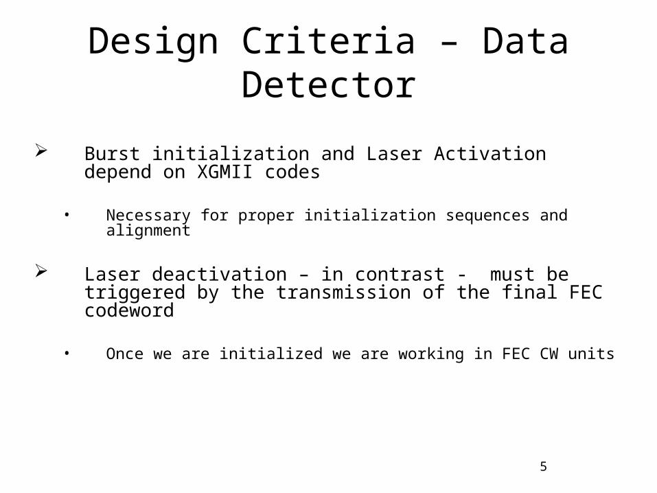
Design Criteria – Data Detector
Burst initialization and Laser Activation depend on XGMII codes
• Necessary for proper initialization sequences and alignment
Laser deactivation – in contrast - must be triggered by the transmission of the final FEC codeword
• Once we are initialized we are working in FEC CW units

6
Logical Stack
7
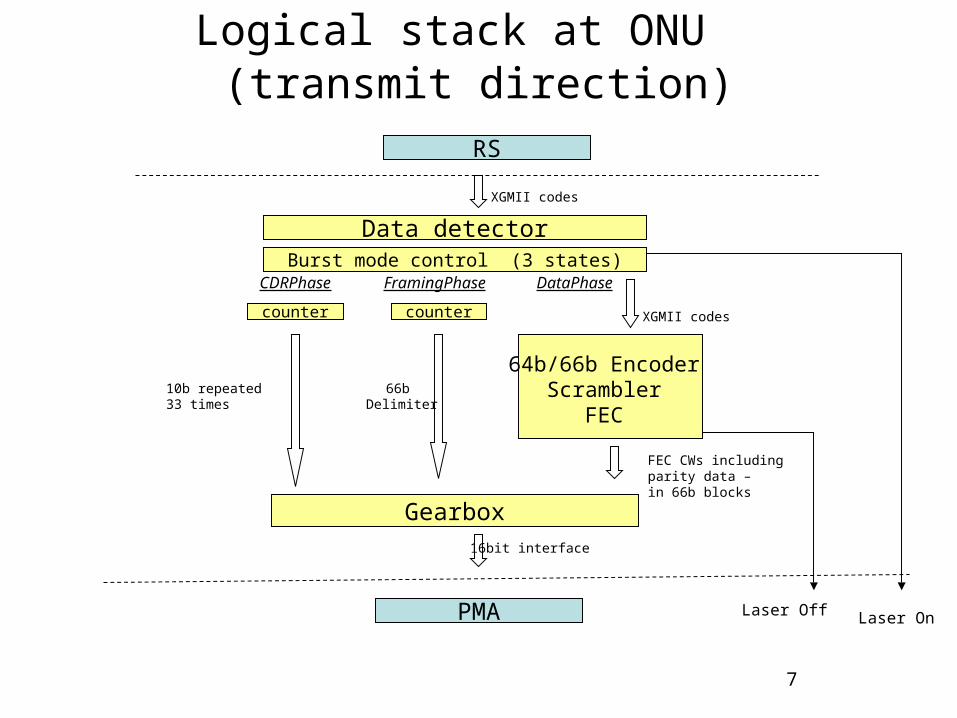
Logical stack at ONU (transmit direction)
Data detector
RS
PMA
FEC CWs includingparity data – in 66b blocks
XGMII codes
10b repeated 33 times
Burst mode control (3 states)
Gearbox16bit interface
66b Delimiter
64b/66b Encoder Scrambler
FEC
XGMII codes
counter counter
CDRPhase FramingPhase DataPhase
Laser OnLaser Off
8
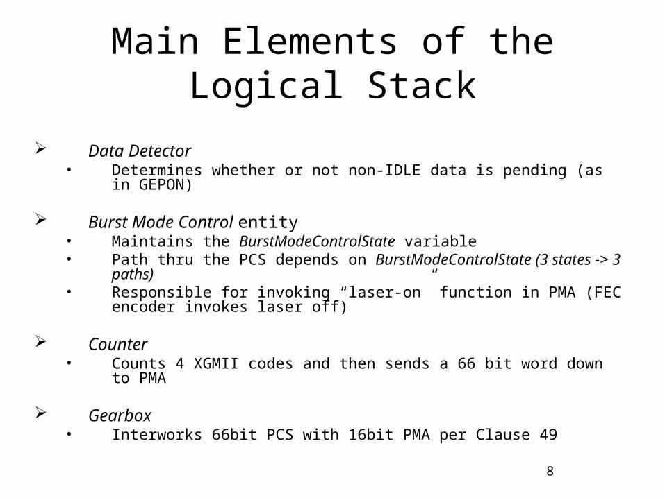
Main Elements of the Logical Stack
Data Detector • Determines whether or not non-IDLE data is pending (as in GEPON)
Burst Mode Control entity• Maintains the BurstModeControlState variable • Path thru the PCS depends on BurstModeControlState (3 states -> 3
paths)• Responsible for invoking “laser-on” function in PMA (FEC encoder
invokes laser off)
Counter• Counts 4 XGMII codes and then sends a 66 bit word down to PMA
Gearbox• Interworks 66bit PCS with 16bit PMA per Clause 49
9
Data Detector
10
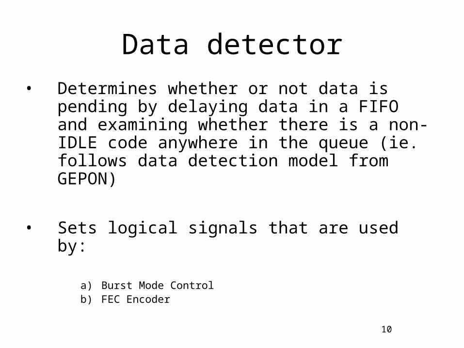
Data detector
• Determines whether or not data is pending by delaying data in a FIFO and examining whether there is a non-IDLE code anywhere in the queue (ie. follows data detection model from GEPON)
• Sets logical signals that are used by:
a) Burst Mode Controlb) FEC Encoder
11
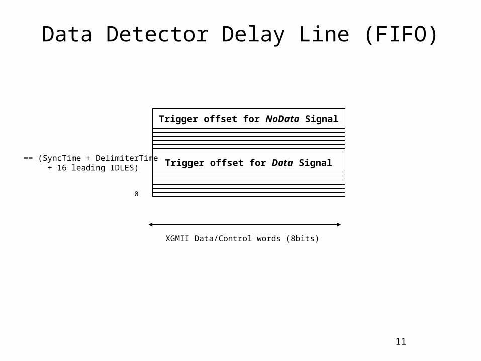
Data Detector Delay Line (FIFO)
XGMII Data/Control words (8bits)
Trigger offset for Data Signal
0
Trigger offset for NoData Signal
== (SyncTime + DelimiterTime + 16 leading IDLES)
12
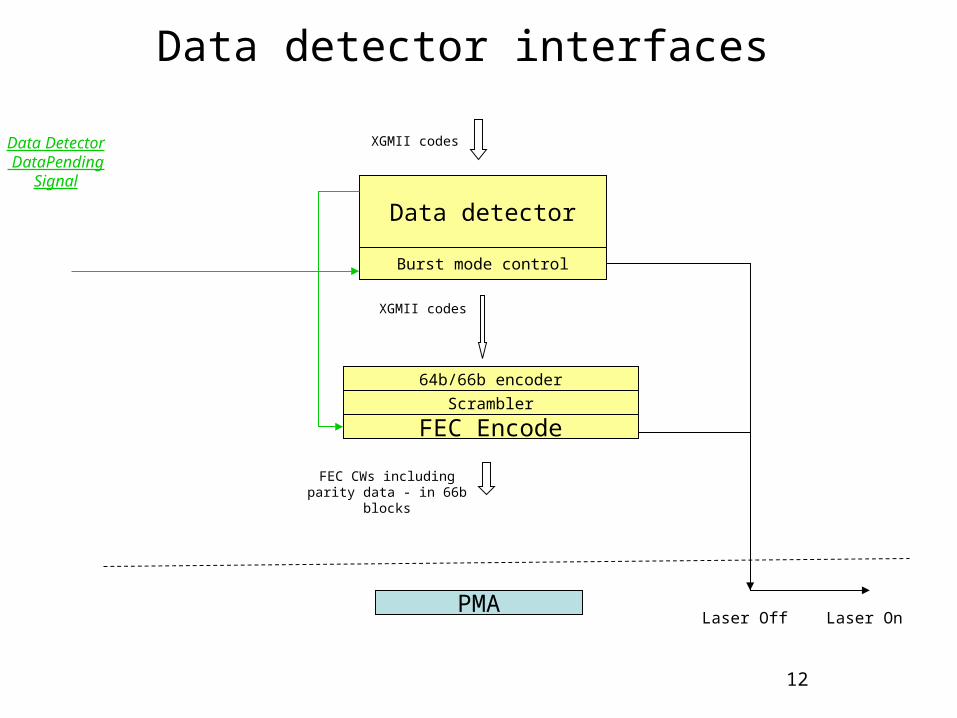
Data detector interfaces
Data detector
64b/66b encoder
FEC Encode
FEC CWs includingparity data - in 66b blocks
XGMII codes
Burst mode control
Scrambler
Data Detector DataPending
Signal
XGMII codes
Laser OnLaser OffPMA
13
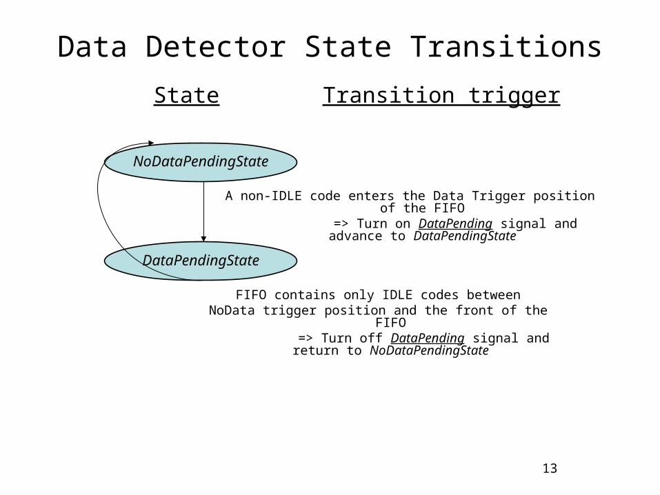
Data Detector State Transitions
NoDataPendingState
DataPendingState
State Transition trigger
FIFO contains only IDLE codes betweenNoData trigger position and the front of the FIFO
=> Turn off DataPending signal and return to NoDataPendingState
A non-IDLE code enters the Data Trigger position of the FIFO=> Turn on DataPending signal and advance to
DataPendingState
14
Data detector – laser on sequence
• Non-IDLE enters FIFO – causing Data Detector to raise the DataPending signal
• Burst Mode Control entity in CDRPhase state (see below) checks if DataPending signal is on and if so invokes PMD_Signal.Request(true)
15
Data detector – laser off sequence
• When FIFO contains only IDLEs, Data Detector resets the DataPending signal
• FEC Encoder checks the DataPending signal after each writing of parity words (see annex) and – if signal is false - invokes PMD_Signal.Request(false)
16
Burst Mode Locking sequence
17
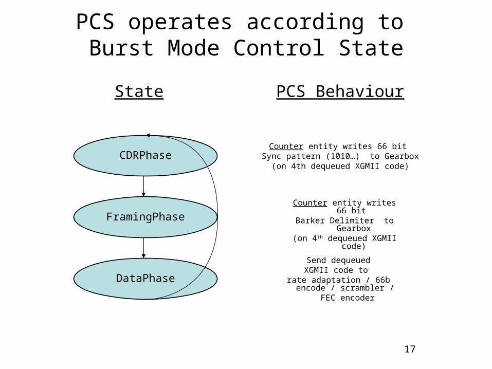
PCS operates according to Burst Mode Control State
Send dequeuedXGMII code to
rate adaptation / 66b encode / scrambler /
FEC encoder
Counter entity writes 66 bit Sync pattern (1010…) to Gearbox
(on 4th dequeued XGMII code)
Counter entity writes 66 bit Barker Delimiter to Gearbox
(on 4th dequeued XGMII code)
CDRPhase
FramingPhase
DataPhase
State PCS Behaviour
18
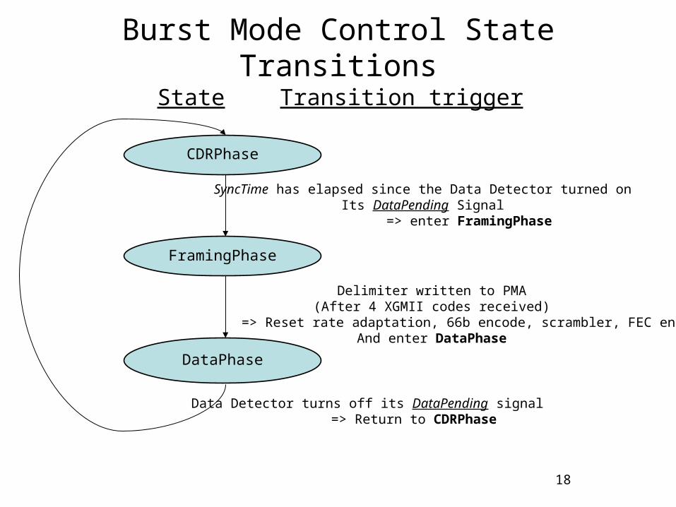
Burst Mode Control State Transitions
CDRPhase
FramingPhase
DataPhase
State Transition trigger
Data Detector turns off its DataPending signal=> Return to CDRPhase
Delimiter written to PMA(After 4 XGMII codes received)
=> Reset rate adaptation, 66b encode, scrambler, FEC encoderAnd enter DataPhase
SyncTime has elapsed since the Data Detector turned onIts DataPending Signal
=> enter FramingPhase
19
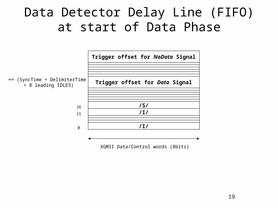
Data Detector Delay Line (FIFO)at start of Data Phase
XGMII Data/Control words (8bits)
Trigger offset for Data Signal
0
Trigger offset for NoData Signal
== (SyncTime + DelimiterTime + 8 leading IDLES)
/S/16
/I/15
/I/
20
Annex –Incorporating Rate Adaptation
21
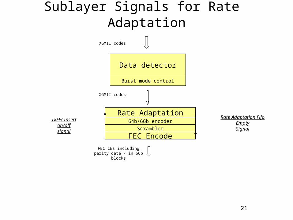
Sublayer Signals for Rate Adaptation
Data detector
64b/66b encoder
FEC Encode
FEC CWs includingparity data - in 66b blocks
XGMII codes
Burst mode control
Scrambler
Rate AdaptationTxFECInsert
on/offsignal
Rate Adaptation FifoEmptySignal
XGMII codes
22
Rate Adaptation Sublayer
• TxFECInsert On signal from FEC encoder tells sublayer to stop downward transmission of codes (so codes received from above accumulate at end of FIFO)
• TxFECInsert Off signal from FEC encoder tells sublayer to resume downward transmit of codes from front of FIFO (so arriving codes from above will be added to the end of the FIFO at the same rate that they clear from the front)
• When the buffer is non-empty, the sublayer deletes each arriving IDLE. The queued XGMII codes are concurrently dequeued from the front and transmitted to the 64b/66b encoder.
23
FEC encoder
• FEC encoder sends TxFECInsert On signal to Rate Adaptation sublayer when it is sending parity blocks.
• FEC encoder sends TxFECInsert Off signal to Rate Adaptation sublayer when it is ready to receive more 66b blocks.
• FEC encoder checks RateAdaptationFifoEmpty signal (in addition to DataPending) before turning off laser

24
Thank you