Framework for Design of Next-Generation Base-Isolated ... 1... · Framework for Design of...
24
Framework for Design of Next-Generation Base-Isolated Nuclear Facility Structures Bozidar Stojadinovic Professor, UC Berkeley Faculty Scientist, LBNL
Transcript of Framework for Design of Next-Generation Base-Isolated ... 1... · Framework for Design of...

Framework for Design of Next-Generation Base-Isolated Nuclear Facility Structures
Bozidar Stojadinovic
Professor, UC Berkeley
Faculty Scientist, LBNL

Next-Generation Nuclear Power Plants
Small Modular Reactors:
Less power, smaller size, smaller weight
Passively safe
Cooled by means other than water
Different fuel design:
Smaller source term
Compact fuel management
Proliferation-resistant
Easier to store/reprocess

Next-Generation Nuclear Power Plants
Economic case:
Build many essentially identical power plants
Enable a series of small investments
Fit the existing grid
Located at many more sites:
Higher hazard exposure
Different soil conditions

New Designs: Feature Seismic Isolation
Toshiba 4S GE PRISM

Seismic Isolation Concept

Dynamics of a Seismically Isolated System
Kelly, 1990

Period Elongation and Damping
Buckle, et.al, 2006

Seismic Isolator: Laminated Rubber Bearings
Technology developed in 1980’s
Used in buildings and but safety-critical structures:
LNG tanks
Hospitals
Emergency command centers
Considered for PRISM and SAFR

Seismic Isolator: Friction-Pendulum Bearings
Technology developed in 1990’s
Used in conventional building structures
Used in critical infrastructure:
San Francisco Bay Area long-span bridge crossings
Off-shore platforms

Seismic Isolator Behavior: Normal and Design Basis Loads
Buckle, et.al, 2006
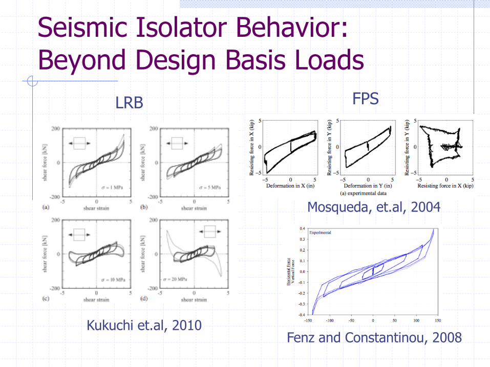
Seismic Isolator Behavior: Beyond Design Basis Loads
Fenz and Constantinou, 2008 Kukuchi et.al, 2010
Mosqueda, et.al, 2004
LRB FPS

Seismic Design Basis
NRC design basis:
Annual mean seismic CDF: 10-6
Annual mean FOSID: 10-5
ASCE 43-05, Section 1.3:
Given (modified) UHRS (MAF 10-4) design such that:
Less than 1% probability of unacceptable performance for the Design Basis Earthquake (DBE) ground motion
Less than 10% probability of unacceptable performance for a ground motion equal to 150% of the DBE ground motion

Unacceptable Performance: Isolated NPP
Target performance of the system:
ASCE 43-05: SDC 5D for SSCs
Isolated superstructure is expected to remain essentially elastic:
Reduced horizontal accelerations
Lesser of equal vertical accelerations
Smaller non-structural demands
Foundations are expected to remain elastic
Applies to all but the isolation system

Unacceptable Performance: Seismic Isolators
Exceeding horizontal deformation capacity
Rubber tearing in shear
FPS bearings hitting the rim
Exceeding vertical deformation capacity
Rubber tearing in tension
FPS bearing disassembling
Loss of stability in compression
Buckling
Roll-out
Failure of isolator attachments

Unacceptable Performance: Isolation System
Impact of the isolated structure:
Horizontally, against adjacent structures or surrounding soil
Vertically, due to uplift caused by:
Vertical excitation
Overturning/rocking
Resulting in high-frequency excitation of the isolated super-structure and its content

Unacceptable Performance: Isolation System
Local failure of the foundation or isolation diaphragms:
Excessive deformation leading to isolator deformation or load redistribution
Inability to redistribute loads in case of single isolator failure

Acceptance Criteria (ASCE 4) 1. Individual isolators shall suffer no damage in DBE
shaking
2. The probability of the isolated nuclear structure impacting surrounding structure is:
1% or less for DBE shaking
10% or less for 150% DBE shaking
3. Individual isolators shall sustain gravity and earthquake-induced axial loads at a displacement larger or equal to 90th percentile lateral displacements consistent with 150% DBE shaking
Whittaker and Huang, for ASCE 4

Satisfying Acceptance Criteria
Criteria 1: by isolation device design and production-testing of individual isolators
ASCE 4 adopts a standard test protocol
Criteria 2: by analysis, given a best-estimate isolator, structure and soil model as well as ground motion representation
ASCE 4 response amplification:
3x the median DBE response
Criteria 3: by prototype-testing of a limited number of isolators and by analysis
Whittaker and Huang, for ASCE 4

Role of SSI Analysis: Ground Motion Specification
Seismological aspects:
UHRS and record selection for response frequencies of interest:
Horizontal 0.2 to 0.5 Hz
Vertical 2 to 20 (or more) Hz
Effect of local soil response on horizontal and vertical excitation
Wave propagation:
Ground motion component coherency
Near-field effects
Rotation components (rolling)

Role of SSI Analysis: Local Soil Response
Foundation and soil deformability:
Short term, under extreme loads
Long term
Ability to transmit ground motion into the structure:
Foundation-soil interface
Static and dynamic stability of slopes:
Isolation moat
Structures partially or completely under ground
Soil and slope behavior under impact

Role of SSI Analysis: Interaction Itself
Interaction between the soil, foundation, seismic isolation, and the isolated structure:
Three-dimensional
Inherently non-linear
Integrated
Crucial for assessment of isolation system performance:
Seismic isolation needs better SSI

SSI Analysis Challenges
Integrated, non-linear time-domain modeling of the isolated structure and the surrounding soil
Include non-linear seismic isolator models
Verification and validation in the response ranges of interest
Speed and user interface suitable for production runs

Benefits of Seismic Isolation
Seismic isolation technology is mature and ready for NPP application
Reduces seismic risk:
Response is more predictable
Performance characteristics of SSCs in a seismically isolated NPP are better
Facilitates standardization:
Reduces cost and time to build
May simplify design and regulatory review

Thank you!
This work was performed under the auspices of the U.S. Department of Energy by the University of California, Lawrence Berkeley National Laboratory under Contract DE-AC02-05CH11231. This project, known at NRC as project #N6509, was supported by the U.S. Nuclear Regulatory Commission under a Federal Interagency Agreement with DOE.