FRACTUS ANTENNAS, S.L. · PDF fileFig. 3 Mobile product design cycle: the handset and the...
12
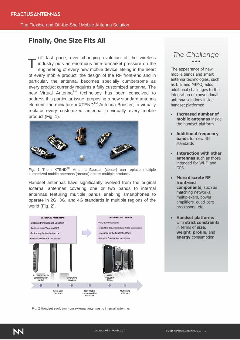
Last updated on March 2017 © 2016 FRACTUS ANTENNAS, S.L. - 1 The Flexible and Off-the-Shelf Mobile Antenna Solution The Challenge The appearance of new mobile bands and smart antenna technologies, such as LTE and MIMO, adds additional challenges to the integration of conventional antenna solutions inside handset platforms: Increased number of mobile antennas inside the handset platform Additional frequency bands for new 4G standards Interaction with other antennas such as those intended for Wi-Fi and GPS More discrete RF front-end components, such as matching networks, multiplexers, power amplifiers, quad-core processors, etc. Handset platforms with strict constraints in terms of size, weight, profile, and energy consumption Finally, One Size Fits All HE fast pace, ever changing evolution of the wireless industry puts an enormous time-to-market pressure on the engineering of every new mobile device. Being in the heart of every mobile product, the design of the RF front-end and in particular, the antenna, becomes specially cumbersome as every product currently requires a fully customized antenna. The new Virtual Antenna TM technology has been conceived to address this particular issue, proposing a new standard antenna element, the miniature mXTEND TM Antenna Booster, to virtually replace every customized antenna in virtually every mobile product (Fig. 1). Fig. 1 The mXTEND TM Antenna Booster (center) can replace multiple customized mobile antennas (around) across multiple products. Handset antennas have significantly evolved from the original external antennas covering one or two bands to internal antennas featuring multiple bands enabling smartphones to operate in 2G, 3G, and 4G standards in multiple regions of the world (Fig. 2). EXTERNAL ANTENNAS •Single and/or Dual Band Operation •Basic services: Voice and SMS •Protruding the handset phone •Limited mechanical robustness INTERNAL ANTENNAS •Multi-Band Operation •Innovative services such as Video Conference •Integrated in the handset platform •Aesthetic /Mechanical robustness Success in mobile communication market Great user demands Innovative services New mobile communication standards Wide Frequency Range Multi-band antennas T Fig. 2 Handset evolution from external antennas to internal antennas
Transcript of FRACTUS ANTENNAS, S.L. · PDF fileFig. 3 Mobile product design cycle: the handset and the...
Last updated on March 2017 © 2016 FRACTUS ANTENNAS, S.L. - 1
The Flexible and Off-the-Shelf Mobile Antenna Solution
The Challenge
The appearance of new
mobile bands and smart
antenna technologies, such
as LTE and MIMO, adds
additional challenges to the
integration of conventional
antenna solutions inside
handset platforms:
Increased number of
mobile antennas inside
the handset platform
Additional frequency
bands for new 4G
standards
Interaction with other
antennas such as those
intended for Wi-Fi and GPS
More discrete RF
front-end
components, such as matching networks,
multiplexers, power
amplifiers, quad-core processors, etc.
Handset platforms
with strict constraints in terms of size,
weight, profile, and
energy consumption
Finally, One Size Fits All
HE fast pace, ever changing evolution of the wireless
industry puts an enormous time-to-market pressure on the
engineering of every new mobile device. Being in the heart
of every mobile product, the design of the RF front-end and in
particular, the antenna, becomes specially cumbersome as
every product currently requires a fully customized antenna. The
new Virtual AntennaTM technology has been conceived to
address this particular issue, proposing a new standard antenna
element, the miniature mXTENDTM Antenna Booster, to virtually
replace every customized antenna in virtually every mobile
product (Fig. 1).
Fig. 1 The mXTEND
TM Antenna Booster (center) can replace multiple
customized mobile antennas (around) across multiple products.
Handset antennas have significantly evolved from the original
external antennas covering one or two bands to internal
antennas featuring multiple bands enabling smartphones to
operate in 2G, 3G, and 4G standards in multiple regions of the
world (Fig. 2).
EXTERNAL ANTENNAS
•Single and/or Dual Band Operation
•Basic services: Voice and SMS
•Protruding the handset phone
•Limited mechanical robustness
INTERNAL ANTENNAS
•Multi-Band Operation
•Innovative services such as Video Conference
•Integrated in the handset platform
•Aesthetic /Mechanical robustness
Success in mobile communication
market
Great user demands
Innovative services
New mobile communication
standards
Wide Frequency
Range
Multi-band antennas
T
Fig. 2 Handset evolution from external antennas to internal antennas

Last updated on March 2017 © 2016 FRACTUS ANTENNAS, S.L. - 2
The Flexible and Off-the-Shelf Mobile Antenna Solution
Advantages
Off-the-Shelf
No customization is
required. The proposed
solution can be
standardized across
multiple devices and
platforms, thus
providing faster time-to-
market and lower cost,
instead of design,
development, and
industrialization
dependent efforts
Reduced Size
The mXTENDTM Antenna
Booster is a 5 mm cube.
Its size is around an
order of magnitude less
(1/10) in volume than
current state of the art
handset antennas (Fig.
1 and Fig. 4)
Multiband
A simple way to operate
not only current mobile
bands but also to
upgrade the bands for
cellular platforms to LTE
and follow-up
generations
Advantages
Flexible
Modular and adaptive
design since the same
product can be used to
cover different
frequency regions
Versatility and scalability
Easily adaptable to the
customers’ needs. The
customer can elect the
operating frequency
bands without requiring
the customization of the
product
Passive
Completely passive,
thus preserving the
duration of the battery
Simplicity
Simplifies handset Front
End Modules (FEMs)
complexity
Pick and Place
Simplifies assembly
process and increase
production rates
The market pressure is currently focused on demanding handset
devices capable of supporting sophisticated services requiring
considerable high quality, high data rates, such as video on
demand, video streaming, video conference, voice over IP, etc.
The integration of all these services and functionalities inside
current handset platforms featured by strict constraints in terms of
size, weight, profile, and energy consumption increases the
challenges for antenna engineers.
Following the state-of-the-art approach in handset antenna
design, the complexity of the antenna solution increases together
with an increase in the number of operating frequency bands.
Generally, the larger the number of operating bands the greater
the dimensions of the antenna and its geometrical complexity.
The current technological trend has been precisely to take
advantage of geometrical complexity to optimize the size and
performance of every antenna in every single mobile device [1]-
[2]. In general terms, the greater the number of bands, the greater
antenna complexity to pack all radio wavelengths in the available
space inside the mobile platform.
Fig. 3 Mobile product design cycle: the handset and the antenna are co-engineered in a cumbersome iterative process.
Concept Integration Production
Co
nc
ep
t &
pre
lim
ina
ry d
es
ign
De
ve
lop
me
nt
Op
tim
isa
tio
n &
Inte
gra
tio
n
Ind
us
tria
lis
ati
on
Ha
rd T
oo
l g
o
Qu
ali
fic
ati
on
Ra
mp
up
Ma
ss
pro
du
cti
on
Pro
du
ct
up
gra
de
Ma
rketi
ng
&
sa
les
From Antenna Concept to Final Product
Current mobile platforms integrate a
customized antenna design in each handset
product. This considerably increases the
complexity in all the stages that form the
product design cycle. This results a slow
down of the time-to-market while increasing
both design and manufacturing costs

Last updated on March 2017 © 2016 FRACTUS ANTENNAS, S.L. - 3
The Flexible and Off-the-Shelf Mobile Antenna Solution
Such a design approach is subject to the well-known physical limit in the performance of
small antennas [3]. A well-known fundamental principle in antenna design is that an antenna
must keep a minimum size relative to the longest operating wavelength to radiate efficiently.
Beyond a certain size limit, a further antenna reduction results in a rapidly decreasing
bandwidth and efficiency. It is known that an antenna enters into the ‘small antenna’ regime
when its overall size is smaller than /. In a mobile system and considering a longest
operating wavelength at a frequency of 824 MHz, such a limit is around 120mm, right about
twice the top edge of a mobile phone where the antenna is usually located. Following this
thought, this means that about every modern mobile phone antenna, even those integrated
in current large smartphones, operates well within the small antenna regime and it is
therefore understood to be subject to the bandwidth and efficiency constraints of small
antennas. In other words, to further reduce the antenna size an antenna engineer needs to
face overcoming a fundamental wall that has constrained antenna evolution for decades.
Besides those fundamental limits, other practical constraints introduce additional hurdles
when integrating an antenna into a mobile platform. For instance, the performance of a
handset antenna solution is strongly conditioned by the architecture of the handset platform
and the components integrated thereof, such as battery, display, shieldings, covers, and
alike. When customizing the antenna inside the phone, the antenna engineer needs to bear
in mind not only the bands, bandwidth, size, and efficiency constraints inherent to the design
of every antenna, but the co-existence of all those neighboring elements that might interact
with antenna near fields. This results in an iterative design, integration, and optimization
processes, which supposes a time-consuming and costly approach (Fig. 3).
Fig. 4 Fifteen years of handset antenna evolution. A first dual-band internal antenna (left) obtained by grouping two antennas into a conjoined antenna set (year 1999); a state-of-the-art antenna (center) taking benefit of complexity to optimize the packaging of five frequency bands (year 2011); the mXTEND
TM Antenna Booster
replacing both (right) (year 2013).
Last updated on March 2017 © 2016 FRACTUS ANTENNAS, S.L. - 4
The Flexible and Off-the-Shelf Mobile Antenna Solution
The Virtual AntennaTM solution aims to throw some light into this landscape by simplifying the
design process while reducing the time-to-market and cost of the final mobile product.
Fractus Antennas solution based on the mXTENDTM antenna booster is capable of replacing
conventional handset antennas of large dimensions by miniature and off-the-shelf, standard
mobile antenna components. The solution can be effectively standardized across multiple
handsets sharing the same platform while featuring different form factors. The proposal has
been specially thought to simplify the migration process from 3G to 4G, and it becomes a
radical step forward in the evolution of handset engineering (Fig.4).
Virtual Antenna
TM Technology
The proposed Virtual AntennaTM
technology breaks away from the
original way of designing handset
antennas. Typically, mobile antenna
solutions are designed in such a way
that a single antenna element is
intended to provide multiband
performance. It means that multiple
operating wavelengths must be
packed into this single element, thus
leading to complex antenna
geometries and considerable
dimensions. The complexity of these solutions increases together with the increasing number
of operating frequency bands and the decreasing size of the antenna element. How come
Fractus’ antenna booster, featuring a size which is typically x10 times smaller than a
customized antenna can replace current state-of-
the-art technology? A key aspect of the technology
relies on optimizing the radiation commonly obtained
through the ground plane and other conductive
elements already inherent in any handset platform.
Thanks to this optimization the size of the antenna
elements can be significantly reduced while obtaining
a suitable electromagnetic performance for a wide
range of wireless device platforms [4]-[20].
Current handset antenna solutions are commonly
connected to a Front End Module (FEM) through a
single input/output port. This fact increases the
matching network and FEM complexity. In particular,
more sophisticated matching networks, filtering, and
power amplifier stages are required to split and process each frequency band separately,
which increases the complexity, losses, and costs of the overall system. In addition, the
Printed Circuit Board (PCB) space is becoming one of the most precious and contested real
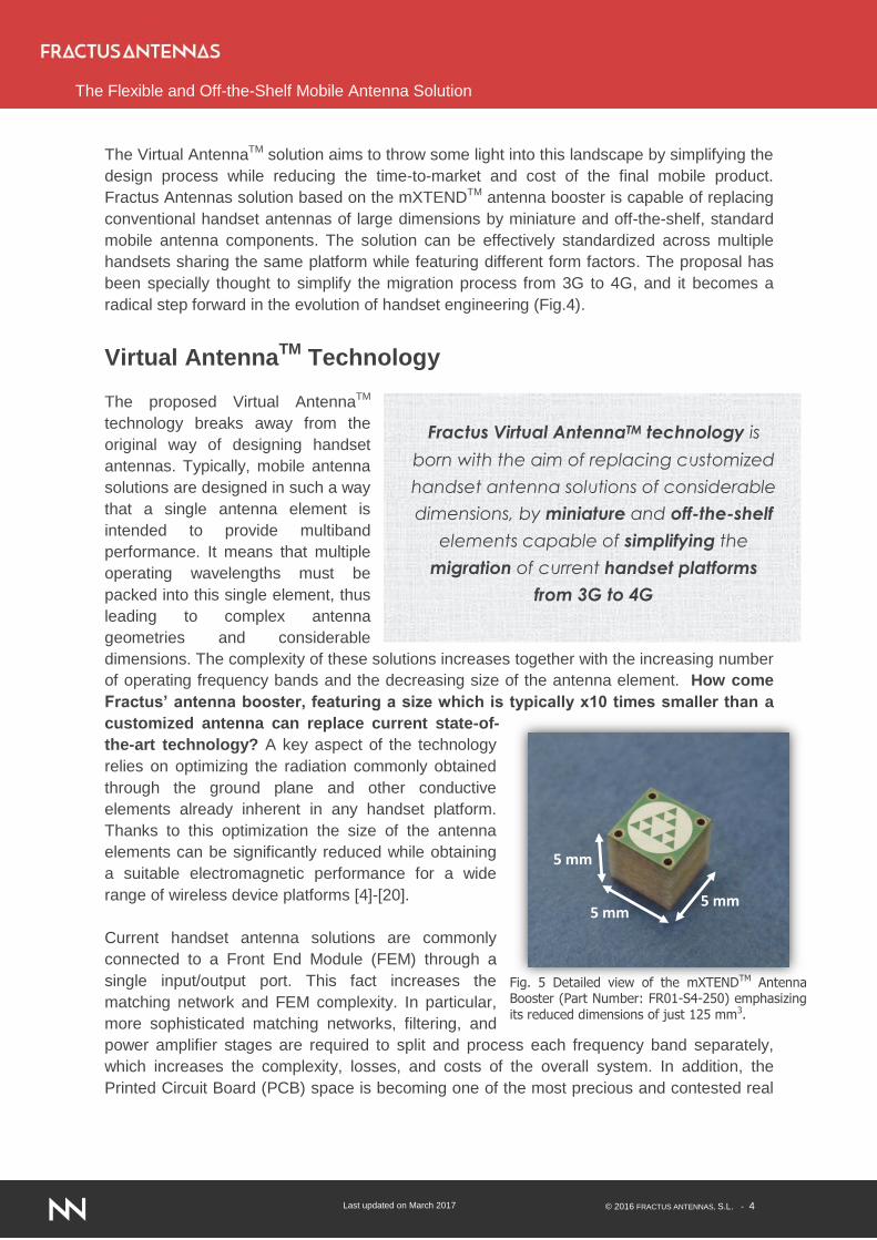
5 mm5 mm
5 mm
Fig. 5 Detailed view of the mXTENDTM Antenna Booster (Part Number: FR01-S4-250) emphasizing its reduced dimensions of just 125 mm3.
Fractus Virtual AntennaTM technology is
born with the aim of replacing customized
handset antenna solutions of considerable
dimensions, by miniature and off-the-shelf
elements capable of simplifying the
migration of current handset platforms
from 3G to 4G
Last updated on March 2017 © 2016 FRACTUS ANTENNAS, S.L. - 5
The Flexible and Off-the-Shelf Mobile Antenna Solution
state in the mobile landscape of nowadays. Therefore, any solution capable of minimizing the
required PCB space while simplifying the electronics becomes attractive. The Virtual
AntennaTM technology combines one or more mXTENDTM antenna boosters with one or more
specifically designed matching network to provide multi-port or single port antenna front-end
that seamlessly matches the RF circuitry of the mobile front-end.
mXTEND
TM Antenna Booster
The mXTENDTM Antenna Booster is a miniature and standard product specially designed to
provide operation in mobile bands. It is a surface-mount device (SMD) that can be directly
placed onto the PCB trough pick and place machines [11]. The use of SMD technology and
pick and place machines directly leads to significant advantages in terms of manufacturing
and costs. The size of the mXTENDTM Antenna Booster has been reduced in an order of
magnitude (x10) with respect to other current state of the art solutions (Fig. 5). The product is
not only capable of operating current mobile bands (GSM850, GSM900, GSM1800,
GSM1900, and UMTS…), but also to upgrade the bands to LTE and follow-up generations
(LTE700, LTE2100, LTE2300,
LTE2500...).
Evaluation Board
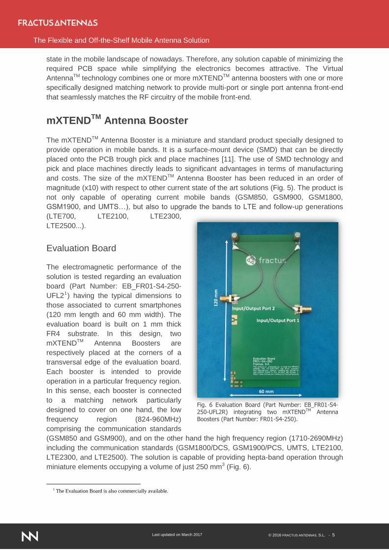
The electromagnetic performance of the
solution is tested regarding an evaluation
board (Part Number: EB_FR01-S4-250-
UFL21) having the typical dimensions to
those associated to current smartphones
(120 mm length and 60 mm width). The
evaluation board is built on 1 mm thick
FR4 substrate. In this design, two
mXTENDTM Antenna Boosters are
respectively placed at the corners of a
transversal edge of the evaluation board.
Each booster is intended to provide
operation in a particular frequency region.
In this sense, each booster is connected
to a matching network particularly
designed to cover on one hand, the low
frequency region (824-960MHz)
comprising the communication standards
(GSM850 and GSM900), and on the other hand the high frequency region (1710-2690MHz)
including the communication standards (GSM1800/DCS, GSM1900/PCS, UMTS, LTE2100,
LTE2300, and LTE2500). The solution is capable of providing hepta-band operation through
miniature elements occupying a volume of just 250 mm3 (Fig. 6).
1 The Evaluation Board is also commercially available.
12
0 m
m
60 mm
Input/Output Port 2
Input/Output Port 1
Fig. 6 Evaluation Board (Part Number: EB_FR01-S4-250-UFL2R) integrating two mXTENDTM Antenna Boosters (Part Number: FR01-S4-250).

Last updated on March 2017 © 2016 FRACTUS ANTENNAS, S.L. - 6
The Flexible and Off-the-Shelf Mobile Antenna Solution
Matching Network
The matching network for the low
frequency region comprises a
series inductor, a broadband
mechanism [4]-[5], [12]-[13], [21]
comprising a parallel resonator,
and a fine tuning stage formed
by a series capacitor (Fig. 7). On
the other hand, the matching
network for the high frequency
region consists in a “T” matching
network comprising a series
inductor, a shunt inductor, and a
series capacitor2 (Fig. 8). In this
case, the evaluation board further
includes two UFL 3 cables to
connect each mXTENDTM
Antenna Booster to each SMA
connector. Thus, a two port
solution is obtained (Fig. 6).
One of the advantages of this
two port solution with respect to
current single input/output port
designs mainly relies on the simplification of the matching network and the Front End Module
(FEM). In this solution, no additional matching network or filtering stages are required to
merge a two input/output port solution into a single port solution. Accordingly, the number of
reactive elements required is minimized, and with them, complexity and ohmic losses.
Furthermore, since the two operating regions, low and high frequency region, are not merged
into a single input/output port, there is no need to split them with multiplexers. In this way, the
number of filtering stages in the FEM is
also reduced and consequently, losses
and complexity are again minimized.
Nevertheless and with the aim of
providing adaptive solutions to each
customer needs, Fractus also provides a
merged solution for those designs
requiring a single input/output port.
Further to the previous matching network
components, this merged solution
includes a diplexer [12]-[13].
2 High Quality Factor (Q), tight tolerance components are recommended for an optimum performance. 3 The UFL cables can be replaced by other transmission line technology, (coplanar, microstrip, etc.) according to the customer needs.
mXTENDTM
Fig. 8 Matching network for the high frequency region (1710-2690MHz). The components are SMD 0402 commercially available.
mXTENDTM
Fig. 7 Matching network designed to cover the low frequency region (824-960MHz). The components are SMD 0402 commercially available.
Flexibility in choosing the operating
frequencies: from single band up to hepta-
band operation without requiring the
customization of the mXTENDTM Antenna
Booster, just a matching network
adjustment
Last updated on March 2017 © 2016 FRACTUS ANTENNAS, S.L. - 7
The Flexible and Off-the-Shelf Mobile Antenna Solution
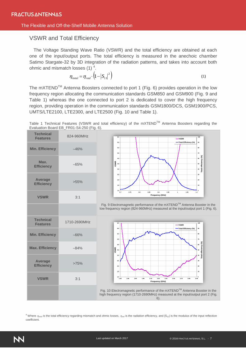
VSWR and Total Efficiency
The Voltage Standing Wave Ratio (VSWR) and the total efficiency are obtained at each
one of the input/output ports. The total efficiency is measured in the anechoic chamber
Satimo Stargate-32 by 3D integration of the radiation patterns, and takes into account both
ohmic and mismatch losses (1) 4.
2
111 Sradtotal (1)
The mXTENDTM Antenna Boosters connected to port 1 (Fig. 6) provides operation in the low
frequency region allocating the communication standards GSM850 and GSM900 (Fig. 9 and
Table 1) whereas the one connected to port 2 is dedicated to cover the high frequency
region, providing operation in the communication standards GSM1800/DCS, GSM1900/PCS,
UMTS/LTE2100, LTE2300, and LTE2500 (Fig. 10 and Table 1).
Table 1 Technical Features (VSWR and total efficiency) of the mXTEND
TM Antenna Boosters regarding the
Evaluation Board EB_FR01-S4-250 (Fig. 6).
Technical Features
824-960MHz
Fig. 9 Electromagnetic performance of the mXTEND
TM Antenna Booster in the
low frequency region (824-960MHz) measured at the input/output port 1 (Fig. 6).
Min. Efficiency
46%
Max.
Efficiency
65%
Average
Efficiency
>55%
VSWR
3:1
Technical Features
1710-2690MHz
Fig. 10 Electromagnetic performance of the mXTEND
TM Antenna Booster in the
high frequency region (1710-2690MHz) measured at the input/output port 2 (Fig. 6).
Min. Efficiency
66%
Max. Efficiency
84%
Average
Efficiency
>75%
VSWR
3:1
0
10
20
30
40
50
60
70
80
90
100
1.0
1.5
2.0
2.5
3.0
3.5
4.0
4.5
5.0
5.5
6.0
0.7 0.75 0.8 0.85 0.9 0.95 1 1.05 1.1
To
tal eff
icie
ncy (
%)
VS
WR
Frequency (GHz)
VSWR
Total Efficiency (%)
0
10
20
30
40
50
60
70
80
90
100
1.0
1.5
2.0
2.5
3.0
3.5
4.0
4.5
5.0
5.5
6.0
1.50 1.65 1.80 1.95 2.10 2.25 2.40 2.55 2.70 2.85 3.00
To
tal eff
icie
ncy (
%)
VS
WR
Frequency (GHz)
VSWR
Total Efficiency (%)
4 Where total is the total efficiency regarding mismatch and ohmic losses, rad is the radiation efficiency, and |S11| is the modulus of the input reflection
coefficient.

Last updated on March 2017 © 2016 FRACTUS ANTENNAS, S.L. - 8
The Flexible and Off-the-Shelf Mobile Antenna Solution
Radiation Patterns and Specific Absorption Rate (SAR)
The main cuts of the radiation patterns (phi=0º, phi=90º, and theta=90º) as well as their 3D
plots, are measured at main frequencies of the low and high frequency region (Table 2). The
results illustrate the omnidirectional properties of the solution. More particularly, the radiation
pattern in the low frequency region presents an omnidirectional cut in the phi=0º plane and a
minimum in the direction of the longitudinal axis (y axis), as typical in handsets. These
omnidirectional properties make the solution suitable for mobile communications.
Table 2 Technical features, main cuts, and 3D representation of the radiation patterns (Dynamic range: 30dBs).
Fig. 11 Measurement set-up in the anechoic chamber Satimo Stargate-32.
Phi=0º (890MHz)
Phi=90º (890MHz)
Theta=90º (890MHz)
Phi=0º
Phi=90º
Technical Features
824-960MHz
1710-
2690MHz
Min. Gain -0.4 dBi 1.8 dBi
Max. Gain 1.4 dBi 3.6 dBi
Average Gain 0.5 dBi 2.6 dBi
Radiation Patterns
Omnidirectional
Polarizaton Linear
Weight 0.25 g
Temperature -40º C to +85º C
Impedance 50
Dimensions 5.0 mm x 5.0 mm x 5.0 mm
Minimum isolation
between port 1 and port 2
31dBs (at aproximately 935MHz)
Theta=0º
XY
Z
θ
12
0 m
m
60 mm
Input/Output Port 2
Input/Output Port 1
X
Y
Z
y
x
z
y
x
z
Last updated on March 2017 © 2016 FRACTUS ANTENNAS, S.L. - 9
The Flexible and Off-the-Shelf Mobile Antenna Solution
The biological compatibility and user interaction of Fractus antenna boosters is described in
[14]-[15]. Results show that SAR values below the standards (American standard
(ANSI/IEEE): 1.6mW/g (1g) and European standard (ICNIRP) 2mW/g (10g)) can be obtained
and that those become particularly low when the boosters are placed in the lower edge of the
PCB. Additionally, the dual booster arrangement provides intrinsec robustness against finger
detuning effect since the blocking of one of the boosters has negligible impact on the
performance of the other one [10], [18].
Mobile Connectivity Made Simpler
Fractus Virtual AntennaTM technology has been conceived to make the design of mobile
products simpler, faster, and cost-effective. By using a modular solution based on a first
antenna booster product, the mXTENDTM product, mobile device OEMs benefit from:
Solving the size limitations of current handset technologies while preserving the
electromagnetic performance of the device.
Reducing the size of the antenna component by a ten times factor. The
dimensions of the mXTENDTM
Antenna Booster, a cube of just 5 mm on the side, is
an order of magnitude smaller than other current state of the art handset antennas,
while offering the required electromagnetic performance.
Scaling their product range to emerging technology trends such as MIMO. The
considerable reduced size of the mXTENDTM
Antenna Booster makes the solution
particularly suitable for embeding multiple antenna elements into a single device.
The new Virtual AntennaTM
technology further provides modular and adaptive
designs to the customers’ needs. It offers enough flexibility as to choose between
single-band up to hepta-band operation without requiring the customization of the
product. It means that the same mXTENDTM
booster can be used to provide operation
at different mobile frequency bands ranging from 824-960MHz and 1710-2690MHz.
From the commercial perspective, the solution not only simplifies design processes
but also manufacturing costs, since it can be standardized across multiple devices
and platforms as it is an off-the-shelf solution.
In summary, the new Virtual AntennaTM technology released by Fractus Antennas becomes
an alternative to the traditional customized antenna technology and appears as standardizing
solution for current and future multifunctional wireless devices.

Last updated on March 2017 © 2016 FRACTUS ANTENNAS, S.L. - 10
The Flexible and Off-the-Shelf Mobile Antenna Solution
About Fractus Antennas
Fractus Antennas SL designs, manufactures and commercializes miniature, off-the-shelf
antennas for smartphones, and wirelessly connected IoT devices. Founded as an
independent antenna product business in 2015, Fractus Antennas was born out of the main
Fractus operation and combines a cutting-edge R&D team with proven manufacturing
capabilities and scale to bring to market a new generation of antenna products to meet the
mobile and wireless connectivity needs of OEMs.
From the team that pioneered fractal antennas in the 1990’s Fractus Antennas is releasing a
new antenna technology generation with its Virtual AntennaTM products. Fractus Antennas’
Virtual AntennaTM solution provides a way to upgrade the bands for cellular platforms to LTE
and follow-up generations by means of an ultra-compact antenna solution that can be
standardized across multiple devices and platforms. Such a full-passive, off-the-shelf solution
provides an ‘always on’ connectivity to smartphones and mobile/IoT devices so that
advanced techniques such as inter-band carrier aggregation can be seamlessly implemented
into a mobile device.
Fractus Antennas team is an early pioneer in developing internal antennas for cellular
phones and related handheld wireless devices. In 1995, Fractus Antennas’ lead scientist filed
the world’s first patent application on fractal antennas for mobile telecommunications.
Nowadays, Fractus Antennas’
products have been shipped to over
1.000 OEMs worldwide and
embedded into over 50 million mobile
and wireless devices, including
smartphones, mobile handsets,
portable navigation devices, game
consoles, laptops/netbooks, tablets
and e-reader
Fractus Antennas holds an
Intellectual Property Rights portfolio
of more than 20 patent families, 40
patents and patent applications
including 15 granted patents, related
to its proprietary Virtual Antenna Technology, This patent portfolio reaches several of the
main world markets including the US, Europe and China. Among the numerous awards and
honors its team has received for its innovative work, they were named Technology Pioneer
by the Davos World Economic in 2005, and nominated to the European Inventor Award in
2014.
Fig. 12 Fractus Antennas’ laboratory.
Last updated on March 2017 © 2016 FRACTUS ANTENNAS, S.L. - 11
The Flexible and Off-the-Shelf Mobile Antenna Solution
References
[1] C. Puente, J. Romeu, C. Borja, J. Anguera, “Multilevel Antennae”, International
Publication Number WO01/22528.
[2] C. Puente, E. Rozan, J. Anguera, “Space-Filling Miniature Antennas”, International
Publication Number WO01/54225.
[3] J. S. McLean, “A re-examination of the fundamental limits on the radiation Q of
electrically small antennas,” IEEE Transactions on Antennas and Propagation, vol.
AP-44, pp. 672–676, May 1996.
[4] J. Anguera, A. Andújar, C. Puente, J. Mumbru, “Antennaless Wireless Device”, Patent
Number US8203492.
[5] J. Anguera, A. Andújar, C. Puente, J. Mumbru, “Antennaless Wireless Device
Capable of Operation in Multiple Frequency Regions”, Patent Number US8237615.
[6] J. Anguera and A. Andújar, "Antennaless Wireless Device comprising One or More
Bodies", International Publication Number WO2011095330A1.
[7] A. Andújar, J. Anguera, C. Puente, and C. Picher, "Wireless Device capable of Multi-
band MIMO Operation" International Publication Number WO2012017013A1.
[8] A. Andújar and J. Anguera, "Compact Radiating Array for Wireless Handheld or
Portable Devices", Patent Application Number US 61/661,885.
[9] J. Anguera, C. Picher, A. Andújar, and C. Puente, "Concentrated Antennaless
Wireless Device providing Operability in Multiple Frequency Regions", Patent
Application Number US 61/671,906.
[10] A. Andújar and J. Anguera, "Scattered Virtual Antenna Technology for Wireless
Devices", Patent Application Number US 61/837,265.
[11] J. Anguera, A. Andújar, and C. Puente, "Wireless Handheld Devices, Radiation
Systems, and Manufacturing Methods", Patent Application Number US 13/946,922.
[12] A. Andújar, J. Anguera, and C. Puente, "Ground Plane Boosters as a Compact
Antenna Technology for Wireless Handheld Devices", IEEE Transactions on
Antennas and Propagation, vol. 59, nº 5, May 2011, pp. 1668-1677.
[13] A. Andújar, J. Anguera, and C. Puente, "Ground Plane Boosters to provide Multi-
Band Operation in Wireless Handheld Devices", Proceedings of the Fifth European
Conference on Antennas and Propagation, EuCAP 2011, Rome, Italy, April 2011, pp.
599-603.
[14] A. Andújar, J. Anguera, C. Picher, and C. Puente, "Human Head Interaction over
Ground Plane Booster Antenna Technology: Functional and Biological Analysis",
Progress in Electromagnetic Research B, vol. 41, 2012, pp. 153-185.
[15] A. Andújar, J. Anguera, C. Picher, and C. Puente, "Ground Plane Booster Antenna
Technology. Human Head Interaction: Functional and Biological Analysis",
Proceedings of the Sixth European Conference on Antennas and Propagation,
EuCAP 2012, Prague, Czech Republic, March 2012, pp. 2745-2749.
[16] A. Andújar and J. Anguera, "On the Radio-Frequency System of Ground Plane
Booster Antenna Technology", IEE Electronics Letters, vol. 48, nº 14, July 2012, pp.
815-817.

Last updated on March 2017 © 2016 FRACTUS ANTENNAS, S.L. - 12
The Flexible and Off-the-Shelf Mobile Antenna Solution
[17] J. Anguera, A. Andújar, M. Huynh, C. Orlenius, C. Picher, and C. Puente, "Advances
in Antenna Technology for Wireless Handheld Devices", International Journal on
Antennas and Propagation, Volume 2013, ID 838364.
[18] A. Andújar, J. Anguera, and Y. Cobo, "Distributed Systems Robust to Hand Loading
based on Non-Resonant Elements", Microwave and Optical Technology Letters,
vol.55, nº10, October 2013, pp-2307-2317.
[19] A. Andújar and J. Anguera, "Non-Resonant Elements with a Simplified
Radiofrequency System for Handset Devices", Proceedings of the Seventh European
Conference on Antennas and Propagation , EUCAP 2013, Gothenburg, Sweden,
April 2013.
[20] J. Anguera, C. Picher, A. Andújar, S. Kahng, and C. Puente, "Compact Multiband
Antenna System for Smartphone Platforms", Proceedings of the Seventh European
Conference on Antennas and Propagation , EUCAP 2013, Gothenburg, Sweden,
April 2013.
[21] A. Andújar, J. Anguera, and C. Puente, "A Systematic Method to Design Broadband
matching Networks", Proceedings of the Fourth European Conference on Antennas
and Propagation, EuCAP 2010, Barcelona, Spain, April 2010, pp. 1-5.
Authors: Dr. Aurora Andújar (R&D Manager), Dr. Carles Puente (Chief Scientist), Dr. Jaume
Anguera (R&D Manager), Adrià Dasquens (Product Manager Engineer), Yolanda Cobo (Lab
Engineer), Josep Portabella (Director Product & Services).