Fracture Parameters of Steel Fibre Reinforced High ... · The test results showed that the ... of...
6
International Journal of Scientific & Engineering Research, Volume 4, Issue 5, May 2013 ISSN 2229-5518 IJSER © 2013 http://www.ijser.org Abstract— This paper presents an experimental investigation on the fracture behaviour of high strength concrete and steel fibre reinforced high strength concrete with particular emphasis on the size effect method. Fracture study was carried out by conducting three point bending tests on series of geometrically similar single edge notched beams. The influence of notch size on the fracture properties of steel fibre reinforced high strength concrete was also investigated. Various fracture parameters like the fracture energy, length of fracture process zone, critical crack tip opening displacement and the fracture toughness were determined as per RILEM procedure. The test results showed that the fracture parameters are sensitive to the fibre addition and the notch size. With the experimental parameters an attempt has been made to predict the nominal strength of steel fibre reinforced high strength concrete structures. Index Terms- Concrete fracture ,Crack tip opening displacement ,Fracture energy, Fracture process zone, Fracture toughness ,Stress intensity factor, Size effect method ,Steel fibre reinforced high strength concrete.. 1. INTRODUCTION LTHOUGH concrete is often considered as a brittle material, it is actually a quasi-brittle material. Quasi-brittle materials are incapable of purely plastic deformation and in normal use have a fracture process zone (FPZ) which is not negligible compared to the structure size. Because of the inherent heterogeneity in the microstructure of concrete that leads to significant micro cracking under tension, a large process zone with strain stiffening behaviour is often formed before the unstable propagation of a major crack. As a result, fracture mechanics principles are only applicable to large scale initially cracked concrete structures. Design of concrete structures will benefit significantly from fracture mechanics. It will make it possible to achieve more uniform safety factors which will improve economy and reliability. This is apparent in large size structures, vessels or containments which behave in a rather brittle manner and the consequences of a potential failure are enormous. The experimentally observed size effect of structures can be adequately explained by fracture mechanics. According to the size effect law (SEL) the ultimate stress for geometrically similar structures of different sizes depends on the size of the structure [1]. The dependence of strength with respect to the size of specimen is more pronounced in structures made of cementitious materials due to their large FPZ _____________________________________ K.S. Prebhakumari, Asst. Professor, Dept. of Civil Engg. College of Engineering Trivandrum, India. PH-9447254798. E-mail: [email protected] P. Jayakumar, Assistant Executive Engineer, KWA, Trivandrum, India PH-9446340693. E-mail: [email protected] Classical theories, such as elastic analysis with allowable stress or plastic limit analysis cannot take into consideration the size effect. On the other hand, linear elastic fracture mechanics (LEFM) exhibits a strong size effect dependence described by the dependence of stress intensity factor (SIF) on the crack length [2]. A deterministic size effect exists in the strength of cracked concrete structures owing to the stress redistribution introduced by the presence of cracks manifested in the FPZ [3]. Usually many structures are designed to carry service loads that are high enough to initiate cracks, particularly when pre-existing flaws or stress concentrations are present, such structures can have only a limited life time and the probability of failure will be at a low level during the whole service life. The initiation and growth of large cracking zones up to a critical point of instability at the maximum load leads to the failure of concrete structures. In order to ensure the safety it has to be predicted how fast cracks will grow and how fast the residual strength will decrease. Fracture mechanics design methodology is based on the realistic assumption that, materials contain initial defects that can affect the load-carrying capacity of engineering structures. Defects may be initiated in the material by manufacturing procedures or can be created during the service life, by fatigue, environmental effects or creep. The analysis of the component is carried out with a crack placed in the most probable or dangerous location and determining a characteristic quantity defining the possibility of the crack to extend. The characteristic quantity depends on the particular failure criterion used, and in the case of fracture analysis, it is the stress intensity factor, K I equal to the K Ic . By this way it is possible to determine the maximum allowable applied loads for a specified crack size, or the maximum permissible crack size for specified applied loads. K.S. Prebhakumari, P. Jayakumar Fracture Parameters of Steel Fibre Reinforced High Strength Concrete by Size Effect Method A 254 IJSER
Transcript of Fracture Parameters of Steel Fibre Reinforced High ... · The test results showed that the ... of...

International Journal of Scientific & Engineering Research, Volume 4, Issue 5, May 2013 ISSN 2229-5518
IJSER © 2013
http://www.ijser.org
Abstract— This paper presents an experimental investigation on the fracture behaviour of high strength concrete and steel fibre reinforced high strength concrete with particular emphasis on the size effect method. Fracture study was carried out by conducting three point bending tests on series of geometrically similar single edge notched beams. The influence of notch size on the fracture properties of steel fibre reinforced high strength concrete was also investigated. Various fracture parameters like the fracture energy, length of fracture process zone, critical crack tip opening displacement and the fracture toughness were determined as per RILEM procedure. The test results showed that the fracture parameters are sensitive to the fibre addition and the notch size. With the experimental parameters an attempt has been made to predict the nominal strength of steel fibre reinforced high strength concrete structures.
Index Terms- Concrete fracture ,Crack tip opening displacement ,Fracture energy, Fracture process zone, Fracture toughness ,Stress intensity factor, Size effect method ,Steel fibre reinforced high strength concrete..
1. INTRODUCTION LTHOUGH concrete is often considered as a brittle material, it is actually a quasi-brittle material. Quasi-brittle materials
are incapable of purely plastic deformation and in normal use have a fracture process zone (FPZ) which is not negligible compared to the structure size. Because of the inherent heterogeneity in the microstructure of concrete that leads to significant micro cracking under tension, a large process zone with strain stiffening behaviour is often formed before the unstable propagation of a major crack. As a result, fracture mechanics principles are only applicable to large scale initially cracked concrete structures. Design of concrete structures will benefit significantly from fracture mechanics. It will make it possible to achieve more uniform safety factors which will improve economy and reliability. This is apparent in large size structures, vessels or containments which behave in a rather brittle manner and the consequences of a potential failure are enormous. The experimentally observed size effect of structures can be adequately explained by fracture mechanics. According to the size effect law (SEL) the ultimate stress for geometrically similar structures of different sizes depends on the size of the structure [1]. The dependence of strength with respect to the size of specimen is more pronounced in structures made of cementitious materials due to their large FPZ
_____________________________________
K.S. Prebhakumari, Asst. Professor, Dept. of Civil Engg. College of Engineering Trivandrum, India. PH-9447254798. E-mail: [email protected]
P. Jayakumar, Assistant Executive Engineer, KWA, Trivandrum, India
PH-9446340693. E-mail: [email protected]
Classical theories, such as elastic analysis with allowable stress
or plastic limit analysis cannot take into consideration the size effect. On the other hand, linear elastic fracture mechanics (LEFM) exhibits a strong size effect dependence described by the dependence of stress intensity factor (SIF) on the crack length [2]. A deterministic size effect exists in the strength of cracked concrete structures owing to the stress redistribution introduced by the presence of cracks manifested in the FPZ [3]. Usually many structures are designed to carry service loads that are high enough to initiate cracks, particularly when pre-existing flaws or stress concentrations are present, such structures can have only a limited life time and the probability of failure will be at a low level during the whole service life. The initiation and growth of large cracking zones up to a critical point of instability at the maximum load leads to the failure of concrete structures. In order to ensure the safety it has to be predicted how fast cracks will grow and how fast the residual strength will decrease.
Fracture mechanics design methodology is based on the
realistic assumption that, materials contain initial defects that can affect the load-carrying capacity of engineering structures. Defects may be initiated in the material by manufacturing procedures or can be created during the service life, by fatigue, environmental effects or creep. The analysis of the component is carried out with a crack placed in the most probable or dangerous location and determining a characteristic quantity defining the possibility of the crack to extend. The characteristic quantity depends on the particular failure criterion used, and in the case of fracture analysis, it is the stress intensity factor, KI equal to the KIc. By this way it is possible to determine the maximum allowable applied loads for a specified crack size, or the maximum permissible crack size for specified applied loads.
K.S. Prebhakumari, P. Jayakumar
Fracture Parameters of Steel Fibre Reinforced High Strength Concrete by Size Effect Method
A
254
IJSER
International Journal of Scientific & Engineering Research, Volume 4, Issue 5, May 2013 ISSN 2229-5518
IJSER © 2013
http://www.ijser.org
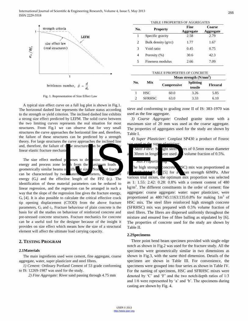
Fig. 1. Representation of Size Effect Law
A typical size effect curve on a full log plot is shown in Fig.1.
The horizontal dashed line represents the failure status according to the strength or yield criterion. The inclined dashed line exhibits a strong size effect predicted by LEFM. The solid curve between the two limiting curves represents the real situation for most structures. From Fig.1 we can observe that for very small structures the curve approaches the horizontal line and, therefore, the failure of these structures can be predicted by a strength theory. For large structures the curve approaches the inclined line and, therefore, the failure of these structures can be predicted by linear elastic fracture mechanics.
The size effect method proposes to determine the fracture
energy and process zone length from the maximum loads of geometrically similar beams of different sizes. Nonlinear fracture can be characterized by two material parameters, the fracture energy (Gf) and the effective length of the FPZ (cf). The identification of these material parameters can be reduced to linear regression, and the regression can be arranged in such a way that the slope of the regression line gives the fracture energy, Gf [4]. It is also possible to calculate the critical effective crack tip opening displacement (CTOD) from the above fracture parameters, Gf and cf. Fracture behaviour of plain concrete is the basis for all the studies on behaviour of reinforced concrete and pre-stressed concrete structures. Fracture mechanics for concrete can be a useful tool for the designer because of the insight it provides on size effect which means how the size of a structural element will affect the ultimate load carrying capacity.
2. TESTING PROGRAM
2.1Materials
The main ingredients used were cement, fine aggregate, coarse aggregate, water, super plasticizer and steel fibres.
1) Cement: Ordinary Portland Cement of 53 grade conforming to IS: 12269-1987 was used for the study.
2) Fine Aggregate: River sand passing through 4.75 mm
TABLE I PROPERTIES OF AGGREGATES
No. Property Fine
Aggregate Coarse
Aggregate 1 Specific gravity 2.58 2.79
2 Bulk density (g/cc) 1.77 1.67
3 Void ratio 0.45 0.75
4 Porosity (%) 30.6 42.3
5 Fineness modulus 2.66 7.09
TABLE II PROPERTIES OF CONCRETE
No. Mix Mean strength (N/mm2)
Compressive Splitting tensile
Flexural
1 HSC 60.0 3.26 5.85
2 SFRHSC 63.0 3.33 6.10
sieve and conforming to grading zone II of IS: 383-1970 was used as the fine aggregate.
3) Coarse Aggregate: Crushed granite stone with a maximum size of 20 mm was used as the coarse aggregate. The properties of aggregates used for the study are shown by Table I.
4) Super Plasticizer: Conplast SP430 a product of Fosroc was used as the super plasticizer.
5) Steel Fibre: Straight steel fibres of 0.5mm mean diameter and 30mm in length were used at a volume fraction of 0.5%.
A. Mix Proportioning
The high strength concrete (HSC) mix was proportioned as per ACI 211.4R-93 [5] for a mean strength 60MPa. After various trial mixes, the optimum mix proportion was selected as 1: 1.55: 2.42: 0.28: 0.8% with a cement content of 480 kg/m3. The different constituents in the order of cement: fine aggregate: coarse aggregate: water: super plasticizer, were proportioned as 480:745:1163:135:0.8% for making 1m3 of HSC mix. The steel fibre reinforced high strength concrete (SFRHSC) mix was prepared with 0.5% volume fraction of steel fibres. The fibres are dispersed uniformly throughout the mixture and ensured free of fibre balling as stipulated by [6]. The properties of concrete used for the study are shown by Table II.
2.2Specimens
Three point bend beam specimen provided with single edge notch as shown in Fig.2 was used for the fracture study. All the specimens were geometrically similar in two dimensions as shown in Fig.3, with the same third dimension. Details of the specimen are shown in Table III. For convenience, the specimens were grouped into four series as shown in Table IV. For the naming of specimens, HSC and SFRHSC mixes were denoted by ‘C’ and ‘F’ and the two notch/depth ratios of 1/3
and 1/6 were represented by ‘a’ and ‘b’. The specimens during
casting are shown by Fig. 4.
255
IJSER

International Journal of Scientific & Engineering Research, Volume 4, Issue 5, May 2013 ISSN 2229-5518
IJSER © 2013
http://www.ijser.org
Fig. 2. Notched Beam Specimen
Fig. 3. Series of Geometrically Similar Specimens
TABLE III SPECIMEN DETAILS
No. Specimen Size (mm) Notch
Depth (a/d)
Span (l/d) Depth
(d) Length
(L) Width
(b) 1 120 400
100 1/3
1/6
2.5 2 140 450 3 160 500 4 180 550
TABLE IV SPECIMEN DESIGNATIONS
No. Series Specimen Depth (mm)
120 140 160 180 1 Ca C1a C2a C3a C4a 2 Cb C1b C2b C3b C4b 3 Fa F1a F2a F3a F4a 4 Fb F1b F2b F3b F4b
2.3Test Procedure
The crack opening displacement was measured with a linear variable differential transformer (LVDT) and the central deflection of the specimen was measured with a dial gauge. A typical three point bending test set up is shown in Fig.5.
Fig. 4. Specimens during Casting
Fig. 5. Three Point Bending Test
Fig. 6. Fracture of HSC Specimen
Fig. 7. Fractured SFRHSC Specimen
2.4. Determination of Fracture Parameters
The size effect law (SEL) which is applied to geometrically
similar specimens of different sizes takes the form as shown by (1).
1
u
N
Bf (1)
The procedure of evaluation of the fracture parameters as stipulated by RILEM TC 89 FMT [7] was followed.The fracture energy (Gf) was obtained from the slope of the regression line, A and the elastic modulus, Ec as shown by (2). The effective length of FPZ (cf) was calculated by (3). The critical effective CTOD
( c ) was determined by (4).
AE
gG
c
f
)( 0 (2)
A
C
g
gc f )(
)(
0
0
(3)
256
IJSER
International Journal of Scientific & Engineering Research, Volume 4, Issue 5, May 2013 ISSN 2229-5518
IJSER © 2013
http://www.ijser.org
2/1
32
c
ff
c E
cG
(4)
The equation of the generalized SEL as shown in (5) could be obtained by making use of the above expressions of fracture parameters [8]. With known )( 0g and )( 0g , the nominal
strength N for any size of specimen or structure can be
determined if Gf and cf for the material are known.
2
1
0
0
0
)(
)()(
dg
gc
g
EG
c
f
f
nN
(5)
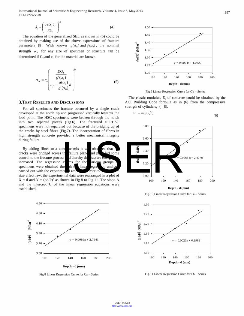
3.TEST RESULTS AND DISCUSSIONS For all specimens the fracture occurred by a single crack
developed at the notch tip and progressed vertically towards the load point. The HSC specimens were broken through the notch into two separate pieces (Fig.6). The fractured SFRHSC specimens were not separated out because of the bridging up of the cracks by steel fibres (Fig.7). The incorporation of fibres in high strength concrete provided a better mechanical integrity during failure.
By adding fibres to a concrete mix it was observed that the
cracks were bridged across the failure plane and provided some control to the fracture process and thereby the fracture energy was increased. The regression curves for the various groups of specimens were obtained through the linear regression analysis carried out with the experimental results. In order to evaluate the size effect law, the experimental data were rearranged in a plot of X = d and Y = (bd/P)2 as shown in Fig.8 to Fig.11. The slope A and the intercept C of the linear regression equations were established.
y = 0.0086x + 2.7941
3.50
3.70
3.90
4.10
4.30
4.50
100 120 140 160 180 200
Depth - d (mm)
(bd/
P)2
(M
Pa)-2
Fig.8 Linear Regression Curve for Ca – Series
y = 0.0024x + 1.0222
1.20
1.25
1.30
1.35
1.40
1.45
1.50
100 120 140 160 180 200
Depth - d (mm)
(bd/
P)2 (
MPa
)-2
Fig.9 Linear Regression Curve for Cb – Series
The elastic modulus, Ec of concrete could be obtained by the ACI Building Code formula as in (6) from the compressive strength of cylinders, '
cf [8]. '
cc f4730E (6)
y = 0.0068 x + 2.4778
3.00
3.20
3.40
3.60
3.80
100 120 140 160 180 200
Depth - d (mm)
(bd
/P)2 (
MP
a)-2
Fig.10 Linear Regression Curve for Fa – Series
y = 0.0020x + 0.8989
1.05
1.10
1.15
1.20
1.25
1.30
100 120 140 160 180 200
Depth - d (mm)
(bd/
P)2 (
MPa
)-2
Fig.11 Linear Regression Curve for Fb – Series
257
IJSER

International Journal of Scientific & Engineering Research, Volume 4, Issue 5, May 2013 ISSN 2229-5518
IJSER © 2013
http://www.ijser.org
TABLE V FRACTURE PARAMETERS BY SIZE EFFECT METHOD T
ype Regression
Values Gf
N/mm
cf mm
c
mm
KIc MPa√m
A C Ca 0.0086 2.7941 0.0508 63.43 0.032 1.28
Cb 0.0024 1.0222 0.0778 73.33 0.042 1.59
Fa 0.0068 2.4778 0.0624 71.14 0.037 1.44
Fb 0.0020 0.8989 0.0907 77.38 0.046 1.74
For the evaluation of fracture parameters (Table V), the non-dimensional energy release rate [ )(g ] and its derivative [ )(g ]
were evaluated for all the series of specimens with the appropriate expressions for )(F and its derivative )(F . With
linear elastic fracture mechanics (LEFM), the critical stress intensity factor, KIc which characterizes the fracture toughness of materials, could be obtained by (7) in plane stress [2]. The nominal maximum bending stress, bN )( is obtained by (8) from
the maximum nominal stress, N [9].
Fc2
Ic GE)K( (7)
N2
ubN
d
l5.1
bd2
lP3)(
(8)
The representation of the SEL in a full log plot as the variation of nominal bending stress against the specimen size is shown by Fig.12. The nominal bending stress at failure was found to be decreasing against the increase of size for both HSC and SFRHSC. For an increase of crack size from 1/6th to 1/3rd of the depth of the structure, the nominal bending stress at failure was reduced considerably. The average reduction in strength for both HSC and SFRHSC specimens was about 72% with respect to the notch variation. The average increase of nominal bending stress for SFRHSC against that of HSC was found to be about 7% for both 1/3rd and 1/6th notch sizes. In addition the flexural strength of HSC was found to be reduced by 68% and 45% by the presence of the initial notch size of 1/3rd and 1/6th of specimen depth. A similar reduction for SFRHSC was found to be 67% and 44%.
Fig.12 SEL Representation
Fig.13 Variation of Bending Stress
The variation of bending stress for the specimen groups and a comparison with the flexural strength of the HSC and SFRHSC is shown by Fig.13.
The stress intensity factor (KI ) obtained by the analytical
study was compared with the experimental values and those obtained by (9) and is shown in Table VI. The expression of geometry dependent function ‘ )(f ’ recommended for the TPB
specimen [10] is given by (9a).
)(f
db
PK I (9)
where - relative notch size ( = a/d) a - notch depth l - span of beam
2/3
2
1212
7.293.315.2)1(99.1
d
l3)(f
(9a)
The average values of SIF were found to be increased by around 19% for the variation of notch size from 1/3rd to 1/6th of specimen size for HSC and an increase of 17% was observed for SFRHSC. The experimental values were found to be over estimating compared to the analytical results. The reason could be due to the formation of relatively large size fracture process zone behind the crack where the energy absorption might be more than that envisaged by the LEFM principles.
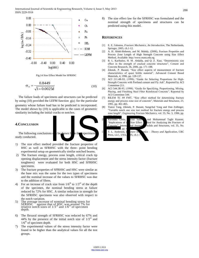
Using the experimental parameters, the SEL for the SFRHSC was formulated as shown by (10) and in Fig.14.
TABLE VI FRACTURE TOUGHNESS COMPARISON
Series KIc (MPa√m)
Experimental Analytical Ca 1.28 0.79
Cb 1.59 0.90
Fa 1.44 0.85
Fb 1.74 0.94
258
IJSER
International Journal of Scientific & Engineering Research, Volume 4, Issue 5, May 2013 ISSN 2229-5518
IJSER © 2013
http://www.ijser.org
Fig.14 Size Effect Model for SFRHSC
d0025.01
8449.0N
(10)
The failure loads of specimens and structures can be predicted by using (10) provided the LEFM function )(g for the particular
geometry whose failure load has to be predicted is incorporated. The model shown by (10) is applicable to the cases of geometric similarity including the initial cracks or notches.
4.CONCLUSION The following conclusions can be drawn from the experimental
study conducted. 1) The size effect method provided the fracture properties of
HSC as well as SFRHSC with the three- point bending experimental setup on geometrically similar notched beams.
2) The fracture energy, process zone length, critical crack tip opening displacement and the stress intensity factor (fracture toughness) were evaluated for both HSC and SFRHSC specimens.
3) The fracture properties of SFRHSC and HSC were similar as the base mix was the same for the two types of specimens and the nominal increase of the values to SFRHSC was due to the addition of fibres.
4) For an increase of crack size from 1/6th to 1/3rd of the depth of the specimen, the nominal bending stress at failure reduced by 72% for HSC. A similar reduction in strength for the SFRHSC specimens was also observed with respect to the notch variation.
5) The average increase of nominal bending stress for SFRHSC against that of HSC was around 7% for relative notch sizes of 1/3 rd and 1/6 th of specimen depth.
6) The flexural strength of SFRHSC was reduced by 67% and
44% by the presence of the initial notch size of 1/3rd and 1/6th of specimen depth.
7) The experimental values of the stress intensity factor were found to be higher than the analytical values for all the test groups.
8) The size effect law for the SFRHSC was formulated and the nominal strength of specimens and structures can be predicted using this model.
REFERENCES [1] E. E. Gdoutos, Fracture Mechanics, An Introduction, The Netherlands,
Springer, 2005, ch.1-12. [2] A. H. Abdel-Reheem, and M. Mahdy, (2006), Fracture Properties and
Process Zone Length of High Strength Concrete using Size Effect Method, Available: http://www.mans.edu.eg.
[3] B. L. Karihaloo, H. M. Abdalla, and Q. Z. Xiao, “Deterministic size
effect in the strength of cracked concrete structures”, Cement and
Concrete Research, 36, 2006, pp. 171-188. [4] Zdenek, P. Bazant, “Size effect aspects of measurement of fracture
characteristics of quasi brittle material”, Advanced Cement Based
Materials, 4, 1996, pp. 128-137. [5] ACI 211.4R-93, (1998), “Guide for Selecting Proportions for High-
Strength Concrete with Portland cement and Fly Ash”, Reported by ACI Committee 211.
[6] ACI 544.3R-93, (1998), “Guide for Specifying, Proportioning, Mixing,
Placing, and Finishing Steel Fiber Reinforced Concrete”, Reported by
ACI Committee 544. [7] RILEM TC 89 FMT, “Size effect method for determining fracture
energy and process zone size of concrete”, Materials and Structures, 23,
1991, pp. 461-465. [8] Tianxi Tang, Zdenek, P. Bazant, Sungchul Yang and Dan Zollinger,
“Variable notch one size test method for fracture energy and process
zone length”, Engineering Fracture Mechanics, vol. 55, No. 3, 1996, pp. 383-404.
[9] Ravindra Gettu, Hector Saldivar and Mohammad Taghi Kazemi, “Implications of the Size Effect Method for Analyzing the Fracture of Concrete”, International Journal of Solids and Structures, vol. 35, No. 31-32, 1998, pp. 4121-4132.
[10] T. L. Anderson, Fracture Mechanics – Theory and Application, CRC Press, LLC, USA, 1995, ch.1-7.
259
IJSER