Fracture Mechanics of Concrete on The Basis of Finite ... Mechanics of Concrete on The Basis of...
10
Fracture Mechanics of Concrete on The Basis of Finite Element by Applying InverseAnalysis Method Atur P. N. Siregar Civil Engineering Department, Tadulako University, Indonesia Jl. SoekarnoHatta Km. 9, Palu, Sulawesi Tengah, Indonesia (94118) [email protected] Abstract—This study is to evaluate the effect of compressive strength of the concrete on the fracture mechanics of the concrete through finite element (FE) analysis. Cohesive crack and crack band model were employed to observe the significance of increasing compressive strength of the concrete on the value of fracture energy and propagation of crack, respectively. A set of notched beams specimens manufactured with compressive strength concrete of 36, 45, 53 and 95 MPa were experimentally investigated. On the basis of invers analysis, the tensile softening curve of the concrete was intended to create for a specific compressive strength of the concrete which was then used as an input parameter for FE model. The value of fracture energy was calculated based on FE result based on the load against crack opening displacement curve. Comparison was carried out between FE and experimental result. This study was found that increasing compressive strength of the concrete markedly influenced on the fracture energy of the concrete and induced the cracking path in the concrete. Keyword-Concrete strength, Fracture energy, Fracture mechanics, Inverse analysis I. INTRODUCTION Amount of dissipated fracture energy absorbed in fracture process of material is a parameter used in representing cracking resistance and fracture toughness of a material by the means of mode-I (opening mode) [1] and is reckoned as a fracture material property in fracture mechanics. The compressive strength of the concrete which is a dominant mechanical property of concrete is predominantly used as a basis of other mechanical properties of concrete as well as fracture parameter. Model code 1990 [2] and model code 2010 [3] proposed to calculate the dissipated fracture energy of the concrete based on its compressive strength in which it tends to use for normal strength concrete below 50 MPa as those equations was derived on the basis of normal strength concrete. Over the past 25 years, however, there has been increasing use of, and reliance on, high strength concrete (f c ’ > 50 MPa) to build ultra-high-rise buildings and long-span bridges [4]. The increase of compressive strength may induce the fracture characteristic of the concrete and then of reinforced concrete structure. Fracture energy of concrete is derived on the basis of the load-displacement curve [5] or the load-elongation curve [6] of cracked specimen. These tensile softening curves describe the fracture process zone of the concrete [1] which is implied the total dissipated fracture energy during the fracture process of the concrete. However, researchers have argued on the use of testing method in computing fracture energy of the concrete that an effect of size (called ‘size effect’) contributes to the value of fracture energy of the concrete donated by testing method used [7, 8]. In order to elude the size effect in observing the effect of concrete strength on dissipated fracture energy, in this study, the tensile softening curves of specimen measured by experimental result is then created by inverse analysis [1] as fracture parameter input in modeling to which cohesive crack model proposed by Hillerborg (1976) is engaged in concerning on the effect of the concrete strength, and smeared crack model [9] is of interest of crack path through the concrete. ISSN (Print) : 2319-8613 ISSN (Online) : 0975-4024 Atur P. N. Siregar / International Journal of Engineering and Technology (IJET) DOI: 10.21817/ijet/2017/v9i3/170903511 Vol 9 No 3 Jun-Jul 2017 2542
-
Upload
hoangtuong -
Category
Documents
-
view
218 -
download
0
Transcript of Fracture Mechanics of Concrete on The Basis of Finite ... Mechanics of Concrete on The Basis of...

Fracture Mechanics of Concrete on The Basis of Finite Element by Applying
InverseAnalysis Method Atur P. N. Siregar
Civil Engineering Department, Tadulako University, Indonesia Jl. SoekarnoHatta Km. 9, Palu, Sulawesi Tengah, Indonesia (94118)
Abstract—This study is to evaluate the effect of compressive strength of the concrete on the fracture mechanics of the concrete through finite element (FE) analysis. Cohesive crack and crack band model were employed to observe the significance of increasing compressive strength of the concrete on the value of fracture energy and propagation of crack, respectively. A set of notched beams specimens manufactured with compressive strength concrete of 36, 45, 53 and 95 MPa were experimentally investigated. On the basis of invers analysis, the tensile softening curve of the concrete was intended to create for a specific compressive strength of the concrete which was then used as an input parameter for FE model. The value of fracture energy was calculated based on FE result based on the load against crack opening displacement curve. Comparison was carried out between FE and experimental result. This study was found that increasing compressive strength of the concrete markedly influenced on the fracture energy of the concrete and induced the cracking path in the concrete.
Keyword-Concrete strength, Fracture energy, Fracture mechanics, Inverse analysis
I. INTRODUCTION
Amount of dissipated fracture energy absorbed in fracture process of material is a parameter used in representing cracking resistance and fracture toughness of a material by the means of mode-I (opening mode) [1] and is reckoned as a fracture material property in fracture mechanics. The compressive strength of the concrete which is a dominant mechanical property of concrete is predominantly used as a basis of other mechanical properties of concrete as well as fracture parameter. Model code 1990 [2] and model code 2010 [3] proposed to calculate the dissipated fracture energy of the concrete based on its compressive strength in which it tends to use for normal strength concrete below 50 MPa as those equations was derived on the basis of normal strength concrete. Over the past 25 years, however, there has been increasing use of, and reliance on, high strength concrete (fc
’> 50 MPa) to build ultra-high-rise buildings and long-span bridges [4]. The increase of compressive strength may induce the fracture characteristic of the concrete and then of reinforced concrete structure.
Fracture energy of concrete is derived on the basis of the load-displacement curve [5] or the load-elongation curve [6] of cracked specimen. These tensile softening curves describe the fracture process zone of the concrete [1] which is implied the total dissipated fracture energy during the fracture process of the concrete. However, researchers have argued on the use of testing method in computing fracture energy of the concrete that an effect of size (called ‘size effect’) contributes to the value of fracture energy of the concrete donated by testing method used [7, 8]. In order to elude the size effect in observing the effect of concrete strength on dissipated fracture energy, in this study, the tensile softening curves of specimen measured by experimental result is then created by inverse analysis [1] as fracture parameter input in modeling to which cohesive crack model proposed by Hillerborg (1976) is engaged in concerning on the effect of the concrete strength, and smeared crack model [9] is of interest of crack path through the concrete.
ISSN (Print) : 2319-8613 ISSN (Online) : 0975-4024 Atur P. N. Siregar / International Journal of Engineering and Technology (IJET)
DOI: 10.21817/ijet/2017/v9i3/170903511 Vol 9 No 3 Jun-Jul 2017 2542

The lmm depttensile sois employ
A setextractedpropertiecurve obtstrength modelinginto 7 pexperimecurve, thdecided tcurve are
The Dmodel wacreating 4in the cenwas empThe sameusing the
load against cth, and 500 moftening curveyed, Fig. 1.
t of experimed as discussedes of concretetained as showused to prod
g, were establpoints of desental results oe multi-linearto use as obtae shown in Tab
DIANA versioas chosen to u4663 triangulnter of the bealoyed in analye material pro
e smeared crac
crack width dimm length usie through inve
ental data of d in the next , i.e. moduluswn in Fig. 2. duce the tenslished over niscending dataf the specime
r constitutive rained by concble I.
on 9.4 was enuse in modelinar plane stressam in order toysis. A centra
operty of concck model [9] i
II. DEFININ
isplacement cing three-poiners analysis. T
Fig. 1.Algo
four differensection. The
s of elasticity The average sile softening ine sets of da
a in order toens with comprelationship ocrete strength
III. FINITE E
ngaged in creang. The specims elements for
o simulate the al point load ocrete, type of min order to visu
NG OF SOFTEN
curve of nine nt bend test mThe invers ana
orithm of inverse
nt concrete str linear-part o(E), tensile s
stress against curve param
ata. The averao provide an pressive strengf tension softeof 53 MPa. T
ELEMENT (FE
ating a modelmen used in tr concrete mamaterial prop
of 1 mm verticmesh elementualize the crac
NING CURVE
beam specimmethod was ualysis algorith
analysis [1].
rengths was pof curve was strength of cocrack width c
meter, which waged tensile so
adequate mugth of 45 and ening curve ofThe constituti
E) MODELING
l to replicate tthe experimentrix, Fig. 3. A
perties of beamcal displacemt and geometrck path physic
mens with sizeused as the bam established
prepared in wshaped on th
oncrete (ft), ancurves of eachwas then emoftening curvulti-linear so53 MPa prod
f both strengthive relationshi
the experimennt was then nuAn interface linm since the co
ment was appliry of model wcally through
e of 45 mm wasis of determd by Kwon et
which those dhe basis of mnd the softeninh compressive
mployed as anves were then ftening curveduced a relativh (45 and 53 Mips of tensile
ntal specimensumerically simne element waohesive crack ied on the bea
were applied onthe concrete.
width, 100 mining the
al. (2008)
data were mechanical ng-part of e concrete n input in
extracted e. As the vely same MPa) was softening
s. The 2D mulated by as applied model [6]
am model. n a model
ISSN (Print) : 2319-8613 ISSN (Online) : 0975-4024 Atur P. N. Siregar / International Journal of Engineering and Technology (IJET)
DOI: 10.21817/ijet/2017/v9i3/170903511 Vol 9 No 3 Jun-Jul 2017 2543

TABLE I. Multi-linear Softening Curves of Concrete
Item ft,max
(MPa) E
(MPa) ft
(MPa) Crack Opening
Displacement(mm)
fc’ = 36 MPa 3.14 28200 ft 0 0.78ft 0.11% ε 0.48ft 0.90% ε 0.24ft 1.89% ε
0.12ft 4.97% ε 0.08ft 10.00% ε 0 ε
fc’ = 53 MPa 3.84 34200 ft 0 0.78ft 0.11% ε 0.48ft 0.90% ε 0.24ft 2.89% ε 0.12ft 7.20% ε 0.08ft 25.00% ε 0 ε
fc’ = 95 MPa 6.35 45000 ft 0 0.68ft 0.22% ε 0.43ft 1.26% ε 0.23ft 3.89% ε 0.04ft 7.78% ε 0.02ft 17.93% ε 0 ε
IV. EXPERIMENT WORKS
A. Concrete Mix Proportions
Four different compressive strengths were manufactured in order to produce notched beam specimens as discussed in the next section, Table II.
Fig. 2.A method in averaging stress-crack opening displacement of experimental results.
ISSN (Print) : 2319-8613 ISSN (Online) : 0975-4024 Atur P. N. Siregar / International Journal of Engineering and Technology (IJET)
DOI: 10.21817/ijet/2017/v9i3/170903511 Vol 9 No 3 Jun-Jul 2017 2544

Fig. 3.Finite element model for specimen replication.
B. Specimen Preparations
The compressive strength of concrete was measured using cubes of 100 x 100 x 100 mm regarding to BS EN 12390: Part 3(2000) [10]. The softening curves was defined using beam specimens with size of 45 mm width, 100 mm depth, and 500 mm length tested in three-point bend (TPB). All of the specimens were applied water cured method for 28 days. A water-cooled diamond rotary cutter with 2.5 mm width was used to create 40 mm notch depth (ao), Fig. 3.
Table II. Concrete Mix Proportions
Item fc
’= 36 Mpa fc’= 45 Mpa fc
’= 53 Mpa fc’= 95 Mpa
Ratio (kg) Ratio (kg) Ratio (kg) Ratio (kg)
Cement 1 1 1 1 Fly ash 0.20 0.25 0.25 0.25 Microsilica - 0.03 0.05 0.10 Total water 0.53 0.40 0.31 0.23
dia. 16 mm 1.95 1.31 1.31 1.74 dia. 10 mm 1.00 0.52 0.52 0.54 Sand 2.18 1.91 1.91 2.07
Superplasticiser - - 0.002 0.0042
C. Three-point Bend (TPB) Test Set-up
The geometry of TPB test set up is shown in Fig. 3. The testing was carried out using a servo-hydraulic closed-loop testing machine, Fig. 4. A vertical displacement of 0.01 mm/s [11] was applied to control subjected load. The crack opening displacement was measured by a calibrated linear variable differential transducer (LVDT)with 7.5 mm capacity and ± 0.0007 mm linearity.Before submitting your final paper, check that theformat conforms to this template. Specifically, check theappearance of the title and author block, the appearance ofsection headings, document margins, column width, column spacing and other features.
V. DETERMINATION OF FRACTURE ENERGY
Fracture process of material consumes amount of energy until totally failure. The amount of energy absorbed of material to fracture is used to classify fracture resistance of material. Fracture toughness and dissipated fracture energy of material have been extensively employed to characterise the fracture resistance of material. Concrete as a quasi-brittle material is proposed to use the fracture energy (GF) in observing the degree of the fracture resistance. In this study the fracture energy was calculated based on the RILEM TC50-FCM recommendation (1985) [5]:
(1)
ISSN (Print) : 2319-8613 ISSN (Online) : 0975-4024 Atur P. N. Siregar / International Journal of Engineering and Technology (IJET)
DOI: 10.21817/ijet/2017/v9i3/170903511 Vol 9 No 3 Jun-Jul 2017 2545

In Eq. (1), GFis the total fracture energy, Wo is the area under the load-deflection curve, m is the total mass of specimen between supports, g is gravity, δois the end deflection at P=0, and D,ao and t are the depth of the beam, depth of the notch, and width of the beam, respectively.
VI. RESULTS AND DISCUSSIONS
Fig. 5 shows the beam responses on applied load by the means of load against crack opening displacement for various concrete strengths. The average peak loads of beams manufactured with compressive strength of 95, 53, 45 and 36 MPa are 4170, 2448, 2510 and 2140 N respectively. As the compressive strength of concrete controlling the quality of interfacial zone matrix which is the weakest link in the concrete [12], increasing compressive strength of concrete by reducing ratio of water to cement as well as adding up supplementary cementitious materials such as fly ash and microsilica, can reduce considerably the degree of porosity in concrete. Consequently, the strength of interfacial zone matrix rises as the compressive strength of the concrete rises and thus applied load subjecting on the beam is increased as shown in Fig. 5.
The characteristic of the concrete after the peak load can be derived on the slop of descending curve. Albeit it is only descriptive analysis over the curve, it assists in describing the effect of compressive strength on the post-peak behavior of concrete. Fig. 5 shows that the descending curve slope of compressive strength of 95 MPa is moderately steep compared to others in which the descending curve of compressive strength of 36, 45, and 53 MPa tend to have a relatively same slope. However, it is a descriptive analysis over the load-crack opening displacement curve. The area under the curve representing the total energy dissipated during fracture process [5] can be engaged to calculate the fracture energy of concrete for evaluating sincerely the effect of compressive strength of concrete on the characteristic of concrete.
Fig. 4. A servo-hydraulic closed-loop testing machine
Fig. 5.Load-crack opening displacement of various concrete strengths.
0
500
1000
1500
2000
2500
3000
3500
4000
4500
0 0.1 0.2 0.3 0.4 0.5
Load
(N)
Crack opening displacement (mm)
fc'=95 MPa
fc'=53 MPa
fc'=45 MPa
300 45
LVDT
P
▪100 ●
P
LVDT
ISSN (Print) : 2319-8613 ISSN (Online) : 0975-4024 Atur P. N. Siregar / International Journal of Engineering and Technology (IJET)
DOI: 10.21817/ijet/2017/v9i3/170903511 Vol 9 No 3 Jun-Jul 2017 2546
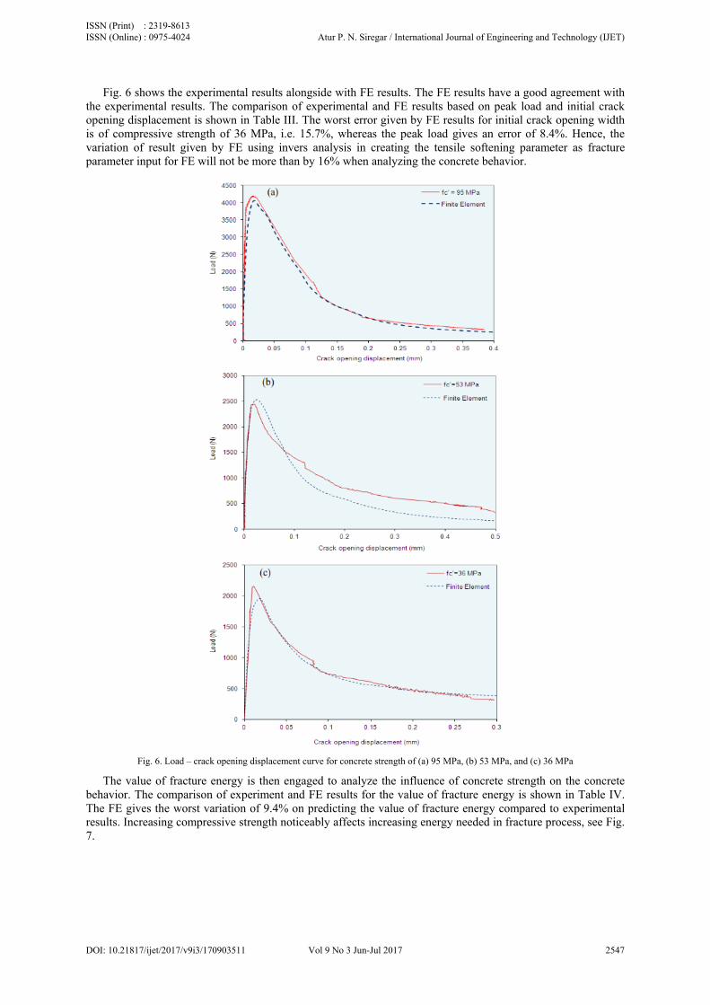
Fig. 6 shows the experimental results alongside with FE results. The FE results have a good agreement with the experimental results. The comparison of experimental and FE results based on peak load and initial crack opening displacement is shown in Table III. The worst error given by FE results for initial crack opening width is of compressive strength of 36 MPa, i.e. 15.7%, whereas the peak load gives an error of 8.4%. Hence, the variation of result given by FE using invers analysis in creating the tensile softening parameter as fracture parameter input for FE will not be more than by 16% when analyzing the concrete behavior.
Fig. 6. Load – crack opening displacement curve for concrete strength of (a) 95 MPa, (b) 53 MPa, and (c) 36 MPa
The value of fracture energy is then engaged to analyze the influence of concrete strength on the concrete behavior. The comparison of experiment and FE results for the value of fracture energy is shown in Table IV. The FE gives the worst variation of 9.4% on predicting the value of fracture energy compared to experimental results. Increasing compressive strength noticeably affects increasing energy needed in fracture process, see Fig. 7.
ISSN (Print) : 2319-8613 ISSN (Online) : 0975-4024 Atur P. N. Siregar / International Journal of Engineering and Technology (IJET)
DOI: 10.21817/ijet/2017/v9i3/170903511 Vol 9 No 3 Jun-Jul 2017 2547

Fig. 7. The effect of concrete strength on dissipated fracture energy
Table III. Comparison of Experimental and FE Results on Peak Load and Initial Crack Opening Width.
Strength Peak Load Initial crack opening width
Experimental data(mean value)
Finite element
Error Experimental
data(mean value) Finite
element Error
MPa N N % N/m N/m %
36 2139.8 1959.2 -8.4 0.0045 0.0038 -15.7 53 2447.7 2529.9 3.4 0.0016 0.0015 -7.9
95 4169.9 4052.3 -2.8 0.0040 0.0034 -13.9
Table IV. Comparison of Experimental and FE Results on Fracture Energy
Strength Fracture energy, GF
Experimental data (mean value) Numerical simulation Error MPa N/m N/m %
36 117.6 119.5 1.6 53 131.3 118.9 -9.4 95 164.9 169.9 3.0
VII. CRACK PROPAGATION OF CONCRETE
Fracture energy of the concrete as discussed in the previous section is then employed as fracture parameter input for finite element modeling by applying crack band models in observing the crack propagation of concrete. Fracture process of the concrete is observed at three points representing propagation of crack in the concrete, Fig. 8. The first point shows the stress distribution at the notch of beam while the apparent crack is occurred in the concrete. Crack propagates as the applied load increases until the critical point (the second point) before final failure of the concrete happened. The final failure of the concrete is described as the third point.
020406080
100120140160180
0 25 50 75 100 125
Frac
ture
ene
rgy,
N/m
Compressive strength of concrete (MPa)
ISSN (Print) : 2319-8613 ISSN (Online) : 0975-4024 Atur P. N. Siregar / International Journal of Engineering and Technology (IJET)
DOI: 10.21817/ijet/2017/v9i3/170903511 Vol 9 No 3 Jun-Jul 2017 2548

Fig. 8. A typical load against crack opening displacement curves
Fig. 9 shows that the fracture process zone at the notch for concrete strength of 53 and 95 MPa tends to be wider but smaller than that of 36 MPa, and vice versa. The width of fracture process zone is controlled by constituents of materials in the concrete such as water, cement and maximum particle size [13]. The compressive strength of concrete influenced by water/cement ratio, dictates the strength of interfacial zone matrix. The higher strength of interfacial zone matrix and maximum particle size contribute significantly to the distribution of applied stress amongst particles. Hence, higher strength of concrete and larger maximum particle size tends to have a wider fracture process zone.
Fig. 9. Cracking of concrete at peak load for (a) fc=36 MPa, (b) fc=53 MPa, and (c) fc=95 MPa.
Increasing applied load after peak load propagates the apparent crack as shown in Fig. 10. Crack propagation of the concrete with the strength of 36 MPa demonstrates a more tortuous cracking path compared to concrete strength of 53 and 95 MPa. As a consequence of the degree of interfacial matrix strength, crack propagation of low strength concrete tends to develop surrounding the particles and ends up with a tortuous cracking path. The final failure as shown in Fig. 11 describes the effect of concrete strength on the residual strain (marked as the red element) along the cracking path. The residual strain value of concrete strength of 36 MPa is not existed along the cracking path. However, in the concrete strength of 53 and 95 MPa is obviously occurred and having a relatively long zone. This indicates that tensile strength of concrete still contribute in resisting crack opening and therefore concrete strength will involve in post-peak behavior of concrete.
(a) (b)
(c)
ISSN (Print) : 2319-8613 ISSN (Online) : 0975-4024 Atur P. N. Siregar / International Journal of Engineering and Technology (IJET)
DOI: 10.21817/ijet/2017/v9i3/170903511 Vol 9 No 3 Jun-Jul 2017 2549

Fig. 10. Propagation of crack after peak load for (a) fc=36 MPa, (b) fc=53 MPa, and (c) fc=95 MPa.
Fig. 11. Final cracking of concrete (a) fc=36 MPa, (b) fc=53 MPa, and(c) fc=95 MPa.
VIII. CONLUSIONS
Some conclusions can be drawn on this study:
1. Based on the FE, concrete strength evidently affects the dissipated fracture energy of the concrete in which the dissipated fracture energy ofthe concrete increases as the strength of the concrete increases.
2. Although on the basis of qualitative analysis of FE model using crack band model, the crack path of concrete is dependent on the compressive strength of the concrete.
(a) (b)
(c)
(c)
(a)
(b)
ISSN (Print) : 2319-8613 ISSN (Online) : 0975-4024 Atur P. N. Siregar / International Journal of Engineering and Technology (IJET)
DOI: 10.21817/ijet/2017/v9i3/170903511 Vol 9 No 3 Jun-Jul 2017 2550

REFERENCES [1] S. H. Kwon, Z. Zhao, and S. P. Shah, ‘Effect of specimen size on fracture energy and softening curve of concrete: Part II. Inverse
analysis and softening curve”, Cement and Concrete Research, vol. 38, pp. 1061–1069, 2008. [2] Comitte Euro-International du Beton, CEB-FIP Model Code 1990, Thomas Telford, UK, 1993. [3] Comitte Euro-International du Beton, CEB-FIP Model Code 2010 (first draft), Fib Bulletin 55: Model Code 2010, First complete draft
– Volume 1, Lausanne, Switzerland, 2010. [4] American Concrete Institute, Report on High Strength Concrete, ACI-363R-10, Farmington Hills, USA, 2010. [5] RILEM TC50-FCM recommendation, “Determination of the fracture energy of mortar and concrete by means of three-point bend tests
on notched beams”, Material and Structures, vol. 18, no. 106, pp. 285-290, 1985. [6] A. Hillerborg, M. Modeer, and P. E. Petersson, “Analysis of crack formation and crack growth by means of fracture mechanics and
finite element”, Cement and Concrete Research, vol. 6, pp. 773-782, 1976. [7] J. Planas, M. Ellices, and G. V. Guinea, “Measurement of the fracture energy using three point bending tests: part 2-influence of bulk
energy dissipation”, Material and Structures, vol. 52, pp. 305-312, 1992. [8] X. H. Guo and R. I. Gilbert, “The effect of specimen size on the fracture energy and softening function of concrete”, Material and
Structures, vol. 33, pp. 309-316, 2000. [9] Z. P. Bazant and B. H. Oh, 1983 in S. P. Shah, et al., Fracture Mechanics of Concrete, John Willey & Sons, USA, 1995. [10] BS EN 12390-3, Testing Hardened Concrete, European Committee for Standardization, Brussels, 2001. [11] X. Zhang and S. Xu, “A comparative study of five approaches to evaluate double-K fracture toughness parameters of concrete and size
effect analysis”, Engineering Fracture Mechanics, vol. 78, no. 10, pp. 2115-2138, 2011. [12] B. Chen andJ.Liu, “Effect of aggregate on the fracture behaviour of high strength concrete”,Construction and Building Materials, vol.
18, no. 8, pp. 585-590, 2004. [13] Z. Bazant and M. T. Kazemi, “Determination of fracture energy, process zone length and brittleness number from size effect with
application to rock and concrete”, International Journal of Fracture, vol. 44, pp. 111-131, 1990.
AUTHOR PROFILE
Atur P. N. Siregarwas born in Kupang, Indonesia in 1970. He graduated with B. E. in civil engineering from GadjahMadaUniversity, and received his Master degree in civil engineering from University of Sheffield, UK. In 2016 he received his PhD in civil engineering from University of Surrey, UK.His research interests are in area of composite materials, reinforced concrete structures, and vibrations of structures. He is a lecturer of Tadulako University, Indonesia.
ISSN (Print) : 2319-8613 ISSN (Online) : 0975-4024 Atur P. N. Siregar / International Journal of Engineering and Technology (IJET)
DOI: 10.21817/ijet/2017/v9i3/170903511 Vol 9 No 3 Jun-Jul 2017 2551