Fracture Mechanics, Fracture Criteria and Fracture … · 2) FlawSize (a) Brittle fractures...
40
-. ___–-. –-. @ ,UWC,,* THE SOCIETYOF NAVALARCHITECTSANO MARINEENGINEERS *’ 74 Trinity Place, NewY.rk,N.Y.,10006 f t Pw.( t.bePresented 8%ths Sh{pSt,uctu,e SynPOSWc : Washln@e”, D.C., October 6.8,1975 :* %$ **,..3* Fracture Mechanics, Fracture Criteria and Fracture Control for Welded Steel Ship Hulls Professor S. T. Rolfe, Visitor, University of Kansas, Lawrence, Kansas @ Cowmht 1’375byTheSoc’etyofNavalAmhltect$and MarineEngineers ASSTffACT [~ This paper describes a comprehen- sive toughness criteria for welded ship hulls that can be used for shipbuilding steels of all strength levels. Because of the fact that stress concentrations are al”ays present in large corfplex welded structures such as ships, high local stresses as well as discontirmities or flaw “ill be present in welded ship hulls. Therefore, primary emphasis in the proposed fracture-control guidelines is placed on the use of steels with moderate levels of notch-toughness and on the use of properly designed crack arresters, rnwever, the importance of proper design and fabrication should be emphasized. In general, concepts of fracture mechanics are used to develop the mat- erial toughness level that is required for fail-safe operation of welded ship hulls. This toughness level is esti- mated to be K /. level of 0.9 at 32°F (O“C), where ~~D ~~ the critical mater- ial toughness under conditions of dynami- c loading and u is the yield strength of the material ~~der the same dynamic loading. The assumption that ships are loaded dynamically is made because little information on loading rates existed at the time of this study and ships are basically single-load path structures. Hence the assumption of dynamic loading is conservative and needs to be studied further, in vie” of the excellent service history of welded steel ships. Because the desired le”el of toughness cannot be measured directly using current fracture mechanics tests, the requirements are established in terms of the NDT (nil-ductility trans- ition) temperature and DT (dynamic tear) test values for base metal, weld metal, and heat-affected-zone materials used in primary load-carrying Embers. Althouqh the criteria presented in this paper are primarily material specifications , the importance of proper design (avoiding details that lead to P-1 stress concentrations ) and proper fab- rication (good quality welding and in- spection) is emphasized. 1“ general, the results of this investigation have developed conserva- tive material-toughness requirements for ship steels of all strength levels which, in combination with properly designed crack arresters, shodd result in rational fracture-control guidelines that will minimize the probability of brittle fractures in welded ship bulls consistent “ith eco”ondc realities. ,, GENERAL PRIELEM OF BRITTLE FSACTURE IN SHIPS Although welded ship failures have occurred since the early 1900 vs, it was not until the la,rge‘number of World war II ship failures that the problem was fully appreciated] )*. Of the approximately 5,000 merchant ship?, built during World War 11, over 1,000 had developed cracks of considerable size by 1946. Between 1942 and 1952, more than 200 ships had sustained frac- tures classified as serious, and at least nine T-2 tankers and seven Liberty ships had broken completely in two as a result of brittle fractures. The majOr- ity of fractures in the Liberty ships started at square hatch corners or square cutouts at the top of the sheer- strake. Design changes involving romd- ing and strengthening of the hatch corners, renvving sguare cutouts in the sheerstrake, and adding riveted crack arresters in various locations led to inanediate reductions in the incidence of failuresz ). Most of the fractures in the T-2 tankers originated in defects in bottom shell butt welds. The use of crack arresters a“d improved workman- ship reduced the incidence of failures in these vessels. . Studies indicated that in addi- tion to design faults, steel quality also was a primary factor that contri- buted to brittle fracture in “elded ship hulls’) . Therefore, in 1947, the American Bureau of Shipping introduced restrictions on the chemical composition &-
Transcript of Fracture Mechanics, Fracture Criteria and Fracture … · 2) FlawSize (a) Brittle fractures...
-. ___–-. –-.
@
,UWC,,* THE SOCIETYOF NAVALARCHITECTSANO MARINE ENGINEERS*’ 74 TrinityPlace,New Y.rk,N.Y.,10006
ft Pw.(t.bePresented8%thsSh{pSt,uctu,eSynPOSWc
:Washln@e”,D.C.,October6.8,1975
:*
%$**,..3*
Fracture Mechanics, Fracture Criteria andFracture Control for Welded Steel Ship HullsProfessor S. T. Rolfe, Visitor, University of Kansas, Lawrence, Kansas
@ Cowmht1’375by The Soc’etyof NavalAmhltect$and MarineEngineers
ASSTffACT[~This paper describes a comprehen-
sive toughness criteria for welded shiphulls that can be used for shipbuildingsteels of all strength levels. Becauseof the fact that stress concentrationsare al”ays present in large corfplexwelded structures such as ships, highlocal stresses as well as discontirmitiesor flaw “ill be present in welded shiphulls. Therefore, primary emphasis inthe proposed fracture-control guidelinesis placed on the use of steels withmoderate levels of notch-toughness andon the use of properly designed crackarresters, rnwever, the importance ofproper design and fabrication shouldbe emphasized.
In general, concepts of fracturemechanics are used to develop the mat-erial toughness level that is requiredfor fail-safe operation of welded shiphulls. This toughness level is esti-mated to be K /. level of 0.9 at 32°F(O“C), where ~~D ~~ the critical mater-ial toughness under conditions of dynami-c loading and u is the yield strengthof the material ~~der the same dynamicloading. The assumption that ships areloaded dynamically is made becauselittle information on loading ratesexisted at the time of this study andships are basically single-load pathstructures. Hence the assumption ofdynamic loading is conservative andneeds to be studied further, in vie”of the excellent service history ofwelded steel ships.
Because the desired le”el oftoughness cannot be measured directlyusing current fracture mechanics tests,the requirements are established interms of the NDT (nil-ductility trans-ition ) temperature and DT (dynamic tear)test values for base metal, weld metal,and heat-affected-zone materials usedin primary load-carrying Embers.
Althouqh the criteria presentedin this paper are primarily materialspecifications , the importance of properdesign (avoiding details that lead to
P-1
stress concentrations ) and proper fab-rication (good quality welding and in-spection) is emphasized.
1“ general, the results of thisinvestigation have developed conserva-tive material-toughness requirementsfor ship steels of all strength levelswhich, in combination with properlydesigned crack arresters, shodd resultin rational fracture-control guidelinesthat will minimize the probability ofbrittle fractures in welded ship bullsconsistent “ith eco”ondc realities. ,,
GENERAL PRIELEM OF BRITTLE FSACTURE INSHIPS
Although welded ship failureshave occurred since the early 1900 vs,it was not until the la,rge‘number ofWorld war II ship failures that theproblem was fully appreciated] )*. Ofthe approximately 5,000 merchant ship?,built during World War 11, over 1,000had developed cracks of considerablesize by 1946. Between 1942 and 1952,more than 200 ships had sustained frac-tures classified as serious, and atleast nine T-2 tankers and seven Libertyships had broken completely in two as aresult of brittle fractures. The majOr-ity of fractures in the Liberty shipsstarted at square hatch corners orsquare cutouts at the top of the sheer-strake. Design changes involving romd-ing and strengthening of the hatchcorners, renvving sguare cutouts in thesheerstrake, and adding riveted crackarresters in various locations led toinanediate reductions in the incidenceof failuresz ). Most of the fracturesin the T-2 tankers originated in defectsin bottom shell butt welds. The use ofcrack arresters a“d improved workman-ship reduced the incidence of failuresin these vessels.
.Studies indicated that in addi-
tion to design faults, steel qualityalso was a primary factor that contri-buted to brittle fracture in “eldedship hulls’) . Therefore, in 1947, theAmerican Bureau of Shipping introducedrestrictions on the chemical composition
&-
of steels and in 1949, Lloyds Registerstated that “when the main structureof a ship is intended to be wholly orpartially welded, the committee mayrequire parts of primary structuralimportance to be steel, the propertiesand process of manufacture of whichhave been specially approved for thispurpose’ ).”
In spite of design improvements,the increased use of crack arresters,improvements in quality of workmanship,and restrictions on the chemical com-position of ship steels during thelater 1940’s, brittle fractures stilloccurred in ships in the early 1950’ss ).Bet”een 1951 and 1953, two conparative-lY new all-welded cargo ships and atransversely framed welded tanker broke.in two. ln the winter of 1954, a long-itudinally framed welded tanker con-structed of improved steel qualityusing up-to-date concepts of good de-sign and welding quality broke in two’ ).
During the 1950’s, seven Classifi-cation Societies responsible for theclassification of ships (AmericanBureau of Shipping, Bureau Veritas,Germanischer Lloyd, Lloyd’s Register ofShipping, Nipon Kaiji Kyokai, DetNorske Veritas, and Registro ItaliannoNa”ale) held n“mero”s meetings and in1959 published the Unified Requirementsfor Ship Steels ‘). These requirementsspecified various manufacturing methods,chemical composition, or Charpy V-Notch impact requirements for fivegrades of steel.
Since the late 1950’s (althoughthe actual number has been low) brittlefractures have still occurred in shipsas indicated by Boyd’ s description often such failures between 1960 and 1965and a number of unpublished reports ofbrittle fractures in welded ships since19657 ), as well as the brittle fracturethat occurred in the Ingram Bar% in1972.
Therefore, although it has beenaPPrOXi~telY 30 years since the prob-lem of brittle fracture in welded shiphulls was first recognized as a signif-icant problem for the ship-buildingindustry, brittle fractures still occurin ships. while it is true that durinqthis time considerable research has ledto various changes in design, fabrica-tion, and materials so that the inci-dence of brittle fractures in weldedship hulls has been reduced markedlya ),nonetheless, brittle fractures continueto occur in welded ship hulls fabricat-ed with ordinary-strength steels. Withthe use of higber-strength steels,there is a definite concern that brittlefractures may occur in these steels also.
* See References
Currently there are no specificfracture-control guidelines or overalltouqhness criteria available for theppact~ing naval architect tO specifyin designing welded steel ship hulls ofall strength levels. Therefore, thepurpose of this paper is to providerational fracture-control guidelinesconsistent with economic realitieswhich, when implemented, will minimizethe probability of brittle fractures inwelded ship hulls. Although the factis rarely stated, the basis of struc-tural design in all large complex weldedstructures is an attempt to optimizethe desired performance requirementsrelative to cost considerations (mater-ials, design, fabrication) so that theprobability of failure (and its economicconsequences) is low.
For reasons developed in thefollowing sections, the guidelines areprimarily material oriented. This doesnot relieve the naval architect ofresponsibility for good ship design, butreco qnizes the fundamental importanceof using good quality structural steelsin large complex welded structures.
GENERAL PRCBLEM OF BRITTLE FRACTURE INWELDED STRUCTURES
An overwhelming amount of researchon brittle fracture in welded steelstrwtures has shown that numerousfactors (e.g. , service temperature,material toughness, design, welding:residual stresses, fatigue, constraint,etc. ) can contribute to brittle frac-tures in large_welded structures suchas ship hulls 5 ‘y. However, the recentdevelopment of fracture mechanicsl ‘-20)has shown that there are three primaryfactors that control the susceptibilityOf a structure to brittle fracture.These three primary factors are:
1) Material Tou~hg~5_( Kc ,KIC,KID)—----- .—
Material toughness can be de-fined as the ability to deformplastically in the presence of anotch and can be described interms of the static criticalstress-intensity factor underconditions of plane stress (KC)or plane strain (K ). K 1s awidely accepted ne~~ure o~Dthecritical material toughness underconditions of maximum constraint(plane strain) and impact-loading.ln addition to metallurgical fac-tors such as composition and heattreatment, the notch toughness ofa steel also depends on the appli-cation temperature, loading rate,and constraint (state-of-stress)ahead of the notch as discussedin the Appendix.
P-2 P--—1,.1
2) Flaw Size (a)
Brittle fractures initiatefrom flaws or discontirmities ofvarious kinds. These discontin-uities can vary from extremelysmall cracks within a weld arcstrike, (as was the case in thebrittle fracture of a T-2 tankerduring world War II) to muchlarger weld or fatigue cracks.Complex welded structures arenot fabricated “ithout discon-tinuities (porosity, lack offusion, toe cracks, mismatch,etc. ), although good fabricationpractice and inspection can min-imize the original size andnumber of flaws. Thus , thesediscontirmities will be presentin all welded ship hull struc-tures even after all inspectionsand weld repairs are finished.Furthermore, even though only“small” flaws may be presentinitially, fatigue stressing cancause them to enlarge, possiblyto a critical size.
3) ~trass Level (u)
Tensile stresses, (nominal,residual, or both) are necessaryfor brittle fractures to occur.The stresses in ship hulls aredifficult to analyze becauseships are complex structures,because of tbe complexity ofthe dynamic loading, and becauseof the stress concentrationspresent throughout a ship whichincrease the local stress levels.The probability of critical re-gions in a welded ship hull beingsubjected to dynamic -d stressloading (a ~) is fairly high,particularly n regions of stressconcentrations where residualstresses from welding may bepresent.
All three of these factors mustbe present for a brittle fracture tooccur in structures. A1l other factorssuch as temperature, loading rate, re-sidual stresses, etc. merely affeetthe above three primary factors.
Engineers have known these factsfor many years and have reduced thesusceptibility of structures to brittlefractures by applying these concepts totheir structures ~ualitative~. That_—— —is, good design (loner stress levels by.miniinikingdiscontinuities ) and fabri-catio” practices (decreased flaw sizebecause of proper welding control) , aswell as the use of materials withgood notch-toughness levels (e.g. , asmeasured with a Charpy v-notch impacttest) will and ~e minimized the pro-bability of brittle fractures in struc-
tures. However, the engineer has nothad specified design guidelines toevaluate the relative performance andeconomic tradeoffs between design, fab-dication and materials in a ~antitativemanner.
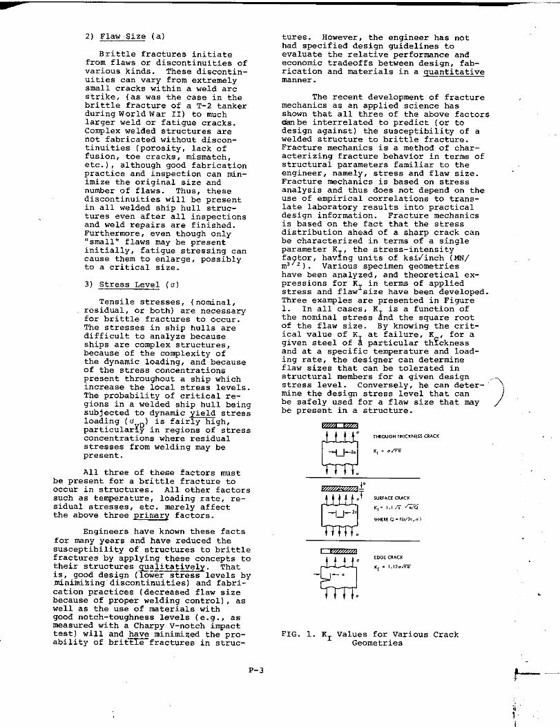
The recent development of fracturemechanics as an applied science hasshown that all three of the above factorsb be interrelated to predict (or todesign against) the susceptibility of awelded structure to brittle fracture.Fracture mechanics is a method of char-acterizing fracture beha”ior in terms ofstructural parameters familiar to theengineer, namely, stress and flaw size.Fracture mechanics is based on stressanalysis and thus does not depend on theuse of empirical correlations to trans-late laboratory results into practicaldesign information. Fracture mechanicsis based on the fact that the stressdistribution ahead of a sharp crack canbe characterized in terms of a singleparameter K1, the stress-intensityfa~tor, hav~ng units of ksi/inch (f4w/m3 2). Various specimen geometrieshave been analyzed, and theoretical ex-pressions for K1 in terms of appliedstress and flaw size have been developed.Three examples are presented in Figure1. In all cases, K1 is a function ofthe nominal stress and the square rootof the flaw size. By knowing the crit-ical value of K1 at failure, K , for agiven steel of a particular th~cknessand at a specific temperature and load-ing rate, the designer can determineflaw sizes that can be tolerated instructural members for a give” designstress level. Conversely, he can deter-mine the design stress level that canbe safely used for a flaw size that maybe present in a structure.
a
.,WWG” ,H,c.wsCRACK
++. K,- ./=
““’”-’\
)
FIG. 1. K1 values for various CrackGeometries
.
P-3
I I.. .,
—.. s.,1. —
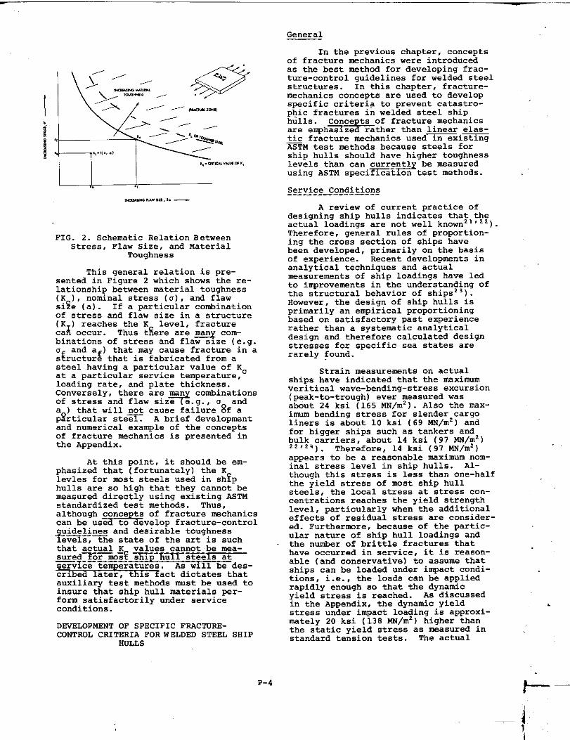
FIG. 2. Schematic Relation BetweenStress, Flaw Size, and Material
Toughness
This general relation is pre-sented in Figure 2 which shows the re-lationship between material toughness(K ), nominal stress (u), and flawsise (a). If a particular combinationof stress and flaw size in a structure(K1 ) reaches the K level, fracturecan occur. Thus t~ere are ~ com-binations of stress and fla” size (e.g.
“Eand ~f) that may cause fracture in a
s ructure that is fabricated from asteel having a particular value of Kcat a particular service temperature,loading rate, and plate thickness.Conversely, there are man combinationsof stress and flaw .izfi.9., . anda ) that will gt cause failure 8fap~rticular steel. A brief developmentand numerical example of the conceptsof fracture mechanics is presented inthe Appendix.
At this point, it should be em-phasized that (fortunately) the Klevles for mst steels used in sh?phulls are so high that they cannot bemeasured directly using existing ASTMstandardized test methc”ls. Thus ,although concepts of fracture mechanicscan be used to develop fracture-controlguidelines and desirable toughness-.—Ie=s, the state of the art is suchthat actual x values cannot be mea-sured~is? ~p-fi~l~~~~els atservice temperatures.~des-cribed later, this fact dictates thatauxiliary test methods must be used toinsure that ship hull materials per-form satisfactorily under serviceconditions.
DEVELOPMENT OF SPECIFIC FRACTURE-CONTROL CRITERIA FOR WELDED STEEL SHIP
HULLS
General—-
In the previous chapter, conceptsof fracture mechanics were introducedas the best method for developing frac-ture-control guidelines for welded steelstructures. In this chapter, fracture-mechanics concepts are used to developspecific criteria to prevent catastro-phic fractures in welded steel shiphulls . Conc~of fracture mechanicsare e~h~zed rather than linear elaS-tic fracture mechanics used~xi~=TM test nethcds because steels forship hulls should have higher toughnesslevels than can currently be measuredusing ASTM speci=a+=n test methods.
Service Conditions-_-_---—— ---—---
A review of current practice ofdesigning ship hulls indicates that theactual loadings are not well knownz 1‘22).Therefore, general rules of proportion-ing the cross section of ships havebeen developed, primarily on the basisof experience. Recent developments inanalytical techniques and actualmeasurements of ship loadings have ladto improvements in the understanding ofthe structural behavior of shipsz 3).However, the design of ship hulls isprimarily an empirical proportioningbased on satisfactory past experiencerather than a systematic analyticaldesign and therefore calculated designstresses for specific sea states arerarely found.
Strain measurements on actualships have indicated that the nIAximumveritical wave-bending-stress excursion(peak-to-trough) ever measured wasabout 24 ksi (165 NN/m2 ). Also the max-imum bending stress for slender cargoliners is about 10 ksi (69 WN/m2 ) andfor bigger ships such as tankers and:y+:~carriers, about 14 ksi (97 NN/m2 )
). Therefore, 14 ksi (97 NN/m2 )appears to be a reasonable maximum nom-inal stress level in ship hulls. Al-though this stress is less than one-halfthe yield stress of most ship hullsteels, the local stress at stress con-centrations reaches the yield strengthlevel, particularly when the additionaleffects of residual stress are consider-ed. Furthermore, because of the partic-ular nature of ship hull loadings andthe number of brittle fractures thathave occurred in service, it is reason-able (and conservative) to assume thatships can be loaded under impact condi-tions, i.e. , the loads can be appliedrapidly enough so that the dynamicyield stress is reached. As discussedin the Appendix, the dynamic yieldstress under impact loading is approxi-mately 20 ksi (13S MN/mz ) higher thanthe static yield stress as measured instandard tension tests. The actual
.
P-4 h–––
{ ,.I
loading rate for ship hulls is prob-ably between the limits of “static”lo2ding strain rate approximately
-!10 ‘sec ) and dynamic or impactloading (strain rate approximately10 sec l). However, in view of thegeneral service behavior of ships, andthe lack of information on specificloading rates, the conservative assump-tion that ships are loaded dynamicallyis made.
It should be emphasized that the.— .-—naterid toumness requirements devel-oped in this report would be changedsignificantly if an “intermediate”loading rate-were assumed for shiphull structures rather than a dynamicloading rate. For purposes of compar-ison, bridge structures are assumed tobe loaded at an intermediate loadingrate and their material toughnessrequirements arc less stringent thanthose developed in this paper.
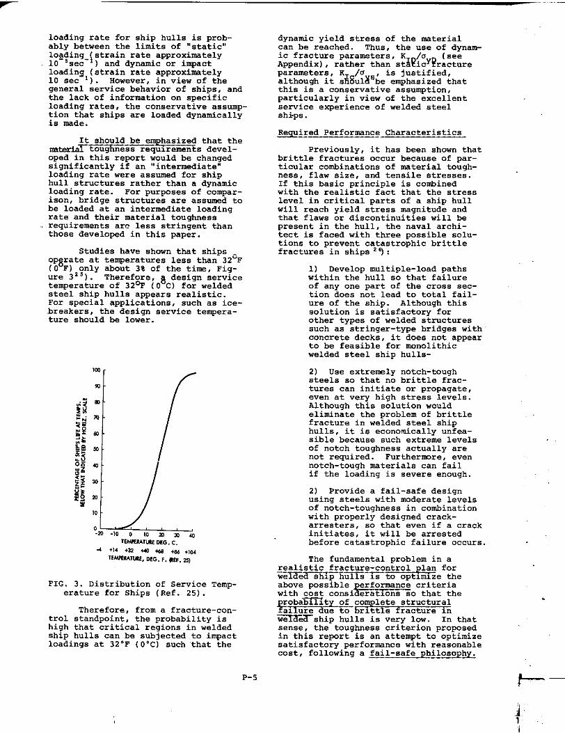
Studies have shown that shipsOp~rate at temperatures less than 32°F(O F) only about 3% of the time, Fig-ure 325). Therefore, ~ design servicetemperature of 32% (O C) for weldedsteel ship hulls appears realistic.For special application, such as ice-breakers, the design service tempera-ture should be lower.
m
mI f
10I/
FIG. 3. Distribution of Service Temp-erature for Ships (Ref. 25).
Therefore, from a fracture-con-trol standpoint, the probability ishigh that critical regions i“ weldedship hulls can be subjected to impactloadings at 32”F (O“C) such ‘that the
dynamic yield stress of the materialcan be reached. Thus, the use of dynam-ic fracture parameters, K /o (seeAppendix) , rather than st~~icy?ractureparameters, K /0
Ais justified,
although it s ~ultis;e emphasized thatthis is a conservative assumption,particularly in view of the excellentservice experience of welded steelships .
*izsL=?-~2csa=mis
Previously, it has been shown thatbrittle fractures occur because of par-ticular combinations of material tough-ness, flaw size, and tensile stresses.If this basic principle is combinedwith the realistic fact that the stresslevel in critical parts of a ship hullwill reach yield stress magnitude andthat flaws or discontinuities will bepresent in the hull, the naval archi-tect is faced with three possible solu-tions to prevent ca2t,astrophicbrittlefractures in ships ):
1) Develop multiple-load pathswithin the hull so that failureof any one part of the cross sec-tion does not lead to total fail-ure of the ship. Although thissolution is satisfactory forother types of welded structuressuch as stringer-type bridges withconcrete decks, it does not appearto be feasible for monolithicwelded steel ship hulls-
2) Use extremely notch-toughsteels so that no brittle frac-tures can initiate or propagate,even at very high stress levels.Although this solution wouldeliminate the problem of brittlefracture in welded steel shiphulls , it is economically unfea-sible because such extreme levelsof notch toughness actually arenot required. Furthernmre, evennotch-tough materials can failif the loading is severe enough.
2) Provide a fail-safe designusing steels with moderate levelsof notch-toughness in combinationwith properly designed crack-arresters, so that even if a crackinitiates, it will be arrestedbefore catastrophic failure occurs.
The fundamental oroblem in a~~~istic fracture- con~rol plan for—- —-—welde~~p hulls IS to optimize theabove possible performance criteriawith cost consideratmns so that the
%~~j~d~l~brittle fractur~nroba~lt of complete structural
welded ship hulls is very low. In thatsense, the””toughness criterion proposedin this report is an attempt to optimizesatisfactory performance with reasonablecost, following a ~ai l-safe philosophy.
.
P-5 &._–
]

Thus, the third solution, na~e~ythe us~~f~afid weldments with~ate levels of notch toughnessc~-tiined-with properly designedcrack arresters, is recommended as a~rXTt~r;-—cXtZ?l_Oii-?Gir-wZiFeZ<Q—hu~—____
In line with this general frac-ture-control plan, the followingitems are noted.
1) As has been well documentedduring the past 30 years, thedefinite passability of brittlefracture in welded ship hullsexists because welded ship hullsare complex structures that canbe subjected to local loading ofyield point magnitude at temper-ature as low as 32-F (O”C) . Theassumption of dynamic loadingis made to be conservative andbecause ships are generallysingle-load path structures.That is, if a fracture initiates,it will continue to propagateunless arrested, because thestructure is continuous aroundthe hull.
2) Because of current limita-tions in fabrication practice andinspection at shipyards, a largeprobability exists that large un-detected flaws (e.g. , equal tO %the plate thickness) will bepresent at some time during thelife of welded ship hulls. Even%7iti’’improvenentsin control ofwelding quality during fabrica-tion, some discontinuities willstill be present prior to theservice life of the structureand fatigue may cause thesediscontinuities to grow in sizeduring the life of the structure.Thus, it is assumed that flawsare present in all welded shiphulls.
3) The naval architect generallydoes not have absolute controlover the fabrication of a weldedship hull. Thus, he should es-tablish material and @~i~n con-trols during the design processthat are adequate to prevent theoccurrence of brittle fracturesin welded ship hulls. Althoughthe designer tries to avoid de-tails that act as stress raisers,this is an impossible task inlarge complex welded structures.Hence, the emphasis in thisfracture-control plan is on thechoice of proper materials (tough-ness specifications for steelsand weldments ) and design (properuse of crack arresters) , eventhough quality fabrication andinspection of ~elas are extreme-ly important.
4) Although specifying solelythe metallurgy and manufacturingprocess, including composition,aeoxidi zation practice, heattreatment, etc. , has been onemethoa of controlling the levelof notch toughness in a steel,the only method of measuring theactual toughness of a steel is atoughness ~~. A direct measureof toughness woula appear to bebetter for the user because heis ultimately concerned with theperformance of the steel or weld-ment, and this performance canbest be determined by a notch-toughness test. Also a Specifi-cation based on a notch-toughnesstest would appear to be nmreequitable for staelmakers in thatit leaves them some latitucle toadopt the process best suites totheir particular operation insatisfying the toughness require-ment. However, a toughness testdoes have the clisaavantage in thata test value pertains to only onelocation in a plate whereas properprocessing control shoula pertainto the entire plate. However, be-cause this may not always be true,a toughness test is no less effec-tive as an indication of theservice performance of the entireplate.
5) Because of the aifficultiesin conducting a toughness teston a composite weldment, notch-toughness specimens shoulcfbetaken from each of the followingregions : base metal, weld metal,and heat-affected zone. Whilethere is no “one” heat-affected-zone, an average measure oftoughness can be obtainecl bynotching the test specimen sothat the tip of the notch isapproximately at the center ofthe heat-affected-zone region.Existing AES Rulesz’ ) specifythat five sets of in@act speci-mens be taken during welding Pro-cedure Qualification Testing forweldments “sec3 for very low-temp-erature service. Tbe notches forthe specimens are locatea at thecenterline of the weld, on thefusion line, and in the beat-affected-zone, 0.039-in (1 mm) ,0.118-in (3 mm) , ancf 0.197-in(5 nun)from the fusion line. Forweld qualification tests it may hedesirable to follow this practice,although this practice may bequite expensive for normal qualitycontrol . .
The specific requirements to im-plement these fail-safe fracture-controlguidelines consist of 1) establishing asatisfactory level of notch toughness
P-6 F--
in the steels and weldments, and2) developing of properly designedcrack arresters. These requirementsare presented in detail in SSC Report244. It should be re-emphasizedthat improper fabrication can stilllead to structural failure regardlessof the level of notch-toughness. Thusgood quality welding and inspectionpractices must be followed.
MATERIALS PERFORMANCE CHARACTERISTICS
General———
In general, the primary load-carrying members of steel ship struc-tures are the plate members within thecenter .4L of the hull that comprisethe upper deck, bottom shell, sideplating, and longitudinal bulkheads.Because these members are the primaryload-carrying members, materialtoughness requirements should bespecified for them. Although stiffen-ers can also be primary load-carryingmembers, they are not connected toeach other and thus failure of onestiffener shodd not lead to failweof adjacent stiffeners. Therefore,they need not be subject to the pro-posed criteria.
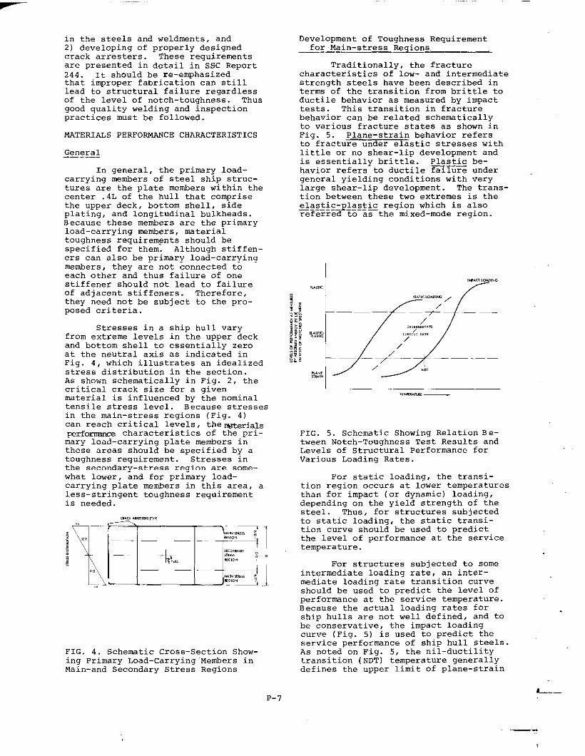
Stresses in a ship hull varyfrom extreme lem?l$ in the upper deckand bottom shell to essentially zeroat the neutral axis as indicated inFig. 4, which illustrates an idealizedstress distribution in the section.As shown schematically in Fig. 2, thecritical crack size for a givenmaterial is influenced by the nominaltensile stress level. Because stressesin the main-stress regions (Fig. 4)can reach critical levels , the ~wial~perfonmnce characteristics of the pri-mary load–carrying plate metiers inthese areas should be specified by atoughness requirement. Stresses inthe secondary-stress region are some-what lower, and for primary load-carrying plate members in this area, aless-stringent toughness requirementis needed.
a,,,..,,,,,,m,,
~y;~~%~~;
,.
FIG. 4. Schematic Cross–Section Show-ing Primary Load-carrying Members inMain-and Secondary Stress Regions
Development of Toughness Requirementfor Main- *tzress Regions
Traditionally, the fracturecharacteristics of 10”- and intermediatestrength steels have been described interms of the transition from brittle toductile behavior as measured by impacttests. This transition in fracturebehavior can be related schematicallyto various fracture states as shown inFig’. 5. Plane-strain behavior refersto fracture under elastic stresses withlittle or no shear-lip development andis essentially brittle. Plastic be-havior refers to ductile failure undergeneral yielding conditions with verylarge shear-lip development. The trans-tion between these two extremes is theelastic-p~$g~~g region which is also———. ._—referred to as the mixed-mode region.
,W.a LW, NG
~.TW,F.,., .
FIG. 5. Schematic Showing Relation Be-tween Notch-Toughness Test Results andLevels of Structural Performance forVarious Loading Rates.
For static loading, the transi-tion region occurs at lower temperaturesthan for impact (or dynamic) loading,depending on the yield strength of thesteel. Thus, for structures subjectedto static loading, the static transi-tion curve should be used to predictthe level of performance at the servicetemperature.
For structures ?,”bjected to someintermediate loading rate, an inter-mediate loading rate transition curveshould be used to predict the level okperformance at the service temperature.Because the actual loading rates forship hulls are not well defined, and tobe conservative, the impact loadingcurve (Fig. 5) is used to predict theservice performance of ship hull steels.As noted on Fig. 5, the nil-ductilitytransition (NDT) temperature generallydefines the upper limit of plane-strain
L---P-7

under conditions of -t loading.
I
ITEm.,.,, —
FIG. 6. Schematic Showing Relation Be-tween Level of Performance as Measuredby Impact Tests and ND!Cfor 3 ArbitrarySteels.
A fundamental question to be re-solved regarding a fracture criterionfor welded ship hull steels is: ‘Whatlevel of material performance should berequired for satisfactory performancein a ship hull subjected to dynamicloading?-’ That is, as shown schemati-cally in Fig. 6 for impact loading, oneof the following three general levelsof material performance must be estab-lished at the service temperature forthe steels that are primary load-carry-ing members:
1) Plane-strain behavior - Usesteel (1) - Fig. 6
2) Elastic-plastic behavior -Use steel (2) - Fig. 6
3) Fully plastic behavior - Usesteel (3) - Fig. 6
Although fully plastic behaviorwould be a very desirable level ofperformance for ship hull steels, itmay not be necessary, or even economi-cally feasible. A reasonable level ofelastic-plastic behavior (steel 2 -Fig. 6) should be satisfactory to pre-vent initiation of mst brittle frac-tures. (If fractures do initiate,they should not lead to catastropbi cfailure of a ship as long as properlydesigned crack arresters are used. )Specifying that the NDT temperature ofall steels and weldments used in pri-marv load-carrvina members in thecen~er O.4L of- ships be equal to orless than O°F (-18”C) (32° F (18°C)below the minimum service temperature)should establish the required perform-ance level, if the materials followthe aenerai behavior of steel 2 in
Thus, the recommended primarymaterial specification in an overallfracture-control plan for weldedsteel ship hulls is that all steelsand weldments used in primary load-carrying plate members in the mainstress regions of ships have a maximumNDT of O“F (-18”c) as measured by ASTMTest Method E-208-692’ ).
Although necessary, this primaryNDT requirement alone is not sufficient,since an additional toughness require-ment is necessary to insure that theresistance to fracture of the steelsand weldments whose NDT is O-F (-18”c)(or lower) is actually satisfactory at32”F (O-C). That is, this additionalrequirement is necessary to guaranteethat materials follow the general per-formance level shown in Fig. 6, ratherthan exhibit a low-energy shear behavior.Fig. 7 shows the relationship of low-energy performance to normal behaviorand very-high level behavior (HY-80type behavior for military applications) .
~ /-””-’’”
I,, ,,
,,M.,U,,, ,,.. ,
FIG. 7. Schematic Showing Relation Be-tween Normal-, High-, Low-Energy ShearLevels of Performance as Measured byImpact Tests.
Low-energy shear behavior usuallydoes not occur in low-strength steelsbut is sometimes found in high-strengthsteels, i.e. , steels having yieldstrengths approaching 100 ksi. Thusthe additional toughness requirementis necessary to eliminate the possibil-ity of low-energy shear failures, pri-marily in the higher-strength steels.
In terms of fracture-mechanicsconcepts, the critical dynamic tough-ness, K1 , is approximately equal tO0.60 a? NDT, where a is the d~u$cyiel~Dstrength of the ~terial.for the ship hull materials that satis-fy the criterion that NDT be equal toor less than O“F (-18”c) ,
Fig. -6.
P-8

‘ID .r - 0.6 at O“F (-18-C)yD
At the32-F (O”C)
KID
~ 1syD
minimum service temperature of
estimated to be about O.9
because of the rapid increase in KIDwith temperature in the transitiontemperature region. Although thevalue of O.9 cannot be establishedtheoretically, ewerimental resultsfOr variOus SteelS2’ ), including ABS-Cand ASTM A517 steels, Figures 8 and 9,indicate that this is a realistic value.
,., r ?/7
FIG. 8. Crack-Toughnessfor 7=B5-C Steel
Performance
It should be emphasized that al-though concepts of fracture mechanicshave been used to develop an auxiliarytoughness requirement that K /ofor l-inch-thick (25.4 mm) pf~te~~,z 0”9materials satisfying this criterion willexhibit elastic-plastic, ~-plane-strain behavior. Therefore, this tough-ness le”el _ be measured usingexisting state-of-the-art fracture-mechanics tests as specified by ASTMa 0).That is, for l-inch-thick (25.4 mm)plates, the upper limit of dynamicplane-strain behavior is
‘ID1.0 = 2.5 (—)2
‘yD
Or KID/uyD = O.63. Thus NDT (where
KID/oyD z O.6) is the upPer limit of
dynamic plane-strain behavior for 1-inch-thick (25.4 mm) plates.
At 32-F (O”C), K /m is speci-fied in this criterionl?o ~~ 0.9,which is beyond the limits of dynamicplane-strain behavior for l-inch-thick(25.4 mm) plates.
For 2-inch-thick (50.8 nun)plates,
‘ID2.0 = 2.5 (7)2
yD
R ;+9<:xgt;a!A8:ei:vR:. liR:s:fad;:am-inch-thick (50.8 nun)plate, loadeddynamically to the full yield stress ofa material in the presence of a sharpflaw at 32°F (O“c) would be at thelimit of dynamic plane-strain beha”ior.B ecause the Drobabilitv of all thesefactors occuking simul~aneously is min-imal, the req”irernent that K~D/.yD to. 9
aPPears tO be satisfactory for all thick-
TT
nesses of plate 2 inches (50.8 mm) or
/1
less . However, the required toughnesslevels for plates thicker than 2 inches
/1 ; (50.8 mm) should be increased.
Using concepts of fracture mech-anics, as well as engineering experi-ence, the following observations can bemade regarding the level of performanceat 32 F“(O“C) for steels and weldmentsthat satisfy the ~imar toughness re-quirement of ND. f ~-18°C) and the~u~il~g~ toughness requirement thatKID~uyD ~ 0.9 at 32°F (O°C) :
I 1, Im .M -m .,. .,m .a . . ,m
,,s! ,,mlA,uJ %
FIG. 9. Crack-Toughness Performancefor A517-F Steel
1) The start of the transitionfrom brittle to ductile be-havior wil 1 begin ~w theminimum ser”ice temperatureof 32” F (O-C). Therefore, atthe minimum service tempera-ture, the materials will ex-hibit some level of elastic-plastic non-plane-strain be-
P-9 L---
-
havior in the presence of asharp crack under dynamicloading.
2) Although not specified in theproposed toughness require-ment, the materials will ex-hibit some percentage offibrous fracture appearanceat 32”F (O”C). Service ex-perience has shown that frac-ture appearance is an effec-tive indicator of the resis–tance to brittle fracture.Thus, this criterion isconsistent with serviceexperience of ship hulls.
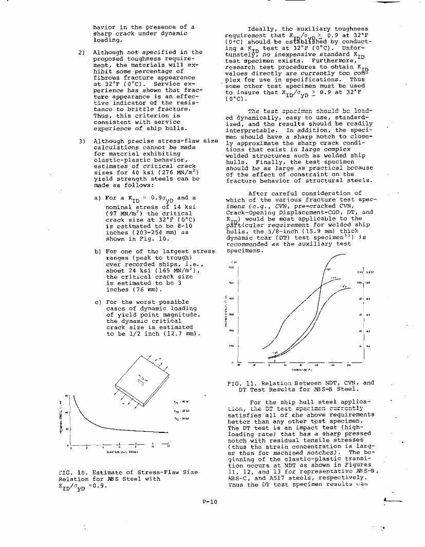
3) Although precise stress-flaw scalculations cannot be madefor material exhibitingelastic-plastic behavior,estimates of critical cracksizes for 40 ksi (276 NN/m2)yield strength steels can bent+deas follows:
ize
a)
b)
‘or a ‘ID = ‘“goyDand a
nominal stress of 14 ksi(97 MN/m’) tbe criticalcrack size at 32°F (O”C)is estimated to be 8-10inches (203-254 nun) asshown in Fig. 10.
For one of the larqest stressranges (peak to tr~ugh)ever recorded ships, i;e.,about 24 ksi (165 MN/m ),the critical crack sizeis estimated to be 3inches (76 mm) .
c) For the worst possiblecases of dynamic loadingof yield point magnitude,the dynamic criticalcrack size is estimatedto be 1/2 inch (12.7 nun).
.,, .,,,
.,,. ..)
x,,.b!
CIG. 10. Estimate of Stress-Flaw SizeRelation for ?SS Steel withKID/OyD =0.9.
P-lo
Ideally, the auxiliary toughnessrequirement that K /0 > 0.9 at 32SF(O‘c) should be es~~bl~~h~d by ~~-t-ing a KID test at 32-F (O-C) .tunately’, no inexpensive standard K.,.test sD&2imen exi; ts. Furthermore, ‘“resear;h test procedures to obtain” KIDvalues directly are currently too com-plex for use in specifications. Thussome other test soecimen must be usedto insure that K1~/’JyD z O. 9 at 32°F(o”c).
The test specimen should be load-ed dynamically, easy to use, standard-ized, and the results should be readilyinterpretable. In addition, the speci-men should have a sharp notch to close-ly approximate the sharp crack condi-tions that exist in large complexwelded structures such as welded shiphulls. Finally, the test specimenshould be as large as practical becauseof the effect of constraint on thefracture behavior of structural steels.
After careful consideration ofwhich of the various fracture test spec-imens (e.g. , CVN, pre-cracked CVN,crack-opening Displacement-COD, DT, andKID) would be most applicable to thepart~cular requirement for welded shiphulls, the 5/8-inch (15.9 mm) thickdvnamic tear (DT) test sPecimen3 ‘) is.;commendedspecimens.
as the auxil;ary test
f
,!
/Y-,,.,
,/ ‘ //T
“ /
‘ ,///
FIG. 11. Relation Between NDT, CVN, andDT Test Results for A9S-B Steel.
For the ship hull steel applica-tion, the DT test specimen currentlysatisfies all of the above requirementsbetter than any other test SPeCiMen.The DT test is an impact test (high-loading rate) that has a sharp pressednotch with residual tensile stresses(thus the strain concentration is larg-er than for mchined notches) . The be-ginning of the elastic-plastic transi-tion occurs at NDT as shown in Figures11, 12, and 13 for representative XlS-B,ABS-C, and A517 steels, respectively.Thus the DT test specimen results can

be easily related to the NDT valuesfor ship steels.
If the loading rates for shipswere shown conclusively to be inter-mediate or slow, and if less conserv-atism were desired, then the DT testmight not be the test that nwst closelymodels the structural behavior of shiphull steels. However, for the assump-tion of dynamic loading in the presenceof a sharp crack it does mgdel the be-havior better than any other specimen.
.a’,Lm. .,. .,=,. ,,,
FIG. 12. Relation Between NDT, CVN, andDT Test Results for ABS-C Steel.
+-t x“””
H-4’, ““rI J . ..
—— ,Le.1. . . .. 0 . !. ,. ... ..O .,. . . ..7,..., ””,,% ,,..., ”,,,.,
FIG
KIC ‘
were
13. Relation Bet”een NDT, CVN, DT,
and ‘ID for A517 steels.
If the loading rates for shipsshown conclusively to be inter-
mediate or s1o”, and if less conserva-tism were desired, then the DT testmight not be the test that most close-ly models the structural behavior ofship hull steels. However, for theassumption of dynamic loading in thepresence of a sharp crack, it doesmodel the beha”ior better than anyother specimen.
For the plate thicknesses nor-mally used in ship hull construction(less than 2-inches (50.8 mm) thick) ,thickness has a second-order effecton the toughness behavior in the trans-ition temperature region compared with
the first-order effects of loading rateand notch acuity. Increasing the load-ing rate of notched steel specimensraises the transition temperature asshown in Fig. 8 and 9 ,9 . Increasingthe notch acuity (from that in a mach-ined CVN specimen to that in a pressed-notch DT specimen) also raises the be-ginning of the transition temperaturerange as shown in Fig. 11-13 and 26-29.The second-order effect of thickness(namely the very small change in trans-ition behavior between 5/8 (15.9 mm)and 1 inch (25.4 mm) thick DT specimens)is shown in Figs. 11, 12, and 13. Thereare lar~r changes in transition temper-atur~~or much thicker plates (e.g. ,3-to 12-inch (76 to 305 mm) thick platesused in thick-walled pressure vessels)but for the ship hull application(plates less than 2-inches (50.8 mm)thick) , the effects of specimen thick-ness are second order and.can beignored.
Therefore, although it weuld betechnically more desirable to we full-thickness DT specimens to specify thebeha”ior of ship steels, only the 5/8-inch (15.9 nun) thick DT specimen isbeing recommended because the practicalaspects of testing the S/E-inch (15.9mm) thick DT specimen far outweigh thedisad”antaqe of ha”ing to use a lessthan full-plate thickness test specimen.The 5/8-inch (15.9 nun)DT specimen hasrecently been standardized (MIL Stan-dard lr5013 1)--also see Appendix C) and
can be conducted in existing NDT typefalling-weight test machines or inrelatively small pendulum type machines.
For abeve reasons, the DT test isrecommended as the auxiliary test speci-men to be used to insure that elastic-plastic behavior is actually being ob-tained in steels and weldments forwelded ship hulls even though CVN im-pact test results currently are widelyused as reference values for predictingthe behavior of ship steels. Becauseof the wide-spread use of CVN test re-sults, particularly in quality control,CVN mlues that axe equivalent to DTtest “al”es are presented in Appendix E.
After having selected the DT testspecimen as the auxiliary test specimen,the next step is to establisb the DTvalue at 32”F (O“C) that will insure ap ratio of O.9 so that the desiredlevelygf elastic-plastic behavior isobtained for all steels and weldments.Bec.a”se there are no direct theoreticalsolutions to establish the DT valuescorresponding to K /0 = 0.9, empiri-cal considerations l~rey~sed.
A review of available experimentaltest results indicates that at NDT,where K /a = O.6t the amount ofabsorbe&Den~~gy for 5/8-inch (15.9 nun)
L. .
P-n

thick DT specimens iS apprOXi~telYabsorbed energy for the DT specimenscan be approximated by (O.9/0.6) times100, or equal to 150 ft lb (203J) . Thegeneral relation between K and energyin the elastic region WOU1~ indicatethat this ratio should be squared.However, in the elastic-plastic region,where the absorbed energy is increasingvery rapidly with temperature, a linearrelation 1M% be nwre realistic. Thevalue of 150 ft lb (203J) is relativelysmall and, therefore, it is recommendedthat the DT test be conducted at 75°F(24”c) (room temperature) rather than32”F (O“C) because it may be difficultto measure a significant change inresistance to fracture between O°F(-18”C) (limit of plane-strain behavior)and 32°F (O“C) (a moderate level ofelastic-plastic behavior) . Althoughfrom a technical viewpoint it would bePreferable to conduct the DT test at~h 32°F (O”C) and 75°F (24”c) , thepractical considerations of the speci-fication suggest that the DT test be
conducted at +75-F (24”c) (room temper-ature ).
If the test is conducted at 75.F(24”c) , the minimum K /0should be 1.5 on the *~si~Do~~non-linear extrapolation from 0.9 at 32°F(O“C)as shown in Fig. 14. Thus, theminimum DT value should be (1.5/0.9)times 150, or equal to 250 ft lb (339J)Fig. 14 also shows a schematic repre-sentation of the lower-bound sDecifi-cation curve of ~uired Valuei (NDT =O-F (-18”C) and K1 ~. 1.5 at 75-F(24”c) - actually ~50y$’t lbs (339J)in a DTtest) and-the mininmm desiredvalues of K /0 = 0.9 at 32°F (O”C)compared wi~~ pX&’sible curves for shipsteels that either do or do not meetthe criterion. This figure showsthat by meeting both of the toughnessrequirements at O°F(-18-C) and 75-F(24”c) the desired bebavior at 32°F(O“C) (KID/ayD z 0.9) should be met.
t!!l .- w
“.. 6.. . . .,,,#!..,E,....
FIG. 14. Schematic Showing the RelationBetween Proposed Toughness Criterionfor Members in the Main-Stress Regionand Behavior of Actual Ship Steels.
P-
Assuming that the dynamic yieldstrength is approximately 20 ksi (138MN/m2 ) higher than the static yieldstrength of a steel (Appendix) , thereauired DT values at 75°F (24-C). .K /o > 1.5) can be proportioned fors~~ent?b-level as shown in Table 1.This adjustment is necessary to insurethat hiuh strenuth steels have the samerelativ; toughn; ss levels as lowerstrength steels.
Thus, the recommended auxiliarymaterial specification in an overallfracture-control plan for welded steelship hulls is that all steels and weld-ments used in primary load-carryingplate members in the main-stress regionsof ships exhibit the levels of absorbedenergy in a 5/8-inch (15.9 nun)dynamictear (DT) specimen as presented inTable 1.
The values presented in Table 1should be the minimum values of speci-mens oriented in the same direction asthe printmy stress level (notch orient-ed perpendicular to the direction ofprirre.rystress) . In most cases, thespecimens will be longitudinal to therolling direction. However, if thetransverse stress level becomes signif-icant, then the test specimens shouldbe oriented in the transverse direction
It should be emphasized that thevalues presented in Table 1 are ~tfully plastic “shelf-level” values,but rather, are values that should in-sure the desired level of elastic-plastic behavior.
Development of Toughness Criterion fOrSecondary-Stress Regions————_——
The toughness criteria developedthus far in this section are applicableto areas of maximum stress levels whichinclude critical members in the main-stress regions of the hull. Stiffenersand web frames probably do not need thesame level of toughness as the mainplating because of their discontinuousnature. Primary load-carrying memberswithin the secondary-stress region(Central D/2 portiOn-Fig. 4) will nowbe considered.
In this vicinity, nominal stressescan usually be expected to be less thanone-half tbe maximum normal hull stressin the deck. Because low stresses (5to 8 ksi (34 to 55 MN/mz) ) have beenknown to initiate brittle fractures insteels at temperatures less than NDT5 ),and flaws are present in ships, itaccordingly follows that a moderatenotch-toughness criterion is requiredeven in secondary-stress regions ofprimary load-carrying metiers.

TASLE 1
Dynamic Tear (DT) Requirements at +75-F (24”c) for Steels and Weldments in Main-Stress Regions for Primary Load-Carrying Members* of Ship Hulls
——____Actual Static Assumed Dynamic —-——P~p~~i6fiali ty
.—
YieldAbsorbed Energy —
Yield Strength factor for Requirements* ● forStrength Level 5/8-inch (15.9 mu)
Oys ‘yD thick specimens
ksi NW/mz ks i NN/m2 ft-lb— _________________ J-— _____________________________
40 276
50 345
60 414
70 483
80 552
90 621
100 689
60 414 ( 60/60) 250 339
70 483
80 552
90 621
00 689
10 758
20 827
70/60) 290 393
80/60) 335 454
90/60) 375 508
100/60) 415 563
110/60) 460 624
120/60) 500 678
* These members must also meet the requirement of NDT z O“F (-18°C)
● * Dynamic elastic-plastic behavior approximating K /0—- —____
~uD = 1.5-— ________________ ___
Because the same size flaws canexist throughout the entire bull sec-tion, the toughness criterion for thesecondary stress regions should resultin the same required stress-intensityfactor (K ) for both primary-and-
lQsecondary- tress regions. Thus , forthe main-stress region, KID.adac= and
for the secondary- stress region, KID.0/2 da A comparison of theserelati~~~ shows that the required KIDfor the secondary-stress region isone-half that of the main-stress region.Accordingly, the required KID/a
~~ee%~- ~r~; ~5r$~L~YRis 0.3Df=t10However,
a history of welded steel fracturesindicates that a design for thisparticular level of toughness (.NDT)would IIDt be desirable because frac-tures have initiated from very smallflaws when service temperatures arelower than NDT, even when the appliedstresses were quite 10W5 ).
Thus, even though a tolerableflaw size can be numerically computedfOr a KID/oyD ratiD of O.45, it would
be very small (.0.1 inch (2.5 mm)),and a minimum service temperature coin-cident with NDT (KID/~ = O.6) appearsto be the lowest reall~~ic design-toughness level. A graphical repre-sentation of this design-toughnesslevel is presented in Figure 15.
A review of several hull crosssections indicates that primary load-carrying members in the secondary-stress regions usually have nominal-section thicknesses less than or equalto one inch (25.4 nun)’s). This is dueto the fact that the steel in thesemembers is seldom a higher grade than2E?S Grade B , which is restricted by~S rule,’=) to a one-inch (25.4 mm)
P-13
thickness for this application. Thusa one-inch (25.4 nun) section thicknesswould appear to be the maximum thick-ness used. As mentioned previowly,NDT essentially represents the upperlimit of plane-strain behavior for thisthickness.
e~,‘,, “&..
‘\\ “\\\ ‘.,%”,
..:: ,,,h,a”‘\\‘-%,, -%-..----:,, .. .,,- .,;.,,* --------~.. -
K,. ., . . . (m.. s,..1., r. ?!..,
------_______
w 0..s .,. ,m..)..:,:,,7,..-..
),, ,,6, , $ $, ,, ,,
,m.w,Iz, ,,.,, ,., ”,,
FIG. 15. Schematic Comparison of Main-Stress and Secondary-Stress Criterion
Becawe the material-toughnessrequirement of K /0
ID yD = 0.6 at the
minimum service temperature (32‘F(O“C))is coincident with the NDT temperature,it can be conveniently established byusing the NDT test. Such a marginaltoughness level does not require anauxiliary test to evaluate transitionbehavior. However, past experiencewith the NDT testing procedure indicatesthat a margin of at least 10”F (6“c) be
allowed, particularly for a specifica- 5)tion that is based solely on NDT. Forall practical purposes, an NDT temper-ature of 20”F (-7”c) should be sufficient toassure that KID/ayD = 0.6 at 32”F (O”C). 6)
Thus, it is recommended that allsteels and we!ldments used in pritiryload-carrying plate members in thesecondary-stress regions must satisfya less stringent material–toughnessrequirement of NDT : 20° F (-7”C) .
As stated previous lY, tbe abovematerial specifications for either themain-stress regions or the secondary-stress regions will not guarantee thecomplete absence of brittle fracturesin welded ship hulls. Therefore, afail-safe philosophy that incorporateproperly designed crack arresters fab-ricated from steels with very highlevels of notch toughness should beused in conjunction with the abovematerial requirements. Ho”ever, thesematerial-toughness requirements shouldresult in rational fracture-controlguidelines that will minimize the prob-ability of brittle fractures in weldedship hulls consistent with economicrealities.
ACKN~ LEDGMEN~——. —
This paper is based on the workconducted as part of Project SR-202,“Fracture Criteria” under NSEC ContractNo. NOO024-72-C-5316. The Final Reporton that project was Fracture-ControlGuidelines for Welded Steel Ship Hulls——— —— ___ .——by S. T. Rolfe, D. M. Rhea, and B. O.Kuzmanovic published in 1974 as ShipStructure Committee Report SSC-244.
BEFEPSNCES
1] Bannerman, D.B . & Young, R. T.,“Some Improvements Resulting fromStudies of Welded Ship Failures” ,Welding Journal, Vol. 25, No. 3,March 1946.
2) Acker, H.G., “Review of WeldedShip Failures” (Ship StructureConnnittee Report Serial No. SSC-63), Washington: National Academyof Sciences-National ResearchCouncil, December 15, 1953.
3) Final Rep~r~ of a Board of lnves-—--—- .——tigation - The Desi~and Methods-————of construc~l~~=~w elded Steel—--—-——-————————Merchant Vessels, 15 July, 1946,i%~~riiiiii~t-P~ting Press, Washing-ton, D. C., 1947.
4) Boyd, G.M., & Bushell, T.W. ,“Hull Structural Steel – The Uni-fication of the Requirements ofSeven Classification Societies” ,Quarterly Transactions: The~~~Institution of Naval ?+rchi~e=ts—-———
7)
8)
9)
10)
11)
12)
13)
14) .
15)
16)
Parker, E.R., “Brittle Behavior ofEngineering Structures” , New York -John Wiley & Sons, Inc. , 1957
Turnbull, J. , “Hull Structures”,The Institution of Engineers and———-_—-———-:~builders of Scotland, Trans --—--—._—————actions, VQ1. 100, pt. 4, December1956-7, PP. 301-316.
Bovd. G.M., ‘“FractureDesiqn Prac-ti;ei for Ship Structures” 1 ~–~e edited by H. Libowitz, Vol. 5,“Fract”re Design of Structures” ,Academic Press - New York andLondon, 1969, PP. 383-470.
Heller, S.R. , Nielsen, R. , Lytle,A.R. , & Vasta, J. , “Twenty Yearsof Research Under the Ship StructureCommittee” , (Ship Structure Commit-tee RepDrt Serial No. SSC-182) ,Washington: U.S. Coast Guard Head-quarters, December 1967.
Welding Research Council, “control-—- —-—-—of Steel Construction to AvoidBrittle Failure”, edited by M.E.Shank, Mass. Inst. of Technology,1957.
Hall, W. J., Kihara, H. , Soete, W. ,& Wells, A. A. , ‘~rittle Fractureof Welded Plate” , Prentice-Hall,Inc. , - Englewood Cliffs, N.J. ,1967.
The Ro~al Institution of Naval——- ————Archite~t<, ‘IlrittleFractu?~in~eel Structures” , edited by G.M.Boyd, London - B“tter”orth & Co. ,(Publishers) Ltd. , 1970.
Fracture, “An Advanced Treatise” ,Vol. 1-VII, edited by H. Libowitz,Academic Press - New York andLondon.
Tipper, C.V. , “The Brittle FractureStory” , Canlbridge University Press(Great Britain) , 1962.
The Japan ‘ielding SOC* , “Cracking—--— —-—and Fracture m x elds” , Proceedingsof the First International Sympo-sium on the Prevention of Cricicingin Welded Structures, Tokyo, Novem-ber 8-10, 9171.
Pellini, W .S., “Principles of Frac-twe - Safe Design” (p~rts 1 and 11),‘~li~~g Journal (-.feldingResearch----——Supplement) , March 1971, PP. 91-S-109-S and April 1971, PP. 147 - S-162-S.
American Society_fOr TeStXCn<_--———Materials, ,’FractureToughness Test-ing and Its Applications”, ASTM -Special Technical Publication No.3S1, 1964.
P-14
17)
18)
19)
20)
21)
22)
23)
24)
25)
26)
American Society for Testing andMaterials, “Plane-Strain CrackToughness Testing of Hiqh-StrenqthMetallic Materials”, edi”tedby Brc+mW. F., and Srawley, J.1 ., ASTM-STPNo. 410, 1966.
American Society for Testin~ andMaterials, “Review of Developmentsin Plane-Strain Fracture-ToughnessTesting” , edited by 3 rown, W .F. ,ASTM-STP No. 463, 1970.
American society for T~ni3 andMaterials, - ~?~~t6~—Toughnes S5Proceedings of the 1971 NationalSymposium on Fracture Mechanics,Part 11, ASTM-STP No. 514, 1971.
American Society of Civil En~ineers ,Safety and ~l~ak~i~6?—M~talStructure s,,, ASCE Specialty Confer-ence held in Pittsburgh, Pennsyl-vania, November 2-3, 1972.
Hoffman, D., & Lewis, E.F.,“Analysis and Interpretation ofFull-Scale Data on Midship Bend-ing StIesses of Dry-Cargo Ships,s,Ship Structure Committee ReportSerial No. SSC-196) , Washington:U. S. Coast Guard Headquarters,1970.
Nibbering, J.J.W , ‘“PermissibleStresses and Their Limitation s,,,(Ship Structure Committee ReportSerial No. SSC-206) , Washington:U. S. Coast Guard Headquarters,1970.
Nielson, R. , Cbang, P.Y. , & Des-champs, L.c., “Computer Designof Longitudinally Framed Ships” ,(Ship Structure Committee ReportSerial No. SSC-225) , Washington:U.S. Coast Guard Headquarters ,1972.
Steneroth, E.R. , “Reflections UponPermissible Longitudinal Stressesin Ships,,, Transitions: The Royal~~~~~t”tion of Naval tichltects(London, Vol. i~~~fi6~27April1967.
Hodgson, J. & Boyd, G.M. , ,,BrittleFracture in Welded Skips - An Em-pirical Approazh. from Recent Ex..perience”, Quarterly Transactions,The Royal Institution of NavalArchitects (London) edited by~t.N~.D. Duckworth, R.N. , vol.
,. 3, J“lY 1958.
Pellini, W .S., “Design Options forSelection of Fracture Control Pro-cedures in the Modernization ofCodes , Rules and Standard s,,, PEc,-ceedings: Joint United States -@p~~_S~mposium on ~~i cation of——.——Pressure Colnponent~s, Tokyo,Japan, March 13-15, 1973.
27)
2s)
29)
30)
31)
32)
33)
~American Bureau of Shipsinc,“Rules for Building and ClassingSteel vessels,,, 45 Broad Street,New York, New York, 1973.
1972 Annual Book of ASTM standards~a=~~iU—E:~O~~vStandard Methodfor Conducting DropJHeight Testto Determine Nil–Ductilitv Transi -tion Temperature of Fexri~ic SteelAmerican Society for Testing andMaterials, PP. 594-613.
3hoemaker, A.K., & Rolfe, s.T.,“Static and Dynamic Lo”-Tempera’curKIg.Behavior of Steels”, Trans -
ac Ions of the ASME, Journal ofBasic En~ineering< Septetier 1969.—-— —-—
1972 Annual Book of ASTM Standards~~r%– ~iTE:~~7~~~~d~;~ h~t~d–~:Test for Plane-Strain FractureToughness of Metallic Materials” .American Society for Testing andMaterials, PP. 955-974.
Method for 5/8 Inch Dynamic TearTesting of Metallic Materialsr MIL.STD-1601 (ships) 8 May, 1973.
Shoemaker, A.K. , “Notch-DuctilityTransition of Str”ct”ral Steels ofVarious Yield Strengths: , Transa-ctions of the ASMB, Journal of—————~ig~ering for Industry, paPer NO.71-PVP-19, 1971.
~igher-Stren~h Steels in HullStructures , Technical & Research————Bulletin 2-19: The Society ofNaval Architects and Marine Engi-neers, 74 Trinity Place, New York,N.Y., 1971.
APPENDIXlNTRODUCTION TO CONCEPTS OF FRACTURE
MECHANICS
Fracture Mechanics is a method ofcharacterizing fracture or fatigue be-havior in terms of structural parametersfamiliar to the engineer, namely, stressand fla” size. Fracture mechanics isbased on stress analysis and thus doesnot depend on the use of empiricalcorrelations to translate laboratoryresults into practical design informa-tion as long as the engineer can proper-ly analyze the stresses in a specificstructural application and knows thesize of the flaws present in tbe struc-ture. Therefore, the development offracture mechanics offers considerablepromise in solving the problem of de-signing to prevent brittle fractures inlarge complex welded strwtures, aswell as to characterize flaw growth bysuch mechanisms ?.sfatigue, stress corro-sion or corrosion fatigue.
Fracture mechanics can be sub-divided into two general categories,namely linear-elastic and general-

yielding fracture mechanics. Althoughlinear-elastic fracture mechanicstechniques are reasonably well estab-lished (compared with general yieldingfracture mechanics, parameters such asCOD, J integral and R curve) moststructural materials, including shipsteels, do not behave elastically tofracture and thus linear-elasticfracture mechanics techniques are notwidely used for Imst structural materialsHowever, all existing toughness specifi-cations, including the ones recommendedin this paper are based on the princi-ples of linear elastic fracture mech-anics rather than a direct applicationof linear elastic fracture mechanics.This is actually a very desirable sit-uation because the desig=r-= =iiii==als to exhibit general yieldingbehavior rather than linear elastic(brittle) behavior. However, as aresult, direct applications of linearelastic fracture mechanics are limited,and the designer must rely on the useof auxiliary test methods for specifi -cat ion purposes because general-yield-ing fracture mechanics concepts arenot yet well-defined. In fact, thereare ~ standardized general yieldingfracture mechanics test methods avail-able to the designer, although theBritish have a tentative test methodfor COD measwements.
Thus, as described in the mainsections of this paper, auxiliary testmethods, i.e. , NDT and DT test speci-mens had to be used to specify thedesired material Properties, based on~oggg~s of lines; eiastic fracturemechanics.
The fundamental princple of lin-ear elastic fracture mechanics is thatthe stress field ahead of a sharp crackcan be characterized in terms of asingle parameter K , the stress inten-si~ ,~tor, havin~ units of ksi/inch
The equations that describethe elas~ic-stress field in the vicin-ity of a crack tip in a body .mbjectedto tensile stresses normal to theplane of the crack are presented inFigure A-1. These stress-field equa-tions shcw that tbe distribution ofthe elastic-stress field in the vicin-ity of the crack tip is invarient inall structural components that aresubjected to deformations of this type(designated as Mode I because theapplied stress is normal to tbe cracksurface) . I?urthernnre, the nmgnitudeof the elastic-stress field can be des-cribed by a single parameter, K .
~beCon-
sequent y, the applied stress,crack shape and size, and the struc-tural configuration associated withstructural components subjected tothis type of deformation affect thevalue of the stress-intensity factor(K ) but do not alter the stress-fielddi~tribution ahead of the crack. Thus
-16
this analysis can be used for differentstructural configurations as shown inFigure A-2. Other crack geometries havebeen analyzed for different structuralconfigurations and are published else-where. In all cases, K1 is a functionof the nominal stress and the squareroot of flaw size.
FIG. A-1. Elastic-Stress-Field Distri-bution Abead of a Crack
7T-rTt
FIG. A-2. KI Values for Various Crack
Geometries

The material properties that area measure of the fracture resistanceli ewise have units of ksidinch (MN/ms}2) but depend on the particularmaterial, loading rate, and constraintas follows:
Kc = Critical stress-intensityfactor for static loadingand plane-stress conditionsof variable constraint.Thus , this value depends onspecimen thickness.
‘Ic= Critical stress-intensity
factor for static loadinqand plane-strain conditionsof maximum constraint. Thus ,this “alue is a minimumvalue for thick plates.
‘ID = Critical stress-intensityfactor for dynamic (impact)loading and plain-strainconditions of maximum con-straint.
Each of these values are also afunction of temperature for those steelsexhibiting a transition from brittle toductile behavior. For a given temper-ate, generally KID<KIC<KC.
By knowing tbe critical value ofK1 at failure (Kc, K ,or K) foragiven steel of a par~?cular ~~icknessand at a specific temperature andloading rate, the designer can deter-mine flaw sizes that ca” be toleratedin structural members for a given de-sign stress level. Conversely, he candetermine the design stress level thatcan be safely used for a fla” sizethat may be present in a structure.
As a general example, considerthe equation relating K to the appliedstress and flaw size fo~ a tbrougb-thickness crack in a wide plate, thatis K1 = odwa. Assume that laboratorytest results show that for a partic”–lar structural steel with a yieldstrength of 80 ksi (552 MN/m ) the Kcis 60 ksi/inch (66 MN/m3/2) at theservice temperature, loading rate, andplate thickness used. Also assumethat the design stress is 20 ksi (138MN/m2 ) . ~ubstitut ing K1=K ’60 ksi /inch(66 MN/m’ 2) inta the appr~priate equa-tion in Figure A-3, 2a=5.7 inches (145m) . Thus for these conditions thetolerable flaw size would be about 5.7inches (145 mm) . For a design stressof 45 ksi (310 MN/m2) , the same mater-ial could only tolerate a flaw size,2a, of .abcmt1.1 inches (27.9 nun). Ifresidual stresses such as may be dueto welding are present so that thetotal stress in tbe vicinity of a crackis 80 ksi ( 552 MN/m2) , the tolerableflaw size is reduced considerably.Note from Figure A-3 that if a toughersteel is used, for example, one with
a Kc of 120 ksidincb (132 MN/m’/’ ) thetolerable flaw sizes at all stress levelsare significantly increased. If thetoughness of a steel is sufficientlyhigh, brittle fx.actures will not occurand failures under tensile loading canoccur only by general plastic yielding,similar to tbe failure of a tensiontest- specinwm. Fortunately, mast shipsteels have this high level of tough-ness.
A useful analogy for the designeris the relation between applied load(P), nominal stress (o), and yieldstress (o ) in an unflawed structural
xmember, a d between applied load (P),stress intensity (K1) , and criticalstress intensity for fracture (Kc, KIC,or KID) in a structural member with aflaw. In an unflawed structural member,as the load is increased, the nominalstress increases until an instability(yielding at a ) occurs. As the loadis increased ix a structural memberwith a flaw (or as the size of the flawgrows by fatigue) , the stress intensity,K, increases until an instability($racture at K , K1 , K ) occurs. Thusthe K level i: a struc~~re should al-ways ~e kept below the appropriate Kvalue in the same manner that the no%-inal design stress (o) is kept belowthe yield strength (Oy) .
Another analogy that may be usefulin understanding the fundamental as-pects of fracture mechanics is thecomparison with the Euler column in-stability. The stress level requiredto cause instability in a column(buckling) decreases as the L/r ratioincreases. Similarly, the stress levelrequired to cause instability (fracture)in a fla”ed tension metier decreases asthe flaw size (a) increases. As thestress level in either case approachesthe yield strength, both the Euleranalysis and the K analysis are in-validated because ~f yielding. To pre-vent buckling, the actual stress and(L/r) ValUeS must be below the Eulercurve. To prevent fracture, the actualstress and flaw size, a, must be belowthe K line shown in Figure A-3. Ob-vious~y, using a material with a highlIWd of notch toughness (e.g. a/Klevel of 120 ksi~inch (132 MN/m3 ‘ycompared with 60 ksidinch (66 MN/m3/2 )in Figure A-3) will increase the possi-ble combinations of design stress andflaw size that a structure can toleratewithout fracturing.
The critical stress-intensity atfracture (Kc, K or KID depending onplate thickness~c~f a particular mater-ial for a given temperature and loadingrate is related to the nominal stressand flaw size as follows:
LP-17
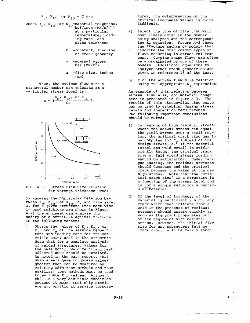
Kc’ KIC’ 0= ‘ID
= c Oda
‘here ‘c’ ‘Ic ‘ ‘r ‘ID=material toughness,ksi/inch (MN/m3/’ )at a particulartenperakure, load-ing rate, andplate thickness
C =constant, functionof crack qeo~try
a =nominal stressksi (MN/m2)
a =flaw size, inches(m)
Thus, the maximum flaw size a
structural member can tolerate at aparticular stress level is:
a . ~!sLE;::—0:–:Q ) 2
.
,,
FIG. A-3.
,., ,.0 6., 8..
,,..,,2,, . ,.,
Stress-Flaw Size Relationfor Through Thickness Crack
By knowing the particular relation be-tween Kc, KIC, or K
*?’o, axd flaw size,
a, for a given strut ure (tbe most wide–lY used relations are shown in FigureA-2) the engineer can analyze thesafety of a structure against fracturein the following manner:
1) Obtain the values of K , Kand u at the serv~ce ~~;p~a-
‘lDture and ~oading rate for the mat-erials being used in the structure.Note that for a complete analysisof welded structures, values forthe base metal, weld metal and heat-affected zone should be obtained.As noted in the main report, mostship steels have toughness valuesgreater than can be measured byexisting ASTM test methods and thusauxiliary test methods must be used
‘O.‘S?’mte ‘ID “a:ues.Altho”’qb
th=s xs a very desirable conditionbecause it means most ship steelsa=e not brittle at service tempera–
2)
3)
tures, the determination of thecritical toughness values is quitedifficult.
Select the type of flaw that willmost likely exist in the memberbeing analyzed and the correspond-ing K1 equation. Figure A-2 showsthe fracture mechanics models thatdescribe the most comurm types offlaws occurring in structural mem-bers. Complex shape flaws can ofterbe approximated by one of thesemodels. Additional equations toanalyze other crack geometries aregiven in reference 16 of the text.
Plot the stress-flaw–size relationusing the appropriate K1 expression.
An example of this re2’atiOn betweenstress, flaw size, and material tough–ness is presented in Figure A-3. Theresults of this stress-flaw size curvecan be used to establish design stresslevels and inspection requirements.The following important conclusionsshould be noted:
1)
2)
In regions of high residual stress,where the actual stress can equalthe yield stress over a small reg-ion, the critical crack size has tobe computed for u instead of thedesign stress, u.y lf the material(steel and weld metal) is suffi-ciently tough, the critical cracksize at full yield stress loadingshould be satisfactory. Under fati-gue loading, the residual stressesshould decrease and the criticalcrack becomes the value at the de-sign stress. Note that the “crit-ical crack size” in a structure isa function of the stress le”el andis not a single “alue for a partic-ular material.
If the level of toughness of the
material is sufficiently high, any
crack which ~ initiate from a
weld in the presence of residualstresses should arrest quickly assoon as the crack propagates outof the region of high residualstress. However, the initial flawsize for any subsequent fatiguecrack growth will be fairly large.
P-18 L----
.— .— .
3) For design stress levels, checkthe calculated critical cracksize. If it is larger them theplate thickness, crack growth (byfatigue) should lead to relaxationof the constraint ahead of thecrack , i.e., plane-stress behav-ior. For this case, the K(critical plane-stress str~ss-in-tensity factor) will be greaterthan K
& ‘r ‘ID which is anadditl $al degree of conser”atisrn.
4) For steels with low-toughnessvalues and high design stresslevels, e.g. , design stress of60 ksi (414 MN/m’) an~aKcof60 ksi inch (66 MN/m3 2,,Figure A-3, the steel could stillbe used ~f the design stress isreduced simifica”t~. However ,use of structural steels withlow-tDughness levels requiresprecise levels of total in.5p~c:~ig~ of the structure and is notconsidered ,Keasible for ships,,.
EFFECT OF TEMPEP.ATUR3 , LOADING RATE,AND THICKNESS ON Kc, KIC, or KID
General
In principle, the application offracture mechanics in analysis of flaw-ed members is straightforward, as shownin the pre”ious examples . In rea~,however , the application of fractwemechanics to analyze flawed metiersdepends on the engineer ha”ing specif-ic information in the following areas:
1) stress Analysis of Cracks
The stress–intensity factor,K~, has been established forvarious crack geometries, andcan be approximated for othergeometries. Thus the applica-tion of fracture mechanicsgenerally is not hampered bythe availability of stress-intensity factors for variousshape cracks. The lW3Stcommonly used stress-intensityfactors were sho”n in FigureA-2.
2) Actual Flaw Sizes
The actual fla” size in astructure is very difficult todetermine. Such factors asquality of inspection, skill ofthe inspector, a“ailable eq”ip-ment, etc. , make the determina–tion of actual flaw sizes in astr”ctwe extremelv difficult.From an ergineerin< viewpoi~t,---——the designer must assume that,the largest possible reasonablesize flaw can be present in —regions of maximum stress unlesshe has specific knowledge tothe contrary.
3) Crack-Toughness Values for Par–titular Materials
As is well known, the inher-ent crack toughness of most struc-tural steels decreases with de–creasing temperature and/or in-creasing loading rate. In addi-tion the notch toughness also de-creases with increasing platethicknesses up to the limiting“al”e of plane strain, K1 ofK Thus, before the en~ineerc$~ “predict the fracture beha”-ior of a particular structuralmetier, “sing concepts of frac–ture mechanics, he must know theKc value for the particular ser-v~ce temperature and loading rate,as well as member thickness.Very little quantitative informa-tion on the crack toughness ofship steels currently exists, al-though that which does exist in-dicates that the toughnesslevels of these steels are higherthan can be measured “sing exist-ing ASTM Standardized Test Meth-ods . Thus auxiliary test methodsare necessary to estimate thecrack-toughness levels of shipsteels.
Thickness Effects__
Ahead of a sharp crack, the later-al constraint is such that through-thickness stresses are present. Se-cause these stresses must be zero ateach surface of a plate, the through-thickness stresses are less for thinplates compared with thick plates. Forvery thick plates, a triaxial state-of-stress occurs which reduces the appar-ent ductility of the steel and the notchtoughness is reduced. This decreasein notch tDughness is controlled bythe thickness of the plate, even tho”qhthe inherent metallurgical propertiesof the material are unchanged. Thusthe notch to”,ghness (Kc! decreases forthick plates compared w~th thinnerplates of the same material. This be-havior is sho”n in Figure A-4 , for ahigh strength maraging steel. For thick-nesses greater than some value relatedto the to”qhness and strength of indiv-idual steels, maximum constraint occursand Plane strain (K ) behavior results..Con”erselY, as the $~ickness of theplate is decreased (even thoug~_t~~inherent metallurgical characteristicsFf–lTe– ~;~~i—a~~– n~~–~%~>~~d~ vtT17a–––notch-toughness Increases and pl.ane-stress (Kc) beha”ior exists.
Figure A-5 shows the shear lipson the surface of fracture test speci-mens ha”ing different plate thicknesses.The percentage of shear lips .?.scom-pared with the total fracture surfaceis a qualitative indication of notchtoughness . A small percentage of shear

lips as compared with the total frac-ture surface is a qualitative indica-tion of notch toughness. A small per-centage of shear lip area indicatesa relative brittle behavior. A compar-ison of the fracture surfaces in FigureA-5 shows that thinner plates are moreresistant to brittle fracture thanthick plates. This fact is not new toengineers, but the fact that a quanti -~t~~e fracture mechanics analysis ofthe phenomena can now be made ~ new.
m I ?lane stress!- ?hne strain
‘“:oL-Jz3!r 1)m .N !4 ., ,.0 ,., ,.0 ,.,
mlmmss,,,,2)
FIG. A-4. Effect of Thickness on K,.Behavior
~emperature and Loading Rate __
In general, the crack toughness ofmost steels decreases with decreasingtemperature and increasing loading rate.Loading rate refers to the time ittakes to reach maximum load and fornmst structures can vary from very slow(essentially static fOr KIC) tO dynan-ic (usually impact loading rates for
‘ID) “ Examples of this type behaviorfor two ship steels, AsS-C and A517,were presented in Figures 8 and 13.Note that the same general behaviorexists for the K , CVN, and DT testresults (Figure i?) but that the rapidincrease in values occurs at differenttemperatures because the tests areconducted at different loading rates.The actual loading rates fOr nmststructures are generally between thelimits of “statig” loa~ing (strain rateapproximately 10 5 sec 1) and dynamicor impact (strain rate approximately10 see-1, . If specific information onthe loading rates of actual structurescan be obtained, an intermediate load-ing rate (Figure 5) can be used toanalyze the fracture behavior. However,intermediate loading-rate tests areextremely expensive to conduct.
The salient features of the resultspresented in Figures S, 13, and A-4may be suunnarized as follows:
1.”1-.,..”.-.
,.: -.::, ; . . ,;.,,:, ,, .,>
s: %..,+.,,..,.
.,’.
<
,,,. ”.”
FIG. A-5. Effect of Specimen ThicknessToughness as Determined
Increasing test temperature ~creases the K , Kvalue at a pa?tic~?;r”;o~~~ng—.—-
rate for most structural steels.
Increasing_ the loading rate de-creases the critical K or KIC
“=lue ‘0 a ‘1Pvalue a~ a par-
t~cular tempe ature for most
(2-, 1 1/2-, 1-, and 1/2- inches) onby Size of Shear Lips
P-20
structural steels.
3) Increasing the thickness of theplate of steel being investi-gated decreases the Kc valm toa lower bound KIC value, FigureA-4.
STATIC VERSUS DYNAMIC CONDITIONS
Current methods of design andfabrication are such that engineersexpect structures to be able to tol-erate yield stress loading in tensionwithout failing. Tbe maximum allowableflaw size in a member can be relatedto the notch toughness and yieldstrength as follow:
K, Or KID,a . (~.-~c——–.
co )Y
For conditions of maximum con-straint (plane strain) , such as woddoccur in thick plates or in regionsof high constraint, the flaw size be-comes proportional to (K1c/o )2 , whereboth K
3and o should be me~sured at
the se $ice te~perature and loadingrate of the structure.
Thus the K /. ratio (or K /o ~) becomes a g~~d ~ndex for mea;~ringt~e relative toughness of Structuralmaterial. Because for most structuralapplications it is desirable that thestructure tolerate large flaws withoutfract”xinq, the “se of materials withhigh K1 /~” ratios is a desirableConditlgn. y
The question becmes , how highmust the K1c/o ratio for .5structuralmaterial be toylnsure satisfactory per-formance in complex “elded structuressuch as ships, where complete initialinspection for cracks and continuousmonitoring of crack growth throughoutthe life of a structure are not alwayspossible, practical, or economical.
No simple answer exists becausethe engineer must take into accountsuch factors as the design life of thestructures, consequences of a failurein a Structural member, redundancy ofload path, probability of overloadsand fabrication and material cost.
. However, as described in the main re-prt, fracture mechanics can pro”ide an’enqineerinaapproach to rationally eval-
to minimize the possibility of plane-Strain behai.ior). Therefore, theK / D ratio for materials used in par-t~~ul~r structure is one of the primarycontrolling parameters that defines the
. ... ...
relative safety of a struct~e agairstbrittle fracture.
If a structure is loaded “slowly-(-lO-’in/in/second) , tbe K1 /o ratiois the controlling toughnesg p~?aueterIf, however, the structure is loaded“rapidly” (-101 in/in/second or impactloading) , tbe K /0 ratio is the con-trolling parame+~r.yDDef initions a“dtest conditions for each of these ratiosis as follows:
1)
2)
3)
4)
K - critical plane-strains$$ess-intensity factor underconditions of static loading asdescribed in ASTM Test MethodE-399 - Standard Method of Testfor Plane-Strain FractureToughness of Metallic Materials.
a - Static tensile yields~~ength obtained in “slow”tension test as described inASTM Test Method E-8 - StandardMethcds of Tension Testing ofMetallic Materials.
‘$D- Critical plane-strain
s ress-intensity factor asmeasured by “dynamic” or “impact”tests. The test specimen issimilar to a Kb“t is loaded t~p~?~. ‘p~;sno standardized test procedurebut the general test method isdescribed elsewhere.
:yQe;q;~:i~s;f ,,::;~,,
tensi;n test at loading ;atescomparable to those obtained inK tests. Although extremelyd~~ficult to obtain, a good eng-ineering approximation based onexperimental results of struc-tural steels is:
+ 20 ksi*yD = 5yS
As discussed in the main report,tbe toughness of ship hull steels wasanalyzed using KID/u values, bec?mseships can be sublect~~ to dynamic load-ings. If ships are loaded at somewhatlower loading rates, the use of K /
+~d0 D parameters to establish requltgughness levels is conservative.
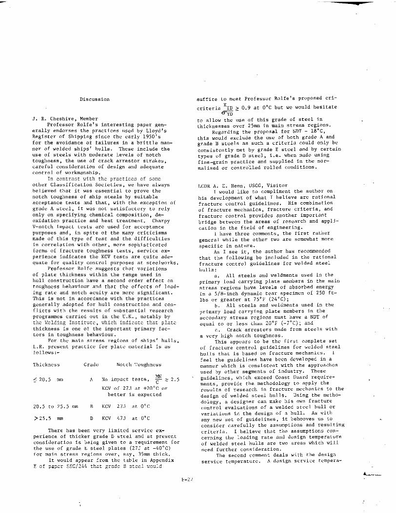
Discussion
J. R. Cheshire, MemberProfessor RolfeVs interesting’paper geD–
erally endorses the practices used by Lloyd,.Register of Shipping since the early 1950’sfor the avoidance of failures in s brittle man-ner of welded ships’ hulls. These include the.s. of steels with moderate levels of notchtoughness, the use of crack arrestor str.akes,careful consideration of design and adequatecontrol of workmanship.
In contrast with the practices of someother Classification Societies, we have alwaysbelieved that it was essential to prove thenotch toughness of ship steels by suitableacceptance tests and that, with the exception ofgrade A steel, it was not satisfactory to relyonly on specifying chemical composition, de–oxidation practice and heat treatment. CharpyV–notch impact tests are used for acceptancepurposes and, in spite of the many criticisms
made of this type of test and the difficulties
in correlation with other, more sophisticatedforms of fracture toughness tests, service ex-
perience indicate. the Kcv test. are quit. .de-q.aCe f.. q.ality control purposes at sceelworks.
Professor Rolfe suggests that variationsof plate thick”... within the range used i“bull construction have a second order effect ontoughness behaviour .a”dthat the effects of load-ing rate and notch acuity are more significant.This is “ot in accordance with the practices
gene.ally adopted f., hull COnstru.ti.n and cOn-flicts with the results of s“bst.%ttialresearch
p~ogra~e. carried uc in the u.K., notably bythe Welding Institute, which indicate that platethickness is one of the important primary fac–tors in toughness behavio”r.
For the main stress regions of ships‘ hulls,L.R. present practice for plate material is asfollows,-
‘Chick”es, Grade Notch To”Rhness
< 20.5 mm A’ No ,r.pSCt tests, ~ z 2.5
KCV of 27J at +20”C orbetter is expected
20.5 to 25.5 nun B KCV 27J at O°C
P25.5 mm D KCV 47J at O°C
There has been very limited service ex-
perience of thicker g~ade D .teel and at p.esentco”sideratio” is being given to a req”ixement fortbe use of grade E steel Plates (273 at –40°C)for main stress regions over, say, 35mm thick.
E ofIt would appear from the table i“ Appendix
paper s$c/244that g~adeB steelw..ld
suffice to meet Professor Rolfe’s proposed cri-
criteria ‘ID > 0.9 at O°C but w. would hesitate~% -
to allow the .s. of this grade of steel inthicknesses over 25mm in .nai”stress regions.
Regarding the proposal for l?DT- 18°C,this would exclude the “se of both grade A a“dgrade B steels as such a criteria could O“lY beconsistently met by grade E steel and by certaintypes of grade D steel, i.e. when made usingfine-grain practice and supplied in the “or-malised or controlled rolled conditions.
LCDR A, E. Henn, USCG, Visitor1 would like to compliment the author on
his development of what 1 believe are rationalfracture control guidelines. His comhi.ati.nof fracture mechanic., fracture c~ite~ia, andfracture control provides another importantbridge between the areas of research and appli-cation in the field of engineering.
1 have three comments, the first rathergeneral while the other two are somewhat morespecific in nature.
As 1 see it, the author has recommendedthat the following be included in the rationalfracture control guidelines for welded steelhulls:
a. All steels and weldments used in theprimary load carrying plate members in the mainstress regions have levels of absorbed energyi“ a 5/8–inch dynamic tear sPe.ire...f 250 ft-lbs or greater at 75°F (24-C);
b. All steels and weldments used i“ the
p~imary 1.ad carrying plate members in thesecondary $tress regions must have a NDT ofequal to or less than 20°F (-7”c); a“d
c. crack arresters made from steels wicba very high notch toughness.
‘Cbi$appears to be the first complete setof fracture control guidelines for welded steelhulls that is based o“ fracture mechanics. 1feel the guidelines have bee” developed in amanner which is consistent with the approachesused by other segments of industry. Theseguidelines, which exceed Coast Guard req.ire-
me.t,, provide the methOd.1.gy tO apply theresults of research in fracture mechanics to thedesign of welded steel hulls. Using the metho-dology, a designer c.” make his w“ fracturecontrol evaluatia”s of a welded steel hull orvariations in the design of a hull. As withany new set of guidelines, it ‘behoovesus toconsider carefully the assumptions and resultingcriteria. 1 believe that the ass”mpticms con-cerning the loading rate a“d design temperatureof welded steel hulls are two areas which willneed further consider.%tie”.
The second comment deals with the designservice temperattire. A design service tempera-
L----+22

t... of 32°F (OaC) my be reasonable for generalcargo and tank vessels. However, 1 agree withthe authorthatfor specialapplications,suchas ice breakers and certain vessels carryingcryogenic cargoes, special consideration shouldbe given to tbe service temperature. As anexample, the CLm8t Guard specifies the follow-ing ambient design temperatures far the co”-tig.o.s bull structure of “m? liquefied gas car-riers that have a cargo containment system re-quiring a secondary barrier:
Lower 48 States
Air (at 5 knots): O-F (.180c)sea Wace. : 32°F (O”C)
a
.iir(.C 5 knots).: -20”F(-29”C)sea water , +28°F (-2-C)
Also, tbe Coast Guard requires crack arrestersi“ the deck stringer, sheer strake, and bilgestrake. The mi”imvmnacceptable grades areGrade E steel for the deck stringer and thesheer strake a“d Grades D or E for tbe bilgestrake.
My third and final comment pertains to thetonghness test of a COClpOSiteweldment. For adesigner to use the guidelines i“ e“aluati”gthe primary load carrying plate members i“ themain stxcs.s region, he needs to know the ab-sorbed energy in a 5/8 - inch dynamic tearspecimen at a specified temperature for eachsteel and weldmemt selected. For most steelsand weldme”cs this information is probably “otreadily accessible to the designer. There isanother consideration. The dynamic tear testis a tentatively accepted ASTM standard forthe base Plate a“d weld metal. Although, tbetest is “ot being used to e“aluate the cou&hnessof the heat-affected z.”. of veldments, it app-
ears the tesZ .O.ld he .sed f.. that p.~e.se.This would require a test program to verifythe suitability of the dynamic tear specimenfar evaluating the tough”.,, of the heat.affected zone and to standardize the tesringprocedure. With regard to the testing prace-dure, the author b.. suggested that the tip ofthe notch of the dy”smic tear specimen beplaced in the cencer of the heat..affectedz.”..This sbo.ld result in some average toughnessV.I.. for the heat-affected zone. However, todetermine the area of the he~t-affected ..”.which has undergone the greatest red.ctio” intoughness due to welding, it seems that atleast two dynamic tears specimens will beneeded at two or more locations (i.e. 2mm,5mm a“d 8mn from the fusion line)
This .On.ludes mY co~ent.. Again 1 wouldlike to compliment the author .. his excellent
paper and express my thank. for a. Oep..E.nityto offer comments.
E“ge”e A, Lange, VisitorThis paper presents a much needed analyeis
for the control of fracture in ships. It isbecoming more a“d nor. embarrassing co write ..talk on fracture mechanics technology and n..as illustrations the two broken tankers, one aT-2 that broke i“ 1943 a“d o“. a barge typethat broke in 1972, a“d call the illustration,‘>Thirty years ot Engineering Progress. ,3 Theeconomics of ship co.str”czion may have j“sti-
fied the minimal corrective measures with re-spect to fracture in ships that have bee” takenduring the past 30 years, b“t as Dr. Rolfe p.ai”csout, ~he measures taken in design refinementhave not been sufficient to preclude catastrophicfractures. The big question is how much will itcost to have a more fracture resistant steel inthe critical regions.of a ship. The ec.a”omicfa~tors will change as improved steels are mademore avail~ble at a nominal premium. However,even with a premium of 10% on the price of tbesteel that is to be used i“ the 20% of a shipthat is considered critical, the o“erall costof cbe nat.,-ialsfor the ship should not increasemore tba” L% or 2%, a small increnra”tin costto precl,,,. fracture.
Dr. Rolfe’s justification for cne use ofdynamic criteria should be expanded “PO”. Cer-tainly, tbe etatic fracture to”gbness propertiesof the conventional steels used for ship.,bridges, pressure ves.els, etc., control tbe
performance of most structures i“ service.However, if a local condition develops a“d asmall crack pops in, then the dynamic proper–ties of tbe steel control tbe performance ofthe structure e“en though the “cmi”al loads arestatic or p?.eudostatic,
Dr. Rolfe points out thst tbe criteria forthe fracture resistance of steels for bridgesare based upon an “intermediate loading rate,,,a“d vbile most bridges stay “p, some do havecostly fractures that would not have been
~f;l~~ even with the current criterion,In Ref. 1, Mr. Harry Czyzewski re-
ported on a fracture that o.c”rr,d in 1971 thatled to repair costs of S5 million for a bridgein Portland, Oregon, and the redesign of threeothers. That amount of money would have paidthe premi”tno“ rhe sreel i“ the critical melu-bers of quite a few bridges. 1“ the report,Ref. 1, be painted our that the “ew require-ments for the replacement steel .,?.sa Charpy V-notch value of 1S ft-lb (20.4 J) to be met at40”F (4.4-C) which is intended to preclude frac-ture down to O°F (–18-C). However, the datacited for tbe steel in the girder that failed ac35°F (1.6”C) “,,. i“ ft-lb (J); 31 (42.3),33.2 (45.2), 15.5 (21.1), 24 (32.6), 16.5(22.4) at 40°F (4.4”C). It is apparent thatsteel that was involved i“ the fractured girderswould ba.vepassed the mew criterion, obviouslya fracture toughness criterion based upon anintermediate loading rate does not reliably pro-tect a welded steel struct”r. from catastrophicfracture. Therefore, a ~ fracture tough-ness criterion io not considered ‘,conservativeffif the performance of the steel i“ a structuremust he certified. Tbe importance of a dynamiccriterion was first doc.me”ted in tbe analysisof the massive anwu”t of service data on !4w11ships.
One of the earliest reports on the .s. ofthe Drop–weight NDT test in the analysis of NW11 ship fracc”res was by Puzak, Babecki, a“dPellini in 1958, Ref. 2. Over the years thisanalysis has been refined a“d Pelli”i publishedan updated version that introduced linearelastic fracture uech.aaicsto the analysis i“1973, Ref. 3. Mr. Pelli”i points out that shipfra.t”res initiated a“d totaled the ship whenthe fracture resistance of the steel was 1.ssthan 0.5 KIDITyd (< NDT Cenpera.t”re),but only
P-23,* -
{
I
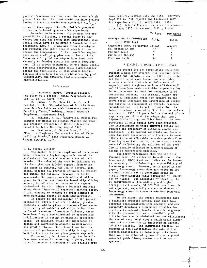
Partial fra.tu.es occurred when there was a high
probability Chat the crack T:culd run into a platehavinga fractureresistanceabove0.9 K /.ID ydIt would thus ,Pp,~,that Dr. Rolfe,s proposedcriterionis based upon serviceexperience.
In order to have steelplatesmeet the Pro-posedRolfe criterion,a recentstudyby Haw-thorneand Loss has shown thatcmvention.1 shipsteelswouldhave to be givena normalizedheattreatment,Ref. 4. There are other techniquesfor refiningthe grainsize of steelsto de-creasethe temperatureof the tr.msitianregion,suchas micraalloyingplus controlledrolling.These metallurgical techniques have bee” usedrecently to develop steels for arctic pipelineuse. If it prove. economical to use these steelsfor ship construction, this could significantlyexpand the flexibility of ship design becausethe “ew steels have higher yield strength, goodweldability, and improved fracture toughnesscharacteristics.
References
1. Czyewski, Harry, “Brittle Failure:Tbe Story of a Bridge,,,Metal Progress/west,Vol. 1, No. 1, March 1975.
2. P.zak, P. P., Babecki, A. J., andPellini, W. S., “Correlations of Brittle Frac-ture Service Failures with Laboratory Notch-Ductility Tests,,,Welding Journal ResearchS“pP1ement, September 1958,
3. Pellini, W. S., “A”alytical Design Pro–ced.res for Metal. of Elastic-Plastic and Plas–tic Fra.t”re Properties,,,Welding ResearchCouncil Bulletin No. 186, A“.g.st1973.
4. Hawthorne, J. W. and Loss, F. J.,“Fract”re Toughness Ch.aracteriz.ationof Ship.building Steels,,fShip Strncture CmnmitceeXepO,t SSC_248, 1974.
1. L. Stern, VisitorThe author is to be complimented on a paper
which pres’e”tsa losical approach toward theanalysis of fracture characteristics of hullsteels. The value of the work is indicated bythe fact that the SSC-244 report, from whichthe paper is derived, has led to several addi-tional onsoing SSC projects intended to amplifya“d pursue the subject. However, to fullyappreciate the paper, consideration should beSiven to its content from the broad shipbuildingaspect, i“ addition co the materials aspectemphasized therein. Since a detailed analysisalong these Ii”es would represent another paper,1 will co”fi”e my remarks to brief comment ofsome pertinent points of such consideration.
1“ regard to the disc”ssicm of the general
problem of brittle fracture in ships, sreateremphasis should be given to the excellent serv-ice history of welded steel ships rather thanisolated instances of service failures, whichhave been 10.s since corrected by appropriatemodifications in desisn or material specifica-tions. In addition, while the importance ofdesign and fabrication aspects is mentioned,the sreat i“fl”e”ce that these items ha”e onthe overall performance of a ship in regard tobrittle fracture is “ot Siven.proper emphasis.
For example, i“ illustrating that brittlefractures are still occurring in ships, Boydis referenced as a reporter of t.” brittle frac-
ture failures between 1960 and 1965. However,Boyd (1) in 1970 reports the followi”s serv–ice experience for the year. 1949 - 1963:
(1) Brittle Frac.ure in bteel Structures -G. M. Royal1970, Butterw.rth & C,., L:nd.n
Tankers Dry carp,.
Average No. i“ Cmmnissi.on 2,431 8,404(over 25OO t.n)
Asgregate Y..rs .f service 36,467 126,070No. broken in t“. 15 5Prc-War builtWar built (40-45) : 4Post War built 4* 1
* (l-1946; 1.19Ls; 2.19,!; !.195z)
The record for dry cargo ships would notsuggest a need for concern of a fracture prob-lem with hull steels i“ “se i“ 1963; the prob-lem should he of even lesser concern today, i“view of the fact that since 1963 steels ofsuperior “etch toushness such as ABS Grades Eand CS have been made available to provide forlocations where the need for toushness is ofparticular co”cer”. The somewhat higher fre-
q.ency of fract.r.s noted for tankers in the.abo”etable indicates the importance of designand service in assessment of o“erall fractureccmsideratio”s. lt is well to note that thelatest fracture reported hy Bovd for the tankers ;occurred in 1952, 11 years before the end of thereporting period, and that since that time,improvements thrcwgh modifications of the com-
position. of ship steels have been effected.The introduction of these improved steels he.reduced the freq”e”cy of “.isa”ce cracks ap-preciably. With current materials a“d techno-logy the rare occurrence of a fracture is morelikely to be attributable to a design detail orfrom improper fabrication, rather than a basicmaterial deficiency; the solution of the prob-lem is usually effected by a nmdificatio” ofales.is” or fabrication practice.
The paper recommends that the “se of a
Dynamic Tear (DT) .riCerion in addition to theDrop Weight (DWT) test and indicates the formeris necessary for eliminating the possibility oflow-enersy shear. However, as is noted i“ the
paper, l.w-enersy shear does not occur in low-strength steels but is sometimes found i“steels approximating yield strensths of 100,000psi or higher. The necessity of imposing theDT requireme”c an the ordl”ary and higherstrensth hull steel., 51,000 1’.s.a“d lower is“ot apparent, especially since the absence oflowe”ersy sbe.arin these steels has bee” welldocunw”ted.
In the paper, the author recos”izes thata realistic fracture control plan must Cake.Co”omic considerations into accmmt, and ..”.seque”tly develops a plan which provides forsteels with moderate levels of notch to.sh”ess.
with the Propo.ed .~ite.ia, possibility ofbrittle fracture is ui”irmizedb“t not elini”ated;the we of “cry tough steels which would elimi-
.
“ate brittle fracture is indicated as economi-cally mfeasibk. The unanswered question re-uaini”g is the quantitative estimate of thereduced possibility of catastrophic failuresthat would be effected by use of the proposedmaterial guide Ii”es, and/or crack arrest.rsystems.
P.24 p—
f.
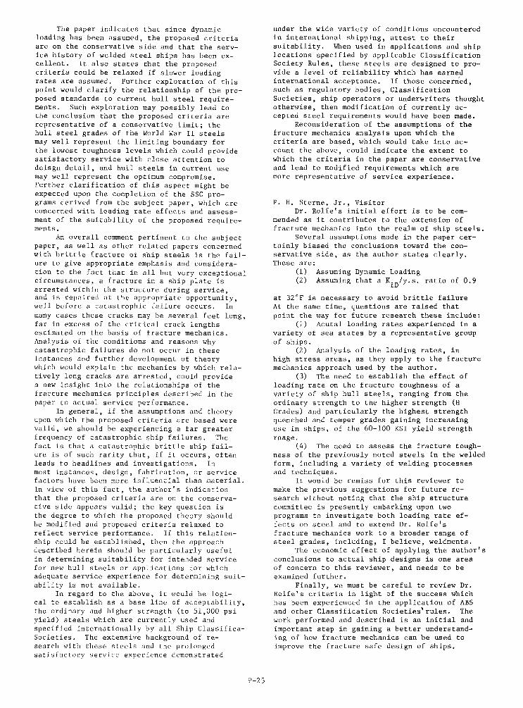
The paper indicatesthat sincedynamicloadinghas been assumed,the proposedcriteriaare on the conservativeside and that the serv-ice historyof weldedsteelshipshas been ex-cellent. It alsostatesthat the proposedcriteriacouldbe relaxedif slowerloadingratesare assumed. Furtherexplorationof thispointwould clarifythe relationshipof the pro–posedstandardsto currenthull steel require–ments. Such explorationmay possiblylead tothe conclusionthat the proposedcriteriaarerepresentativeof a conservativelimit;thehullsteelgradesoftheWorldWarIIsteelsmaywellrepresentthelimitingboundaryforthelowesttoughnesslevelswhichcouldprovidesatisfactoryservicewithcloseattentiontodeisgndetail,andhullsteelsincurrentusemaywellrepresenttheoptimumcompromise.FurtherclarificationofthisaspectmightbeexpecteduponthecompletionoftheSSCpro-gramsderivedfromthesubjectpaper,whichareconcernedwithloadingrateeffectsandassess-mentofthesuitabilityoftheproposedrequire-ments.
Anoverallcommentpertinenttothesubjectpaper,aswellasotherrelatedpapersconcernedwithbrittlefractureofshipsteelsis thefail-uretogiveappropriateemphasisandconsidera–tiontothefactthatinallbutveryexceptionalcircumstances,a fractureina shipplateisarrestedwithinthestructureduringservice,andisrepairedattheappropriateopportunity,wellbeforea catastrophicfailureoccurs.Inmanycasesthesecracksmaybeseveralfeetlong,farinexcessofthecriticalcracklengthsestimatedonthebasisoffracturemechanics.Analysisoftheconditionsandreasonswhycatastrophicfailuresdonotoccurintheseinstancesandfurtherdevelopmentoftheorywhichwouldexplainthemechanicsbywhichrela-tivelylongcracksarearrested,couldprovidea newinsightintotherelationshipsofthefracturemechanicsprinciplesdescribedinthepapertoactualserviceperformance.
Ingeneral,iftheassumptionsandtheoryuponwhichtheproposedcriteriaarebasedwerevalid,we shouldbeexperiencinga fargreaterfrequencyofcatastrophicshipfailures.Thefactisthata catastrophicbrittleshipfail-ureisofsuchraritythat,ifitoccurs,oftenleadstoheadlinesandinvestigations.Inmostinstances,design,fabrication,orservicefactorshavebeenmoreinfluer.tialthannaterial.Inviewofthisfact,theauthor’sindicationthattheproposedcriteriaareontheconserva-tivesideappearsvalid;thekeyquestionisthedegreetowhichtheproposedtheoryshouldbemodifiedandproposedcriteriarelaxedtoreflectserviceperformance.Ifthisrelation-shipcouldbeestablished,thentheapproachdescribedhereinshouldbeparticularlyusefulindeterminingsuitabilityforintendedservicefornewhullsteelsorapplicationsforwhichadequateserviceexperiencefordeterminingsuit-abilityisnotavailable,
Inregardtotheabove,itwouldbelogi–caltoestablishasa baselineofacceptability,theordinaryandhigherstrength(to51,000psiyield)steelswhicharecurrentlyusedandspecifiedinternationallybyallShipClassifica-Societies.Theextensivebackgroundofre-searchwiththesesteelsandtheprolongedsatisfactoryserviceexperiencedemonstrated
underthewidevarietyofconditionsencounteredininternationalshipping,attesttotheirsuitability.WhenusedinapplicationsandshiplocationsspecifiedbyapplicableClassificationSocietyRules,thesesteelsaredesignedtopro-videa levelofreliabilitywhichhasearnedinternationalacceptance.Ifthoseconcerned,suchasregulatorybodies,ClassificationSocieties,shipoperatorsorunderwritersthoughtotherwise,thenmodificationofcurrentlyac–ceptedsteelrequirementswouldhavebeenmade.
Reconsiderationoftheassumptionsofthefracturemechanicsanalysisuponwhichthecriteriaare based,whichwouldtakeintoac-counttheabove,couldindicatetheextenttowhichthecriteriainthepaperareconservativeandleadtomodifiedrequirementswhicharemorerepresentativeofserviceexperience.
F.H. Sterne,Jr..VisitorDr.Rolfe’sinitialeffortistobecom–
mendedasitcontributestotheextensionoffracturemechanicsintotherealmofshipsteels.
Severalassumptionsmadeinthepapercer–tainlybiasedtheconclusionstowardthecon-servativeside,astheauthorstatesclearly.Theseare:
(1) AssumingDynamicLoading(2) Assumingthata KID/y.s.ratioof0.9
at32°FisnecessarytoavoidbrittlefailureAt thesametime,questionsareraisedthatpointthewayforfutureresearchtheseinclude:
(1) Acutalloadingratesexperiencedinavarietyofseastatesbya representativegroupofships.
(2) Analysisoftheloadingrates,inhighstressareas,astheyapplytothefracturemechanicsapproachusedbytheauthor.
(3) Theneedtoestablishtheeffectofloadingrateonthefracturetoughnessofavarietyofshiphullsteels,rangingfromtheordinarystrengthtothehigherstrength(HGrades)andparticularlythehigheststrengthquenchedandtempergradesgainingincreasinguseinships,ofthe60-100KSIyieldstrengthrnage.
(4) Theneedtoassessthefracturetough-nessofthepreviouslynotedsteelsintheweldedform,includinga varietyofweldingprocessesandtechniques.
Itwouldberemissforthisreviewertomaketheprevioussuggestionsforfuturere–searchwithoutnotingthattheshipstructurecommitteeispresentlyembarkingupontwoprogramstoinvestigatebothloadingrateef-fectsonsteelandtoextendDr.Rolfe’sfracturemechanicsworktoa broaderrangeofsteelgrades,including,I believe,weldments,
Theeconomiceffectofapplyingtheauthor’sconclusionstoactualshipdesignsisoneareaofconcerntothisreviewer,andneedstobeexaminedfurther.
Finally,wemustbecarefultoreviewDr.Rolfe’scriteriainlightofthesuccesswhichhasbeenexperiencedintheapplicationofABSandotherClassificationSocieties’rules.Theworkperformedanddescribedisaninitialandimportantstepingaininga betterunderstand-ingofhowfracturemechanicscanbe usedtoimprovethefracturesafedesignofships.
P-25
P. R. Christopher, VisitorProfessor Rolfe states “.>P. 11 that thick-
ness has a second.order effect cm toughnessbehavior in the transition temperature regioncompared with the first-order effects of load–ing rate and notch acuity. From the D. W. ‘r.
graphs sh.wn i. Figure 11, Figure 12 and Figure13,it might be supposed that the thickness ef-fect is small although the temperature scaleused, perhaps, disguises the fact that there issome definit. increase in tans ition tempera-Cure which might be crucial 1. a give. steel fora particular application. Certainly guidancenotes for offshore steel properties in the U. K.
make a distinction between plates above a“d be-
low 1“ thlck”ess. Indeed it is recmmne”ded thatabove 1-1/2s9thickness stress relieving shouldbe applied to important structure.
Certainly the statement that for Plate. lessthan 2“ thickness, the effects of specimen thick–ness can be ignored seem. wrong. This raisesthe important q.estio”, in relation to any test,of tbe scatter that might be expected in resultsobtained from plate to plate, and within a plateand whether or not this is greater within thetransition range. The results give” for theDWT tests i“ Figure 11 - 13, for instance, maynot be a true average particularly since, i“the transition range, there may be more thano“. arrest a“d restart of fracture. It alsoraises the q.estio. as to what strain rate isrepre,semtativeof a particular application a“d
whether or “ot impact tests are really neces–earj’since servo-hydraulic machines mey Well becapable of simulating the strain rates appliedin many service applications.
1 make these remarks because it is impar-ta.ntto be quite clear on this question of thick-ness in the O - 4“ range since it is just thisran~e which inzerests .s most in offshore ap-plications. Surely it was when thickness be–g.n t. exceed about 1’<that brittle fracturestanted to be a worry?
With respect to ship fractures 1 think the1972 failure which Professor R.lfe describedis very important. Even though it may be anisolated case 1 think that there may be much tobe learned from it.
1 was very interested i“ Professor Rolfe,sidea of .si”g a“ ,,1,,bean as a crack .I....re..the cop face being butt welded into the plating.One wonders if he has carried out any investiga-Cio”s of this idea: it is not clearwhy thecrack should “ot pass through the top faceleaving the structure held together by . ratherflimsy stri”cer.
Author,. C1OSUX,
First, 1 would like to thank the variousdisc.ssors for their comments. structuralresearch is of little value to the profession.“1.ss ic leads to improvements in the overall“nderstandi”g of the behavior and design .fship hull structure. a“d cercai”ly a“ inter-mediate step in this process is the interchs”geof ideas and discusaio”s such as the foregoingones
Mr. Cheshire of Zloyti,s F.egiscerC: Slippingis correct in poi”tit>gouc tbc.uscfulne.s of the
Charpy V-notch impact test in quality control.The Charpy test has served engineers quite wella“d will be with .s for some time.
The dynamic fracture criteriadescribedin the paper is such thatexistingABS-st’aelsprobablywill justmeet themmost of the time.Howe”’?,, to “eet them consistently 0“ a guaX-a“teed mi”im”m basis of performance, it wouldprobably be necessary to modify processing prac-tices (e.g., use normalized steel plates). Withthe general trend to probabilistic analysisand design, specification of materials on aprobabilistic basis of material propertiesrather than guaranteed minimums may be veryfeasible and might result in a more realistic“se of the dynamic criterion.
Plate thickness is important in definingconstraint. lkwrever,compered with the shifti“ tra”sitio” behavior due to loading rate (.Pto 160”F), the shift i“ tr.mwitio” temperaturebetween l-in. a“d 2-i”. thick specimens issecondary, i.e., an tbe order of 30-40”F.
A. LCDR Herm, USGG correctly notes, the
proposed f~a.tu~e c~iCeria do exceed existingCoast Guard requirements. Furthermore he i.correct i“ stating that fracture mechanics pro-vides a methodology to make fracture criterionmore or less severe th.a”that described in the
paper, based .. service conditions other thanthose described in the paper. 1 agree that theloading rate .assurnptio”is crucial and that addi-tional i“formatio” is needed.
Regarding the need for crack arrestors, aninteresting design is the use of WF shapesrather than plates. Structural shapes ofsteels with good notch toughness could haveexcellent properties because of the directionalworking during rolling. Also the mechanicalco”str.int of the WF section should provideconsiderable arrest capability. 1 agree withCommander He”n’s statement that additionalwork on toughness tes,ts of weldments is neededand certainly the experience with the Charpyv-notch impact test should not be discardedli~htly.
Mr. Lange of the Naval Research Laboratory(NRL) q“estio”s our engineering progress d“r-i,,g the past 30 pears. 1 believe that theshipb”ildi”g industry has indeed made consider-able progress since the early ship failures thatacc”rred in world War 11. Our “ndersca”di”gis better, the safety ?.”dreliability is muchbetter, and the frequency of failures i. con-siderably less. Much of the success i“ this
p~og~ess iS indeed due t. the l.ng-.tandingcontributions that the Naval Research Labora-tory, led by Bill Pelli”i, has made in the fieldof notch toughness testing of structural steel..Considerable improvements have been made i>design, fabrication, and materials since theWorld War 11 ships and the recent brittlefracture of the barge that occurred i. 1972apparently was primarily a problem in operations,rather than these other factors.
‘rbeconcept of a small crack pop-in leadingto a dynamic stress field i“ staticallyloaded structures has long been a point of con-siderable debate anm”g engineers. Perhaps itis easier to think of larger stiffeners, gussetplates, or other secondary members failing.“der overload, leading to a large dynamicstress field rather than the s“dde” pop-i” of asmall micr..ra.k lcm+dingtc a dy,,,uni.stress
I
P-26

field. Pos8ib1e failure of . secondary memberleading to a dynamic stress field emphasizesthe point that design of secondary members or
stiffeners is g “just 3 detail,,,but ,atheris a very important part of the overall designof the structure and can be as important asthe design of tbe primary load-carryingmembers.Because of the importance of details i“ a
fracture–resistantdesign, there appears to bea definite need for a “cetalog.ing” of therelative severity of typical ship details, i“the same manner that the bridge industry hasdo”, for bridge details.
Reference was made to the use of a“ inter-mediate loading rate in the development of theAASHTO material toughness specifications forbridge steels and that these specifications,adapted in 1973, would not have prevented thefracture that occurred i“ the Fremont Bridgei“ Oregon. A complete analysis of that frac-ture is beyond the scope of this discussion.However, it should he “ated that if the steelhad bee” tested in the same orientation as it
was loaded i. the structure, namely the tran..verse direction, the test results would nothave met the AASHTO requfre,ne”ts. The t..”,.verse CVN impactpropertyvalueswere: 8.8,12.5,10.0,6.5, md 6.5 ft. lbs, and thus didnot meet tk,e15 ft. lh. requirement. AC the Sametemperature. the Ion,qit.di”alvalues, whichwere “at in the primary loading direction, were31, 33.2, 15.5, 24, and 16.5 ft. lb.. AS isoften the case, other factors besides materialtoughness were involved in this fracture.
SPecifically, the particularly severe stressconcentration, and the .s. of very thickplates that were rolled lo”git.dir,ally,cuttransversely, a“d then loaded tra”$verselydefinitely contributed to this fracture.
The K fc-ID ~d 2 0.9 ratio proposed . . .
Wn.mf. ..iteri.n for welded ship hull steel.agrees with the NRL yield criterion (Y.C.)a“d is a conservative dy”mnic criterion to
provide a specific level of dynamic toughness.Designers, fabricators, and operators ~have a responsibility for the safety a“d re-
liability of structures. A realistic con...”is that if material requirements become tooconservative, designers will not pay properattention to these other factors, which are.1s. very important i“ a total Fracture ControlPlan.
Mr. 1. L. St..” of the America” Burean ofShipping is correct in bis statement thatexisting experience for ship hulls is excellentand this fact should be emphasized. Material,,design, fabrication, inspection, a“d operationare .11 important i“ the overall safety and .reliability of ship hull structure.. Thereason that more emphasis is usually given tothe role of notch toughness of materials asa factor affecting brittle fracture rather thanthe role of design, fabrication, inspection,and opera.cio” is that few designers appearto be really interested in the importance ofstructural details. Thus some toughness 1,”,1is desired to compensate for possible fabrica-tion or design errors. This i.a“ot .lwaY.the most eco”.mnicalor e“en the most desirablesolution but is .“. that is widely used. Alarge need is to “catalog” the severity oftYP*cal details -– similar to the way AISC h,,
cataloged bridge details so that the severiryof certain details is established.
In respo”.seto another quescio” by Hr. 1.L.Stern, 1 would agree that low-energy shear isreally “ot a problem with low-strength steelsand that while desirable for completeness of thecriterion, the DT requirement may “ot benecessary for low-strength steels.
As indicated i“ the paper, the theoreci..alcrack size, a for low-stress levels can beC.,se”er.alfeet long, in fact, i“ some cases semi-infinite. A fracttiremechanics analysis issomewhat ntea”inglessin this case, in thesame manner that a“ Euler buckling analysis thatresults i“ a critical buckling stress muchlarger (for very small~/~) than the yieldstrength is mea”ir,gle.s. In both cases, othermodes of failure control the beh.a”iorbut theconcepts of both these analyses are used toinsure that failures do “ot occur by these
Parric.lar modes of failure.1 would also agree that if .11 structures
were loaded dynamically, we might be exper-iencing a far greater frequency of catastrophicship failures than we are. The same staceme”t
...ld be made for bridges, leading to the co”-
.Iusion that the loading rate shift may wellexplain why me”y ships a“d bridges perform verysatisfactorily at temperatures below their
dynamic NDT temperature.Mr. R. H. Stern. of Luke”. Steel raises a
W-tin %wrdiw the ..sumption of a dynamicloading rate. Certainly, es a starting point,dynamic loading sh.uld be assumed until abetter .ndersta”di”g of the implications ofthis ass”mptio” are understood, and this waswhat was done in the Ship Structure Committee(SSC) research. However, in view o’fthe excel–lent ser”ice experience of ship .sceels,theneed far this .ase.mptio”certainly b.asa rightto be questioned, although all str”ct”ralsteels should have some ninim”m (moderate)level of “etch toughness. Additional work isnecessary to determine what the optimum trade-off between safe, reliable material behaviorand economics actually is.
As Mr. Sterne has noted, the Ship Str.ct”reCommittee is conducting research cm:
.. loading rates for ship steels a“db. a study of the adequacy of the dynamic
criterion.One additional program which should be
recommended to tbe SSC is a study and c.at.alogu-i“g of the severity of typical design details,both from a fracture as well as a fatigueviewpoint. If the designer had some i“dlcationduring the design stage of just how deleteriouscertain details are, they could be elini”ated.AISC has done this far various bridge details .and the allowable fatigue stress range isdecreased as the se”erity of the detail isincreased
M.. Christopher of the Naval ConstructionResearch Establishment of the United Kingdom
Points out that thickness is important and 1agree with his statement. However, it is “.t
,
as sig”ifica”t as the loading rate shift forthickness up to 2–i”cbes. For thicknessesgreater than 2-inches, 1 agree that mmmtr.ai”tbecomee increasingly more important. scatteri“ material properties certainly is a fact oflife that must be dealt with. The general movetoward probabilistic design may provide a
P-27,L

— -——
better solution to this situation than the
p.e.ent use of guaranteed minimum values.on.. again, 1 would like to thankthe
reviewersfor theirinterestas shownby theirpertinentdiscussions.Thank y...
P-28 f=—

Discussion
J R. Cheshire, MemberProfessor Rolfers interesting paper gen-
erally endorses the Prattices used by Lloyd,sRegister of Shipping since the early 1950’sfor the avoidance of failures in a brittle man-ner of welded ships’ hulls. These include theuse of steels with moderate levels of notchtoughness, the use of crack arrestor s.tr.skes,careful consideration of design and adequatecontrol of workmanship.
ln contrast with the practice. of someother Classification Societies, we have alwaysbelieved that it was essential to prove thenotch toughness of ship steels by suit.shleacceptance test. and that, with the exception ofgrade A steel, it was not satisfactory to relyonly on specifying chemical compositi.”, de-oxidation practice and heat treatment. CharpyV–notch impact tests are used for acceptance
purpo.es and, in spice of the ~ny crft<ci.~made of this type of test and the difficultiesin correlation with other, more sophisticatedforms of fracture to.gh”ess tests, service ex-
perience indicate. the KCv tests are quite ade-quate for quality control purposes at steelworks.
Professor Rolfe suggests that variationsof plate thickness within the range used inhull construction have a second order effect o“to.gh”ess behaviour a“d that the effects of load-ing rate .a”d“etch acuity are more significant.This is not i“ accordance with the practices
8enera11y adopted for hull .onst~u.ti.. and CCXI-flicts with the results of substantial researchpwra~es carried OUt in the U.K., norably hythe Welding Institute, “hich indicate that platethickness is one of the important primary fac-tors in Lough”es. behavicnu.
For the rnai”stress regions of ships’ hulls,L.R. present practice for plate material is asfollows:-
Thick”ess Grade Notch Tough”,,,
<20.5 m A NO impacttests, $ z 2.5
KCV of 27J at +20”C orbetter is expected
20.5 to 25.5 mm B KCV 27J at O°C
>25.5 mm D KCV 47J at O“C
There has bee” very limited service ex-perience of thicker grade D steel a“d at prese”cconsideration is being given to a requirement forthe use of grade E steel plates (27J at -40”C)for main stress regions over, say, 35mm thick.
IC would appear from the table in Appendix
E of paper SSC/244 that grade B steel would
suffice to meet Professor Kolfe’s proposed cri-
criteria ‘ID > 0.9 at O°C but we would hesitatec= -
to allow the use of this grade of steel inchfckne.ssesover 25m in main stress regions.
Regarding the proposal for NDT - 18-C,this would exclude the use of both grade A andgrade B steels as such a criteria could .nlY beconsistently met by grade E steel.md by certaintypes of grade D steel,i.e.when made usingfine-grain practice and supplied i“ the nor-malised or controlled rolled conditions.
LCDK A. E. Eenn, USCG, visitor1 would like to compliment the author on
his development of what 1 believe are rationalfractme control guidelines. His combi”ationof fracture mechanics, fracture criteria, andfrac’mre control provides another importantbridge between the areas of research and appli-cation in the field of engineering,
1 have three comments, the first rathergeneral while the other two are somewhat morespecific in nature.
As 1 see it, the .Whor has recommendedthat the following be included in Zhe rationalfracture control guidelines for welded steelhulls:
a. All steels and veldments used in theprimary load carrying plate members in the mainstress re,io”s h~”e 1,”,1s of absorbed energyi“ a 5/8-~nch dynamic tear specimen of 250 ft-lbs or greater at 75°F (24°C);
b. All steels a“d we1dment8 used in the
wimw l..d CWYin8 plate members in thesecondary stress regions must have a NDT ofequal to or less than 20” F (-7”C); and
. . Crack arresters made from steels witha very high notch toughness.
This appears to be the first complete setof fracture control guidelines for welded steelhulls that is based an fracture mechanics. 1feel the g“ideli”es have been developed in amanner which is consistent with the approachesused by other eegments of industry. Theseguidelines, which exceed Coast Guard require-
ment,, provide the methodolOgY to applY theresults of research in fracture mechanics to thedesign of welded steel hulls. Using the metho-dology, a designer can make his .“” fra.t”recontrol eval”atio”s of a welded steel hull orvariations in the design of a hull. As withany new set of g“idelimas, it behoove. us to .
consider carefully the assumptions and resultingcriteria. 1 believe that the assumptions cm”-cerning the loading rate and design temperatureof welded steel hulls are two areas which willneed further consideration.
The second comment deals with the designser”ice remperat”re. A design service tempera-
P-22

t...of 32-F [O-c)may be ~easo.ablef., gene~.1cargoand tcmk vesseLs. However, 1 agree withthe author that for special applications, suchas ice breakers and certain vessel. carryingcryogenic cargoes, special consideration shouldbe given to the service temperature. As anexample, the Coast Guard specifies the follow-ing ambient design teniperaturesf.. the con-tiguous hull structure of new liquefied gas car-riers that have a cargo containment system re-
quiring . s.condw barrier:
Lower 48 StatesAir (at 5 knots):Sea Water
AlaskaAir (at 5 knots);sea water
O-F (-18-C)32-F (O-C)
-20”F(-29°C)+28°F (-2-C)
Also, tbe Coast Guard requires crack arrestersin the deck stringer, sheer strake, and bilgestrake. ‘Theminimum acceptable grades areGrade E steel for the deck stringer and the
sheer strake a“d Grades D or E for the bilgestrake.
My third and final comment pertains to thetoughness test of a composite veldnent. For adesigner to .s. the guidelines i“ e“alu.tingthe primary load carrying plate member. in themain stress region, he needs to know the ab-sorbed energy i“ a 518 - inch dynamic tearspecimen at a specified cemperat”re for eachsteel and weldment selected. For meet steelsand weldments this information is probably notreadily accessible to the designer. There isanother consideration. The dynamic tear restis a tentatively accepted ASTM standard forthe base Place a“d weld metal. Although, thetest i. not being used to evaluate the toughnessof the heat-affected zone of weldments, it ap-
p’=~s the te.t .Ould be used for that p.rp..e.This.would require a test program to verifythe suitability of the dynamic tear specimenfor evaluating tbe toughness of the heat.affected ..”. and to standardize the testingprocedure. With regard co the testing proce–d“,,, the aurhor he.,s“g~ested that che tip ofthe notch of the dynamic tear specimen beplaced in the center of che heat-affected zone.This should result i“ some a“erage to”ghr.ese“.1.. for the heat-affecced z.”.. However, todetermine the area of the beat-affected zonewhich has ““dergone the greatest reduction intoughness d“e to welding, it seems that atleast two dynamic tears speciure”tswill beneeded at two or more locations (i.e. 2mm,5mm a“d 8imnfrom the fusion line)
This cOncludes mY co~ents. Again 1 wOuldlike to compliment the author on his excellent
paper and exp~ess my Zhank. f.. an oppore..icyto offer COwments
Eugene A. Lange, VisitorThis paper presents a much “ceded .a”alysis
for the control of fracture i“ ships. It isbecoming more a“d more embarrassing c. write .rtalk o“ fracture mechanics technology a“d “seas ill”.stratio”sthe two broken tankers, one aT-2 that broke in 1943 and one a barge typethat broke i“ 1972, and call the illustration,“’Thirtyyears oi Engineering Progress.“ Theeconomics of ship co”str”ctio” may have justi-
fied the minimal corrective measures with re-spect to fracture in ship. that hav. been takenduring the past 30 years, b“t as Dr. Rolfe pointsout, the measure. taken in design refinementhave not bee” sufficient to preclude catastrophicfracr”fes. The big question is how much will itcost to have a more fracture resistant steel intbe critical regions of a ship. The economicfactors will change‘as improved steels are madema. available at a nominal premium. However,even with a premium of 10% on the price of tbesteel that is to be used i“ the 20% of a shipthat is considered critical, the overall costof the matccials for the ship should not increasemore than L% or 2%, a sm.alli“creme”c in costto precl,,‘e fracture.
DE. Kolfe’s justification for the .s. ofdynamic criteria should he expanded upon. Cer-tainly, the static fra.ctnretoughness propertiesof the conventional steels used for ships,bridges, pressure vessels, etc., control che
pe~forman.e .f most structures in service.However, if a local condition develops and aSO&Illcrack pops i“, the” the dy”mr.icproper-ties of the steel control the performance ofthe structure even though the “cminal loads arestatic or pseudostatic.
Dr. Kolfe points out that the criteria forthe fracture resistance of steels for bridgesare based upon an “intermediate loading rate”,a“d while most bridges stay up, some do havecostly fractures that “ould not have been
precluded even with the current criterion,Ref. 1. In Ref. 1, Mr. Harry Czyzewski re-
p.med .n a fracture that occurred in 1971 thatled to repair costs of $5 Inillio”for a bridgein Portland, Oregon, a“d the redeeig” of cbreeathexs. That amount of money would have paidthe premium on the steel i“ the critical mem-bers of quite a few bridges In the report,Ref. 1, he pointed out that the “ev req”ire-nmnts for the replacement steel was a Ch.arpyV-notch value of 15 ft-lb (20.4 J) to be met at40°F (4.4-C) which is intended to preclude frac–t.,, down to O°F (–18°C) However, the datacited for the steel in the girder Chat failed at
35°F (1.6-C) were in ft-lb (J); 31 (42.3),33.2 (45.2), 15.5 (21,1), 24 (32.6), 16.5(22.4) at 40”F (4.4”C) . It is apparent thatsteel that was involved in the fractured girderswould have passed the new criterion, obviouslya fracture to”gh”ess criterion based upon a“i“terrnediateloading rate does not reliably pro–tect a welded steel str”ct”re from catastrophicfracture. Therefore, a ~ fracture co.gb–ness criterion is not considered “conservativesyif the performance of the steel in a structuremust be certified. The importance of a dy”au.iccriterfo” was first documented i“ the .“aly?.isof tbe massive amount of service data o“ WW 11ships.
One of the earliest reports on the use oftbe Drop–Weight NDT test i“ the analysis of WW11 ship fractures was by Puzak, Babecki, a“dPellini i“ 1958, Ref. 2. Over tbe years thisanalysis has bee” refined .a”dPelli”i puhlisbed ,
an updated verslo” that introduced linearelzmtic fracture mechanics to the analysis i“1973, Ref. 3. Mr. Pelli”i points out chat shipfractures initiated a“d totaled the ship whenthe fracture resistance of the steel w., lessthan 0.5 KID/~yd (< NISItemperature), but only
P-23 *G —

b— - .———
Pa~tial fra.t..e, Occurred when there was a highprobability that the crack wculd r“n into a platehaving e fracture resistance above 0.9 K lo
ID ydIt would thue appearthatDr. Rolfevsproposedcriterionis based up.” serviceexperience.
In order to have steelplatesmeet the Pro–posedRolfe criterion,a recentstudyby Baw-thornea“d Loss has shownthat conventionalshipsteelswould have to be give” a normalized heattreatment, Ref. 4. Thereare other techniquesfor refiningthe grainsize of steelsto de-creasethe temperatureof the tramitian region,such as microalloyingplus controlledrolling.These metallurgical tech”iq.es have been usedrecently to develop steels for arctic pipeline.... If it proves economical to “se these steelsfor ship construct%.”, this could significantlyexpand the flexibility of ship design becausethe new steels have higher yield strength, goodweld.ability,and improved fracture toughnesscharacteristics.
References
1. Czyewski, Harry, “BrittleFailure:The Story of a Bridge,,,Metal Progress/WesC,Vol. 1, No. 1, March 1975.
2. Puzak, P. P., Bahecki, A. J., andPellini, W. S., “Correlations of Brittle Frac-ture Service Failures with Laboratory Notch-Ductility Tests,“ Melding Journal ResearchSupplement, September 1958.
3. Pelli”i, w. s., “Analytical Design Pro-cedures for Metals of Elastic-Plastic and P1as-tic Fracture Properties,,,Welding ResearchCouncil Bdletin No. 186,August1973.
4. Hawthorne,J. W. and Loss,F. J.,“FractureToughness Characterizationof Ship-building steel.,,,Ship Strncture Committee;<ep..t SSC.248, 1974,
1. L. Stern, VisitorThe author is to be ,mnplime”ted on a paper
which presents a logical approach toward theanalysis of fracture characteristics of hullsteels. The value of the work is i“dic.atedbythe fact that the SSC–244 report, from whichthe paper is derived, has led to several addi-tional ongoing SSC projects intended to amplifyand pursue the subject. However, to fully
aPP.e.iate the Paper, consideration should begiven t. it. content from the broad shipbuildingaspect, in addition to the materials aspectemphasized therein. Since a detailed analysisalong these lines would represent another paper,1 will confine my remarks to brief comment ofsome perti”e”t points of such consideration.
I“ regard to the discussion of the generalproblem of brittle fracture in ships, greateremphasis should be given to the excellent serv-ice history of welded steel ships rather thanisolated instances of service failures, whichhave been long since corrected by appropriatemodifications in design or material specific.-tio”s. 1“ addition, while the importance ofdesign and fabrication aspects is mentioned,rhe great influence that these items have o“the overall perform.”.. of a ship in regard tobrittle fracture is “ot give” proper emphasis.
For example, in illustrating that brittlefractures are still occ”rri”g in ships, Boydis referenced as a reporter of te” brittle frac-
ture failures I,eLween1960 and 1965. However,Boyd (1) in 1970 reports the following serv-ice experience for the years 1949 - 1963:
(1) Britcl.eFzac..re in bteel Str”ct”res -G, M. Boyd 1970, Butterworth & C,., L,ndon
‘rankers Dry cars.
AverageNo. in Comnission 2,431 8,4o4(over2500 ton)
Aggregate Years of service36,467 126,070No. broken in two 15 5Pre-N.?rbuilt 7w.. built (40-45) 4 4Pose War built 4* 1
* (1-1946; 1.194S; 2.19,,9;!.1952)
The record for dry cargo ships would notsuggest a need for concern of a fracture prob-lem with hull steels in use in 1963; the pr.b-
lem should be of even lesser concern today, i“view of the fact that since 1963 steels ofsuperior “etch toughness such as ABS Grades Eand CS have been made available to provide forlocations where the need for to.gb”e.ssis ofparticular co”cer”. The somewhat higher fre-
q.encY of fract.re. noted for tankers in theabo”e table indicates the importmce of designand service i“ assessment of overall fractureconsiderations. It is well to note that thelatest fracture reported by Boyd for the tankersoccurred in 1952, 11 years before the e“d of thereporting period, a“d that since that time,improvements through modifications of the com–
Po,itio.s of ship steels have bee. effected.The introduction of these improved steels hasreduced tbe frequency of “uisa”ce cracks ap-preciably. With c“rre”t materials a“d tech”o-10E!Ythe rare occurrence of a fracture is morelikely to be attributable to a design detail orfrom improper febricatio”, rather than a basicmaterial deficiency; the solution of the prob-lem is usually effected by a u.odificaticmofdesign or fahricatio” practice.
The paPer recommends that the use of a
Dynamic Tear (DT) criterion in addition to tbeDrop Weight (DWT) test a“d indicates the formeris necessary for eliminating the possibility oflow-energy shear. However, as is noted i“ the
P.Per, 10w-enerKY shear doe. not occur in low.strength steels b“t is sometimes found insteels approximating yield strengths of 100,000psi or higher. The mcessity of imposing theDT requirement o“ the ordinary a“d higherstrength hull steels, 51,000 Y.S. and lower is“ot apparent, especially since the absence oflow-energy shear in these steels has been “.11doanne”ted
In the paper, the author recognizes thata realistic fracture control pl.a”must takeeconomic considerations into account, and colI-seq”ently de”elop. a plan which provides forsteel. with moderate levels of notch toughness.With the proposed criteria, possibility ofbrittle fracture is minimized b“t “ot ellmi”ated;the “se of very tough steels which “ould elimi- ,
mate brittle fracture is indicated as economic-ally unfeasible. The una”.wered q“esticm re-nmi”ing is the q“antit.ativeestimate of thereduced possibility of catastrophic failuresthat would be effected by n,, of the proposedmaterial guide lines, .a”dlorcrack arrestorsystems.
P.24 +—
The paper indicates that since dynamicloadinghas been .ss.med,the proposedcriteriaare on the conservativeside aml that the serv-ice historyof weldedsteelshipshas bee. ex-cellent. It .1s. statesthat the proposedcriteriacouldbe relaxedif slowerloadingratesare asvmned. Furtherexplorationof thispointwould clarifythe relationshipof the pro-posed.tandardsto currenthull steel require-ments. Such exploratfon may possibly lead tothe concl.eio” that the proposed criteria arerepresentative of a conservative limit; thehull steel grades of the World w., 11 steelsnay well represent the limiting ho.ndary forthe lowest toughness levels which could providesatisfactory service with close attention todeisg” detail, and hull steels i“ current “se~Y w.11 represent the optimum compromise.Further clarificatlo” of this aspect might beexpected “pm the completion of the SSC pro-
grams derived f.om the subject paper, which areconcerned with loading rate effects and asses.-caentof the suitability of the proposed require-ments.
.4noverall cmnme”t pertinent to the subject
PaP=,, as Well as other relatedpapersconcernedwith brittlefractureof ship steelsis the fail–... to give appropriateemphasisand considera-tion :. the fact that in .11 but very exceptionalcircumstances,.a fracture in a ship plate isarrested within the structure during service,and is repaired at the appropriate opportunity,well before a catastrophic failure occurs. 1.many cases these cracks may be several feer long,far in excess of the critical crack lengthsestimated on the basis of fracture mechanics.Analysis of the .onditions and reasons whycatastrophic failures do “ot ..... i“ th.s.imtames and further development of theorywhich would explain the mechanics by which rela-tively long cracks are arrested, could providea new insigkt into the rela.tio”ships of thefracture mechanics principles described i“ the
paper t. a,t..1 service performance.In ~eneral, if the assumptions and theory
“pen which the proposed criteria are based werevalid, we should be experiencing a far greaterfrequency of catastrophic ship failures. Thefact is that a catastrophic brittle ship fail-“.. is of such rarity that, if it occurs, oftenleads to headlines and investigations. 1.most instances, design, fabrication, or servicefactors have been nor. influential than rm.terial.In view of this fact, the author’s indicationthat the proposed criteria are on the conserva-tive side appears valid; the key q“estia” isthe degree to which the proposed theory shouldbe modified and proposed criteria relaxed toreflect service performance. If this relation–ship could be established, then the approachdescribed herein should be particularly usefulin determining suitability for intended servicefar “ew hull steels or applications for whichadequate service experience for determining s“it-ahility is not available.
In regard to the shove, it w.”ld be logi–c.91to establish as a base line of acceptability,the ordinary a“d higher strength (to 51,000 psiyield) steels which are c.rre”tly used andspecified internationallyby all Ship C1assifica-Societies. The extensive backg?ou”d of re-search with these steels .a”dthe prolongedsatisfactory service experience demonstrated
.“der the wide variety of conditions encounteredi“ inter”ation.alshipping, attest to theirsuitability, When used i“ applications and shiplocations specified by applicable ClassificationSociety Rule., these steels are designed to pro-vide a level of reliability which has earnedi“ter”atio”al acceptance. If those concerned,such as regulatory hodiee, ClassificationSocieties, ship operators or underwriters thoughtotherwise, then nmdifitatio” of currently acc-epted steel req”ir,m,nt S w.mld have bee” made.
Reco”eideration of the assumptions of thefracture mechanics analysis up.” which thecriteria are based, which would take into ac-count the above, could indicate the extent towhich the criteria in the paper are conservativeand lead to modified requirements “hich aremore representative of service experience.
R. H. Ster”e. Jr,, VisitorDr. Rolfe’s initial effort is to be corn-
rne”ded.s it contributes to the extension offracture mechanics Into the realm of ship steels.
Several assumptions made in the paper cer-tainly biased the concl”sio”s toward the co”-.ervative side, .s the author states clearly.These are:
(1) Assuming Dynamic Loading(2) Ass”mi”g that a KID/y.s. ratio of 0.9
at 32°F is necessary to avoid brittle failureAt the same time, q“estio”s are raised thatpoint the way for future research these include:
(1) Ac.tal loading rates experienced in avariety of sea states hy . representative groupof ships.
(2) Analysis of the loading rates, i“high stress areas, as they apply to the f.act”remechanics approach used by the author.
(3) TIM need to e.tablish the effect ofloading rate on the fracture toughness of avariety of ship hull steels, ranging from theordinary strength to the higher strength (HGrades) a“d particularly the highest strength
q.e..hed and temper grades gainins increasing“se in ships, of the 60-100 KS1 yield strengthrnage
(4) The need t. assess the fracture tmgh-neSS of the previo”.slynoted steels in the weldedform, including a variety of welding processesand techniques.
It would be remiss for this re”lewer tomake the previous s“ggestio”s for future re-search without noting that the ship structurecommittee is presently embarking upon two
p~.gram. t. investigate both 1.adi.g ~.ce ef-fects o“ steel and to extend Dr. Rolfe’sfr.act”remechanics work to a broader range ofsteel grades, including, 1 believe, weldments.
The economic effect of applying the author’sconcl”sio”s to actual ship designs is one areaof concern to this reviewer, and needs to beexamined further.
Finally, we must be careful to review Dz.Rolfers criteria in light of the s“tcess which ,has been experienced in the application of ABSand other Classification Societies”rules. Thework performed a“d described is an initial andimportant step in gaining . better “nderstar.d-i“g of how fracture mechanics c.” be used toimprove the fracture safe design of ships.
P–25 ,L —

P. K. Christopher, VisitorProfessorRolfestateso,.F.
mess he.sa second.ordereffect.,.11 that thick-Couchness
behavior in the transition temperature regioncompared with the first-order effects of load–i.g rate and notch acuity. From the D. w. T.
waphs .ho~ in ‘Ji8.~e11, Figure12 and Figure13,it might be supposed that the thickness ef-fect is small although the temperature scaleused, perhaps, di.sg”isesthe fact that there issome definite increase in transition tempera-ture which might be crucial in a given steel fora particular application. Cerrainly guidancenotes for offshore steel properties i“ tbe U. K.make a distinction between places above a“d be-low 1“ thickness. Indeed it is recommended thatshove 1-1/2” thickness stress relieving shouldbe applied to important structure.
Certainly the statement that for plate, 1,.ssthan 2“ thickness, the effects of specinm” thick-..ss can be ignored seems wrong, This rs.ise.the important question, in relation to any test,of the scatter that night be expected in resultsobtained from plate to plate, and within a plateand whether or not this is greater within thetransition range. The results given for theD~ tests in Figure 11 - 13, for instance, mayn“t be a t.”. average particularly since, inthe transition range, there may be more than... arrest and restart of fracture. It .1s0raises the q.eztion .s to what strain rate isrepresentative of a particular application andwhether or not impact tests are really “...s.Sary since servo-hydraulicmachines nay well becapable of simulating the strain rates appliedin many service applications.
1 make these remarks bec.a”seit is impor-tant to be quite clear on this question of thick-ness in the O - 4“ range since it is just thisrange which interests “s most in offshore ap-plications. Surely it was when thickness be-gan t. exceed about 1“ that brittle fracturestarted to be a worry?
With respectto ship fractures1 thinkthe1972 failure which Professor Rolfe describedis very important. Even though it may be anisolated case 1 think that cbere may be much tobe learned from it.
1 was very interested in Professor Rolfe,sidea of “si”g an “1” beam as a crack arrester,the top face being butt welded into the plating,One wonders if be has carried out any investiga-tion. of this idea: it is “ot clear why thecrack should not Pass throuRh the to. faceleaving the structure held ~ogether ~y .sratherflimsy stringer.
Author’s Cl.,”,,
First, 1 would like to thank the variousdiscuss... for their comments. St,”cturalresearch is of little value to tbe profession.“1.ss it leads to improvements i“ the overallu“derstandi”g of the behavior and design ofship hull structures and certainly an i“ter-nedi.stestep in this process is the intercb.ngeof ideas and disc”.ssionssuch as the foxegoingO“,s
Mr. Cheshire of Lloyi,s F.egis.er cf S..iPDi.gis correct in pointing out the .s.l”l”.ss of ~he
Charpy V-notch impact test i“ quality control.The Charpy test has served engineers quite wella“d will be with “s for some time.
The dynamic fracture criteria describedi“ the paper is such that existing ABS-steelsprobably will just meet them most of the tine.However, to meet them consistently on a guar-anteed mi”inmn basis of performance, it wouldprobably be necessary to modify processing prac-tice. (e.g., use normalized steel plate.). Withthe general trend to probabilistic analysisa“d desisn, specification of materials on aprobabilistic basis of material propertiesrather than guar.”teedminimumsmay be veryfeasibleand might resultin a more realistic.s. of the dynamiccriterion.
Plate thicknessi. importantin definingco”scrai”t. Howe”.., compared with the shiftin transition behavior d“e to loading rate (upto 160”F), the shift in transition temperaturebetween l-in. and 2-in. thick specimens issecondary, i.e., o“ tbe order of 30-40°F.
As LCDR He”., USGG correctly notes, the
e.’wosed fracture .rite~ia do exceed existingCoast Guard requirene”ts. Furtberm.re he iscorrect i“ stating that fracture mechanics pro-vides a methodology to make fracture criterionnor. or less severe than that described in the
paper, based O. service conditions .tber thanthose described in the paper. 1 agree that theloading rate assumption is crucial and that addi–tional i“formatio” is “ceded.
Regarding tbe need for crack arrestors, aninteresting design is tbe use of WF shapesrather than plates. Structural shapes ofsteels with good notch to.gb”ess could haveexcellent properties because of the directionalworki”s d“rimg rolling. Also the mechanicalconstraint of the WY section should provideco”sidereble arrest capability. 1 agree withCommander Menn’s statement that additionalwork on toughness tests of weldme”ts is neededand certainly the experience with the CharpyV-notch impact test should “ot be discardedlightly.
Mr. Lange of t;..Naval Research Laboratory(NI+L)q“estio”. our engineering progress d.r-ir,gthe past 30 pears. 1 belie”. that theshipbuilding industry has indeed made consider-able progress since che early ship failures thatoccurred i“ world War 11. Our understandingis better, the safety and reliability is muchbetter, a“d the frequency of failures is con-siderably less. M“cb of the success in this
e..g~e,s i, indeed due to the long-standingcontrib.tio”s that the Naval Research Labora-tory, led by Bill Pellimi, has made i“ tbe fieldof notch to”gh”ess testing of structural steels.Considerable impro”eme”ts h.”e bee> nade iadesign, fabrication, and materials since theWorld war 11 ships and the recent brittlefracture of the barge that occurred i“ 1972apPare.tly was primarily a problem i“ operations,rather than these other factors.
The concept of a small crack pop-in leadingto a dynamic stress field in staticallyloaded structures has long bee” a point of con-siderable debate anm”s e,vgineers. Perhaps itis easier to think of larger stiffeners, gussetplates, or other secondary members failingunder o“erload, leading to a large dynamicstress field rather than the s.dde” ?op-i” of asmall micr.era.k Ic,adin,qt,,. cly.,lmic.slress
P-26 !=–-i
7

field. Possible failure of a secondary memberleading to a dynamic stress field emphasizesthe point that design of secondary members orstiffeners is ~ “just . detail,,,but ,atheris a very important part of the overall designof the structure and can be as important asthe design of the primary load-carrying members.Because of the importance of details in afracture-resistantdesign, there appears t. bea definite need for a “cataloging” of therelative severity of typical ship details, intbe same manner that the bridge industry hasdone for bridge details.
Reference was made to the use of an inter-mediate loading rate in the development of theAASHTO material toughness specifications forbridge steels and that these specifications,adapted in 1973, would not have prevented thefracture that occurred in the FretnontBridgein Oregon. A complete analysis of that fr.ac-ture is beyond tbe scope of this discussion.However, it should be noted that if the eteelhad been tested in the same orie”ta.tionas itwas loaded in the structure, namely the trans-verse direction, the test results would nothave met the fiSHTO requirements. Tbe trans-verse CVN iqpact property “.1”.s were, 8.8,12.5, 10.0, 6.5, and 6.5 ft. lbs. and thus didnot meet the 15 ft. lh. requirement. At the sameteolperat”re.the Iongit”dinal values, whichwere not in the primary loading direction, were31, 33.2, 15.5, 24, and 16.5 ft. lbe. A, i,often the case, other factors besides materialtoughness were in”olved in this fract.re.
Seecifically, the particularly severe stressConcentrateion, and the use of very thickplates that were rolled longitudinally, cuttransversely, a“d then loaded transverselydefinitely contributed to this fracture.
The KID/cyd > 0.9 rati. proposed as .3
dynamic criterion for welded ship hull steel.agrees with the N& yield criterion (Y,C.)and is a conservative dy”.mlc criterion to
provide a specific leval of dy.amic toughness.Designers, fabricators, and operators ~have a responsibility for the safety and re-liability of structures. A realistic concernis that if material requirements become tooconservative, designers will “ot pay properattention to tbe.e other factors, which arealso very important i“ a total Fracture ContrmlPlan.
Mr. 1. L. Stern of the American Bureau ofShipping i. correct i“ his statement thatexisting experience for ship bulls is excellentand this fact should he empb.asized. Materials,design, fabrication, inspection, a“d operationare all important in the overall safety a“dreliability of ship hull structures. Thereason that more emphasis is usually given tothe role of notch toughness of materials asa factor affecting brittle fracture rather thanthe role of design, fabrication, inspection,a“d operation is that few de.igners appearto be really interested i“ tbe import.”.. ofstr”ct.ral details. Thus some to”ghr.es.levelis desired to compensate for possible fabrica-tion or design errors. This is “ot alwaysthe most economical or even the mm t desirablesol”tio” but is onethat is widely ueed. Alargeneed is to “catalog”the severityoftYPicald-tails-- similart. tbeway AISC has
cataloged bridge details so that the eeverityof certain details is established.
In response to another question by Mr. 1.L.Stern, 1 would agree that low-energy shear isreally not a problem with low-strength .qteelsa“d that while desirable for conplete”ess of thecriterion, the DT req”ireme”t may not benecessary far low-strength steels.
As indicated i“ the paper, the theoreticalcrack size, a for lot.r.stress levels c.” be
c,,several feet long, i“ fact, in some cases semi-infinite. A fracture mechanics analysis issomewhat meaningless i“ this case, in thesane manner that an Euler b.ckli”g a“alyeis thatresults i“ a critical buckling stress .n”chlarger (for very small~/rJ them tbe yieldstrength is meaningless. In botb ...s.s.othermodes of fail”.. .O”trol the beha”ior but Cbeconcepts of both these analyses are used toinsure that failures do not occur by these
earti@ar modes of failure.1 would also agree that if all str.ct”res
were loaded dynamically, we rnigbtbe exper-iencing a far greater frequency of catastrophicship failures than we are. The sane statementcould be made for bridges, leading to the con–elusion that the loading race shift may wellexplain why many ships and bridges perform verysatisfactorily at temperatures below their
dynamic NDT temnerat.r~.Hr. R. H. Sterne of Lukens Steel raises a
question regarding the assumption of a dynamicloading rate. Certainly, as a starting point,
dynamic 10ading shOuld be assumed ~til abetter understanding of the implications ofthis ass”rnptio”are understood, and this wasvbat was done in the Ship Structure Committee(SSC) research. However, i“ “ie” of the excel-lent service experience of ship steels, theneed for this assumption cert.ai”lyhas a rightto be questioned, although .11 str”ctu.alsteels should have some minimum (moderate)level of “etch toughnese. Additional work isnecessary to determine what the optfn”m tr.ade–off between safe, reliable material behaviorand economics actually i..
As M.. Stern. has noted, the Ship ?.tr”ct”xeCommittee is conducting research on:
a. loading rates for ship steels a“db a studv of the adeauacv of the dvnamic. .
criterion.One additional program which eho”ld be
recommended to the SSC is a study and catalog.–ing of the se”erity of typical design details,both from a fracture as “.11 as a fatigueviewpoint. If the designer had some indicationduring the design stage of just how deleteriouscertain details are, they could be eliminated.AISC has done this for various bridge detailsand the allowable fatigue stress range isdecreased a. the severity of the de-taili.increased.
Mr. Christopher of the Naval Ccmstr”ctio”Research Establishment of the United Kingdomp.t”t, out that thickness is important and 1 .agree with his statement. However, it is notas significant as the loading rate shift forthick”... up to 2–inches. F.. thicknessesgreater than 2–inches, 1 agree that constraintbecomes i“cre.asinglymore inporta”c. Scatteri“ material properties certainly is a fact oflife that must be dealt with. The general movetoward probabilistic design may provide a
P.27 !————

better solution to this situation than thepresent use Of gua.ante.d minimum values.
Once again, 1 would like to thank thereviewers for their interest as shown by theirpertinent discu,sio”s. Thank you.
P-28
_+

,“1.1,.

.Justhow one-sided this (]TAreport actual1))is, l>ecomesclear whet,one reads the comment,of the members of the review panel, This panel,charged uith reviewing the OTA study on tankersafety, was made up of university professors,consultants, members of tbe National ResearchCounci1, and representatives of the petroleum,salvage, and tanker industries Three of thereview panel memhcrs objected to the conclusionsdrawn with regard to double borroms and s.g-gest.d that both sides of the controversialissue be fully presented. one panel membereven requested that if COunter-arg”me.tswerenot presented in tbe report, then his letter,which outlined some of these co..ter-arg.ments,should be added as a minority opnion, All ofthe.. requests for full and fair treamenc ofthe issue were denied by WA. In the face of...1.evidence, how can one even pretend thatthis study is competent and unhiasad.
Let us now look at what the effect wouldbe if this bill were to pass.
First, it is certain‘that requiring doublehottmns would increase construction costs. AS1 stated earlier, estimates of the mount ofthe increase vary widely, from 2 to 13 percent.E.t there is no question that cmscr. ction costswill rise, This cost increasewill be reflectedin requiredfreightratesand will, in turn,bep.ss.d.. tO c.ns.mersof the petroleumproductsSinceeveryoneeitheruses oil a“d gas directly,or .$=s some productor servicewhichuses oiland ~as, ,V,,y American would face priceincreases as a result of mandatory doublebottoms.
Although this bill only requires doublebottoms on U.S.–flag ships operating i“ U.S.waters, tbe PortL=and Waterway, Safety Actstates that the same regulation. must applyto foreign vessel. operating in U.S. waters.Therefore, it seems chat tileincreased cosr ofdouble bottoms would not disrupt chc compeCi-tivc balance between U.S. and foreign-flagvessels However, the mandatory double.bottom
requirement only .wPlies to vessels Constructedafter a certain date.
Now, foreign fleets have made major expan.sio”s it.the past decade with ..ss.1s that donot meet the new specifications Under the pro-
ws.d bill, they would not be subject to thenew requirerm”t.s Neither would they berequired to retrofit to nwet the new require-“e”t.
Conversely, this country!. tanker fleet isin the beginning stages of it,sexpansion, Tbenew U S, vessels would be much more expensivebecause they would be subject t. tbe standardsa“d be i“ cmnpetition with existing lower-costforeign Ca”kem. Thus our fleet would beput i“ a crippling competitive economic posi-tion. 0.. expert suggested tbe ,’”etresultwould probably be to bring the U,S. shipbuild-ing program to a bait because o.. U, S. market
would continue to be served by foreign vessels
contracted for and built before the relev.s”cdate,,”
Finally, i“ light of .11 the evidence 1have presented her. tonight ic seems totallyunreasonable to me to require a technologicalinnovation whose benefits are nor ge”er.llyaccepted, and whose opponents ha”. a greatdeal more experience with double bottoms themwe do. And to imposea standard that can onlyhurt Americaninterests, while providing “ovisible benefits to the marine envirommnt ..to the msrin. industry seems totally senselessto m,,
1 can cmly urge you tonight to join me in
opposition to this bill. Judging from theSUP PO. t that Che !ma”datory double-bc’ttomamendment received last year from hotb Housesof Congress, it seem clear to me that theMembers of Congress are “ot familiar with .11the ar~uments reg.srdi”gdouble bottoms. 1 askthat you help me i“ pres.enti”g the full storycm double bottom , a“d clarify this co”Ero-V~=Si&ll,corqlex, a“d Potentially harmfulissue.
xvii
. . .

regulations will in effect enforce those inter-national regulation. adopted at the 1973 lMCOConvention. They will set discharge limits,specify reqnired equipment, require segregatedballast tanks, and limit the size of cargotanks.
In addition, the coast Guard will go evenfurther in a proposed regulation to be pub-Iisbed this week. ‘lhisproposed regulationwill establish a formula for how the segre-gated ballast tanks should be distributed.This formula will not make double bottomsmandatory, but will allow a degree of flexi-bility in how the ballast tanks are arranged.This will allow for “J” wing tanks, ‘,L”wingtanks, and other tonbination.sof wing tanks,double hottcwm and double sides. By allowingthis flexibility in the distribution of ballasttanks, the Coast Guard has recognized two es-
sential facts. One, defetmive spaces can beeffective in minimizing oil outflow in tauker
a.ridents. ~d, two, gro.ndings OnlY accountfor one-fourtiiof the oil discharged i“ tankeraccidents. Protection o“ the sides of the hullis also needed in case of tollisio”s a“d ram-mings. The Coast Guard has wisely ascertainedthat double bottoms are not the pa”.... for oilpollution that proponents claim them to be --U.S. Coast Guard, “Fi”al Environmental Impactstatement.” Regulations for Tank Vessel.engaged in the carriage of oil in domestic trade.
1“ addition to the final regulations endthe proposed regulations that will he issued bythe Coast Guard this week, the Coast Guard is.1s. pursuing e number of other cotirsesofaction to help nitiEate oil poll.tlo”.
1. a few r.o”ths,the Coast Guard willextend these regulations govex”ing U.S. vess-els i“ U.S. waters to U.S. vessels operatingi“ foreign waters, a“d to foreign vesselsoperating in U.S. waters.
The Coast Guard is also studying the needfor co”structio” requirements for inland tankbarges.
They are also ..”sidering regulations deal-i“s with vessel traffic ma”ageuent systems,and improved vessel controllability and man-euverability.
Finally, the Coast Guard is doing all itcan to encourage ratification of the 1973lMC.OConve”tio” by the maritime nations of theworld.
You may be wondering why a Member of theHouse of Keprese”tatives is telling you aboutan issue that bae twice been debated in dis.tinguisbed forums, and twice been resolved.1 have brought UP the .subject tonight becausethe issue is before us once again. severaldistinguished Members of Congress will appar-ently settle for nothing short of mandatoryfull double bottoms.
Last year an amendment wae added to theEnergy Transportation Security Act that wouldrequire double bottoms .“ vessels operating i“tbe inland waters of the west coast. This pro-vision was passed by b.th the House of Represen-tatives a“d the Se”ate, but was vetoed byPresident Ford.
Again, i. January of this year, a separatepiece of legislation was introduced that wouldmake double bottoms mandatory for new U.S.tankers operating “ot orilyo“ the west coast,b“t in all U.S. waters. This bill is “CW under
co”sideratio” by tbe Senate Commerce committee.The committee seems determined to have this
legislation enacted. on. of the courses ofaction the committee has taken, was to req”e.ta study of the entire issue of tanker safetyby the congressional Office of TechnologyAssessment.
Now the Office of Technology Assessment,or OTA, was established in 1972 to provide com–petant, unbiased information concerning tbephysical, biological, economic, social, andpolitical effects of advanced tecb”ologicalapplications. The office is charged with pro–vialingearly indications of tbe probable bene-ficial and edvarse impacts of these applicationsof technology.
0“. can hardly say that the report thatOTA issued in July of this year cm tanker safetywas a competent and unbiased study. The studydraws co”cl”sions favoring double bottoms afterconsidering only .sport%.” of the available in-formation. It “ever really gives a .stromgargu-ment for why double bottoms should be required.Instead, it refutes arguments from oppo”e”ts ofdouble bottoms and presents irrelevant informa-tion as though it supported their conclusion.
For inetarme, the study gives two tablesshowing the number of double-bottom tankers inoperation and on order worldwide as if the merefact that some shipbuilders are building doublebottoms were proof that they were effective inred.ci”s oil pollution.
AISCT,tbe study discusses at length thevarious cost estimates for double.bottom tankersa“d co”cl”ded that the actual increase in costis less than feared by the shipbuilding ind”s-try. Does this in itself constitute an arg.-ment for req.iri”g double bottoms?
?lbe”it comes to the effectiveness ofdouble bottoms i“ mftigaci”g oil discharges fromtanker accidents, the OTA report is definitelyshort o“ evidence. It cites tbe Coast Guardstudy 1 mentioned earlier which claimed doublebottoms to be 90 percent affective, b“t failsto fully consider ho” erroneous that estimateis and the fact that the ori=inal estimate wassubsequently substantially r~d”ced –- by theCo..t Guard.
A“d yet, for all their lack of evidencea“d the speculative nature of their arguments,the OTA still finds it possible to state, and1 quote, “from a tecb”ical .ta”dpoi”c, it isgenerally accepted that double bottoms willPrevent m..t oil spillage which results fromlimited intensity hull ruptures due to ground.ings. This report supports the fi“ding thatdouble bottoms offer a significant degree of
protection from oil Poll”tio” in the .Ve”c .fa grounding accident.”
What this report fails to point o“t isthat double bottoms will only protect against
grounding., and will have no utility in thecase of collisions or rammings. Since colli-eio”s and rammings ..... even more frequentlythan gro.”dings, and result i“ aho.t the sameamount of oil outflow, there is no r....” torequire full double bottoms a“d not .11ow forflexibility in how the defensive spaces are.rr.an&ed.
Clearly, this report was never intended tobe a competent a“d ““biased study, but was pre–
eared nerelY t. provide support to the Senatebill. This is a clear distortion of the purposeof the OTA.
xvi b——

last tank.A final concern of this third group is over
the cost of requiring double bottoms. Estimatesof the added cost of fitting tankers with doublebottoms range from 2 to 13 percent. As 1stated earlier, tbe benefits accruing fr.m thf.added cost are, at best, difficult t. .,.,ss.But let us try t. Wt the.. benefits into
ww. tive.As 1 stated in the beginning, tbe National
Academy of Sciences has estimated that marinetransportationacco””ted for one-third of thetotal flow of oil into tbe world’s ocean..That is, 2 million out of approximately 6 mil-lion tons of oil. Now, not all of tbe oilpollution from marine tr.”sportatian comes fromtankers -- only about two-third.. And of theoil pollution caused by tankers, only 15 per-cent is caused by tanker accidents; the restis intentional from normal tanker operations.Now, of the 200,000 tons of oil flowing from
~~tanker accidents, only one-fourth results fromgroundi”gs. Most result from structural failu-res and collisions. So what have we arrivedat? We ha”, found that only 50,000 to”, OUt
of 6 nillio” tons of oil pollution is causedby tanker grounding. That is less than one
percent of .11 the oil flOwing into the oceansfrom all sources. Less than 1 percent --National Academy of Science., “Pet~Ole.m intbe Marine Envfronment.”
So if we could eliminate all oil pollutioncaused by tanker gro.ndinss, we would OnlYreduce the total amount of cil flowing intothe oceans by one percent. And it is clear thatwe could never hope to elimi”.ate~ ail pollu-tion resulting from grounding.. 1“ fact, w,ca””ot even be certain whether by requiringdouble bottoms V. would red”.. or would increasethe total oil outflow.
It is clear to me at this point that itwould be a mistake to require double bottoms onall oil tankers. There is simply not e“o.ghevidence to justify the claims made by ad”ocetesof the double bottoms. Nor is there enoughevidence to j“Stify banning the do.ble-bottomtankers from tbe world!s oceans. We must main-tain a degree of flexibility and gather moreevidence before setting up regulations.
ln stating these views, 1 am supportingthe actions of two impressive org.”izations:the l“ter-Go”ernrnentalMaritime ConsultativeOrganization, or lMCO, and the United StatesCoast Guard. Both of these organizations haveconsidered e “umbe~ of measuxes designed toreduce oil pollution, incl.ding req.iri”g doublebottoms. Both, upon re”iew of the evidence,decided K to impose the double-bottom req.ir~-Illent
1“ October 1973 2MC0 held the l“ternatio”alConvention for the Prevention of Pollution fromShips, in London. Representatives from 79maritime ne.tio”s presented their “iews a“dreached an agreement on an internationalconvention.
One of the American positions at thebeginning of the conference was i“ favor ofrequiring segregated ballast by the use ofdouble bottoms on all new tankers. Howe”er,other nations which had experience with double-bottom tankers were opposed to nmki”g doublebottoms mandatory. At that time, in 1973, therewere only 6 double.bottom oil tankers i“ crude
oil trade operating a“d they were all registeredunder foreign flags. The q“esticm of mandatorydouble bottoms was twice put to a vote at theconference and was defeated soundly both times:22 to 9 as a requirement for larger tankers, and21 to 5 for the smaller tankers.
The conference did adopt a number ofmea.”... which will go far toward minimizingthe anw””t of oil pollution i“ the oceans.The reg.lations agreed to, deal with threeaspects of operational oil Pollution fromtankers.
First the convention sets discharge cri-teria, inclnding the requirement that tbeamount of oil discharged in a ballast voyageof new oil tankers cannot exceed 1/30,000 ofthe amount of cargo carried. This standard i,twice as strict as the old st.a”dard. Inaddition, specified areas wbicb are consideredto be particularly vulnerable to pollution byoil have been designated as “special ....s.”The nisi”special area% are the MediterraneanSea, the Red Sea, the Baltic Sea, the BlackSea, a“d the Persia” Gulf area.
second tbe convention sets standardswhich will govern the cleaning of oil cargotanks. All tankers roustbe capable of oper.at-ing with the method of retention on board inassociation with the “load-on-top” system. Toeffect this, .11 tankers must be fitted withappropriate equipment, which will include anoil discharge monitoring and control system,oily water separating equipment or filteringsystem, S1OP tanks, sludge tanks, piping and
p.mping arrangement..Third, the conventi.” sets constructio”
SZandards. New oil tankers greater than70,000 deadweight tons will be req”lred tobe fitted with segregated ballast tanks.These must be sufficient in capacity to pr.-vide adequate operating draft without a needto carry ballast water in oil cargo tanks.Also, s.bdivisio” and damage stability require-ments have bee” set.
All of the.. actions will serve to greatlyreduce the .mn.””tof oil flowing from normaltanker operation -- bilge discharge and tankcleaning and ballasting -- which constitute80 percent of all the oil pollution caused hytankers.
The U.S. Coast Guard has also had a chanceto set regulations designed to mitigate oilpollution. Under-the Ports a“d WaterwaysSafety Act of 1972, the Coast Guard has broadauthority to establish vessel traffic controlsystems and to set standards governing thedesign, construction, maintenance, and OPera-tion of oil-carrying vessels. ln January 1973,the Coast Guard proposed regulations in com-pliance “itb tbe Act. Among the regulationswas .“. requiring segregated ballast capabilityachieved i“ part by fitting i“ the cargolength a double bottom of a mi”irnumheight ofane-fifteenth of the beam. This was tbe posi–tion that the United States was to take at theOctober lMCO convention. .
However, subseq.e”t to the lNCO Conven-tion, and based i“ part on the evidence pre-sented there, the Coast Guard decided not tomake double bottoms mand.atory.
‘TheCoast Guard will be issuing fi”.alregulations this week regarding domestic t.a”ker..Perating in donwscic waters. Tbe Co8.t Guard -
. b——
_.{” ,.I

argue that in cases where both hulls areruptured, containment of the cargo would behelped by the double bottoms, and the rate ofdischarge of the oil would be slower, thusallowing mote time for response.
Finally, advocates of the double bottomspoint to tbe fact that a smooch inner s.rfaceof the cargo tanks means there is less surfacearea a“d less clingage when the cargo is removed.This in turn means that there is less residuefollowing .“loading of a tanker; cargo tanksneed to be cleaned less freq.e”tly; and oilpollution from tank cleaning operations isreduced -– U.S. congress, office of TechnologyAssessment, “Oil Transportation by ‘Tankers:An A“alysis of Marine Pollution and SafetyMeasures,”
Now let .s turn to the opponents ofdouble bottoms. This faction argues that do.ble-bottom tankers pose an eve” greater threat tothe nari”e e“vira”ment than single–bottomtankers. They contend that a minor groundingac~ident in a single-bottom tanker could turninto an accident of catastrophic proportions ifthe tanker had a double bottom. Their argument.uns like this:
wlwn a single-bottom tanker runs aground,it loses some of its cargo a“d becomes lighter.As a result, it rises slightly out of the water,thus a.t’matically helping to free itself.
However, if the same tanker bad a doublebottom, the” instead of losing cargo, waterwould rush into the empty ballas L space betweenChe two .la>.ers of steel, make the tanker heavier,
and the vessel would sink deeper in the water.Now, it is azgued by opponents of double
bottoms that by sinking deeper, the tankersettles more firmly aground and there is a
greater chance of major damage, including thetotal breakup and loss of the ship.
This mea”. that what might b.ve been onlya minor spill from a single.bottom tanker couldbecome a major accident in a double.bottmntanker, involving the 1.ss of the entire cargoa“d possibly the loss of lives,
OPP.nenr. of do.ble bottoms also argue,..sdid the Norwegians at the 1973 lMCO confer-ence, that there is a possibility that flam-mable vapors will accncmlate in the sp.cesbetween the outer bull a“d the cargo ca”ks.This could result in disastrous explosions,also it,”olvingthe loss of the e“ti~e cargoand the loss of lives.
The final arg”me”t made by oppo.e”ts ofdouble bottoms is that by placing empty bal-last sPaces below a loaded cargo t.s”k,youraise the ship‘s center of gravity. A highercenter of gravity, or course, means reducedstability and a greater chance of capsizing,This is a particularly important considerationin rough seas.. Thus, requiring double bot-toms could actually increase the number oftat,ker accidents –- American Institute ofMerchant Shipping, “Tanker Double Bottoms.Y., or No?P’
NOW Letwee” those who want to require andthose who want to prohihit the use of doublebottoms in tankers, stand those wbo demandflexibility i“ the reg”lario”s . This groupis not co.vi”ced by the a.g”menes of eitherside, and prefers t. wait until more evidenceis colle<tcd. Th:s group recognize. thatthere are r,w;,,,,,ly .,..e. d,,,,l,le.l,,,,t,,m,)il
tankers in the crude oil trade in operationworldwide and that this hardly constitutes anadequate data base. Indeed, most of the .arg”-ments on both sides are based o“ spec”latfon–- speculation about the safety of the shipsand about their effactiveness. The argumentsof this third group, therefore, stress theuatertaintv s.rroundinx the arE.nents of thefirst two groups’. “ -
Let .s “OW look at the arg”ne”ts presentedby rhis third group: Those who see flexibilityas the most effective waY of reducing oilpollution.
First, they dispute the claims of do.ble-boctom tanker advocates wtth regard co theeffectiveness of do.hle bottoms. Those whofavor double bottoms frequently cite a pub-lished analysis of 30 grounding accidents.
1“ 27 of these, vertical damage was lessthan one-fifteenth of the vessel’s beam. ‘Chatmeans that in 90 percent cifthe gramdi”gs, thecargo tank would not have ruptured if there hadbee” a double bottom of about 2 meters in depth.This seems to be a persuasive argument infavor of the effectiveness of double bottoms.However, there are two important f.accorswhichraise doubts about the validity of this arg”-malt
For o“., there is evidence that the i“...layer of steel might still r.pt”re, just fromthe integral Str”ct.ral connection betweenthe two layers. An lMCO study found this tobe the case in many gro””dings of dotible-b.ttom dry cargo vessels.
Also, this fails to take into account the
possibility of greater damage occurring as thetanker sinks deeper i. the water, Therefore,the actual effective”e.s of double bottoms is““doubtedly 1.?.s than the 90 percent figurecited in this Coast Guard study.
Indeed, this estimate has bee” reducedseveral times i“ subsequent studies. TheCoast Guard did a second sc”dy and judged theeffectiveness of double boztonw to be .“ tbeorder of 73 percent. Later, the U.S. Depart-ment of commerce Maritime Administration re-evaluated tbe Coast G“ard,s findings andestimated that only 35 percent of the oil dis-charged from grou”di”gs could have bee”avoided if the ships involved had had doublebottoms,
Second, this group that demands flexibilityin the arra”getne”tof segregated ballast tanks,
question. tb, arguments presented by those whooppose do.ble bottoms. As stat,d above, oPp@“e”ts of double bottoms ha”, argued that afirmly grou”d,d double.bottom ranker could causesalvage problems a“d result in a greater outflowof oil. However, some advocates of doublebottom. argue exactly the opposite, that afirmly grounded tanker makes salvage easier,and mzny salvage experts “i.” double bottmmwith f.”...
Again, the differing views stem from alack of experience with double-bottom tankers,and one cannot argue with cercai”ty that double. .
bottom tankers are more d.s”gerousand willi“crea.e pollution.
Those who seek flexibility in the reg”la-cimm also dispute opponents3 concern overexplosive “apors accumulating in empty spaces.These spaces, they claim, c.” be i“erted a“dmonitored and made as safe as a“y empty bal-
xiv h––
+.I