Fracture fluids main functions - New Mexico Institute of...
42
• Open the fracture • Transport proppant Desirable features: 1. Compatible with the formation and reservoir fluids 2. Provide good fluid loss control 3. Exhibit low friction pressures 4. stable, break & clean rapidly 5. Economical Fracture fluids main functions
Transcript of Fracture fluids main functions - New Mexico Institute of...
• Open the fracture
• Transport proppant
Desirable features:
1. Compatible with the formation and reservoir fluids
2. Provide good fluid loss control
3. Exhibit low friction pressures
4. stable, break & clean rapidly
5. Economical
Fracture fluids main functions
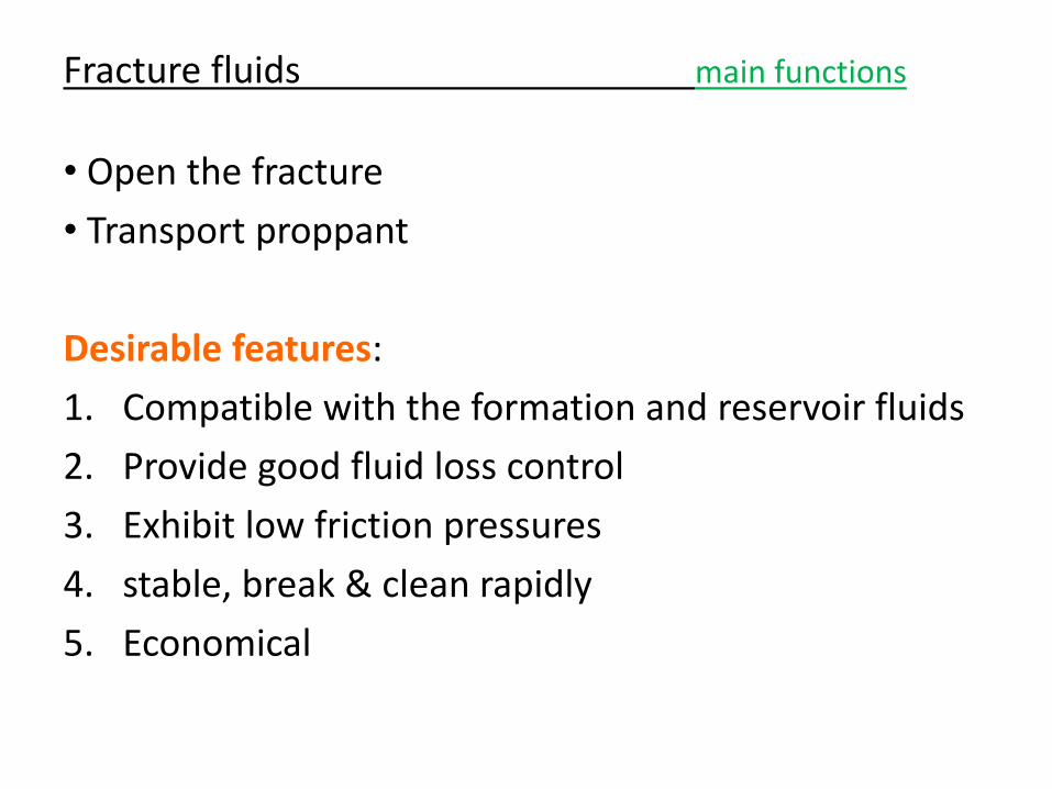
Pre-1950s oil-based
1950s water-based with GUAR
1969 First crosslinked GUAR (with 10% oil)
1970s HPG gelling agent
70% of treatments are water-based
Currently 25% are energized
5% are oil-based
Fracture fluids history
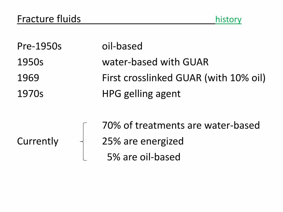
Water-based fluids Advantages: low cost, high performance, ease of handling Disadvantages: water sensitive formations, damage due to polymers Polymers – to viscosify fluids 1. GUAR – high molecular weight, long-chained sugars…natural (6-
10% residue) 2. HPG – chemically-treated guar, cleaner (2-4% residue) 3. HEC – cellulose derivatives
Fracture fluids fluid types
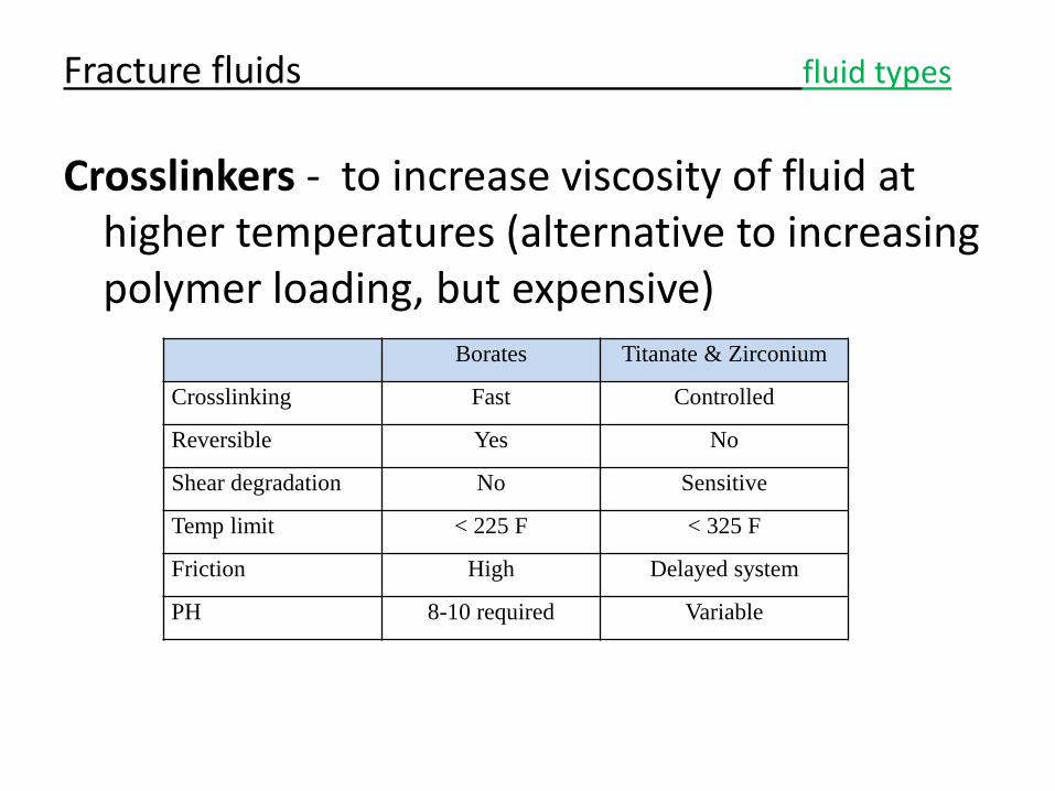
Crosslinkers - to increase viscosity of fluid at higher temperatures (alternative to increasing polymer loading, but expensive)
Fracture fluids fluid types
Borates Titanate & Zirconium
Crosslinking Fast Controlled
Reversible Yes No
Shear degradation No Sensitive
Temp limit < 225 F < 325 F
Friction High Delayed system
PH 8-10 required Variable
• An increase in T or pH will accelerate the crosslink reaction
• If crosslinking is too rapid then higher friction pressure and shear degradation occurs.
• If crosslinking too slow then proppant may settle in wellbore
• Desirable to have crosslink time = fluid time in wellbore
• Dual crosslink system – Fast to ensure adequate viscosity at perfs – Slow ensures viscous fluid in fractures
Fracture fluids fluid types
Oil-based fluids
Advantage:
– Application to water sensitive formations
Disadvantages:
– Costly
– environmental and safety concerns
– Quality of gels is poor and residue is high
Fracture fluids fluid types
Foamed fluids
• Addition of CO2 or N2 to base fluid
• Foam Quality – volume of frac fluid that is foam
– Range is 60 to 90 quality foam to be stable and have sufficient viscosity
– Typical is 70 quality
Fracture fluids fluid types
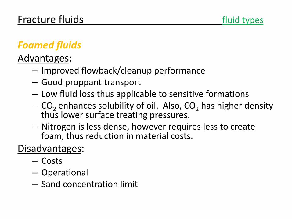
Foamed fluids Advantages:
– Improved flowback/cleanup performance – Good proppant transport – Low fluid loss thus applicable to sensitive formations – CO2 enhances solubility of oil. Also, CO2 has higher density
thus lower surface treating pressures. – Nitrogen is less dense, however requires less to create
foam, thus reduction in material costs.
Disadvantages: – Costs – Operational – Sand concentration limit
Fracture fluids fluid types
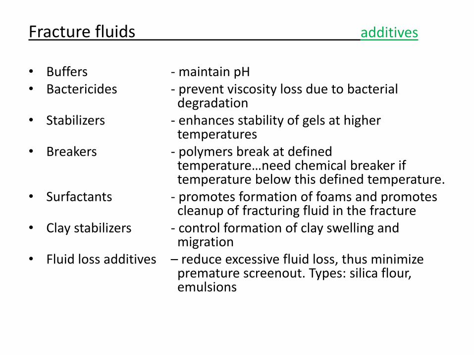
• Buffers - maintain pH • Bactericides - prevent viscosity loss due to bacterial
degradation • Stabilizers - enhances stability of gels at higher
temperatures • Breakers - polymers break at defined
temperature…need chemical breaker if temperature below this defined temperature.
• Surfactants - promotes formation of foams and promotes cleanup of fracturing fluid in the fracture
• Clay stabilizers - control formation of clay swelling and migration
• Fluid loss additives – reduce excessive fluid loss, thus minimize premature screenout. Types: silica flour, emulsions
Fracture fluids additives
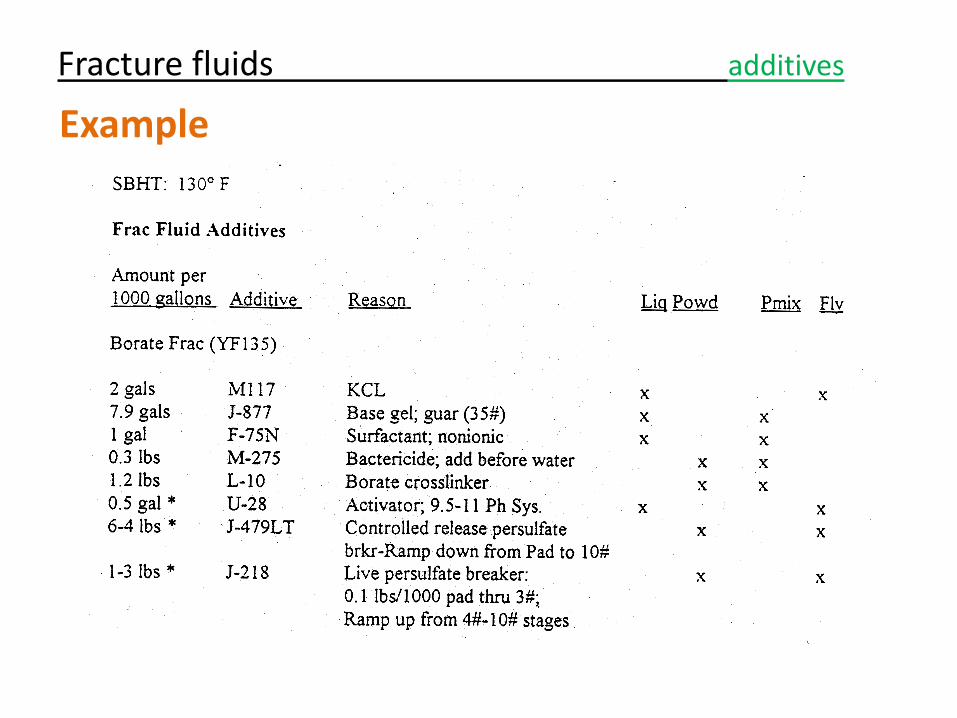
Example
Fracture fluids additives
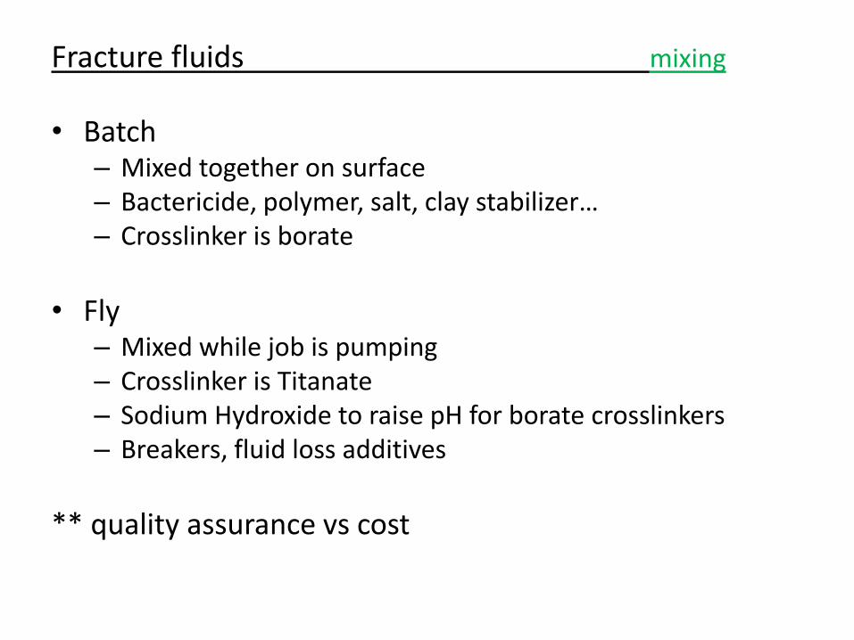
• Batch – Mixed together on surface – Bactericide, polymer, salt, clay stabilizer… – Crosslinker is borate
• Fly
– Mixed while job is pumping – Crosslinker is Titanate – Sodium Hydroxide to raise pH for borate crosslinkers – Breakers, fluid loss additives
** quality assurance vs cost
Fracture fluids mixing
1. Formation temperature and fluid rheology
2. Treatment volume and rate
3. Type of formation
4. Fluid loss control requirements
5. Formation sensitivity to fluids
6. Pressure
7. Depth
8. Type of proppant
9. Fluid Breaking requirements
Fracture fluids design criteria
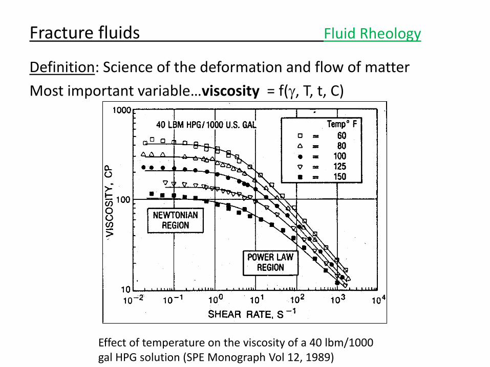
Definition: Science of the deformation and flow of matter
Most important variable…viscosity = f(g, T, t, C)
Fracture fluids Fluid Rheology
Effect of temperature on the viscosity of a 40 lbm/1000 gal HPG solution (SPE Monograph Vol 12, 1989)
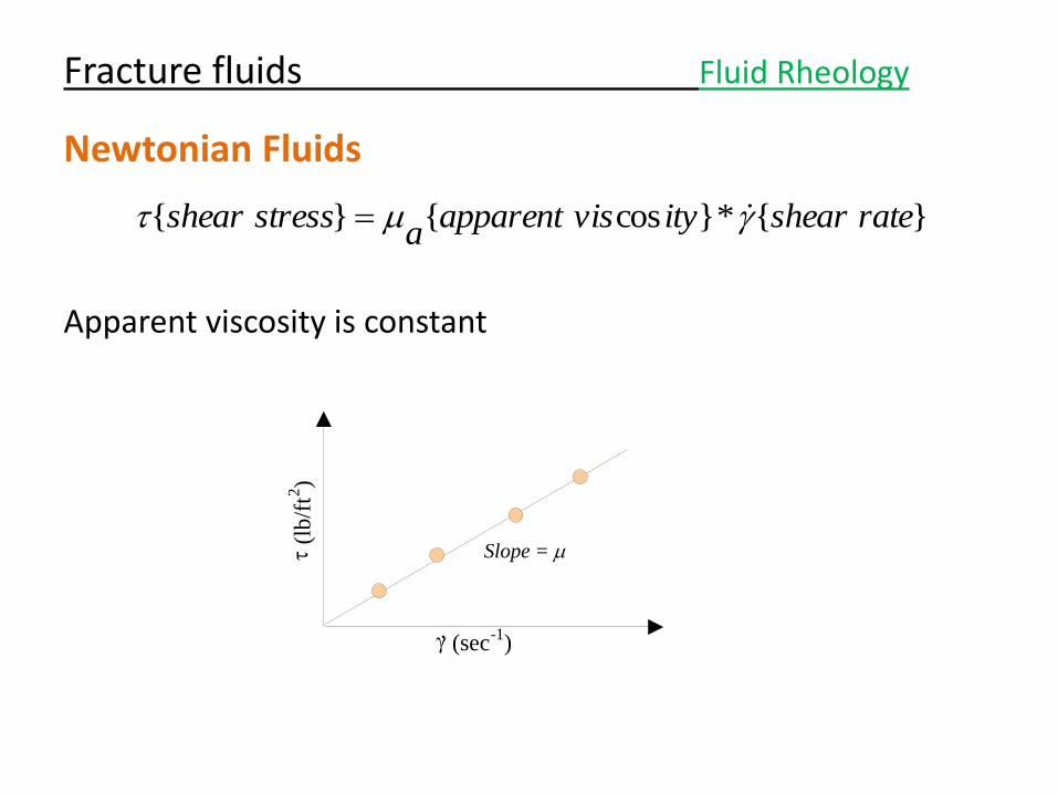
Newtonian Fluids
Apparent viscosity is constant
Fracture fluids Fluid Rheology
}{*}cos{}{ rateshearityvisapparenta
stressshear g
g (sec - 1 )
.
(l
b/f
t 2 )
Slope =
Fracture fluids Fluid Rheology
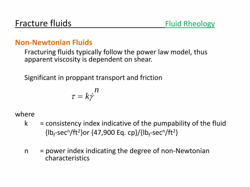
Non-Newtonian Fluids Fracturing fluids typically follow the power law model, thus
apparent viscosity is dependent on shear. Significant in proppant transport and friction where k = consistency index indicative of the pumpability of the fluid {lbf-secn/ft2}or {47,900 Eq. cp}/{lbf-secn/ft2} n = power index indicating the degree of non-Newtonian
characteristics
nkg
Fracture fluids Fluid Rheology
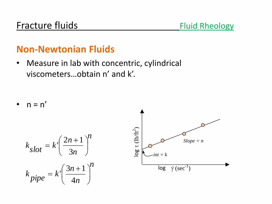
Non-Newtonian Fluids
• Measure in lab with concentric, cylindrical viscometers…obtain n’ and k’.
• n = n’
g (sec-1
) .
(l
b/f
t2)
Slope = n
int = k
n
n
nk
pipek
n
n
nk
slotk
4
13'
3
12'
log
log
Fracture fluids Fluid Rheology
Non-Newtonian Fluids
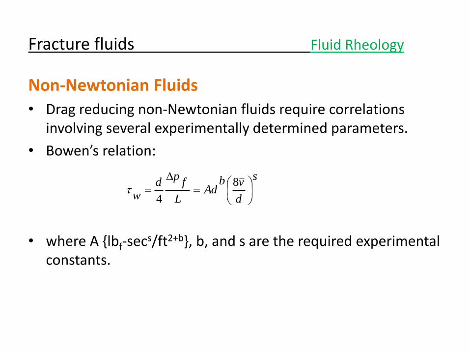
• Drag reducing non-Newtonian fluids require correlations involving several experimentally determined parameters.
• Bowen’s relation:
• where A {lbf-secs/ft2+b}, b, and s are the required experimental constants.
s
d
vbAd
L
fp
dw
8
4
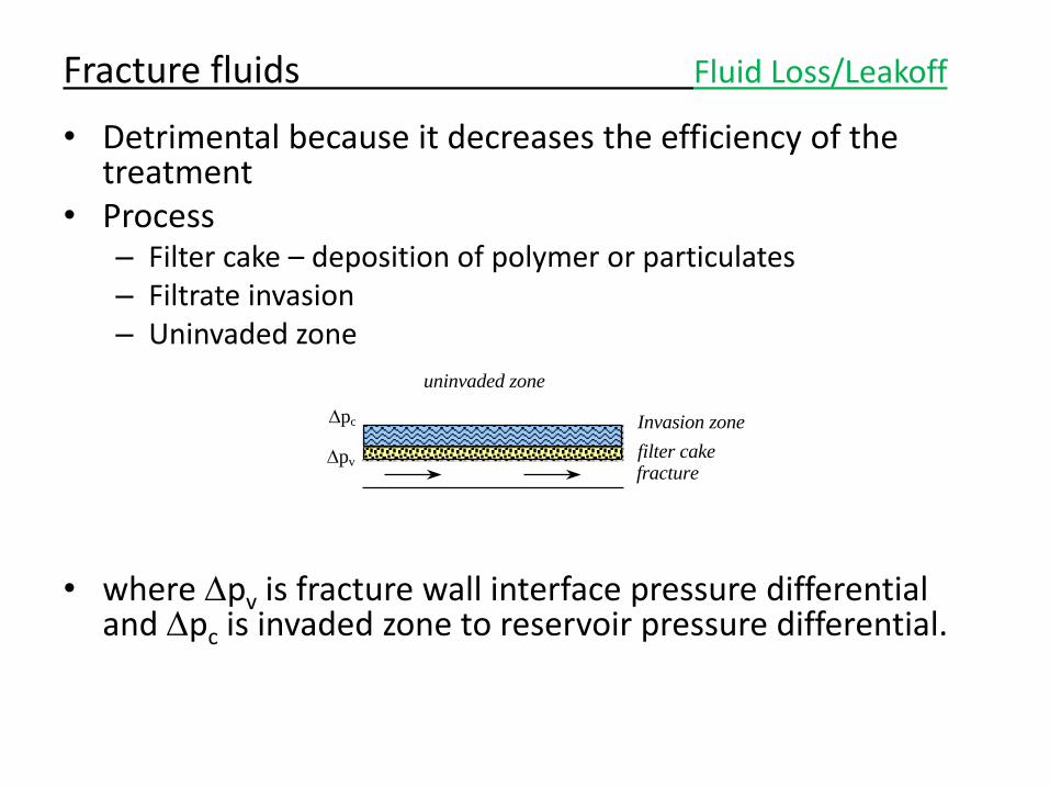
• Detrimental because it decreases the efficiency of the treatment
• Process – Filter cake – deposition of polymer or particulates – Filtrate invasion – Uninvaded zone
• where pv is fracture wall interface pressure differential
and pc is invaded zone to reservoir pressure differential.
Fracture fluids Fluid Loss/Leakoff
fracture
uninvaded zone
filter cake
Invasion zone pc
pv
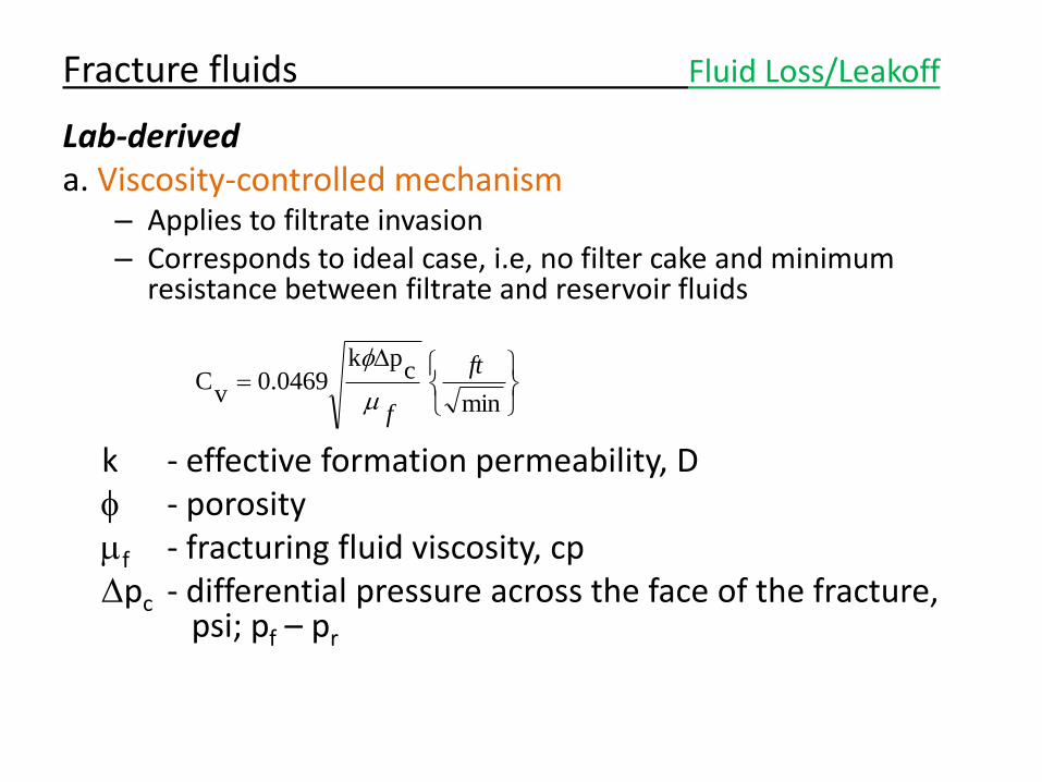
Lab-derived a. Viscosity-controlled mechanism
– Applies to filtrate invasion – Corresponds to ideal case, i.e, no filter cake and minimum
resistance between filtrate and reservoir fluids
k - effective formation permeability, D f - porosity f - fracturing fluid viscosity, cp pc - differential pressure across the face of the fracture,
psi; pf – pr
Fracture fluids Fluid Loss/Leakoff
min
cpk
0.0469v
Cft
f
f
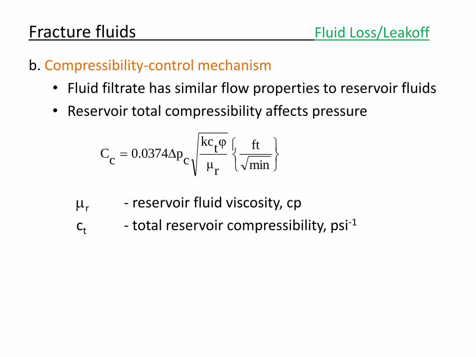
b. Compressibility-control mechanism
• Fluid filtrate has similar flow properties to reservoir fluids
• Reservoir total compressibility affects pressure
r - reservoir fluid viscosity, cp
ct - total reservoir compressibility, psi-1
Fracture fluids Fluid Loss/Leakoff
min
ft
rμ
φt
kc
cp0.0374
cC
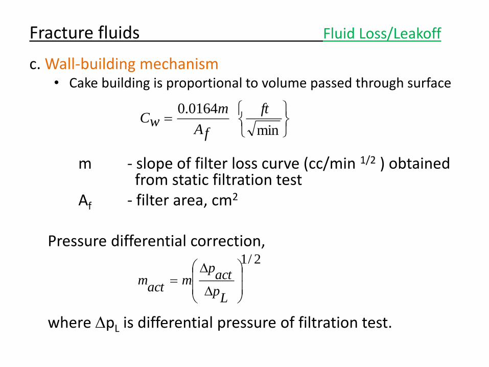
c. Wall-building mechanism • Cake building is proportional to volume passed through surface
m - slope of filter loss curve (cc/min 1/2 ) obtained
from static filtration test Af - filter area, cm2 Pressure differential correction, where pL is differential pressure of filtration test.
Fracture fluids Fluid Loss/Leakoff
min
0164.0 ft
fA
mwC
2/1
Lp
actp
mact
m
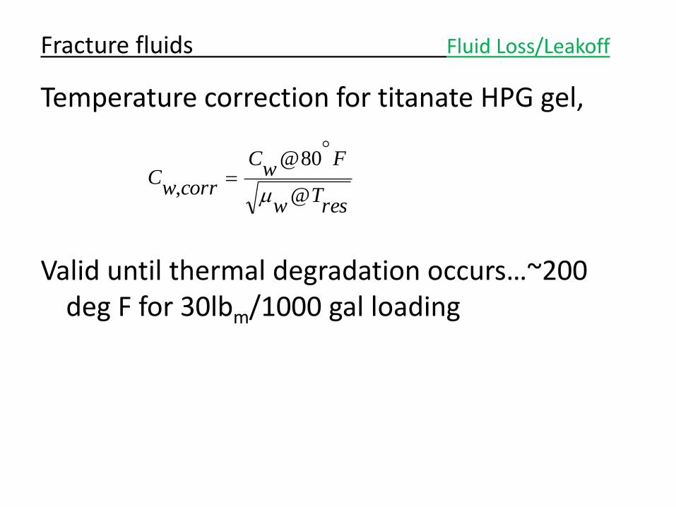
Temperature correction for titanate HPG gel,
Valid until thermal degradation occurs…~200 deg F for 30lbm/1000 gal loading
Fracture fluids Fluid Loss/Leakoff
resT
w
Fw
C
corrwC
@
80@
,
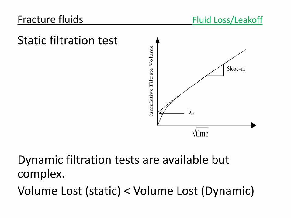
Static filtration test
Dynamic filtration tests are available but complex.
Volume Lost (static) < Volume Lost (Dynamic)
Fracture fluids Fluid Loss/Leakoff
Cu
mu
lati
ve F
iltr
ate
Vo
lum
e
Slope=m
bint
time
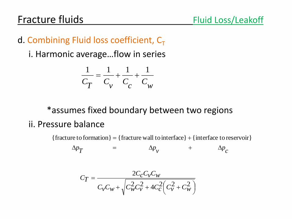
d. Combining Fluid loss coefficient, CT
i. Harmonic average…flow in series
*assumes fixed boundary between two regions
ii. Pressure balance
Fracture fluids Fluid Loss/Leakoff
wC
cC
vC
TC
1111
cp
vp
Tp
reservoir} to{interface interface} to wall{fractureformation} to{fracture
222422
2
wCvCcCvCwCwCvC
wCvCcCTC
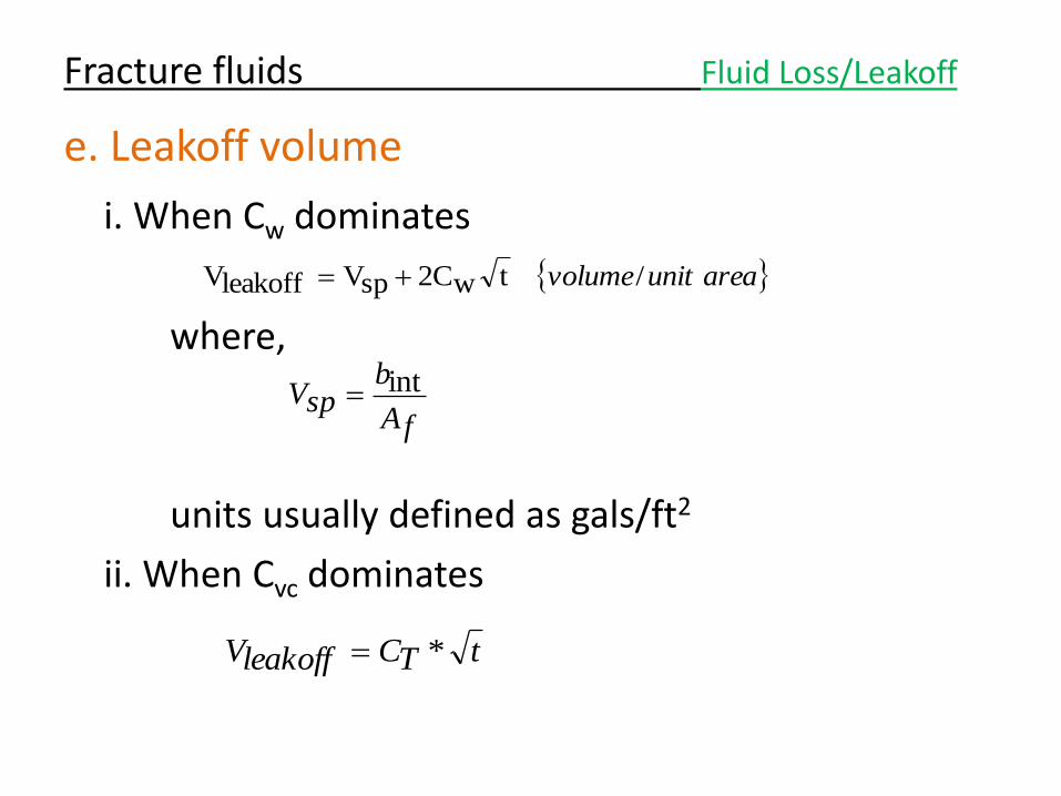
e. Leakoff volume
i. When Cw dominates
where,
units usually defined as gals/ft2
ii. When Cvc dominates
Fracture fluids Fluid Loss/Leakoff
areaunitvolume/tw2CspVleakoffV
fA
bspV int
tTCleakoffV *
Fracture fluids Fluid Loss/Leakoff
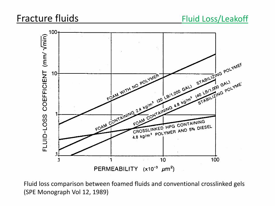
Fluid loss comparison between foamed fluids and conventional crosslinked gels (SPE Monograph Vol 12, 1989)
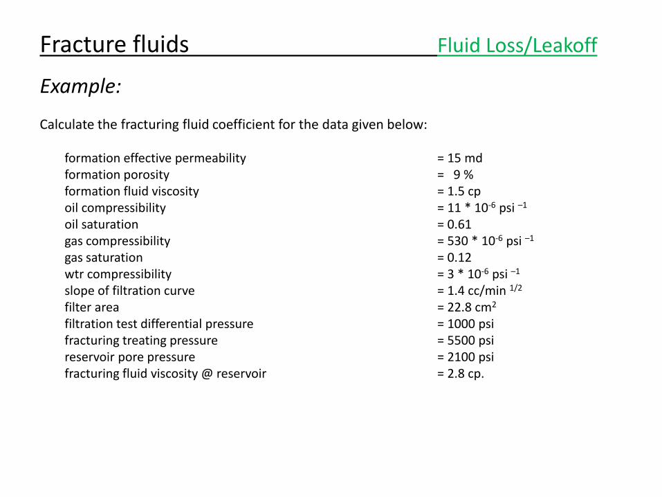
Example:
Calculate the fracturing fluid coefficient for the data given below: formation effective permeability = 15 md formation porosity = 9 % formation fluid viscosity = 1.5 cp oil compressibility = 11 * 10-6 psi –1 oil saturation = 0.61 gas compressibility = 530 * 10-6 psi –1 gas saturation = 0.12 wtr compressibility = 3 * 10-6 psi –1 slope of filtration curve = 1.4 cc/min 1/2 filter area = 22.8 cm2 filtration test differential pressure = 1000 psi fracturing treating pressure = 5500 psi reservoir pore pressure = 2100 psi fracturing fluid viscosity @ reservoir = 2.8 cp.
Fracture fluids Fluid Loss/Leakoff
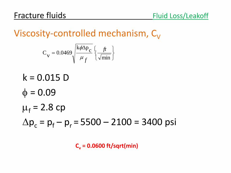
Viscosity-controlled mechanism, CV
k = 0.015 D
f = 0.09
f = 2.8 cp
pc = pf – pr = 5500 – 2100 = 3400 psi
Fracture fluids Fluid Loss/Leakoff
min
cpk
0.0469v
Cft
f
f
Cv = 0.0600 ft/sqrt(min)
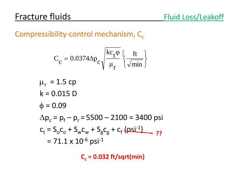
Compressibility-control mechanism, Cc
r = 1.5 cp
k = 0.015 D
f = 0.09
pc = pf – pr = 5500 – 2100 = 3400 psi
ct = Soco + Swcw + Sgcg + cf {psi-1}
= 71.1 x 10⁻⁶ psi-1
Fracture fluids Fluid Loss/Leakoff
min
ft
rμ
φt
kc
cp0.0374
cC
Cc = 0.032 ft/sqrt(min)
??
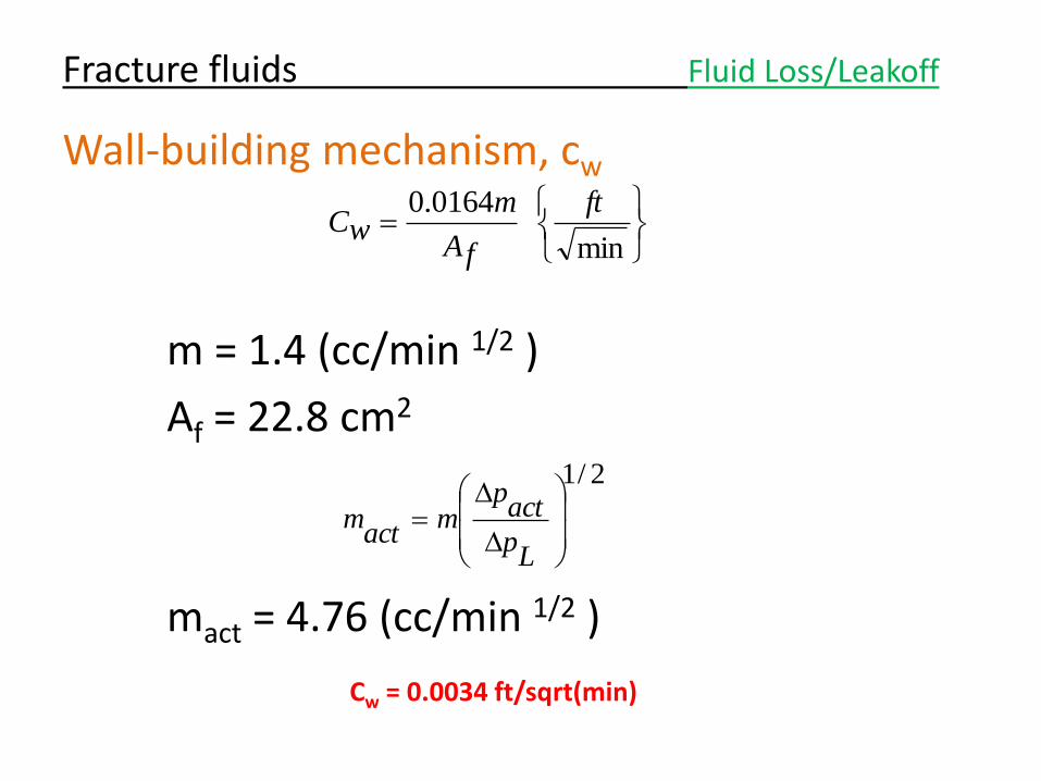
Wall-building mechanism, cw
m = 1.4 (cc/min 1/2 )
Af = 22.8 cm2
mact = 4.76 (cc/min 1/2 )
Fracture fluids Fluid Loss/Leakoff
min
0164.0 ft
fA
mwC
2/1
Lp
actp
mact
m
Cw = 0.0034 ft/sqrt(min)
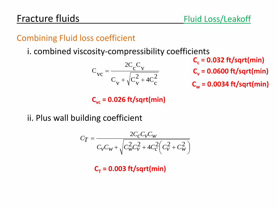
Combining Fluid loss coefficient
i. combined viscosity-compressibility coefficients
ii. Plus wall building coefficient
Fracture fluids Fluid Loss/Leakoff
222422
2
wCvCcCvCwCwCvC
wCvCcCTC
2c
C42v
Cv
C
vC
cC2
vcC
Cv = 0.0600 ft/sqrt(min)
Cc = 0.032 ft/sqrt(min)
Cw = 0.0034 ft/sqrt(min)
Cvc = 0.026 ft/sqrt(min)
CT = 0.003 ft/sqrt(min)
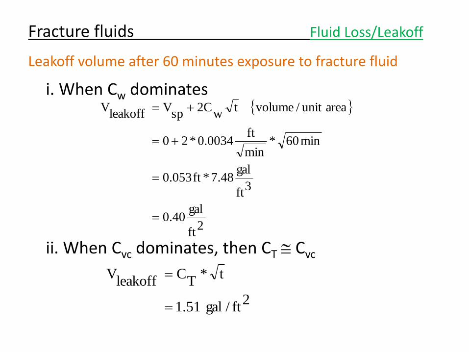
Leakoff volume after 60 minutes exposure to fracture fluid
i. When Cw dominates
ii. When Cvc dominates, then CT Cvc
Fracture fluids Fluid Loss/Leakoff
2ft
gal40.0
3ft
gal48.7*ft053.0
min60*min
ft0034.0*20
areaunit/volumetw
2Csp
Vleakoff
V
2ft/gal51.1
t*T
Cleakoff
V
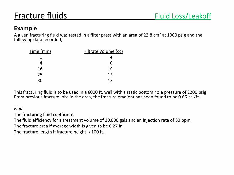
Example A given fracturing fluid was tested in a filter press with an area of 22.8 cm2 at 1000 psig and the following data recorded, Time (min) Filtrate Volume (cc) 1 4 4 6 16 10 25 12 30 13 This fracturing fluid is to be used in a 6000 ft. well with a static bottom hole pressure of 2200 psig. From previous fracture jobs in the area, the fracture gradient has been found to be 0.65 psi/ft. Find: The fracturing fluid coefficient The fluid efficiency for a treatment volume of 30,000 gals and an injection rate of 30 bpm. The fracture area if average width is given to be 0.27 in. The fracture length if fracture height is 100 ft.
Fracture fluids Fluid Loss/Leakoff
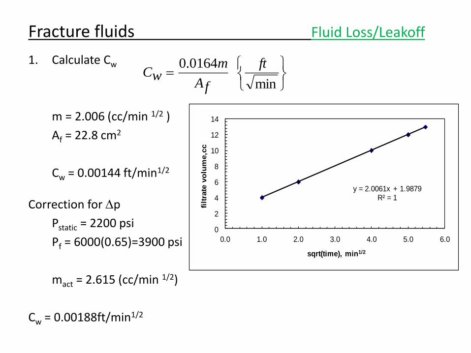
1. Calculate Cw
m = 2.006 (cc/min 1/2 )
Af = 22.8 cm2
Cw = 0.00144 ft/min1/2
Correction for p
Pstatic = 2200 psi
Pf = 6000(0.65)=3900 psi
mact = 2.615 (cc/min 1/2)
Cw = 0.00188ft/min1/2
Fracture fluids Fluid Loss/Leakoff
y = 2.0061x + 1.9879R² = 1
0
2
4
6
8
10
12
14
0.0 1.0 2.0 3.0 4.0 5.0 6.0
filt
rate
vo
lum
e,c
c
sqrt(time), min1/2
min
0164.0 ft
fA
mwC
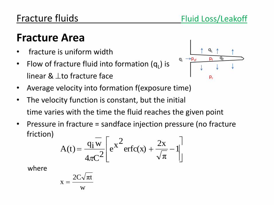
Fracture Area • fracture is uniform width
• Flow of fracture fluid into formation (qL) is
linear & to fracture face
• Average velocity into formation f(exposure time)
• The velocity function is constant, but the initial
time varies with the time the fluid reaches the given point
• Pressure in fracture = sandface injection pressure (no fracture friction)
where
Fracture fluids Fluid Loss/Leakoff
1
π
2xerfc(x)
2xe2C4
wiqA(t)
w
πt2Cx
qi qf
qL
psf pf
pr
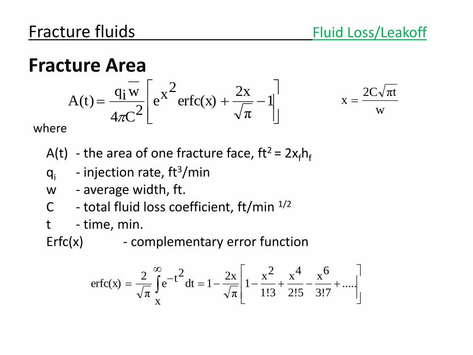
Fracture Area
where
A(t) - the area of one fracture face, ft2 = 2xfhf
qi - injection rate, ft3/min w - average width, ft. C - total fluid loss coefficient, ft/min 1/2 t - time, min. Erfc(x) - complementary error function
Fracture fluids Fluid Loss/Leakoff
1
π
2xerfc(x)
2xe2C4
wiqA(t)
w
πt2Cx
.....
3!7
6x
2!5
4x
1!3
2x1
π
2x1dt
x
2teπ
2erfc(x)
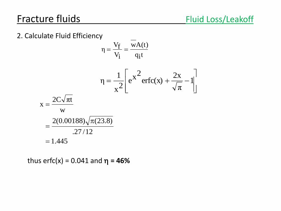
2. Calculate Fluid Efficiency
thus erfc(x) = 0.041 and h = 46%
Fracture fluids Fluid Loss/Leakoff
tiq
A(t)w
iV
fVη
1
π
2xerfc(x)
2xe2x
1η
445.1
12/27.
)8.23()00188.0(2
w
πt2Cx
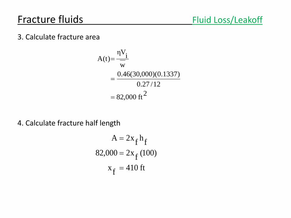
3. Calculate fracture area
4. Calculate fracture half length
Fracture fluids Fluid Loss/Leakoff
2ft000,82
12/27.0
)1337.0)(000,30(46.0
w
iηV
A(t)
ft410f
x
)100(f
x2000,82
fh
fx2A
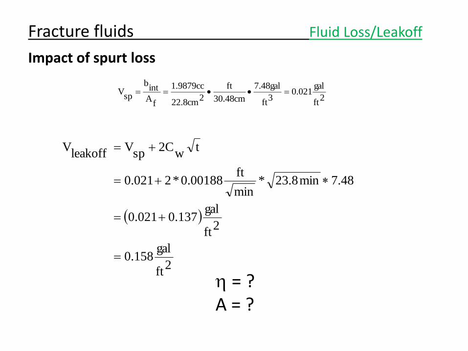
Impact of spurt loss
h = ? A = ?
Fracture fluids Fluid Loss/Leakoff
2ft
gal021.0
3ft
gal48.7
cm48.30
ft
2cm8.22
cc9879.1
fA
intb
spV
2ft
gal158.0
2ft
gal137.0021.0
48.7min8.23*min
ft00188.0*2021.0
tw
2Csp
Vleakoff
V
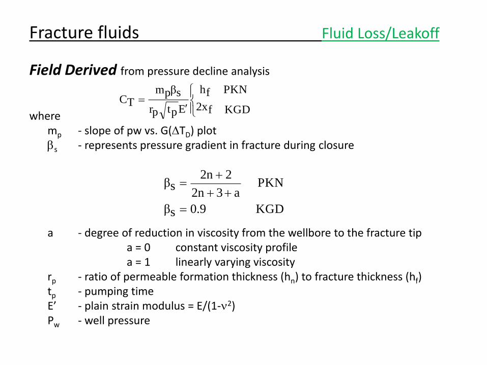
Field Derived from pressure decline analysis
where mp - slope of pw vs. G(TD) plot bs - represents pressure gradient in fracture during closure a - degree of reduction in viscosity from the wellbore to the fracture tip a = 0 constant viscosity profile a = 1 linearly varying viscosity rp - ratio of permeable formation thickness (hn) to fracture thickness (hf) tp - pumping time E’ - plain strain modulus = E/(1-n2) Pw - well pressure
KGDf2x
PKNfh
Eptpr
sβpmTC
KGD0.9sβ
PKNa32n
22nsβ
Fracture fluids Fluid Loss/Leakoff
Conversion of Laboratory Data to a Field Leakoff Coefficient
1. Use a lab-derived spurt loss and Cw that is characteristic of the fluid package and for a specific formation permeability and temperature.
Most common… 2. Use a simulator to handle multiple fluid
parameters 3. Use a model to account for variable downhole
conditions
Fracture fluids Fluid Loss/Leakoff
Comparison of Laboratory and Field Leakoff Coefficients
Observation: In general, Cfield > CLab
Fracture fluids Fluid Loss/Leakoff