Fractal Geometry Applied To Fracture (Part 3)
37
Fractal Geometry Applied To Fracture (Part 3) J. J. Mecholsky, Jr. Materials Science & Engineering Department University of Florida Gainesville, FL 32611-6400 [email protected] Glass Tutorial Series: prepared for and produced by the International Material Institute for New Functionality in Glass An NSF sponsored program – material herein not for sale Available at www.lehigh.edu/imi
Transcript of Fractal Geometry Applied To Fracture (Part 3)

Fractal Geometry Applied To Fracture (Part 3)J. J. Mecholsky, Jr.Materials Science & Engineering DepartmentUniversity of FloridaGainesville, FL 32611-6400
[email protected] Tutorial Series: prepared for and produced by theInternational Material Institute for New Functionality in GlassAn NSF sponsored program – material herein not for sale Available at www.lehigh.edu/imi

Technical Approach
• Experimental determination and comparison of parameters obtained in MO and MD Modeling, i.e., a0 and D*
• Molecular Orbital (MO) Modeling of Fracture - determines a0.
• Molecular Dynamics (MD) Modeling of Fracture - determines D* (e.g. in Si)

cf. Varsheneya, Fundamentals of Inorganic Glasses
(After Bell and Dean, Nature 212, 1354 [1966])
Bell & Dean Model Used for MO Calculations

cf. Varsheneya, Fundamentals of Inorganic Glasses (after T. F. Soules, Glass Sci & Tech 4A, 318)

cf. Varsheneya, Fundamentals of Inorganic Glasses
Simulated SiO2 Δ displ.= 1 Å
MO Simulates Bond Breaking At The Crack Tip


aa
c
c'
Strain Can Be Measured In Model
a0 = a / ε
= c a / c’-c
J. Non-Crystalline Solids 260 (1999) 99-108.

Modeling and Experimental Results Agree
0
5
10
15
0 2 4 6 8 10 12
a0 [A] Theoretical
a 0 [ Α
] Exp
erim
enta
l
Si(110){100} ZnS
Si (100){110}
silica
alumina
J. K. West, J. J. Mecholsky, Jr, and L. L. Hench, “The Quantum and Fractal Geometry of Brittle Fracture”, J. Non-Crystalline Solids 260 (1999) 99-108.
a0 = 2γ/ (ED*)

Material Class a0 (Å)
Single CrystalsGlassesGlass CeramicsPolycrystalline CeramicsPolymers
1-1010-2020-803-102700-14000
a0 Is Related To Structure

Fractal Geometry Applied To Fracture (Part 4)J. J. Mecholsky, Jr.Materials Science & Engineering DepartmentUniversity of FloridaGainesville, FL 32611-6400
[email protected] Tutorial Series: prepared for and produced by theInternational Material Institute for New Functionality in GlassAn NSF sponsored program – material herein not for sale Available at www.lehigh.edu/imi

FSA Can Be Applied To Single Crystals
Single Crystal Silicon

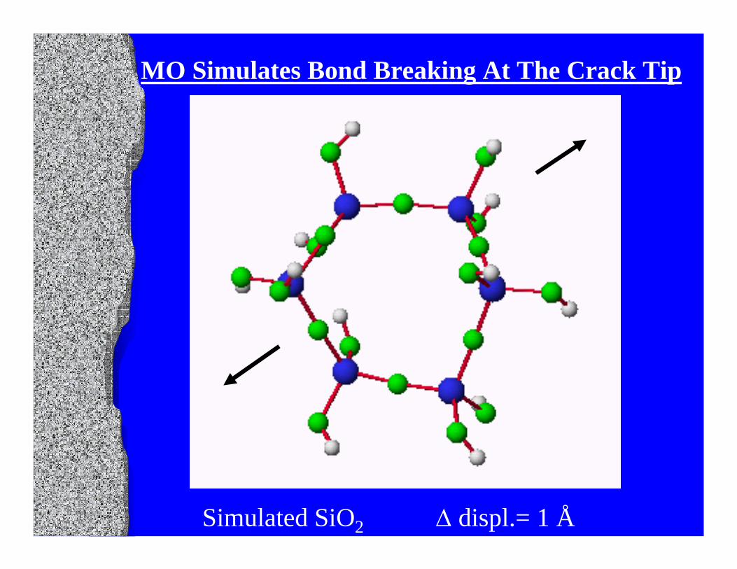
Simulated Fracture Can Form Fracture Surface

Simulated Fracture Can Form Fracture Surface

Simulated Fracture Can Form Fracture Surface
Simulated Fracture Can Form Fracture Surface

Surface Can Be Created From MD Simulation

Slit Island Contour Can Be Made From 3-D Map

Log (Ruler Length)
Slope = -D*Log Length (A-B)
B
A
FRACTAL DIMENSION IS MEASURED ALONG CONTOUR
A-B = Slit Island Contour
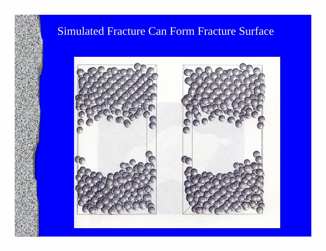
Material Fracture Plane/Surface
KIC (MPam1/2) Fractal Dimension (Experimental)
Fractal Dimension (MD Simulation)
Si {100}/{110} 1.26 ± 0.06 2.16 ± 0.04 2.16 ± 0.06
Si {110}/{100} 1.23 ± 0.08 2.10 ± 0.04 2.11 ± 0.05
Si {111}/{110} 1.17 ± 0.08 2.06 ± 0.02 2.09 ± 0.04
Silica (amorphous) 0.75 2.11± 0.02 2.1
MD Simulations & Experimental Results Agree
Y. L. Tsai, T. P. Swiler , J. H. Simmons and J. J. Mecholsky, Jr., in Computational Modelling of Materials and Processing, J. H. Simmons, et al. (eds) The Am. Cer. Society, Ceram. Trans. 69 (1997) 217.


Fracture Is A Fractal Process• Fracture transcends many length scales;
Self-similar (or self-affine), scale invariant & characterized by D*.
• Hypothesis: 2γ = [a0 E D*]
• Observations seem to support the hypothesis.c/r = D* ; γ ∝ ED*
(D* is a geometric & energy scaling factor.)(a0 is a fracture surface structural element)
• MD & MO modeling provide framework for understanding macroscopic observations

Model Scale ExperimentMO sub-atomic fractoemissionAb initio atomic AFMQuantum nano STMMechanics Raman
FluorescenceMD micro crack velocityMonte Carlo SEM Finite diff. Meso AFM
FEM Macro fractographyfracture mechanics
Many Tools Are Needed for Unified Fracture Theory
Fractal
Geometry
Fracture Process

Summary• At the atomic level, quantum mechanics
describes the fracture process as a ring contraction process dictated by minimum energy and availability of free volume.
• On the molecular scale, MD modeling describes creation of the fracture surface.• On the macroscopic scale, mirror, mist & hackle form & c/r = D*• At all length scales, 2γ = [a0 E D*]

Critical Questions Need To Be Asked• What are the energetic & geometric steps
to fracture?• Is a flat fracture (of primary bonds) possible
above absolute zero? What is bond rupture?
• Is roughness a meaningful parameter in fracture?
• How does energy scale? • How does a crack propagate at all length scales?

CONCLUSIONS• Fractal fracture implies that the same
fracture process should be able to be observed at all length scales.
• Experimental data & analytical modeling have to be interactive to be successful.
• All models should be compared to (real) experimental data.
• Analytical models have to explain fractal nature of fracture, mirror, mist & hackle and crack branching.

σ
ε
Log v
Log K = Log (Yσ c ½)
U
rKc
Bond Breaking Leads to Characteristic Features

University of Florida, Gainesville FL