FPU® SYSTEMS OPERATION MANUAL (INCLUDING REPAIR …
48
BOH-PM-16-6 © 2021 BOH Environmental LLC Chapter 6 Rev. 0.00 FPU® SYSTEMS OPERATION MANUAL (INCLUDING REPAIR PARTS) EXPEDITIONARY BULK STORAGE SYSTEM (EBSS) CHAPTER 6 PARTS SUPPORTING INFORMATION
Transcript of FPU® SYSTEMS OPERATION MANUAL (INCLUDING REPAIR …

BOH-PM-16-6 © 2021 BOH Environmental LLC Chapter 6 Rev. 0.00
FPU® SYSTEMS OPERATION MANUAL (INCLUDING REPAIR PARTS)
EXPEDITIONARY BULK STORAGE SYSTEM (EBSS)
CHAPTER 6
PARTS SUPPORTING INFORMATION

BOH-PM-16-6 Chapter 6 Rev. 0.00
This page was intentionally left blank

0020 00
BOH-PM-16-6 Chapter 6 Rev. 0.00
0020 00-1
PARTS SUPPORTING INFORMATION
FPU® SYSTEMS OPERATION MANUAL (INCLUDING REPAIR PARTS)
EXPEDITIONARY BULK STORAGE SYSTEM (EBSS)
INTRODUCTION TO MAINTENANCE ALLOCATION CHART (MAC)
INTRODUCTION
FPU® SYSTEMS Recommended MAC
This introduction provides a general explanation of all maintenance and repair functions authorized at various maintenance levels under the standard Army Maintenance System concept.
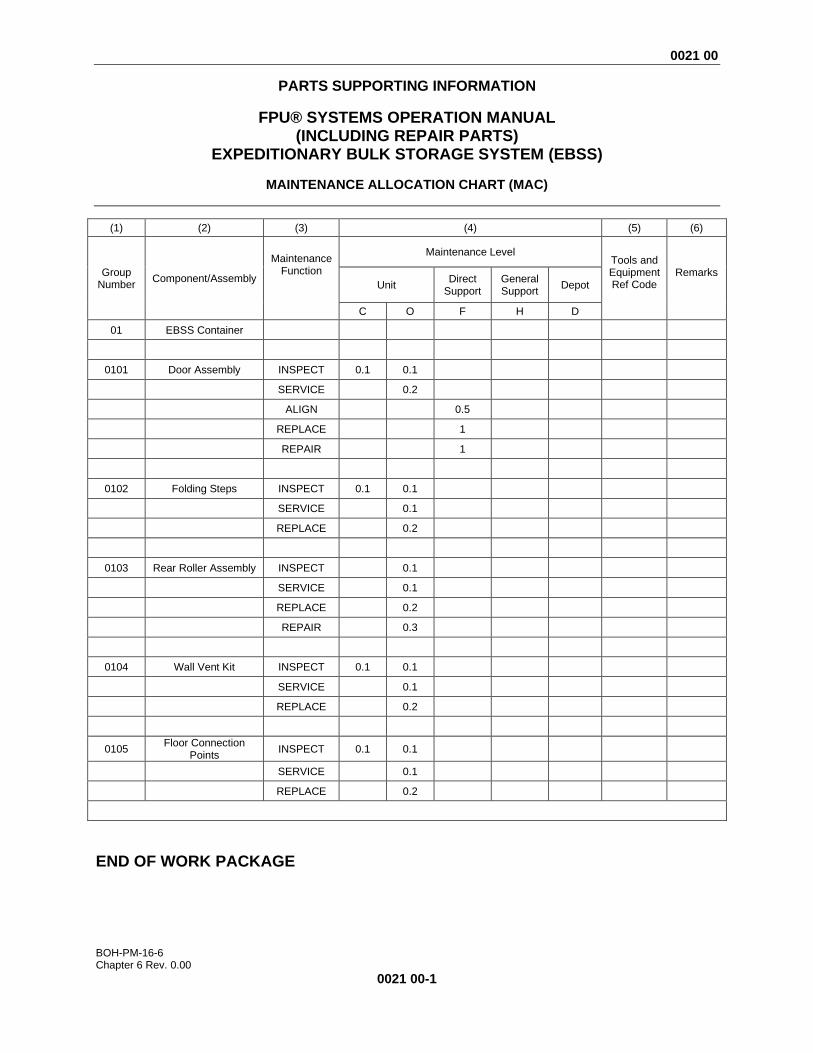
The MAC (WP 0021 00, Table 1, immediately following the introduction) designates overall authority and responsibility for the performance of maintenance functions on the EBSS container. The application of the maintenance functions to the EBSS container shall be consistent with the capacities and capabilities of the designated maintenance levels, which are shown on the MAC in column (4) as:
Unit – includes two sub columns, C (operator/crew) and O (unit) maintenance. Direct Support – includes an F sub column. General Support – includes an H sub column. Depot – includes a D sub column.
Maintenance Functions
Maintenance functions are limited to and defined as follows:
1. Inspect: To determine the serviceability of an item by comparing its physical and mechanical characteristics with established standards through examination (e.g., by sight, sound, or feel). This includes scheduled inspections.
2. Test: To verify serviceability by measuring the mechanical characteristics of an item and comparing those characteristics with prescribed standards on a scheduled basis, i.e., load testing of lift devices and hydrostatic testing of pressure hoses.
3. Service: Operations required periodically to keep an item in proper operating condition; e.g., to clean (includes decontaminate, when required), to preserve, to drain, to paint, or to replenish fuel, lubricants, chemical fluids, or gases.
4. Adjust: To maintain or regulate, within prescribed limits, by bringing into proper position, or by setting the operating characteristics to specific parameters.
5. Align: To adjust specified variable elements of an item to bring about optimum or desired performance.
6. Calibrate: To determine and cause corrections to be made or to be adjusted on instruments of test, measuring, and diagnostic equipment used in precision measurement. Consists of comparisons of two instruments, one of which is a certified standard of known accuracy, to detect and adjust any discrepancy in the accuracy of the instrument being compared.
7. Remove/Install: To remove and install the same item when required to perform service or other maintenance functions. Install may be the act of emplacing, seating, or fixing into position a spare, repair part, or module (component or assembly) in a manner to allow the proper functioning of an equipment or system.

0020 00
BOH-PM-16-6 Chapter 6 Rev. 0.00
0020 00-2
8. Replace: To remove an unserviceable item and install a serviceable counterpart in its place. "Replace" is authorized by the MAC and assigned maintenance level is shown as the third position code of the Source, Maintenance and Recoverability (SMR) code.
9. Repair: The application of maintenance services, including fault location/troubleshooting, removal/installation, disassembly/assembly procedures, and maintenance actions to identify troubles and restore serviceability to an item by correcting specific damage, fault, malfunction, or failure in a part, subassembly, module (component or assembly), end item, or system.
NOTE The following definitions are applicable to the “REPAIR” maintenance functions of
Service, Inspect, Test, Adjust, Align, Calibrate, and/or Replace:
Fault location/troubleshooting – The process of investigating and detecting the cause
of equipment malfunctioning; the act of isolating a fault within a system or Unit Under
Test (UUT).
Disassembly/Assembly – The step-by-step breakdown (taking apart) of a
spare/functional group coded item to the level of its least component, that is assigned
an SMR code for the level of maintenance under consideration (i.e., identified as
maintenance significant).
Actions – Welding, grinding, riveting, straightening, facing, machining, and/or
resurfacing.
10. Overhaul: That maintenance effort (service/action) prescribed to restore an item to a completely
serviceable/operational condition as required by maintenance standards in appropriate technical publications. Overhaul is normally the highest degree of maintenance performed by the Army. Overhaul does not normally return an item to like new condition.
11. Rebuild: Consists of those services/actions necessary for the restoration of unserviceable equipment
to a like new condition in accordance with original manufacturing standards. Rebuild is the highest degree of materiel maintenance applied to Army equipment. The rebuild operation includes the act of returning to zero those age measurements (e.g., hours/miles) considered in classifying Army equipment/components.
Explanation of Columns in the MAC Column (1) – Group Number. Column (1) lists Functional Group Code (FGC) numbers, the purpose of which is to identify maintenance significant components, assemblies, subassemblies, and modules with the Next Higher Assembly (NHA). Column (2) – Component/Assembly. Column (2) contains the item names of components, assemblies, subassemblies, and modules for which maintenance is authorized. Column (3) – Maintenance Function. Column (3) lists the functions to be performed on the item listed in column (2). (For a detailed explanation of these functions refer to “Maintenance Functions” outlined above).

0020 00
BOH-PM-16-6 Chapter 6 Rev. 0.00
0020 00-3
Column (4) – Maintenance Level. Column (4) specifies each level of maintenance authorized to perform each function listed in column (3), by indicating work time required (expressed as man-hours in whole hours or decimals) in the appropriate sub column. This work time figure represents the active time required to perform that maintenance function at the indicated level of maintenance. If the number or complexity of the tasks within the listed maintenance function varies at different maintenance levels, appropriate work time figures are to be shown for each level. The work time figure represents the average time required to restore an item (assembly, subassembly, component, module, end item, or system) to a serviceable condition under typical field operating conditions. This time includes preparation time (including any necessary disassembly/assembly time), troubleshooting/fault location time, and quality assurance time in addition to the time required to perform the specific tasks identified for the maintenance functions authorized in the MAC. The symbol designations for the various maintenance levels are as follows:
• C – Operator or crew maintenance
• O– Unit maintenance
• F – Direct Support maintenance
• L – Specialized repair activity (SRA)
• H – General support maintenance
• K – Commercial depot maintenance Column (5) – Tools and Equipment Reference Code. Column (5) specifies, by code, those common tool sets (not individual tools), common Test, Measurement and Diagnostic Equipment (TMDE), and special tools, special TMDE and special support equipment required to perform the designated function. Column (6) – Remarks Code. When applicable, this column contains a letter code, in alphabetical order
END OF WORK PACKAGE
BOH-PM-16-6 Chapter 6 Rev. 0.00
This page was intentionally left blank
0021 00
BOH-PM-16-6 Chapter 6 Rev. 0.00
0021 00-1
PARTS SUPPORTING INFORMATION
FPU® SYSTEMS OPERATION MANUAL (INCLUDING REPAIR PARTS)
EXPEDITIONARY BULK STORAGE SYSTEM (EBSS)
MAINTENANCE ALLOCATION CHART (MAC)
(1) (2) (3) (4) (5) (6)
Group
Number
Component/Assembly
Maintenance Function
Maintenance Level Tools and Equipment Ref Code
Remarks Unit
Direct Support
General Support
Depot
C O F H D
01 EBSS Container
0101 Door Assembly INSPECT 0.1 0.1
SERVICE 0.2
ALIGN 0.5
REPLACE 1
REPAIR 1
0102 Folding Steps INSPECT 0.1 0.1
SERVICE 0.1
REPLACE 0.2
0103 Rear Roller Assembly INSPECT 0.1
SERVICE 0.1
REPLACE 0.2
REPAIR 0.3
0104 Wall Vent Kit INSPECT 0.1 0.1
SERVICE 0.1
REPLACE 0.2
0105 Floor Connection
Points INSPECT 0.1 0.1
SERVICE 0.1
REPLACE 0.2
END OF WORK PACKAGE

BOH-PM-16-6 Chapter 6 Rev. 0.00
This page was intentionally left blank

0022 00
BOH-PM-16-6 Chapter 6 Rev. 0.00
0022 00-1
PARTS SUPPORTING INFORMATION
FPU® SYSTEMS OPERATION MANUAL (INCLUDING REPAIR PARTS)
EXPEDITIONARY BULK STORAGE SYSTEM (EBSS)
INTRODUCTION TO REPAIR PARTS & SPECIAL TOOL LIST
INTRODUCTION SCOPE This Repair Parts & Special Tools List (RPSTL) lists and authorizes spares and repair parts; special tools; special test, measurement, and diagnostic equipment (TMDE); and other special support equipment required for performance of Operator, Unit, and Direct Support maintenance of the Field Pack Up system (FPU SYSTEMS). It authorizes the requisitioning, issue, and disposition of spares, repair parts, and special tools as indicated by the Source, Maintenance, and Recoverability (SMR) codes. GENERAL In addition to the Introduction work package, this RPSTL is divided into the following work packages: 1. Repair Parts List Work Packages. See WP 0023. Work packages containing lists of spares and
repair parts authorized by this RPSTL for use in the performance of maintenance. These work packages also include parts which must be removed for replacement of the authorized parts. Parts lists are composed of functional groups in ascending alphanumeric sequence, with the parts in each group listed in ascending figure and item number sequence. Sending units, brackets, filters, and bolts are listed with the component they mount on. Bulk materials are listed by item name in FIG. BULK at the end of the work packages. Repair parts kits are listed separately in their own functional group and work package. Repair parts for reparable special tools are also listed in a separate work package. Items listed are shown on the associated illustrations.
2. Special Tools List Work Packages. NOT APPLICABLE TO THIS PRODUCT. Work packages
containing lists of special tools, special TMDE, and special support equipment authorized by this RPSTL (as indicated by Basis of Issue (BOI) information in the Description and Usable On Code (UOC) column). Tools that are components of common tool sets and/or Class VII are not listed
3. Cross-Reference Indexes Work Packages. See WP 0024 00 and WP 0025 00. There are two
cross-reference indexes work packages in this RPSTL: the National Stock Number (NSN) Index work package and the Part Number (P/N) Index work package. The National Stock Number Index work package refers you to the figure and item number. The Part Number Index work package refers you to the figure and item number.
0022 00
BOH-PM-16-6 Chapter 6 Rev. 0.00
0022 00-2
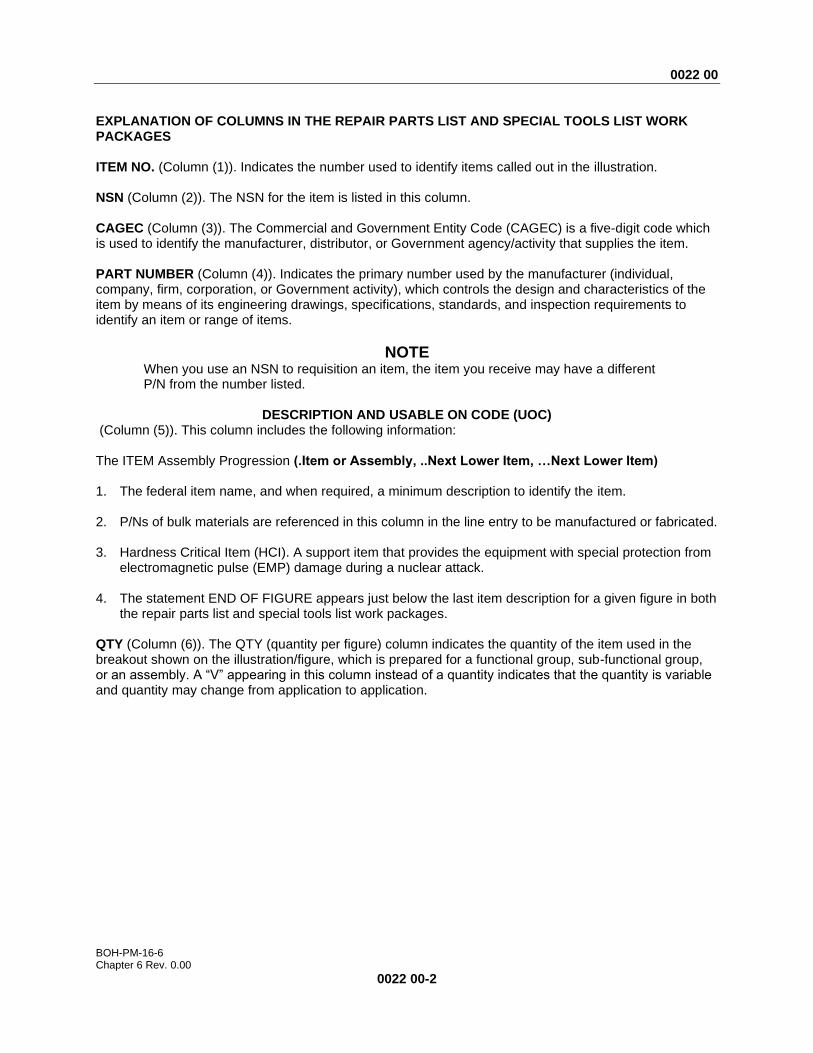
EXPLANATION OF COLUMNS IN THE REPAIR PARTS LIST AND SPECIAL TOOLS LIST WORK PACKAGES ITEM NO. (Column (1)). Indicates the number used to identify items called out in the illustration. NSN (Column (2)). The NSN for the item is listed in this column. CAGEC (Column (3)). The Commercial and Government Entity Code (CAGEC) is a five-digit code which is used to identify the manufacturer, distributor, or Government agency/activity that supplies the item. PART NUMBER (Column (4)). Indicates the primary number used by the manufacturer (individual, company, firm, corporation, or Government activity), which controls the design and characteristics of the item by means of its engineering drawings, specifications, standards, and inspection requirements to identify an item or range of items.
NOTE When you use an NSN to requisition an item, the item you receive may have a different P/N from the number listed.
DESCRIPTION AND USABLE ON CODE (UOC)
(Column (5)). This column includes the following information: The ITEM Assembly Progression (.Item or Assembly, ..Next Lower Item, …Next Lower Item) 1. The federal item name, and when required, a minimum description to identify the item. 2. P/Ns of bulk materials are referenced in this column in the line entry to be manufactured or fabricated. 3. Hardness Critical Item (HCI). A support item that provides the equipment with special protection from
electromagnetic pulse (EMP) damage during a nuclear attack. 4. The statement END OF FIGURE appears just below the last item description for a given figure in both
the repair parts list and special tools list work packages. QTY (Column (6)). The QTY (quantity per figure) column indicates the quantity of the item used in the breakout shown on the illustration/figure, which is prepared for a functional group, sub-functional group, or an assembly. A “V” appearing in this column instead of a quantity indicates that the quantity is variable and quantity may change from application to application.

0022 00
BOH-PM-16-6 Chapter 6 Rev. 0.00
0022 00-3
EXPLANATION OF CROSS-REFERENCE INDEXES WORK PACKAGES FORMAT AND COLUMNS.
1. National Stock Number (NSN) Index Work Package.
STOCK NUMBER Column. This column lists the NSN in National Item Identification Number (NIIN) sequence. The NIIN consists of the last nine digits of the NSN.
NSN When using this column to locate an item, ignore the first four digits of the NSN. However, the complete NSN should be used when ordering items by stock number.
(e.g.,5385-01-574-1476)
FIG. Column. This column lists the number of the figure where the item is identified/located. The figures are in numerical order in the repair parts list and special tools list work packages.
ITEM Column. The item number identifies the item associated with the figure listed in the adjacent FIG. Column. This item is also identified by the NSN listed on the same line.
2. Part Number (P/N) Index Work Package. P/Ns in this index are listed in ascending alphanumeric sequence (vertical AIDS of letter and number combinations which places the first letter or digit of each group in order A through Z, followed by the numbers 0 through 9 and each following letter or digit in like order).
PART NUMBER Column. Indicates the P/N assigned to the item.
FIG. Column. This column lists the number of the figure where the item is identified/located in the repair parts list and special tools list work packages.
ITEM Column. The item number is the number assigned to the item as it appears in the figure referenced in the adjacent figure number column.
SPECIAL INFORMATION
UOC. The UOC appears in the lower left corner of the Description Column heading. Usable On Codes are shown as “UOC . . .” in the Description Column (justified left) on the first line under the applicable item/nomenclature. None coded items are applicable to all models. Identification of the UOCs used in this RPSTL are:
CODE Usable On FAA Model EBSS GREEN – Forest Green FAB Model EBSS TAN – Desert Sand
Fabrication Instructions. Bulk materiel required to manufacture items are listed in the bulk materiel functional group of this RPSTL. Part numbers for bulk materiel are also referenced in the Description Column of the line item entry for the item to be manufactured/fabricated. Detailed fabrication instructions for items source Coded to be manufactured or fabricated are found in: Not Applicable.
Index Numbers. Items which have the word BULK in the figure column will have an index number shown in the item number column. This index number is a cross-reference between the NSN and P/N index work packages and the bulk materiel list in the repair parts list work package.
Illustrations List. The illustrations in this RPSTL contain unit and direct support authorized items. The tabular list in the repair parts list work package contains only those parts coded “O” and “F” in the third

0022 00
BOH-PM-16-6 Chapter 6 Rev. 0.00
0022 00-4
position of the SMR code, therefore, there may be a break in the item number sequence. HOW TO LOCATE REPAIR PARTS A. When NSNs or P/Ns Are Not Known.
1. Using the table of contents, determine the assembly group to which the item belongs. This is necessary since figures are prepared for assembly groups and subassembly groups, and lists are divided into the same groups.
2. Find the figure covering the functional group or the sub functional group to which the item
belongs.
3. Identify the item on the figure and note the number(s).
4. Look in the repair parts list work packages for the figure and item numbers. The NSNs and part numbers are on the same line as the associated item numbers.
B. When NSN Is Known.
1. If you have the NSN, look in the STOCK NUMBER column of the NSN index work package. The NSN is arranged in NIIN sequence. Note the figure and item number next to the NSN.
2. Turn to the figure and locate the item number. Verify that the item is the one you are looking for.
C. When the P/N Is Known.
1. If you have the P/N and not the NSN, look in the PART NUMBER column of the P/N index work package. Identify the figure and item number.
2. Look up the item on the figure in the applicable repair parts list work package.
END OF WORK PACKAGE
0023 00
BOH-PM-16-6 Chapter 6 Rev. 0.00
0023 00-1
PARTS SUPPORTING INFORMATION
FPU® SYSTEMS OPERATION MANUAL (INCLUDING REPAIR PARTS)
EXPEDITIONARY BULK STORAGE SYSTEM (EBSS)
REPAIR PARTS LIST
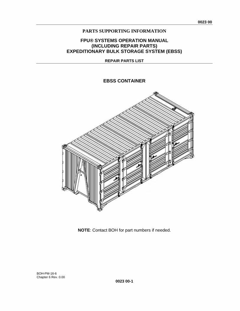
EBSS CONTAINER
NOTE: Contact BOH for part numbers if needed.

0023 00
BOH-PM-16-6 Chapter 6 Rev. 0.00
0023 00-2
EBSS CONTAINER
FIGURE 1 EBSS CONTAINER
1

0023 00
BOH-PM-16-6 Chapter 6 Rev. 0.00
0023 00-3
(1) ITEM NO.
(2) NSN
(3) CAGE
C
(4) PART
NUMBER
(5) DESCRIPTION AND USABLE ON CODE
(UOC)
(6) QTY
GROUP 01 FIGURE 1 EBSS CONTAINER
1 8145-01-695-4547 1NSG3 15002005-001 .EBSS CONTAINER GREEN UOC: FAA
1
1 8145-01-695-4674 1NSG3 15002005-002 .EBSS CONTAINER
TAN UOC: FAB 1
END OF FIGURE 1

0023 00
BOH-PM-16-6 Chapter 6 Rev. 0.00
0023 00-4
EBSS DOOR ASSEMBLIES # 1 THROUGH #4 STREET SIDE
FIGURE 2 EBSS DOOR ASSEMBLIES #1 THROUGH #4 STREET SIDE
1
2
3
4

0023 00
BOH-PM-16-6 Chapter 6 Rev. 0.00
0023 00-5
(1) ITEM NO.
(2) NSN
(3) CAGEC
(4) PART
NUMBER
(5) DESCRIPTION AND USABLE ON CODE
(UOC)
(6) QTY
GROUP 0101 FIGURE 2 EBSS DOOR ASSEMBLIES #1 THRU #8 STREET SIDE
1 Not Assigned 1NSG3 Not Assigned .DOOR COMPLETE #1 GREEN UOC: FAA
1
1 Not Assigned 1NSG3 Not Assigned .DOOR COMPLETE #1
TAN UOC: FAB 1
2 Not Assigned 1NSG3 Not Assigned .DOOR COMPLETE #2
GREEN UOC: FAA 1
2 Not Assigned 1NSG3 Not Assigned .DOOR COMPLETE #2
TAN UOC: FAB 1
3 Not Assigned 1NSG3 Not Assigned .DOOR COMPLETE #3
GREEN UOC: FAA 1
3 Not Assigned 1NSG3 Not Assigned .DOOR COMPLETE #3
TAN UOC: FAB 1
4 Not Assigned 1NSG3 Not Assigned .DOOR COMPLETE #4
GREEN UOC: FAA 1
4 Not Assigned 1NSG3 Not Assigned .DOOR COMPLETE #4
TAN UOC: FAB 1
END OF FIGURE 2
0023 00
BOH-PM-16-6 Chapter 6 Rev. 0.00
0023 00-6
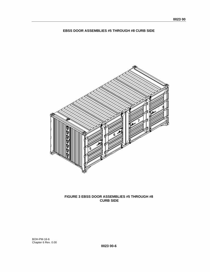
EBSS DOOR ASSEMBLIES #5 THROUGH #8 CURB SIDE
FIGURE 3 EBSS DOOR ASSEMBLIES #5 THROUGH #8 CURB SIDE
5
6
7
8

0023 00
BOH-PM-16-6 Chapter 6 Rev. 0.00
0023 00-7
(1) ITEM NO.
(2) NSN
(3) CAGEC
(4) PART
NUMBER
(5) DESCRIPTION AND USABLE ON CODE
(UOC)
(6) QTY
GROUP 0101 FIGURE 3 EBSS DOOR ASSEMBLIES #5 THRU #8 CURB SIDE
7 Not Assigned 1NSG3 Not Assigned .DOOR COMPLETE #5 GREEN UOC: FAA
1
7 Not Assigned 1NSG3 Not Assigned .DOOR COMPLETE #5 TAN UOC: FAB
1
8 Not Assigned 1NSG3 Not Assigned .DOOR COMPLETE #6 GREEN UOC: FAA
1
8 Not Assigned 1NSG3 Not Assigned .DOOR COMPLETE #6 TAN UOC: FAB
1
9 Not Assigned 1NSG3 Not Assigned .DOOR COMPLETE #7 GREEN UOC: FAA
1
9 Not Assigned 1NSG3 Not Assigned .DOOR COMPLETE #7 TAN UOC: FAB
1
10 Not Assigned 1NSG3 Not Assigned .DOOR COMPLETE #8 GREEN UOC: FAA
1
10 Not Assigned 1NSG3 Not Assigned .DOOR COMPLETE #8 TAN UOC: FAB
1
END OF FIGURE 3

0023 00
BOH-PM-16-6 Chapter 6 Rev. 0.00
0023 00-8
DOOR ASSEMBLIES #1 AND #5
FIGURE 4 DOOR ASSEMBLIES #1 AND #5
NOTE: HINGE KIT ONLY INCLUDES LEAF, PIN AND BEARINGS. DOES NOT INCLUDE HINGE BUTT WELDED TO CONTAINER.
2
5
4
3
1

0023 00
BOH-PM-16-6 Chapter 6 Rev. 0.00
0023 00-9
(1) ITEM NO.
(2) NSN
(3) CAGEC
(4) PART
NUMBER
(5) DESCRIPTION AND USABLE ON CODE
(UOC)
(6) QTY
GROUP 0101 FIGURE 4 EBSS DOOR ASSEMBLIES #1 AND #5
1 Not Assigned 1NSG3 Not Assigned .DOOR COMPLETE #1 GREEN UOC: FAA
1
2 Not Assigned 1NSG3 Not Assigned ..LEFTHAND LOCKROD ASSY W/ HDW GREEN
1
3 Not Assigned 1NSG3 Not Assigned ..SINGLE OVERLAP DOOR SEAL KIT
1
4 Not Assigned 1NSG3 Not Assigned ..HANDLE SEAL KIT GREEN
1
5 Not Assigned 1NSG3 Not Assigned ..HINGE KIT GREEN 4
1 Not Assigned 1NSG3 Not Assigned .DOOR COMPLETE #1 TAN UOC: FAB
1
2 Not Assigned 1NSG3 Not Assigned ..LEFTHAND LOCKROD ASSY W/ HDW TAN
1
3 Not Assigned 1NSG3 Not Assigned ..SINGLE OVERLAP DOOR SEAL KIT
1
4 Not Assigned 1NSG3 Not Assigned ..HANDLE SEAL KIT TAN
1
5 Not Assigned 1NSG3 Not Assigned ..HINGE KIT TAN 4
1 Not Assigned 1NSG3 Not Assigned .DOOR COMPLETE #5 GREEN UOC: FAA
1
2 Not Assigned 1NSG3 Not Assigned ..LEFTHAND LOCKROD ASSY W/ HDW GREEN
1
3 Not Assigned 1NSG3 Not Assigned ..SINGLE OVERLAP DOOR SEAL KIT
1
4 Not Assigned 1NSG3 Not Assigned ..HANDLE SEAL KIT GREEN
1
5 Not Assigned 1NSG3 Not Assigned ..HINGE KIT GREEN 4
1 Not Assigned 1NSG3 Not Assigned .DOOR COMPLETE #5 TAN UOC: FAB
1
2 Not Assigned 1NSG3 Not Assigned ..LEFTHAND LOCKROD ASSY W/ HDW TAN
1
3 Not Assigned 1NSG3 Not Assigned ..SINGLE OVERLAP DOOR SEAL KIT
1
4 Not Assigned 1NSG3 Not Assigned ..HANDLE SEAL KIT TAN
1
5 Not Assigned 1NSG3 Not Assigned ..HINGE KIT TAN 4
END OF FIGURE 4
NOTE: HINGE KIT ONLY INCLUDES LEAF, PIN AND BEARINGS. DOES NOT INCLUDE HINGE
BUTT WELDED TO CONTAINER

0023 00
BOH-PM-16-6 Chapter 6 Rev. 0.00
0023 00-10
DOOR ASSEMBLIES #2 AND #6
FIGURE 5 DOOR ASSEMBLIES #2 AND #6
2
3
4
1

0023 00
BOH-PM-16-6 Chapter 6 Rev. 0.00
0023 00-11
(1) ITEM NO.
(2) NSN
(3) CAGEC
(4) PART
NUMBER
(5) DESCRIPTION AND USABLE ON CODE
(UOC)
(6) QTY
GROUP 0101 FIGURE 5 EBSS DOOR ASSEMBLIES #2 AND #6
1 Not Assigned 1NSG3 Not Assigned .DOOR COMPLETE #2 GREEN UOC: FAA
1
2 Not Assigned 1NSG3 Not Assigned ..LEFTHAND LOCKROD ASSY W/ HDW GREEN
1
3 Not Assigned 1NSG3 Not Assigned ..DOUBLE OVERLAP DOOR SEAL KIT
1
4 Not Assigned 1NSG3 Not Assigned ..HANDLE SEAL KIT GREEN
1
1 Not Assigned 1NSG3 Not Assigned .DOOR COMPLETE #2 TAN UOC: FAB
1
2 Not Assigned 1NSG3 Not Assigned ..LEFTHAND LOCKROD ASSY W/ HDW TAN
1
3 Not Assigned 1NSG3 Not Assigned ..DOUBLE OVERLAP DOOR SEAL KIT
1
4 Not Assigned 1NSG3 Not Assigned ..HANDLE SEAL KIT TAN
1
1 Not Assigned 1NSG3 Not Assigned .DOOR COMPLETE #6 GREEN UOC: FAA
1
2 Not Assigned 1NSG3 Not Assigned ..LEFTHAND LOCKROD ASSY W/ HDW GREEN
1
3 Not Assigned 1NSG3 Not Assigned ..DOUBLE OVERLAP DOOR SEAL KIT
1
4 Not Assigned 1NSG3 Not Assigned ..HANDLE SEAL KIT GREEN
1
1 Not Assigned 1NSG3 Not Assigned .DOOR COMPLETE #6 TAN UOC: FAB
1
2 Not Assigned 1NSG3 Not Assigned ..LEFTHAND LOCKROD ASSY W/ HDW TAN
1
3 Not Assigned 1NSG3 Not Assigned ..DOUBLE OVERLAP DOOR SEAL KIT
1
4 Not Assigned 1NSG3 Not Assigned ..HANDLE SEAL KIT TAN
1
END OF FIGURE 5
0023 00
BOH-PM-16-6 Chapter 6 Rev. 0.00
0023 00-12
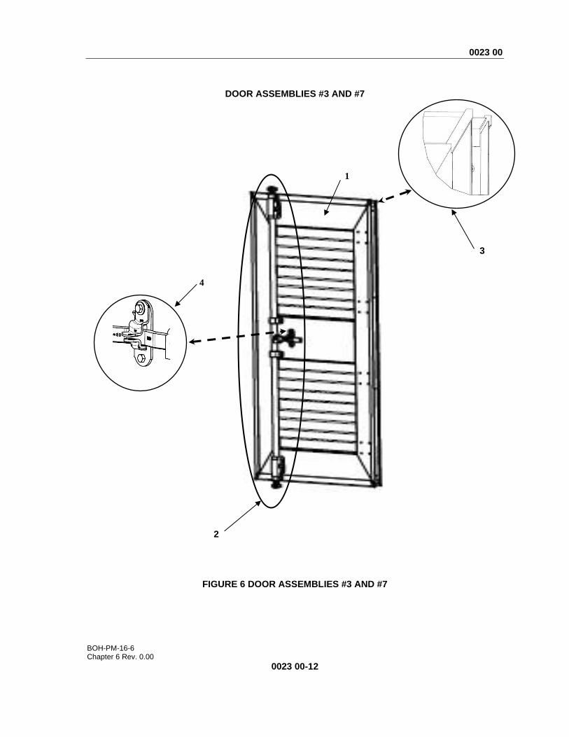
DOOR ASSEMBLIES #3 AND #7
FIGURE 6 DOOR ASSEMBLIES #3 AND #7
2
3
4
1

0023 00
BOH-PM-16-6 Chapter 6 Rev. 0.00
0023 00-13
(1) ITEM NO.
(2) NSN
(3) CAGEC
(4) PART
NUMBER
(5) DESCRIPTION AND USABLE ON CODE
(UOC)
(6) QTY
GROUP 0101 FIGURE 6 EBSS DOOR ASSEMBLIES #3 AND #7
1 Not Assigned 1NSG3 Not Assigned .DOOR COMPLETE #3 GREEN UOC: FAA
1
2 Not Assigned 1NSG3 Not Assigned ..RIGHTHAND LOCKROD ASSY W/ HDW GREEN
1
3 Not Assigned 1NSG3 Not Assigned ..SINGLE OVERLAP DOOR SEAL KIT
1
4 Not Assigned 1NSG3 Not Assigned ..HANDLE SEAL KIT GREEN
1
1 Not Assigned 1NSG3 Not Assigned .DOOR COMPLETE #3 TAN UOC: FAB
1
2 Not Assigned 1NSG3 Not Assigned ..RIGHTHAND LOCKROD ASSY W/ HDW TAN
1
3 Not Assigned 1NSG3 Not Assigned ..SINGLE OVERLAP DOOR SEAL KIT
1
4 Not Assigned 1NSG3 Not Assigned ..HANDLE SEAL KIT TAN
1
1 Not Assigned 1NSG3 Not Assigned .DOOR COMPLETE #7 GREEN UOC: FAA
1
2 Not Assigned 1NSG3 Not Assigned ..RIGHTHAND LOCKROD ASSY W/ HDW GREEN
1
3 Not Assigned 1NSG3 Not Assigned ..SINGLE OVERLAP DOOR SEAL KIT
1
4 Not Assigned 1NSG3 Not Assigned ..HANDLE SEAL KIT GREEN
1
1 Not Assigned 1NSG3 Not Assigned .DOOR COMPLETE #7 TAN UOC: FAB
1
2 Not Assigned 1NSG3 Not Assigned ..RIGHTHAND LOCKROD ASSY W/ HDW TAN
1
3 Not Assigned 1NSG3 Not Assigned ..SINGLE OVERLAP DOOR SEAL KIT
1
4 Not Assigned 1NSG3 Not Assigned ..HANDLE SEAL KIT TAN
1
END OF FIGURE 6

0023 00
BOH-PM-16-6 Chapter 6 Rev. 0.00
0023 00-14
DOOR ASSEMBLY #4
FIGURE 7 DOOR ASSEMBLY #4
NOTE: HINGE KIT ONLY INCLUDES LEAF, PIN AND BEARINGS. DOES NOT INCLUDE HINGE
BUTT WELDED TO CONTAINER.
2
3
4
5
1

0023 00
BOH-PM-16-6 Chapter 6 Rev. 0.00
0023 00-15
(1) ITEM NO.
(2) NSN
(3) CAGEC
(4) PART
NUMBER
(5) DESCRIPTION AND USABLE ON CODE
(UOC)
(6) QTY
GROUP 0101 FIGURE 7 EBSS DOOR ASSEMBLY #4
1 Not Assigned 1NSG3 Not Assigned .DOOR COMPLETE #4 GREEN UOC: FAA
1
2 Not Assigned 1NSG3 Not Assigned ..RIGHTHAND LOCKROD ASSY W/ HDW GREEN
1
3 Not Assigned 1NSG3 Not Assigned ..SINGLE OVERLAP DOOR SEAL KIT
1
4 Not Assigned 1NSG3 Not Assigned ..HANDLE SEAL KIT GREEN
1
5 Not Assigned 1NSG3 Not Assigned ..HINGE KIT GREEN 4
1 Not Assigned 1NSG3 Not Assigned .DOOR COMPLETE #4 TAN UOC: FAB
1
2 Not Assigned 1NSG3 Not Assigned ..RIGHTHAND LOCKROD ASSY W/ HDW TAN
1
3 Not Assigned 1NSG3 Not Assigned ..SINGLE OVERLAP DOOR SEAL KIT
1
4 Not Assigned 1NSG3 Not Assigned ..HANDLE SEAL KIT TAN
1
5 Not Assigned 1NSG3 Not Assigned ..HINGE KIT TAN 4
END OF FIGURE 7
0023 00
BOH-PM-16-6 Chapter 6 Rev. 0.00
0023 00-16
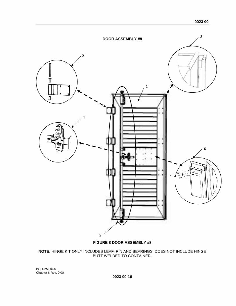
DOOR ASSEMBLY #8
FIGURE 8 DOOR ASSEMBLY #8
NOTE: HINGE KIT ONLY INCLUDES LEAF, PIN AND BEARINGS. DOES NOT INCLUDE HINGE BUTT WELDED TO CONTAINER.
2
3
4
5
1
6
0023 00
BOH-PM-16-6 Chapter 6 Rev. 0.00
0023 00-17
(1) ITEM NO.
(2) NSN
(3) CAGEC
(4) PART
NUMBER
(5) DESCRIPTION AND USABLE ON CODE
(UOC)
(6) QTY
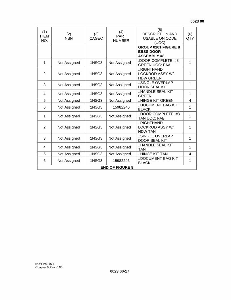
GROUP 0101 FIGURE 8 EBSS DOOR ASSEMBLY #8
1 Not Assigned 1NSG3 Not Assigned .DOOR COMPLETE #8 GREEN UOC: FAA
1
2 Not Assigned 1NSG3 Not Assigned ..RIGHTHAND LOCKROD ASSY W/ HDW GREEN
1
3 Not Assigned 1NSG3 Not Assigned ..SINGLE OVERLAP DOOR SEAL KIT
1
4 Not Assigned 1NSG3 Not Assigned ..HANDLE SEAL KIT GREEN
1
5 Not Assigned 1NSG3 Not Assigned ..HINGE KIT GREEN 4
6 Not Assigned 1NSG3 15982246 ..DOCUMENT BAG KIT BLACK
1
1 Not Assigned 1NSG3 Not Assigned ..DOOR COMPLETE #8 TAN UOC: FAB
1
2 Not Assigned 1NSG3 Not Assigned ..RIGHTHAND LOCKROD ASSY W/ HDW TAN
1
3 Not Assigned 1NSG3 Not Assigned ..SINGLE OVERLAP DOOR SEAL KIT
1
4 Not Assigned 1NSG3 Not Assigned ..HANDLE SEAL KIT TAN
1
5 Not Assigned 1NSG3 Not Assigned ..HINGE KIT TAN 4
6 Not Assigned 1NSG3 15982246 ..DOCUMENT BAG KIT BLACK
1
END OF FIGURE 8

0023 00
BOH-PM-16-6 Chapter 6 Rev. 0.00
0023 00-18
EBSS DOOR STRAPS
FIGURE 9 EBSS DOOR STRAPS
1
2

0023 00
BOH-PM-16-6 Chapter 6 Rev. 0.00
0023 00-19
(1) ITEM NO.
(2) NSN
(3) CAGE
C
(4) PART
NUMBER
(5) DESCRIPTION AND USABLE ON CODE
(UOC)
(6) QTY
GROUP 0101 FIGURE 9 EBSS DOOR STRAPS
1 Not Assigned 1NSG3 16230211 .STRAPS ASSEMBLY 62” 4
2 Not Assigned 1NSG3 15940110-001 .D-RING KIT GREEN 1
2 Not Assigned 1NSG3 15940110-002 .D-RING KIT TAN 1
3 Not Assigned 1NSG3 NA ..D-RING #700-ZN 1
4 Not Assigned 1NSG3 NA ..RIVET #SB68 2
NA Not Assigned 1NSG3 NA ..SEALANT SIKA-FLEX
221 1
END OF FIGURE 9
0023 00
BOH-PM-16-6 Chapter 6 Rev. 0.00
0023 00-20
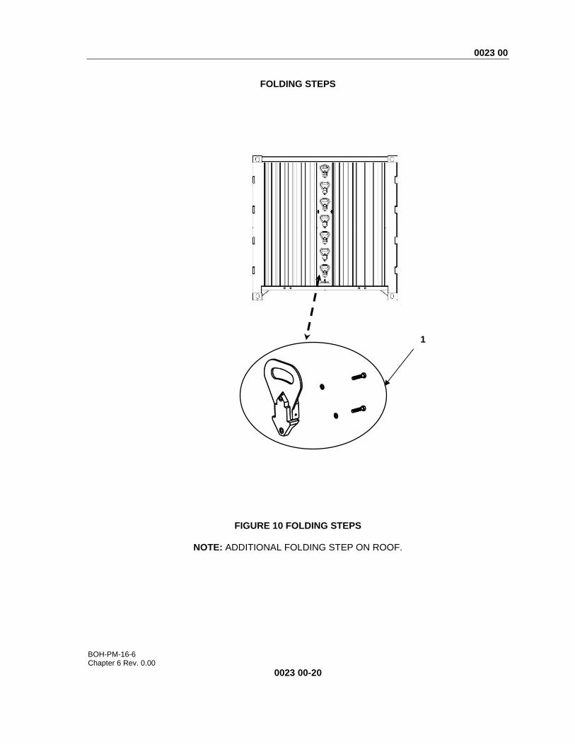
FOLDING STEPS
FIGURE 10 FOLDING STEPS
NOTE: ADDITIONAL FOLDING STEP ON ROOF.
1

0023 00
BOH-PM-16-6 Chapter 6 Rev. 0.00
0023 00-21
(1) ITEM NO.
(2) NSN
(3) CAGE
C
(4) PART
NUMBER
(5) DESCRIPTION AND USABLE ON CODE
(UOC)
(6) QTY
GROUP 0102 FIGURE 10 FOLDING STEPS
1 Not Assigned 1NSG3 15988603-001 .FOOT STEP W/ MOUNTING HARDWARE GREEN
8
1 Not Assigned 1NSG3 15988603-002 .FOOT STEP W/ MOUNTING HARDWARE TAN
8
END OF FIGURE 10

0023 00
BOH-PM-16-6 Chapter 6 Rev. 0.00
0023 00-22
REAR ROLLER ASSEMBLY
FIGURE 11 REAR ROLLER ASSEMBLY
4
5 6
2
1
3
5
9
8
7
4
0023 00
BOH-PM-16-6 Chapter 6 Rev. 0.00
0023 00-23
(1) ITEM NO.
(2) NSN
(3) CAGEC
(4) PART
NUMBER
(5) DESCRIPTION AND USABLE ON CODE
(UOC)
(6) QTY
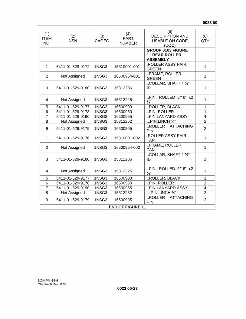
GROUP 0103 FIGURE 11 REAR ROLLER ASSEMBLY
1 5411-01-529-9172 1NSG3 15310001-001 .ROLLER ASSY PAIR. GREEN
1
2 Not Assigned 1NSG3 16500954-001 ..FRAME, ROLLER GREEN
1
3 5411-01-529-9180 1NSG3 15312286 ..COLLAR, SHAFT 1 ½” ID
1
4 Not Assigned 1NSG3 15312225 ..PIN, ROLLED 5/16” x2 ¼”
1
5 5411-01-529-9177 1NSG3 16500903 ..ROLLER, BLACK 1
6 5411-01-529-9178 1NSG3 16500950 ..PIN, ROLLER 1
7 5411-01-529-9190 1NSG3 16500955 ..PIN LANYARD ASSY 4
8 Not Assigned 1NSG3 15312262 ...PIN,LINCH ¼” 2
9 5411-01-529-9179 1NSG3 16500905 ..ROLLER ATTACHING PIN
2
1 5411-01-529-9176 1NSG3 15310001-002 .ROLLER ASSY PAIR. TAN
1
2 Not Assigned 1NSG3 16500954-002 ..FRAME, ROLLER TAN
1
3 5411-01-529-9180 1NSG3 15312286 ..COLLAR, SHAFT 1 ½” ID
1
4 Not Assigned 1NSG3 15312225 ..PIN, ROLLED 5/16” x2 ¼”
1
5 5411-01-529-9177 1NSG3 16500903 ..ROLLER, BLACK 1
6 5411-01-529-9178 1NSG3 16500950 ..PIN, ROLLER 1
7 5411-01-529-9190 1NSG3 16500955 ..PIN LANYARD ASSY 4
8 Not Assigned 1NSG3 15312262 …PIN,LINCH ¼” 2
9 5411-01-529-9179 1NSG3 16500905 ..ROLLER ATTACHING PIN
2
END OF FIGURE 11

0023 00
BOH-PM-16-6 Chapter 6 Rev. 0.00
0023 00-24
WALL VENT KIT
FIGURE 12 WALL VENT KIT
1
2
3

0023 00
BOH-PM-16-6 Chapter 6 Rev. 0.00
0023 00-25
(1) ITEM NO.
(2) NSN
(3) CAGEC
(4) PART NUMBER
(5) DESCRIPTION AND
USABLE ON CODE (UOC)
(6) QTY
GROUP 0104 FIGURE 12 WALL VENT KIT
1 Not Assigned 1NSG3 15940111-001 .WALL VENT KIT GREEN 2
1 Not Assigned 1NSG3 15940111-002 .WALL VENT KIT TAN 2
2 Not Assigned 1NSG3 NA ..VENT COVER 1
3 Not Assigned 1NSG3 NA ..RIVET 3/16X3/8” SB66CLD 4
NA Not Assigned 1NSG3 NA ..SEALANT, SIKA-FLEX 221 1
END OF FIGURE 12
0023 00
BOH-PM-16-6 Chapter 6 Rev. 0.00
0023 00-26
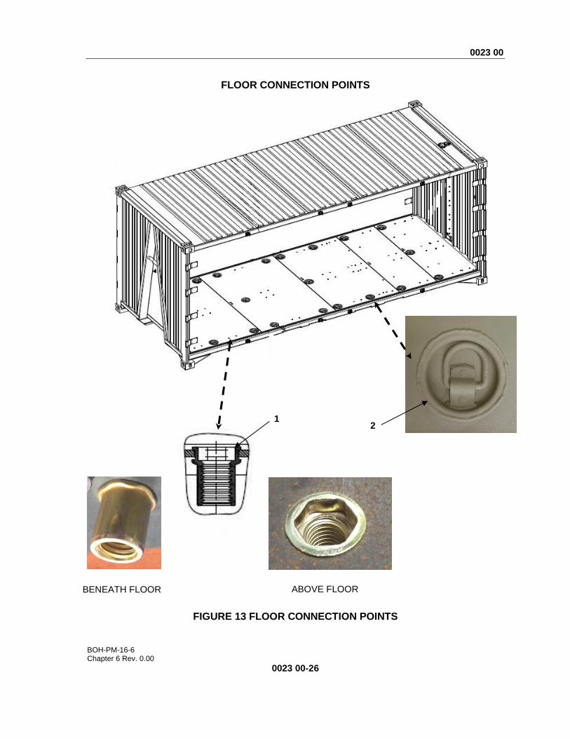
FLOOR CONNECTION POINTS
FIGURE 13 FLOOR CONNECTION POINTS
BENEATH FLOOR ABOVE FLOOR
1 2

0023 00
BOH-PM-16-6 Chapter 6 Rev. 0.00
0023 00-27
(1)
ITEM NO.
(2) NSN
(3) CAGEC
(4) PART NUMBER
(5) DESCRIPTION AND
USABLE ON CODE (UOC)
(6) QTY
GROUP 0105 FIGURE 13 FLOOR CONNECTION POINTS
1 Not Assigned 1NSG3 16280029 .RIV-NUT 80
2 Not Assigned 1NSG3 Not Assigned .RECESSED TIEDOWN RING
20
END OF FIGURE 13
END OF WORK PACKAGE

BOH-PM-16-6 Chapter 6 Rev. 0.00
This page was intentionally left blank
0024 00
BOH-PM-16-6 Chapter 6 Rev. 0.00
0024 00-1
PARTS SUPPORTING INFORMATION
FPU® SYSTEMS OPERATION MANUAL (INCLUDING REPAIR PARTS)
EXPEDITIONARY BULK STORAGE SYSTEM (EBSS)
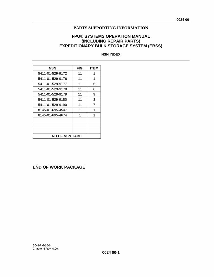
NSN INDEX
END OF WORK PACKAGE
NSN FIG. ITEM
5411-01-529-9172 11 1
5411-01-529-9176 11 1
5411-01-529-9177 11 5
5411-01-529-9178 11 6
5411-01-529-9179 11 9
5411-01-529-9180 11 3
5411-01-529-9190 11 7
8145-01-695-4547 1 1
8145-01-695-4674 1 1
END OF NSN TABLE

BOH-PM-16-6 Chapter 6 Rev. 0.00
This page was intentionally left blank
0025 00
BOH-PM-16-6 Chapter 6 Rev. 0.00
0025 00-1
PARTS SUPPORTING INFORMATION
FPU® SYSTEMS OPERATION MANUAL (INCLUDING REPAIR PARTS)
EXPEDITIONARY BULK STORAGE SYSTEM (EBSS)
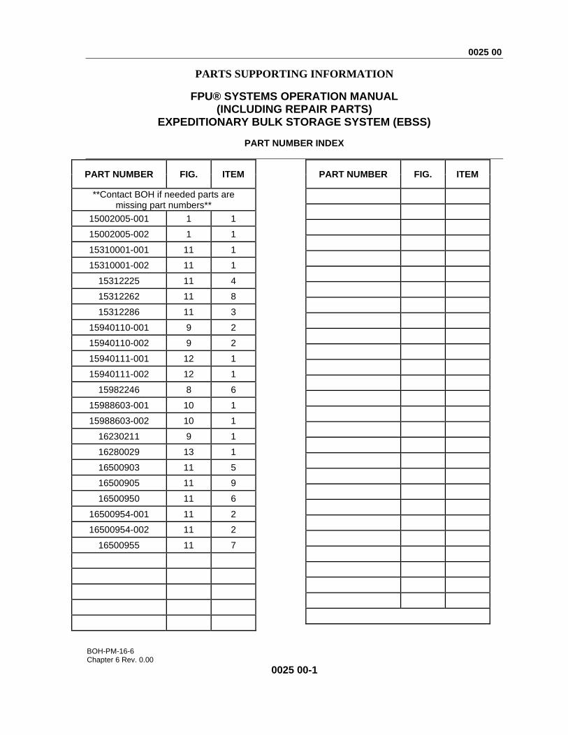
PART NUMBER INDEX
PART NUMBER FIG. ITEM
**Contact BOH if needed parts are missing part numbers**
15002005-001 1 1
15002005-002 1 1
15310001-001 11 1
15310001-002 11 1
15312225 11 4
15312262 11 8
15312286 11 3
15940110-001 9 2
15940110-002 9 2
15940111-001 12 1
15940111-002 12 1
15982246 8 6
15988603-001 10 1
15988603-002 10 1
16230211 9 1
16280029 13 1
16500903 11 5
16500905 11 9
16500950 11 6
16500954-001 11 2
16500954-002 11 2
16500955 11 7
PART NUMBER FIG. ITEM
0025 00
BOH-PM-16-6 Chapter 6 Rev. 0.00
0025 00-2
PART NUMBER FIG. ITEM
PART NUMBER FIG. ITEM
END OF WORK PACKAGE
BOH-PM-16-6 Chapter 6 Rev. 0.00

BOH-PM-16-6 Chapter 6 Rev. 0.00
This page was intentionally left blank

BOH-PM-16-6 Chapter 6 Rev. 0.00
THE METRIC SYSTEM AND EQUIVALENTS
Linear Measure Liquid Measure 1 centimeter = 10 millimeters = .39 inch 1 centiliter = 10 milliliters = .34 fl. ounce 1 decimeter = 10 centimeters = 3.94 inches
1 deciliter = 10 centiliters = 3.38 fl. ounces
1 meter = 10 decimeters = 39.37 inches
1 liter = 10 deciliters = 33.81 fl. ounces
1 decameter = 10 meters = 32.8 feet 1 deciliter = 10 liters = 2.64 gallons 1 hectometer = 10 decameters = 328.08 feet
1 hectoliter = 10 deciliters = 26.42 gallons
1 kilometer = 10 hectometers = 3,280.8 feet
1 kiloliter = 10 hectoliters = 264.18 gallons
Weights Square Measure 1 centigram = 10 milligrams = .15 grain 1 sq. centimeter = 100 sq. millimeters = .155 sq.
inch 1 decigram = 10 centigrams = 1.54 grains
1 sq. decimeter = 100 sq. centimeters = 15.5 sq. inches
1 gram = 10 decigrams = .035 ounce 1 sq. meter (centare) = 100 sq. decimeters = 10.76 sq. feet
1 dekagram = 10 grams = .35 ounce 1 sq. decameter (are) = 100 sq. meters = 1,076.4 sq. feet
1 hectogram = 10 dekagrams = 3.52 ounces
1 sq. hectometer (hectare) = 100 sq. decameters = 2.47 acres
1 kilogram = 10 hectograms = 2.2 pounds
1 sq. kilometer = 100 sq. hectometers = .386 sq. mile
1 quintal = 100 kilograms = 220.46 pounds
1 metric ton = 10 quintals = 1.1 short tons
Cubic Measure
1 cu. centimeter = 1000 cu. millimeters = .06 cu. inch
1 cu. decimeter = 1000 cu. centimeters = 61.02 cu. inches
1 cu. meter = 1000 cu. decimeters = 35.31 feet
BOH-PM-16-6 Chapter 6 Rev. 0.00
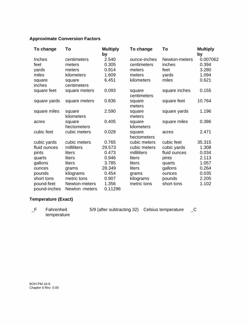
Approximate Conversion Factors
To change To Multiply by
To change To Multiply by
Inches centimeters 2.540 ounce-inches Newton-meters 0.007062 feet meters 0.305 centimeters inches 0.394 yards meters 0.914 meters feet 3.280 miles kilometers 1.609 meters yards 1.094 square inches
square centimeters
6.451 kilometers miles 0.621
square feet square meters 0.093 square centimeters
square inches 0.155
square yards square meters 0.836 square meters
square feet 10.764
square miles square kilometers
2.590 square meters
square yards 1.196
acres square hectometers
0.405 square kilometers
square miles 0.386
cubic feet cubic meters 0.028 square hectometers
acres 2.471
cubic yards cubic meters 0.765 cubic meters cubic feet 35.315 fluid ounces milliliters 29.573 cubic meters cubic yards 1.308 pints liters 0.473 milliliters fluid ounces 0.034 quarts liters 0.946 liters pints 2.113 gallons liters 3.785 liters quarts 1.057 ounces grams 28.349 liters gallons 0.264 pounds kilograms 0.454 grams ounces 0.035 short tons metric tons 0.907 kilograms pounds 2.205 pound-feet Newton-meters 1.356 metric tons short tons 1.102 pound-inches Newton -meters 0.11296
Temperature (Exact) _F Fahrenheit
temperature 5/9 (after subtracting 32) Celsius temperature _C