FPS-500 / FPS 750 - Solving Diesel Fuel Problems · FPS -500 / FPS 750 conditions and stabilizes...
12
FPS-500 / FPS 750 Fuel Polishing System Eliminates Microbial Contamination Installation and Operating Manual • Stabilizes Fuel • Removes Water & Sludge • Prevents Tank Sediments • Improves Engine Reliability • Optimizes Fuel Quality Optimal Fuel Quality Provides Peak Engine Performance More Power • Less Smoke • Saves Fuel
Transcript of FPS-500 / FPS 750 - Solving Diesel Fuel Problems · FPS -500 / FPS 750 conditions and stabilizes...
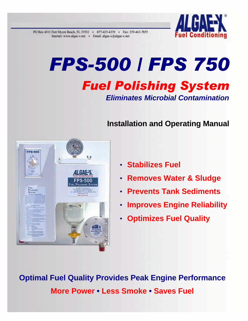
FPS-500 / FPS 750 Fuel Polishing System
Eliminates Microbial Contamination
Installation and Operating Manual
• Stabilizes Fuel
• Removes Water & Sludge
• Prevents Tank Sediments
• Improves Engine Reliability
• Optimizes Fuel Quality
Optimal Fuel Quality Provides Peak Engine Performance
More Power • Less Smoke • Saves Fuel
FPS-500 / FPS-750 ALGAE-X 2003-Rev. A 2
INSTALLATION AND OPERATING MANUAL
CONTENT FPS-500 OVERVIEW – BASIC SYSTEM COMPONENTS........................................................ 4 FPS-750 OVERVIEW – BASIC SYSTEM COMPONENTS........................................................ 5 GENERAL SPECIFICATIONS ................................................................................................... 6
FPS-500 ................................................................................................................................. 6 FPS-750 ................................................................................................................................. 6
PRIMARY INSPECTION............................................................................................................ 6 INSTALLATION ......................................................................................................................... 7
Mounting................................................................................................................................. 7 Electrical................................................................................................................................. 7 Plumbing ................................................................................................................................ 8
IMPORTANT INSTALLATION PRECAUTIONS......................................................................... 8 OPERATION.............................................................................................................................. 9
Stabilizing and Optimizing Fuel Quality.................................................................................. 9 TROUBLESHOOTING ............................................................................................................. 10 FUEL POLISHING SYSTEMS WARRANTY............................................................................ 11 TECHNICAL ASSISTANCE AND ORDERING ........................................................................ 12
Replacement filter elements................................................................................................. 12 FPS-500 / FPS-750 SYSTEM IDENTIFICATION..................................................................... 12
FPS-500 / FPS-750 ALGAE-X 2003-Rev. A 3
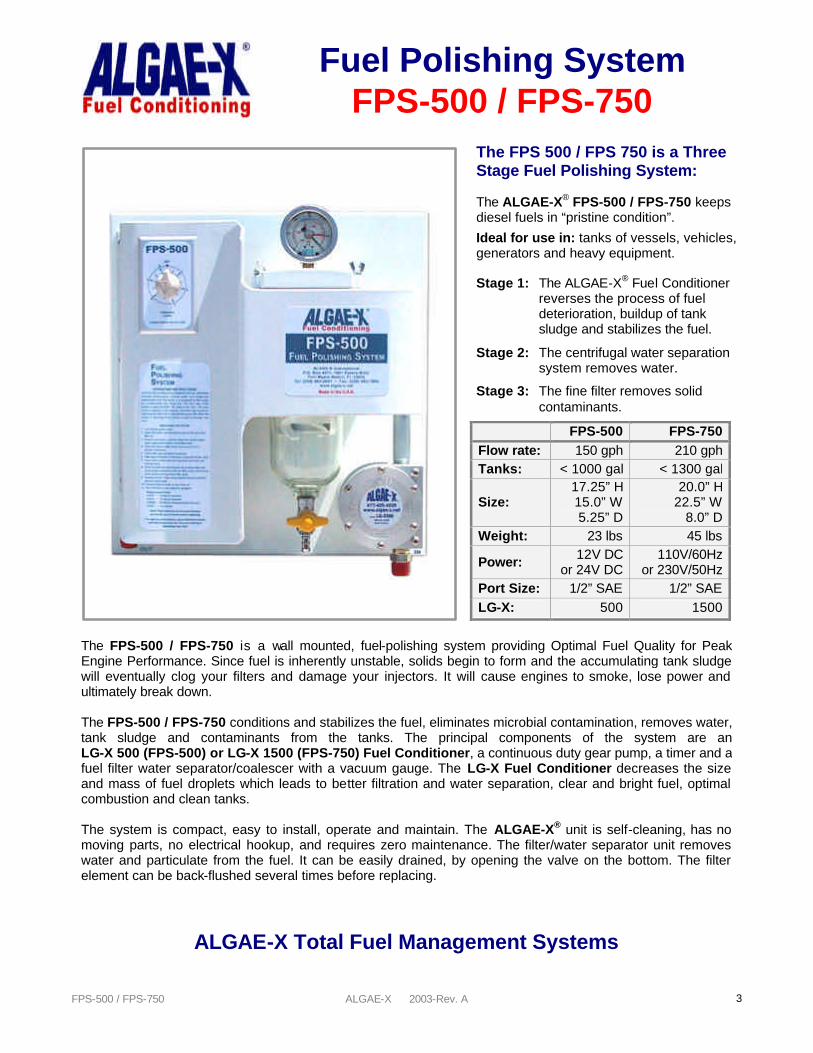
The FPS-500 / FPS-750 is a wall mounted, fuel-polishing system providing Optimal Fuel Quality for Peak Engine Performance. Since fuel is inherently unstable, solids begin to form and the accumulating tank sludge will eventually clog your filters and damage your injectors. It will cause engines to smoke, lose power and ultimately break down. The FPS-500 / FPS-750 conditions and stabilizes the fuel, eliminates microbial contamination, removes water, tank sludge and contaminants from the tanks. The principal components of the system are an LG-X 500 (FPS-500) or LG-X 1500 (FPS-750) Fuel Conditioner, a continuous duty gear pump, a timer and a fuel filter water separator/coalescer with a vacuum gauge. The LG-X Fuel Conditioner decreases the size and mass of fuel droplets which leads to better filtration and water separation, clear and bright fuel, optimal combustion and clean tanks. The system is compact, easy to install, operate and maintain. The ALGAE-X® unit is self-cleaning, has no moving parts, no electrical hookup, and requires zero maintenance. The filter/water separator unit removes water and particulate from the fuel. It can be easily drained, by opening the valve on the bottom. The filter element can be back-flushed several times before replacing.
ALGAE-X Total Fuel Management Systems
Fuel Polishing System FPS-500 / FPS-750
The FPS 500 / FPS 750 is a Three Stage Fuel Polishing System: The ALGAE-X® FPS-500 / FPS-750 keeps diesel fuels in “pristine condition”.
Ideal for use in: tanks of vessels, vehicles, generators and heavy equipment. Stage 1: The ALGAE-X® Fuel Conditioner
reverses the process of fuel deterioration, buildup of tank sludge and stabilizes the fuel.
Stage 2: The centrifugal water separation system removes water.
Stage 3: The fine filter removes solid contaminants.
FPS-500 FPS-750 Flow rate: 150 gph 210 gph Tanks: < 1000 gal < 1300 gal
Size: 17.25” H 15.0” W 5.25” D
20.0” H 22.5” W
8.0” D Weight: 23 lbs 45 lbs
Power: 12V DC or 24V DC
110V/60Hz or 230V/50Hz
Port Size: 1/2” SAE 1/2” SAE LG-X: 500 1500
FPS-500 / FPS-750 ALGAE-X 2003-Rev. A 4
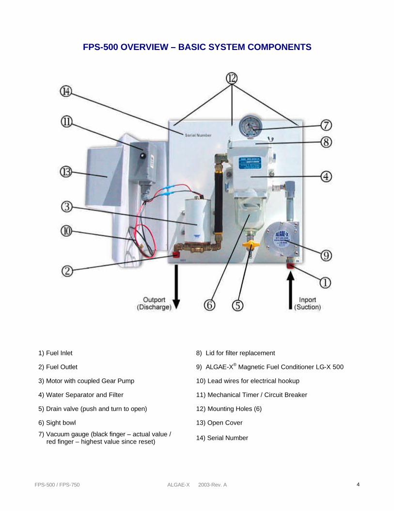
FPS-500 OVERVIEW – BASIC SYSTEM COMPONENTS
1) Fuel Inlet 8) Lid for filter replacement
2) Fuel Outlet 9) ALGAE-X® Magnetic Fuel Conditioner LG-X 500
3) Motor with coupled Gear Pump 10) Lead wires for electrical hookup
4) Water Separator and Filter 11) Mechanical Timer / Circuit Breaker
5) Drain valve (push and turn to open) 12) Mounting Holes (6)
6) Sight bowl 13) Open Cover
7) Vacuum gauge (black finger – actual value / red finger – highest value since reset) 14) Serial Number
FPS-500 / FPS-750 ALGAE-X 2003-Rev. A 5
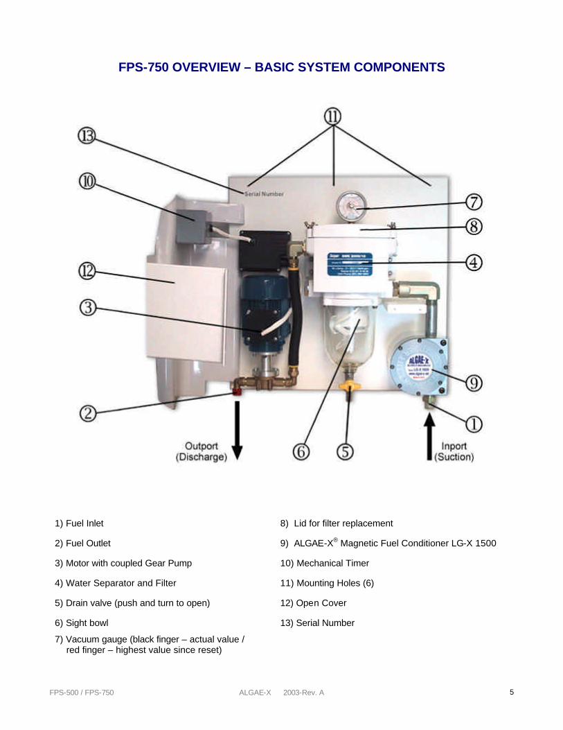
FPS-750 OVERVIEW – BASIC SYSTEM COMPONENTS
1) Fuel Inlet 8) Lid for filter replacement
2) Fuel Outlet 9) ALGAE-X® Magnetic Fuel Conditioner LG-X 1500
3) Motor with coupled Gear Pump 10) Mechanical Timer
4) Water Separator and Filter 11) Mounting Holes (6)
5) Drain valve (push and turn to open) 12) Open Cover
6) Sight bowl 13) Serial Number
7) Vacuum gauge (black finger – actual value / red finger – highest value since reset)
FPS-500 / FPS-750 ALGAE-X 2003-Rev. A 6
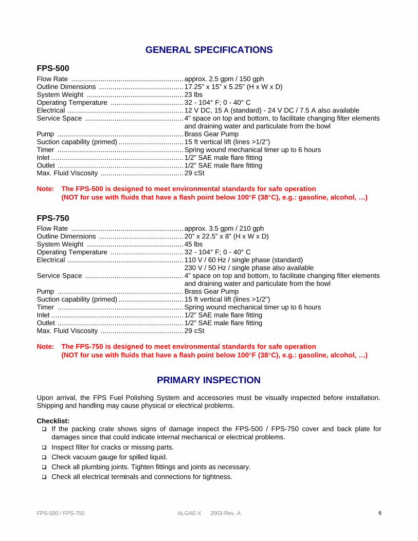
GENERAL SPECIFICATIONS
FPS-500 Flow Rate ......................................................... approx. 2.5 gpm / 150 gph Outline Dimensions ........................................... 17.25” x 15” x 5.25” (H x W x D) System Weight ................................................. 23 lbs Operating Temperature ..................................... 32 - 104° F; 0 - 40° C Electrical ........................................................... 12 V DC, 15 A (standard) - 24 V DC / 7.5 A also available Service Space .................................................. 4” space on top and bottom, to facilitate changing filter elements and draining water and particulate from the bowl Pump ................................................................ Brass Gear Pump Suction capability (primed) ................................. 15 ft vertical lift (lines >1/2”) Timer ................................................................ Spring wound mechanical timer up to 6 hours Inlet ................................................................... 1/2” SAE male flare fitting Outlet ................................................................ 1/2” SAE male flare fitting Max. Fluid Viscosity .......................................... 29 cSt Note: The FPS-500 is designed to meet environmental standards for safe operation
(NOT for use with fluids that have a flash point below 100°F (38°C), e.g.: gasoline, alcohol, …)
FPS-750 Flow Rate ......................................................... approx. 3.5 gpm / 210 gph Outline Dimensions ........................................... 20” x 22.5” x 8” (H x W x D) System Weight ................................................. 45 lbs Operating Temperature ..................................... 32 - 104° F; 0 - 40° C Electrical ........................................................... 110 V / 60 Hz / single phase (standard) .......................................................................... 230 V / 50 Hz / single phase also available Service Space .................................................. 4” space on top and bottom, to facilitate changing filter elements and draining water and particulate from the bowl Pump ................................................................ Brass Gear Pump Suction capability (primed) ................................. 15 ft vertical lift (lines >1/2”) Timer ................................................................ Spring wound mechanical timer up to 6 hours Inlet ................................................................... 1/2” SAE male flare fitting Outlet ................................................................ 1/2” SAE male flare fitting Max. Fluid Viscosity .......................................... 29 cSt Note: The FPS-750 is designed to meet environmental standards for safe operation
(NOT for use with fluids that have a flash point below 100°F (38°C), e.g.: gasoline, alcohol, …)
PRIMARY INSPECTION
Upon arrival, the FPS Fuel Polishing System and accessories must be visually inspected before installation. Shipping and handling may cause physical or electrical problems. Checklist: q If the packing crate shows signs of damage inspect the FPS-500 / FPS-750 cover and back plate for
damages since that could indicate internal mechanical or electrical problems. q Inspect filter for cracks or missing parts. q Check vacuum gauge for spilled liquid. q Check all plumbing joints. Tighten fittings and joints as necessary. q Check all electrical terminals and connections for tightness.
FPS-500 / FPS-750 ALGAE-X 2003-Rev. A 7
INSTALLATION
! IMPORTANT ! It is recommended that only qualified, experienced personnel, familiar with this type of equipment, who have read and understood all the instructions in this manual should install, operate and maintain the system.
MOUNTING The FPS-500 / FPS-750 should be wall mounted on a hard, level surface. This unit is designed for well-ventilated indoor use and should be located as close to the tank as possible. Allow about 4” of space on top of the unit to change the filter element comfortably and sufficient space on the bottom to drain the system. This space is also necessary to ensure sufficient ventilation of cooling air for the motor.
ELECTRICAL
! WARNING ! To avoid the risk of electric shock make sure that the power supply to the system is disconnected and ensure that the system is at zero volts, before working on any of the system’s electrical parts.
Make sure that the motor has the same rated voltage as your electrical system. FPS-500 systems are available in 12V DC, 24V DC and FPS-750 systems in 110V AC and 230V AC. FPS-500 The systems with either 12 V DC or 24 V DC motor connect to the positive lead from your battery with the red wire of the motor and to the negative lead with the black wire. After the initial wiring of the motor check system operation to insure that it is running in the correct direction. If the motor is running in the wrong direction or is not running at all, reverse the two electrical leads. FPS-750 The FPS-750 may only be connected to properly grounded power sources for operator safety. Do not run over, crush or pull the power supply cable or extension lead otherwise it may be damaged. Protect the cable from oil, heat and sharp edges.
! WARNING ! The system must be properly grounded for operator safety.
Depending on length of run, use #12 AWG or larger copper wiring and connect system to a separate 20A breaker (not included in shipment).
`
`
`

FPS-500 / FPS-750 ALGAE-X 2003-Rev. A 8
PLUMBING Use proper quality approved fuel line materials with at least 1/2” inner diameter. Smaller plumbing will place excessive load on the motor and shorten its life. A valve should be installed on the inlet and outlet port of the FPS system. The pick-up tube/line(s) (suction) should originate from the lowest point of the tank and should be connected directly to the systems ALGAE-X® Magnetic Fuel Conditioner (“IN” port). For optimal performance, insure that the inlet (suction) line(s) are free and nothing is restricting their flow. Note: It is recommended to install a foot valve to keep the system primed, especially if the system is
located above the lowest possible fuel level in the tank. If the FPS Fuel Polishing System is mounted below tank top level, a priming tee should be installed on the highest point of the suction line to be able to easily prime the systems delivery line. The return line(s) (discharge) should be plumbed to the outlet of the pump (“OUT” port) and enter the tank as far as possible from the pick up tube of the FPS system close to the tank bottom. For optimal performance, insure that the outlet (discharge or return) line(s) are free and nothing is restricting their flow. The system capabilities are 15 ft suction (vertical) lift, when connected to piping of 1/2” ID or more with no additional flow restrictions such as valves, 90-degree connectors or other plumbing accessories. For continuous optimal performance, make sure suction and discharge lines are free and that nothing is blocking the flow of fuel.
! WARNING ! The gear pump is capable of developing extremely high pressure. Care must be taken not to operate the pump with either the suction (inlet) or discharge (outlet) lines closed. Serious damage may occur.
! WARNING ! If the pump is allowed to run without fuel, pump damage will occur.
IMPORTANT INSTALLATION PRECAUTIONS
The suction line of the FPS system should be independent and separate from the suction line of the engine. If that is not possible, appropriate valves must be installed to completely separate the FPS from the engine fuel system to prevent any possible interference with safe engine operation. The discharge should also be independent and separate of the engine’s fuel return line back to the tank. If the return line from the engine and the discharge of the FPS Fuel Polishing System have to be combined in any way, adequate valves should be installed to prevent any possible interference with safe engine operation. (Many engines are already equipped with a check valve – check with engine manufacturer). Note: If any of the FPS system’s fuel lines are used in combination with the engine’s fuel system, the
FPS Fuel Polishing System should be disabled during engine operation.
`
`
FPS-500 / FPS-750 ALGAE-X 2003-Rev. A 9
OPERATION
! WARNING ! Do not fill with gasoline. This System is not meant for use with gasoline nor with other flammable liquids having a flash point less than 100°F. Use with gasoline or use with any flammable liquids at a temperature exceeding their flash point, presents an immediate explosion and fire hazard. ! WARNING ! Do not use the FPS at a temperature exceeding the flash point of its contents. ! WARNING ! Only run the system when you are able to supervise it. Operating the FPS-750 / FPS-500 on an unattended vehicle or vessel is NOT recommended.
It is necessary to prime the filter before initial use. Remove the top filter cover by removing the four wing nuts. Fill the bowl and filter body, as well as the suction line with diesel fuel and replace the cover. The timer can now be set to the desired run time. The pump will automatically shut off after this pre-set time. Set the tell-tale gauge pressure indicator (red pointer) to slightly above the black needle prior to operation. The gauge will indicate maximum vacuum pressure during system operation. When the indicator reaches 15“ HG, it is time to back-flush or change the element. The same procedure is necessary if the water level reaches 30% of the clear bowl. Servicing and Back-flushing the FPS filter:
1. Turn off the FPS-500 / FPS-750 pump motor 2. Open the brass colored bleed screw on the top of the filter cover 3. Place a fuel waste container below the yellow safety drain valve at the bottom of the filter bowl 4. Open the yellow safety drain valve (push & turn counter clockwise) 5. Close after approximately 2 seconds 6. After approximately 10 seconds reopen the drain valve 7. Close after visible sediment, particles and water are drained from the bowl 8. Prime the filter by removing the cover (4 wing bolts) and pouring clean diesel fuel into the filter body until the
fuel level reaches the top of the filter body 9. Replace the lid. Note: evenly tighten the wing bolts to ensure a good seal 10. Close bleed screw on top of the lid 11. The FPS-500 / FPS-750 is ready for operation
Note: Elements can be back-flushed up to 5 times before replacement is required Note: Disposal of fuel should be done in accordance with Federal, State and Local regulations.
! WARNING ! Some fuels may have been treated with biocides. Biocides are extremely toxic and may enter the body through the skin. It is recommended to use adequate protection and avoid skin contact with biocide-treated fuels.
STABILIZING AND OPTIMIZING FUEL QUALITY We recommend treating the fuel with the ALGAE-X® Fuel Catalyst (AFC-705). This will enhance and accelerate the tank cleaning process by breaking down and dissolving existing tank sludge. AFC-705 will decontaminate compartments of the tank that are out of reach of the suction line. Depending on the condition of the fuel and the amount of sludge build-up, it is recommended to initially use a double dose of one to twenty-five hundred (1:2500) instead of one to five thousand (1:5000) This has proven to be very helpful in accelerating the tank cleaning process. AFC-705 contains detergent, surfactant, dispersant, corrosion inhibitor, lubricity enhancer and combustion catalyst. It does not contain biocides. AFC-705 should always be used periodically in particular to stabilize fuel that is stored for longer periods of time. Note: In cases of severe tank contaminant build-up and high water level in bottom, it is recommended to
polish the fuel before initial use of an FPS system.
`
`
`
`
FPS-500 / FPS-750 ALGAE-X 2003-Rev. A 10
TROUBLESHOOTING
No fuel delivery 1. Pump does not run 2. Pump and filter are not primed 3. Fuel supply line blocked 4. Lift is too high 5. Air leak in fuel supply to pump 6. Pump rotation direction incorrect 7. Intake or outlet valve closed 8. Foot (check) valve installed backwards
Insufficient fuel delivered 1. Air leak at inlet 2. Lift too high 3. Pump worn 4. Inoperative foot valve 5. Piping improperly installed or dimensioned 6. Filter/water separator plugged
Rapid pump wear 1. Pump has been run dry or with insufficient fuel 2. Plumbing on inlet side not appropriately dimensioned
Pump requires too much power 1. Air in plumbing lines 2. Liquid too viscous
Noisy operation 1. Insufficient fuel supply 2. Air leaks in the inlet pipe 3. Air or gas on the suction side
Motor does not turn or turns intermittently 1. Control power not available 2. Circuit breaker on FPS-500 tripped 3. Pump failed and seized 4. Motor failure
Pump leaks fuel 1. Loose pump plumbing fittings 2. Worn pump shaft seal 3. Excessive head from overhead storage tank 4. Worn pump O-rings or seals
FPS-500 / FPS-750 ALGAE-X 2003-Rev. A 11
FUEL POLISHING SYSTEMS WARRANTY
LIMITED WARRANTY
ALGAE-X® International makes every effort to assure that its products meet high quality and durability standards and expressly warrants the products described herein, against defects in material and workmanship for a period of one (1) year from the date of purchase. This warranty is not intended to supplant normal inspection, care and service of the products covered by the user, and shall not obligate ALGAE-X® to provide free service during the warranty period to correct breakage, maladjustment or other difficulties arising out of abuse, misuse, or improper care and maintenance of such products. Our express warranty is subject to the following terms and conditions: 1. This warranty shall only extend to and is only for the benefit of original purchasers who use the products
covered hereby 2. Any warranty claim received by ALGAE-X® after one (1) year from the date of purchase will not be honored
even if it is claimed that the defect occurred prior to one (1) year from the date of purchase. 3. This warranty shall not apply to products (1) which have been tampered with, altered or repaired by anyone
other than ALGAE-X® without the express prior written consent of ALGAE-X® (2) which have been installed improperly or subject to misuse, abuse, accident, negligence of others, improper operation or maintenance, neglect or modification, or (3) which have had the serial number altered, defaced or removed.
4. The liability of ALGAE-X® under this warranty is limited to the repair or replacement of the defective product.
ALGAE-X® assumes NO LIABILITY for labor charges or other costs incurred by any purchaser incidental to the service, adjustment, repair, return, removal or replacement of products. ALGAE-X® ASSUMES NO LIABILITY FOR ANY GENERAL, SPECIAL, INCIDENTAL, CONSEQUENTIAL, CONTINGENT OR OTHER DAMAGES UNDER ANY WARRANTY, EXPRESS OR IMPLIED, AND ALL SUCH LIABILITY IS HEREBY EXPRESSLY EXCLUDED.
5. ALGAE-X® MAKES NO WARRANTIES, EXPRESS OR IMPLIED, OF MERCHANTABILITY, FITNESS FOR A
PARTICULAR PURPOSE OR OTHERWISE, WITH RESPECT TO THE PRODUCTS COVERED BY THIS WARRANTY POLICY, EXCEPT AS EXPRESSLY PROVIDED FOR HEREIN. NO EMPLOYEE, AGENT, REPRESENTATIVE OR DISTRIBUTOR IS AUTHORIZED TO MAKE ANY WARRANTY ON BEHALF OF ALGAE-X® OTHER THAN THE EXPRESS WARRANTY PROVIDED FOR HEREIN.
6. ALGAE-X® reserves the right at any time to make changes in the design, material, function and specifications
of its products. Any such changes shall not obligate ALGAE-X® to make similar changes in such products that were previously manufactured.
WARRANTY CLAIM PROCEDURE To make a claim under this warranty, please call our ALGAE-X® at (239) 463 0607 or (877) 425-4239, and provide: Name and location where unit was purchased, the date and receipt of purchase, model number, serial number, and a detailed explanation of the problem you are experiencing. The Customer Service Representative may, at the discretion of ALGAE-X®, arrange for a Field Engineer to inspect your system. If the inspection discloses a defect covered by its limited warranty, ALGAE-X® will either repair or replace the defective parts or products. ALGAE-X® assumes no liability, if upon inspection, ALGAE-X® or its representative determines that there is no defect or that the damage to the system resulted from causes not within the scope of this limited warranty. For service and sales, please contact ALGAE-X®:
ALGAE-X® International P.O. Box 4011 Fort Myers Beach, FL 33932 ? 877-425-4239 ? Fax: 239-463-7855
Internet: www.algae-x.net ? Email: [email protected]
FPS-500 / FPS-750 ALGAE-X 2003-Rev. A 12
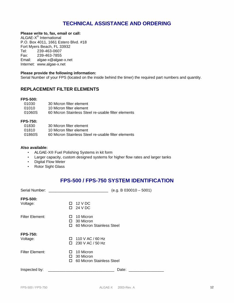
TECHNICAL ASSISTANCE AND ORDERING
Please write to, fax, email or call: ALGAE-X® International P.O. Box 4011, 1661 Estero Blvd. #18 Fort Myers Beach, FL 33932 Tel: 239-463-0607 Fax: 239-463-7855 Email: [email protected] Internet: www.algae-x.net Please provide the following information: Serial Number of your FPS (located on the inside behind the timer) the required part numbers and quantity.
REPLACEMENT FILTER ELEMENTS FPS-500: 01030 30 Micron filter element 01010 10 Micron filter element 01060S 60 Micron Stainless Steel re-usable filter elements FPS-750: 01830 30 Micron filter element 01810 10 Micron filter element 01860S 60 Micron Stainless Steel re-usable filter elements Also available:
• ALGAE-X® Fuel Polishing Systems in kit form • Larger capacity, custom designed systems for higher flow rates and larger tanks • Digital Flow Meter • Rotor Sight Glass
FPS-500 / FPS-750 SYSTEM IDENTIFICATION
Serial Number: ___________________________ (e.g. B 030010 – 5001) FPS-500: Voltage: o 12 V DC
o 24 V DC Filter Element: o 10 Micron o 30 Micron o 60 Micron Stainless Steel FPS-750: Voltage: o 110 V AC / 60 Hz o 230 V AC / 50 Hz Filter Element: o 10 Micron o 30 Micron o 60 Micron Stainless Steel Inspected by: ______________________________ Date: ________________