FPGA Implementation of Scan-to-Scan Discriminator for … · FPGA Implementation of Scan-to-Scan...
12
International Journal of Engineering Research and Development e-ISSN: 2278-067X, p-ISSN: 2278-800X, www.ijerd.com Volume 10, Issue 11 (November 2014), PP.39-50 39 FPGA Implementation of Scan-to-Scan Discriminator for the Detection of Marine Targets 1 Anala M, 2 Fathima Jabeen, 3 Vikram Thakur 1 Assistant Professor, Department of ECE, KSSEM, Bangalore, India. 2 Professor and HOD, Department of ECE, KSSEM, Bangalore, India. 3 Scientist, LRDE, DRDO, Bangalore, India. Abstract:- For an operational radar, backscatter of the transmitted signal by the elements of the sea surface often places severe limits on the detect ability of returns from ships, missiles, navigation buoys, and other targets sharing the radar resolution cell with the sea surface. These interfering signals are commonly referred to as sea clutter, or sea echo. Maritime surveillance radar experiences serious limitations imposed on their performance by unwanted sea clutter. In the marine environment, sea clutter might occur at a random position in one scan but not in the next or subsequent scans. In contrast, targets will appear from scan to scan with essentially the same amplitude. The scan-to-scan discriminator eliminates “spiky” clutter by using one of the 3 approaches. They are: 1. Fixed Threshold. 2. Cell Averaging Constant False Alarm Rate (CA- CFAR). 3. Clutter Map. The output of the scan-to-scan discriminator is then used to tag the speed of small marine targets and gating approach is used to tag the speed of large marine targets. A Field Programmable Gate Array (FPGA) based hardware architecture for the scan-to-scan discriminator using Fixed Threshold and Clutter Map for radar target detections is developed. Compilation reports and board programming files have been obtained using Quartus II 13.1. Altera-Stratix V FPGA signal processing board has been used as a target device for the implementation purpose. Keywords:- Radar, scan-to-scan discriminator, sea clutter, fixed threshold, clutter map, CA-CFAR. I. INTRODUCTION Radar detection performance is often deteriorated due to the presence of sea clutter. Clutter is the term used to denote unwanted echoes from the natural environment [14]. It implies that these unwanted echoes “clutter” the radar and make difficult the detection of wanted targets. Clutter includes echoes from land, sea, weather (particularly rain), birds and insects. Large clutter echoes can mask echoes form desired targets and limit radar capability [1]. In addition to any possible clutter there will also be always noise. The total signal competing with the target return is the clutter plus noise. In practice there is often either no clutter or clutter dominates or the noise can be ignored. In the first case the radar is said to be Noise limited, in the second it is Clutter Limited. Sea clutter limits the performance of radar. For sea clutter, the k-distribution is said to be made of two components. There is a fast varying component, with a correlation time of the order of 5 to 10ms. The fast component can be decorrelated pulse to pulse. It is sometimes called the “speckle component” and its statistics can be represented by Rayleigh distribution [7]. The other component has a longer decorrelation time, of the order of seconds. The slowly varying component can be represented by a gamma distribution. II. METHODS OF THRESHOLD DETECTION Detection of radar signal is based on establishing a threshold at the output of the receiver. If the receiver output is large enough to exceed the threshold, a target is said to be present. If the receiver output is not of sufficient amplitude to cross the threshold, only unwanted signal is said to be present. This is called threshold detection. Three approaches can be adopted in order to determine the threshold levels. They are: 1. Fixed Threshold. 2. CA-CFAR. 3. Clutter Map.
Transcript of FPGA Implementation of Scan-to-Scan Discriminator for … · FPGA Implementation of Scan-to-Scan...
International Journal of Engineering Research and Development
e-ISSN: 2278-067X, p-ISSN: 2278-800X, www.ijerd.com
Volume 10, Issue 11 (November 2014), PP.39-50
39
FPGA Implementation of Scan-to-Scan Discriminator for the
Detection of Marine Targets
1Anala M,
2Fathima Jabeen,
3Vikram Thakur
1Assistant Professor, Department of ECE, KSSEM, Bangalore, India.
2Professor and HOD, Department of ECE, KSSEM, Bangalore, India.
3Scientist, LRDE, DRDO, Bangalore, India.
Abstract:- For an operational radar, backscatter of the transmitted signal by the elements of the sea surface
often places severe limits on the detect ability of returns from ships, missiles, navigation buoys, and other
targets sharing the radar resolution cell with the sea surface. These interfering signals are commonly referred to
as sea clutter, or sea echo. Maritime surveillance radar experiences serious limitations imposed on their
performance by unwanted sea clutter.
In the marine environment, sea clutter might occur at a random position in one scan but not in the next or
subsequent scans. In contrast, targets will appear from scan to scan with essentially the same amplitude. The
scan-to-scan discriminator eliminates “spiky” clutter by using one of the 3 approaches. They are:
1. Fixed Threshold.
2. Cell Averaging Constant False Alarm Rate (CA- CFAR).
3. Clutter Map.
The output of the scan-to-scan discriminator is then used to tag the speed of small marine targets and gating
approach is used to tag the speed of large marine targets.
A Field Programmable Gate Array (FPGA) based hardware architecture for the scan-to-scan discriminator using
Fixed Threshold and Clutter Map for radar target detections is developed. Compilation reports and board
programming files have been obtained using Quartus II 13.1. Altera-Stratix V FPGA signal processing board
has been used as a target device for the implementation purpose.
Keywords:- Radar, scan-to-scan discriminator, sea clutter, fixed threshold, clutter map, CA-CFAR.
I. INTRODUCTION Radar detection performance is often deteriorated due to the presence of sea clutter. Clutter is the term
used to denote unwanted echoes from the natural environment [14]. It implies that these unwanted echoes
“clutter” the radar and make difficult the detection of wanted targets. Clutter includes echoes from land, sea,
weather (particularly rain), birds and insects. Large clutter echoes can mask echoes form desired targets and
limit radar capability [1]. In addition to any possible clutter there will also be always noise. The total signal
competing with the target return is the clutter plus noise. In practice there is often either no clutter or clutter
dominates or the noise can be ignored. In the first case the radar is said to be Noise limited, in the second it is
Clutter Limited.
Sea clutter limits the performance of radar. For sea clutter, the k-distribution is said to be made of two
components. There is a fast varying component, with a correlation time of the order of 5 to 10ms. The fast
component can be decorrelated pulse to pulse. It is sometimes called the “speckle component” and its statistics
can be represented by Rayleigh distribution [7]. The other component has a longer decorrelation time, of the
order of seconds. The slowly varying component can be represented by a gamma distribution.
II. METHODS OF THRESHOLD DETECTION Detection of radar signal is based on establishing a threshold at the output of the receiver. If the
receiver output is large enough to exceed the threshold, a target is said to be present. If the receiver output is not
of sufficient amplitude to cross the threshold, only unwanted signal is said to be present. This is called threshold
detection. Three approaches can be adopted in order to determine the threshold levels. They are:
1. Fixed Threshold.
2. CA-CFAR.
3. Clutter Map.
FPGA Implementation of Scan-to-Scan Discriminator for the Detection of Marine Targets
40
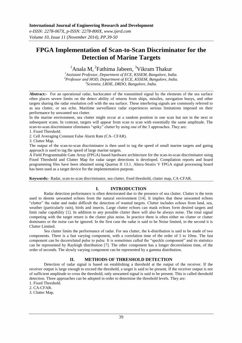
A. Fixed Threshold
In this case, the signal is compared with a fixed threshold and targets are detected whenever the signal
exceeds this threshold. If the threshold level is set properly, the receiver output should not normally exceed the
threshold if noise plus clutter alone were present, but the output would exceed the threshold if a strong target
echo signal were present.
Fig.1 Detection of target using fixed threshold.
If the threshold level were set too low, the unwanted signal might exceed it and be mistaken for a target
[14]. This is called false alarm. If the threshold were set too high, unwanted signal might not be large enough to
cause false alarms, but weak target echoes might not exceed the threshold and would not be detected. When this
occurs, it is called a missed detection.
B. CA-CFAR
The CFAR processor provides considerable better performance than the fixed processor when it comes
to following the varying mean level of the clutter. However, in some cases, such as the very spiky or weak
clutter, it may be impossible to follow the clutter mean variations. Under these conditions, Ideal fixed processor
is more optimal.
A false alarm is “an erroneous radar target detection decision caused by noise or other interfering
signals exceeding the detection threshold”. In general, it is an indication of the presence of a radar target when
there is no valid target [3]. The False Alarm Rate (FAR) is calculated using the following formula:
FAR =false targets per PRT/Number of range cells
False alarms are generated when thermal noise exceeds a pre-set threshold level, by the presence of
spurious signals, or by equipment malfunction. If the detection threshold is set too high, there will be very few
false alarms, but the signal-to-noise ratio required will inhibit detection of valid targets. If the threshold is set
too low, the large number of false alarms will mask detection of valid targets.
1. Threshold is set too high: Probability of Detection = 20%
2. Threshold is set optimal: Probability of Detection = 80%
But one false alarm arises!
False alarm rate = 1 / 666 = 1,5 •10-3
3. Threshold is set too low: a large number of false alarms arise!
4. Threshold is set variable: constant false-alarm rate.
The false alarm rate depends on the level of all interferences, like noise, clutter or jamming. Near the
radar site the influence of the fixed clutter is higher than the noise level. At large distances the influence of the
noise level is higher. To achieve a higher probability of detection in large distances by using a lower threshold
level, the false alarm rate rises at close range.
Constant false alarm rate (CFAR) detection refers to a common form of adaptive algorithm used in
radar systems to detect target returns against a background of noise, clutter and interference [2]. In the radar
receiver, the returning echoes are typically received by the antenna, amplified, down-converted and then passed
FPGA Implementation of Scan-to-Scan Discriminator for the Detection of Marine Targets
41
through detector circuitry that extracts the envelope of the signal. This signal is proportional to the power of the
received echo and comprises the wanted echo signal and the unwanted power from external clutter and
interference and internal receiver noise. The role of the constant false alarm rate circuitry is to determine the
power threshold above which any return can be considered to probably originate from a target. If this threshold
is too low, then more targets will be detected at the expense of increased numbers of false alarms and vice-versa,
but the number of false alarms will also be low[14]. In most radar detectors, the threshold is set in order to
achieve a required probability of false alarm.
If the background against which targets are to be detected is constant with time and space, then a fixed
threshold level can be chosen that provides a specified probability of false alarm, governed by the probability
density function of the noise, which is usually assumed to be Gaussian [2]. The probability of detection is then a
function of the signal-to-noise ratio of the target return.. In this case, a changing threshold can be used, where
the threshold level is raised and lowered to maintain a constant probability of false alarm. This is known as
constant false alarm rate (CFAR) detection.
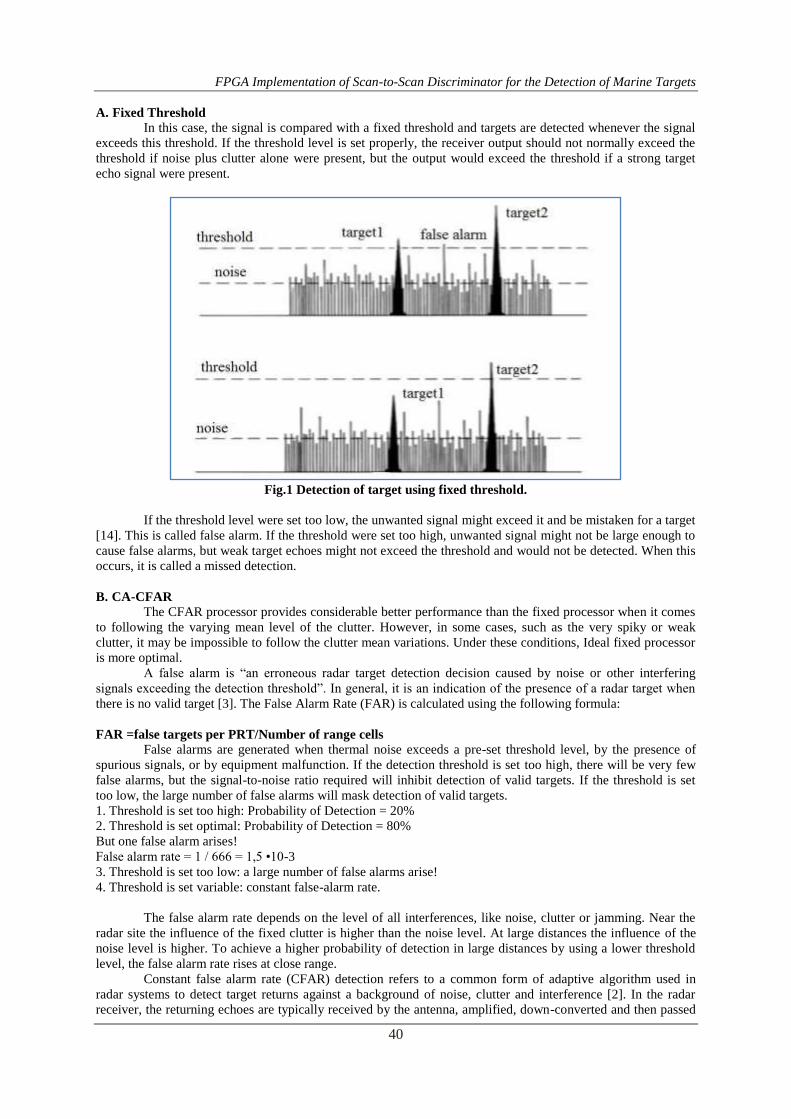
In most simple CFAR detection schemes, the threshold level is calculated by estimating the level of the
noise floor around the cell under test (CUT). This can be found by taking a block of cells around the CUT and
calculating the average power level. To avoid corrupting this estimate with power from the CUT itself, cells
immediately adjacent to the CUT are normally ignored (and referred to as "guard cells"). A target is declared
present in the CUT if it is both greater than all its adjacent cells and greater than the local average power level.
The estimate of the local power level may sometimes be increased slightly to allow for the limited sample size.
This simple approach is called a cell-averaging CFAR (CA-CFAR).
Fig.2 Cell Averaging CFAR (CA-CFAR).
C. Clutter Map
Clutter map stores the magnitude of clutter echoes in a digital memory. The clutter echo stored in each
cell of the map can be used to establish a threshold. It is therefore, a form of CFAR [5]. The clutter map
establishes the thresholds used for detecting the targets. On each scan, one eighth of the present output is added
to the seven eighths of the value stored in the clutter map. Since clutter can change with time, the value of the
clutter in each cell is uploaded periodically by averaging over a large number of scans [6]. The larger the
number of scans the more accurate will be the estimate of the clutter and the less the effect of a target that
moves through the cell. The map is built up in a recursive manner. About 3 to 10 scans are required to establish
a steady state values. The values in the clutter map are multiplied by an appropriate constant to establish the
threshold which allows the detection of targets.
A clutter map has an advantage over the CA-CFAR in that it is not affected by edge effects. The
response of the clutter map will be reduced when a target of slow speed remains within the cell long enough to
affect the threshold. This effect can be reduced by making the map cell greater than the radar resolution cell.
Increasing the size of the clutter map cell should not be carried too far, however, since it reduces the interclutter
visibility.
FPGA Implementation of Scan-to-Scan Discriminator for the Detection of Marine Targets
42
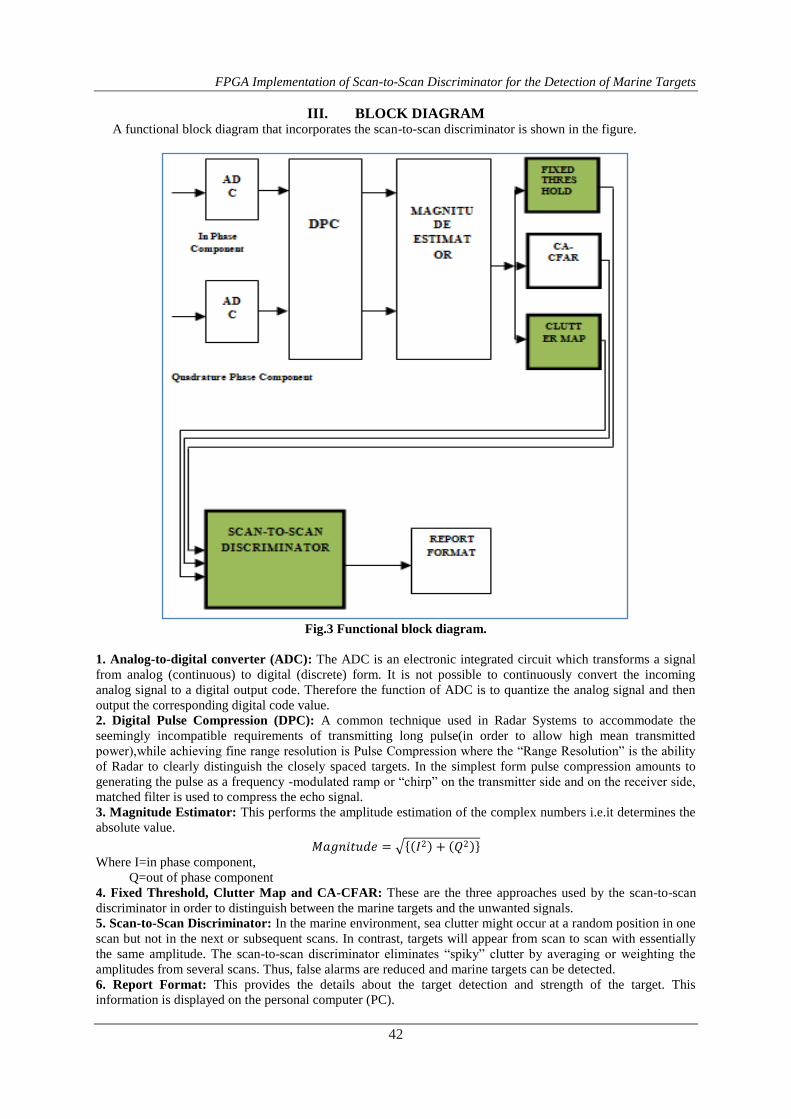
III. BLOCK DIAGRAM A functional block diagram that incorporates the scan-to-scan discriminator is shown in the figure.
Fig.3 Functional block diagram.
1. Analog-to-digital converter (ADC): The ADC is an electronic integrated circuit which transforms a signal
from analog (continuous) to digital (discrete) form. It is not possible to continuously convert the incoming
analog signal to a digital output code. Therefore the function of ADC is to quantize the analog signal and then
output the corresponding digital code value.
2. Digital Pulse Compression (DPC): A common technique used in Radar Systems to accommodate the
seemingly incompatible requirements of transmitting long pulse(in order to allow high mean transmitted
power),while achieving fine range resolution is Pulse Compression where the “Range Resolution” is the ability
of Radar to clearly distinguish the closely spaced targets. In the simplest form pulse compression amounts to
generating the pulse as a frequency -modulated ramp or “chirp” on the transmitter side and on the receiver side,
matched filter is used to compress the echo signal.
3. Magnitude Estimator: This performs the amplitude estimation of the complex numbers i.e.it determines the
absolute value.
𝑀𝑎𝑔𝑛𝑖𝑡𝑢𝑑𝑒 = 𝐼2 + 𝑄2 Where I=in phase component,
Q=out of phase component
4. Fixed Threshold, Clutter Map and CA-CFAR: These are the three approaches used by the scan-to-scan
discriminator in order to distinguish between the marine targets and the unwanted signals.
5. Scan-to-Scan Discriminator: In the marine environment, sea clutter might occur at a random position in one
scan but not in the next or subsequent scans. In contrast, targets will appear from scan to scan with essentially
the same amplitude. The scan-to-scan discriminator eliminates “spiky” clutter by averaging or weighting the
amplitudes from several scans. Thus, false alarms are reduced and marine targets can be detected.
6. Report Format: This provides the details about the target detection and strength of the target. This
information is displayed on the personal computer (PC).
FPGA Implementation of Scan-to-Scan Discriminator for the Detection of Marine Targets
43
IV. METHODOLOGY The scan-to-scan discriminator uses one of the three approaches mentioned below in order to
distinguish between the marine the targets and the unwanted signals.
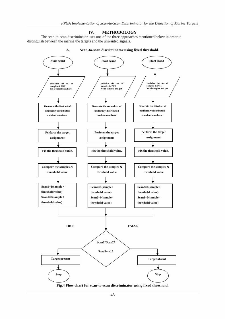
A. Scan-to-scan discriminator using fixed threshold.
Fig.4 Flow chart for scan-to-scan discriminator using fixed threshold.
TRUE FALSE
Target absent
Stop
Target present
Stop
Scan1*Scan2*
Scan3= =1?
Scan3=1(sample>
threshold value)
Scan3=0(sample<
threshold value)
Scan2=1(sample>
threshold value)
Scan2=0(sample<
threshold value)
Scan1=1(sample>
threshold value)
Scan1=0(sample<
threshold value)
Compare the samples &
threshold value
Compare the samples &
threshold value
Compare the samples &
threshold value
Fix the threshold value. Fix the threshold value. Fix the threshold value.
Perform the target
assignment
Perform the target
assignment
Perform the target
assignment
Generate the third set of
uniformly distributed
random numbers.
Generate the second set of
uniformly distributed
random numbers.
Generate the first set of
uniformly distributed
random numbers.
Initialize the no. of
samples & PRT
No of samples and prt
Initialize the no. of
samples & PRT
No of samples and prt
Start scan3
Start scan2
Start scan1
Initialize the no. of
samples & PRT
No of samples and prt
FPGA Implementation of Scan-to-Scan Discriminator for the Detection of Marine Targets
44
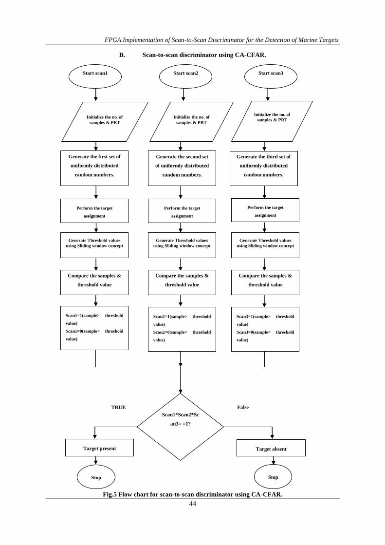
B. Scan-to-scan discriminator using CA-CFAR.
Fig.5 Flow chart for scan-to-scan discriminator using CA-CFAR.
Scan1*Scan2*Sc
an3= =1?
Target present
Target absent
Stop Stop
Generate Threshold values
using Sliding window concept
Scan1=1(sample> threshold
value)
Scan1=0(sample< threshold
value)
Compare the samples &
threshold value
Compare the samples &
threshold value
Compare the samples &
threshold value
Scan2=1(sample> threshold
value)
Scan2=0(sample< threshold
value)
Scan3=1(sample> threshold
value)
Scan3=0(sample< threshold
value)
Generate the first set of
uniformly distributed
random numbers.
Perform the target
assignment
Perform the target
assignment
Perform the target
assignment
Generate the second set
of uniformly distributed
random numbers.
Generate the third set of
uniformly distributed
random numbers.
Initialize the no. of
samples & PRT Initialize the no. of
samples & PRT
Initialize the no. of
samples & PRT
Start scan1
Start scan2
Start scan3
Generate Threshold values
using Sliding window concept
Generate Threshold values
using Sliding window concept
TRUE False
FPGA Implementation of Scan-to-Scan Discriminator for the Detection of Marine Targets
45
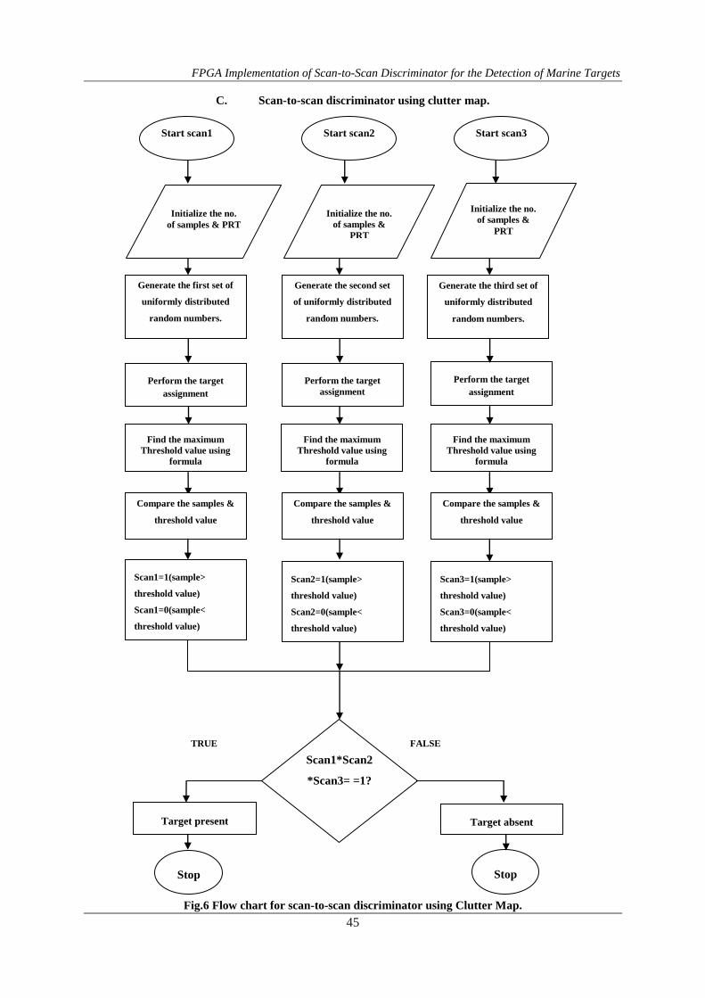
C. Scan-to-scan discriminator using clutter map.
Fig.6 Flow chart for scan-to-scan discriminator using Clutter Map.
Scan1*Scan2
*Scan3= =1?
Target present
Target absent
Stop Stop
Find the maximum
Threshold value using
formula
Scan1=1(sample>
threshold value)
Scan1=0(sample<
threshold value)
Compare the samples &
threshold value
Compare the samples &
threshold value
Compare the samples &
threshold value
Scan2=1(sample>
threshold value)
Scan2=0(sample<
threshold value)
Scan3=1(sample>
threshold value)
Scan3=0(sample<
threshold value)
Generate the first set of
uniformly distributed
random numbers.
Perform the target
assignment
Perform the target
assignment
Perform the target
assignment
Generate the second set
of uniformly distributed
random numbers.
Generate the third set of
uniformly distributed
random numbers.
Initialize the no.
of samples &
PRT
Initialize the no.
of samples & PRT
Initialize the no.
of samples &
PRT
Start scan1
Start scan2
Start scan3
Find the maximum
Threshold value using
formula
Find the maximum
Threshold value using
formula
TRUE FALSE
FPGA Implementation of Scan-to-Scan Discriminator for the Detection of Marine Targets
46
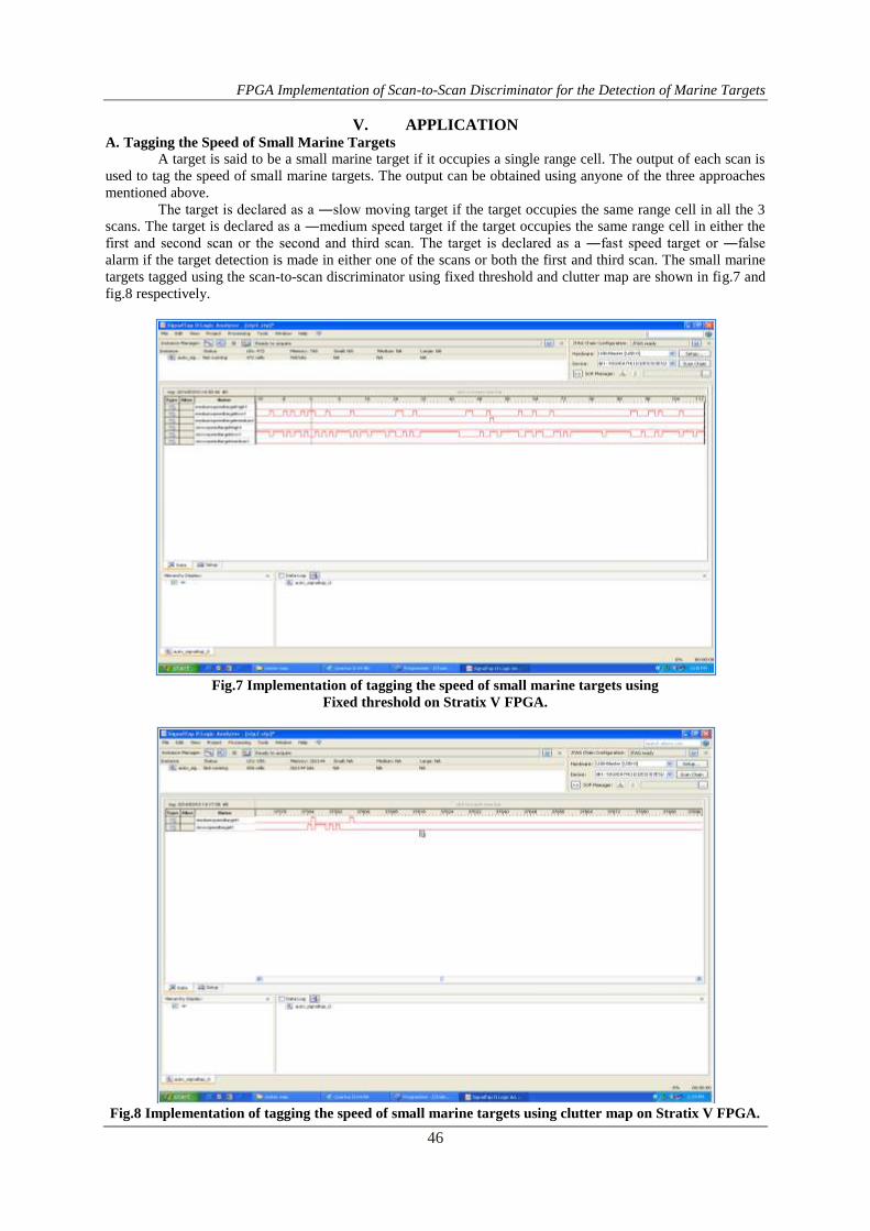
V. APPLICATION A. Tagging the Speed of Small Marine Targets
A target is said to be a small marine target if it occupies a single range cell. The output of each scan is
used to tag the speed of small marine targets. The output can be obtained using anyone of the three approaches
mentioned above.
The target is declared as a ―slow moving target if the target occupies the same range cell in all the 3
scans. The target is declared as a ―medium speed target if the target occupies the same range cell in either the
first and second scan or the second and third scan. The target is declared as a ―fast speed target or ―false
alarm if the target detection is made in either one of the scans or both the first and third scan. The small marine
targets tagged using the scan-to-scan discriminator using fixed threshold and clutter map are shown in fig.7 and
fig.8 respectively.
Fig.7 Implementation of tagging the speed of small marine targets using
Fixed threshold on Stratix V FPGA.
Fig.8 Implementation of tagging the speed of small marine targets using clutter map on Stratix V FPGA.

FPGA Implementation of Scan-to-Scan Discriminator for the Detection of Marine Targets
47
B. Tagging the Speed of Large Marine Targets using Gating Approach
A target is said to be a large marine target if it occupies two or more range cells. The output of each
scan is used to tag the speed of small marine targets. The output can be obtained using anyone of the three
approaches mentioned above.
Fig.9 Stationary target since the target remains at the same range cell in all three scans.
Fig.10 Slow speed target since the target moves from range cell 1 to 3 in three scans.
Fig.11 Medium speed target since the target moves from range cell 1 to 3 in two scans.
FPGA Implementation of Scan-to-Scan Discriminator for the Detection of Marine Targets
48
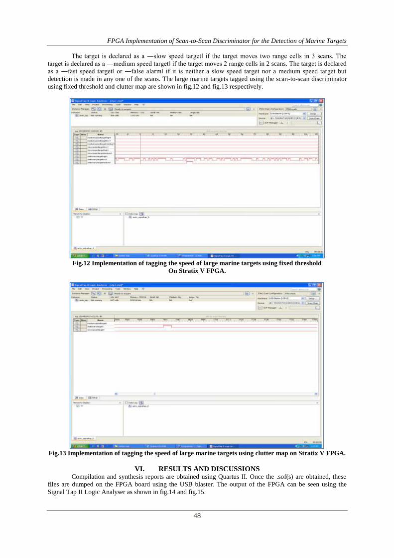
The target is declared as a ―slow speed target‖ if the target moves two range cells in 3 scans. The
target is declared as a ―medium speed target‖ if the target moves 2 range cells in 2 scans. The target is declared
as a ―fast speed target‖ or ―false alarm‖ if it is neither a slow speed target nor a medium speed target but
detection is made in any one of the scans. The large marine targets tagged using the scan-to-scan discriminator
using fixed threshold and clutter map are shown in fig.12 and fig.13 respectively.
Fig.12 Implementation of tagging the speed of large marine targets using fixed threshold
On Stratix V FPGA.
Fig.13 Implementation of tagging the speed of large marine targets using clutter map on Stratix V FPGA.
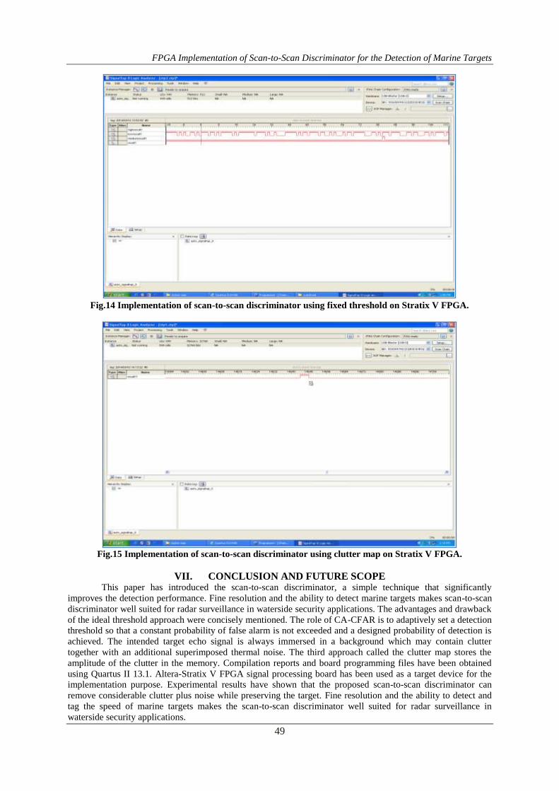
VI. RESULTS AND DISCUSSIONS Compilation and synthesis reports are obtained using Quartus II. Once the .sof(s) are obtained, these
files are dumped on the FPGA board using the USB blaster. The output of the FPGA can be seen using the
Signal Tap II Logic Analyser as shown in fig.14 and fig.15.
FPGA Implementation of Scan-to-Scan Discriminator for the Detection of Marine Targets
49
Fig.14 Implementation of scan-to-scan discriminator using fixed threshold on Stratix V FPGA.
Fig.15 Implementation of scan-to-scan discriminator using clutter map on Stratix V FPGA.
VII. CONCLUSION AND FUTURE SCOPE This paper has introduced the scan-to-scan discriminator, a simple technique that significantly
improves the detection performance. Fine resolution and the ability to detect marine targets makes scan-to-scan
discriminator well suited for radar surveillance in waterside security applications. The advantages and drawback
of the ideal threshold approach were concisely mentioned. The role of CA-CFAR is to adaptively set a detection
threshold so that a constant probability of false alarm is not exceeded and a designed probability of detection is
achieved. The intended target echo signal is always immersed in a background which may contain clutter
together with an additional superimposed thermal noise. The third approach called the clutter map stores the
amplitude of the clutter in the memory. Compilation reports and board programming files have been obtained
using Quartus II 13.1. Altera-Stratix V FPGA signal processing board has been used as a target device for the
implementation purpose. Experimental results have shown that the proposed scan-to-scan discriminator can
remove considerable clutter plus noise while preserving the target. Fine resolution and the ability to detect and
tag the speed of marine targets makes the scan-to-scan discriminator well suited for radar surveillance in
waterside security applications.
FPGA Implementation of Scan-to-Scan Discriminator for the Detection of Marine Targets
50
The discussion in this paper has concentrated on the three threshold detection techniques and the scan-
to-scan discriminator which in turn uses these three approaches to detect the marine targets. An important aspect
of the future radars is likely to be their ability to use the scan-to-scan discriminator in order to tag the speed of
marine targets i.e. tag the speed of both small marine targets and large marine targets once the target detection is
achieved. The output of the scan-to-scan discriminator can then be used to classify the marine targets as
stationary, slow speed, medium speed and fast speed targets. The scan-to-scan discriminator can be enhanced
further in order to implement the following features. They are: to design the architecture and implement the CA-
CFAR; to distinguish between the fast moving marine targets and false alarms; to determine the range and the
angular direction of marine targets.
REFERENCES [1]. Ward K D, Baker C J, Watts S, “Maritime surveillance radar, Part I: Radar scattering from the ocean
surface”, IEE Proceedings on Radar and Signal Processing, Volume 137-Issue: 2, April 1990.
[2]. Watts S, Baker C J, Ward K D, "Maritime surveillance radar, Part II: Detection performance prediction
in sea clutter", Radar and Signal Processing, IEE Proceedings F, Volume 137 -Issue: 2, April 1990.
[3]. Merrill I. Skolnik, “Introduction to Radar Systems”, McGraw-Hill Publications, 3 edition, August
2000.
[4]. Valentina Ravenni, “Performance Evaluations of Frequency Diversity Radar System”, 37th European
Microwave Conference, October 2007.
[5]. Jens Christian Pedersen, “SCANTER 5000 and 6000 Solid State Radar: Utilisation of the SCANTER
5000 and 6000 series next generation solid state, coherent, frequency diversity and time diversity radar
with software defined functionality for security applications”, Waterside Security Conference (WSS),
2010.
[6]. Perez F, Asensio A, Gismero J, Alonso J I, Monje J M, Casanova F, Cortijo R, Perez-Ojeda J
F,"ARIES: A High Resolution Shipboard Radar", Radar Conference, IEEE, 2002.
[7]. Musicki D, Suvorova S, Morelande M, Moran B, “Clutter map and target tracking”, Information
Fusion, 2005 8th International Conference, Volume 1, July 2005.
[8]. Denny.M, “Simulating sea clutter via the compound-k distribution”, Radar System Modelling, IEE
Colloquium, October 1998.
[9]. C. Bouvier, L. Martinet, G. Favier, M. Artaud, “Simulation of radar sea clutter using autoregressive
modelling and K-distribution”, Radar Conference, 1995.
[10]. Abdel-Nabi M.A, Seddik K.G, El-Badaway, “Spiky sea and constant false alarm rate processing in
high-resolution maritime radar systems”, International Conference on Computer and Communication
Engineering (ICCCE), 2012.
[11]. Roberto Perez-Andrade, Rene Cumplido, Claudia Feregrino-Uribe, Fernando Martin Del Campo, “A
Versatile Hardware Architecture for a Constant False Alarm Rate Processor Based on a Linear
Insertion Sorter”.
[12]. Gandhi P.P., Kassam S.A., “Analysis of CFAR Processors in Nonhomogeneous Background”, IEEE
Transactions on Aerospace and Electronic Systems, vol. 24, 1988.
[13]. Lei Zhao, Weixian Liu, Xin Wu, Fu. J. S. “A Novel Approach for CFAR Design”, Proceedings of the
IEEE, Radar Conference, 2001.
[14]. Mark A. Richards, James A. Scheer, William A. Holm, “Principles of Modern Radar: Basic
Principles”, SciTech publishing, 10 edition, 2010.
[15]. Lehtomaki J.J, Vartiainen J, Juntti M, Saarnisaari H, “CFAR Outlier Detection With Forward
Methods”, IEEE Transactions on Signal Processing, 2007.
[16]. N. Moazen, M. R. Akhavan-Sarraf, “A Robust CFAR Algorithm In Non- Homogenous Environments”,
IET International Conference on Radar Systems, 2007.
[17]. Meng Xiangwei, Qu Fuyong, “Adaptive clutter map detector in nonhomogeneous environment”, IEEE
10th International Conference on Signal Processing (ICSP), 2010.
[18]. Darko Musicki, Sofia Suvorova, Mark Morelande and Bill Moran, “Clutter Map and Target Tracking”,
7th International Conference on Information Fusion (FUSION), 2005.