FPGA Implementation of Optimized DES Encryption Algorithm on Spartan 3E
5
International Journal of Scientific & Engineering Research, Volume 1, Issue 1, October-2010 FPGA Implemen tation of Optimized DES Encryption Algorithm on Spartan 3E Amandee p Singh, Manu Bansal Abstract - Data Security is an important parameter for the industries. It can be achieved by Encryption algorithms which are used to prevent unauthorized access of data. Cryptography is the science of keeping data transfer secure, so that eavesdroppers (or attackers) cannot decipher the transmitted message. In this paper the DES algorithm is optimized using Xilinx software and implemented on Spartan 3E FPGA kit. The paper deals with various parameters such as variable key length, key generation mechanism, etc. used in order to provide optimized results. Key Words - Encryption, Hacker, Key, S-boxes, FPGA —————————— —————————— 1 INTRODUCTION Cryptography includes two basic components: Encryption algorithm and Keys. If sender and recipient use the same ke y then it is known as symmetrical or private key cryptography. It is always suitable for long data streams. Such system is difficult to use in practice be cause the sender and rec ei ve r must know the key. It also requires sending the keys over a secure channel from sender to recipient [4]. The question is that if secure channel already exist then transmit the data over the same channel. On the other hand, if different keys are used by sender and recipient then it is known as asymmetrical or public key cryptography. The key used for encryption is called the public key and the key used for decryption is called the private key. Such technique is used for short data streams and also requires more time to encrypt the data [3]. To encr yp t a message, a pu bli c ke y can be used by anyone, but the owner having private key can only decrypt it. There is no need for a secure communication ch an ne l fo r the tr ansmis sion of th e enc rypti on ke y. Asymmetric algorithms are slower than symmetric algorithms and asymmetric algorithms cannot be applied to variable-length streams of data. Section 1 includes the introduction of cryptography. Section 2 describes the cryptography techniques. Section 3 includes the analysis and implementation of DES Algorithm using Xilinx software. Conclusion and Future work has been included in Section 4. 2 CRYPTOGRAPHY TECHNIQUES There are two techniques used for data encryption and decryption, which are: 2.1 Symmetric Cryptography If sender and recipien t use the same key then it is known as symmetrical or private key cryptography. It is always suitable for long data streams. Such system is difficult to use in practice because the sender and receiver must know the key. It also requires s ending the keys over a secure channel from sender to recipient. There are two methods that are used in symmetric key cryptography: block and stream. Th e bl ock met ho d di vi de s a large data set into bl ocks (based on predefined size or the key size), encrypts each block separately and finally combines blocks to produce encrypted data. The stream method encrypts the data as a stream of bits without separating the data into blocks. The stream of bits from the data is encrypted sequentially using some of the results from the previous bit until all the bits in the data are encrypted as a whole. 2.2 Asymmetric Cryptography If sender and recipient use different keys then it is known as asymmetrical or public key cryptography. The key used for enc ryp tio n is called the public key and the key used for decryption is called the private key. Such technique is used for short data streams and also requires more time to encrypt the data. Asymmetric encryption techniques are almost 1000 times slower than symmetric techniques, because they require more computational processing power. To get the benefits of both methods, a hybrid technique is usually used. In this technique, asymmetric encryption is used to exchange the secret key; symmetric encryption is then used to transfer data between sender and receiver. 3 DES ALGORITHM Data Encryption Standard (DES) is a cryptographic standard that was proposed as the algorithm for the secure and secret items in 1970 and was adopted as an American federal standard by National Bureau of Standards (NBS) in 1973. DES is a block cipher, which means that during the encryption process, the plaintext is
-
Upload
ijser-issn-2229-5518- -
Category
Documents
-
view
227 -
download
0
Transcript of FPGA Implementation of Optimized DES Encryption Algorithm on Spartan 3E
8/8/2019 FPGA Implementation of Optimized DES Encryption Algorithm on Spartan 3E
http://slidepdf.com/reader/full/fpga-implementation-of-optimized-des-encryption-algorithm-on-spartan-3e 1/5
International Journal of Scientific & Engineering Research, Volume 1, Issue 1, October-2010
FPGA Implementation of Optimized DES
Encryption Algorithm on Spartan 3E
Amandeep Singh, Manu Bansal
Abstract - Data Security is an important parameter for the industries. It can be achieved by Encryption algorithms which are used to preventunauthorized access of data. Cryptography is the science of keeping data transfer secure, so that eavesdroppers (or attackers) cannotdecipher the transmitted message. In this paper the DES algorithm is optimized using Xilinx software and implemented on Spartan 3E FPGAkit. The paper deals with various parameters such as variable key length, key generation mechanism, etc. used in order to provide optimizedresults.
Key Words - Encryption, Hacker, Key, S-boxes, FPGA
—————————— ——————————
1 INTRODUCTIONCryptography includes two basic components:
Encryption algorithm and Keys. If sender and recipient
use the same key then it is known as symmetrical or
private key cryptography. It is always suitable for long
data streams. Such system is difficult to use in practice
because the sender and receiver must know the key. It
also requires sending the keys over a secure channel from
sender to recipient [4]. The question is that if secure
channel already exist then transmit the data over the
same channel.
On the other hand, if different keys are used by senderand recipient then it is known as asymmetrical or public
key cryptography. The key used for encryption is called
the public key and the key used for decryption is called
the private key. Such technique is used for short data
streams and also requires more time to encrypt the data
[3]. To encrypt a message, a public key can be used by
anyone, but the owner having private key can only
decrypt it. There is no need for a secure communication
channel for the transmission of the encryption key.
Asymmetric algorithms are slower than symmetric
algorithms and asymmetric algorithms cannot be appliedto variable-length streams of data. Section 1 includes the
introduction of cryptography. Section 2 describes the
cryptography techniques. Section 3 includes the analysis
and implementation of DES Algorithm using Xilinx
software. Conclusion and Future work has been included
in Section 4.
2 CRYPTOGRAPHY TECHNIQUES
There are two techniques used for data encryption and
decryption, which are:
2.1 Symmetric CryptographyIf sender and recipient use the same key then it is known
as symmetrical or private key cryptography. It is always
suitable for long data streams. Such system is difficult touse in practice because the sender and receiver must
know the key. It also requires sending the keys over a
secure channel from sender to recipient.
There are two methods that are used in symmetric key
cryptography: block and stream.
The block method divides a large data set into blocks
(based on predefined size or the key size), encrypts each
block separately and finally combines blocks to produce
encrypted data.
The stream method encrypts the data as a stream of bits
without separating the data into blocks. The stream of bitsfrom the data is encrypted sequentially using some of the
results from the previous bit until all the bits in the data
are encrypted as a whole.
2.2 Asymmetric CryptographyIf sender and recipient use different keys then it is known
as asymmetrical or public key cryptography. The key
used for encryption is called the public key and the key
used for decryption is called the private key. Such
technique is used for short data streams and also requires
more time to encrypt the data.
Asymmetric encryption techniques are almost 1000 times
slower than symmetric techniques, because they require
more computational processing power.
To get the benefits of both methods, a hybrid technique is
usually used. In this technique, asymmetric encryption is
used to exchange the secret key; symmetric encryption is
then used to transfer data between sender and receiver.
3 DES ALGORITHM
Data Encryption Standard (DES) is a cryptographic
standard that was proposed as the algorithm for the
secure and secret items in 1970 and was adopted as an
American federal standard by National Bureau of
Standards (NBS) in 1973. DES is a block cipher, which
means that during the encryption process, the plaintext is
8/8/2019 FPGA Implementation of Optimized DES Encryption Algorithm on Spartan 3E
http://slidepdf.com/reader/full/fpga-implementation-of-optimized-des-encryption-algorithm-on-spartan-3e 2/5
International Journal of Scientific & Engineering Research, Volume 1, Issue 1, October-2010
broken into fixed length blocks and each block is
encrypted at the same time. Basically it takes a 64 bit
input plain text and a key of 64-bits (only 56 bits are used
for conversion purpose and rest bits are used for parity
checking) and produces a 64 bit cipher text by encryption
and which can be decrypted again to get the message
using the same key. Additionally, we must highlight thatthere are four standardized modes of operation of DES:
ECB (Electronic Code book mode), CBC (Cipher Block
Chaining mode), CFB (Cipher Feed back mode) and OFB
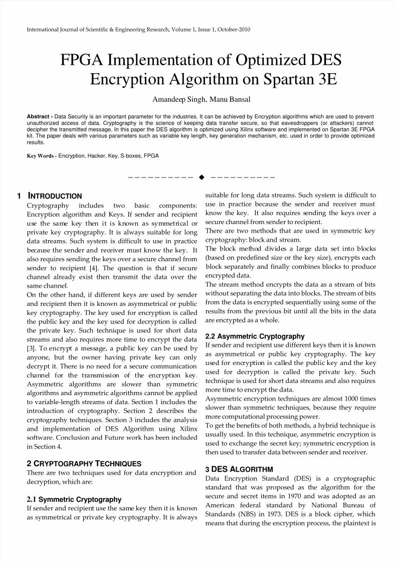
(Output Feed back mode). The general depiction of DES
encryption algorithm which consists of initial
permutation of the 64 bit plain text and then goes through
16 rounds, where each round consists permutation and
substitution of the text bit and the inputted key bit, and at
last goes through a inverse initial permutation to get the
64 bit cipher text.
Fig. 1: DES Fiestel Diagram
3.1 Steps for Algorithm
Step 1: Create 16 sub-keys, each of which is 48-bits long.
The 64-bit key is permuted according to the following
table, PC-1. Since the first entry in the table is "57", this
means that the 57th bit of the original key K becomes the
first bit of the permuted key K+. The 49th bit of the
original key becomes the second bit of the permuted key.
The 4th bit of the original key is the last bit of the
permuted key. Note only 56 bits of the original key
appear in the permuted key.
Table 1: PC-1
Example: From the original 64-bit key
K =
111111111111111000000000000000010101010101010100101
010101010101we get the 56-bit permutation
K+ =
001100111100001100110011110000110011110000110011001
10011
Next, split this key into left and right halves, C0 and D0 ,
where each half has 28 bits.
Example: From the permuted key K+, we get
C0 = 0011001111000011001100111100
D0 = 0011001111000011001100110011
With C0 and D0 defined, we now create sixteen blocks Cn
and Dn , 1<=n<=16. Each pair of blocks Cn and Dn is formedfrom the previous pair Cn-1 and Dn-1 , respectively, for n =
1, 2, … 16, using the schedule of "left shifts" of the
previous block. To do a left shift, move each bit one place
to the left, except for the first bit, which is cycled to the
end of the block.
This means, for example, C3 and D3 are obtained from C2
and D2 , respectively, by two left shifts, and C16 and D16 are
obtained from C15 and D15 , respectively, by one left shift.
In all cases, by a single left shift is meant a rotation of the
bits one place to the left, so that after one left shift the bits
in the 28 positions are the bits that were previously inpositions 2, 3,..., 28, 1.
Example: From original pair C0 and D0 we obtain:
C0 = 0011001111000011001100111100
D0 = 0011001111000011001100110011
C1 = 0110011110000110011001111000
D1 = 0110011110000110011001100110
We now form the keys Kn , for 1<=n<=16, by applying the
following permutation table to each of the concatenated
pairs CnDn. Each pair has 56 bits, but PC-2 only uses 48 of
these.
Table 2: PC-2
8/8/2019 FPGA Implementation of Optimized DES Encryption Algorithm on Spartan 3E
http://slidepdf.com/reader/full/fpga-implementation-of-optimized-des-encryption-algorithm-on-spartan-3e 3/5
International Journal of Scientific & Engineering Research, Volume 1, Issue 1, October-2010
Therefore, the first bit of Kn is the 14th bit of CnDn , the
second bit the 17th, and so on, ending with the 48th bit ofKn being the 32th bit of CnDn.
Example: For the first key we have C1D1 = 01100111
10000110 01100111 10000110 01111000 01100110 01100110
which, after we apply the permutation PC-2, becomes K1
= 0001 1011 0000 0010 1110 1111 1111 1100 0111 0000 0111
0010
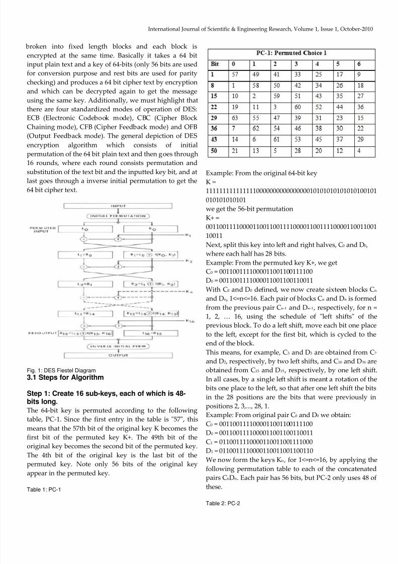
Fig. 2: Output Waveform for Key Scheduling
Step 2: Encode each 64-bit block of data
There is an initial permutation IP of the 64 bits of the
message data M. This rearranges the bits according to the
following table, where the entries in the table show the
new arrangement of the bits from their initial order.
Table 3: IP
The 58th bit of M becomes the first bit of IP. The 50th bit
of M becomes the second bit of IP. The 7th bit of M is the
last bit of IP.
Example: Applying the initial permutation to the block of
text M, given previously, we get
M = 0000 0001 0010 0011 0100 0101 0110 0111 1000 1001
1010 1011 1100 1101 1110 1111
IP = 1100 1100 0000 0000 1100 1100 1111 1111 1111 0000
1010 1010 1111 0000 1010 1010
Here the 58th bit of M is "1", which becomes the first bit of
IP. The 50th bit of M is "1", which becomes the second bit
of IP. The 7th bit of M is "0", which becomes the last bit of
IP.
Next divide the permuted block IP into a left half L0 of 32
bits, and a right half R0 of 32 bits.
Example: From IP, we get L0 and R0
L0 = 1100 1100 0000 0000 1100 1100 1111 1111
R0 = 1111 0000 1010 1010 1111 0000 1010 1010
We now proceed through 16 iterations, for 1<=n<=16,
using a function f which operates on two blocks--a data
block of 32 bits and a key Kn of 48 bits--to produce a block
of 32 bits. Let + denote XOR addition, (bit-by-bit addition
modulo 2). Then for n going from 1 to 16 we calculate
Ln = Rn-1
Rn = Ln-1 + f(Rn-1 ,Kn)
This results in a final block, for n = 16, of L16R16. That is, in
each iteration, we take the right 32 bits of the previous
result and make them the left 32 bits of the current step.
For the right 32 bits in the current step, we XOR the left 32
bits of the previous step with the calculation f .
Example: For n = 1, we have
K1 = 0001 1011 0000 0010 1110 1111 1111 1100 0111 0000
0111 0010
L1 = R0 = 1111 0000 1010 1010 1111 0000 1010 1010
R1 = L0 + f(R0 ,K1)
It remains to explain how the function f works. To
calculate f, we first expand each block Rn-1 from 32 bits to
48 bits. This is done by using a selection table that repeats
8/8/2019 FPGA Implementation of Optimized DES Encryption Algorithm on Spartan 3E
http://slidepdf.com/reader/full/fpga-implementation-of-optimized-des-encryption-algorithm-on-spartan-3e 4/5
International Journal of Scientific & Engineering Research, Volume 1, Issue 1, October-2010
some of the bits in Rn-1 We'll call the use of this selection
table the function E. Thus E(Rn-1) has a 32 bit input block,
and a 48 bit output block.
Thus the first three bits of E(Rn-1) are the bits in positions
32, 1 and 2 of Rn-1 while the last 2 bits of E(Rn-1) are the bits
in positions 32 and 1.
Example: We calculate E(R0) from R0 as follows:R0 = 1111 0000 1010 1010 1111 0000 1010 1010
E(R0) = 011110 100001 010101 010101 011110 100001
010101 010101
(Note that each block of 4 original bits has been expanded
to a block of 6 output bits.)
Next in the f calculation, we XOR the output E(Rn-1) with
the key Kn:
Kn + E(Rn-1).
Example: For K1 , E(R0), we have
K1 = 00011011 00000010 11101111 11111100 01110000
01110010E(R0) = 011110 100001 010101 010101 011110 100001
010101 010101
K1+E(R0) =
100101010001100001010101011101101000010111000111
To this point we have expanded Rn-1 from 32 bits to 48
bits, using the selection table, and XORed the result with
the key Kn . We now have 48 bits, or eight groups of six
bits. We now do something strange with each group of
six bits: we use them as addresses in tables called "S
boxes". Each group of six bits will give us an address in a
different S box. Located at that address will be a 4 bitnumber. This 4 bit number will replace the original 6 bits.
The net result is that the eight groups of 6 bits are
transformed into eight groups of 4 bits (the 4-bit outputs
from the S boxes) for 32 bits total.
Write the previous result, which is 48 bits, in the form:
Kn + E(Rn-1) =B1B2B3B4B5B6B7B8 ,
where each Bi is a group of six bits. We now calculate
S1(B1)S2(B2)S3(B3)S4(B4)S5(B5)S6(B6)S7(B7)S8(B8)
where Si(Bi) refers to the output of the i-th S box.
To repeat, each of the functions S1, S2,..., S8, takes a 6-bit
block as input and yields a 4-bit block as output. The tableto determine S1 is shown and explained below:
If S1 is the function defined in this table and B is a block of
6 bits, then S1(B) is determined as follows: The first and
last bits of B represent in base 2 a number in the decimal
range 0 to 3 (or binary 00 to 11). Let that number be i. The
middle 4 bits of B represent in base 2 a number in the
decimal range 0 to 15 (binary 0000 to 1111). Let that
number be j. Look up in the table the number in the i-th
row and j-th column. It is a number in the range 0 to 15
and is uniquely represented by a 4 bit block. That block is
the output S1(B) of S1 for the input B. For example, forinput block B = 011101 the first bit is "0" and the last bit
"1" giving 01 as the row. This is row 1. The middle four
bits are "1110". This is the binary equivalent of decimal 13,
so the column is column number 13. In row 1, column 13
appears 5. This determines the output; 5 is binary 0011, so
that the output is 0101. Hence S1(011101) = 0011.
Example: For the first round, we obtain as the output of
the eight S boxes:
K1 + E(R0)
=100101010001100001010101011101101000010111000111
S1(B1)S2(B2)S3(B3)S4(B4)S5(B5)S6(B6)S7(B7)S8(B8) = 0101 1100
1000 0010 1011 0101 1001 0111
The final stage in the calculation of f is to do a
permutation P of the S-box output to obtain the final
value of f:
f = P(S1(B1)S2(B2)...S8(B8))
P yields a 32-bit output from a 32-bit input by permuting
the bits of the input block.
Example: From the output of the eight S boxes:
S1(B1)S2(B2)S3(B3)S4(B4)S5(B5)S6(B6)S7(B7)S8(B8) = 0101 11001000 0010 1011 0101 1001 0111
we get
f = 0010 0011 0100 1010 1010 1001 1011 1011
R1 = L0 + f(R0 , K1 )
= 1100 1100 0000 0000 1100 1100 1111 1111
+ 0010 0011 0100 1010 1010 1001 1011 1011
= 1110 1111 0100 1010 0110 0101 0100 0100
In the next round, we will have L2 = R1 , which is the block
we just calculated, and then we must calculate R2 =L1 +
f(R1 , K2), and so on for 16 rounds. At the end of the
sixteenth round we have the blocks L16 and R16. We thenreverse the order of the two blocks into the 64-bit block
R16L16
and apply a final permutation IP-1 as defined by the
following table:Table 4: IP^ (-1)
That is, the output of the algorithm has bit 40 of the pre-
output block as its first bit, bit 8 as its second bit, and so
on, until bit 25 of the pre-output block is the last bit of the
output.
Example: If we process all 16 blocks using the method
defined previously, we get, on the 16th round,
8/8/2019 FPGA Implementation of Optimized DES Encryption Algorithm on Spartan 3E
http://slidepdf.com/reader/full/fpga-implementation-of-optimized-des-encryption-algorithm-on-spartan-3e 5/5
International Journal of Scientific & Engineering Research, Volume 1, Issue 1, October-2010
L16 = 0100 0011 0100 0010 0011 0010 0011 0100
R16 = 0000 1010 0100 1100 1101 1001 1001 0101
We reverse the order of these two blocks and apply the
final permutation to
R16L16 = 00001010 01001100 11011001 10010101 01000011
01000010 00110010 00110100IP-1 = 10000101 11101000 00010011 01010100 00001111
00001010 10110100 00000101
this in hexadecimal format is
69BE85B7C35D19EE.
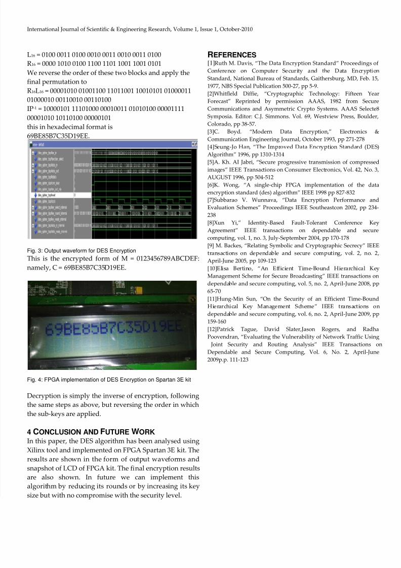
Fig. 3: Output waveform for DES Encryption
This is the encrypted form of M = 0123456789ABCDEF:
namely, C = 69BE85B7C35D19EE.
Fig. 4: FPGA implementation of DES Encryption on Spartan 3E kit
Decryption is simply the inverse of encryption, followingthe same steps as above, but reversing the order in which
the sub-keys are applied.
4 CONCLUSION AND FUTURE WORK
In this paper, the DES algorithm has been analysed using
Xilinx tool and implemented on FPGA Spartan 3E kit. The
results are shown in the form of output waveforms and
snapshot of LCD of FPGA kit. The final encryption results
are also shown. In future we can implement this
algorithm by reducing its rounds or by increasing its key
size but with no compromise with the security level.
REFERENCES[1]Ruth M. Davis, “The Data Encryption Standard” Proceedings of
Conference on Computer Security and the Data Encryption
Standard, National Bureau of Standards, Gaithersburg, MD, Feb. 15,
1977, NBS Special Publication 500-27, pp 5-9.
[2]Whitfleld Diffie, “Cryptographic Technology: Fifteen Year
Forecast” Reprinted by permission AAAS, 1982 from SecureCommunications and Asymmetric Crypto Systems. AAAS Selecte8
Symposia. Editor: C.J. Simmons. Vol. 69, Westview Press, Boulder,
Colorado, pp 38-57.
[3]C. Boyd. “Modern Data Encryption,” Electronics &
Communication Engineering Journal, October 1993, pp 271-278
[4]Seung-Jo Han, “The Improved Data Encryption Standard (DES)
Algorithm” 1996, pp 1310-1314
[5]A. Kh. AI Jabri, “Secure progressive transmission of compressed
images” IEEE Transactions on Consumer Electronics, Vol. 42, No. 3,
AUGUST 1996, pp 504-512
[6]K. Wong, “A single-chip FPGA implementation of the data
encryption standard (des) algorithm” IEEE 1998 pp 827-832
[7]Subbarao V. Wunnava, “Data Encryption Performance andEvaluation Schemes” Proceedings IEEE Southeastcon 2002, pp 234-
238
[8]Xun Yi,” Identity-Based Fault-Tolerant Conference Key
Agreement” IEEE transactions on dependable and secure
computing, vol. 1, no. 3, July-September 2004, pp 170-178
[9] M. Backes, “Relating Symbolic and Cryptographic Secrecy” IEEE
transactions on dependable and secure computing, vol. 2, no. 2,
April-June 2005, pp 109-123
[10]Elisa Bertino, “An Efficient Time-Bound Hierarchical Key
Management Scheme for Secure Broadcasting” IEEE transactions on
dependable and secure computing, vol. 5, no. 2, April-June 2008, pp
65-70
[11]Hung-Min Sun, “On the Security of an Efficient Time-BoundHierarchical Key Management Scheme” IEEE transactions on
dependable and secure computing, vol. 6, no. 2, April-June 2009, pp
159-160
[12]Patrick Tague, David Slater,Jason Rogers, and Radha
Poovendran, “Evaluating the Vulnerability of Network Traffic Using
Joint Security and Routing Analysis” IEEE Transactions on
Dependable and Secure Computing, Vol. 6, No. 2, April-June
2009p.p. 111-123