Translating Grafcet specifications into Mealy machines for ...
Upload
malik-tauqir-hasanCategory
view
37download
0
ENGR. RASHID FARID CHISHTILECTURER,DEE, FET, IIUI
WEEK 8
BEHAVIORAL MODELINGMEALY MACHINE
FPGA Based System Design
Saturday, April 15, 2023
1
www.iiu.edu.pk

With the increasing complexity of digital design, it has become vitally important to make wise design decisions early in a project.
Designers need to be able to evaluate the trade-offs of various architectures and algorithms before they decide on the optimum architecture and algorithm to implement in hardware.
Thus, architectural evaluation takes place at an algorithmic level where the designers do not necessarily think in terms of logic gates or data flow but in terms of the algorithm they wish to implement in hardware.
They are more concerned about the behavior of the algorithm and its performance.
Only after the high-level architecture and algorithm are finalized, do designers start focusing on building the digital circuit to implement the algorithm.
Verilog provides designers the ability to describe design functionality in an algorithmic manner.
In other words, the designer describes the behavior of the circuit. Thus, behavioral modeling represents the circuit at a very high level of
abstraction.www.iiu.edu.pk Saturday, April 15, 2023
Behavioral Modeling
2

There are two structured procedure statements in Verilog: always and initial. These statements are the two most basic statements in behavioral modeling.
All other behavioral statements can appear only inside these structured procedure statements.
Verilog is a concurrent programming language unlike the C programming language, which is sequential in nature.
Activity flows in Verilog run in parallel rather than in sequence. Each always and initial statement represents a separate activity flow in Verilog. Each activity flow starts at simulation time 0. The statements always and initial cannot be nested. initial Statement: All statements inside an initial statement constitute an initial block. An initial block starts at time 0, executes exactly once during a simulation, and
then does not execute again. If there are multiple initial blocks, each block starts to execute concurrently at
time 0. www.iiu.edu.pk Saturday, April 15, 2023
Structured Procedures: initial and always blocks
3

Each block finishes execution independently of other blocks. Multiple behavioral statements must be grouped, typically using the keywords
begin and end. If there is only one behavioral statement, grouping is not necessary. Following example illustrates the use of the initial statement.
module stimulus;
reg x,y, a,b, m;
initial m = 1'b0; //single statement; does not need to be grouped
initial begin #5 a = 1'b1; // multiple statements; need to be grouped
#25 b = 1'b0;
end
initial begin #10 x = 1'b0; #25 y = 1'b1;
end
initial #50 $finish;
endmodulewww.iiu.edu.pk Saturday, April 15, 2023
Structured Procedures: initial and always blocks
4

In the example, the three initial statements start to execute in parallel at time 0. If a delay #<delay> is seen before a statement, the statement is executed <delay>
time units after the current simulation time. Thus, the execution sequence of the statements inside the initial blocks will be as
follows. time statement executed
0 m = 1'b0;
5 a = 1'b1;
10 x = 1'b0;
30 b = 1'b0;
35 y = 1'b1;
50 $finish; The initial blocks are typically used for initialization, monitoring, waveforms and
other processes that must be executed only once during the entire simulation run. The following subsections discussion how to initialize values using alternate
shorthand syntax. The use of such shorthand syntax has the same effect as an initial block combined with a variable declaration.
www.iiu.edu.pk Saturday, April 15, 2023
Structured Procedures: initial and always blocks
5

Variables can be initialized when they are declared.
// Initial Value Assignment The clock variable is defined first
reg clock; initial clock = 0; // The value of clock is set to 0. Instead of the
// above method, clock variable can be initialized at the time of declaration
// This is allowed only for variables declared at module level.
reg clock = 0;
Combined Port/Data Declaration and Initialization The combined port/data declaration can also be combined with an initialization.
// Combined Port/Data Declaration and Variable Initialization
module adder (sum, co, a, b, ci);
output reg [7:0] sum = 0; // Initialize 8 bit output sum
output reg co = 0; // Initialize 1 bit output co
input [7:0] a, b;
input ci;
www.iiu.edu.pk Saturday, April 15, 2023
Structured Procedures: initial and always blocks
6

--
--
endmodule
Combined ANSI C Style Port Declaration and Initialization ANSI C style port declaration can also be combined with an initialization.
// Combined ANSI C Port Declaration and Variable Initialization
module adder ( output reg [7:0] sum = 0, // Initialize 8 bit output
output reg co = 0, // Initialize 1 bit output co
input [7:0] a, b,
input ci );
--
--
endmodule
www.iiu.edu.pk Saturday, April 15, 2023
Structured Procedures: initial and always blocks
7

always Statement All behavioral statements inside an always statement constitute an always block. The always statement starts at time 0 and executes the statements in the always
block continuously in a looping fashion. This statement is used to model a block of activity that is repeated continuously in
a digital circuit. An example is a clock generator module that toggles the clock signal every half
cycle. lock generator is active from time 0 to as long as the circuit is powered on.
// model ing a clock generator in Verilog.
module clock_gen (output reg clock);
initial clock = 1'b0; // Initialize clock at time zero
always #10 clock = ~clock; // Toggle clock every 10 unit sec
initial #1000 $finish;
endmodule
www.iiu.edu.pk Saturday, April 15, 2023
Structured Procedures: initial and always blocks
8

In previous example, the always statement starts at time 0 and executes the statement clock = ~clock every 10 time units.
Notice that the initialization of clock has to be done inside a separate initial statement.
If we put the initialization of clock inside the always block, clock will be initialized every time the always is entered.
Also, the simulation must be halted inside an initial statement. If there is no $stop or $finish statement to halt the simulation, the clock generator
will run forever.
www.iiu.edu.pk Saturday, April 15, 2023
Structured Procedures: initial and always blocks
9

Procedural assignments update values of reg, integer, real, or time variables. The value placed on a variable will remain unchanged until another procedural
assignment updates the variable with a different value. Two types of procedural assignment statements: blocking and nonblocking
Blocking Assignments: statements are executed in the order they are specified in a sequential block. The = operator is used to specify blocking assignments.
reg x, y, z; reg [15:0] reg_a, reg_b; integer count; // Blocking Example
// All behavioral statements must be inside an initial or always block
initial begin x = 0; y = 1; z = 1; // Scalar assignments
count = 0; // Assignment to integer variables
reg_a = 16'b0; reg_b = reg_a; // Initialize vectors
reg_a[2] <= #15 1'b1; // Bit select assignment with delay
reg_b[15:13] <= #10 {x, y, z}; // Assign result of concatenation
// to part select of a vector
count <= count + 1; //Assignment to an integer (increment)
endwww.iiu.edu.pk Saturday, April 15, 2023
Procedural Assignments: blocking and nonbloking
10

In this example, the statements x = 0 through reg_b = reg_a are executed sequentially at time 0. Then the three nonblocking assignments are processed at the same simulation time.
reg_a[2] = 0 is scheduled to execute after 15 units (i.e., time = 15) reg_b[15:13] = {x, y, z} is scheduled to execute after 10 time units (time = 10) count = count + 1 is scheduled to be executed without any delay (i.e., time = 0) Thus, the simulator schedules a nonblocking assignment statement to execute and
continues to the next statement in the block without waiting for the nonblocking statement to complete execution.
Typically, nonblocking assignment statements are executed last in the time step in which they are scheduled, that is, after all the blocking assignments in that time step are executed.
In the example above, we mixed blocking and nonblocking assignments to illustrate their behavior.
However, it is recommended that blocking and nonblocking assignments not be mixed in the same always block.
www.iiu.edu.pk Saturday, April 15, 2023
Procedural Assignments: blocking and nonbloking
11

nonblocking assignments are used as a method to model several concurrent data transfers that take place after a common event. Consider the following example where three concurrent data transfers take place at the positive edge of clock.
always @(posedge clock)
begin reg1 <= #1 in1;
reg2 <= @(negedge clock) in2 ^ in3;
reg3 <= #1 reg1; // The old value of reg1
end At each positive edge of clock, the following sequence takes place for the
nonblocking assignments. A read operation is performed on each right-hand-side variable, in1, in2, in3, and
reg1, at the positive edge of clock. The right-hand-side expressions are evaluated, and the results are stored internally in the simulator.
The write operations to the left-hand-side variables are scheduled to be executed at the time specified by the intra-assignment delay in each assignment, that is, schedule "write" to reg1 after 1 time unit, to reg2 at the next negative edge of clock, and to reg3 after 1 time unit.
www.iiu.edu.pk Saturday, April 15, 2023
Application of nonblocking assignments
12

The write operations are executed at the scheduled time steps. The order in which the write operations are executed is not important because the internally stored right-hand-side expression values are used to assign to the left-hand-side values.
For example, note that reg3 is assigned the old value of reg1 that was stored after the read operation, even if the write operation wrote a new value to reg1 before the write operation to reg3 was executed.
Thus, the final values of reg1, reg2, and reg3 are not dependent on the order in which the assignments are processed.
Nonblocking Statements to Eliminate Race Conditions
// Illustration 1: Two concurrent always blocks with blocking statements
always @(posedge clock) a = b;
always @(posedge clock) b = a;
// Illustration 2: Two concurrent always blocks with nonblocking statements always @(posedge clock) a <= b;
always @(posedge clock) b <= a;
www.iiu.edu.pk Saturday, April 15, 2023
Application of nonblocking assignments
13

In previous example; there is a race condition when blocking statements are used. Either a = b would be executed before b = a, or vice versa, depending on the
simulator implementation. Thus, values of registers a and b will not be swapped. Instead, both registers will get the same value (previous value of a or b), based on
the Verilog simulator implementation. However, nonblocking statements used in Illustration 2 eliminate the race
condition. At the positive edge of clock, the values of all right-hand-side variables are "read," and the right-hand-side expressions are evaluated and stored in temporary variables.
During the write operation, the values stored in the temporary variables are assigned to the left-hand-side variables.
Separating the read and write operations ensures that the values of registers a and b are swapped correctly, regardless of the order in which the write operations are performed.
Next example shows how nonblocking assignments could be emulated using blocking assignments.
www.iiu.edu.pk Saturday, April 15, 2023
Application of nonblocking assignments
14

// Emulate the behavior of nonblocking assignments by using temporary variables
// and blocking assignments
always @(posedge clock)
begin // Read operation. store values of right-hand-side
temp_a = a; // expressions in temporary variables
temp_b = b;
a = temp_b; // Write operation Assign values of temporary variables
b = temp_a; // to left-hand-side variables
end For digital design, use of nonblocking assignments is highly recommended in
places where concurrent data transfers take place after a common event. In such cases, blocking assignments can potentially cause race conditions because
the final result depends on the order in which the assignments are evaluated. Sequential logic and latches – use non blocking assignments Combinational Logic in an always block – use blocking assignments
www.iiu.edu.pk Saturday, April 15, 2023
Application of nonblocking assignments
15

// Behavioral description of 2-to-1-line multiplexer// Behavioral description of 2-to-1-line multiplexer
modulemodule mux2x1 (i0, i1, s, y); mux2x1 (i0, i1, s, y);
inputinput i0, i1, S; i0, i1, S; outputoutput y; y; regreg y; y;
alwaysalways @ (S @ (S oror i0 i0 oror i1) i1)
ifif (S == 1) (S == 1) y = i1;y = i1;
elseelse y = i0;y = i0;
endmoduleendmodule
module module mux4x1 (i0 , i1 , i2 , i3 , S , F ); mux4x1 (i0 , i1 , i2 , i3 , S , F ); // 4-to-1- line multiplexer// 4-to-1- line multiplexer
inputinput i0,i1,i2,i3; i0,i1,i2,i3; inputinput [1:0] S; [1:0] S; outputoutput F; F; regreg F; F;
alwaysalways @ (i0 @ (i0 oror i1 i1 oror i2 i2 oror i3 i3 oror S) S)
casecase (S) (S)
2'b00: F = i0;2'b00: F = i0; 2'b01: F = i1;2'b01: F = i1;
2'b10: F = i2;2'b10: F = i2; 2'b11: F = i3;2'b11: F = i3;
endcaseendcase
endmoduleendmodule
www.iiu.edu.pk Saturday, April 15, 2023
Examples
16
www.iiu.edu.pk Saturday, April 15, 2023
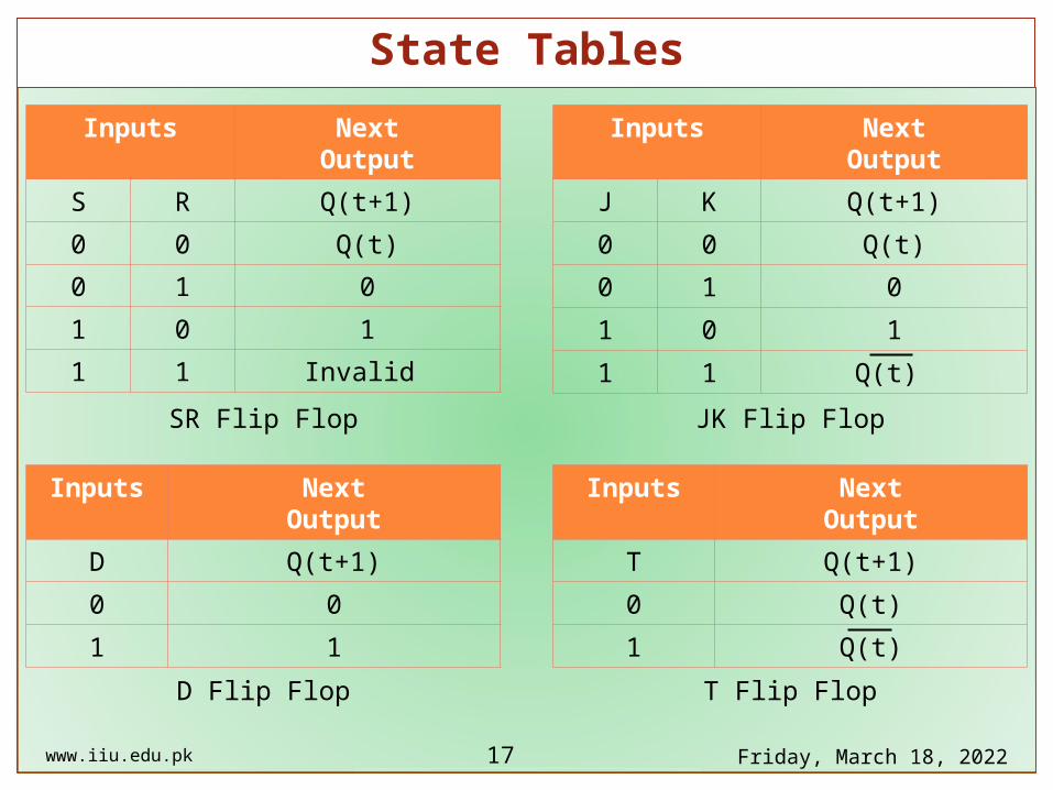
State Tables
17
Inputs NextOutput
S R Q(t+1)
0 0 Q(t)
0 1 0
1 0 1
1 1 Invalid
Inputs NextOutput
J K Q(t+1)
0 0 Q(t)
0 1 0
1 0 1
1 1 Q(t)
Inputs NextOutput
D Q(t+1)
0 0
1 1
Inputs NextOutput
T Q(t+1)
0 Q(t)
1 Q(t)
SR Flip Flop JK Flip Flop
D Flip Flop T Flip Flop

www.iiu.edu.pk Saturday, April 15, 2023
Excitation Tables
18
Output Input
Q(t) Q(t+1)
S R
0 0 0 X
0 1 1 0
1 0 0 1
1 1 X 0
Output Input
Q(t) Q(t+1)
J K
0 0 0 X
0 1 1 X
1 0 X 1
1 1 X 0
Output Input
Q(t) Q(t+1) D
0 0 0
0 1 1
1 0 0
1 1 1
SR Flip Flop JK Flip Flop
D Flip Flop T Flip Flop
Output Input
Q(t) Q(t+1) T
0 0 0
0 1 1
1 0 1
1 1 0
www.iiu.edu.pk Saturday, April 15, 2023
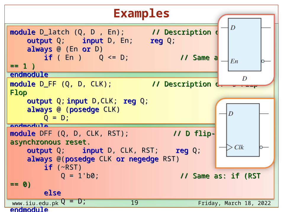
Examples
19
modulemodule D_latch (Q, D , En); D_latch (Q, D , En); // Description of D latch// Description of D latch outputoutput Q; Q; inputinput D, En; D, En; regreg Q; Q; alwaysalways @ (En @ (En oror D) D) ifif ( En ) Q <= D; ( En ) Q <= D; // Same as: if ( En == 1 )// Same as: if ( En == 1 )endmoduleendmodule
modulemodule D_FF (Q, D, CLK); D_FF (Q, D, CLK); // Description of D Flip Flop // Description of D Flip Flop outputoutput Q; Q; inputinput D,CLK; D,CLK; regreg Q; Q; alwaysalways @ ( @ (posedgeposedge CLK) CLK) Q = D;Q = D;endmoduleendmodule
modulemodule DFF (Q, D, CLK, RST); DFF (Q, D, CLK, RST); // D flip-flop with asynchronous reset.// D flip-flop with asynchronous reset. outputoutput Q; Q; inputinput D, CLK, RST; D, CLK, RST; regreg Q; Q; alwaysalways @( @(posedgeposedge CLK CLK oror negedgenegedge RST) RST) ifif (~RST) (~RST) Q = 1'b0; Q = 1'b0; // Same as: if (RST == 0)// Same as: if (RST == 0) elseelse Q = D;Q = D;endmoduleendmodule

www.iiu.edu.pk Saturday, April 15, 2023
Examples
20
module module TFF (Q, T, CLK, RST); TFF (Q, T, CLK, RST); // T flip-flop from D flip-flop// T flip-flop from D flip-flop output output Q; Q; input input T,CLK,RST; T,CLK,RST; wire wire DT;DT; assign assign DT = Q ^ T ;DT = Q ^ T ; DFF TF1 (Q, DT, CLK, RST); DFF TF1 (Q, DT, CLK, RST); // Instantiate the D flip-flop// Instantiate the D flip-flopendmoduleendmodule
modulemodule JKFF (Q, J, K, CLK, RST); JKFF (Q, J, K, CLK, RST); // JK flip-flop from D flip-flop // JK flip-flop from D flip-flop outputoutput Q; Q; inputinput J, K, CLK, RST; J, K, CLK, RST; wirewire JK; JK; assignassign JK = (J & ~Q) | (~K & Q); JK = (J & ~Q) | (~K & Q); DFF JK1 (Q, JK, CLK, RST);DFF JK1 (Q, JK, CLK, RST);endmoduleendmodule
modulemodule JK_FF (J, K, CLK, Q, Qnot); JK_FF (J, K, CLK, Q, Qnot); outputoutput Q, Qnot; Q, Qnot; inputinput J, K, CLK; J, K, CLK; regreg Q; Q; assignassign Qnot = ~ Q ; Qnot = ~ Q ; alwaysalways @ ( @ (posedgeposedge CLK) CLK) casecase ({J,K}) ({J,K}) 2'b00: Q = Q;2'b00: Q = Q; 2'b01: Q = 1'b0;2'b01: Q = 1'b0; 2'b10: Q = 1'b1;2'b10: Q = 1'b1; 2'b11: Q = ~ Q;2'b11: Q = ~ Q; endcaseendcaseendmoduleendmodule

www.iiu.edu.pk Saturday, April 15, 2023
Mealy Machine
21
A M
ealy m
ach
ine
is a fi
nite
-state
mach
ine
wh
ose
ou
tpu
t valu
es a
re d
ete
rmin
ed
both
b
y its curre
nt sta
te a
nd
the cu
rren
t inp
uts.
(Th
is is in co
ntra
st to a
Moore
mach
ine
, w
hose
ou
tpu
t valu
es a
re d
ete
rmin
ed
sole
ly b
y its curre
nt sta
te.)

// Structural description of sequential circuitmodule DFF (Q, D, CLK, RST); // D flip-flop with asynchronous reset. output Q; input D, CLK, RST; reg Q; always @(posedge CLK or negedge RST) if (~RST) Q = 1'b0; // Same as: if (RST == 0) else Q = D;endmodulemodule Mealy_Circuit (x , y, AB, CLK, RST); input x, CLK, RST; output y; output [1:0] AB; wire Da, Db,A,B; //Flip-flip input equations assign Da = (A&x) | (B&x) ; // assign Db = ~A & x ; // assign y = ~x & (A|B) ; // assign AB = {A , B} ; DFF Dffa (A, Da, CLK, RST); DFF Dffb (B, Db, CLK, RST);endmodule
www.iiu.edu.pk Saturday, April 15, 2023
Structured Programming
22

module module test_Mealy_Circuit;test_Mealy_Circuit; regreg x, CLK, RST; x, CLK, RST; wirewire Y; Y; wirewire [1:0] ABC ; [1:0] ABC ; Mealy_Circuit MC1 (x ,Y , ABC, CLK, RST); Mealy_Circuit MC1 (x ,Y , ABC, CLK, RST); initialinitial beginbegin CLK = 0; CLK = 0; repeatrepeat (30) #5 CLK = ~CLK; (30) #5 CLK = ~CLK; endend
initialinitial beginbegin RST = 1; x = 0; RST = 1; x = 0; #10 RST = 0;#10 RST = 0; #10 RST = 1;#10 RST = 1; repeatrepeat (6) #30 x = ~x; (6) #30 x = ~x; endendendmoduleendmodule
www.iiu.edu.pk Saturday, April 15, 2023
Examples
23

Input Present State
x A B
0 0 0
0 0 1
0 1 0
0 1 1
1 0 0
1 0 1
1 1 0
1 1 1
www.iiu.edu.pk Saturday, April 15, 202324
Flip Flop Inputs
DA DB
0 0
0 0
0 0
0 0
0 1
1 1
1 0
1 0
Next State
A+ B+
0 0
0 0
0 0
0 0
0 1
1 1
1 0
1 0
Output
y
0
1
1
1
0
0
0
0
0000 1010
0101 1111
0/0
0/1
0/1
0/11/0
1/0
1/0
1/0
input
output
State Table
State Diagram
Input NextOutput
D Q(t+1)
0 0
1 1

module Mealy_Model ( x, y, CLK, RST ); input x,CLK,RST; output y; reg y; reg [1:0] Prstate, Nxtstate; parameter S0 = 2'b00, S1 = 2'b01, S2 = 2'b10, S3 = 2'b11; always @ (posedge CLK or negedge RST) if (~RST) Prstate = S0; // Initialize to state S0 else Prstate = Nxtstate; // Clock operations always @ (Prstate or x) // Determine next state case (Prstate) S0: if (x) Nxtstate = S1; else Nxtstate = S0; S1: if (x) Nxtstate = S3; else Nxtstate = S0; S2: if (~x)Nxtstate = S0; else Nxtstate = S2; S3: if (x) Nxtstate = S2; else Nxtstate = S0; endcase always @ (Prstate or x) // Evaluate output case (Prstate) S0: y = 0; S1: if (x) y = 1'b0; else y = 1'b1; S2: if (x) y = 1'b0; else y = 1'b1; S3: if (x) y = 1'b0; else y = 1'b1; endcaseendmodule
www.iiu.edu.pk Saturday, April 15, 2023
Mealy Machine: Behavioral Modeling
25