Fpga 05-verilog-programming
21
ENGR. RASHID FARID CHISHTI LECTURER,DEE, FET, IIUI [email protected] WEEK 5 VERILOG PROGRAMMING FPGA Based System Design Sunday, March 13, 2022 1 www.iiu.edu.pk
-
Upload
malik-tauqir-hasan -
Category
Devices & Hardware
-
view
52 -
download
4
Transcript of Fpga 05-verilog-programming
ENGR. RASHID FARID CHISHTILECTURER,DEE, FET, IIUI
WEEK 5
VERILOG PROGRAMMING
FPGA Based System Design
Saturday, April 15, 2023
1
www.iiu.edu.pk
www.iiu.edu.pk Saturday, April 15, 2023
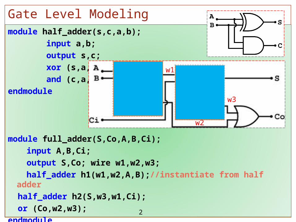
module half_adder(s,c,a,b);
input a,b;
output s,c;
xor (s,a,b);
and (c,a,b);
endmodule
module full_adder(S,Co,A,B,Ci);
input A,B,Ci;
output S,Co; wire w1,w2,w3;
half_adder h1(w1,w2,A,B);//instantiate from half adder
half_adder h2(S,w3,w1,Ci);
or (Co,w2,w3);
endmodule
Gate Level Modeling
2
w3
w1
w2
www.iiu.edu.pk Saturday, April 15, 2023
module four_bit_adder(Sum,Cout,A,B,Cin);
// I/O port declarations
output [3:0] Sum; output Cout;
input[3:0] A, B; input Cin;
wire c1, c2, c3; // Internal nets
// Instantiate four 1-bit full adders.
full_adder FA0(Sum[0], c1, A[0], B[0], Cin);
full_adder FA1(Sum[1], c2, A[1], B[1], c1);
full_adder FA2(Sum[2], c3, A[2], B[2], c2);
full_adder FA3(Sum[3], Cout, A[3], B[3], c3);
endmodule
4-Bit Full Adder instantiating from 1-bit full adder
3
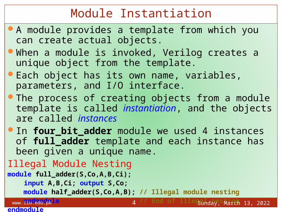
A module provides a template from which you can create actual objects.
When a module is invoked, Verilog creates a unique object from the template.
Each object has its own name, variables, parameters, and I/O interface.
The process of creating objects from a module template is called instantiation, and the objects are called instances
In four_bit_adder module we used 4 instances of full_adder template and each instance has been given a unique name.
Illegal Module Nestingmodule full_adder(S,Co,A,B,Ci);
input A,B,Ci; output S,Co; module half_adder(S,Co,A,B); // Illegal module nesting endmodule // End of Illegal nestingendmodule
Module Instantiation
Saturday, April 15, 2023www.iiu.edu.pk 4

www.iiu.edu.pk Saturday, April 15, 2023
Design Hierarchy
5
1-bit Full Adder
1-bit Full Adder
1-bit Full Adder
1-bit Full Adder
1-bit Full Adder
1-bit Full Adder
Half AdderHalf Adder OROR
ANDAND XORXOR
Four Bit Full AdderFour Bit Full Adder
1-bit Full Adder
1-bit Full Adder
Half AdderHalf Adder
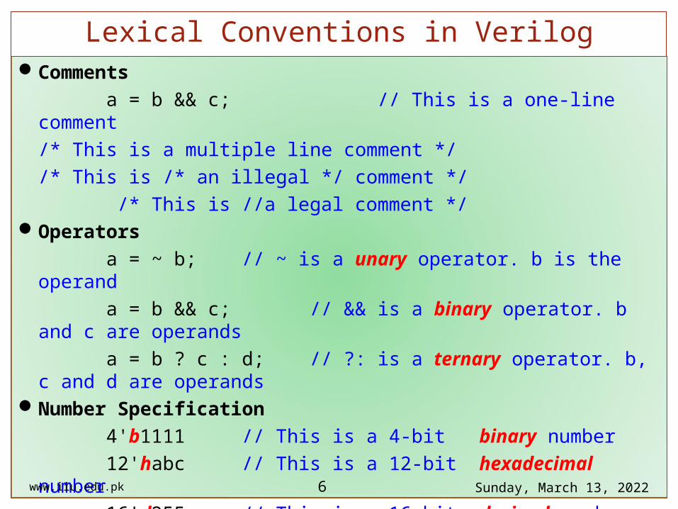
Comments
a = b && c; // This is a one-line comment
/* This is a multiple line comment */
/* This is /* an illegal */ comment */
/* This is //a legal comment */Operators
a = ~ b; // ~ is a unary operator. b is the operand
a = b && c; // && is a binary operator. b and c are operands
a = b ? c : d; // ?: is a ternary operator. b, c and d are operandsNumber Specification
4'b1111 // This is a 4-bit binary number
12'habc // This is a 12-bit hexadecimal number
16'd255 // This is a 16-bit decimal number.
9'O641 // This is a 12-bit octal number
// Uppercase letters (B,H,D,O) are also legal for number specification.
www.iiu.edu.pk Saturday, April 15, 2023
Lexical Conventions in Verilog
6
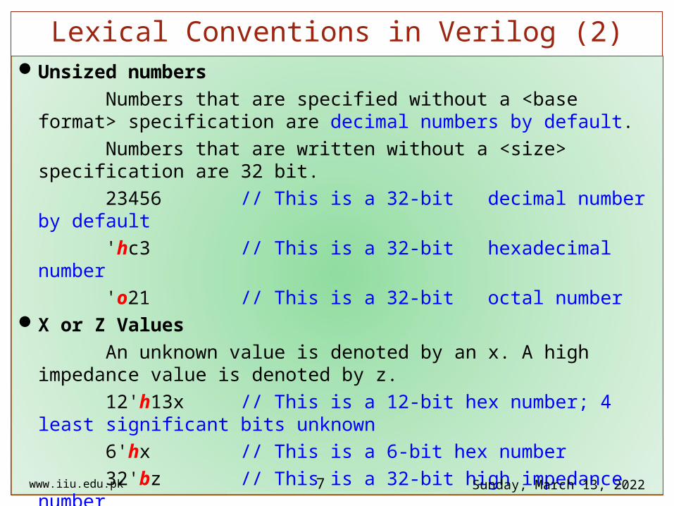
Unsized numbers
Numbers that are specified without a <base format> specification are decimal numbers by default.
Numbers that are written without a <size> specification are 32 bit.
23456 // This is a 32-bit decimal number by default
'hc3 // This is a 32-bit hexadecimal number
'o21 // This is a 32-bit octal numberX or Z Values
An unknown value is denoted by an x. A high impedance value is denoted by z.
12'h13x // This is a 12-bit hex number; 4 least significant bits unknown
6'hx // This is a 6-bit hex number
32'bz // This is a 32-bit high impedance number
An x or z sets four bits for a number in the hexadecimal base, three bits for a number in the octal base, and one bit for a number in the binary base.
If the most significant bit of a number is 0, x, or z, the number is automatically extended to fill the most significant bits, respectively, with 0, x, or z.
www.iiu.edu.pk Saturday, April 15, 2023
Lexical Conventions in Verilog (2)
7

This makes it easy to assign x or z to whole vector. If the most significant digit is 1, then it is also zero extended.
Negative numbers
-6'd3 // 6-bit negative number stored as 2's complement of 3
-6'sd3 // Used for performing signed integer math
4'd-2 // Illegal specification Underscore characters and question marks
An underscore character "_" is allowed anywhere in a number except the first character. Underscore characters are allowed only to improve readability of numbers and are ignored by Verilog.
A question mark "?" is the Verilog HDL alternative for z in the context of numbers.
12'b1111_0000_1010 // Use of underline characters for readability
4'b10?? // Equivalent of a 4'b10zz
www.iiu.edu.pk Saturday, April 15, 2023
Lexical Conventions in Verilog (3)
8
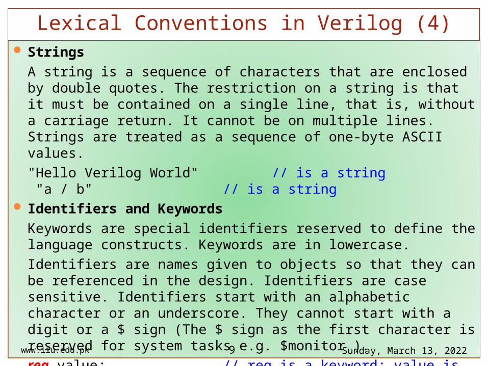
Strings
A string is a sequence of characters that are enclosed by double quotes. The restriction on a string is that it must be contained on a single line, that is, without a carriage return. It cannot be on multiple lines. Strings are treated as a sequence of one-byte ASCII values.
"Hello Verilog World" // is a string "a / b" // is a string
Identifiers and Keywords
Keywords are special identifiers reserved to define the language constructs. Keywords are in lowercase.
Identifiers are names given to objects so that they can be referenced in the design. Identifiers are case sensitive. Identifiers start with an alphabetic character or an underscore. They cannot start with a digit or a $ sign (The $ sign as the first character is reserved for system tasks e.g. $monitor ).
reg value; // reg is a keyword; value is an identifier
input clk; // input is a keyword, clk is an identifier
www.iiu.edu.pk Saturday, April 15, 2023
Lexical Conventions in Verilog (4)
9

Escaped Identifiers List of Keywords Escaped identifiers begin
with the backslash ( \ )
character and end with
whitespace (space, tab, or
newline). All characters between
backslash and whitespace
are processed literally. Neither the backslash nor the
terminating whitespace is
considered to be a part of the
identifier.
\a+b-c \**my_name**
www.iiu.edu.pk Saturday, April 15, 2023
Lexical Conventions in Verilog (5)
10
alwaysandassignattributebeginbufbufif0bufif1casecasexcasezcmosdeassigndefaultdefparamdisableedgeelseendendattributeendcaseendfunction
endmoduleendprimitiveendspecifyendtableendtaskeventforforceforeverforkfunctionhighz0highz1ififnoneinitialinoutinputintegerjoinmediummodule
largemacromodulenandnegedgenmosnornotnotif0notif1oroutputparameterpmosposedgeprimitivepull0pull1pulldownpulluprcmosrealrealtime
regreleaserepeatrnmosrpmosrtranrtranif0rtranif1scalaredsignedsmallspecifyspecparamstrengthstrong0strong1supply0supply1tabletasktimetran
tranif0tranif1tritri0tri1triandtriortriregunsignedvectoredwaitwandweak0weak1whilewireworxnorxor
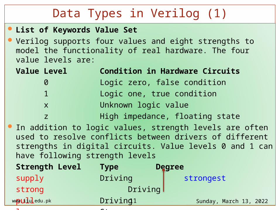
List of Keywords Value Set Verilog supports four values and eight strengths to model the functionality of real
hardware. The four value levels are:
Value Level Condition in Hardware Circuits
0 Logic zero, false condition
1 Logic one, true condition
x Unknown logic value
z High impedance, floating state In addition to logic values, strength levels are often used to resolve conflicts
between drivers of different strengths in digital circuits. Value levels 0 and 1 can have following strength levels
Strength Level Type Degree
supply Driving strongest
strong Driving
pull Driving
large Storagewww.iiu.edu.pk Saturday, April 15, 2023
Data Types in Verilog (1)
11

Strength Level Type Degree
weak Driving
medium Storage
small Storage
highz High Impedance weakest If two signals of unequal strengths are driven on a wire, the stronger signal
prevails. For example; if two signals of strength strong1 and weak0 contend, the result is resolved as a strong1.
If two signals of equal strengths are driven on a wire, the result is unknown. For Example; If two signals of strength strong1 and strong0 conflict, the result is
an x. Strength levels are particularly useful for accurate modeling of signal contention,
MOS devices, dynamic MOS, and other low-level devices. Only trireg nets can have storage strengths large, medium, and small.
www.iiu.edu.pk Saturday, April 15, 2023
Data Types in Verilog (2)
12
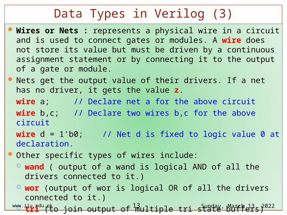
Wires or Nets : represents a physical wire in a circuit and is used to connect gates or modules. A wire does not store its value but must be driven by a continuous assignment statement or by connecting it to the output of a gate or module.
Nets get the output value of their drivers. If a net has no driver, it gets the value z.
wire a; // Declare net a for the above circuit
wire b,c; // Declare two wires b,c for the above circuit
wire d = 1'b0; // Net d is fixed to logic value 0 at declaration. Other specific types of wires include:
wand ( output of a wand is logical AND of all the drivers connected to it.) wor (output of wor is logical OR of all the drivers connected to it.) tri (to join output of multiple tri state buffers)
wire a,b; wand d; assign d = a; assign d = b; // d is logical and of a and b
www.iiu.edu.pk Saturday, April 15, 2023
Data Types in Verilog (3)
13

Registers: A reg is a Verilog variable type and does not necessarily imply a physical register. In multi-bit registers, data is stored as unsigned numbers and no sign extension is done for what the user might have thought were two’s complement numbers.
Unlike a net, a register does not need a driver. Values of registers can be changed anytime in a simulation by assigning a new value to the register.
The default value for a reg data type is x.
reg reset; // declare a variable reset that can hold its value
initial // this construct will be discussed later
begin
reset = 1'b1; // initialize reset to 1 to reset the digital circuit.
#100 reset = 1'b0; // after 100 time units reset is deasserted.
end Registers can also be declared as signed variables. Such registers can be used for
signed arithmetic for example.
reg signed [63:0] m; // 64 bit signed value integer i; // 32 bit signed value . www.iiu.edu.pk Saturday, April 15, 2023
Data Types in Verilog (4)
14
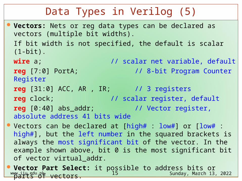
Vectors: Nets or reg data types can be declared as vectors (multiple bit widths).
If bit width is not specified, the default is scalar (1-bit).
wire a; // scalar net variable, default
reg [7:0] PortA; // 8-bit Program Counter Register
reg [31:0] ACC, AR , IR; // 3 registers
reg clock; // scalar register, default
reg [0:40] abs_addr; // Vector register, absolute address 41 bits wide
Vectors can be declared at [high# : low#] or [low# : high#], but the left number in the squared brackets is always the most significant bit of the vector. In the example shown above, bit 0 is the most significant bit of vector virtual_addr.
Vector Part Select: it possible to address bits or parts of vectors.
initial begin PortA[7] =1'b1; // bit # 7 of vector
AR[2:0]=3'b1zx; // Three least significant bits of Address Register,
// using AR[0:2] is illegal. the significant bit should
// always be on the left of a range specification
abs_addr[0:1] =2'b11; end // Two most significant bits of vector virtual_addrwww.iiu.edu.pk Saturday, April 15, 2023
Data Types in Verilog (5)
15
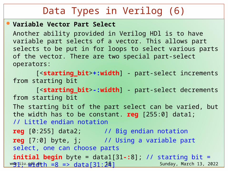
Variable Vector Part Select
Another ability provided in Verilog HDl is to have variable part selects of a vector. This allows part selects to be put in for loops to select various parts of the vector. There are two special part-select operators:
[<starting_bit>+:width] - part-select increments from starting bit
[<starting_bit>-:width] - part-select decrements from starting bit
The starting bit of the part select can be varied, but the width has to be constant. reg [255:0] data1; // Little endian notation
reg [0:255] data2; // Big endian notation
reg [7:0] byte, j; // Using a variable part select, one can choose parts
initial begin byte = data1[31-:8]; // starting bit = 31, width =8 => data[31:24]
byte = data1[24+:8]; // starting bit = 24, width =8 => data[31:24]
byte = data2[31-:8]; // starting bit = 31, width =8 => data[24:31]
byte = data2[24+:8]; end// starting bit = 24, width =8 => data[24:31]
// The starting bit can also be a variable. The width has to be constant. Therefore,
// one can use the variable part select in a loop to select all bytes of the vector.www.iiu.edu.pk Saturday, April 15, 2023
Data Types in Verilog (6)
16
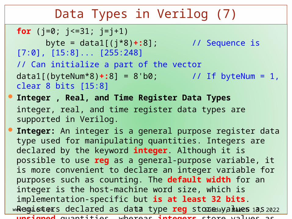
for (j=0; j<=31; j=j+1)
byte = data1[(j*8)+:8]; // Sequence is [7:0], [15:8]... [255:248]
// Can initialize a part of the vector
data1[(byteNum*8)+:8] = 8'b0; // If byteNum = 1, clear 8 bits [15:8] Integer , Real, and Time Register Data Types
integer, real, and time register data types are supported in Verilog. Integer: An integer is a general purpose register data type used for manipulating
quantities. Integers are declared by the keyword integer. Although it is possible to use reg as a general-purpose variable, it is more convenient to declare an integer variable for purposes such as counting. The default width for an integer is the host-machine word size, which is implementation-specific but is at least 32 bits. Registers declared as data type reg store values as unsigned quantities, whereas integers store values as signed quantities.
integer counter; // general purpose variable used as a counter.
initial counter = -1; // A negative one is stored in the counter
www.iiu.edu.pk Saturday, April 15, 2023
Data Types in Verilog (7)
17
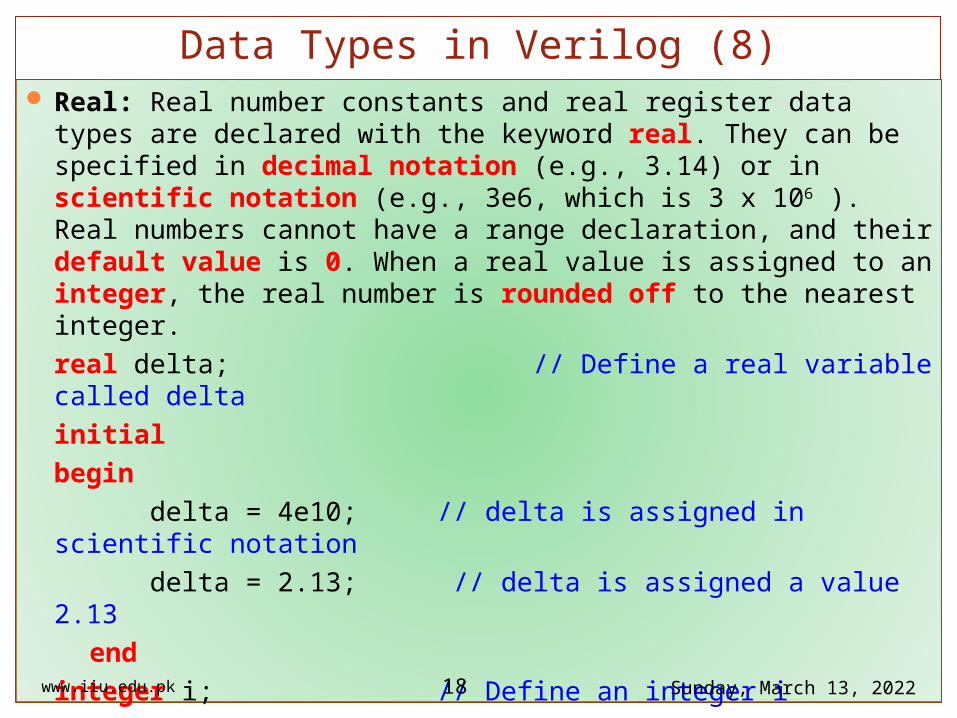
Real: Real number constants and real register data types are declared with the keyword real. They can be specified in decimal notation (e.g., 3.14) or in scientific notation (e.g., 3e6, which is 3 x 10⁶ ). Real numbers cannot have a range declaration, and their default value is 0. When a real value is assigned to an integer, the real number is rounded off to the nearest integer.
real delta; // Define a real variable called delta
initial
begin
delta = 4e10; // delta is assigned in scientific notation
delta = 2.13; // delta is assigned a value 2.13
end
integer i; // Define an integer i
initial
i = delta; // i gets the value 2 (rounded value of 2.13)
www.iiu.edu.pk Saturday, April 15, 2023
Data Types in Verilog (8)
18
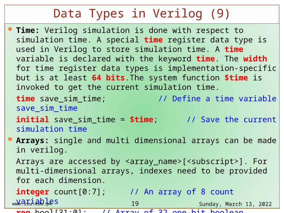
Time: Verilog simulation is done with respect to simulation time. A special time register data type is used in Verilog to store simulation time. A time variable is declared with the keyword time. The width for time register data types is implementation-specific but is at least 64 bits.The system function $time is invoked to get the current simulation time.
time save_sim_time; // Define a time variable save_sim_time
initial save_sim_time = $time; // Save the current simulation time Arrays: single and multi dimensional arrays can be made in verilog.
Arrays are accessed by <array_name>[<subscript>]. For multi-dimensional arrays, indexes need to be provided for each dimension.
integer count[0:7]; // An array of 8 count variables
reg bool[31:0]; // Array of 32 one-bit boolean register variables
time chk_point[1:100]; // Array of 100 time checkpoint variables
reg [4:0] port_id[0:7]; // Array of 8 port_ids; each port_id is 5 bits wide
integer matrix[4:0][0:255]; // Two dimensional array of integers
www.iiu.edu.pk Saturday, April 15, 2023
Data Types in Verilog (9)
19
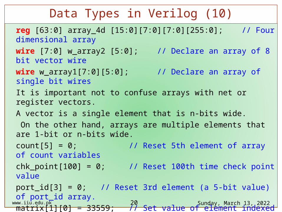
reg [63:0] array_4d [15:0][7:0][7:0][255:0]; // Four dimensional array
wire [7:0] w_array2 [5:0]; // Declare an array of 8 bit vector wire
wire w_array1[7:0][5:0]; // Declare an array of single bit wires
It is important not to confuse arrays with net or register vectors.
A vector is a single element that is n-bits wide.
On the other hand, arrays are multiple elements that are 1-bit or n-bits wide.
count[5] = 0; // Reset 5th element of array of count variables
chk_point[100] = 0; // Reset 100th time check point value
port_id[3] = 0; // Reset 3rd element (a 5-bit value) of port_id array.
matrix[1][0] = 33559; // Set value of element indexed by [1][0] to 33559
array_4d[0][0][0][0][15:0] = 0; // Clear bits 15:0 of the register
// accessed by indices [0][0][0][0]
port_id = 0; // Illegal syntax - Attempt to
www.iiu.edu.pk Saturday, April 15, 2023
Data Types in Verilog (10)
20
write the entire array
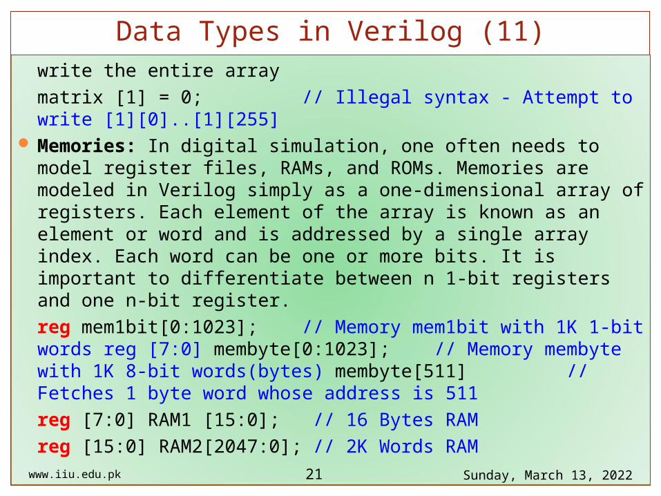
matrix [1] = 0; // Illegal syntax - Attempt to write [1][0]..[1][255] Memories: In digital simulation, one often needs to model register files, RAMs,
and ROMs. Memories are modeled in Verilog simply as a one-dimensional array of registers. Each element of the array is known as an element or word and is addressed by a single array index. Each word can be one or more bits. It is important to differentiate between n 1-bit registers and one n-bit register.
reg mem1bit[0:1023]; // Memory mem1bit with 1K 1-bit words reg [7:0] membyte[0:1023]; // Memory membyte with 1K 8-bit words(bytes) membyte[511] // Fetches 1 byte word whose address is 511
reg [7:0] RAM1 [15:0]; // 16 Bytes RAM
reg [15:0] RAM2[2047:0]; // 2K Words RAM
www.iiu.edu.pk Saturday, April 15, 2023
Data Types in Verilog (11)
21