FP9350 User Installation Manual A5-V2LR - Aerpro
48
VE FACIA KIT USER/INSTALL MANUAL FP9350
Transcript of FP9350 User Installation Manual A5-V2LR - Aerpro

VEFACIA KIT
USER/INSTALLMANUAL
FP9350

Product overview
The Aerpro FP9350 VE Facia Installation Kit is Australian designed and engineered and has been made for fitting a double DIN aftermarket radio, CD or DVD player to the original double DIN enclosure. It suits VE series 1 single climate models by upgrading heater valve heating & cooling to full digital climate control. Compatible models for this kit are the Omega, V, Lumina, International, SV6, SS and 60th Anniversary edition. See pictures below as examples.
2
Inclusions
1x ABS Plastic facia1x H-VAC controller with built in steering wheel control module1x Universal patch lead 1x Antenna adapter1x Mounting kit1x Remote temperature sensor
3
1x ABS Plastic facia1x H-VAC controller with built in steering wheel control module1x Universal patch lead 1x Antenna adapter1x Mounting kit1x Remote temperature sensor
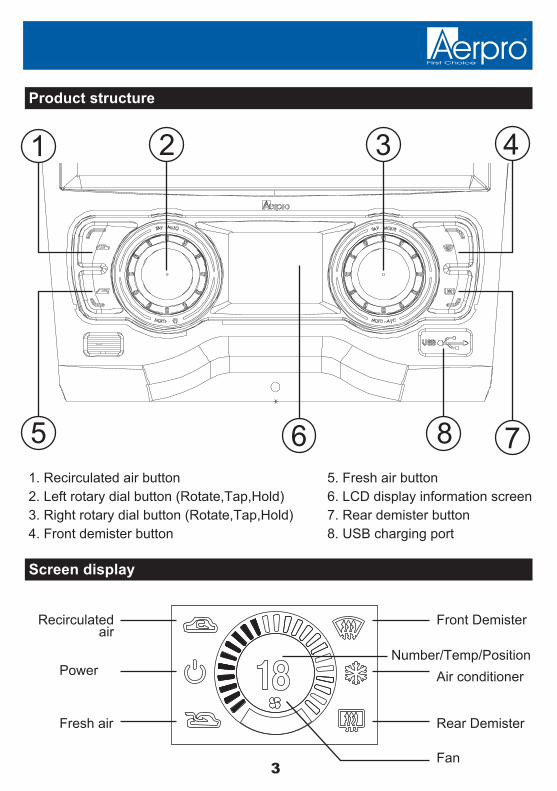
Product structure
Screen display
1. Recirculated air button2. Left rotary dial button (Rotate,Tap,Hold) 3. Right rotary dial button (Rotate,Tap,Hold)4. Front demister button
5. Fresh air button6. LCD display information screen7. Rear demister button8. USB charging port
1 2 3 4
5 6 8 7
Recirculatedair
Front Demister
Fan
Number/Temp/Position
Rear Demister
Air conditionerPower
Fresh air
4
5. Fresh air button6. LCD display information screen7. Rear demister button8. USB charging port
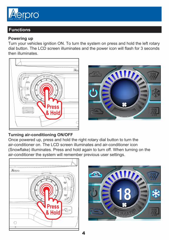
Functions
Powering upTurn your vehicles ignition ON. To turn the system on press and hold the left rotary dial button. The LCD screen illuminates and the power icon will flash for 3 seconds then illuminates.
Turning air-conditioning ON/OFFOnce powered up, press and hold the right rotary dial button to turn theair-conditioner on. The LCD screen illuminates and air-conditioner icon (Snowflake) illuminates. Press and hold again to turn off. When turning on the air-conditioner the system will remember previous user settings.
18
Press& Hold
Press& Hold

5
Positioning
To select different air positions in the vehicle tap the right rotary button. Positions are for the Head/Feet, Chest, Chest/Feet and Feet (See icons below).
Tap
6
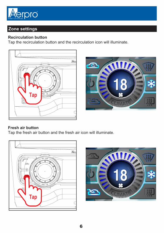
Zone settings
Recirculation buttonTap the recirculation button and the recirculation icon will illuminate.
Tap18
Fresh air buttonTap the fresh air button and the fresh air icon will illuminate.
18Tap

7
Zone settings
Front demister buttonTap the front demister button and the front demister icon will illuminate. The air-conditioiner will automatically turn on to aid demisting. The air-conditioner icon will also illuminate.
18
Rear demister buttonTap the rear demister button and the rear demister icon will illuminate.
18
Tap
Tap

8
Rotary dial functions
Fan speedTurn the left rotary dial to the right and left to increase and decrease the fan speed.This is represented by the illuminated blue bars.
18
18Rotate
Rotate
Air-conditioner temperatureTurn the right rotary dial to the left and right to lower and/or rise the air-conditioner temperature. This is a numeric value of 15 the lowest to 29 the highest. Turning the dial too fast may result in the command signal not registering.

9
Functions
Automatic climate controlTo activate auto climate mode, tap the left hand rotary dial and then set the target temperature by rotating the right hand rotary dial to the desired level. The fan speed, the vent temperature and the air flow direction is fully automatic and will adjust itself based on what it needs to get to the required level. NOTE: If you change the vent mode (air flow direction) or fan speed during auto climate operation the system will exit climate mode. When in climate mode the words Auto Climate at the bottom of the screen is illuminated and the temperature display has a degree (°) sign next to the numeric value.
o
18AUTO
RotateTap

10
Settings for clock/date
Changing the time /date of the vehicles existing clock display
1. Make sure the unit is turned off.
2. Press and hold the right rotary button for 5 seconds to enter the settings for the vehicles existing clock & date.
The existing display in the vehicle will highlight & flash for each value.
3. Turn the right rotary button to the left or right to change each value.
4. Press & hold the right rotary button to apply the value and progress through each setting.
5. Continue through each setting to exit.
Press& Hold
Rotate

11
Resetting the system
In the case of the system locking up or not functioning correctly, the unit can be reset to factory settings.
Press & hold both left & right rotary knobs at the same time.
Press& Hold
Press& Hold
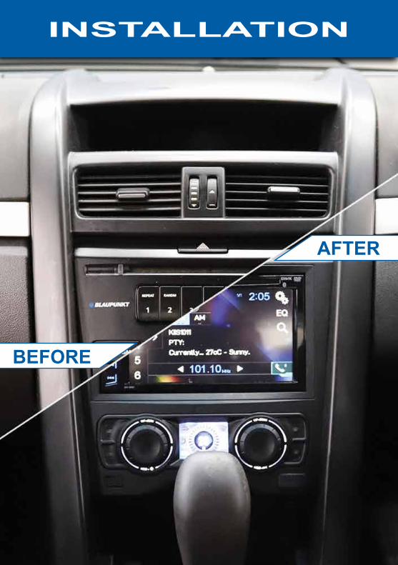
BEFORE
AFTER
INSTALLATION
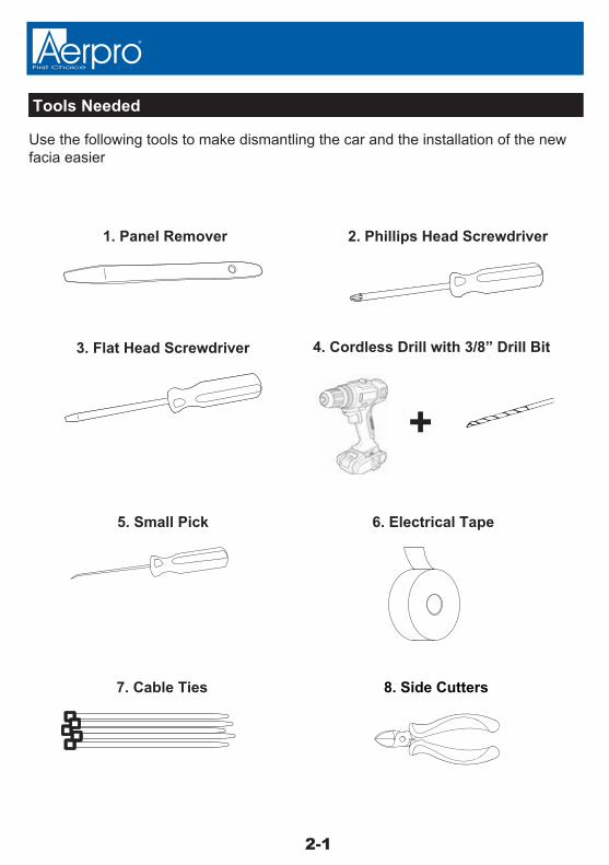
1. Panel Remover 2. Phillips Head Screwdriver
3. Flat Head Screwdriver 4. Cordless Drill with 3/8” Drill Bit
5. Small Pick 6. Electrical Tape
7. Cable Ties
+
8. Side Cutters
Use the following tools to make dismantling the car and the installation of the new facia easier
Tools Needed
2-1

Remove left side dash trimInsert a panel remover and lever towards you
Remove left side dash trimPlace trim aside safely until trim reassembly
Dash Disassembly
2-2

Remove boot button trimInsert a panel remover or pick and unclip the boot button trim
Remove boot button trimPlace trim aside safely until trim reassembly
2-3
Dash Disassembly

Remove left side screw cover trimInsert a panel remover or pick and unclip the left side screw cover
Remove left side screw cover trimPlace trim aside safely until trim reassembly
2-4
Dash Disassembly

Remove left side dash end trimInsert a panel remover and lever outwards to remove trim
Remove left side dash end trimPlace trim aside safely until trim reassembly
Functions and settings
2-5

Remove left side lower dash trimInsert a panel remover and lever the trim downwards to release
Remove left side lower dash trimPlace trim aside safely until trim reassembly
2-6
Dash Disassembly

Remove glove boxThere are 2x screws to remove at the base of the glove box as indicated
2-7
Dash Disassembly
Remove glove boxUsing a Phillips head No.2 screwdriver to remove the indicated screws as shown on the next page
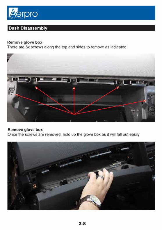
Remove glove boxThere are 5x screws along the top and sides to remove as indicated
Remove glove boxOnce the screws are removed, hold up the glove box as it will fall out easily
2-8
Dash Disassembly
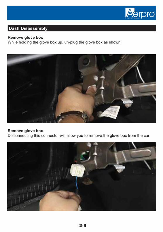
Remove glove boxWhile holding the glove box up, un-plug the glove box as shown
Remove glove boxDisconnecting this connector will allow you to remove the glove box from the car
2-9
Dash Disassembly
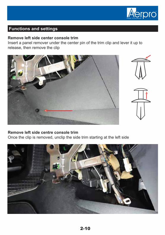
Remove left side center console trimInsert a panel remover under the center pin of the trim clip and lever it up to release, then remove the clip
Remove left side centre console trimOnce the clip is removed, unclip the side trim starting at the left side
Functions and settings
2-10
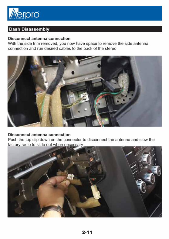
Disconnect antenna connectionWith the side trim removed, you now have space to remove the side antenna connection and run desired cables to the back of the stereo
Disconnect antenna connectionPush the top clip down on the connector to disconnect the antenna and slow the factory radio to slide out when necessary
2-11
Dash Disassembly

Take pictures of side trim removal
Remove right side dash trimInsert a panel remover and lever towards you
Remove right side dash trimPlace trim aside safely until trim reassembly
2-12
Dash Disassembly

Remove right side dash end trimInsert a panel remover and lever outwards to remove trim
Remove right side dash end trimPlace trim aside safely until trim reassembly
2-13
Dash Disassembly

Remove under steering wheel coverInsert a panel remover and lever downwards to remove trim remembering to do the same thing on the left side of the steering wheel as well
Remove under steering wheel coverwhile unclipping, be sure to hold up the panel and not let it drop to protect the headlight switch connection
2-14
Dash Disassembly
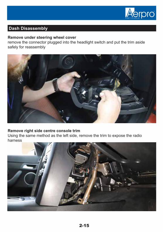
Remove under steering wheel coverremove the connector plugged into the headlight switch and put the trim aside safely for reassembly
Remove right side centre console trimUsing the same method as the left side, remove the trim to expose the radio harness
2-15
Dash Disassembly

EXAMPLE
Unplug the radio connectorTo remove the connector, pinch the top clip and pull the handle backwards to release the connector. *NOTE* Remove CD’s before unplugging stereo
Unplug the radio connectorOnce the connector has been unplugged, the radio is free to be removed
2-16
Dash Disassembly

Remove the factory radio face panelThe factory face panel is held on with 4x clips. Start by unclipping the bottom using your hands or panel remover. Take care when unclipping to not damage the face
Remove the factory radio face panelYou will feel the face panel come lose when the clips have released
2-17
Dash Disassembly

Remove the factory radio face panelYou may have to pivot the face panel back and forth to release the top clips, or use a panel remover to try release the top clips
Remove the factory radio face panelThere are no cables to disconnect, so you are free remove the factory face panel
2-18
Dash Disassembly

Remove the factory radioThere are 4x screws to remove as indicated below
Remove the factory radioUse and phillips head no.2 screwdriver to remove the screws
2-19
Dash Disassembly
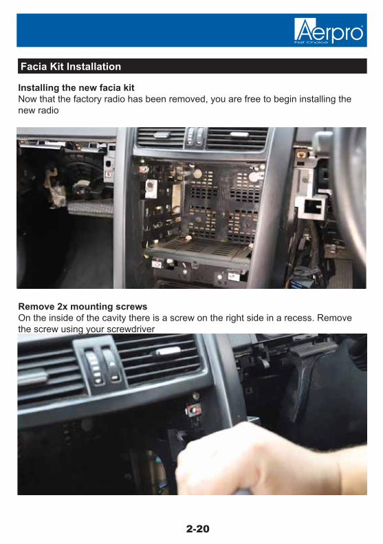
Installing the new facia kitNow that the factory radio has been removed, you are free to begin installing the new radio
Remove 2x mounting screwsOn the inside of the cavity there is a screw on the right side in a recess. Remove the screw using your screwdriver
Facia Kit Installation
2-20

Remove 2x mounting screwsThere is also a screw on the opposite left side, remove this screw as well and keep the screws handy for re-installation
Installing the temperature sensorTo install the temp sensor, you will need cable ties
2-21
Facia Kit Installation
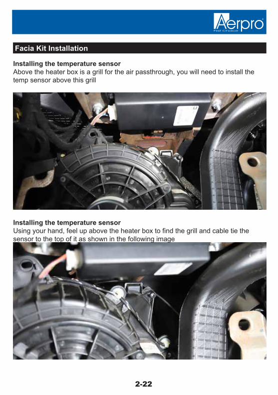
Installing the temperature sensorAbove the heater box is a grill for the air passthrough, you will need to install the temp sensor above this grill
Installing the temperature sensorUsing your hand, feel up above the heater box to find the grill and cable tie the sensor to the top of it as shown in the following image
2-22
Facia Kit Installation

Installing the temperature sensorRun the sensor above the grill and cable tie into place, ensuring the sensor does not fall into the grill where there are moving parts
Preparing the new facia kitTo mount the facia kit, plug the main power harness for the facia in
*Heater box removed from car and shown from the rear*
2-23
Facia Kit Installation

Preparing the new facia kitIf your aftermarket stereo is equipped with a steering wheel remote input, plug the steering wheel patch lead in the fasia as well
Preparing the new facia kitOnce the connectors are plugged in, ensure the steering wheel control patch lead is configured for your aftermarket stereo
2-24
Facia Kit Installation
AlpineCut Green Link
JVCCut Green & Purple Link
ClarionCut Purple Link
PIONEER, LG & SONYNo cutting required
Philips, NakamichiCut Orange & Purple Wire
KenwoodCut Orange & Green Wire
PanasonicCut Orange Wire
ZenecCut all 3 wires, solder Orange and Green together as shown
use 3.5mm Jack for these Head-units
APUNIPL & APUNIPL2Universal C type Patch Lead
use Key 1 Bullet terminal for these Head-units
For best results or to reset the control module with a new Brand. Please make modifications to the Patch lead first, before connecting to the steering wheel control module and before powering the module up.
use Key 1, Key 2 and GND Bullet terminals for Self Learn Head-units
Self Learn Head-unitsNo cutting required
APUNIPL2 only

Mounting the new faciaRun the aftermarket wiring harness through the hole to the right where the factory connector is located
Mounting the new faciaRun the temp sensor neatly to behind the radio and plug it into the facia
2-25
Facia Kit Installation

Mounting the new faciaConnect the supplied antenna adapter to the factory antenna connector
Mounting the new faciaPush the facia into the dash cavity so the locator's left and right clip into place
2-26
Facia Kit Installation

Mounting the new faciaEnsure the facia is sitting correctly so the holes on the facia line up with the vehicle mounting holes
Mounting the new faciaUsing the screws which were removed on pages 20/21 mount the facia to the mounting points in the dash cavity
2-27
Facia Kit Installation

Mounting the new faciaUsing the screws which were removed on pages 20/21 mount the facia to the mounting points in the dash cavity
Mounting the new faciaFor extra security, there is a 3rd mounting point at the base of the facia, using a drill, per-drill a hole in the dash so a screw can be inserted
2-28
Facia Kit Installation
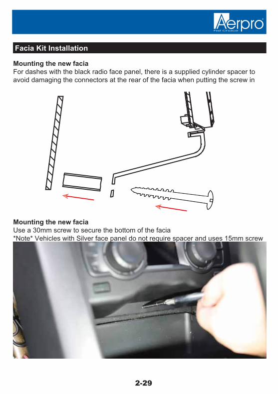
Mounting the new faciaFor dashes with the black radio face panel, there is a supplied cylinder spacer to avoid damaging the connectors at the rear of the facia when putting the screw in
Mounting the new faciaUse a 30mm screw to secure the bottom of the facia*Note* Vehicles with Silver face panel do not require spacer and uses 15mm screw
2-29
Facia Kit Installation

Installing the mounting cageWhen inserting the mounting cage, run all cables out of the front to make connecting the aftermarket stereo easier
Installing the mounting cageUse a flat head screwdriver to bend the tabs on the inside of the cage and secure the cage to the facia
2-30
Facia Kit Installation
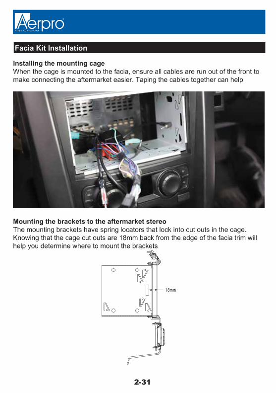
Installing the mounting cageWhen the cage is mounted to the facia, ensure all cables are run out of the front to make connecting the aftermarket easier. Taping the cables together can help
Mounting the brackets to the aftermarket stereoThe mounting brackets have spring locators that lock into cut outs in the cage. Knowing that the cage cut outs are 18mm back from the edge of the facia trim will help you determine where to mount the brackets
2-31
Facia Kit Installation

Mounting the brackets to the aftermarket stereoAlign the bracket on the stereo and then set the depth using the slider clip depending on how you want the stereo to look in the facia
Testing the system before completing installationOnce the brackets are mounted, slide the unit into the cage, but not the whole way.Connect the quadlock connectors together and turn the key to ‘Ignition’
2-32
Facia Kit Installation

Completing installationOnce fully powered, check the functionality of the stereo and the facia kit.If all is functioning how it should, you are free to complete the installation
Completing installationTurn off the car and push the stereo into the cage until it clicks into place
2-33
Facia Kit Installation
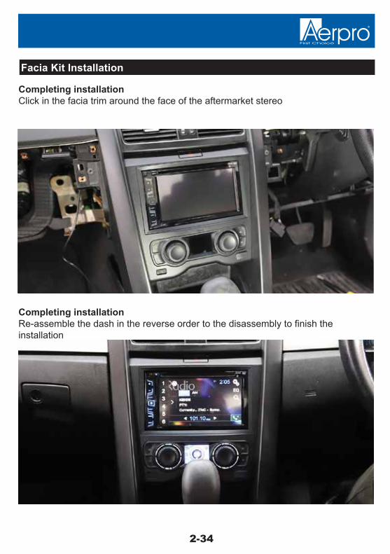
Completing installationClick in the facia trim around the face of the aftermarket stereo
Completing installationRe-assemble the dash in the reverse order to the disassembly to finish the installation
2-34
Facia Kit Installation

2-35
Installer Notes
2-35
Technical assistanceIf you need assistance setting up or using your Aerpro product now or in the future, call Aerpro Support. Australia
TEL: 03 – 8587 8898
FAX: 03 – 8587 8866
Mon-Fri 9am – 5pm AEST
Please retain this user guide for future reference.
If you would like to download a digital copy of this manual, or other Aerpro manuals/software, please visit the http://aerpro.com website and click on ‘Firmware & Manuals” for information on where to find the manuals/software.
This manual is considered correct at time of printing but is subject to change.For latest manuals and updates refer to the website.
Copyright © 2017 by TDJ AustraliaAll rights reserved. No part of this publication may be reproduced, distributed, or transmitted in any form or by any means, including photocopying, recording, copying or other electronic or mechanical methods, without the prior written permission of the author.