Fox Thermal Instruments, Inc. · Fox Thermal Instruments, Inc. ... Specifications Page 91 b. ......
100
106012 Rev. G Model FT1 Fox Thermal Instruments, Inc. www.foxthermalinstruments.com | 399 Reservation Road Marina, CA. 93933 THERMAL MASS FLOW METER & TEMPERATURE TRANSMITTER
Transcript of Fox Thermal Instruments, Inc. · Fox Thermal Instruments, Inc. ... Specifications Page 91 b. ......

106012 Rev. G
Model FT1
Fox Thermal Instruments, Inc.
www.foxthermalinstruments.com | 399 Reservation Road Marina, CA. 93933
THERMAL MASS FLOW METER & TEMPERATURE TRANSMITTER

F O X I S I S O 9 0 0 1 C E R T I F I E D
Fox FT1 Manuals:• Fox FT1 View™ Manual
All Fox Manuals and software available in English only.
2
Model FT1D
ISC
LAIM
ER
Notice
This publication must be read in its entirety before performing any operation. Failureto understand and follow these instructions could result in serious personal injury
and/or damage to the equipment. Should this equipment require repair or adjustmentbeyond the procedures given herein, contact the factory at:
FOX THERMAL INSTRUMENTS, INC.399 RESERVATION ROAD
MARINA, CA 93933TELEPHONE: 831-384-4300
FAX: 831-337-5787EMAIL: [email protected]
Download Technical Data Sheets from our website:www.foxthermalinstruments.com
Fox Thermal Instruments believes that the information provided herein is accurate; however, be advised that the information contained herein is NOT a guarantee for satisfactory results. Specifically, this information is neither a warranty nor
guarantee, expressed or implied, regarding performance, merchantability, fitness, or any other matter with respect to the products; nor recommendation for the use
of the product/process information in conflict with any patent. Please note that Fox Thermal Instruments, Inc. reserves the right to change and/or improve the product
design and specification without notice.

3
Model FT1TAB
LE O
F C
ON
TEN
TS
Table Of Contents
1. Introduction Page 4
a. Menu Trees Page 4
b. Quick Start Guide Page 12
2. Installation (Mechanical) Page 16
a. Installation Depth Page 18
b. Orientation of Flowmeter Page 19
c. Rotating the Probe/Enclosure Page 19
d. Changing the Orientation of the Display Page 27
e. Mounting Instructions Page 21
3. Wiring (Electrical) Page 26
a. General Wiring Page 28
b. Input Power Page 28
c. Signal Wiring Page 29
d. Pulse/Alarm Wiring (optional feature) Page 31
e. RS485 Wiring: Modbus RTU or BACnet MS/TP (optional feature) Page 33
f. HART wiring Page 34
4. Operation (Standard Operation) Page 36
a. Start Up Page 36
b. Programming Page 38
c. Zero CAL-CHECK® Page 54
d. Gas-SelectX® Page 58
5. Communication Protocols Page 63
a. RS485 Modbus RTU Page 63
b. BACnet MS/TP Page 71
c. HART Page 75
6. Maintenance Page 80
a. Precautions Page 80
b. General Page 81
c. Troubleshooting Page 86
7. Appendices Page 91
a. Specifications Page 91
b. Agency Approvals Page 93
c. Dimensions Page 94
d. Warranty Page 95
e. Returning your meter Page 97
8. Glossary of Terms and Abbreviations Page 98
9. Index Page 99
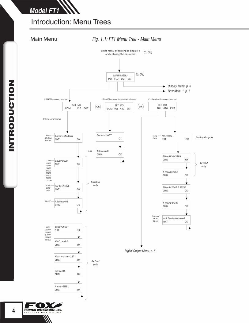
MAIN MENUI/O FLO DSP EXIT
SET I/OCOM 420 EXIT
Comm=ModbusNXT OK
NoneModbusBACnet
mA=FlowNXT OK
20 mACnt=3265CHG OK
4 mACnt=367 CHG OK
20 mA=2345.6 SCFMCHG OK
4 mA=0 SCFMCHG OK
TempFlow Analog Outputs
Baud=9600NXT OK
Parity=NONENXT OK
Address=02CHG OK
Modbus only
120024004800960019200384005760076800115200
NONEODDEVEN
01‐247
Enter menu by scolling to display 4 and entering the password
mA Fault=Not usedNXT OK
Not used3.6 mA21 mA
Baud=9600NXT OK
960019200384005760076800115200
MAC_add=3CHG OK
Max_master=127CHG OK
ID=12345CHG OK
Name=SITE1CHG OK
BACnet only
SET I/O PUL 420 EXIT
If RS485 hardware detected
Communication
OR
Level 2 only
OR SET I/OCOM PUL 420 EXIT
Comm=HART OK
Address=0CHG OK
If pulse/alarm hardware detectedIf HART hardware detected/with license
0‐63
(p. 38)
(p. 39)
Display Menu, p. 8Flow Menu 1, p. 6
Digital Output Menu, p. 5
4
Model FT1D
ISC
LAIM
ER
4
INTR
OD
UC
TIO
N
Fig. 1.1: FT1 Menu Tree - Main Menu Main Menu
Introduction: Menu Trees
Digital Output
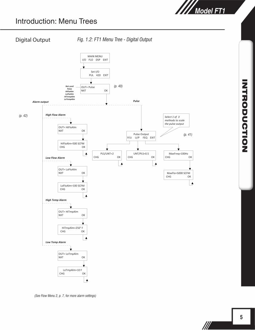
OUT= PulseNXT OK
Not usedPulse
HiFloAlmLoFloAlm
HiTempAlmLoTempAlm
Pulse OutputP/U U/P FEQ EXIT
PLS/UNT=2CHG OK
UNT/PLS=0.5CHG OK
MaxFreq=100HzCHG OK
MaxFlo=5000 SCFMCHG OK
HiFloAlm=500 SCFMCHG OK
LoFloAlm=100 SCFMCHG OK
HiTmpAlm=250° FCHG OK
LoTmpAlm=10 FCHG OK
High Flow Alarm
Low Flow Alarm
High Temp Alarm
Low Temp Alarm
Select 1 of 3 methods to scale the pulse output
Pulse
OUT= HiFloAlmNXT OK
OUT= LoFloAlmNXT OK
OUT= HiTmpAlmNXT OK
OUT= LoTmpAlmNXT OK
Set I/O PUL 420 EXIT
Alarm output
MAIN MENUI/O FLO DSP EXIT
(p. 40)
(p. 42)
(See Flow Menu 2, p. 7, for more alarm settings)
(p. 41)
5
Model FT1IN
TR
OD
UC
TIO
N
Fig. 1.2: FT1 Menu Tree - Digital Output
Introduction: Menu Trees
Digital Output

FLOW MENU 1DGN UNT FM2 EXIT
DIAGNOSTICSIM ZRO EXIT
FloSim=0 SCFMCHG OK
TmpSim=0 ° FCHG OK
ENABLE SIM?YES NO
FLO UNT=SCFMNXT OK
SCFMSCFHNM3/HNM3/MKG/HKG/MKG/SLBS/HLBS/MLBS/SNLPHNLPM
MMSCFDLBS/DSLPMNLPSMSCFDSM3/HMT/HNM3/D
MMSCFMMCFDSCFD
SM3/MSM3/D
TMP UNT=° FNXT OK
Deg FDeg C
TmpRef=60 °FCHG OK
PRES UNT=PsiaNXT OK
PresRef=14.73CHG OK
mmHGPsiabara
STPSimulate Flow?YES NO
Simulate Temp?YES NO
DNS=1.2323 kg/m3 OK
MAIN MENUI/O FLO DSP EXIT
(p. 52) (p. 46)
Flow Menu 2 Menu, p. 7
Zero CAL-CHECK® Menu, p. 9
6
Model FT1D
ISC
LAIM
ER
6
INTR
OD
UC
TIO
N
Fig. 1.3: FT1 Menu Tree - Flow Menu 1Flow Menu 1
Introduction: Menu Trees
Flow Menu 2

FLOW MENU 2GAS SPC PRM EXIT
K fact = 0%CHG OK
RESET CRC?YES NO
Cutoff=12.5 SCFMCHG OK
Pipe_id=4.026 InCHG OK
Filter=0.8 SecCHG OK
Parameters
Flow cutoff in selected units
Pipe id in inches or mm
Flow Filter in secondsMin = 0.8, max = 10
HiFloAlm=0 SCFMCHG OK
LoFloAlm=0 SCFMCHG OK
HiTmpAlm=0 SCFMCHG OK
LoTmpAlm=0 SCFMCHG OK
These alarms can be used without the digital output assigned to the alarm.If that is the case, the alarm status will only be shown on the display, through serial communication or FT1 View.If the digital output is assigned to an alarm, changing the value here will change that setting.
Level 2
RESTORE DATABASE?YES NO
SET NRT?YES NO
ARE YOU SURE?YES NO
TOT RST DISABLED OK
This message will show for 3 seconds before returning to the Flow Parameter 2 Menu.
WARNING: Once the non‐resettable totalizer is activated, it cannot be undone.
MAIN MENUI/O FLO DSP EXIT
FLOW MENU 1DGN UNT FM2 EXIT
(p. 50)
(p. 48)
(p. 49)
Gas-SelectX® Menu, p. 10
7
Model FT1IN
TR
OD
UC
TIO
N
Fig. 1.4: FT1 Menu Tree - Flow Menu 2
Introduction: Menu Trees
Flow Menu 2

DISPLAY/PASSWORDDSP PSW EXIT
DSP1L1=FLo rateNXT OK
FLo rateTotalElpsTempAlarm
DSP1L2=TotalNXT OK
DSP2L1=tempNXT OK
DSP2L2=ElpsNXT OK
ALTERNATE=OffNXT OK
OnOff
PASSWD=1234CHG OK
FLo rateTotalElpsTempAlarm
FLo rateTotalElpsTempAlarm
FLo rateTotalElpsTempAlarm
When alternate "ON", flashes between the 2 displays
Display 1 Line 1
Display 2 Line 1
Display 2 Line 2
MAIN MENUI/O FLO DSP EXIT
Display 1 Line 2
(p. 45)(p. 43)
8
Model FT1D
ISC
LAIM
ER
8
INTR
OD
UC
TIO
N
Fig. 1.5: FT1 Menu Tree - Display Menu
Note: All readings updated every second• Flo Rate = Flow rate of process gas• Total = Total flow of process gas• Elps = Elapsed time since reset of flow total• Temp = Temperature of process gas• Alarm = Notification of errors; diagnostic errors
Introduction: Menu Trees
Display Menu
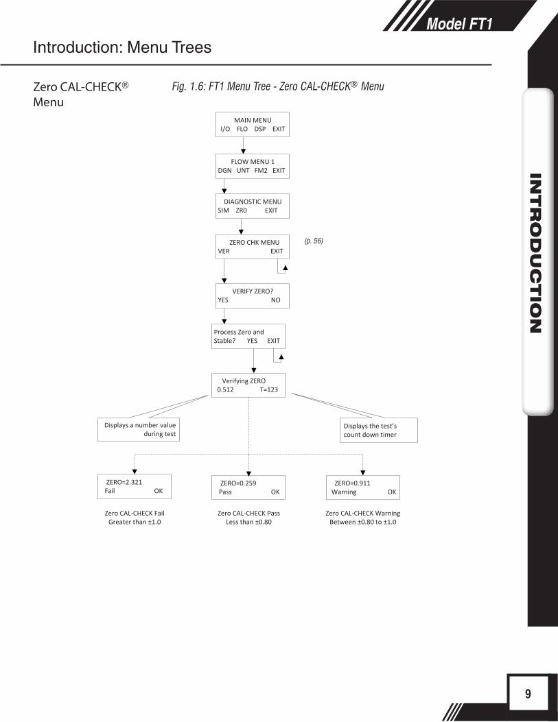
DIAGNOSTIC MENUSIM ZR0 EXIT
ZERO CHK MENUVER EXIT
Process Zero andStable? YES EXIT
Verifying ZERO 0.512 T=123
ZERO=0.259 Pass OK
Displays the test’s count down timer
Displays a number value during test
VERIFY ZERO?YES NO
ZERO=0.911 Warning OK
ZERO=2.321 Fail OK
FLOW MENU 1DGN UNT FM2 EXIT
MAIN MENUI/O FLO DSP EXIT
Zero CAL‐CHECK Fail Greater than ±1.0
Zero CAL‐CHECK Pass Less than ±0.80
Zero CAL‐CHECK Warning Between ±0.80 to ±1.0
(p. 56)
9
Model FT1IN
TR
OD
UC
TIO
N
Fig. 1.6: FT1 Menu Tree - Zero CAL-CHECK® Menu
Introduction: Menu Trees
Zero CAL-CHECK® Menu

FLOW MENU 2GAS SPC PRM EXIT
Propane = 0 %UP DN OK
GAS=%MixNXT OK
MethaneCO2NitrogenAirNatural GasArgonPropaneHeliumOxygenButaneHydrogenGas Mix
Oxygen = 0 %UP DN OK
Gas Mix (100%) OK
CO2 = 30 %UP DN OK
Shows only if gas mix does not equal 100%. Pressing OK returns to gas entry.
Air = 0 %UP DN OK
Argon = 0 %UP DN OK
MAIN MENUI/O FLO DSP EXIT
FLOW MENU 1DGN UNT FM2 EXIT
Err: Mix=(110%) OK
Err: Max 3 gas OK
Methane = 65 %UP DN OK
Hydrogen = 0 %UP DN OK
Butane = 0 %UP DN OK
Nitrogen = 5 %UP DN OK
Shows only if no error is detected. Pressing OK allows exit to menu.
Shows only if too many gases are selected. Only three (3) gases are allowed. Pressing OK returns to gas entry.
Select up to three gases for Gas Mix. Be sure mixture equals 100%.
OR OR
Helium = 0 %UP DN OK
(p. 58)
10
Model FT1D
ISC
LAIM
ER
10
INTR
OD
UC
TIO
N
Introduction: Menu Trees
Fig. 1.7: FT1 Menu Tree - Gas-SelectX® MenuGas-SelectX® Menu
The most recent list of available gases can be found on the Fox website:www.foxthermalinstruments.com
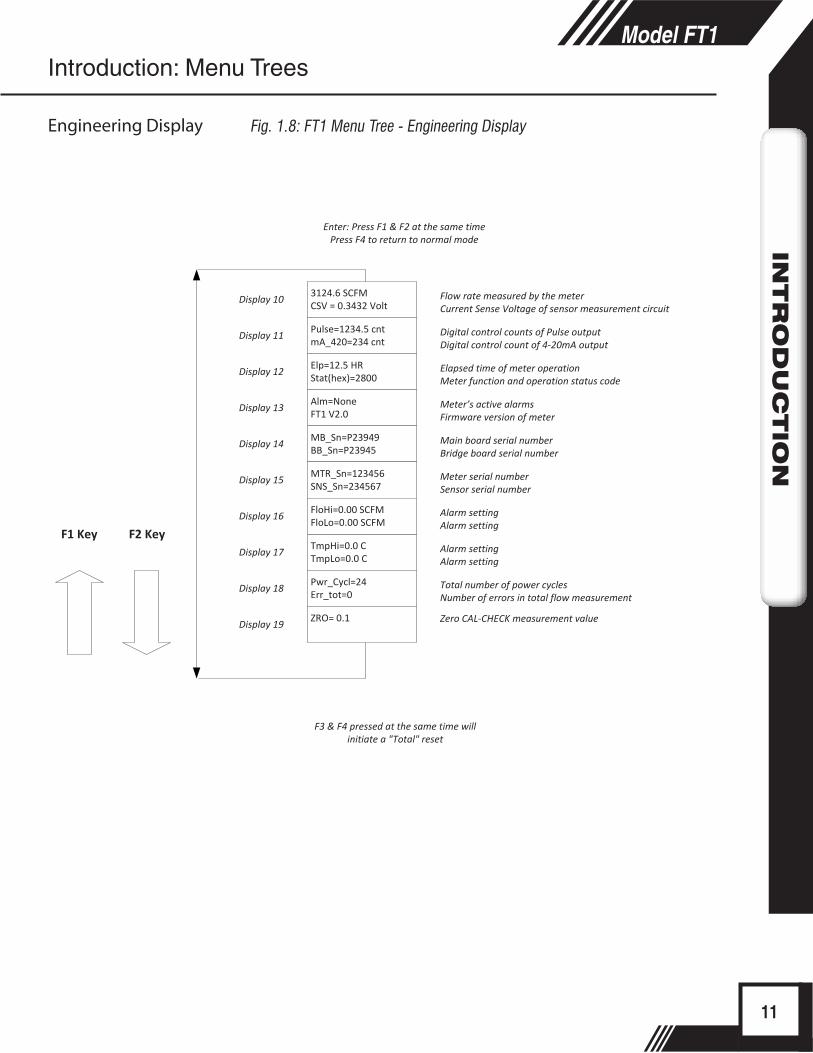
3124.6 SCFMCSV = 0.3432 Volt
Enter: Press F1 & F2 at the same timePress F4 to return to normal mode
Display 10
Display 11
Display 12
Display 13
Pulse=1234.5 cntmA_420=234 cnt
Display 14
Elp=12.5 HRStat(hex)=2800
Display 15
Alm=NoneFT1 V2.0
Display 16
Display 17
MB_Sn=P23949BB_Sn=P23945
Display 18
MTR_Sn=123456SNS_Sn=234567
Display 19
TmpHi=0.0 CTmpLo=0.0 C
F2 KeyF1 Key
F3 & F4 pressed at the same time will initiate a "Total" reset
Pwr_Cycl=24Err_tot=0
FloHi=0.00 SCFMFloLo=0.00 SCFM
ZRO= 0.1
Flow rate measured by the meterCurrent Sense Voltage of sensor measurement circuit
Digital control counts of Pulse outputDigital control count of 4‐20mA output
Elapsed time of meter operationMeter function and operation status code
Meter’s active alarmsFirmware version of meter
Main board serial numberBridge board serial number
Meter serial numberSensor serial number
Alarm settingAlarm setting
Alarm settingAlarm setting
Total number of power cyclesNumber of errors in total flow measurement
Zero CAL‐CHECK measurement value
11
Model FT1IN
TR
OD
UC
TIO
N
Introduction: Menu Trees
Engineering Display Fig. 1.8: FT1 Menu Tree - Engineering Display
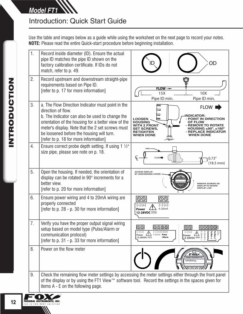
1. Record inside diameter (ID). Ensure the actual pipe ID matches the pipe ID shown on the factory calibration certificate. If IDs do not match, refer to p. 49.
2. Record upstream and downstream straight-pipe requirements based on Pipe ID.[refer to p. 17 for more information]
3. a. The Flow Direction Indicator must point in the direction of flow.b. The Indicator can also be used to change the orientation of the housing for a better view of the meter's display. Note that the 2 set screws must be loosened before the housing will turn.[refer to p. 18 for more information]
4. Ensure correct probe depth setting. If using 1 ½" size pipe, please see note on p. 18.
5. Open the housing. If needed, the orientation of display can be rotated in 90° increments for a better view. [refer to p. 20 for more information]
6. Ensure power wiring and 4 to 20mA wiring are properly connected[refer to p. 28 - p. 30 for more information]
7. Verify you have the proper output signal wiring setup based on model type (Pulse/Alarm or communication protocol)[refer to p. 31 - p. 33 for more information]
8. Power on the flow meter
9. Check the remaining flow meter settings by accessing the meter settings either through the front panel of the display or by using the FT1 View™ software tool. Record the settings in the spaces given for items A - E on the following page.
Use the table and images below as a guide while using the worksheet on the next page to record your notes.NOTE: Please read the entire Quick-start procedure before beginning installation.
ID OD
FLOW10X
Pipe ID min.15X
Pipe ID min.
INDICATOR: - POINT IN DIRECTION OF FLOW - REMOVE TO ROTATE HOUSING ±90º, ±180º - REPLACE INDICATOR WHEN DONE
LOOSEN HOUSINGWITH 2 FRONT SET SCREWS, RETIGHTEN WHEN DONE
FLOW
FLOW
PIPE
0.73" (18.5 mm)
LC
F1 F2 F3 F4
ACCESS DISPLAYBY UNSCREWING COVER
REMOVE SCREWS ON DISPLAY TO ROTATE DISPLAY ±180°
(-) (+) (-) (+) (-) (+)Power12-28VDC
4-20mA Pulse/Alarm
!
(-) (+) (-) (+) (-) (+)Power12-28VDC
4-20mA Pulse/Alarm
! (-) (+)Power12-28VDC
4-20mA
(-)
!
4-20mA
(+)
Common
Tx/Rx(-)
Tx/Rx(+)
F1 F2 F3 F4
Initializing...
12
Model FT1D
ISC
LAIM
ER
12
INTR
OD
UC
TIO
N
Introduction: Quick Start Guide

Item to verifySerial Number: Serial Number: Serial Number: Serial Number:
1. What is the Pipe ID? ID = ID = ID = ID =
2. Calculate the Upstream/Downstream straight-pipe requirements
UP =DN =
UP =DN =
UP =DN =
UP =DN =
3. a. Is the flow indicator pointed in direction of flow?b. Must the housing be rotated for easy viewing?
Y / N
Y / N
Y / N
Y / N
Y / N
Y / N
Y / N
Y / N
4. Is the probe depth setting correct?
Y / N Y / N Y / N Y / N
5. Have you rotated the display for easier viewing?
Y / N Y / N Y / N Y / N
6. Verify proper power wiring setup
7. Verify proper output wiring setup
After powering on your meter, check items A - E below by accessing the meter settings either through the front panel of the meter's display or by using the FT1 View™ software tool.A. Which flow units have been
set in meter? (SCFM, KG/H, etc..)
B. Correct values for reference temperature and pressure?
Y / N Y / N Y / N Y / N
C. Confirm the pipe ID listed above same as "Pipe_id="
D. Verify the 4mA and 20mA meter settings
4mA =20mA =
4mA =20mA =
4mA =20mA =
4mA =20mA =
E. Confirm the correct gas is selected for your application in the Gas-SelectX® menu
Your Notes:
Before powering on your meter, use this worksheet to record your notes.
If you are experiencing any problems after completing this procedure, please call the Fox Service Department at 831-384-4300 to review this information.
13
Model FT1IN
TR
OD
UC
TIO
N
Introduction: Quick Start Guide

Thank you for purchasing the Model FT1 Thermal Gas Mass Flow Meter from Fox Thermal Instruments. The Model FT1 is one of the most technically advanced flow meters in the world. Extensive engineering effort has been invested to deliver advanced features, accurate measurement performance and outstanding reliability.
This Instruction Manual contains the electrical and mechanical installation instructions as well as details for programming, maintaining and troubleshooting the meter. This manual is divided into the following sections: Introduction, Installation, Wiring, Operation, Maintenance, Troubleshooting, Appendices, Glossary and Index. Theory of OperationThe Model FT1 is an innovative Thermal Mass Gas Flow Meter and Temperature Transmitter. It is microprocessor-based and field programmable. The FT1 thermal sensor operates on the law that gases absorb heat. A heated sensor placed in an air or gas stream transfers heat in proportion to the stream’s mass velocity. There are two sensor elements. One sensor element detects the gas temperature and a second element is maintained at a constant temperature above the gas temperature. The energy transferred from the heated element is proportional to the mass flow velocity. The FT1 flow meter maintains accurate flow measurement over a large temperature and pressure range.
Mass FlowThe Model FT1 measures mass flow; an advantage over other flow meters which measure volumetric flow rate. Volumetric flow is incomplete because temperature and pressure are unknown and must be measured separately. For example, the mass flow of a gas depends on its temperature and pressure. As temperature and pressure changes, the gas volume changes but not its mass. Therefore a device measuring mass flow is independent of temperature and pressure changes. The Model FT1 provides a direct measurement of gas flow in Mass units (kg/hr, lb/hr), standard units (SCFM, SLPM) or normal units (NM3/hr, NLPM) with no additional temperature or pressure measurements required.
Flow CalibrationThe Fox Calibration Lab maintains instrument calibration data on every flow meter. Calibration files include details on process conditions, customer gas, line size and other information. All NIST-traceable equipment utilized for the calibration procedure is identified on the Calibration Certificate, which is sent with every flow meter.
DDC-Sensor™ Technology DescriptionThe 2nd Generation Fox DDC-Sensor™ is a new state of the art sensor technology used in the Fox Model FT1 Thermal Gas Flow Meter. The DDC-Sensor™, a Direct Digitally Controlled sensor, is unlike other thermal flow sensors available on the market. Instead of using traditional analog circuitry, the DDC-Sensor™ is interfaced directly to the FT1 microprocessor for more speed and programmability. The DDC-Sensor™ quickly and accurately responds to changes in process variables by utilizing the microprocessor to determine mass flow rate, totalized flow, and temperature.
14
Model FT1D
ISC
LAIM
ER
14
INTR
OD
UC
TIO
N
Introduction
Product Description
Mass Flow
Welcome
Flow Calibration
DDC-Sensor™ Technology
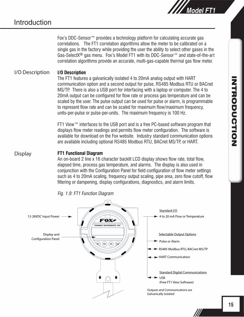
Standard I/O
4 to 20 mA Flow or Temperature
Pulse or Alarm
USB(Free FT1 View Software)
Outputs and Communications are Galvanically Isolated
Selectable Output Options
RS485 Modbus RTU, BACnet MS/TP
HART Communication
Standard Digital Communications
12-28VDC Input Power
Display andCon�guration Panel
F1 F2 F3 F4
Fox’s DDC-Sensor™ provides a technology platform for calculating accurate gas correlations. The FT1 correlation algorithms allow the meter to be calibrated on a single gas in the factory while providing the user the ability to select other gases in the Gas-SelectX® gas menu. Fox’s Model FT1 with its DDC-Sensor™ and state-of-the-art correlation algorithms provide an accurate, multi-gas-capable thermal gas flow meter.
I/O DescriptionThe FT1 features a galvanically isolated 4 to 20mA analog output with HART communication option and a second output for pulse, RS485 Modbus RTU or BACnet MS/TP. There is also a USB port for interfacing with a laptop or computer. The 4 to 20mA output can be configured for flow rate or process gas temperature and can be scaled by the user. The pulse output can be used for pulse or alarm, is programmable to represent flow rate and can be scaled for maximum flow/maximum frequency, units-per-pulse or pulse-per-units. The maximum frequency is 100 Hz.
FT1 View™ interfaces to the USB port and is a free PC-based software program that displays flow meter readings and permits flow meter configuration. The software is available for download on the Fox website. Industry standard communication options are available including optional RS485 Modbus RTU, BACnet MS/TP, or HART.
FT1 Functional DiagramAn on-board 2 line x 16 character backlit LCD display shows flow rate, total flow, elapsed time, process gas temperature, and alarms. The display is also used in conjunction with the Configuration Panel for field configuration of flow meter settings such as 4 to 20mA scaling, frequency output scaling, pipe area, zero flow cutoff, flow filtering or dampening, display configurations, diagnostics, and alarm limits. Fig. 1.9: FT1 Function Diagram
15
Model FT1IN
TR
OD
UC
TIO
N
Introduction
I/O Description
Display
Installation - Model FT1 Flow Meter
ScopeThis section describes how to install the Fox Model FT1 Flow Meter and how to get started:
1. Determine lateral position on the pipe 2. Sensor installation depth 3. Sensor orientation in relation to sensor length and direction of flow4. Proper tightening of compression fitting for mounting meter
Installation procedures must be performed using a combination of the end user’s best engineering practices, in compliance with local codes, and manufacturer’s recommendations.
General PrecautionsThe following general precautions should be observed: 1. Exercise care when handling the flow meter to avoid damaging the probe, sensor
or enclosure.2. The enclosure cover must be closed except during installation or configuration.3. Mounting FT1 in direct sunlight can cause the temperature inside the enclosure
to increase beyond design limits, resulting in failure of LCD display and reduced component life. It is recommended that a sunshade be installed to avoid direct sunlight (see maximum enclosure operating temperature specification).
4. Ensure the flow direction indicator/pointer for the meter is in line with the direction of flow in the pipe.
5. Do not install the FT1 enclosure near an igniter, igniter-controller or switching equipment.
6. Do not install an external power supply in a cabinet containing an igniter controller or switching equipment.
7. For accurate flow measurement: review flow meter placement instructions before installation to ensure a proper flow profile in the pipe.
8. For safety reasons, Teflon ferrules are only appropriate for applications with pressures of 60 psig or less. At higher pressures, use of a Teflon ferrule risks unwanted probe movement or ejection of the probe from the pipe. For all applications above 60 psig, the standard stainless steel ferrule is required.
16
Model FT1IN
STALLATIO
N
Installation: General
Insertion Flow Meter Lateral Placement
FLOW
10X Pipe ID min.
ProperFlowPro�le
15X Pipe ID min.
Irregular FlowPro�le
F1 F2 F3 F4
F1 F2 F3 F4
i
i
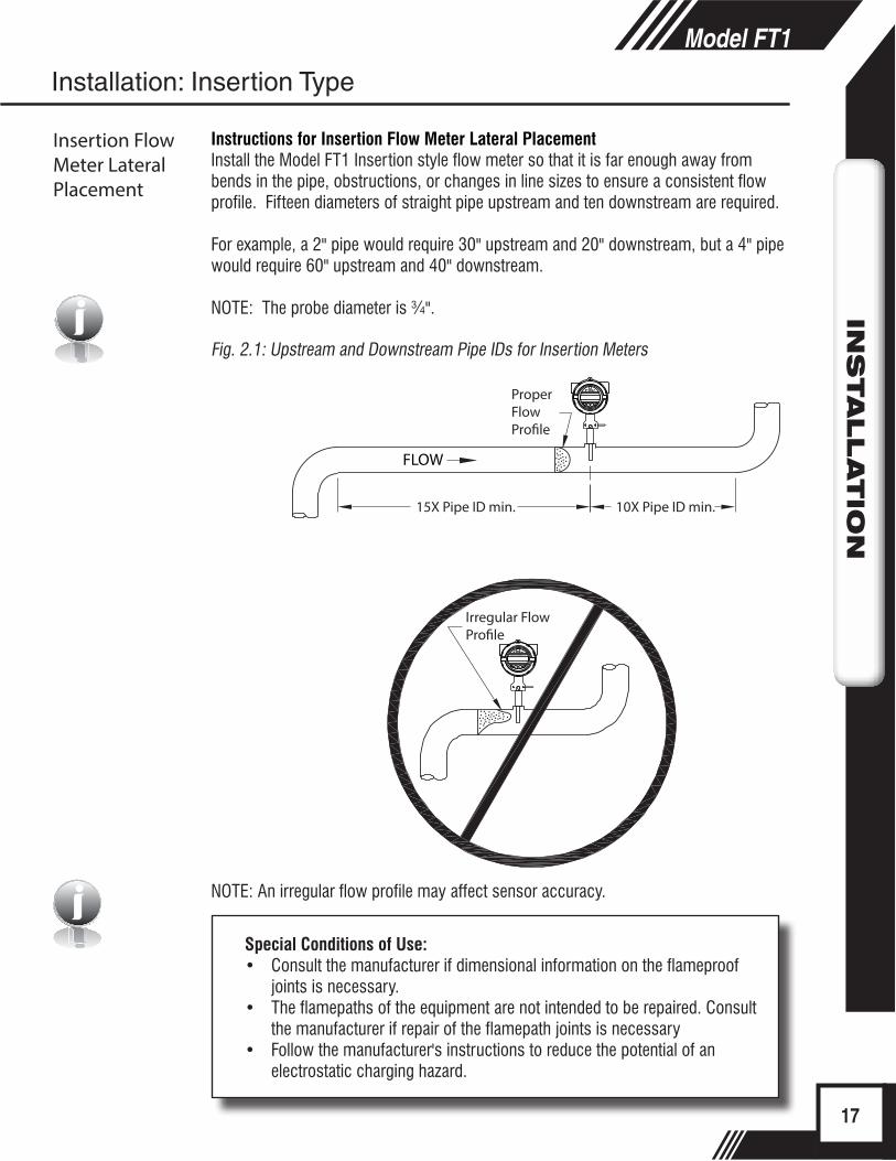
Instructions for Insertion Flow Meter Lateral PlacementInstall the Model FT1 Insertion style flow meter so that it is far enough away from bends in the pipe, obstructions, or changes in line sizes to ensure a consistent flow profile. Fifteen diameters of straight pipe upstream and ten downstream are required.
For example, a 2" pipe would require 30" upstream and 20" downstream, but a 4" pipe would require 60" upstream and 40" downstream.
NOTE: The probe diameter is ¾".
Fig. 2.1: Upstream and Downstream Pipe IDs for Insertion Meters
Special Conditions of Use:• Consult the manufacturer if dimensional information on the flameproof
joints is necessary.• The flamepaths of the equipment are not intended to be repaired. Consult
the manufacturer if repair of the flamepath joints is necessary• Follow the manufacturer's instructions to reduce the potential of an
electrostatic charging hazard.
NOTE: An irregular flow profile may affect sensor accuracy.
17
Model FT1IN
STALLATIO
N
Installation: Insertion Type
Insertion Flow Meter Lateral Placement
"D"
D/2
"L"
MARK ON PROBE
.73[18.5mm]
INSERTION DEPTH:L + D/2 + .73"
CUSTOMER'S PIPEØ.75 PROBE
COMPRESSION FITTING,Ø.75” TUBE, 316 SST,
BY FOX
PROCESS CONNECTION ,1 INCH NPT, FEMALE,
BY CUSTOMER
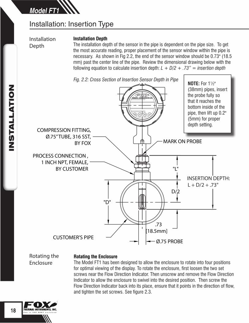
Installation DepthThe installation depth of the sensor in the pipe is dependent on the pipe size. To get the most accurate reading, proper placement of the sensor window within the pipe is necessary. As shown in Fig 2.2, the end of the sensor window should be 0.73" (18.5 mm) past the center line of the pipe. Review the dimensional drawing below with the following equation to calculate insertion depth: L + D/2 + .73” = insertion depth
Fig. 2.2: Cross Section of Insertion Sensor Depth in Pipe
Rotating the EnclosureThe Model FT1 has been designed to allow the enclosure to rotate into four positions for optimal viewing of the display. To rotate the enclosure, first loosen the two set screws near the Flow Direction Indicator. Then unscrew and remove the Flow Direction Indicator to allow the enclosure to swivel into the desired position. Then screw the Flow Direction Indicator back into its place, ensure that it points in the direction of flow, and tighten the set screws. See figure 2.3.
NOTE: For 1½" (38mm) pipes, insert the probe fully so that it reaches the bottom inside of the pipe, then lift up 0.2" (5mm) for proper depth setting.
18
Model FT1IN
STALLATIO
N
Installation: Insertion Type
Installation Depth
Rotating the Enclosure

CUSTOMER
PIPE
Note: Rotational misalignment should not exceed ±5°
TOP VIEW
SIDE VIEW
CUSTOMER
PIPE
+5°
-5°
FLOW
FLOW DIRECTION INDICATOR
SET SCREW
FLOW DIRECTION INDICATOR
FLOW
Direction of Flow and Orientation of the Probe SensorInstall the meter with the flow direction indicator pointing in the direction of flow in the pipe. To rotate the enclosure/probe, unscrew the Flow Direction Indicator and the Set Screws, rotate the housing ±90° or 180°, and return the Flow Direction Indicator and Set Screws in order to secure the new placement.
Fig. 2.3: Orientation of Flow Meter and Rotation of Housing
19
Model FT1IN
STALLATIO
N
Installation: Insertion Type
Sensor Orientation - Direction of Flow
F1 F2 F3 F4
Loosen these two screws to open the display and access
wiring terminals.Loosen these three screws to rotate the display in 90°
increments (±180°).
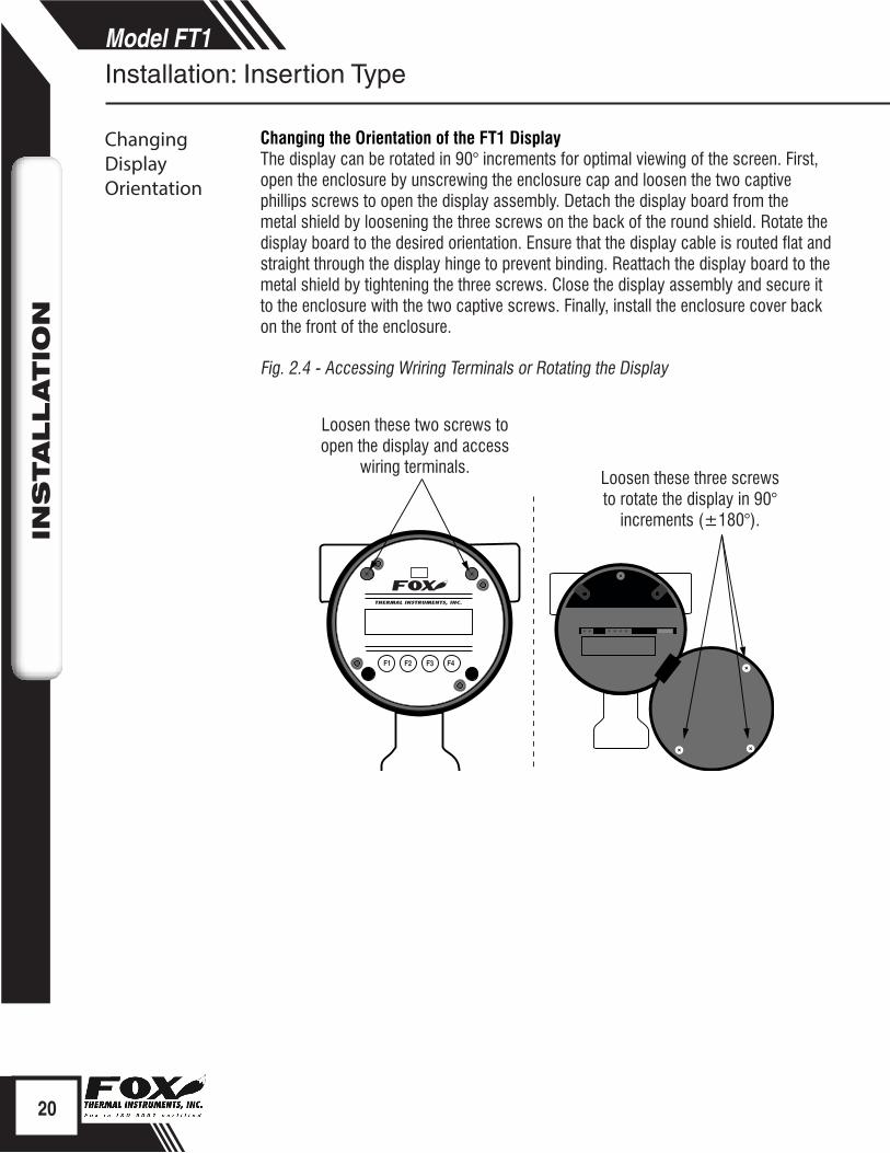
Changing the Orientation of the FT1 DisplayThe display can be rotated in 90° increments for optimal viewing of the screen. First, open the enclosure by unscrewing the enclosure cap and loosen the two captive phillips screws to open the display assembly. Detach the display board from the metal shield by loosening the three screws on the back of the round shield. Rotate the display board to the desired orientation. Ensure that the display cable is routed flat and straight through the display hinge to prevent binding. Reattach the display board to the metal shield by tightening the three screws. Close the display assembly and secure it to the enclosure with the two captive screws. Finally, install the enclosure cover back on the front of the enclosure.
Fig. 2.4 - Accessing Wriring Terminals or Rotating the Display
20
Model FT1IN
STALLATIO
NInstallation: Insertion Type
Changing Display Orientation
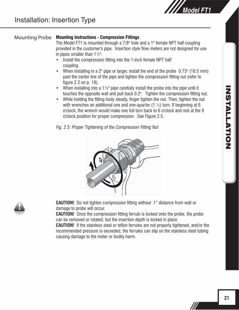
Mounting Instructions - Compression FittingsThe Model FT1 is mounted through a 7/8" hole and a 1" female NPT half coupling provided in the customer's pipe. Insertion style flow meters are not designed for use in pipes smaller than 1½".• Install the compression fitting into the 1-inch female NPT half
coupling.• When installing in a 2" pipe or larger, install the end of the probe 0.73" (18.5 mm)
past the center line of the pipe and tighten the compression fitting nut (refer to figure 2.2 on p. 18).
• When installing into a 1½" pipe carefully install the probe into the pipe until it touches the opposite wall and pull back 0.2". Tighten the compression fitting nut.
• While holding the fitting body steady, finger tighten the nut. Then, tighten the nut with wrenches an additional one and one-quarter (1 ¼) turn. If beginning at 6 o'clock, the wrench would make one full turn back to 6 o'clock and rest at the 9 o'clock position for proper compression. See Figure 2.5.
Fig. 2.5: Proper Tightening of the Compression Fitting Nut
CAUTION! Do not tighten compression fitting without .1” distance from wall or damage to probe will occur.CAUTION! Once the compression fitting ferrule is locked onto the probe, the probe can be removed or rotated, but the insertion depth is locked in place.CAUTION! If the stainless steel or teflon ferrules are not properly tightened, and/or the recommended pressure is exceeded, the ferrules can slip on the stainless steel tubing causing damage to the meter or bodily harm.
21
Model FT1IN
STALLATIO
N
Mounting Probe
Installation: Insertion Type

Collar Clamp
iInstalling a Retractor
Installation of a New Retractor Assembly
NOTE: For instructions on how to properly weld the NPT female fitting onto pipe, please refer to Document #107590.
1. Remove collar clamp from probe using a 3/16" Hex Key.2. Remove meter probe from retractor assembly and leave the ball valve open.3. Install the valve assembly on the pipe, by tightening the Hex Nipple with a 1 3/8"
wrench.
Fig. 2.6: Retractor Assembly With and Without Probe Inserted
22
Model FT1IN
STALLATIO
N
Installation: Retractor Option
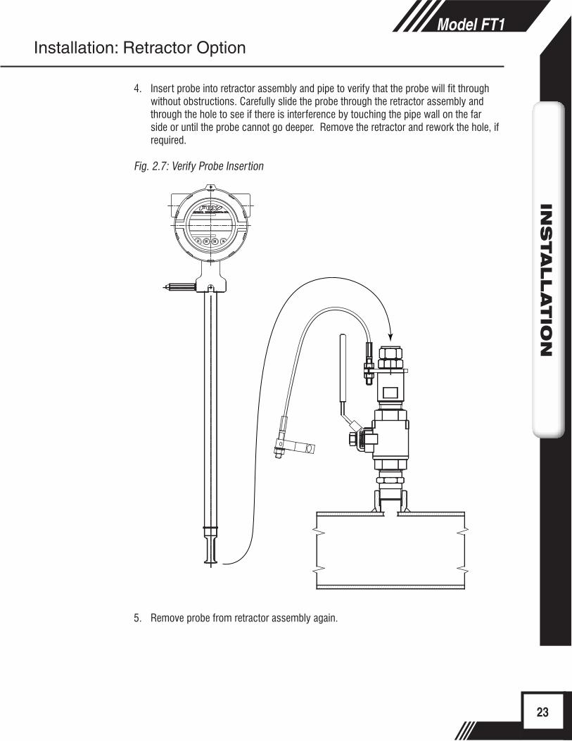
4. Insert probe into retractor assembly and pipe to verify that the probe will fit through without obstructions. Carefully slide the probe through the retractor assembly and through the hole to see if there is interference by touching the pipe wall on the far side or until the probe cannot go deeper. Remove the retractor and rework the hole, if required.
Fig. 2.7: Verify Probe Insertion
5. Remove probe from retractor assembly again.
23
Model FT1IN
STALLATIO
NInstallation: Retractor Option
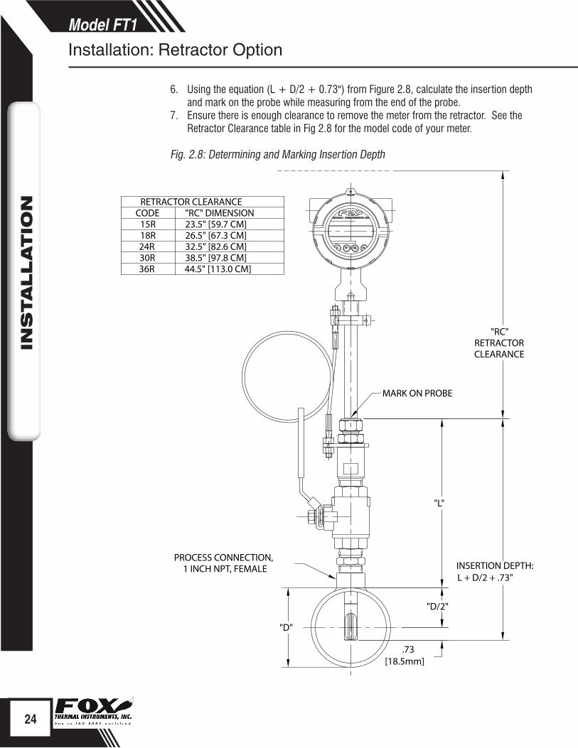
"D"
.73[18.5mm]
"D/2"
"L"
PROCESS CONNECTION,1 INCH NPT, FEMALE
"RC"RETRACTORCLEARANCE
MARK ON PROBE
INSERTION DEPTH:L + D/2 + .73"
RETRACTOR CLEARANCECODE
23.5" [59.7 CM]15R26.5" [67.3 CM]18R32.5" [82.6 CM]24R38.5" [97.8 CM]30R44.5" [113.0 CM]36R
"RC" DIMENSION
6. Using the equation (L + D/2 + 0.73") from Figure 2.8, calculate the insertion depth and mark on the probe while measuring from the end of the probe.
7. Ensure there is enough clearance to remove the meter from the retractor. See the Retractor Clearance table in Fig 2.8 for the model code of your meter.
Fig. 2.8: Determining and Marking Insertion Depth
24
Model FT1IN
STALLATIO
N
Installation: Retractor Option
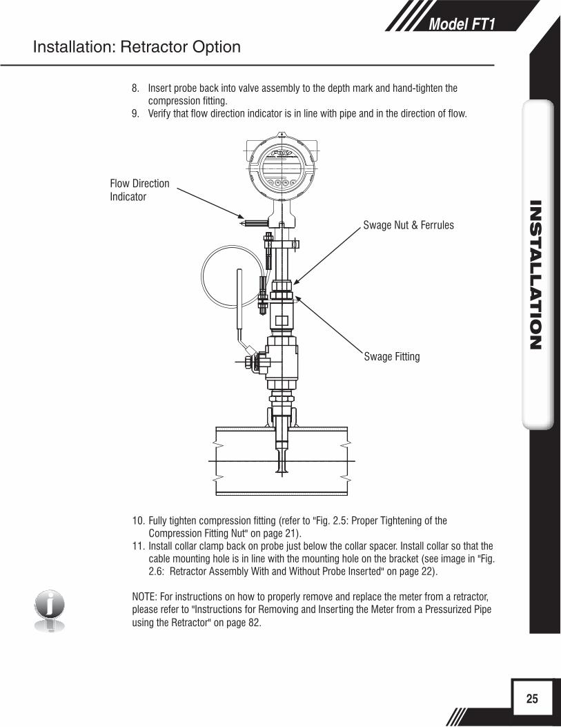
Swage Nut & Ferrules
Flow Direction Indicator
Swage Fitting
i
8. Insert probe back into valve assembly to the depth mark and hand-tighten the compression fitting.
9. Verify that flow direction indicator is in line with pipe and in the direction of flow.
10. Fully tighten compression fitting (refer to "Fig. 2.5: Proper Tightening of the Compression Fitting Nut" on page 21).
11. Install collar clamp back on probe just below the collar spacer. Install collar so that the cable mounting hole is in line with the mounting hole on the bracket (see image in "Fig. 2.6: Retractor Assembly With and Without Probe Inserted" on page 22).
NOTE: For instructions on how to properly remove and replace the meter from a retractor, please refer to "Instructions for Removing and Inserting the Meter from a Pressurized Pipe using the Retractor" on page 82.
25
Model FT1IN
STALLATIO
NInstallation: Retractor Option
Wiring InstructionsTo wire the FT1, unscrew and remove the enclosure cap. If the meter has the display option, loosen the two captive screws on the display assembly and rotate it open to access the wiring terminals. Connect the power and signal wires to the terminal blocks according to the label and instructions on the following pages.
Cut all wires as short as allowable for a minimum service loop. Obtain the correct length for the FT1 wires using one of these methods:
• Trim the wires to extend 2 inches out of the enclosure after the conduit and wires are routed to the FT1.
• Trim the wires to extend 5 inches from the end of the conduit before attaching them to the FT1.
Wiring Precautions - WARNING!
• Do not open the enclosure when energized or an explosive atmosphere is present.
• Connect earth ground to a chassis ground screw on the inside or outside of FT1 enclosure to reduce the potential of an electrostatic charging hazard.
• All plumbing and electrical installations of flow meters must be in compliance with local codes, the end user’s best engineering practices, and manufacturer’s recommendations.
• Do not install the FT1 enclosure near an igniter, igniter-controller or switching equipment to eliminate the possibility of noise interference.
• Do not install an external power supply in a cabinet containing an igniter controller or switching equipment.
• This flow meter contains components that can be damaged by static electricity. You must discharge yourself by touching a grounded steel pipe or other grounded metal prior to working inside this flow meter.
• Close any unused conduit entries using suitably certified plugs
26
Model FT1W
IRIN
G
Scope
Precautions
Power Wiring
Signal Wiring
Wiring: General Wiring: General
Power Wiring For wiring the 12 to 28VDC power, use stranded copper wire, no larger than 16-gauge. Twisted pair shielded cable is recommended. Supply connection wiring must be rated for at least 90°C.
GroundingThe enclosure must be properly grounded with a quality earth ground. 16 gauge, stranded wire is recommended.
Signal WiringFor signal and serial communication wiring, the recommended wire gauge is 18 to 22 AWG. Always use twisted pair shielded cable.
27
Model FT1W
IRIN
G
Power Wiring
Grounding
Signal Wiring
Wiring: General

(-) (+) (-) (+) (-) (+)Power12-28VDC
4-20mA Pulse/Alarm
!
Earth Ground
+12 to 28VDC 12 to 28VDC Return
CAUTION!• Supply connection wiring must be rated for at least 90°C.
Power Input Requirements: 12 to 28VDC SupplyExternal DC power supply must provide 12 to 28VDC (10 to 30VDC full input power range) at 6 Watts minimum.
(With 12VDC power, the FT1 can use up to 500mA. With 24VDC power, the FT1 can use up to 250mA.)
A 20 Watt or greater power supply is recommended to ensure it can provide enough current under all temperature, ventilation and power on conditions.
The enclosure must be properly grounded with a quality earth ground. Sixteen (16) gauge, stranded wire, is recommended for power and earth ground.
Fig. 3.1: Connections for 12 to 28VDC Supply
28
Model FT1W
IRIN
G
Wiring: Input Power
Power Input Wiring
(-) (+) (-) (+) (-) (+)Power12-28VDC
4-20mA Pulse/Alarm
!
+12 to 28VDC
12 to 28VDC Return
+
-
FT1Customer PLC or DCS
4 to 20mA Flow Rate or Temperature250 ohms typical with 24VDC Power125 ohms or less for 12VDC Power*(see note below)
i
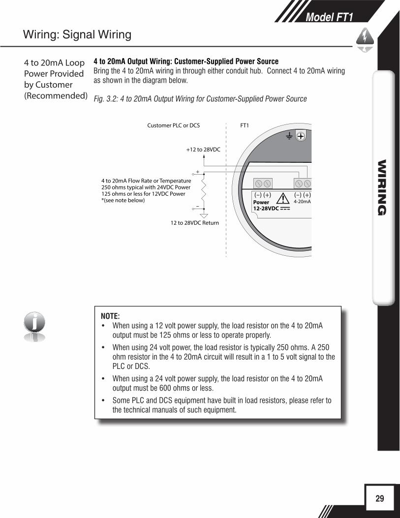
4 to 20mA Output Wiring: Customer-Supplied Power SourceBring the 4 to 20mA wiring in through either conduit hub. Connect 4 to 20mA wiring as shown in the diagram below.
Fig. 3.2: 4 to 20mA Output Wiring for Customer-Supplied Power Source
NOTE: • When using a 12 volt power supply, the load resistor on the 4 to 20mA
output must be 125 ohms or less to operate properly.
• When using 24 volt power, the load resistor is typically 250 ohms. A 250 ohm resistor in the 4 to 20mA circuit will result in a 1 to 5 volt signal to the PLC or DCS.
• When using a 24 volt power supply, the load resistor on the 4 to 20mA output must be 600 ohms or less.
• Some PLC and DCS equipment have built in load resistors, please refer to the technical manuals of such equipment.
29
Model FT1W
IRIN
G
Wiring: Signal Wiring
4 to 20mA Loop Power Provided by Customer(Recommended)

(-) (+) (-) (+) (-) (+)Power12-28VDC
4-20mA Pulse/Alarm
!
4 to 20mA Flow Rate or Temperature250 ohms typical with 24VDC Power125 ohms or less for 12VDC Power*(see note below)
+
-
FT1Customer PLC or DCS
+12 to 28VDC 12 to 28VDC Return
i
4 to 20mA Output Wiring: Loop Power Provided by FT1Bring the 4 to 20mA wiring in through either conduit hub. Connect the 4 to 20mA as shown in the diagram below.
Fig. 3.3: 4 to 20mA Output Wiring for Loop Power Provided by FT1
NOTE: • When using a 12 volt power supply, the load resistor on the 4 to 20mA
output must be 125 ohms or less to operate properly.
• When using 24 volt power, the load resistor is typically 250 ohms. A 250 ohm resistor in the 4 to 20mA circuit will result in a 1 to 5 volt signal to the PLC or DCS.
• When using a 24 volt power supply, the load resistor on the 4 to 20mA output must be 600 ohms or less.
• Some PLC and DCS equipment have built in load resistors, please refer to the technical manuals of such equipment.
30
Model FT1W
IRIN
G
Wiring: Signal Wiring
4 to 20mA Loop Power Provided by FT1
(-) (+) (-) (+) (-) (+)Power12-28VDC
4-20mA Pulse/Alarm
!
+12 to 28VDC
Pulse or Alarm Output
12 to 28VDC Return
+-
FT1Customer PLC or DCS
2.4K Ohm typical with 24VDC Power1.2K Ohm typical with 12VDC Power
i
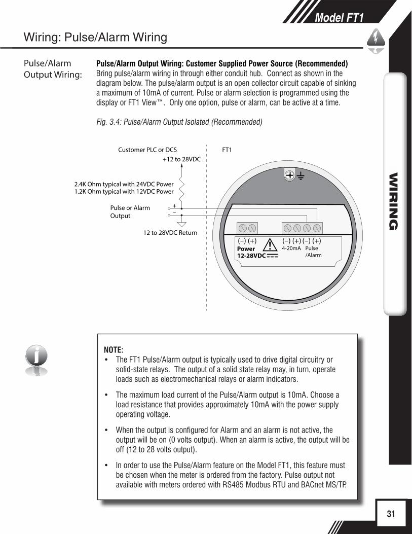
Pulse/Alarm Output Wiring: Customer Supplied Power Source (Recommended)Bring pulse/alarm wiring in through either conduit hub. Connect as shown in the diagram below. The pulse/alarm output is an open collector circuit capable of sinking a maximum of 10mA of current. Pulse or alarm selection is programmed using the display or FT1 View™. Only one option, pulse or alarm, can be active at a time.
Fig. 3.4: Pulse/Alarm Output Isolated (Recommended)
NOTE: • The FT1 Pulse/Alarm output is typically used to drive digital circuitry or
solid-state relays. The output of a solid state relay may, in turn, operate loads such as electromechanical relays or alarm indicators.
• The maximum load current of the Pulse/Alarm output is 10mA. Choose a load resistance that provides approximately 10mA with the power supply operating voltage.
• When the output is configured for Alarm and an alarm is not active, the output will be on (0 volts output). When an alarm is active, the output will be off (12 to 28 volts output).
• In order to use the Pulse/Alarm feature on the Model FT1, this feature must be chosen when the meter is ordered from the factory. Pulse output not available with meters ordered with RS485 Modbus RTU and BACnet MS/TP.
31
Model FT1W
IRIN
GModel FT1
WIR
ING
Wiring: Pulse/Alarm Wiring
Pulse/Alarm Output Wiring:
(-) (+) (-) (+) (-) (+)Power12-28VDC
4-20mA Pulse/Alarm
!
Pulse or Alarm Output
+-
FT1Customer PLC or DCS
+12 to 28VDC 12 to 28VDC Return
2.4K Ohm typical with 24VDC Power1.2K Ohm typical with 12VDC Power
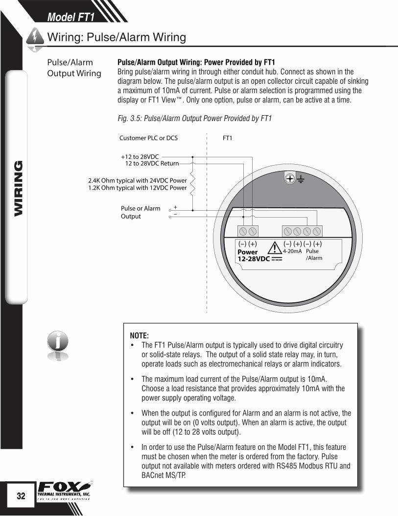
i NOTE: • The FT1 Pulse/Alarm output is typically used to drive digital circuitry
or solid-state relays. The output of a solid state relay may, in turn, operate loads such as electromechanical relays or alarm indicators.
• The maximum load current of the Pulse/Alarm output is 10mA. Choose a load resistance that provides approximately 10mA with the power supply operating voltage.
• When the output is configured for Alarm and an alarm is not active, the output will be on (0 volts output). When an alarm is active, the output will be off (12 to 28 volts output).
• In order to use the Pulse/Alarm feature on the Model FT1, this feature must be chosen when the meter is ordered from the factory. Pulse output not available with meters ordered with RS485 Modbus RTU and BACnet MS/TP.
Pulse/Alarm Output Wiring: Power Provided by FT1Bring pulse/alarm wiring in through either conduit hub. Connect as shown in the diagram below. The pulse/alarm output is an open collector circuit capable of sinking a maximum of 10mA of current. Pulse or alarm selection is programmed using the display or FT1 View™. Only one option, pulse or alarm, can be active at a time.
Fig. 3.5: Pulse/Alarm Output Power Provided by FT1
32
Model FT1W
IRIN
G
32
Model FT1W
IRIN
G
Wiring: Pulse/Alarm Wiring
Pulse/Alarm Output Wiring
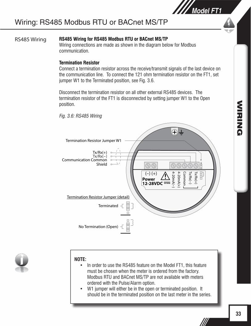
i NOTE:• In order to use the RS485 feature on the Model FT1, this feature
must be chosen when the meter is ordered from the factory. Modbus RTU and BACnet MS/TP are not available with meters ordered with the Pulse/Alarm option.
• W1 jumper will either be in the open or terminated position. It should be in the terminated position on the last meter in the series.
33
Model FT1W
IRIN
G
(-) (+)Power12-28VDC
4-20mA
(-)
!
4-20mA
(+)
Comm
on
Tx/Rx(-)
Tx/Rx(+)
Tx/Rx(+)
Termination Resistor Jumper W1
Tx/Rx(-)Communication Common
Termination Resistor Jumper (detail)
Terminated
No Termination (Open)
Shield
RS485 Wiring for RS485 Modbus RTU or BACnet MS/TPWiring connections are made as shown in the diagram below for Modbus communication.
Termination ResistorConnect a termination resistor across the receive/transmit signals of the last device on the communication line. To connect the 121 ohm termination resistor on the FT1, set jumper W1 to the Terminated position, see Fig. 3.6.
Disconnect the termination resistor on all other external RS485 devices. The termination resistor of the FT1 is disconnected by setting jumper W1 to the Open position.
Fig. 3.6: RS485 Wiring
Wiring: RS485 Modbus RTU or BACnet MS/TP
RS485 Wiring
i
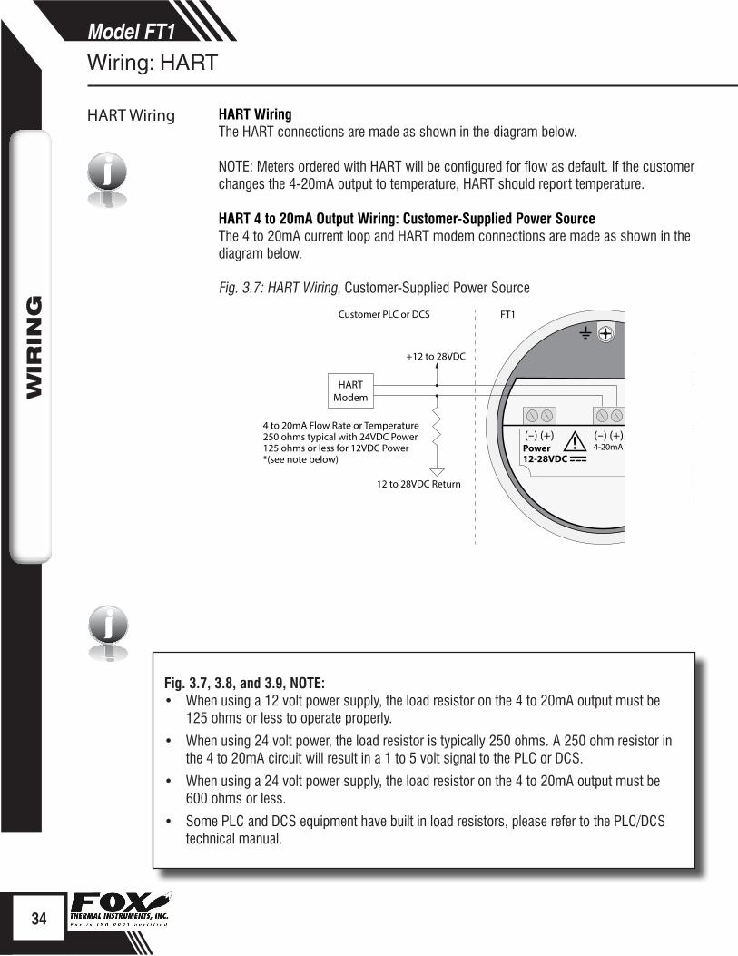
Fig. 3.7, 3.8, and 3.9, NOTE: • When using a 12 volt power supply, the load resistor on the 4 to 20mA output must be
125 ohms or less to operate properly.
• When using 24 volt power, the load resistor is typically 250 ohms. A 250 ohm resistor in the 4 to 20mA circuit will result in a 1 to 5 volt signal to the PLC or DCS.
• When using a 24 volt power supply, the load resistor on the 4 to 20mA output must be 600 ohms or less.
• Some PLC and DCS equipment have built in load resistors, please refer to the PLC/DCS technical manual.
34
Model FT1W
IRIN
GWiring: HART
HART Wiring
i
(-) (+) (-) (+) (-) (+)Power12-28VDC
4-20mA Pulse/Alarm
!
+12 to 28VDC
12 to 28VDC Return
FT1Customer PLC or DCS
HARTModem
4 to 20mA Flow Rate or Temperature250 ohms typical with 24VDC Power125 ohms or less for 12VDC Power*(see note below)
HART WiringThe HART connections are made as shown in the diagram below.
NOTE: Meters ordered with HART will be configured for flow as default. If the customer changes the 4-20mA output to temperature, HART should report temperature.
HART 4 to 20mA Output Wiring: Customer-Supplied Power SourceThe 4 to 20mA current loop and HART modem connections are made as shown in the diagram below.
Fig. 3.7: HART Wiring, Customer-Supplied Power Source

35
Model FT1W
IRIN
G
Wiring: HART
HART 4 to 20mA Wiring
(-) (+) (-) (+)TP12(+)TP13(-)
(-) (+)Power12-28VDC
4-20mA Pulse/Alarm
+12 to 28VDC
12 to 28VDC Return
FT1Customer PLC or DCS
HARTHandheld
Communicator
4 to 20mA Flow Rate or Temperature250 ohms typical with 24VDC Power125 ohms or less for 12VDC Power*(see note on previous page)
HART 4 to 20mA Output Wiring: Handheld CommunicatorThe 4 to 20mA current loop connections are made as shown in the diagram below.
A hand-held HART communicator can be connected to test points TP12 (+) and TP13 (-) with clip leads or to the 4 to 20mA terminal block.
Fig. 3.8: HART 4 to 20mA Output Wiring, Handheld Communicator
(-) (+) (-) (+) (-) (+)Power12-28VDC
4-20mA Pulse/Alarm
!
FT1Customer PLC or DCS
+12 to 28VDC 12 to 28VDC Return
HARTModem
4 to 20mA Flow Rate or Temperature250 ohms typical with 24VDC Power125 ohms or less for 12VDC Power*(see note on previous page)
HART 4 to 20mA Output Wiring: Loop Power Provided by FT1The 4 to 20mA current loop and HART modem connections are made as shown in the diagram below.
Fig. 3.9: HART 4 to 20mA Output Wiring, Loop Power Provided by FT1

i
Start Up SequenceThe program automatically enters the Run/Measure mode after power up. The screen will show the software version of the FT1 during power up.
USB InterfaceThe USB interface is a standard feature which allows communication with a PC to monitor readings and configure settings. FT1 View™, is a free application program from Fox that connects to the USB interface and allows data monitoring, configuration setting, data logging to Excel, and an option to save and recall FT1 configuration data.
FT1 Display and Configuration PanelThe FT1 has a 2 line x 16 character display with 4 mechanical buttons. The meter can be programmed by using the display and configuration panel. The configuration panel can be accessed by removing the FT1 cap. Be sure to replace the cap after you are done configuring the FT1.
Fig. 4.1: FT1 Display and Configuration Panel
Display Screen
Mechanical (Push) Buttons F2 F3
36
Model FT1O
PER
ATIO
NModel FT1
OPER
ATIO
N
Operation: Start Up
Start UpSequence
FT1 Display
USB Interface
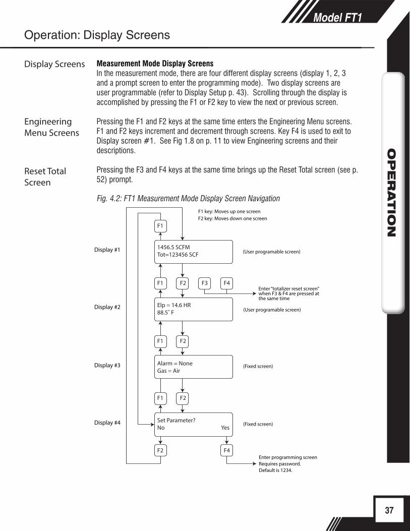
Measurement Mode Display ScreensIn the measurement mode, there are four different display screens (display 1, 2, 3 and a prompt screen to enter the programming mode). Two display screens are user programmable (refer to Display Setup p. 43). Scrolling through the display is accomplished by pressing the F1 or F2 key to view the next or previous screen.
Pressing the F1 and F2 keys at the same time enters the Engineering Menu screens. F1 and F2 keys increment and decrement through screens. Key F4 is used to exit to Display screen #1. See Fig 1.8 on p. 11 to view Engineering screens and their descriptions.
Pressing the F3 and F4 keys at the same time brings up the Reset Total screen (see p. 52) prompt.
Fig. 4.2: FT1 Measurement Mode Display Screen Navigation
37
Model FT1O
PER
ATIO
NModel FT1
OPER
ATIO
N
Display Screens
F1 key: Moves up one screenF2 key: Moves down one screen
(User programable screen)
(User programable screen)
Enter “totalizer reset screen” when F3 & F4 are pressed at the same time
(Fixed screen)
Enter programming screenRequires password.Default is 1234.
Display #1
Display #2
Display #3
Display #4 (Fixed screen)
F1
F1
F1
F1 F2
F2 F4
F2
F2 F3 F4
1456.5 SCFMTot=123456 SCF
Elp = 14.6 HR88.5˚ F
Alarm = NoneGas = Air
Set Parameter?No Yes
Operation: Display Screens
Engineering Menu Screens
Reset Total Screen

Data Entry using the Display and Configuration PanelThere are 2 basic types of menu entries: one for changing value or string and one for selecting from a selection list.
To Change a Value or String :
F1 F2 F3 F4
Press CHG (F1) key to change the value, OK (F4) to accept the value.
F1 F2 F3 F4
Press the UP (F1) or DN (F2) key to select a new digit or character, the cursor points to the selected digit. Press NXT (F3) to select the next digit and OK (F4) to accept the entry.
To Select from a List:
F1 F2 F3 F4
Press NXT (F1) key repeatedly until the correct selection is made and OK (F4) key to accept the entry.
Entering the Programming ModeTo enter the programming mode and access the Main Menu, press the F1 or F2 key in the normal running mode until the following screen is shown:
F1 F2 F3 F4
Press YES (F4) and the following screen will prompt user to enter password:
F1 F2 F3 F4
38
Model FT1O
PER
ATIO
N
Operation: Programming
Programming by Display
Value or String
Selecting from a List
Enter Programming Mode
VALUE = 0.91234UP DN NXT OK
FLO UNT = SCFMNXT OK
SET PARAMETERS ?No Yes
VALUE = 0.91234CHG OK
PASWD:_UP DN NXT OK
Programming by Display
Enter the correct password, then follow the instructions for changing a value as specified on page p. 38. The default Level 1 password is “1234”.
If the wrong password is entered, the message “Wrong Password” will display and then return to the programming entry screen. Main MenuIf the password is accepted, the Main Menu screen will be shown:
F1 F2 F3 F4
This is the Main Menu screen for the programming mode.
Press EXIT (F4) repeatedly until “Normal Mode” is seen briefly to exit the programming mode.
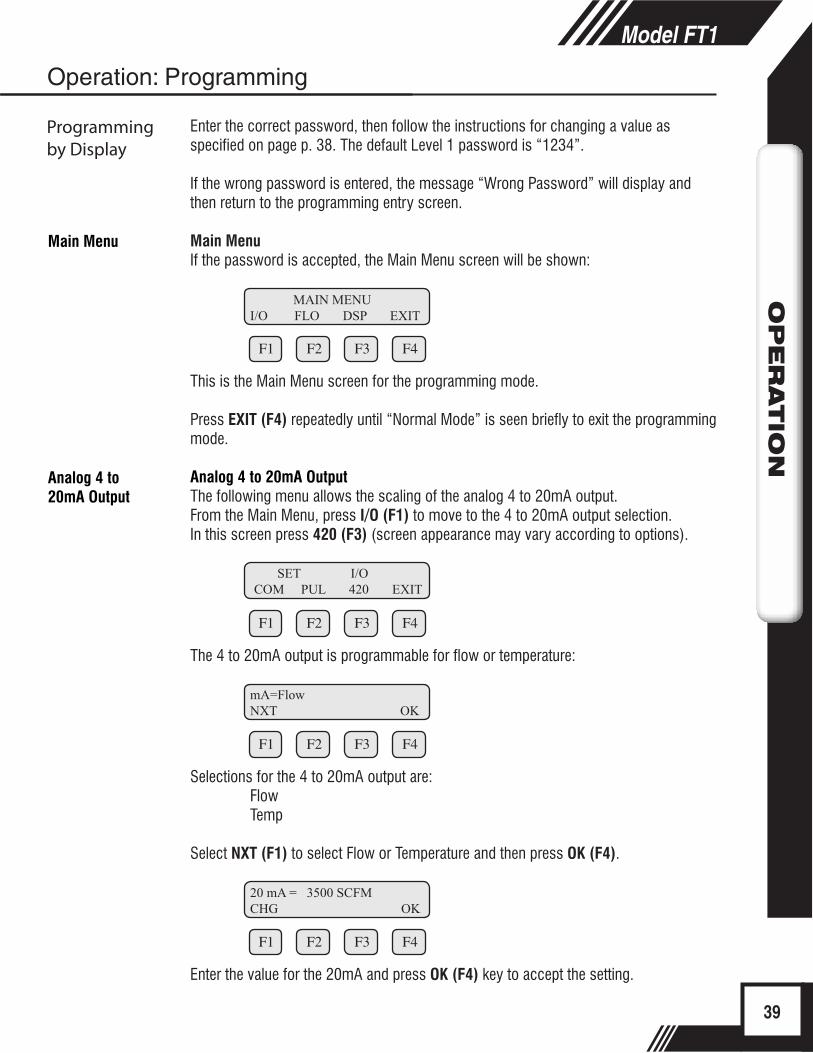
Analog 4 to 20mA OutputThe following menu allows the scaling of the analog 4 to 20mA output.From the Main Menu, press I/O (F1) to move to the 4 to 20mA output selection.In this screen press 420 (F3) (screen appearance may vary according to options).
F1 F2 F3 F4
The 4 to 20mA output is programmable for flow or temperature:
F1 F2 F3 F4
Selections for the 4 to 20mA output are:FlowTemp
Select NXT (F1) to select Flow or Temperature and then press OK (F4).
F1 F2 F3 F4
Enter the value for the 20mA and press OK (F4) key to accept the setting.
39
Model FT1O
PER
ATIO
N
Operation: Programming
Programming by Display
Analog 4 to 20mA Output
Main Menu
MAIN MENUI/O FLO DSP EXIT
mA=FlowNXT OK
20 mA = 3500 SCFMCHG OK
SET I/O COM PUL 420 EXIT

i
i
Then the following screen will display:
F1 F2 F3 F4
Enter the value for the 4mA and press OK (F4).
NOTE: 4mA is normally set to 0.
F1 F2 F3 F4
This menu allows the user to select an alarm fault level on the 4 to 20mA output. The alarm is activated when a serious issue is detected preventing the calculation of the correct flow rate. The 3.6mA and 21mA alarm outputs are related to the NAMUR alarm feature.
The options are:mA Fault=3.6 mA (Force the 4 to 20mA signal to 3.6mA on alarm)mA Fault=21 mA (Force the 4 to 20mA signal to 21mA on alarm)mA Fault=Not use (4 to 20mA signal alarm fault not used)
From any screen, press (F4) repeatedly until “Normal Mode” is seen briefly to exit the programming mode.
NOTE: When the flow rate exceeds the programmed value for the 20mA set point, the analog output will stay at 20mA and an alarm code will be generated.
Pulse/alarm OutputIf the Pulse/alarm feature was purchased as the second output for the Model FT1, it can be accessed from the main menu, press I/O (F1) (screen appearance may vary).
F1 F2 F3 F4
Press PUL (F2) to select the pulse output. The following screen will show:
F1 F2 F3 F4
Press NEXT (F1) to cycle through output options until you have the selection for "OUT=Pulse" and press OK (F4).
40
Model FT1O
PER
ATIO
N
Operation: Programming
Programming by Display
4 mA = 0 SCFMCHG OK
mA Fault = Not useNXT OK
Pulse/alarm Output
SET I/OCOM PUL 420 EXIT
OUT = PulseNXT OK

i
The pulse output can be configured in one of three ways: 1. Specifying how many pulses per unit, P/U (i.e., 10 pulses per SCF)2. Specifying how many flow units total per pulse, U/P (i.e., 0.1 SCF per pulse) 3. Specifying a maximum frequency to a defined maximum value of flow rate
All of these approaches are equivalent.
F1 F2 F3 F4
Use P/U (F1) to enter pulse per unit, U/P (F2) for unit per pulse or FEQ (F3) to enter the flow and maximum frequency to scale the pulse/alarm output.
NOTE: When data is entered with any of the three described methods, the other values will be re-calculated according to the settings.
Entering data in Pulse per Unit:From the Pulse/alarm Output Menu above, press P/U (F1) and the following screen will show:
F1 F2 F3 F4
Press CHG (F1) to change the setting and then OK (F4) to accept entry.
The value entered is in pulse per selected flow unit total (i.e., 2 pulses per SCF).
Entering data in Unit per Pulse:From the Pulse/alarm Output Menu above, press U/P (F2) and the following screen will show:
F1 F2 F3 F4
Press CHG (F1) to change the setting and then OK (F4) to accept entry.The value entered is in unit per pulse (i.e. 0.5 flow unit total per pulse)
Entering data with flow and maximum frequency:From the Pulse/alarm Output Menu above, press FEQ (F3) and the following screen will show:
41
Model FT1O
PER
ATIO
N
Operation: Programming
Programming by Display
Pulse per Unit
PULSE OUTPUT P/U U/P FEQ EXIT
PLS/UNT = 2CHG OK
Unit per Pulse
Max Flow and Frequency
UNT/PLS = 0.5CHG OK
i
F1 F2 F3 F4
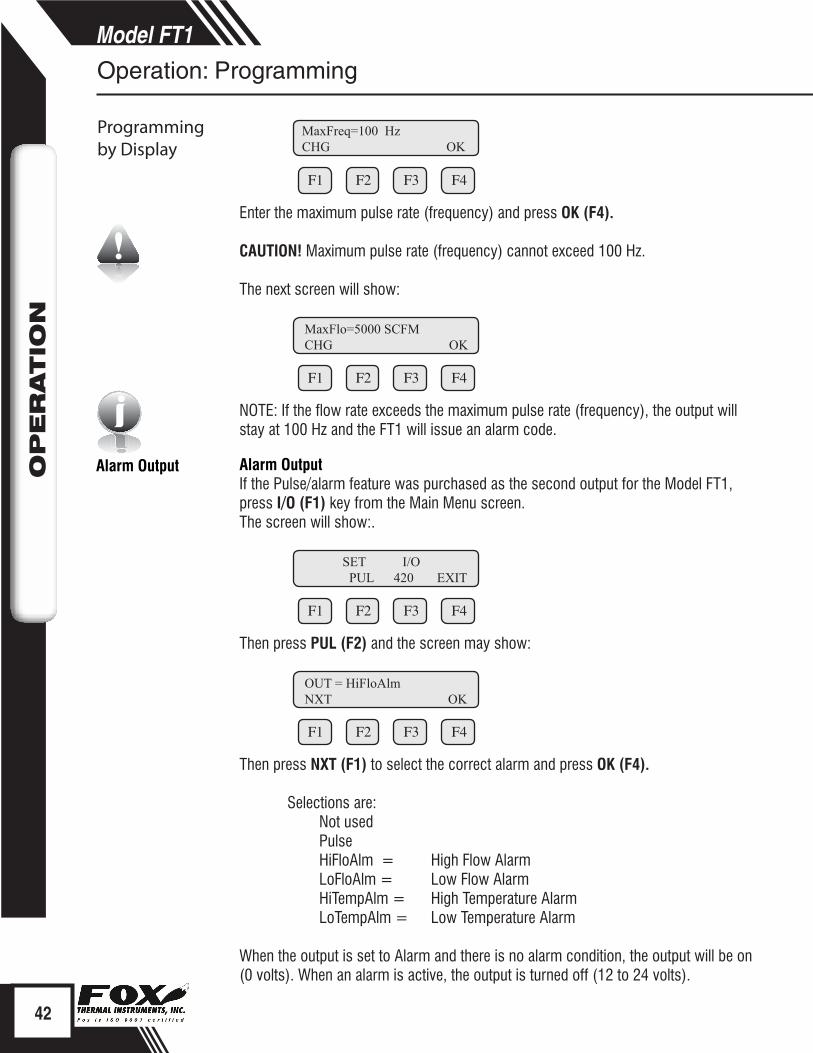
Enter the maximum pulse rate (frequency) and press OK (F4).
CAUTION! Maximum pulse rate (frequency) cannot exceed 100 Hz.
The next screen will show:
F1 F2 F3 F4
NOTE: If the flow rate exceeds the maximum pulse rate (frequency), the output will stay at 100 Hz and the FT1 will issue an alarm code.
Alarm OutputIf the Pulse/alarm feature was purchased as the second output for the Model FT1, press I/O (F1) key from the Main Menu screen. The screen will show:.
F1 F2 F3 F4
Then press PUL (F2) and the screen may show:
F1 F2 F3 F4
Then press NXT (F1) to select the correct alarm and press OK (F4).
Selections are:Not usedPulseHiFloAlm = High Flow AlarmLoFloAlm = Low Flow AlarmHiTempAlm = High Temperature AlarmLoTempAlm = Low Temperature Alarm
When the output is set to Alarm and there is no alarm condition, the output will be on (0 volts). When an alarm is active, the output is turned off (12 to 24 volts).
42
Model FT1O
PER
ATIO
N
Operation: Programming
Programming by Display
MaxFreq=100 HzCHG OK
MaxFlo=5000 SCFMCHG OK
SET I/O PUL 420 EXIT
Alarm Output
OUT = HiFloAlmNXT OK
i
iDisplay Setup
Serial Communication
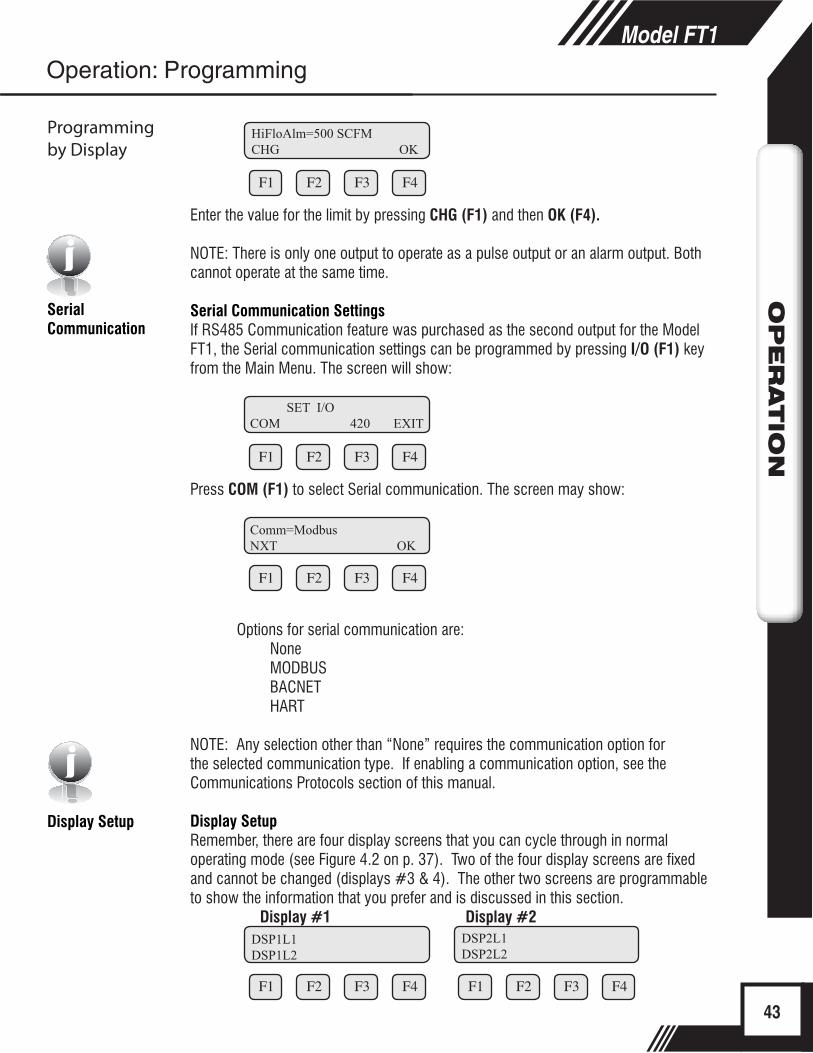
F1 F2 F3 F4
Enter the value for the limit by pressing CHG (F1) and then OK (F4).
NOTE: There is only one output to operate as a pulse output or an alarm output. Both cannot operate at the same time.
Serial Communication SettingsIf RS485 Communication feature was purchased as the second output for the Model FT1, the Serial communication settings can be programmed by pressing I/O (F1) key from the Main Menu. The screen will show:
F1 F2 F3 F4
Press COM (F1) to select Serial communication. The screen may show:
F1 F2 F3 F4
Options for serial communication are:NoneMODBUSBACNETHART
NOTE: Any selection other than “None” requires the communication option for the selected communication type. If enabling a communication option, see the Communications Protocols section of this manual.
Display SetupRemember, there are four display screens that you can cycle through in normal operating mode (see Figure 4.2 on p. 37). Two of the four display screens are fixed and cannot be changed (displays #3 & 4). The other two screens are programmable to show the information that you prefer and is discussed in this section.
Display #1 Display #2
F1 F2 F3 F4
F1 F2 F3 F4
43
Model FT1O
PER
ATIO
N
Programming by Display
Operation: Programming
HiFloAlm=500 SCFMCHG OK
SET I/OCOM 420 EXIT
Comm=ModbusNXT OK
DSP1L1DSP1L2
DSP2L1DSP2L2

Programming Display Screens #1 & 2
Selections are:DSP1L1 Display 1, Line 1DSP1L2 Display 1, Line 2DSP2L1 Display 2, Line 1DSP2L2 Display 2, Line 2
To Program Display Screens #1 & 2:From the Main Menu press DSP (F3) to select the display menu:
F1 F2 F3 F4
Press DSP (F1) key. The display will show:
F1 F2 F3 F4
These are the selections for the display #1 line #1. Selections are:
Flo rate Flow rateTotal Total mass or volumeElps Elapsed timeTemp TemperatureAlarm Error codes
When the selection is correct, press OK (F4) to accept. The display will then go through the same process for all 4 lines of the 2 programmable displays (DSP1L1, DSP1L2, DSP2L1 and DSP2L2).
After the last line of display 2 is accepted, the display will show the following menu:
F1 F2 F3 F4
This menu allows you to alternate between menu display 1 and 2 every few seconds.Selections are: On or Off
Press OK (F4) to accept selection.
Press EXIT (F4) repeatedly until “Normal Mode” is seen briefly to exit the programming mode.
44
Model FT1O
PER
ATIO
N
Operation: Programming
Programming by Display
DISPLAY/PASSWORDDSP PSW EXIT
DSP1L1 = Flo rateNXT OK
ALTERNATE = OffNXT OK
i
Password
Programming Password
Units Settings Menu
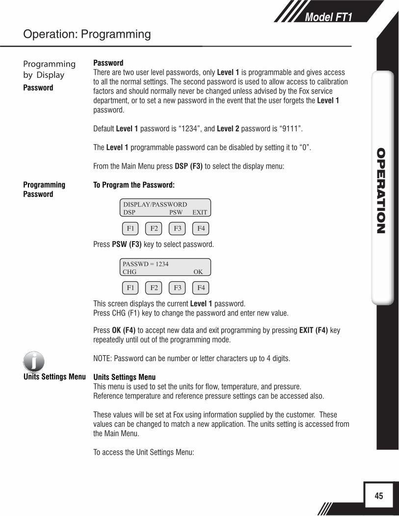
PasswordThere are two user level passwords, only Level 1 is programmable and gives access to all the normal settings. The second password is used to allow access to calibration factors and should normally never be changed unless advised by the Fox service department, or to set a new password in the event that the user forgets the Level 1 password.
Default Level 1 password is “1234”, and Level 2 password is “9111”.
The Level 1 programmable password can be disabled by setting it to “0”.
From the Main Menu press DSP (F3) to select the display menu:
To Program the Password:
F1 F2 F3 F4
Press PSW (F3) key to select password.
F1 F2 F3 F4
This screen displays the current Level 1 password.Press CHG (F1) key to change the password and enter new value.
Press OK (F4) to accept new data and exit programming by pressing EXIT (F4) key repeatedly until out of the programming mode.
NOTE: Password can be number or letter characters up to 4 digits.
Units Settings MenuThis menu is used to set the units for flow, temperature, and pressure.Reference temperature and reference pressure settings can be accessed also.
These values will be set at Fox using information supplied by the customer. These values can be changed to match a new application. The units setting is accessed from the Main Menu.
To access the Unit Settings Menu:
45
Model FT1O
PER
ATIO
NOperation: Programming
Programming by Display
DISPLAY/PASSWORDDSP PSW EXIT
PASSWD = 1234CHG OK
i
F1 F2 F3 F4
Press FLO (F2):
F1 F2 F3 F4
Press UNT (F2) for Unit selection.
The screen will show:
F1 F2 F3 F4
Press NXT (F1) to change selection and OK (F4) to accept.
NOTE: The totalizer (total flow measured) will roll over when reaching a certain value. The maximum value is dependent on the flow units selected (see Totalizer Rollover p. 52).
Selections for flow units are:
SCFM LBS/M MSCFD (MCFD)
SCFH LBS/S SM3/H
NM3/H NLPH MT/H
NM3/M NLPM NM3/D
KG/H MMSCFD (MMCFD) MMSCFM (MMCFM)
KG/M LBS/D SCFD
KG/S SLPM MCFD (MSCFD)
LBS/H NLPS SM3/M
SM3/D
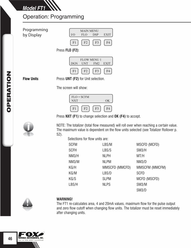
WARNING!The FT1 re-calculates area, 4 and 20mA values, maximum flow for the pulse output and zero flow cutoff when changing flow units. The totalizer must be reset immediately after changing units.
46
Model FT1O
PER
ATIO
N
Operation: Programming
Programming by Display
MAIN MENUI/O FLO DSP EXIT
FLOW MENU 1DGN UNT FM2 EXIT
FLO = SCFMNXT OK
Flow Units
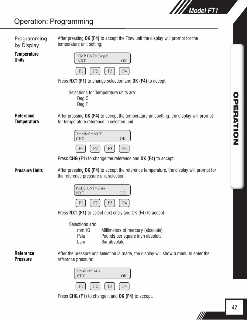
After pressing OK (F4) to accept the Flow unit the display will prompt for the temperature unit setting:
F1 F2 F3 F4
Press NXT (F1) to change selection and OK (F4) to accept.
Selections for Temperature units are: Deg CDeg F
After pressing OK (F4) to accept the temperature unit setting, the display will prompt for temperature reference in selected unit.
F1 F2 F3 F4
Press CHG (F1) to change the reference and OK (F4) to accept.
After pressing OK (F4) to accept the reference temperature, the display will prompt for the reference pressure unit selection:
F1 F2 F3 F4
Press NXT (F1) to select next entry and OK (F4) to accept.
Selections are: mmHG Millimeters of mercury (absolute)Psia Pounds per square inch absolutebara Bar absolute
After the pressure unit selection is made, the display will show a menu to enter the reference pressure:
F1 F2 F3 F4
Press CHG (F1) to change it and OK (F4) to accept.
47
Model FT1O
PER
ATIO
N
Operation: Programming
Programming by Display
TMP UNT= Deg FNXT OK
TmpRef = 60 °FCHG OK
PRES UNT= PsiaNXT OK
Temperature Units
Reference Temperature
Pressure Units
PresRef= 14.7CHG OK
Reference Pressure
Flow Parameters
i
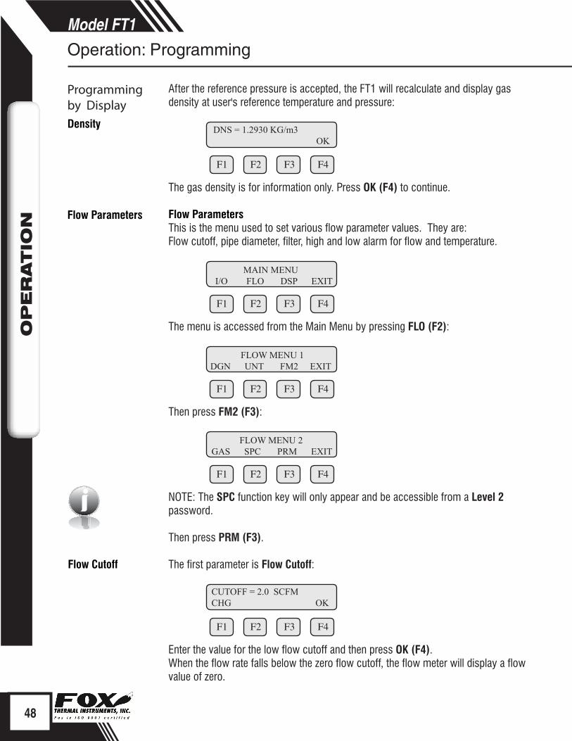
After the reference pressure is accepted, the FT1 will recalculate and display gas density at user's reference temperature and pressure:
F1 F2 F3 F4
The gas density is for information only. Press OK (F4) to continue.
Flow ParametersThis is the menu used to set various flow parameter values. They are:Flow cutoff, pipe diameter, filter, high and low alarm for flow and temperature.
F1 F2 F3 F4
The menu is accessed from the Main Menu by pressing FLO (F2):
F1 F2 F3 F4
Then press FM2 (F3):
F1 F2 F3 F4
NOTE: The SPC function key will only appear and be accessible from a Level 2 password.
Then press PRM (F3).
The first parameter is Flow Cutoff:
F1 F2 F3 F4
Enter the value for the low flow cutoff and then press OK (F4).When the flow rate falls below the zero flow cutoff, the flow meter will display a flow value of zero.
48
Model FT1O
PER
ATIO
N
Operation: Programming
Programming by Display
DNS = 1.2930 KG/m3 OK
MAIN MENU I/O FLO DSP EXIT
FLOW MENU 1DGN UNT FM2 EXIT
FLOW MENU 2GAS SPC PRM EXIT
Density
CUTOFF = 2.0 SCFMCHG OK
Flow Cutoff
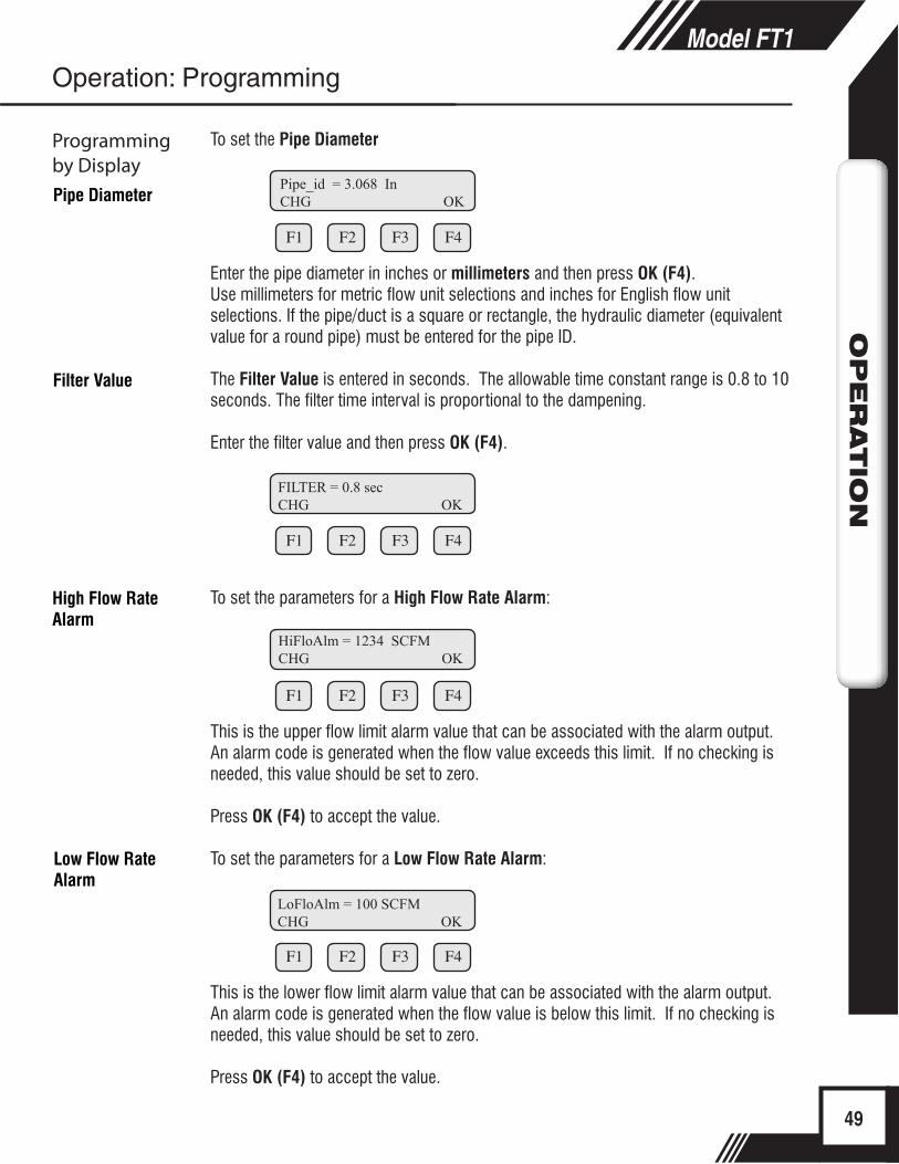
To set the Pipe Diameter
F1 F2 F3 F4
Enter the pipe diameter in inches or millimeters and then press OK (F4).Use millimeters for metric flow unit selections and inches for English flow unit selections. If the pipe/duct is a square or rectangle, the hydraulic diameter (equivalent value for a round pipe) must be entered for the pipe ID.
The Filter Value is entered in seconds. The allowable time constant range is 0.8 to 10 seconds. The filter time interval is proportional to the dampening.
Enter the filter value and then press OK (F4).
F1 F2 F3 F4
To set the parameters for a High Flow Rate Alarm:
F1 F2 F3 F4
This is the upper flow limit alarm value that can be associated with the alarm output. An alarm code is generated when the flow value exceeds this limit. If no checking is needed, this value should be set to zero.
Press OK (F4) to accept the value.
To set the parameters for a Low Flow Rate Alarm:
F1 F2 F3 F4
This is the lower flow limit alarm value that can be associated with the alarm output. An alarm code is generated when the flow value is below this limit. If no checking is needed, this value should be set to zero.
Press OK (F4) to accept the value.
49
Model FT1O
PER
ATIO
N
Operation: Programming
Programming by Display
Pipe_id = 3.068 InCHG OK
FILTER = 0.8 secCHG OK
Pipe Diameter
Filter Value
LoFloAlm = 100 SCFMCHG OK
HiFloAlm = 1234 SCFMCHG OK
Low Flow Rate Alarm
High Flow Rate Alarm
K Factor
i
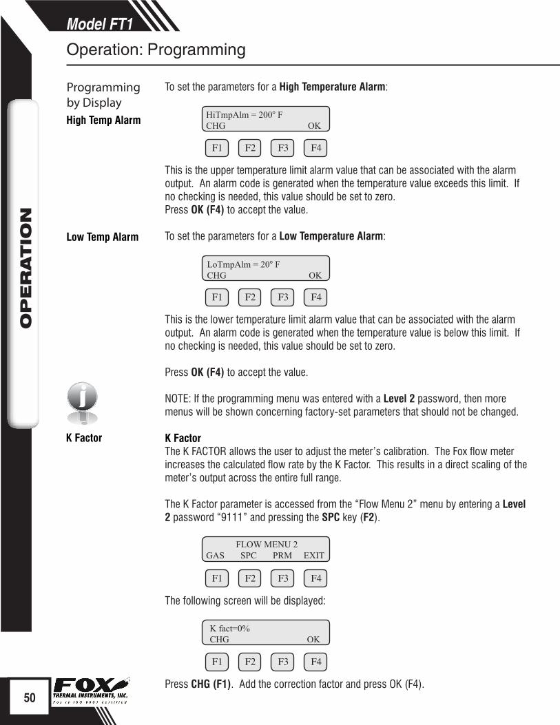
To set the parameters for a High Temperature Alarm:
F1 F2 F3 F4
This is the upper temperature limit alarm value that can be associated with the alarm output. An alarm code is generated when the temperature value exceeds this limit. If no checking is needed, this value should be set to zero.Press OK (F4) to accept the value.
To set the parameters for a Low Temperature Alarm:
F1 F2 F3 F4
This is the lower temperature limit alarm value that can be associated with the alarm output. An alarm code is generated when the temperature value is below this limit. If no checking is needed, this value should be set to zero.
Press OK (F4) to accept the value.
NOTE: If the programming menu was entered with a Level 2 password, then more menus will be shown concerning factory-set parameters that should not be changed. K FactorThe K FACTOR allows the user to adjust the meter’s calibration. The Fox flow meter increases the calculated flow rate by the K Factor. This results in a direct scaling of the meter’s output across the entire full range.
The K Factor parameter is accessed from the “Flow Menu 2” menu by entering a Level 2 password “9111” and pressing the SPC key (F2).
F1 F2 F3 F4
The following screen will be displayed:
F1 F2 F3 F4
Press CHG (F1). Add the correction factor and press OK (F4).50
Model FT1O
PER
ATIO
N
Operation: Programming
Programming by DisplayHigh Temp Alarm HiTmpAlm = 200° F
CHG OK
Low Temp Alarm
LoTmpAlm = 20° FCHG OK
FLOW MENU 2GAS SPC PRM EXIT
K fact=0%CHG OK
Restore Database
Non-Resettable Totalizer
Reset CRC
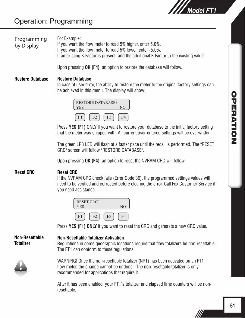
For Example:If you want the flow meter to read 5% higher, enter 5.0%.If you want the flow meter to read 5% lower, enter -5.0%.If an existing K Factor is present, add the additional K Factor to the existing value.
Upon pressing OK (F4), an option to restore the database will follow.
Restore DatabaseIn case of user error, the ability to restore the meter to the original factory settings can be achieved in this menu. The display will show:
F1 F2 F3 F4
Press YES (F1) ONLY if you want to restore your database to the initial factory settingthat the meter was shipped with. All current user-entered settings will be overwritten.
The green LP3 LED will flash at a faster pace until the recall is performed. The "RESETCRC" screen will follow "RESTORE DATABASE".
Upon pressing OK (F4), an option to reset the NVRAM CRC will follow.
Reset CRCIf the NVRAM CRC check fails (Error Code 36), the programmed settings values will need to be verified and corrected before clearing the error. Call Fox Customer Service if you need assistance.
F1 F2 F3 F4
Press YES (F1) ONLY if you want to reset the CRC and generate a new CRC value.
Non-Resettable Totalizer ActivationRegulations in some geographic locations require that flow totalizers be non-resettable. The FT1 can conform to these regulations.
WARNING! Once the non-resettable totalizer (NRT) has been activated on an FT1 flow meter, the change cannot be undone. The non-resettable totalizer is only recommended for applications that require it.
After it has been enabled, your FT1’s totalizer and elapsed time counters will be non-resettable.
51
Model FT1O
PER
ATIO
N
Operation: Programming
Programming by Display
RESTORE DATABASE?YES NO
RESET CRC?YES NO
Simulation
iTotalizer Rollover
Reset Total
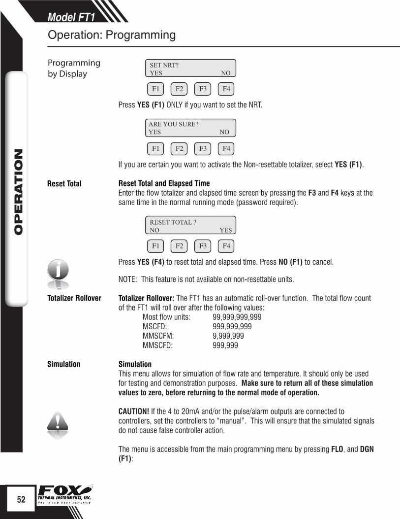
F1 F2 F3 F4
Press YES (F1) ONLY if you want to set the NRT.
F1 F2 F3 F4
If you are certain you want to activate the Non-resettable totalizer, select YES (F1).
Reset Total and Elapsed Time Enter the flow totalizer and elapsed time screen by pressing the F3 and F4 keys at the same time in the normal running mode (password required).
F1 F2 F3 F4
Press YES (F4) to reset total and elapsed time. Press NO (F1) to cancel.
NOTE: This feature is not available on non-resettable units.
Totalizer Rollover: The FT1 has an automatic roll-over function. The total flow count of the FT1 will roll over after the following values:
Most flow units: 99,999,999,999MSCFD: 999,999,999MMSCFM: 9,999,999MMSCFD: 999,999
SimulationThis menu allows for simulation of flow rate and temperature. It should only be used for testing and demonstration purposes. Make sure to return all of these simulation values to zero, before returning to the normal mode of operation.
CAUTION! If the 4 to 20mA and/or the pulse/alarm outputs are connected to controllers, set the controllers to “manual”. This will ensure that the simulated signals do not cause false controller action.
The menu is accessible from the main programming menu by pressing FLO, and DGN (F1):
RESET TOTAL ?NO YES
52
Model FT1O
PER
ATIO
N
Operation: Programming
Programming by Display
ARE YOU SURE?YES NO
SET NRT?YES NO
i
i
i
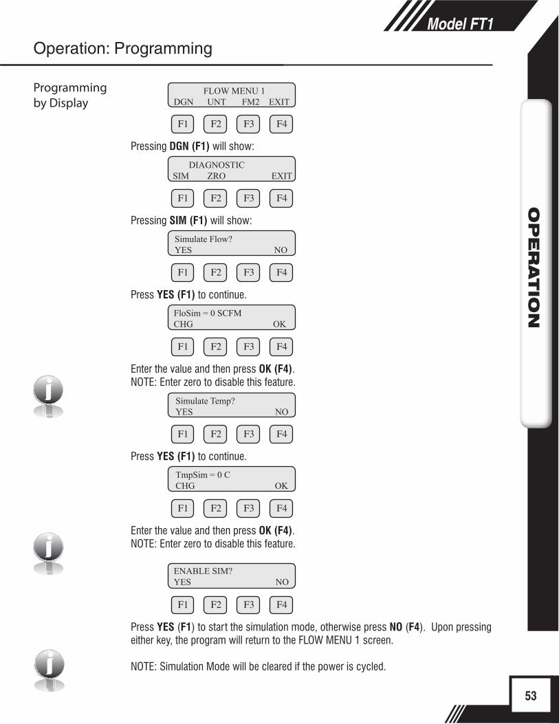
F1 F2 F3 F4
Pressing DGN (F1) will show:
F1 F2 F3 F4
Pressing SIM (F1) will show:
F1 F2 F3 F4
Press YES (F1) to continue.
F1 F2 F3 F4
Enter the value and then press OK (F4).NOTE: Enter zero to disable this feature.
F1 F2 F3 F4
Press YES (F1) to continue.
F1 F2 F3 F4
Enter the value and then press OK (F4).NOTE: Enter zero to disable this feature.
F1 F2 F3 F4
Press YES (F1) to start the simulation mode, otherwise press NO (F4). Upon pressing either key, the program will return to the FLOW MENU 1 screen.
NOTE: Simulation Mode will be cleared if the power is cycled.
53
Model FT1O
PER
ATIO
N
FLOW MENU 1DGN UNT FM2 EXIT
Operation: Programming
Programming by Display
DIAGNOSTICSIM ZRO EXIT
FloSim = 0 SCFMCHG OK
TmpSim = 0 CCHG OK
ENABLE SIM?YES NO
Simulate Flow?YES NO
Simulate Temp?YES NO
i
54
Model FT1O
PER
ATIO
N
Operation: Zero CAL-CHECK®
Calibration of the Fox Model FT1 Thermal Flow MeterTo ensure that all Fox flow meters meet specified performance parameters and provide accurate, repeatable measurements in the field, all calibrations are performed with NIST-traceable flow standards. Each meter is shipped from the factory with a Fox Calibration Certificate.
Calibration ValidationCalibration Validation allows our customers to validate the accuracy and functionality of the meter in the field with a push of a button. By performing a simple test, the operator can verify that the meter is running accurately.
Zero CAL-CHECK® ensures the repeatability, functionality of the sensor and its associated signal processing circuitry, and cleanliness of the sensor.
Fox has developed the Zero CAL-CHECK® Calibration Validation to help our customers avoid sending the meter back for annual or biennial re-calibrations.
Zero CAL-CHECK® Calibration Validation Test The Zero CAL-CHECK® test is used to ensure that the flow meter still retains its original NIST-traceable calibration at zero flow. If zero flow can be established, the sensor does not need to be removed and the procedure can be done in the pipe. Alternatively, a clean, dry bottle can be used to create a “no flow” condition out of the pipe.
NOTE: If the Zero CAL-CHECK® test is performed using the Fox FT1 View™ Software, at the completion of the test, a Zero CAL-CHECK® Certificate may be printed for a record of the test. This certificate will display a pass/fail result.
Calibration
Calibration Validation
Zero CAL-CHECK®
55
Model FT1O
PER
ATIO
N
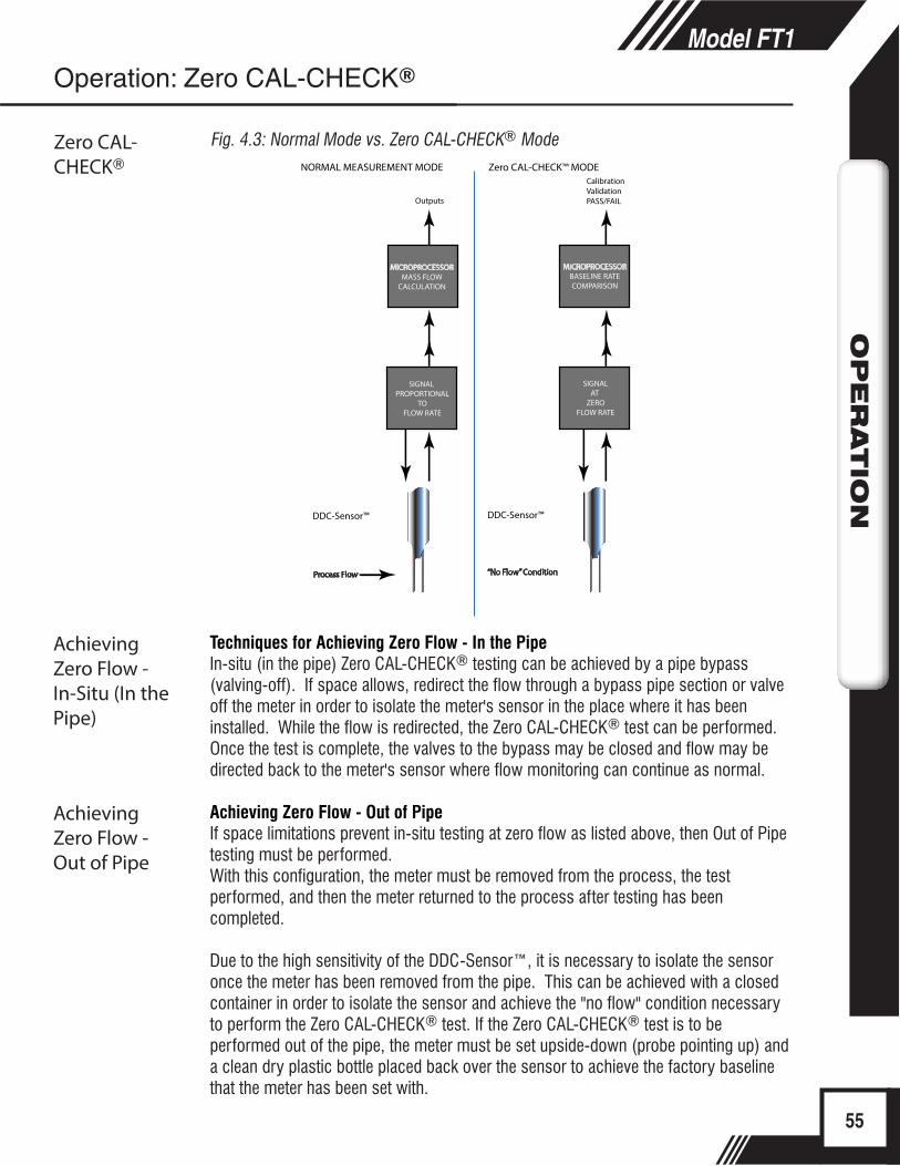
Fig. 4.3: Normal Mode vs. Zero CAL-CHECK® Mode
SIGNAL PROPORTIONAL
TOFLOW RATE
MICROPROCESSORMASS FLOW
CALCULATION
NORMAL MEASUREMENT MODE
DDC-Sensor™
Outputs
Zero CAL-CHECK™ MODECalibration ValidationPASS/FAIL
MICROPROCESSORBASELINE RATECOMPARISON
SIGNALAT
ZEROFLOW RATE
DDC-Sensor™
Process Flow “No Flow” Condition
Zero CAL-CHECK®
Operation: Zero CAL-CHECK®
Techniques for Achieving Zero Flow - In the PipeIn-situ (in the pipe) Zero CAL-CHECK® testing can be achieved by a pipe bypass (valving-off). If space allows, redirect the flow through a bypass pipe section or valve off the meter in order to isolate the meter's sensor in the place where it has been installed. While the flow is redirected, the Zero CAL-CHECK® test can be performed. Once the test is complete, the valves to the bypass may be closed and flow may be directed back to the meter's sensor where flow monitoring can continue as normal.
Achieving Zero Flow - Out of PipeIf space limitations prevent in-situ testing at zero flow as listed above, then Out of Pipe testing must be performed.With this configuration, the meter must be removed from the process, the test performed, and then the meter returned to the process after testing has been completed.
Due to the high sensitivity of the DDC-Sensor™, it is necessary to isolate the sensor once the meter has been removed from the pipe. This can be achieved with a closed container in order to isolate the sensor and achieve the "no flow" condition necessary to perform the Zero CAL-CHECK® test. If the Zero CAL-CHECK® test is to be performed out of the pipe, the meter must be set upside-down (probe pointing up) and a clean dry plastic bottle placed back over the sensor to achieve the factory baseline that the meter has been set with.
Achieving Zero Flow - In-Situ (In the Pipe)
Achieving Zero Flow - Out of Pipe
56
Model FT1O
PER
ATIO
N
i
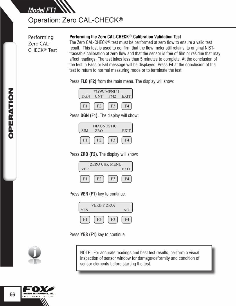
Performing the Zero CAL-CHECK® Calibration Validation Test The Zero CAL-CHECK® test must be performed at zero flow to ensure a valid test result. This test is used to confirm that the flow meter still retains its original NIST-traceable calibration at zero flow and that the sensor is free of film or residue that may affect readings. The test takes less than 5 minutes to complete. At the conclusion of the test, a Pass or Fail message will be displayed. Press F4 at the conclusion of the test to return to normal measuring mode or to terminate the test. Press FLO (F2) from the main menu. The display will show:
F1 F2 F3 F4
Press DGN (F1). The display will show:
F1 F2 F3 F4
Press ZRO (F2). The display will show:
F1 F2 F3 F4
Press VER (F1) key to continue.
F1 F2 F3 F4
Press YES (F1) key to continue.
NOTE: For accurate readings and best test results, perform a visual inspection of sensor window for damage/deformity and condition of sensor elements before starting the test.
Performing Zero CAL-CHECK® Test
FLOW MENU 1 DGN UNT FM2 EXIT
DIAGNOSTICSIM ZRO EXIT
ZERO CHK MENU VER EXIT
Operation: Zero CAL-CHECK®
VERIFY ZRO?YES NO
Performing Zero CAL-CHECK® Test

57
Model FT1O
PER
ATIO
N
F1 F2 F3 F4
WARNING! You must ensure that there is a no flow condition before proceeding. If you are performing the test in a bottle, be sure to isolate the sensor in a closed container - any air movement (even from a fan) may result in a false "fail" result.
Once process is stable, press YES (F3) key to begin the Zero CAL-CHECK®.
F1 F2 F3 F4
This test will take less than 5 minutes. The T=xx is a count down timer indicating how much time is left to finish the test.
F1 F2 F3 F4
OR F1 F2 F3 F4
OR
F1 F2 F3 F4
Upon test completion, the final value will be displayed along with the test result. The test result may be:• Pass: less than ±0.80• Warning: between ±0.80 to ±1.0• Fail: greater than ±1.0
If a "Warning" or "Fail" result is displayed, Fox recommends that the probe be removed from the pipe, the sensor cleaned, and the test be performed again. If the test was performed in the pipe the first time, perform the test in a bottle for the re-test.
If a "Warning" or "Fail" result is displayed after performing the test a second time, please call Fox Service at (831) 384-4300 for assistance.
Verifying ZROy.yyy T=xx
ZRO=2.321Fail OK
Process Zero and Stable? YES EXIT
Operation: Zero CAL-CHECK®
Performing Zero CAL-CHECK® Test
ZRO=0.911Warning OK
ZRO=0.259Pass OK

ii
Accessing the Gas-SelectX® Gas Selection Menu FeatureThis menu allows the user to select a gas or gas mix from a pre-calibrated list of gases/gas mixtures available on the Fox Model FT1 Flowmeter. Gases and gas mixes available in the Gas-SelectX® feature include:
• Methane• Carbon Dioxide (CO2)• Nitrogen• Air• Natural Gas*• Argon• Propane• Helium• Oxygen• Butane• Hydrogen• Gas Mix**
*Natural gas refers to pipeline-quality dry natural gas, whereas naturally occurring gas from oil fields constitutes a special mixed gas requiring a special calibration. Natural Gas is not available in the 3-Gas Mix feature. Contact Fox for further information.
**The molar mass of the gas mixes are programmable in 0.1% increments. Any three gases available in the Gas-SelectX® menu may be used in any proportion equaling 100%
NOTE: For the latest gas and gas mix menu, visit the Fox Website: www.foxthermalinstruments.com
After installing your FT1 flowmeter, power up the device. When the meter finishes initializing, it will begin to monitor flow in the gas and flow units assigned at the factory.
The display will show the information similar to the example below. Follow these instructions to access the Gas-SelectX® feature:
F1 F2 F3 F4
To enter the programming mode from the normal monitoring mode and access the Gas-SelectX® menu, press the F1 or F2 key repeatedly until the following screen is shown:
58
Model FT1O
PER
ATIO
N
Operation: Gas-SelectX®
1162.52 SCFMTot=6205012.50 SCF
Accessing Gas-SelectX® Menu
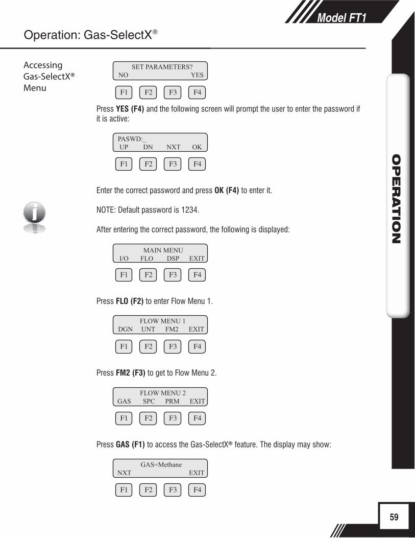
i
F1 F2 F3 F4
Press YES (F4) and the following screen will prompt the user to enter the password if it is active:
F1 F2 F3 F4
Enter the correct password and press OK (F4) to enter it.
NOTE: Default password is 1234.
After entering the correct password, the following is displayed:
F1 F2 F3 F4
Press FLO (F2) to enter Flow Menu 1.
F1 F2 F3 F4
Press FM2 (F3) to get to Flow Menu 2.
F1 F2 F3 F4
Press GAS (F1) to access the Gas-SelectX® feature. The display may show:
F1 F2 F3 F4
59
Model FT1O
PER
ATIO
NOperation: Gas-SelectX®
PASWD:_ UP DN NXT OK
MAIN MENU I/O FLO DSP EXIT
FLOW MENU 1 DGN UNT FM2 EXIT
FLOW MENU 2 GAS SPC PRM EXIT
GAS=Methane NXT EXIT
Accessing Gas-SelectX® Menu
SET PARAMETERS? NO YES

From this screen, the user will be able to access two aspects of the Gas-SelectX® menu:1. Pure Gas = Choosing from a list of available gases, or 2. Gas Mix = Programming a specific mixture of three gases
Choosing a Gas from the Gas-SelectX® MenuThe Gas-SelectX® menu will show one of the available gases/gas mixtures:
F1 F2 F3 F4
Press NXT (F1) to choose from a list of gases. Choices are:• Methane• CO2 = Carbon Dioxide• Nitrogen• Air• Natural Gas (*see definition p. 58)• Argon• Propane• Helium• Oxygen• Butane• Hydrogen• Gas Mix = Mix of any three gases above; proportions must equal 100%
To choose any pure gas, cycle through until the correct gas is displayed and press OK (F4) to choose the gas.
To create a gas mix, choose %Mix from the list and press OK (F4).
F1 F2 F3 F4
The screen will show:
F1 F2 F3 F4
This screen shows the percentage of the gas mixture allocated to Air. In this case, it shows 0%. To program the specific mixture of Methane, press CHG (F1).
60
Model FT1O
PER
ATIO
NOperation: Gas-SelectX®
GAS=Air NXT EXIT
GAS= %Mix NXT OK
Methane=0% CHG OK
Choosing a Gas
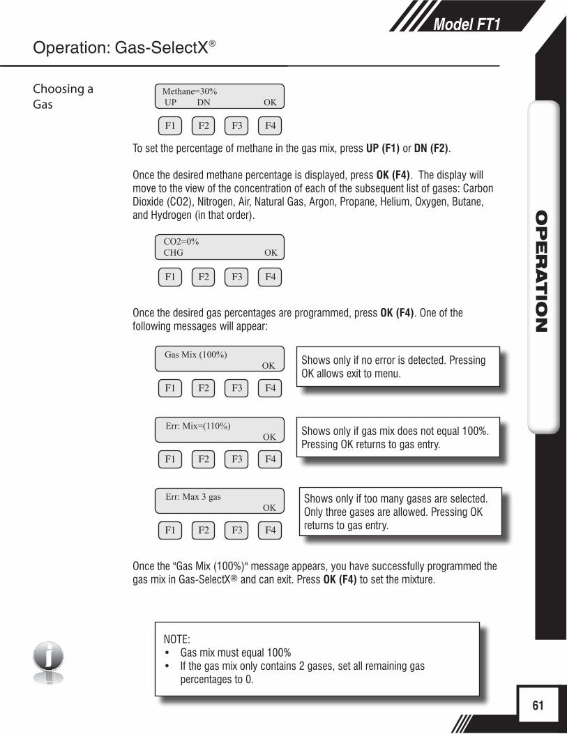
i
F1 F2 F3 F4
To set the percentage of methane in the gas mix, press UP (F1) or DN (F2).
Once the desired methane percentage is displayed, press OK (F4). The display will move to the view of the concentration of each of the subsequent list of gases: Carbon Dioxide (CO2), Nitrogen, Air, Natural Gas, Argon, Propane, Helium, Oxygen, Butane, and Hydrogen (in that order).
F1 F2 F3 F4
Once the desired gas percentages are programmed, press OK (F4). One of the following messages will appear:
F1 F2 F3 F4
F1 F2 F3 F4
F1 F2 F3 F4
Once the "Gas Mix (100%)" message appears, you have successfully programmed the gas mix in Gas-SelectX® and can exit. Press OK (F4) to set the mixture.
61
Model FT1O
PER
ATIO
N
Methane=30% UP DN OK
Operation: Gas-SelectX®
CO2=0% CHG OK
Gas Mix (100%) OK
Err: Mix=(110%) OK
Err: Max 3 gas OK
Choosing a Gas
NOTE: • Gas mix must equal 100%• If the gas mix only contains 2 gases, set all remaining gas
percentages to 0.
Shows only if no error is detected. Pressing OK allows exit to menu.
Shows only if gas mix does not equal 100%. Pressing OK returns to gas entry.
Shows only if too many gases are selected. Only three gases are allowed. Pressing OK returns to gas entry.

The FT1 will begin to monitor flow based on the pre-calibrated algorithm for the gas selected in the Gas-SelectX® feature. The screen will show the flow in units and the total flow similar to the example below:
F1 F2 F3 F4
From normal operating mode, the gas selection can be seen on display 3 (see p. 37).
62
Model FT1O
PER
ATIO
NOperation: Gas-SelectX®
1162.52 SCFM6205012.50 SCF
Choosing a Gas
Modbus Introduction
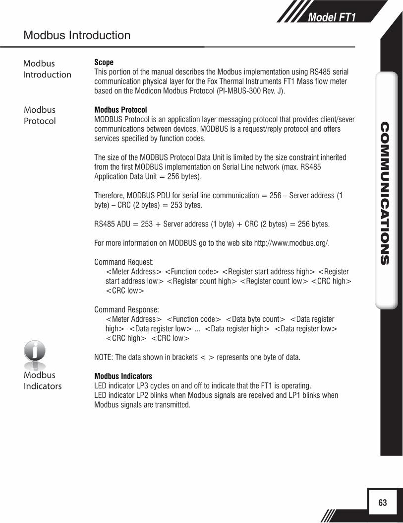
63
Model FT1C
OM
MU
NIC
ATIO
NS
i
ScopeThis portion of the manual describes the Modbus implementation using RS485 serial communication physical layer for the Fox Thermal Instruments FT1 Mass flow meter based on the Modicon Modbus Protocol (PI-MBUS-300 Rev. J).
Modbus ProtocolMODBUS Protocol is an application layer messaging protocol that provides client/sever communications between devices. MODBUS is a request/reply protocol and offers services specified by function codes.
The size of the MODBUS Protocol Data Unit is limited by the size constraint inherited from the first MODBUS implementation on Serial Line network (max. RS485 Application Data Unit = 256 bytes).
Therefore, MODBUS PDU for serial line communication = 256 – Server address (1 byte) – CRC (2 bytes) = 253 bytes.
RS485 ADU = 253 + Server address (1 byte) + CRC (2 bytes) = 256 bytes.
For more information on MODBUS go to the web site http://www.modbus.org/.
Command Request:<Meter Address> <Function code> <Register start address high> <Register start address low> <Register count high> <Register count low> <CRC high> <CRC low>
Command Response:<Meter Address> <Function code> <Data byte count> <Data register high> <Data register low> ... <Data register high> <Data register low> <CRC high> <CRC low>
NOTE: The data shown in brackets < > represents one byte of data.
Modbus IndicatorsLED indicator LP3 cycles on and off to indicate that the FT1 is operating. LED indicator LP2 blinks when Modbus signals are received and LP1 blinks when Modbus signals are transmitted.
Modbus Introduction
Modbus Introduction
Modbus Protocol
Modbus Indicators

64
Model FT1C
OM
MU
NIC
ATIO
NS
Model FT1C
OM
MU
NIC
ATIO
NS
FT1 Commands SupportedThe FT1 supports the following commands:
1) Command 03: Read holding registers2) Command 04: Read input register.3) Command 06: Preset single register
Read Holding Registers (command 03)This command reads the basic variable from the FT1 and has the following format:
Request:<Meter Address> <Command code=03> <Register start address high> <Register start address low> <Register count high> <Register count low> <CRC high> <CRC low>
Response:<Meter Address> <Command code=03> <Byte count> <Data high><Data low> ... <Data high><Data low> <CRC high> <CRC low>
Example:Request data register at starting address 0x0000 and specifying only 1 register
<0x01> <0x03> <0x00> <0x00> <0x00> <0x01> <0x0a> <0x84>
Response:<0x01> <0x03> <0x02> <xx> <xx> <CRC high> <CRC low>
Where xx xx is the data register value.
Table 5.1: FT1 Modbus Holding Registers
Register Address
Modbus Address
Data Type Scaling Comment
0x00 40001 Flow in Eng units (low) No Mass flow in selected units
0x01 40002 Flow in Eng units (high) No
0x02 40003 Total (low) No Total in selected units
0x03 40004 Total (High) No
0x04 40005 Temperature (low) *10 Temperature in selected units * 10
0x05 40006 Temperature (high) *10
0x06 40007 Elapsed time (low) *10 Elapsed time in hours * 10
0x07 40008 Elapsed time (high) *10
0x08 40009 Spare/not used
0x09 40010 Spare/not used
0x0A 40011 Flow in Eng units * 10 10 Mass flow in selected units * 10
0x0B 40012 Flow in Eng units *100 100 Mass flow in selected units * 100
0x0C 40013 Total *100 100 Total in selected units * 100
FT1 Commands Supported by Modbus
FT1 Commands Supported
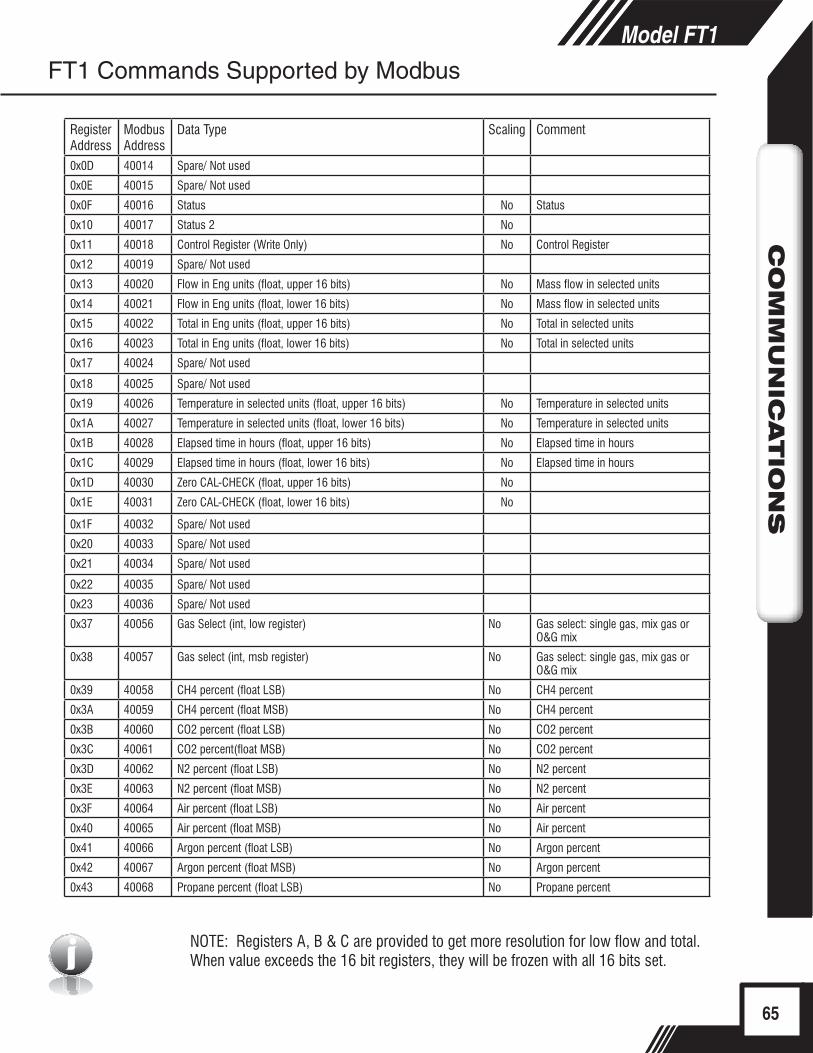
i65
Model FT1C
OM
MU
NIC
ATIO
NS
Model FT1C
OM
MU
NIC
ATIO
NS
Register Address
Modbus Address
Data Type Scaling Comment
0x0D 40014 Spare/ Not used
0x0E 40015 Spare/ Not used
0x0F 40016 Status No Status
0x10 40017 Status 2 No
0x11 40018 Control Register (Write Only) No Control Register
0x12 40019 Spare/ Not used
0x13 40020 Flow in Eng units (float, upper 16 bits) No Mass flow in selected units
0x14 40021 Flow in Eng units (float, lower 16 bits) No Mass flow in selected units
0x15 40022 Total in Eng units (float, upper 16 bits) No Total in selected units
0x16 40023 Total in Eng units (float, lower 16 bits) No Total in selected units
0x17 40024 Spare/ Not used
0x18 40025 Spare/ Not used
0x19 40026 Temperature in selected units (float, upper 16 bits) No Temperature in selected units
0x1A 40027 Temperature in selected units (float, lower 16 bits) No Temperature in selected units
0x1B 40028 Elapsed time in hours (float, upper 16 bits) No Elapsed time in hours
0x1C 40029 Elapsed time in hours (float, lower 16 bits) No Elapsed time in hours
0x1D 40030 Zero CAL-CHECK (float, upper 16 bits) No
0x1E 40031 Zero CAL-CHECK (float, lower 16 bits) No
0x1F 40032 Spare/ Not used
0x20 40033 Spare/ Not used
0x21 40034 Spare/ Not used
0x22 40035 Spare/ Not used
0x23 40036 Spare/ Not used
0x37 40056 Gas Select (int, low register) No Gas select: single gas, mix gas or O&G mix
0x38 40057 Gas select (int, msb register) No Gas select: single gas, mix gas or O&G mix
0x39 40058 CH4 percent (float LSB) No CH4 percent
0x3A 40059 CH4 percent (float MSB) No CH4 percent
0x3B 40060 CO2 percent (float LSB) No CO2 percent
0x3C 40061 CO2 percent(float MSB) No CO2 percent
0x3D 40062 N2 percent (float LSB) No N2 percent
0x3E 40063 N2 percent (float MSB) No N2 percent
0x3F 40064 Air percent (float LSB) No Air percent
0x40 40065 Air percent (float MSB) No Air percent
0x41 40066 Argon percent (float LSB) No Argon percent
0x42 40067 Argon percent (float MSB) No Argon percent
0x43 40068 Propane percent (float LSB) No Propane percent
FT1 Commands Supported by Modbus
NOTE: Registers A, B & C are provided to get more resolution for low flow and total. When value exceeds the 16 bit registers, they will be frozen with all 16 bits set.

66
Model FT1C
OM
MU
NIC
ATIO
NS
Model FT1Model FT1C
OM
MU
NIC
ATIO
NS
Read Input Register (FT1 Status, Command 04)This command is used to report the FT1 status information.
Request:<Meter Address> <Command code=04> <Register address =0> <Register address =0> <Register count =0> <Register count =1> <CRC high> <CRC low>
Response:<Meter Address> <Command code=04> <Byte count =2> <Status High><Status Low> <CRC high> <CRC low>
Table 5.2: Status Bits Definitions for Command 04, Modbus Address 30001
FT1 Commands Supported by Modbus
Read Input Register
Bit Definition Comment0 Power up indication Cleared when out of the power up sequence
1 Flow rate reached high limit threshold Set limit to zero to disable
2 Flow rate reached low limit threshold Set limit to zero to disable
3 Temperature reached high limit threshold Set limit to zero to disable
4 Temperature reached low limit threshold Set limit to zero to disable
5 Sensor reading is out of range Check sensor wiring
6 Gas mix error Gas mix must total 100%
7 Incorrect Settings Check settings
8 In simulation mode Set simulation value to 0 to disable
9 Pulse/alarm output is out of range Check pulse/alarm output settings
10 Analog 4-20 mA for flow/temp is out of range Check analog output settings
11 Not used Not used
12 Not used Not used
13 Not used Not used
14 CRC error Check parameters and reset CRC
15 Error in Total Reset total to clear alarm
Register Address
Modbus Address
Data Type Scaling Comment
0x44 40069 Propane percent (float MSB) No Propane percent
0x45 40070 Helium percent (float LSB) No Helium percent
0x46 40071 Helium percent (float MSB) No Helium percent
0x47 40072 Oxygen percent (float LSB) No Oxygen percent
0x48 40073 Oxygen percent (float MSB) No Oxygen percent
0x49 40074 Butane percent (float LSB) No Butane percent
0x4A 40075 Butane percent (float MSB) No Butane percent
0x4B 40076 Hydrogen percent (float LSB) No Hydrogen percent
0x4C 40077 Hydrogen percent (float MSB) No Hydrogen percent
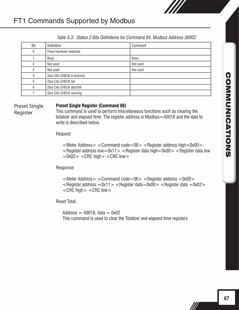
67
Model FT1C
OM
MU
NIC
ATIO
NS
CO
MM
UN
ICATIO
NS
Table 5.3: Status 2 Bits Definitions for Command 04, Modbus Address 30002
Bit Definition Comment0 Pulse hardware detected
1 Busy Busy
2 Not used Not used
3 Not used Not used
4 Zero CAL-CHECK in process
5 Zero CAL-CHECK fail
6 Zero CAL-CHECK aborted
7 Zero CAL-CHECK warning
FT1 Commands Supported by Modbus
Preset Single Register
Preset Single Register (Command 06)This command is used to perform miscellaneous functions such as clearing the totalizer and elapsed time. The register address is Modbus=40018 and the data to write is described below.
Request:
<Meter Address> <Command code=06> <Register address high=0x00> <Register address low=0x11> <Register data high=0x00> <Register data low =0x02> <CRC high> <CRC low>
Response:
<Meter Address> <Command code=06> <Register address =0x00> <Register address =0x11> <Register data=0x00> <Register data =0x02> <CRC high> <CRC low>
Reset Total:
Address = 40018, data = 0x02This command is used to clear the Totalizer and elapsed time registers
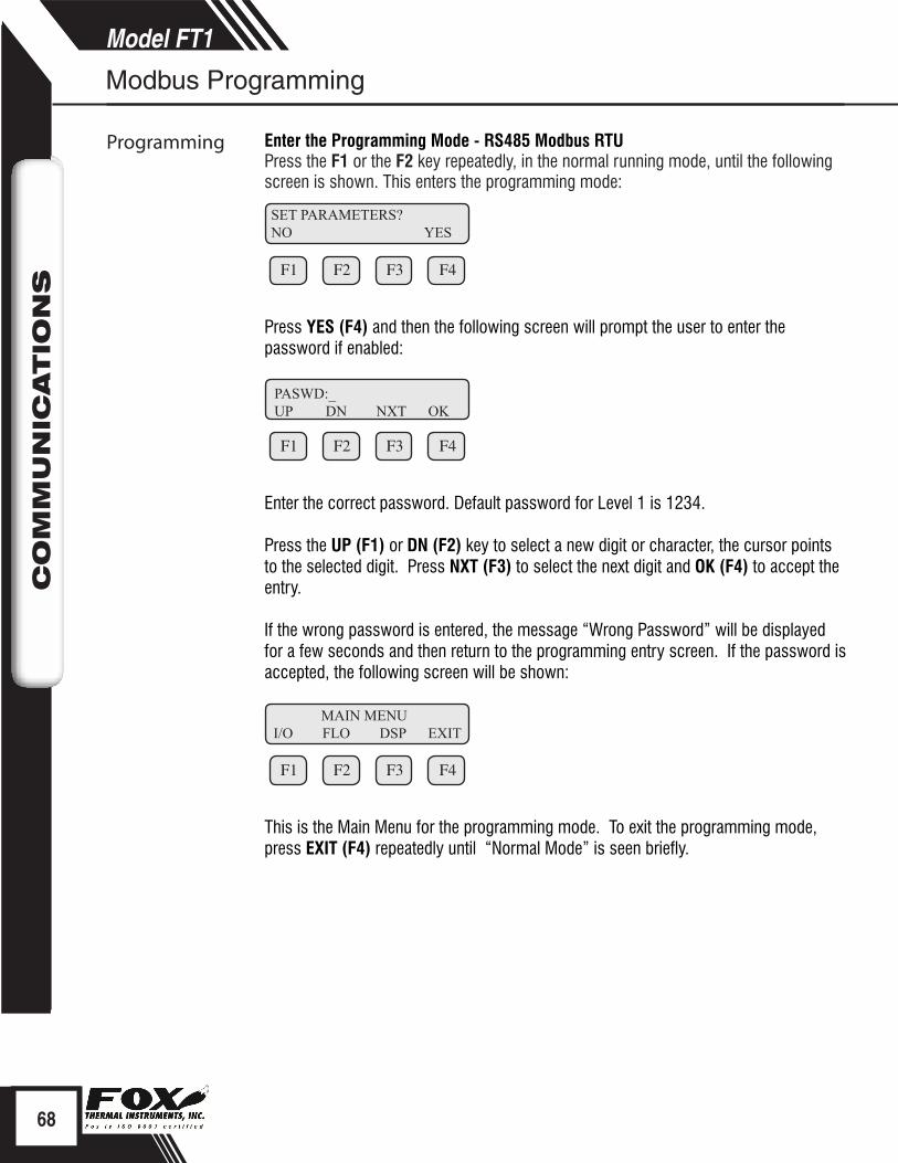
68
Model FT1C
OM
MU
NIC
ATIO
NS
Model FT1C
OM
MU
NIC
ATIO
NS
Enter the Programming Mode - RS485 Modbus RTUPress the F1 or the F2 key repeatedly, in the normal running mode, until the following screen is shown. This enters the programming mode:
F1 F2 F3 F4
Press YES (F4) and then the following screen will prompt the user to enter the password if enabled:
F1 F2 F3 F4
Enter the correct password. Default password for Level 1 is 1234.
Press the UP (F1) or DN (F2) key to select a new digit or character, the cursor points to the selected digit. Press NXT (F3) to select the next digit and OK (F4) to accept the entry. If the wrong password is entered, the message “Wrong Password” will be displayed for a few seconds and then return to the programming entry screen. If the password is accepted, the following screen will be shown:
F1 F2 F3 F4
This is the Main Menu for the programming mode. To exit the programming mode, press EXIT (F4) repeatedly until “Normal Mode” is seen briefly.
Modbus Programming
Programming
SET PARAMETERS?NO YES
PASWD:_UP DN NXT OK
MAIN MENUI/O FLO DSP EXIT
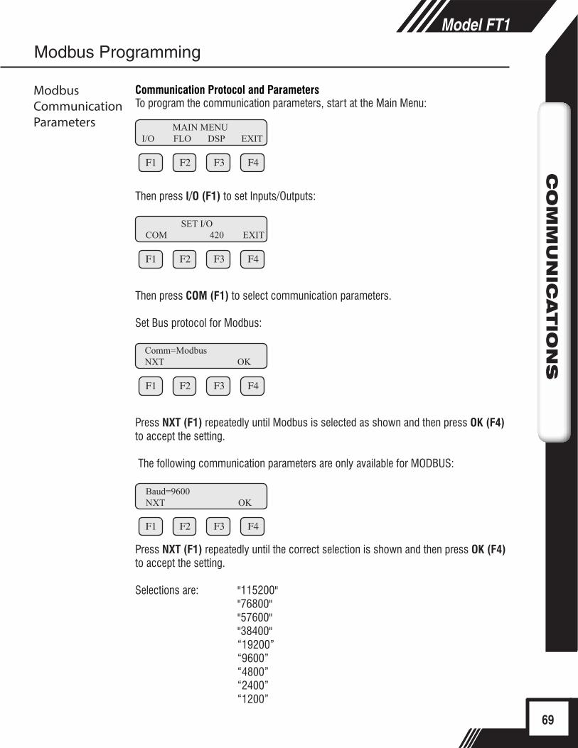
69
Model FT1C
OM
MU
NIC
ATIO
NS
Model FT1C
OM
MU
NIC
ATIO
NS
Modbus Programming
Communication Protocol and ParametersTo program the communication parameters, start at the Main Menu:
F1 F2 F3 F4
Then press I/O (F1) to set Inputs/Outputs:
F1 F2 F3 F4
Then press COM (F1) to select communication parameters.
Set Bus protocol for Modbus:
F1 F2 F3 F4
Press NXT (F1) repeatedly until Modbus is selected as shown and then press OK (F4) to accept the setting.
The following communication parameters are only available for MODBUS:
F1 F2 F3 F4
Press NXT (F1) repeatedly until the correct selection is shown and then press OK (F4) to accept the setting.
Selections are: "115200" "76800" "57600" "38400" “19200” “9600” “4800” “2400” “1200”
Baud=9600NXT OK
SET I/OCOM 420 EXIT
Comm=ModbusNXT OK
ModbusCommunication Parameters MAIN MENU
I/O FLO DSP EXIT
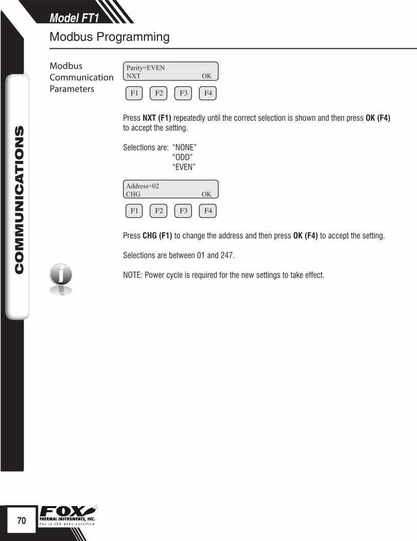
70
Model FT1C
OM
MU
NIC
ATIO
NS
Model FT1C
OM
MU
NIC
ATIO
NS
Modbus Programming
ModbusCommunication Parameters
i
F1 F2 F3 F4
Press NXT (F1) repeatedly until the correct selection is shown and then press OK (F4) to accept the setting.
Selections are: “NONE” “ODD” “EVEN”
F1 F2 F3 F4
Press CHG (F1) to change the address and then press OK (F4) to accept the setting.
Selections are between 01 and 247.
NOTE: Power cycle is required for the new settings to take effect.
Parity=EVENNXT OK
Address=02CHG OK
BACnet Introduction
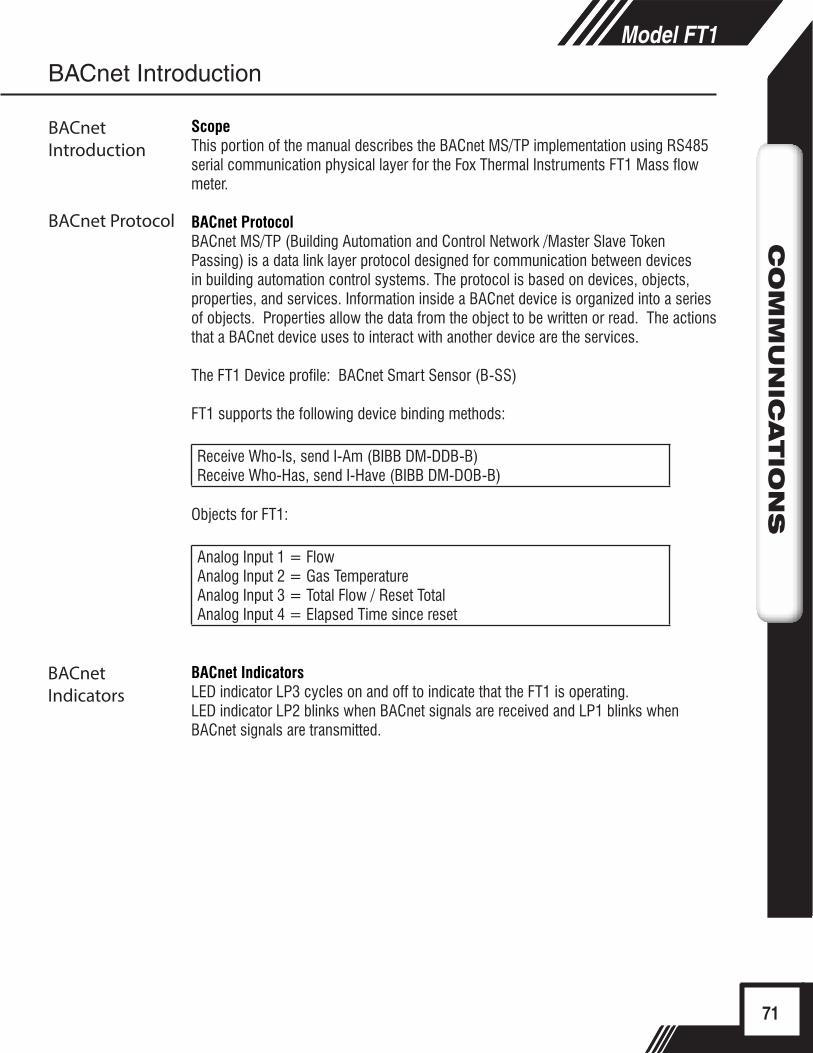
71
Model FT1C
OM
MU
NIC
ATIO
NS
Model FT1C
OM
MU
NIC
ATIO
NS
ScopeThis portion of the manual describes the BACnet MS/TP implementation using RS485 serial communication physical layer for the Fox Thermal Instruments FT1 Mass flow meter.
BACnet ProtocolBACnet MS/TP (Building Automation and Control Network /Master Slave Token Passing) is a data link layer protocol designed for communication between devices in building automation control systems. The protocol is based on devices, objects, properties, and services. Information inside a BACnet device is organized into a series of objects. Properties allow the data from the object to be written or read. The actions that a BACnet device uses to interact with another device are the services.
The FT1 Device profile: BACnet Smart Sensor (B-SS)
FT1 supports the following device binding methods:
Receive Who-Is, send I-Am (BIBB DM-DDB-B)Receive Who-Has, send I-Have (BIBB DM-DOB-B)
Objects for FT1:
Analog Input 1 = FlowAnalog Input 2 = Gas TemperatureAnalog Input 3 = Total Flow / Reset TotalAnalog Input 4 = Elapsed Time since reset
BACnet IndicatorsLED indicator LP3 cycles on and off to indicate that the FT1 is operating. LED indicator LP2 blinks when BACnet signals are received and LP1 blinks when BACnet signals are transmitted.
BACnet Introduction
BACnet Introduction
BACnet Protocol
BACnet Indicators
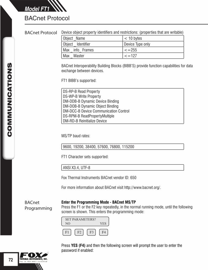
72
Model FT1C
OM
MU
NIC
ATIO
NS
Model FT1C
OM
MU
NIC
ATIO
NS
BACnet Protocol Device object property identifiers and restrictions: (properties that are writable)Object _Name < 10 bytesObject _ Identifier Device Type onlyMax _ info_ Frames <=255Max _ Master <=127
BACnet Interoperability Building Blocks (BIBB’S) provide function capabilities for data exchange between devices.
FT1 BIBB’s supported:
DS-RP-B Read PropertyDS-WP-B Write PropertyDM-DDB-B Dynamic Device BindingDM-DOB-B Dynamic Object BindingDM-DCC-B Device Communication ControlDS-RPM-B ReadPropertyMultipleDM-RD-B Reinitialize Device
MS/TP baud rates:
9600, 19200, 38400, 57600, 76800, 115200
FT1 Character sets supported:
ANSI X3.4, UTF-8
Fox Thermal Instruments BACnet vendor ID: 650
For more information about BACnet visit http://www.bacnet.org/.
Enter the Programming Mode - BACnet MS/TPPress the F1 or the F2 key repeatedly, in the normal running mode, until the following screen is shown. This enters the programming mode:
F1 F2 F3 F4
Press YES (F4) and then the following screen will prompt the user to enter the password if enabled:
BACnet Protocol
BACnet Programming
SET PARAMETERS?NO YES
BACnet Programming

73
Model FT1C
OM
MU
NIC
ATIO
NS
Model FT1C
OM
MU
NIC
ATIO
NS
BACnet Programming
F1 F2 F3 F4
Enter the correct password. Default password for Level 1 is 1234.
Communication Protocol and ParametersTo program the communication parameters, press I/O (F1) key from the main menu.
F1 F2 F3 F4
This is the main menu for the programming mode. To exit the programming mode, press EXIT (F4) repeatedly until “Normal Mode” is seen briefly. Choose I/O (F1) to access the communication output.
F1 F2 F3 F4
Then press COM (F1) to select communication parameters
Set Bus protocol for BACnet:
F1 F2 F3 F4
Press NXT (F1) until BACnet is selected as shown and then press OK (F4) to accept the setting.
F1 F2 F3 F4
Press NXT (F1) repeatedly until the correct selection is shown and then press OK (F4) to accept the setting.Selections are: “9600”
“19200” “38400” “57600” “76800” “115200"
PASWD:_UP DN NXT OK
MAIN MENU I/O FLO DSP EXIT
BACnet Programming
SET I/OCOM 420 EXIT
Comm=BACnetNXT OK
Baud=9600NXT OK
BACnet Communication Parameters

74
Model FT1C
OM
MU
NIC
ATIO
NS
CO
MM
UN
ICATIO
NS
BACnet Programming
BACnet Communication Parameters
Next select the MS/TP Mac address. The selection is from 0-127. Please note that only one device can be on a MS/TP Mac address.
F1 F2 F3 F4
Next select the MS/TP Max Master using CHG (F1). The selection is from 0-127. Press OK (F4) to accept the setting.
F1 F2 F3 F4
Next input the device object instance using CHG (F1). Selection is from 0-4194303. Press OK (F4) to accept the setting.
F1 F2 F3 F4
Next enter the device object name (9 characters maximum) using CHG (F1). Press OK (F4) to accept the setting.
F1 F2 F3 F4
NOTE: Power cycle is required for the new settings to take effect.i
MAC_ADD=23CHG OK
NAME=FT1_FLOWCHG OK
ID=12531CHG OK
MAX_MASTER=127CHG OK
HART Introduction
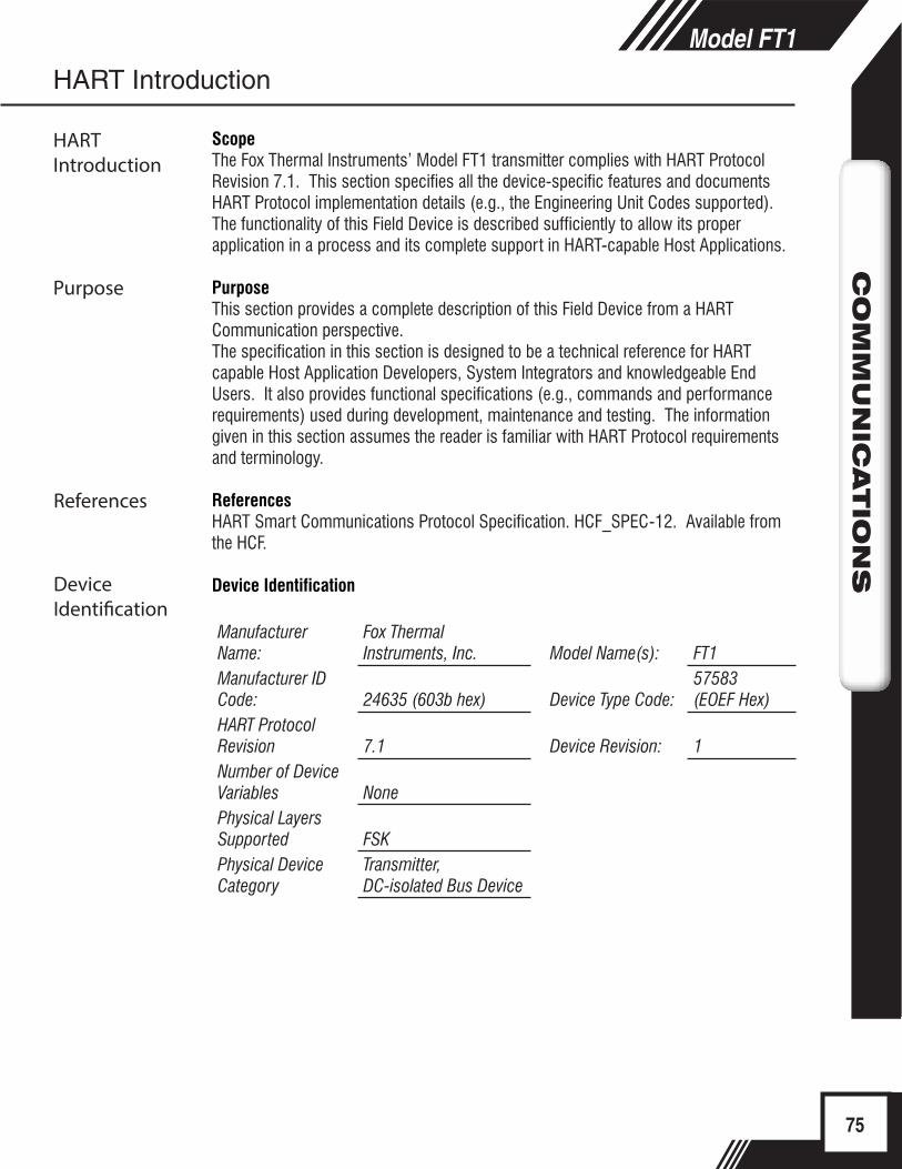
75
Model FT1C
OM
MU
NIC
ATIO
NS
Model FT1C
OM
MU
NIC
ATIO
NS
ScopeThe Fox Thermal Instruments’ Model FT1 transmitter complies with HART Protocol Revision 7.1. This section specifies all the device-specific features and documents HART Protocol implementation details (e.g., the Engineering Unit Codes supported). The functionality of this Field Device is described sufficiently to allow its proper application in a process and its complete support in HART-capable Host Applications.
PurposeThis section provides a complete description of this Field Device from a HART Communication perspective.The specification in this section is designed to be a technical reference for HART capable Host Application Developers, System Integrators and knowledgeable End Users. It also provides functional specifications (e.g., commands and performance requirements) used during development, maintenance and testing. The information given in this section assumes the reader is familiar with HART Protocol requirements and terminology.
ReferencesHART Smart Communications Protocol Specification. HCF_SPEC-12. Available from the HCF.
Device Identification
Manufacturer Name:
Fox Thermal Instruments, Inc. Model Name(s): FT1
Manufacturer ID Code: 24635 (603b hex) Device Type Code:
57583 (EOEF Hex)
HART Protocol Revision 7.1 Device Revision: 1Number of Device Variables NonePhysical Layers Supported FSKPhysical Device Category
Transmitter, DC-isolated Bus Device
HART Introduction
HART Introduction
Purpose
References
Device Identification
76
Model FT1C
OM
MU
NIC
ATIO
NS
HART Protocol Product OverviewHART communication is transmitted over the FT1 4 to 20mA flow output signal and can be monitored and configured using a HART master device or a hand-held communicator.
Process Flow Rate 4 to 20mA Analog OutputThe 4 to 20mA output of the FT1 HART represents the process flow rate measurement, linearized and scaled according to the configured range of the instrument. This output corresponds to the Primary Variable. HART Communication is supported on this loop.
The 4 to 20mA output of the FT1 should be configured for flow rate when using HART. If the 4 to 20mA output is set to report temperature, HART communication will report the 4 to 20mA value for temperature rather than flow.
HART IndicatorsLED indicator LP3 cycles on and off to indicate that the FT1 is operating. LED indicator LP2 blinks when HART signals are received and LP1 blinks when HART signals are transmitted (if nothing is connected to the 4 to 20mA output, LP2 will be on continuously).
FT1 HART Communication SetupHART communication must be selected in the FT1 Serial Communication menu for HART communication to operate. When this communication parameter is changed, power to the FT1 must be cycled for it to take effect.
NOTE: Power cycle is required for the new settings to take effect.
Device VariablesThis device does not expose any Device Variables.
Dynamic VariablesFour Dynamic Variables are implemented.
Meaning UnitsPV Flow Rate In Selected UnitsSV Total In Selected UnitsTV Temperature In Selected UnitsQV Elapsed Time In Hours
HART Protocol
HART Setup
i
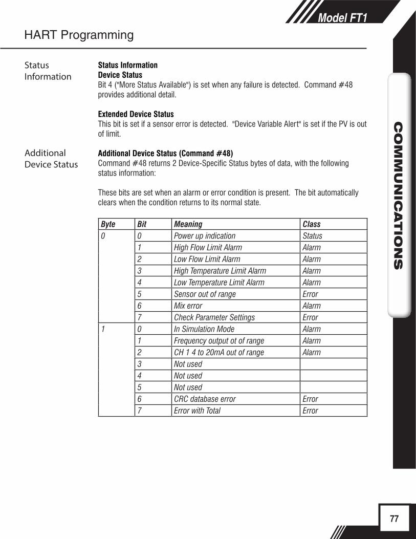
77
Model FT1C
OM
MU
NIC
ATIO
NS
Status Information
Status InformationDevice StatusBit 4 ("More Status Available") is set when any failure is detected. Command #48 provides additional detail.
Extended Device StatusThis bit is set if a sensor error is detected. "Device Variable Alert" is set if the PV is out of limit.
Additional Device Status (Command #48)Command #48 returns 2 Device-Specific Status bytes of data, with the following status information:
These bits are set when an alarm or error condition is present. The bit automatically clears when the condition returns to its normal state.
Byte Bit Meaning Class0 0 Power up indication Status
1 High Flow Limit Alarm Alarm2 Low Flow Limit Alarm Alarm3 High Temperature Limit Alarm Alarm4 Low Temperature Limit Alarm Alarm5 Sensor out of range Error6 Mix error Alarm7 Check Parameter Settings Error
1 0 In Simulation Mode Alarm1 Frequency output ot of range Alarm2 CH 1 4 to 20mA out of range Alarm3 Not used4 Not used5 Not used6 CRC database error Error7 Error with Total Error
HART Programming
Additional Device Status

78
Model FT1C
OM
MU
NIC
ATIO
NS
Common Commands
Common-Practice Commands, Supported CommandsThe following common-practice commands are implemented:
34 Write Damping Value35 Write Range Values36 Set PV Upper Range Values37 Set PV Lower Range Values38 Reset "Configuration Changed" Flag40 Enter/Exit Fixed Current Mode44 Write PV Units45 Trim Loop Minimum46 Trim Loop Maximum48 Read Additional Device Status (Command #48 returns 2 bytes of data)59 Write Number of Response Preambles
Common-Practice Commands, Unsupported CommandsBurst Mode- This device does not support Burst Mode.Catch Device Variable- This device does not support Catch Device Variable.Device-Specific Commands- No Device-Specific commands are implemented.
ModesFixed current mode is implemented, using Command 40. This mode is cleared by power loss or reset.
DampingDamping is standard, affecting only the PV and the loop current signal.
Capability ChecklistManufacturer, model Fox Thermal Instruments, FT1Device type TransmitterHART revision 7.1Device Description available NoNumber and type of sensors 1Number and type of actuators 0Number and type of host side signals 1 : 4 to 20mA analogNumber of Device Variables 0Number of Dynamic Variables 4Mappable Dynamic Variables NoNumber of common-practice commands 17Number of device-specific commands 0Bits of additional device status 8Alternative operating modes NoBurst mode NoWrite-protection Yes
HART Programming
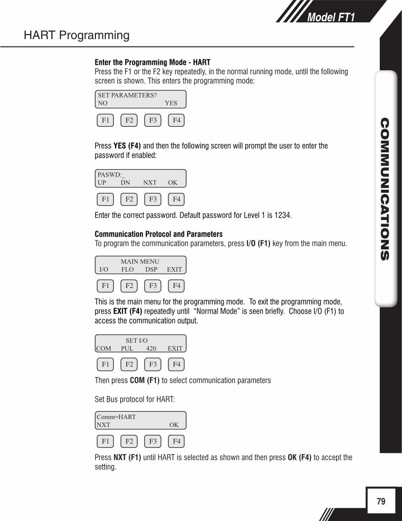
79
Model FT1C
OM
MU
NIC
ATIO
NS
Enter the Programming Mode - HARTPress the F1 or the F2 key repeatedly, in the normal running mode, until the following screen is shown. This enters the programming mode:
F1 F2 F3 F4
Press YES (F4) and then the following screen will prompt the user to enter the password if enabled:
F1 F2 F3 F4
Enter the correct password. Default password for Level 1 is 1234.
Communication Protocol and ParametersTo program the communication parameters, press I/O (F1) key from the main menu.
F1 F2 F3 F4
This is the main menu for the programming mode. To exit the programming mode, press EXIT (F4) repeatedly until “Normal Mode” is seen briefly. Choose I/O (F1) to access the communication output.
F1 F2 F3 F4
Then press COM (F1) to select communication parameters
Set Bus protocol for HART:
F1 F2 F3 F4
Press NXT (F1) until HART is selected as shown and then press OK (F4) to accept the setting.
HART Programming
PASWD:_UP DN NXT OK
MAIN MENU I/O FLO DSP EXIT
Comm=HARTNXT OK
SET PARAMETERS?NO YES
SET I/OCOM PUL 420 EXIT
80
Model FT1C
OM
MU
NIC
ATIO
NS
MAIN
TEN
AN
CE
Model FT1
PRECAUTIONSWARNING! BEFORE ATTEMPTING ANY MAINTENANCE, TAKE THE NECESSARY SAFETY PRECAUTIONS BEFORE REMOVING THE PROBE FROM THE DUCT (EXAMPLE: PURGE LINES OF TOXIC AND/OR EXPLOSIVE GAS, DEPRESSURIZE, ETC...).
WARNING! EXPLOSION HAZARD. DO NOT REMOVE OR REPLACE COMPONENTS OR FUSES UNLESS POWER HAS BEEN DISCONNECTED WHEN A FLAMMABLE OR COMBUSTIBLE ATMOSPHERE IS PRESENT.
WARNING! EXPLOSION HAZARD. DO NOT DISCONNECT EQUIPMENT WHEN A FLAMMABLE OR COMBUSTIBLE ATMOSPHERE IS PRESENT.
Access to ElectronicsAccessing electronics is not normally required for maintenance purposes. If a loose connection is suspected, unscrew the cap of the meter, unscrew the two phillips captive screws through the display and open the display assembly to access the wiring terminations.
CAUTION! BE SURE POWER TO METER IS SWITCHED OFF BEFORE ATTEMPTING TO ACCESS ELECTRONICS. If there is a problem and a loose connection is not found, please contact Fox Customer Service for technical assistance at (831) 384-4300.
Precautions
Maintenance: Precautions
Broken or Damaged ProbeIf the sensor is broken or damaged, the probe and electronics must be returned to the factory for repair. A new sensor will be installed and calibrated. Refer to "Returning Your Meter" on p. 97.
Flow Calibration and Calibration ValidationTo ensure continued high accuracy of your Model FT1 Flow Meter, Fox Thermal Instruments Inc. provides a full NIST traceable calibration. It is recommended that the meter be returned to Fox for a calibration check in our NIST traceable labs after two years of operation to maintain absolute accuracy. It is recommended that the meter's accuracy be checked annually by performing the Zero CAL-CHECK® Calibration Validation test.
Fuse ReplacementWARNING! Turn input power OFF before removing or installing a fuse. Use only recommended fuse replacements.
Verify the fuse is defective by measuring it with an Ohm Meter (Two replacement fuses are provided with each unit). Replacement fuse is Littelfuse part number 0454.750MR
To replace the fuse:The fuse F1 is located near the power terminal block and can be removed by using tweezers or needle-nose pliers.
Sensor CleaningThe sensor is insensitive to small amounts of residue, but continued use in dirty environments will necessitate periodic cleaning. To inspect the sensor, remove power from electronics and remove the unit from the pipe or duct, exposing the sensor elements. If they are visibly dirty, clean them with water or alcohol (ethanol) using an appropriate brush until they appear clean again. Even though the sensor elements are rugged, avoid touching them with any solid object and use a light touch while cleaning them.
81
Model FT1C
OM
MU
NIC
ATIO
NS
Model FT1M
AIN
TEN
AN
CE
Maintenance: General
Maintenance
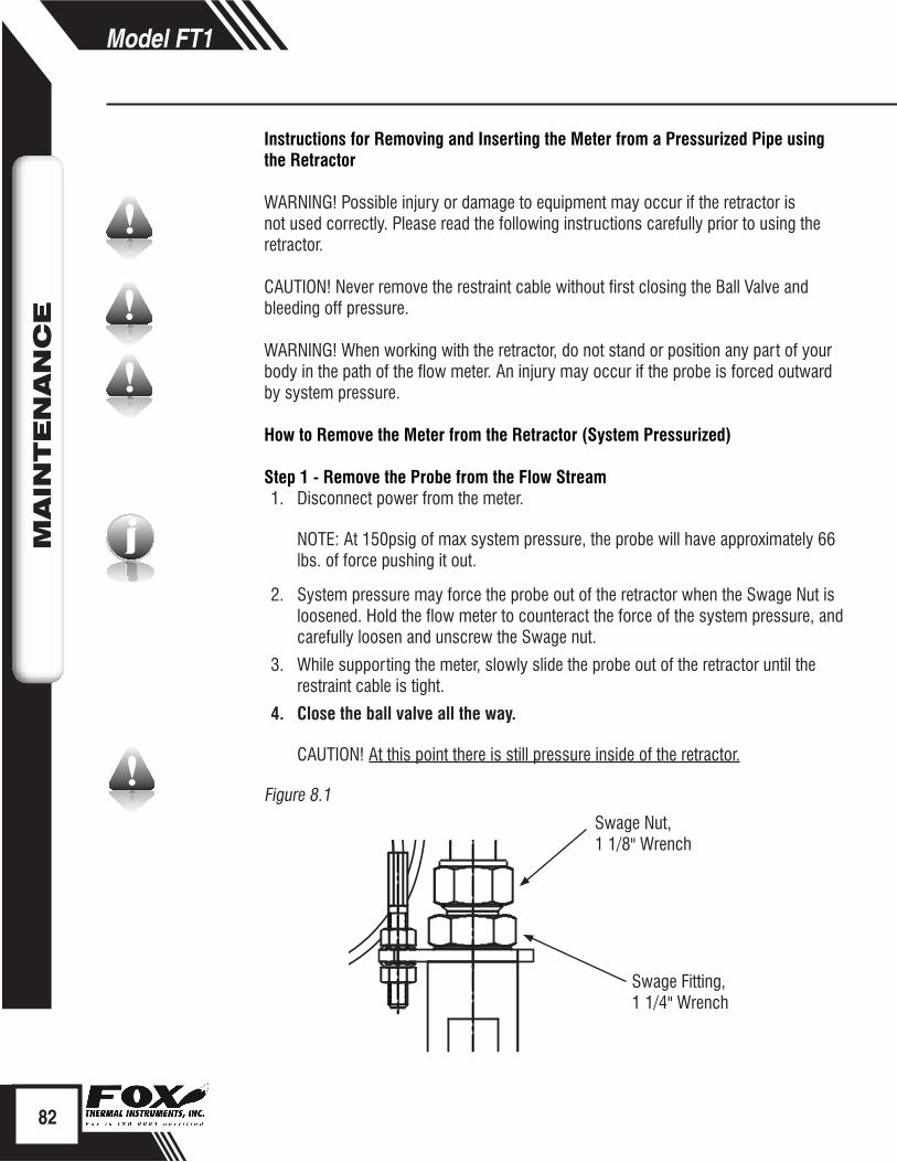
RETA
ININ
G R
ING
CEN
TER
OF
PIPE
Swage Nut, 1 1/8" Wrench
Swage Fitting, 1 1/4" Wrench
i
Instructions for Removing and Inserting the Meter from a Pressurized Pipe using the Retractor
WARNING! Possible injury or damage to equipment may occur if the retractor is not used correctly. Please read the following instructions carefully prior to using the retractor.
CAUTION! Never remove the restraint cable without first closing the Ball Valve and bleeding off pressure.
WARNING! When working with the retractor, do not stand or position any part of your body in the path of the flow meter. An injury may occur if the probe is forced outward by system pressure.
How to Remove the Meter from the Retractor (System Pressurized)
Step 1 - Remove the Probe from the Flow Stream1. Disconnect power from the meter.
NOTE: At 150psig of max system pressure, the probe will have approximately 66 lbs. of force pushing it out.
2. System pressure may force the probe out of the retractor when the Swage Nut is loosened. Hold the flow meter to counteract the force of the system pressure, and carefully loosen and unscrew the Swage nut.
3. While supporting the meter, slowly slide the probe out of the retractor until the restraint cable is tight.
4. Close the ball valve all the way.
CAUTION! At this point there is still pressure inside of the retractor.
Figure 8.1
82
Model FT1M
AIN
TEN
AN
CE
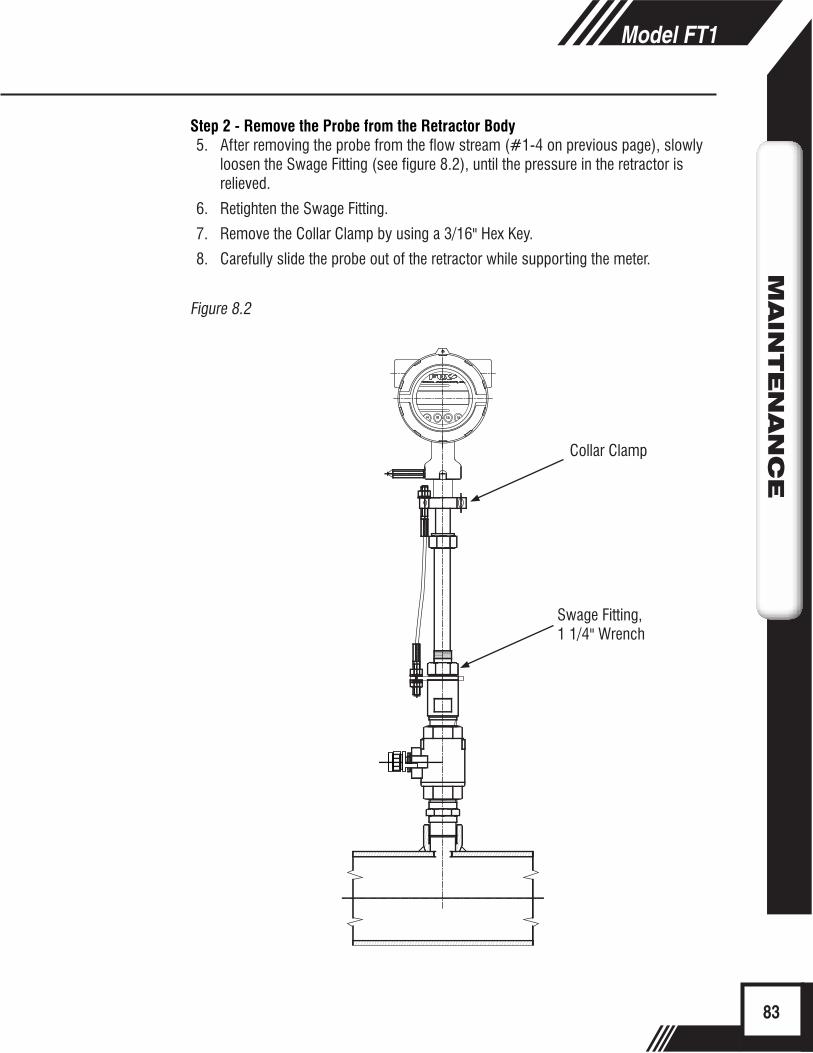
Swage Fitting, 1 1/4" Wrench
Collar Clamp
Step 2 - Remove the Probe from the Retractor Body5. After removing the probe from the flow stream (#1-4 on previous page), slowly
loosen the Swage Fitting (see figure 8.2), until the pressure in the retractor is relieved.
6. Retighten the Swage Fitting.
7. Remove the Collar Clamp by using a 3/16" Hex Key.
8. Carefully slide the probe out of the retractor while supporting the meter.
Figure 8.2
83
Model FT1M
AIN
TEN
AN
CE

Swage Nut
Swage Fitting
Collar Clamp
Collar Spacer
i
How to Insert the Probe into the Flow Stream (Valve closed, System Pressurized)1. Carefully, slide the probe into the retractor.
2. Install the collar clamp just below the collar spacer, and tighten it in place on the probe. Slide the probe back out of the retractor until the cable is straight and taut.
Figure 8.3
NOTE: At a maximum system pressure of 150psig, the force required to push the probe in place to tighten the Swage Nut will be approximately 66 lbs.
3. Slowly open the ball valve to the full open position. Push the meter and probe into the pipe, then hand tighten the Swage Nut onto the Swage Fitting.
84
Model FT1M
AIN
TEN
AN
CE
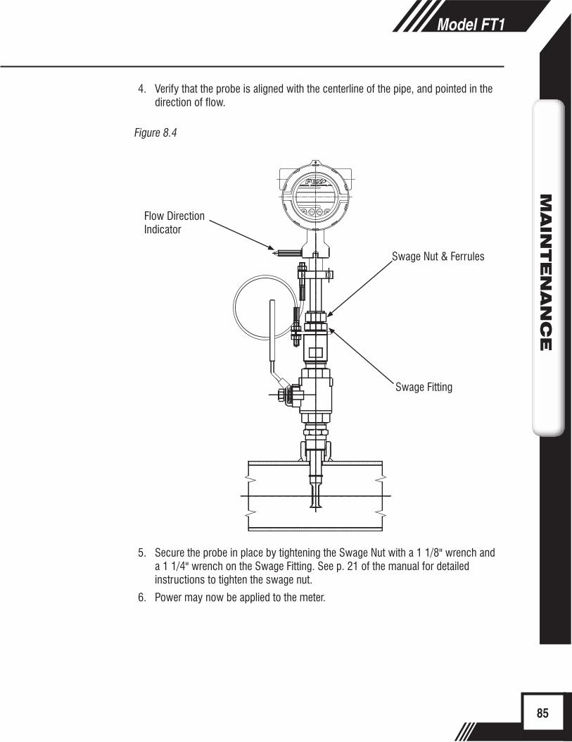
Swage Nut & Ferrules
Flow Direction Indicator
Swage Fitting
4. Verify that the probe is aligned with the centerline of the pipe, and pointed in the direction of flow.
Figure 8.4
5. Secure the probe in place by tightening the Swage Nut with a 1 1/8" wrench and a 1 1/4" wrench on the Swage Fitting. See p. 21 of the manual for detailed instructions to tighten the swage nut.
6. Power may now be applied to the meter.
85
Model FT1M
AIN
TEN
AN
CE
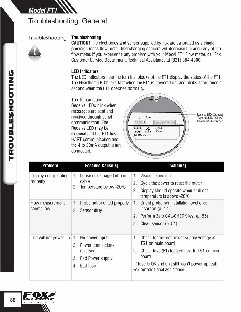
Problem Possible Cause(s) Action(s)
Display not operating properly
1. Loose or damaged ribbon cable
2. Temperature below -20°C
1. Visual inspection.
2. Cycle the power to reset the meter.
3. Display should operate when ambient temperature is above -20°C
Flow measurement seems low
1. Probe not oriented properly
2. Sensor dirty
1. Orient probe per installation sections: Insertion (p. 17),
2. Perform Zero CAL-CHECK test (p. 56)
3. Clean sensor (p. 81)
Unit will not power-up 1. No power input
2. Power connections reversed
3. Bad Power supply
4. Bad fuse
1. Check for correct power supply voltage at TS1 on main board.
2. Check fuse (F1) located next to TS1 on main board.
If fuse is OK and unit still won’t power up, call Fox for additional assistance
(-) (+) (-) (+)Power12-28VDC
4-20mA!
Transmit LED (Yellow)Heartbeat LED (Green)
Receive LED (Orange)TS1 Fuse
TroubleshootingCAUTION! The electronics and sensor supplied by Fox are calibrated as a single precision mass flow meter. Interchanging sensors will decrease the accuracy of the flow meter. If you experience any problem with your Model FT1 Flow meter, call Fox Customer Service Department, Technical Assistance at (831) 384-4300.
LED IndicatorsThe LED indicators near the terminal blocks of the FT1 display the status of the FT1. The Heartbeat LED blinks fast when the FT1 is powered up, and blinks about once a second when the FT1 operates normally.
The Transmit and Receive LEDs blink when messages are sent and received through serial communication. The Receive LED may be illuminated if the FT1 has HART communication and the 4 to 20mA output is not connected.
86
Model FT1M
AIN
TEN
AN
CE
Model FT1TR
OU
BLES
HO
OTIN
G
Troubleshooting: General
Troubleshooting
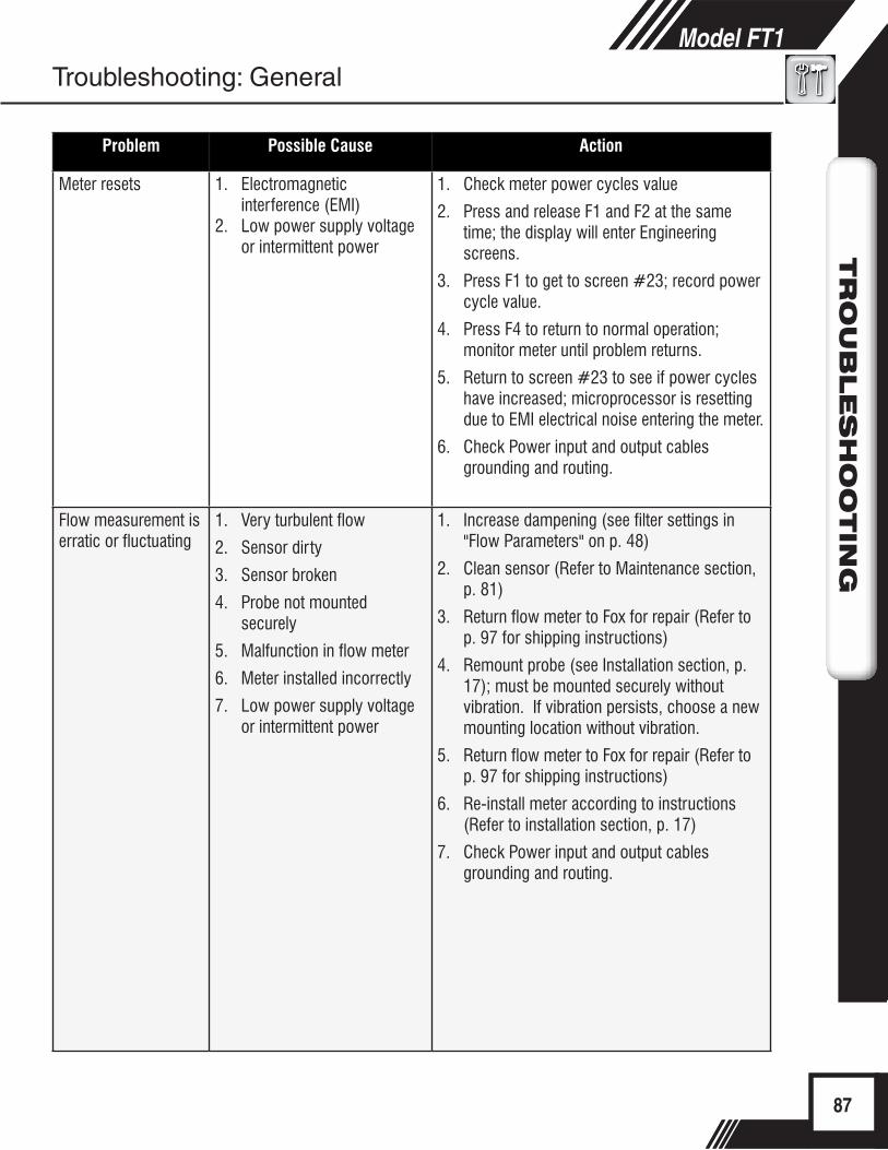
Problem Possible Cause Action
Meter resets 1. Electromagnetic interference (EMI)
2. Low power supply voltage or intermittent power
1. Check meter power cycles value
2. Press and release F1 and F2 at the same time; the display will enter Engineering screens.
3. Press F1 to get to screen #23; record power cycle value.
4. Press F4 to return to normal operation; monitor meter until problem returns.
5. Return to screen #23 to see if power cycles have increased; microprocessor is resetting due to EMI electrical noise entering the meter.
6. Check Power input and output cables grounding and routing.
Flow measurement is erratic or fluctuating
1. Very turbulent flow
2. Sensor dirty
3. Sensor broken
4. Probe not mounted securely
5. Malfunction in flow meter
6. Meter installed incorrectly
7. Low power supply voltage or intermittent power
1. Increase dampening (see filter settings in "Flow Parameters" on p. 48)
2. Clean sensor (Refer to Maintenance section, p. 81)
3. Return flow meter to Fox for repair (Refer to p. 97 for shipping instructions)
4. Remount probe (see Installation section, p. 17); must be mounted securely without vibration. If vibration persists, choose a new mounting location without vibration.
5. Return flow meter to Fox for repair (Refer to p. 97 for shipping instructions)
6. Re-install meter according to instructions (Refer to installation section, p. 17)
7. Check Power input and output cables grounding and routing.
87
Model FT1TR
OU
BLES
HO
OTIN
GModel FT1
TR
OU
BLES
HO
OTIN
G
Troubleshooting: General
88
Model FT1TR
OU
BLES
HO
OTIN
GModel FT1
TR
OU
BLES
HO
OTIN
G
Troubleshooting Zero CAL-CHECK®
If the FT1 Meter fails a Zero CAL-CHECK® Calibration Validation test, there are a few reasons that could be the cause:
1. The sensor may be dirty or damaged• Visually inspect the meter for damage. If damage is found, meter
may need to be serviced. Contact Fox Technical Assistance at 831-384-4300 for more information
• Try cleaning the sensor and try the test again• If the meter fails again, move to #2
2. The sensor may not be properly covered/isolated• Out of Pipe:
• Wind currents (fans in room included) could be affecting the sensor
• Be sure to use a clean dry plastic bottle to isolate the sensor• In Pipe:
• Make sure that there is a "no flow" or zero flow condition on the meter's sensor
• Try the test again• If the meter fails again, move to #3
3. The meter may not have stabilized properly• Make sure the meter is not being affected by vibration or other
movement• Allow the meter to stabilize without being moved or touched for 15
minutes• Try the test again• If the meter fails again, contact Fox Technical Assistance at 831-
384-4300
Troubleshooting: Zero CAL-CHECK®
Troubleshooting Zero CAL-CHECK®
Installation ProblemsThe following is a summary listing of problems that may be encountered with the installation of the FT1 Thermal Mass Flow Meter.
1. Improper wiring connections for power and/or 4 to 20mA output signal. A separate power source is recommended for the FT1 main board and the 4 to 20mA output signals. Two wires supply 24VDC power to the main board. Two wires are used for the 4 to 20mA output signals. Refer to Figure 3.3 and Figure 3.4 (p. 30, p. 31). Also refer to "Wiring Precautions" in Wiring section (p. 26) for further guidance.
2. Inadequate power source. The FT1 requires 12 to 28VDC at up to 6 Watts to operate. A 20 Watt power supply is recommended for powering the FT1 to ensure it operates properly under all conditions. If the voltage supplied at the input terminals of the FT1 is not within the range of 10VDC to 30VDC, a variety of problems can occur including a dim display, inaccurate flow readings or faulty 4 to 20mA, pulse and communication interface.
3. Flow measurement seems inaccurate.• Check to ensure that the flow meter is installed so that the Flow Direction
Indicator below the electronics housing is properly pointing in the direction of flow. Refer to Figure 2.3 (p. 19). If not, change orientation of the sensor.
• Check that the insertion depth of the sensor/probe is correct. The end of the probe should be adjusted as per Figure 2.2 (p. 18).
• Ensure that there are a minimum of fifteen diameters of straight pipe upstream of the sensor and ten diameters downstream. If complex flow disturbances are upstream of the sensor, extension of the straight pipe may be required to ensure accurate flow measurement. Contact Fox for assistance.
• Ensure that pipe inside diameter in the meter matches data on the Fox Calibration Certificate. The pipe inside diameter is programmed into the flow meter through the front panel (see Flow Parameters, p. 48).
4. Erratic flow reading (especially a flow reading spiking high). This may be a symptom of moisture in the flow stream. Fox flow meters are designed to work in relatively dry gas applications only. Contact Fox to discuss resolutions to this problem.
5. Flow meter is not responding to flow. • Check to ensure adequate power is supplied to the flow meter. If things appear
to be correct, perform this functional test before calling Fox. Carefully remove the probe and sensor from the pipe. For those flow meters with a display - and if the display is reading zero - blow on the sensor to see if a response occurs. If nothing happens, take a damp rag or sponge and place it in contact with the sensor. A reading should occur. Contact Fox Customer Service with this information.
6. Display and/or 4 to 20mA signal reading above zero flow when no flow is occurring in the pipe.If the reading is less than 5% of full scale, it is likely this is a normal condition caused by convection flow in the pipe. It does not mean that the zero of the instrument is improperly set. The Fox sensor is extremely sensitive to gas flow and can even read the small flow caused by convection. If this is an unacceptable condition, please contact Fox Customer Service for alternatives.
89
Model FT1TR
OU
BLES
HO
OTIN
G
89
Model FT1TR
OU
BLES
HO
OTIN
G
Precautions
Troubleshooting: Installation Problems
Installation Problems
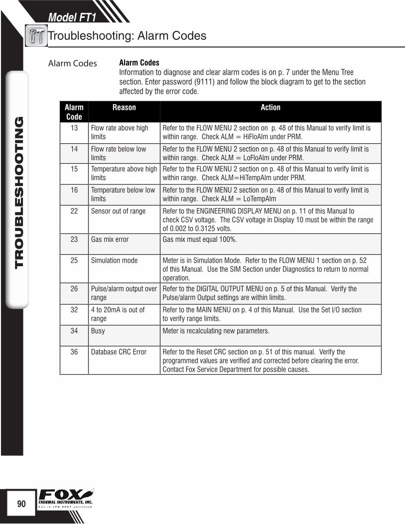
Alarm Code
Reason Action
13 Flow rate above high limits
Refer to the FLOW MENU 2 section on p. 48 of this Manual to verify limit is within range. Check ALM = HiFloAlm under PRM.
14 Flow rate below low limits
Refer to the FLOW MENU 2 section on p. 48 of this Manual to verify limit is within range. Check ALM = LoFloAlm under PRM.
15 Temperature above high limits
Refer to the FLOW MENU 2 section on p. 48 of this Manual to verify limit is within range. Check ALM=HiTempAlm under PRM.
16 Temperature below low limits
Refer to the FLOW MENU 2 section on p. 48 of this Manual to verify limit is within range. Check ALM = LoTempAlm
22 Sensor out of range Refer to the ENGINEERING DISPLAY MENU on p. 11 of this Manual to check CSV voltage. The CSV voltage in Display 10 must be within the range of 0.002 to 0.3125 volts.
23 Gas mix error Gas mix must equal 100%.
25 Simulation mode Meter is in Simulation Mode. Refer to the FLOW MENU 1 section on p. 52 of this Manual. Use the SIM Section under Diagnostics to return to normal operation.
26 Pulse/alarm output over range
Refer to the DIGITAL OUTPUT MENU on p. 5 of this Manual. Verify the Pulse/alarm Output settings are within limits.
32 4 to 20mA is out of range
Refer to the MAIN MENU on p. 4 of this Manual. Use the Set I/O section to verify range limits.
34 Busy Meter is recalculating new parameters.
36 Database CRC Error Refer to the Reset CRC section on p. 51 of this manual. Verify the programmed values are verified and corrected before clearing the error. Contact Fox Service Department for possible causes.
Alarm CodesInformation to diagnose and clear alarm codes is on p. 7 under the Menu Tree section. Enter password (9111) and follow the block diagram to get to the section affected by the error code.
90
Model FT1TR
OU
BLES
HO
OTIN
G
Troubleshooting: Alarm Codes
Alarm Codes
Appendices: Specifications
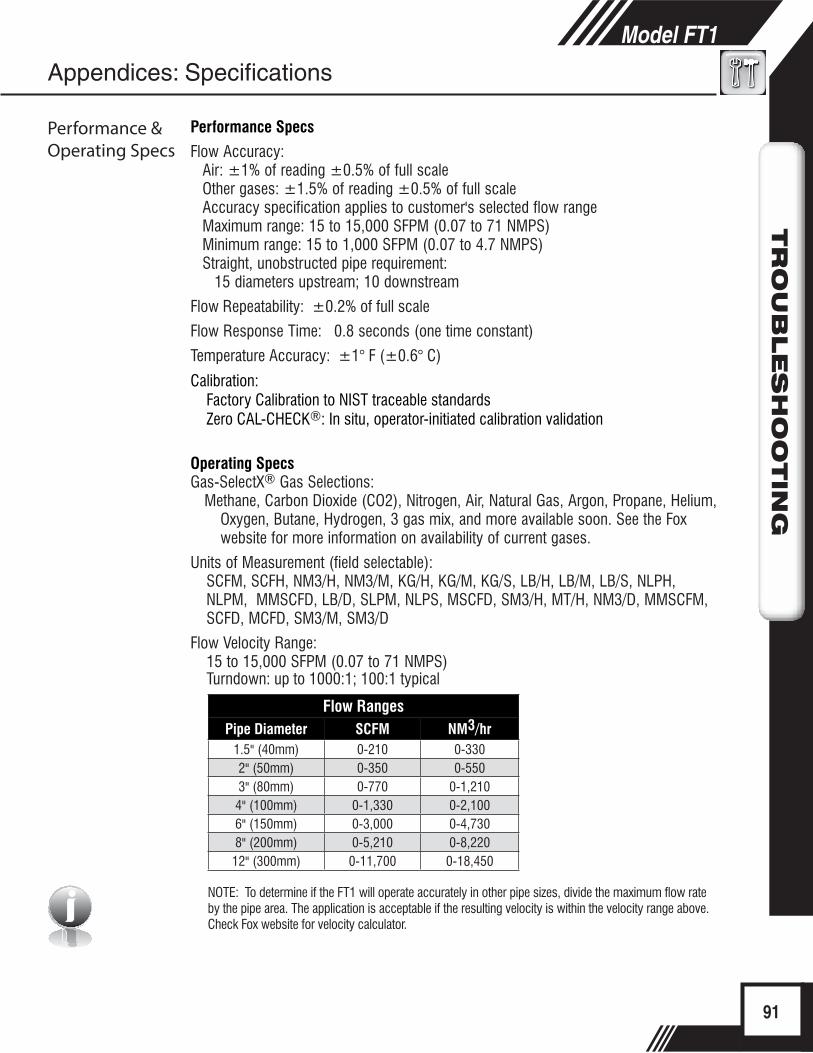
i
Performance Specs
Flow Accuracy: Air: ±1% of reading ±0.5% of full scaleOther gases: ±1.5% of reading ±0.5% of full scale Accuracy specification applies to customer's selected flow rangeMaximum range: 15 to 15,000 SFPM (0.07 to 71 NMPS)Minimum range: 15 to 1,000 SFPM (0.07 to 4.7 NMPS)Straight, unobstructed pipe requirement:
15 diameters upstream; 10 downstream
Flow Repeatability: ±0.2% of full scale
Flow Response Time: 0.8 seconds (one time constant)
Temperature Accuracy: ±1° F (±0.6° C)
Calibration:Factory Calibration to NIST traceable standardsZero CAL-CHECK®: In situ, operator-initiated calibration validation
Operating SpecsGas-SelectX® Gas Selections:
Methane, Carbon Dioxide (CO2), Nitrogen, Air, Natural Gas, Argon, Propane, Helium, Oxygen, Butane, Hydrogen, 3 gas mix, and more available soon. See the Fox website for more information on availability of current gases.
Units of Measurement (field selectable): SCFM, SCFH, NM3/H, NM3/M, KG/H, KG/M, KG/S, LB/H, LB/M, LB/S, NLPH,
NLPM, MMSCFD, LB/D, SLPM, NLPS, MSCFD, SM3/H, MT/H, NM3/D, MMSCFM, SCFD, MCFD, SM3/M, SM3/D
Flow Velocity Range: 15 to 15,000 SFPM (0.07 to 71 NMPS) Turndown: up to 1000:1; 100:1 typical
Flow RangesPipe Diameter SCFM NM3/hr
1.5" (40mm) 0-210 0-3302" (50mm) 0-350 0-5503" (80mm) 0-770 0-1,210
4" (100mm) 0-1,330 0-2,1006" (150mm) 0-3,000 0-4,7308" (200mm) 0-5,210 0-8,220
12" (300mm) 0-11,700 0-18,450
NOTE: To determine if the FT1 will operate accurately in other pipe sizes, divide the maximum flow rate by the pipe area. The application is acceptable if the resulting velocity is within the velocity range above. Check Fox website for velocity calculator.
91
Model FT1TR
OU
BLES
HO
OTIN
G
Appendices: Specifications
Performance & Operating Specs
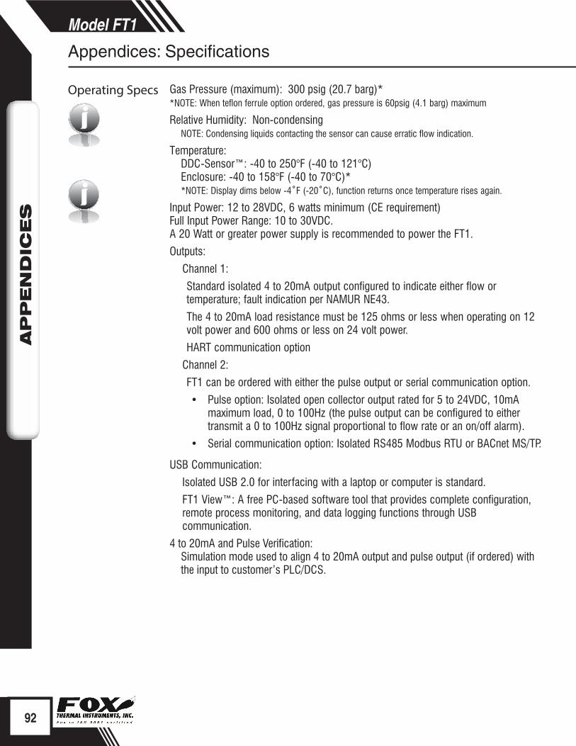
i
iGas Pressure (maximum): 300 psig (20.7 barg)* *NOTE: When teflon ferrule option ordered, gas pressure is 60psig (4.1 barg) maximum
Relative Humidity: Non-condensingNOTE: Condensing liquids contacting the sensor can cause erratic flow indication.
Temperature: DDC-Sensor™: -40 to 250°F (-40 to 121°C)
Enclosure: -40 to 158°F (-40 to 70°C)* *NOTE: Display dims below -4˚F (-20˚C), function returns once temperature rises again.
Input Power: 12 to 28VDC, 6 watts minimum (CE requirement)Full Input Power Range: 10 to 30VDC. A 20 Watt or greater power supply is recommended to power the FT1.
Outputs:
Channel 1:
Standard isolated 4 to 20mA output configured to indicate either flow or temperature; fault indication per NAMUR NE43.
The 4 to 20mA load resistance must be 125 ohms or less when operating on 12 volt power and 600 ohms or less on 24 volt power.
HART communication option
Channel 2:
FT1 can be ordered with either the pulse output or serial communication option.
• Pulse option: Isolated open collector output rated for 5 to 24VDC, 10mA maximum load, 0 to 100Hz (the pulse output can be configured to either transmit a 0 to 100Hz signal proportional to flow rate or an on/off alarm).
• Serial communication option: Isolated RS485 Modbus RTU or BACnet MS/TP.
USB Communication:
Isolated USB 2.0 for interfacing with a laptop or computer is standard.
FT1 View™: A free PC-based software tool that provides complete configuration, remote process monitoring, and data logging functions through USB communication.
4 to 20mA and Pulse Verification: Simulation mode used to align 4 to 20mA output and pulse output (if ordered) with the input to customer’s PLC/DCS.
92
Model FT1APPEN
DIC
ES
Appendices: Specifications
Operating Specs
Appendices: Specifications
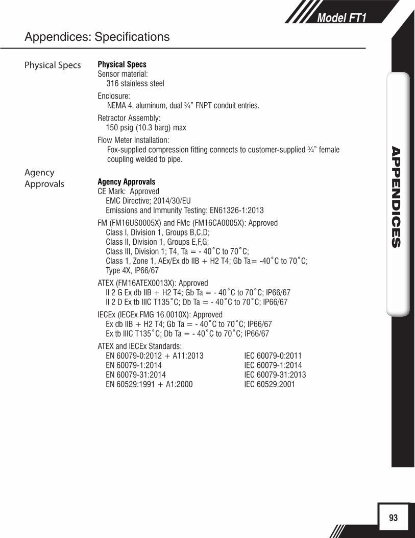
Physical SpecsSensor material:
316 stainless steel
Enclosure:NEMA 4, aluminum, dual ¾” FNPT conduit entries.
Retractor Assembly: 150 psig (10.3 barg) max
Flow Meter Installation: Fox-supplied compression fitting connects to customer-supplied ¾” female coupling welded to pipe.
Agency Approvals CE Mark: Approved
EMC Directive; 2014/30/EUEmissions and Immunity Testing: EN61326-1:2013
FM (FM16US0005X) and FMc (FM16CA0005X): ApprovedClass I, Division 1, Groups B,C,D; Class II, Division 1, Groups E,F,G; Class III, Division 1; T4, Ta = - 40˚C to 70˚C; Class 1, Zone 1, AEx/Ex db IIB + H2 T4; Gb Ta= -40˚C to 70˚C; Type 4X, IP66/67
ATEX (FM16ATEX0013X): ApprovedII 2 G Ex db IIB + H2 T4; Gb Ta = - 40˚C to 70˚C; IP66/67II 2 D Ex tb IIIC T135˚C; Db Ta = - 40˚C to 70˚C; IP66/67
IECEx (IECEx FMG 16.0010X): ApprovedEx db IIB + H2 T4; Gb Ta = - 40˚C to 70˚C; IP66/67 Ex tb IIIC T135˚C; Db Ta = - 40˚C to 70˚C; IP66/67
ATEX and IECEx Standards:EN 60079-0:2012 + A11:2013 IEC 60079-0:2011EN 60079-1:2014 IEC 60079-1:2014EN 60079-31:2014 IEC 60079-31:2013EN 60529:1991 + A1:2000 IEC 60529:2001
93
Model FT1APPEN
DIC
ES
Physical Specs
Appendices: Specifications
Agency Approvals
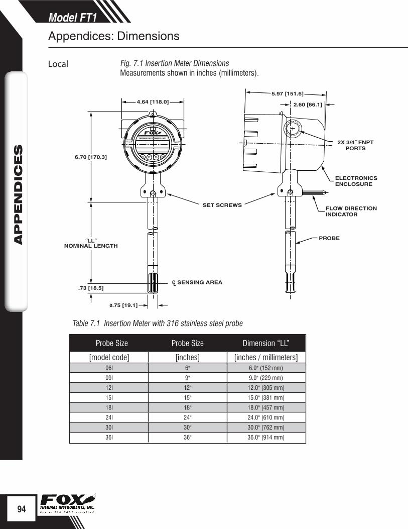
F1 F2 F3 F4
4.64 [118.0]
6.70 [170.3]
˝LL˝ NOMINAL LENGTH
CL SENSING AREA
.73 [18.5]
ø.75 [19.1]
5.97 [151.6]
2.60 [66.1]
2X 3/4˝ FNPT PORTS
ELECTRONICS ENCLOSURE
FLOW DIRECTION INDICATOR
PROBE
SET SCREWS
94
Model FT1APPEN
DIC
ES
www.foxthermalinstruments.com
Appendices: Dimensions
Local Fig. 7.1 Insertion Meter DimensionsMeasurements shown in inches (millimeters).
Table 7.1 Insertion Meter with 316 stainless steel probe
Probe Size Probe Size Dimension “LL”
[model code] [inches] [inches / millimeters]06I 6" 6.0" (152 mm)
09I 9" 9.0" (229 mm)
12I 12" 12.0" (305 mm)
15I 15" 15.0" (381 mm)
18I 18" 18.0" (457 mm)
24I 24" 24.0" (610 mm)
30I 30" 30.0" (762 mm)
36I 36" 36.0" (914 mm)
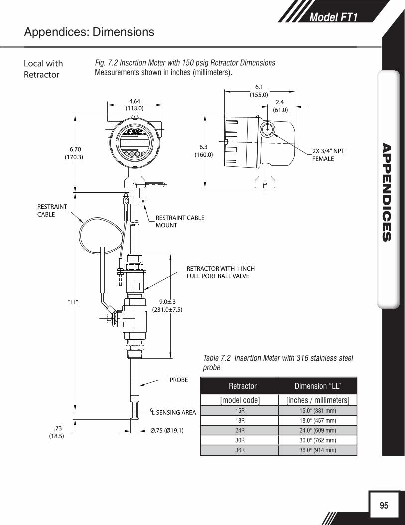
F1 F2 F3 F4
.73(18.5)
9.0±.3(231.0±7.5)
"LL"
6.70(170.3)
4.64(118.0)
6.1(155.0)
2.4(61.0)
2X 3/4" NPTFEMALE
6.3(160.0)
Ø.75 (Ø19.1)
RETRACTOR WITH 1 INCHFULL PORT BALL VALVE
RESTRAINT CABLE RESTRAINT CABLE
MOUNT
PROBE
CL SENSING AREA
95
Model FT1APPEN
DIC
ES
Local withRetractor
Fig. 7.2 Insertion Meter with 150 psig Retractor DimensionsMeasurements shown in inches (millimeters).
Table 7.2 Insertion Meter with 316 stainless steel probe
Appendices: Dimensions
Retractor Dimension “LL”
[model code] [inches / millimeters]15R 15.0" (381 mm)
18R 18.0" (457 mm)
24R 24.0" (609 mm)
30R 30.0" (762 mm)
36R 36.0" (914 mm)

96
Model FT1APPEN
DIC
ES
Warranty(a) FOX warrants that the products furnished under this Agreement will be free from defects in material and workmanship for a period of one year from the date of shipment. The customer shall provide notice of any defect to FOX, within one week after the Customer’s discovery of such defect. The sole obligation and liability of FOX, under this warranty shall be repair or replace, at its option, without cost to the Customer, the defective product or part.
(b) Upon request by FOX, the product or part claimed to be defective shall immediately be returned at the Customer’s expense to FOX. Replaced or repaired products or parts will be shipped to the Customer at the expense of FOX. FOX shall have the right of final determination as to the existence and cause of defect.
(c) There shall be no warranty or liability for any products or parts that have been subject to misuse, accident, negligence, failure of electric power or modifications by the Customer without the written approval of FOX. Final determination of warranty eligibility shall be made by FOX. If a warranty claim is considered invalid for any reason, the Customer will be charged for services performed and expenses incurred by FOX, in handling and shipping the returned unit.
(d) The liability of FOX shall be limited to replacing or repairing, at its option, any defective parts which are returned. Labor and related expenses incurred to install replacement parts are not covered by this warranty.
(e) As to replacement parts supplied or repairs made during the original warranty period, the warranty period for the replacement or repaired part shall terminate with the termination of the warranty period of the original product or part.
(f) The use of these products is under exclusive control of the purchaser and FOX specifically denies any responsibility for the calibration of units and/or accuracy of work performed or the safety of the system in which FOX products is used. EXTERNAL SAFETY DEVICES MUST BE USED WITH THIS EQUIPMENT.
(g) No warranty is made with respect to custom equipment or products produced to Buyer’s specifications except as specifically stated in writing by FOX and contained in the agreement.
(h) THE FOREGOING WARRANTY CONSTITUTES THE SOLE LIABILITY OF FOX, AND THE CUSTOMER’S SOLE REMEDY WITH RESPECT TO THE PRODUCTS AND IS IN LIEU OF ALL OTHER WARRANTIES, INCLUDING ANY WARRANTY OF MERCHANTABILITY OR FITNESS FOR A PARTICULAR PURPOSE, LIABILITIES, AND REMEDIES. EXCEPT AS THUS PROVIDED, FOX, DISCLAIMS ALL WARRANTIES, EXPRESS OR IMPLIED, INCLUDING ANY WARRANTY OF MERCHANTABILITY OR FITNESS FOR A PARTICULAR PURPOSE.
Appendices: Warranty
Warranty
Appendices: Returning Your Meter
Returning Your Meter
What to Expect During Servicing
i
Returning Your MeterThe Fox Thermal Instruments, Inc. Customer Service Department (PH: 831- 384-4300 or FAX: 831-337-5787) can help you through the process of returning a meter for service.
If it becomes necessary to return a Fox flow meter for service or recalibration, please follow these steps:
1. A Return Material Authorization (RMA) Number must be obtained from the Fox Customer Service Department prior to returning any Fox meter(s).
2. Please have your meter’s serial number(s) available.3. Read and complete the Fox RMA Customer Information Form. Be sure to initial
the decontamination statement as well as provide complete return shipping instructions (we cannot deliver to post office boxes).
4. The entire flow meter must be returned, including all electronics (unless specifically instructed to do otherwise). ALL serial numbers must match their corresponding meters. This is especially necessary when returning flow body models.
5. Clean and decontaminate all wetted parts before returning to Fox.6. Ship the meter to the following address:
Fox Thermal Instruments, Inc.399 Reservation RoadMarina, CA 93933Attn: Service Dept.[RMA Number]
NOTE: Be sure to review all of the information on the Customer Information Form before sending your meter to the Fox Customer Service Department. The Fox Shipping/Receiving Department cannot accept meters that have not been prepared appropriately.
What to expect while your meter is being servicedDepending on the type of service required when returning your Fox meter, there are varying turnover times for servicing a meter. The average time needed to service the meter is 7-10 days (not including shipping or peak production times).
If you have already shipped your meter to Fox for servicing and would like to check the status of your meter, please fill out our online Service Order Status form located at www.foxthermalinstruments.com and you will hear from a Customer Service Rep within 1 business day of your requested update.
Rush recalibration service is available for a fee. Restrictions apply.
97
Model FT1APPEN
DIC
ES
Appendices: Returning Your Meter
Returning Your Meter
What to Expect During Servicing

Aa
98
Model FT1D
EFIN
ITIO
NS
Definitions
Glossary of Terms and DefinitionsAWG American Wire GaugeBara Bar absoluteCTC ContactCAL CalibrationCHG ChangeCOM CommunicationCSV Current Sense VoltageDC Direct CurrentDN DownDSP DisplayELP Elapsed timeFeq FrequencyFt^2 Square FeetI/O Input/OutputINP InputIR Infrared (IR Buttons = optical
switches)LB PoundLB/D Pound per DayLB/H Pound per HourLB/M Pound per MinuteLB/S Pound per SecondLCD Liquid Crystal DisplayKG KilogramKG/H Kilogram per HourKG/M Kilogram per Minute KG/S Kilogram per Second M^2 Square MetermmHG Pressure in millimeters of mercuryMMSCFD Million Standard Cubic Feet per DayMXFLO Maximum FlowNEMA National Electrical Manufactures
Association
NIST National Institute of Standards and Technology
NL Normal LiterNLPH Normal Liter per HourNLPM Normal Liter per MinuteNM3 Normal cubic MeterNM3/H Normal cubic Meter per HourNM3/M Normal cubic Meter per MinuteNPT National Pipe ThreadPDA Personal hand held computerPC Personal ComputerP/U Pulse per UnitPIP A^2 Pipe AreaPLC Programmable Logic ControllerPRM ParametersPRS PressurePSIA Pounds per Square Inch AbsolutePt PointPSW PasswordSIM SimulationSCF Standard Cubic Feet SCFM Standard Cubic Feet per MinuteSCFH Standard Cubic Feet per HourSCFD Standard Cubic Feet per DaySPC Special ControlSTP Standard Temperature and
PressureTMP TemperatureTSI Internal VariableTSV Internal VariableUNT UnitU/P Unit per Pulse420 4 to 20mA output
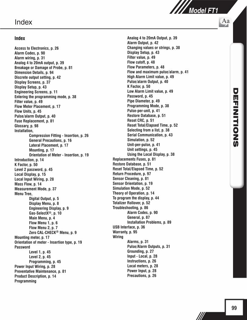
Aa
99
Model FT1D
EFIN
ITIO
NS
Index
Index
Access to Electronics, p. 26Alarm Codes, p. 90Alarm wiring, p. 31Analog 4 to 20mA output, p. 39Breakage or Damage of Probe, p. 81Dimension Details, p. 94Discrete output setting, p. 42Display Screens, p. 37Display Setup, p. 43Engineering Screens, p. 11Entering the programming mode, p. 38Filter value, p. 49Flow Meter Placement, p. 17Flow Units, p. 45Pulse/alarm Output, p. 40Fuse Replacement, p. 81Glossary, p. 98Installation, Compression Fitting - Insertion, p. 26 General Precautions, p. 16 Lateral Placement, p. 17 Mounting, p. 17 Orientation of Meter - Insertion, p. 19 Introduction, p. 14K Factor, p. 50Level 2 password, p. 45Local Display, p. 15Local Input Wiring, p. 28 Mass Flow, p. 14Measurement Mode, p. 37Menu Tree, Digital Output, p. 5 Display Menu, p. 8 Engineering Display, p. 9 Gas-SelectX®, p. 10 Main Menu, p. 4 Flow Menu 1, p. 6 Flow Menu 2, p. 7 Zero CAL-CHECK® Menu, p. 9Mounting meter, p. 17Orientation of meter - Insertion type, p. 19Password Level 1, p. 45 Level 2, p. 45 Programming, p. 45Power Input Wiring, p. 28Preventative Maintenance, p. 81Product Description, p. 14Programming
Analog 4 to 20mA Output, p. 39 Alarm Output, p. 42 Changing values or strings, p. 38 Display Setup, p. 43 Filter value, p. 49 Flow cutoff, p. 48 Flow Parameters, p. 48 Flow and maximum pulse/alarm, p. 41 High Alarm Limit value, p. 49 Pulse/alarm Output, p. 40 K Factor, p. 50 Low Alarm Limit value, p. 49 Password, p. 45 Pipe Diameter, p. 49 Programming Mode, p. 38 Pulse-per-unit, p. 41 Restore Database, p. 51 Reset CRC, p. 51 Reset Total/Elapsed Time, p. 52 Selecting from a list, p. 38 Serial Communication, p. 43 Simulation, p. 52 Unit-per-pulse, p. 41 Unit settings, p. 45 Using the Local Display, p. 38Replacements Fuses, p. 81 Restore Database, p. 51Reset Total/Elapsed Time, p. 52Return Procedure, p. 97Sensor Cleaning, p. 81Sensor Orientation, p. 19Simulation Mode, p. 52Theory of Operation, p. 14To program the display, p. 44Totalizer Rollover, p. 52Troubleshooting, p. 86 Alarm Codes, p. 90 General, p. 87 Installation Problems, p. 89USB Interface, p. 36Warranty, p. 95Wiring Alarms, p. 31 Pulse/Alarm Outputs, p. 31 Grounding, p. 27 Input - Local, p. 28 Instructions, p. 26 Local meters, p. 28 Power Input, p. 28 Precautions, p. 26
i Notes and Information
CAUTION! - is used to indicate a hazardous situation which, if not avoided, could result in minor or moderate injury.
Wiring
Troubleshooting Tips
Definition of TermsAa
Indicates compliance with the WEEE Directive. Please dispose of the product in accordance with local regulations and conventions.
Indicates compliance with the applicable European Union Directives for Safety and EMC (Electromagnetic Compatibility Directive 2014/30/EU).
WARNING! is used to indicate a hazardous situation which, if not avoided, could result in death or serious injury.