FOURTH FIVE-YEAR REVIEW REPORT FOR THE … · SOUTH VALLEY SUPERFUND SITE ALBUQUERQUE, BERNALILLO...
244
FOURTH FIVE-YEAR REVIEW REPORT FOR THE SOUTH VALLEY SUPERFUND SITE ALBUQUERQUE, BERNALILLO COUNTY, NEW MEXICO August 2010 PREPARED BY: United States Environmental Protection Agency Region 6 Dallas, Texas
Transcript of FOURTH FIVE-YEAR REVIEW REPORT FOR THE … · SOUTH VALLEY SUPERFUND SITE ALBUQUERQUE, BERNALILLO...

FOURTH FIVE-YEAR REVIEW REPORT
FOR THE
SOUTH VALLEY SUPERFUND SITE ALBUQUERQUE, BERNALILLO COUNTY, NEW MEXICO
August 2010
PREPARED BY:
United States Environmental Protection Agency Region 6
Dallas, Texas

FOURTH FIVE-YEAR REVIEW REPORT South Valley Superfund Site EPA ID No. NMD980745558
Albuquerque, Bernalillo County, New Mexico
This memorandum documents the U.S. Environmental Protection Agency’s (EPA) performance, determinations, and approval of the South Valley Superfund Site (South Valley or the Site) Fourth Five-year Review (FYR) under Section 121(c) of the Comprehensive Environmental Response, Compensation, and Liability Act, Title 42 United States Code, Section 9621(c), as provided in the attached Fourth FYR Report prepared by EA Engineering, Science, and Technology, Inc. (EA) on behalf of the EPA.
Background
The Fourth FYR for the Site was performed through a review of site documents and site-specific requirements, site inspections performed on 21 January 2010 at the Univar USA Inc. (Univar) facility and on 27 January and 5 February 2010 at the General Electric Aviation (GEA) facility, interviews with stakeholders, and a review of data collected at the Site during the Fourth FYR period. Previously, FYRs were performed separately in September 2005 for the Univar and GEA facilities.
The South Valley Site is composed of six operable units (OUs): (1) OU 01 – San Jose 6 (SJ-6) well; (2) OU 02 – SJ-6 OU vicinity area; (3) OU 03 – Edmunds Street Ground Water OU; (4) OU 04 – Edmunds Street Source Control, consisting of the vadose zone at Univar; (5) OU 05 – Former Plant 83/General Electric OU Shallow Zone, consisting of the unsaturated and saturated portion of the shallow zone aquifer at GEA; and (6) OU 06 – Former Plant 83/General Electric OU Deep Zone, consisting of the deep aquifer at GEA.
Contamination with volatile organic compounds (VOCs) was first documented in municipal well SJ-6, and subsequent investigations have identified the presence of VOCs in soil and ground water at the other OUs. The site was placed on the National Priorities List on 8 September 1983.
Of the six OUs, the remedial action (RA) is considered complete at OU 01; in addition, the Record of Decision for OU 04 required no further action. RAs have been implemented at the other four OUs and were ongoing during this FYR.
Summary of Fourth Five-Year Review Findings
The RA at OU 02 consists of ground water quality monitoring and is accomplished as part of the RA at OU 06 and, as such, it is discussed under the findings for OU 06.
The RA at OU 03 consisted of ground water extraction, treatment, and recharge. The ground water treatment system at OU 03 was operational during the first part of the review period. Due to VOC concentrations decreasing to below cleanup levels for all contaminants of concern with the exception of perchloroethene (PCE) and treatment system reaching asymptotic removal rates, the system was shut off and ground water monitoring is currently performed quarterly. The only
1

exceedance since October 2008 was for PCE in one well (GM-02) at concentrations just above the applicable or relevant and appropriate requirements (ARARs) of 5 micrograms per liter (μg/L). Univar is currently evaluating ground water data for 1,4-dioxane from a January 2010 sample event to determine if this emerging compound, previously detected in ground water at Univar at concentrations as high as 160 μg/L in October 2009, poses a threat to human health and the environment.
During this review period, the RA at OU 05 consisted of ground water extraction, treatment, and reinjection. As of June 2005, the only VOCs detected at this OU above ARARs in the saturated portion of the Shallow Zone Aquifer were: 1,1-dichloroethane (DCA) in monitoring well SW-08 (located in South Plant 83 Area) and 1,1-dichloroethene (DCE) in monitoring well SMW-10 (located in the North Plant Area). In 2007, North Plant 83 treatment operations were terminated based on the fact that: (1) ground water remediation in the former North Plant 83 Area has reached asymptotic conditions, (2) VOC removal rates were minimal, and (3) VOCs in ground water have been below ARARs for at least 2 years in all monitoring and extraction wells. Following a single detection of 1,1-DCE at 5.9 μg/L above the cleanup level, the treatment system was brought up on-line in 2008 and was again shut off in October 2009. The ground water extraction continues in the South Plant 83 Area from one extraction well; the only exceedance in fourth quarter 2009 was in SW-08 for 1,1-DCA at 37 μg/L.
The RA at OU 06 consisted of ground water extraction, treatment, and reinjection. Contamination above ARARs for 1,1-DCA, trichloroethene (TCE), and PCE was present in eight wells at the beginning of the review period and in only four wells as of November 2009. The ground water treatment system has been effective in removing contaminants from ground water and plumes have decreased in size considerably during the review period. Containment has been achieved for all impacted wells but one, in which concentrations of 1,1-DCE, PCE, and TCE are currently increasing.
2

Actions Recommended
The following actions are recommended for the South Valley Superfund Site:
• 1,4-Dioxane – continue sampling for this compound at OU 03 (Univar). In addition, an evaluation should be performed to determine if additional remedial activities are needed.
• Ethylene dibromide – for OUs 05 and 06 (GEA), the Performance and Compliance Monitoring Plan should be updated to satisfy the current Maximum Contaminant Level for this compound (0.05 μg/L); analytical methods should be selected to consistently meet the ARAR and the ground water discharge permit limit of of 0.05 μg/L.
• Methyl tertiary butyl ether (MTBE) –notify Respondents of the First Amended Unilateral Administrative Order (CERCLA-VI-14-91, Oct. 8, 1991) and the New Mexico Environment Department (NMED) Groundwater Quality Bureau of information that shows the migration of MTBE in the Deep Zone Aquifer at the GEA site from offsite sources. This information indicates that plumes of petroleum hydrocarbons, currently being remediated at the adjacent sites under the regulatory authority of NMED, may not be contained in the Deep Zone Aquifer.
• Public Outreach – increasing the frequency of public updates and dissemination of information concerning the progress of the remedy at the Site. In addition, communication of GEA’s continued commitment to complete the cleanup of the OUs for which they are responsible, should alleviate concerns that cleanup will be impacted by GEA closing the facility in Albuquerque.
• TCE and 1,1-DCE – at OU 06 (GEA), further evidence is necessary to demonstrate that TCE and 1,1-DCE are remediated within the 4,500 – 4,600 feet above mean sea level depth horizon; provide further documentation of the capture of the contamination in WB-02(4) by extraction well EW-002; and, evaluate whether additional monitoring wells are necessary to delineate the impact within this depth horizon.
Determinations
Based on the information available during the Fourth FYR, the following determinations were made for the selected remedies for the OUs at the South Valley Superfund Site:
• OU 01 – The remedy is protective of human health and the environment.
• OU 02 – The remedy is protective of human health and the environment.
• OU 03 – The remedy currently protects human health and the environment because the remedy consisting of ground water recovery and treatment functioned as designed. However, in order for the remedy to be protective in the long-term, the presence of 1,4-dioxane in ground water should be evaluated.
3

• OU 04 - The remedy is protective of human hea lth and the environment.
• OU 05 - The remedy is protective of human hea lth and the environment.
• OU 06 - The remedy currently protects human health and the env ironment because the remedy consisting of water recovery and treatment functi oned as des igned. However, in order fo r the remedy to be protecti ve in the long-term, the fo ll owing actions need to be taken: ( I) coord inate with NMED regarding the recent increase ofMTB E concentrati ons; and (2) evaluate and address the TCE and I, I-DCE concentration increases in the 4,500-4,600 ground water depth e levati on.
The remedial actions at OU 0 I, OU 02, OU 04, and OU 05 are protective. The remedial actions at OU 03 and OU 06 are protecti ve in the short-tenn . However, for OU 03 and O U 06, the recommendati ons and fo llow-up acti ons identifi ed in thi s FYR process should be addressed to ensure the long-term remedy will remain protective of human hea lth and the environment.
. /} .~i£iBY:~./ ; Sanl uel Coleman, P.E. Date Di rector Superfund Division, Region 6 U.S. Environmental Protecti on Agency
4

CONCURRENCES:
FOURTH FIVE-YEAR REVIEW REPORT SOUTH VALLEY SUPERFUND SITE
EPA ID No. NMD980745558
By: Date: '&- 3-10 lJZd?JalkAt/7 Michae l Hebert, U.S. EPA Remed ial Project Manager
By:7tJY~<{ . Date:t9rs~enn6B1~EPA Acting Chief, Loui siana/Mew Mex ico/Oklahoma Section
~~~- /'-''-=/+hL.:"'-0", _---"r-,;; 'fo __ Deputy Associate Director, Remedia l Branch
~ ~~ ~ .N.Y-"",harles Faultry , u.s. EPA
Associate Director, Remedial Branch
1 0Date: A u } .. /0 <../
At mey, Office of Re . I I Counsel
Date: _a3=-=J'.Ir-,-/2.--#-/_IO___
~
,I1/ ~ 'Jff\I ~ • ()! :Lft ~()By: [7:;11r--- \~ V-? Date: __0-"-_--'-1_1 ____
Pam Phillips, U.S. EPA Deputy Director, Superfund Divis ion
Jose 1 E. Compton Ill, U.S.
ranch , Office of Regional Coun se l
5

CONTENTS
Section Page
LIST OF FIGURES ..................................................................................................................... iv LIST OF TABLES ....................................................................................................................... iv LIST OF ACRONYMS AND ABBREVIATIONS .....................................................................v
EXECUTIVE SUMMARY .......................................................................................................... 1
1.0 INTRODUCTION............................................................................................................. 1
2.0 SITE CHRONOLOGY..................................................................................................... 4
3.0 BACKGROUND ............................................................................................................... 4
3.1 PHYSICAL CHARACTERISTICS ....................................................................... 4 3.2 LAND AND RESOURCE USE ............................................................................. 6
3.2.1 Former Use at Univar.................................................................................. 6 3.2.2 Former Use at GEA .................................................................................... 7 3.2.3 Former Use in the Vicinity of Univar and GEA......................................... 7
3.3 HISTORY OF CONTAMINATION ...................................................................... 7 3.3.1 Univar Investigations .................................................................................. 8 3.3.2 GEA Investigations..................................................................................... 9
3.4 INITIAL RESPONSE........................................................................................... 10 3.5 BASIS FOR TAKING ACTION.......................................................................... 11
3.5.1 Univar Basis for Taking Action................................................................ 11 3.5.2 GEA Basis for Taking Action................................................................... 11
4.0 REMEDIAL ACTIONS ................................................................................................. 12
4.1 SELECTED REMEDY......................................................................................... 12 4.1.1 Univar Selected Remedy........................................................................... 12 4.1.2 GEA Selected Remedies ........................................................................... 13
4.1.2.1 Soil Vapor Extraction................................................................. 14 4.1.2.2 VOCs Removal from the Shallow Zone Aquifer (OU 05)......... 14 4.1.2.3 VOCs Removal from the Deep Zone Aquifer............................ 16
4.2 REMEDY IMPLEMENTATION......................................................................... 17 4.2.1 Univar Remedy Implementation............................................................... 17 4.2.2 GEA Remedy Implementation.................................................................. 19
4.2.2.1 Shallow Zone Aquifer Remedy Implementation ....................... 19 4.2.2.2 Deep Zone Aquifer Remedy Implementation ............................ 20
4.3 OPERATION AND MAINTENANCE................................................................ 22 4.3.1 Univar Remedy Operation and Maintenance............................................ 22 4.3.2 GEA Operation and Maintenance............................................................. 25
4.3.2.1 Shallow Zone Aquifer Remediation System O&M ................... 25 4.3.2.2 Deep Zone Aquifer Remediation System O&M........................ 28
i

CONTENTS (Continued)
Section Page
4.4 OPERATION AND MAINTENANCE COST..................................................... 30
5.0 PROGRESS SINCE THE THIRD FYR....................................................................... 32
5.1 PROTECTIVENESS STATEMENT FROM THIRD FYR ................................. 32 5.2 THIRD FYR RECOMMENDATIONS AND FOLLOW-UP ACTIONS............ 32
5.2.1 Univar Recommendations and Follow-Up Actions.................................. 32 5.2.2 GEA Recommendations and Follow-Up Actions..................................... 33
5.2.2.1 OU 02 ......................................................................................... 33 5.2.2.2 OU 05 ......................................................................................... 33 5.2.2.3 OU 06 ......................................................................................... 34
5.3 STATUS OF RECOMMENDED ACTIONS....................................................... 34 5.3.1 Status of Recommended Actions for Univar OU 03 ................................ 34 5.3.2 Status of Recommended Actions for GEA OUs....................................... 35
5.3.2.1 OU 02 ......................................................................................... 35 5.3.2.2 OU 05 ......................................................................................... 35 5.3.2.3 OU 06 ......................................................................................... 36
6.0 FIVE-YEAR REVIEW PROCESS ............................................................................... 36
6.1 ADMINISTRATIVE COMPONENTS ................................................................ 36 6.2 COMMUNITY INVOLVEMENT ....................................................................... 37 6.3 DOCUMENT REVIEW ....................................................................................... 37 6.4 DATA REVIEW................................................................................................... 37
6.4.1 Data Review for Univar OU 03 ................................................................ 37 6.4.2 Data Review for GEA OU 05 ................................................................... 40 6.4.3 Data Review for GEA OUs 02 and 06, Deep Zone Remediation System 43 6.4.4 1,4-Dioxane in Deep Zone Ground Water................................................ 46
6.5 ARAR REVIEW................................................................................................... 46 6.5.1 Univar ARARs Review............................................................................. 46 6.5.2 GEA ARARs Review ............................................................................... 48
6.6 SITE INSPECTION.............................................................................................. 49 6.7 SITE INTERVIEWS............................................................................................. 50
7.0 TECHNICAL ASSESSMENT....................................................................................... 51
7.1 QUESTION A: IS THE REMEDY FUNCTIONING AS INTENDED BY THE DECISION DOCUMENTS? ................................................................................ 51
7.2 QUESTION B: ARE THE ASSUMPTIONS USED AT THE TIME OF REMEDY SELECTION STILL VALID?............................................................ 53
7.3 QUESTION C: HAS ANY OTHER INFORMATION COME TO LIGHT THAT COULD CALL INTO QUESTION THE PROTECTIVENESS OF THE REMEDY?............................................................................................................ 54
7.4 TECHNICAL ASSESSMENT SUMMARY........................................................ 54
ii

CONTENTS
Section Page
8.0 INSTITUTIONAL CONTROLS................................................................................... 55
8.1 TYPES OF INSTITUTIONAL CONTROLS IN PLACE AT THE SITE ........... 55 8.2 EFFECT OF FUTURE LAND USE PLANS ON INSTITUTIONAL CONTOLS
............................................................................................................................... 56 8.3 PLANS FOR CHANGES TO SITE CONTAMINATION STATUS .................. 57
9.0 ISSUES............................................................................................................................. 57
10.0 RECOMMENDATIONS AND FOLLOW-UP ACTIONS ......................................... 58
11.0 PROTECTIVENESS STATEMENT............................................................................ 59
12.0 NEXT REVIEW.............................................................................................................. 59
Attachments
1 Documents Reviewed 2 Site Inspection Checklists 3 Interview Records 4 Site Inspection Photographs
iii

LIST OF FIGURES Figure
1 Site Location Map
2 Univar USA, Inc. – Well Locations
3 General Electric Aviation – Shallow Zone Ground Water Well Locations
4 General Electric Aviation – Deep Zone Ground Water Well Locations
LIST OF TABLES Table
1 Chronology of Site Events
2 Univar USA, Inc. Perchloroethene Threshold Concentration Values
3 Annual Operation and Maintenance Costs
4 Concentrations of 1,4-Dioxane in Univar USA, Inc, Wells
5 Concentrations of Site-Related VOCs in Samples Collected from Recovery and Monitoring Wells at Univar Between September 2005 and October 2009
6 GEA Shallow Zone Aquifer Treatment System Information
7 GEA Deep Zone Aquifer Treatment System Information
8 Comparison of ARARs to Current Drinking Water Standards for Univar USA, Inc. Operable Unit 03
9 Comparison of ARARs to Current Drinking Water Standards for GEA Operable Units
10 Recommendations and Follow-Up Actions
iv
LIST OF ACRONYMS AND ABBREVIATION
Amsl Above mean sea level Aestus Aestus, Inc. AMAFCA Albuquerque Metropolitan Arroyo and Flood Control Authority ARAR Applicable or relevant and appropriate requirement ARCADIS ARCADIS G&M, Inc. Axis Axis Group, Inc.
bgs Below ground surface
Canonie Canonie Environmental Services, Corp. CERCLA Comprehensive Environmental Response, Compensation, and Liability Act COC Contaminant of concern
DCA Dichloroethane DCE Dichloroethene
EA EA Engineering, Science, and Technology, Inc. Edmunds Edmunds Chemical Company EPA U.S. Environmental Protection Agency Region 6 ESD Explanation of Significant Difference
ft Feet(foot) FYR Five-year review
G&M Geraghty & Miller, Inc. GEA General Electric Aviation gpm Gallon per minute GWQB Groundwater Quality Bureau
H+GCL Hydrometrics and Geosciences Consultants Limited HLA Harding Lawson Associates
μg/L Micrograms per liter MCL Maximum Contaminant Level MTBE Methyl tertiary butyl ether
NCP National Oil and Hazardous Substances Pollution Contingency Plan NMAC New Mexico Administrative Code NMED New Mexico Environment Department NMWQCC New Mexico Water Quality Control Commission NPL National Priorities List
O&M Operation and maintenance OSWER Office of Solid Waste and Emergency Response
v

LIST OF ACRONYMS AND ABBREVIATION (Continued)
OU Operable unit
PCE Perchloroethene PRP Potentially responsible party
RA Remedial action RAP Remedial Action Plan ROD Record of Decision
SARA Superfund Amendments and Reauthorization Act SEC SEC Corporation
TCA Trichloroethane TCE Trichloroethene
U.S.C. United States Code Univar Univar USA, Inc.
VES Vapor extraction system VOC Volatile organic compound
WB Westbay WES Water Equipment Services, Inc.
vi

EXECUTIVE SUMMARY
The U.S. Environmental Protection Agency Region 6 (EPA) has conducted the Fourth Five-year
Review (FYR) of the remedial actions (RAs) implemented at the South Valley Superfund Site
(Site) in Bernalillo County, New Mexico. The purpose of this Fourth FYR was to determine
whether the selected remedies for the Site continue to protect human health and the environment.
It is to be noted that this is the first FYR performed for the entire Site. Previously, FYRs were
performed separately in September 2005 for the Univar USA, Inc. (Univar) and General Electric
Aviation (GEA) facilities.
The FYR for the Site was performed through a review of historic site documents and site
specific requirements; site inspections performed on 21 January 2010 at Univar and on 27
January and 5 February 2010 at GEA; interviews with stakeholders; and a review of data
collected at the Site during the previous review periods for GEA and Univar, respectively.
The South Valley Site is composed of the six operable units (OUs):
• OU 01 – Consists of San Jose 6 (SJ-6) well; this well was contaminated with volatile organic compounds (VOCs). The remedial goal was to eliminate the threat to human health posed by introducing water from this well into City of Albuquerque drinking water supply. The remedial goal was achieved by plugging and replacing well SJ-6.
• OU 02 – SJ-6 OU vicinity area, for which GEA is the Potentially Responsible Party (PRP), had a remedial goal of eliminating conduit(s) for contaminant migration from the shallow to intermediate aquifers. The RA was completed by plugging shallow wells, implementing ground water monitoring, and restricting ground water use.
• OU 03 – Edmunds Street Ground Water OU, for which Univar (formerly Van Waters & Rogers) is the PRP, had a remedial goal of reducing the concentrations in ground water of site-related VOCs to acceptable levels (aquifer restoration) via a pump-treat-injection strategy.
• OU 04 – Edmunds Street Source Control consists of the vadose zone at the Univar facility. The Record of Decision (ROD) specified No Further Action.
ES-1

• OU 05 – Former Plant 83/General Electric OU Shallow Zone consists of the unsaturated and saturated portion of the shallow zone aquifer at the GEA facility. GEA (the PRP) has a goal for this OU of remediating shallow zone ground water and eliminating source materials via enhanced dewatering, soil flushing, and soil vapor extraction.
• OU 06 – Former Plant 83/General Electric OU Deep Zone, consists of the deep aquifer at the GEA facility. GEA (the PRP) has a remedial goal of hydraulically containing the plume to protect the City of Albuquerque’s water supply wells and reducing the concentrations of site-related VOCs in ground water to acceptable levels (aquifer restoration).
Of the six OUs, the RA is considered complete at OU 01; in addition, the ROD for OU 04
required no further action. RAs have been implemented at the other four OUs. The former FYR
evaluated the effectiveness of the RAs and demonstrated that the remedies in place at this Site
were protective of human health and the environment. A summary of progress toward achieving
remedial goals for OU 02, OU 03, OU 05, and OU 06 follows:
• OU 02 – RA is substantially complete and long-term ground water monitoring continues. Institutional controls are in place and maintained.
• OU 03 – During the FYR period, the treatment system at this OU operated between May 2005 and September 2006. RA has reduced plume to at or near standards and postremediation ground water monitoring is ongoing. Emergence of 1,4-dioxane as contaminant of concern (COC) may need to be addressed pending results of new sampling.
• OU 05 – During the FYR period, the ground water treatment system at this OU operated between July 2005 and December 2009. RA has virtually eliminated shallow zone impacts with the exception of isolated “hot spots” where in situ chemical oxidation is being considered to complete RAs at this OU.
• OU 06 – During the FYR period, the treatment system at this OU operated between July 2005 and December 2009. RA has hydraulically contained the plume and shrunk it to a fraction of its former volume and mass. A pumping and injection regimen is being manipulated (including additional remediation wells) to address residual contaminants in the remaining plume.
Issues noted during this FYR include the emergence of 1,4-dioxane as a potential COC at Univar, minor detection limit issues with respect to ethylene dibromide with respect to its New Mexico Water Quality Control Commission (NMWQCC) regulations discharge permit requirement at GEA, and feedback from questionnaires that public outreach with respect to sample results and remedial progress is infrequent.
ES-2

Based on the information available during the Fourth FYR, the following determinations were made for the selected remedies for the OUs at the South Valley Superfund Site:
• OU 01 – The remedy is protective of human health and the environment.
• OU 02 – The remedy is protective of human health and the environment.
• OU 03 – The remedy currently protects human health and the environment because the remedy consisting of ground water recovery and treatment functioned as designed. However, in order for the remedy to be protective in the long-term, the presence of 1,4-dioxane in ground water should be evaluated.
• OU 04 – The remedy is protective of human health and the environment.
• OU 05 - The remedy is protective of human health and the environment.
• OU 06 - The remedy currently protects human health and the environment because the remedy consisting of water recovery and treatment functioned as designed. However, in order for the remedy to be protective in the long-term, the following actions need to be taken: (1) notify Respondents of the First Amended Unilateral Administrative Order (CERCLA-VI-14-91, Oct. 8, 1991) and the New Mexico Environment Department (NMED) Groundwater Quality Bureau regarding the recent increase of methyl tertiary butyl ether concentrations; and (2) evaluate and address the trichloroethylene and 1,1-DCE concentration increases in the 4,500-4,600 ground water depth elevation.
The remedial actions at OU 01, OU 02, OU 04, and OU 05 are protective. The remedial actions
at OU 03 and OU 06 are protective in the short-term. However, for OU 03 and OU 06, the
recommendations and follow-up actions identified in this FYR process should be addressed to
ensure the long-term remedy will remain protective of human health and the environment.
ES-3
Five-Year Review Summary Form SITE IDENTIFICATION
Site Name (from Waste LAN): South Valley Superfund Site EPA ID (from Waste LAN): NMD980745558 Region: 6 State: New
Mexico City/County: Albuquerque, Bernalillo County
SITE STATUS NPL Status: Final Deleted Other (specify) Remediation Status (choose all that apply): Under Construction Operating
Complete Multiple OUs?* YES
NO
Construction Completion Date: January 1991 – OU 03 (system startup); June 1992 – OU 05 soil; May 1995 – OU 05 ground water; and April 1996 – OU 06
Has site been put into reuse? YES NO REVIEW STATUS
Reviewing Agency: EPA State Tribe Other Federal Agency Author Name: Mr. Michael Hebert Author Title: Remedial Project Manager Author Affiliation: EPA Region 6 Review Period:** Starting July 2005 for GEA OUs and May 2005 for Univar OU to 31 December 2010 Date(s) of Site Inspection: 22 January 2010 for Univar and 27 January and 5 February 2010 for GEA Type of Review: Statutory
Policy Post-SARA Pre-SARA NPL-Removal only
Non-NPL Remedial Action Site NPL State/Tribe-lead Regional Discretion
Review Number: 1 (first) 2 (second) 3 (third) Other (specify) 4 (fourth) Triggering Action:
Actual RA Onsite Construction at OU Actual RA Start Construction Completion Previous Five-Year Review Report Other (specify)
Triggering Action Date (from Waste LAN): 28 September 2005 Due Date (Five Years After Triggering Action Date): 28 September 2010
* “OU” refers to operable unit. ** The review period refers to the period during which the FYR was conducted.
ES-4
Five-Year Review Summary Form (Continued)
Issues noted during this FYR include the following:
• Standard for ethylene dibromide in the OUs 05 and 06 Performance and Compliance Monitoring Plan is higher than the current Maximum Contaminant Level (MCL) and NM WQCC standards; analytical methods did not consistently meet the ARAR and the ground water discharge permit limit of of 0.05 μg/L. .
• Concentrations for methyl tertiary butyl ether (MTBE) had an increase in two OU 06 wells, possibly indicating that the plumes of petroleum hydrocarbons remediated at the adjacent sites may not be contained.
• Feedback from questionnaire indicated that public outreach with respect to sample results and remedial progress is infrequent and there that are concerns over GEA closing the Albuquerque facility.
• Trichloroethene (TCE) and 1,1-dichloroethene (DCE) concentrations are on an upward trend in one well at OU 06; it is unclear whether extraction well EW-002 is capturing the contamination in this well; moreover, the number of monitoring wells screened between 4,500 and 4,600 feet above mean sea level limit adequate characterization.
The following actions are recommended for the South Valley Superfund Site:
• 1,4-Dioxane – continue sampling for this compound at OU 03 (Univar). In addition, an evaluation should be performed to determine if additional remedial activities are needed.
• Ethylene dibromide – for OUs 05 and 06 (GEA), the Performance and Compliance Monitoring Plan should be updated to satisfy the current MCL for this compound (0.05 μg/L); analytical methods should be selected to consistently meet the applicable or relevant and appropriate requirement (ARAR) and the ground water discharge permit limit of 0.05 μg/L.
• MTBE – notify Respondents of the First Amended Unilateral Administrative Order (CERCLA-VI-14-91, Oct. 8, 1991) and the New Mexico Environment Department (NMED) Groundwater Quality Bureau of information that shows the migration of MTBE in the Deep Zone Aquifer at the GEA site from offsite sources. This information indicates that plumes of petroleum hydrocarbons, currently being remediated at the adjacent sites under the regulatory authority of NMED, may not be contained in the Deep Zone Aquifer.
ES-5

Five-Year Review Summary Form (Continued)
• Public Outreach – increasing the frequency of public updates and dissemination of information concerning the progress of the remedy at the Site. In addition, communication of GEA’s continued commitment to complete the cleanup of the OUs for which they are responsible, should alleviate concerns that cleanup will be impacted by GEA closing the facility in Albuquerque.
• TCE and 1,1-DCE – at OU 06 (GEA), further evidence is necessary to demonstrate that TCE and 1,1-DCE are remediated within the 4,500 – 4,600 ground water depth elevation; provide further documentation of the capture of the contamination in WB-02(4) by extraction well EW-002; and, evaluate whether additional monitoring wells are necessary to delineate the impact within this groundwater depth elevation.
Protectiveness Statement and Long Term Protectiveness:
Based on the information available during the Fourth FYR, the following determinations were made for the selected remedies for the OUs at the South Valley Superfund Site:
• OU 01 – The remedy is protective of human health and the environment.
• OU 02 – The remedy is protective of human health and the environment.
• OU 03 – The remedy currently protects human health and the environment because the remedy consisting of ground water recovery and treatment functioned as designed. However, in order for the remedy to be protective in the long-term, the presence of 1,4-dioxane in ground water should be evaluated.
• OU 04 – The remedy is protective of human health and the environment.
• OU 05 - The remedy is protective of human health and the environment.
• OU 06 - The remedy currently protects human health and the environment because the remedy consisting of water recovery and treatment functioned as designed. However, in order for the remedy to be protective in the long-term, the following actions need to be taken: (1) coordinate with NMED regarding the recent increase of MTBE concentrations; and (2) evaluate and address the TCE and 1,1-DCE concentration increases in the 4,5004,600 ground water depth elevation.
The remedial actions at OU 01, OU 02, OU 04, and OU 05 are protective. The remedial actions at OU 03 and OU 06 are protective in the short-term. However, for OU 03 and OU 06, the recommendations and follow-up actions identified in this FYR process should be addressed to ensure the long-term remedy will remain protective of human health and the environment.
ES-6

1.0 INTRODUCTION
The U.S. Environmental Protection Agency Region 6 (EPA) has conducted a Fourth Five-Year
Review (FYR) of the remedial actions (RAs) implemented at the South Valley Superfund Site
(Site), located in Albuquerque, Bernalillo County, New Mexico. There are two potentially
responsible parties (PRPs) for this Site: General Electric Aviation (GEA) and Univar USA Inc.
(Univar). The review period covers the timeframe between the completion of the previous
second FYR for GEA operable units (OUs) and the previous third FYR for the Univar OUs. The
FYR report for GEA OUs (OU 02, 05, and 06) was submitted on 15 September 2005 (Water
Equipment Services, Inc. [WES] 2005), and covered the period from June 2000 through June
2005. The FYR Report for Univar OUs (OU 03 and 04) was submitted by ARCADIS G&M,
Inc. (ARCADIS) in September 2005 (ARCADIS 2005a), and covered the timeframe from
January 2000 through April 2005.
In November 2009, EPA notified Univar and GEA that they have initiated the FYR process for
the South Valley Superfund Site (EPA 2009 b,d). By providing EPA with data collected during
the last five years, EPA will deem Univar in compliance with Section VII(24) of the Consent
Decree (EPA 1990a) and GEA in compliance with Section V(J) of the Administrative Order
(EPA 1989b) that required Univar and GEA to prepare FYR reports.
The purpose of a FYR is to determine whether the remedy or remedies at a site remain protective
of human health and the environment, and to document the methods, findings, and conclusions
of the FYR in a FYR Report. FYR Reports identify issues found during the review, if any, and
make recommendations to address the issues. This Fourth FYR Report for all the OUs at the Site
documents the results of the review, which was conducted in accordance with EPA guidance on
FYRs (EPA 2001).
The FYR process is required by federal statute. The EPA must implement FYRs consistent with
the Comprehensive Environmental Response, Compensation, and Liability Act (CERCLA), 42
United States Code (U.S.C.) § 9601 et seq. and the National Oil and Hazardous Substances
1

Pollution Contingency Plan (NCP), 40 C.F.R. Part 300 et seq. CERCLA Section 121(c), as
amended, states the following:
“If the President selects an RA that results in any hazardous substances, pollutants, or contaminants remaining at the Site, the President shall review such RA no less often than each 5 years after the initiation of such RA to assure that human health and the environment are being protected by the RA being implemented.”
NCP Section 300.430(f) (4) (ii) states the following:
“If an RA is selected that results in hazardous substances, pollutants, or contaminants remaining at the Site above levels that allow for unlimited use and unrestricted exposure, the lead agency shall review such action no less often than every 5 years after the initiation of the selected RA.”
The EPA FYR guidance further states that a FYR should be conducted as a matter of policy for
the following types of actions:
• A pre-Superfund Amendments and Reauthorization Act (SARA) RA that leaves hazardous substances, pollutants, or contaminants onsite above levels that allow for unlimited use and unrestricted exposure;
• A pre- or post-SARA RA that, once completed, will not leave hazardous substances, pollutants, or contaminants onsite above levels that allow for unlimited use and unrestricted exposure but will require more than 5 years to complete; and
• A removal-only site on the National Priorities List (NPL) where the removal action leaves hazardous substances, pollutants, or contaminants onsite above levels that allow for unlimited use and unrestricted exposure and no RA has or will be conducted.
Because hazardous substances, pollutants, or contaminants at the Site remain above levels that
allow for unlimited use and unrestricted exposure, a FYR is required.
2

EPA prepared an approval memorandum for the South Valley Superfund Site which is dated
26 September 2005, approved on 28 September 2005, and includes as appendices the individual
FYR reports prepared for GEA and Univar. This approval memorandum constituted the
triggering action for preparation of this combined Fourth FYR comprising all the OUs at the Site.
This is the Fourth FYR for the Site, which for OUs 02, 05, and 06 has a review period from July
2006 through 31 December 2009, and for OU 03 from July 2005 through 31 December 2009.
The triggering action was the approval date of the FYR memorandum for the Site, 28 September
2005. The Fourth FYR methods, findings, conclusions, and recommendations are documented in
this report.
The South Valley Site is composed of the six operable units (OUs):
• OU 01 – Consists of San Jose 6 (SJ-6) well; this well was contaminated with volatile organic compounds; the Record of Decision (ROD) for this unit was signed on 22 March 1985 (EPA 1985), and was the first ROD issued for the site;
• OU 02 – SJ-6 OU vicinity area, for which GEA is the PRP; the ROD for this unit was signed on 30 September 1988 (EPA 1988d);
• OU 03 – Edmunds Street Ground Water OU, for which Univar (formerly Van Waters & Rogers) is the PRP; the ROD for this unit was signed on 28 June 1988 (EPA 1988b);
• OU 04 – Edmunds Street Source Control; this OU consists of the vadose zone at Univar, which is also the PRP; the ROD (EPA 1989a) recommended no further action;
• OU 05 – Former Plant 83/General Electric OU Shallow Zone, consisting of the unsaturated and saturated portion of the shallow zone aquifer at GEA, for which GEA is the PRP; the ROD for this unit was signed on 30 September 1988 (EPA 1988e); and
• OU 06 – Former Plant 83/General Electric OU Deep Zone, consisting of the deep aquifer at GEA, for which GEA is the PRP; the ROD for this unit was signed on 30 September 1988 (EPA 1988e).
This report documents the FYR for the Site by providing the following information: site
chronology (Section 2.0), background information (Section 3.0), an overview of the RAs
(Section 4.0), progress since the previous FYRs for the different OUs (Section 5.0), the FYR
3

process (Section 6.0), technical assessment of the Site (Section 7.0), institutional controls
(Section 8.0), issues (Section 9.0), recommendations and follow-up activities (Section 10.0),
protectiveness statement (Section 11.0), and discussion of the next review (Section 12.0).
Figure 1 provides the site location map. The report text is followed by figures and tables.
Attachment 1 provides a list of documents reviewed. Attachment 2 provides the site inspection
checklists. Attachment 3 provides the interview records. Attachment 4 provides the site
inspection photographs.
2.0 SITE CHRONOLOGY
A chronology of events for the Site is provided in Table 1. The table segregates the events
related to the site in general from the events pertinent to activities performed by the two PRPs at
the site, Univar and GEA.
3.0 BACKGROUND
This section discusses the Site’s physical characteristics, land and resource use near the Site,
history of site contamination, initial response actions, and basis for the response.
3.1 PHYSICAL CHARACTERISTICS
The South Valley Site is located at in an industrial area in the southern portion of Albuquerque,
New Mexico (Figure 1), approximately one-half mile west of the Albuquerque International
Airport and approximately one-half mile east of the Rio Grande, close to the intersection of
South Broadway and Woodward Road.
The hydrogeologic units encountered at the Site are described in the paragraphs below (WES
2005). Ground water is located in the Santa Fe Group Aquifer. The remediation at Univar,
OU 03, is limited to the shallow portion of the Aquifer while at GEA, because the impact
extends deeper within the formation, the remediation addresses different depth horizons that
were divided by convention into the Shallow Zone Aquifer and the Deep Zone Aquifer. The
4

Deep Zone Aquifer includes both the Intermediate Zone and Deep Zone referred to in the ROD
(EPA, 1988). OU 05 addresses impacts to the Shallow Zone Aquifer located proximate to the
South Plant 83 and North Plant 83 Areas and a portion of the San Jose residential neighborhood,
located just north of North Plant 83 Area. OU 06 addresses impacts to portions of the Deep
Zone Aquifer found east of the Plant 83 facilities, south of Woodward Road and east of South
Broadway. Descriptions of the Shallow Zone and Deep Zone Aquifers are provided below as
outlined in the Second FYR for GEA (WES 2005).
Shallow Zone Aquifer
By convention, the Shallow Zone Aquifer ground water refers to ground water that is above the
relatively continuous silty clay layer and/or above an elevation of 4,900 feet (ft) above mean sea
level (amsl). In the North Plant 83 Area, there is a continuous silty clay layer underneath the
aquifer. Accordingly, the Shallow Zone Aquifer ground water is primarily perched. Perched
ground water does not to have a uniform flow direction, but rather flows in directions dictated by
undulating surface of the underlying silty clay layer. In the South Plant 83 Area, the silty clay
layer underneath the aquifer is not continuous. Hence, the ground water generally flows west to
east. The Shallow Zone formation consists of layers of coarse-grained sands, silty sands, clays,
and silty clays. This Shallow Zone Aquifer generally extends to a depth of approximately 20-25
ft below ground surface (bgs). The Shallow Zone formation is underlain by a relatively
continuous silty clay layer, except at the south end of South Plant 83 where it is absent or does
not provide hydraulic separation from the Deep Zone Aquifer.
Deep Zone Aquifer
By convention, the Deep Zone Aquifer refers to the aquifer below an elevation of 4,900 ft amsl.
The following text summarily describes the Deep Zone Aquifer geology as characterized and
reported previously. The geology consists of unconsolidated alluvial units of the older Santa Fe
Group. These sediments (down to approximately 4,300 ft amsl) are primarily ancestral Rio
Grande-related, braided fluvial deposits. These sediments contain lenticular deposits of finer
grained, relatively lower conductivity sands, silts, and clays. Sediments within the upper 600
700 ft of the Deep Zone Aquifer (the area where ground water is being remediated) are
characterized by high proportions of sands and gravels that form extensive and locally high
5
conductivity units across the site. Discontinuous silts and clays are present within this interval,
and the cumulative effect of many of these lower conductivity layers is to limit the downward
rate of contaminant movement in the vertical direction. Note that these silts and clays form
confining layers in upper portions of the aquifer, but these confining layers are not laterally
extensive. There is no evidence to suggest a laterally extensive confining layer east of the
Albuquerque Metropolitan Arroyo and Flood Control Authority (AMAFCA) South Diversion
Channel, in the area of interest.
3.2 LAND AND RESOURCE USE
Historical and current land use surrounding the Site is primarily industrial, with some residential
use to the north of the site.
3.2.1 Former Use at Univar
The Univar Site has been used for various industrial and commercial purposes for approximately
50 years. In 1965, Edmunds Chemical Company (Edmunds) purchased the land. Edmunds and
its successor, SEC Corporation (SEC), distributed various industrial chemicals in addition to
selling dry ice, chlorine, and ammonia gas. In 1971, SEC sold the industrial chemical portion of
its business to Univar (formerly Van Waters & Rogers) and SEC continued in the business of
selling dry ice, chlorine, and ammonia gas. Univar began leasing the eastern portion of the
property for its activities, while SEC continued to occupy the rest of the site. In 1974, Univar
enhanced a naturally occurring shallow depression (now called the SV-10 area) to control
stormwater runoff on the eastern portion of the site.
In 1977, AmeriGas acquired SEC and continued the dry ice, chlorine, and ammonia gas
operation, while Univar remained as a tenant. AmeriGas sold the property in 1982 to Dixie
Chemical, and re-acquired the property later that same year. Since 1985, only Univar has been
active at the site. In June 1988, Univar purchased the property from AmeriGas and has since
owned and operated the site.
6

3.2.2 Former Use at GEA
The Plant 83 facility consisted of two facilities: North Plant 83 Area located north of Woodward
Road, which was demolished in October 1997, and South Plant 83 Area located south of
Woodward Road, which is still in use today. Both facilities have been used for manufacturing
purposes since the 1950s, first by Eidel Manufacturing, followed by the Atomic Energy
Commission through its contractor American Car Foundry, followed by U.S. Air Force through
its contractor General Electric, and finally by GEA as facility owner since 1984. Note that for
simplicity, the current name of the owner, GEA, will be used throughout this report.
3.2.3 Former Use in the Vicinity of Univar and GEA
Several industrial and commercial operations were located in the proximity of the Univar and
GEA sites: the Whitfield Tank Lines, Texaco Terminal, Chevron Terminal, ATA Pipeline, and
Duke City Petroleum. RAs to mitigate hydrocarbons contamination at these other locations are
handled under separate agreements with New Mexico Environment Department (NMED)
Groundwater Quality Bureau (GWQB).
3.3 HISTORY OF CONTAMINATION
In 1978, the City of Albuquerque analyzed samples from the San Jose and Miles municipal well
fields. Low levels of volatile organic compounds (VOCs) were detected in wells SJ-3 (about
one-half mile northwest of North Plant 83 Area) and SJ-6 (just southeast of the intersection of
Woodward Road and Broadway Road), which were located in the San Jose well field and in well
Miles-1, located in the Miles Well Field. These wells were temporarily taken out of service.
Well Miles-1 was returned to service as repeated chemical analysis failed to confirm the
presence of any contaminants. Both SJ-3 and SJ-6 wells were plugged and abandoned in 1994 as
part of the RA under the ROD for OU 01 (also known as the SJ-6 ROD). The remedial action at
OU 01 was then completed through the installation of a well that replaced the amount of water
taken out of service through the well abandonment.
7

In 1981, the EPA and NMED (formerly the Environmental Improvement Division of the New
Mexico Health and Environment Department) designated a 1-square mile area around SJ-6 as a
Superfund site (SJ-6 Study Area) which was added to the NPL. This area became OU 02. In
order to locate potential sources of ground water contamination in the vicinity of SJ-6, the
NMED conducted a regional study, entitled “Organic Ground-Water Pollutants in the South
Valley of Albuquerque, New Mexico,” December 1982. As a result of the investigation, EPA
and NMED identified the following six potential source locations in the South Valley: General
Electric/Air Force (now GEA), Chevron, Texaco, Duke City Distributing, Whitfield Tank Lines,
and the Edmunds Street property (now Univar). The owners of these sites were identified as
PRPs. As part of the Superfund process, EPA and NMED conducted a focused feasibility study
to evaluate remedial measures for well SJ-6 (EPA 1984) and two phases of site characterization
which were conducted in 1984 and 1985. Based on these investigations, the EPA published a
remedial investigation report (EPA 1988a) and a feasibility study (EPA 1988c) which concluded
that the trace concentrations of solvents in the vicinity of SJ-6 “do not pose a threat to public
health or the environment” provided that the SJ-6 RA (well plugging and abandonment) as
described in the initial ROD for the South Valley Site is implemented.
3.3.1 Univar Investigations
In the early 1980s, three site-specific investigations of ground water contamination were
conducted at the Edmunds Street site for Dixie Chemical, AmeriGas, and Univar by
Underground Resource Management (1982), American Ground-Water Consultants (1983), and
D’Appolonia Waste Management Services (1983 and 1984). In 1985, ARCADIS (formerly
Geraghty & Miller) conducted a source control investigation to locate on-site sources of VOCs
and to preliminarily define the nature and extent of the contaminated soil and ground water
(Geraghty & Miller, Inc. [G&M] 1985). The source control investigation involved installing
eight monitoring wells, taking water-level measurements, collecting two rounds of ground water
samples, performing geophysical logging of selected wells, and conducting an aquifer test.
Based on the initial results of the source control investigation, a work plan was prepared to
investigate potential off-site migration. The work plan was submitted to EPA and NMED on
8

26 March 1987, and received final approval on 5 July 1987 (ARCADIS 2005a). The purpose of
the off-site investigation was to determine the extent of the VOC contamination in ground water
east of the site and involved a soil gas survey and the installation of additional monitoring wells.
Based on additional studies, including the site remedial investigation (G&M 1989a), feasibility
study (G&M 1989b), and a public health evaluation (prepared by Harding Lawson Associates
[HLA] in 1989), EPA issued a ROD (EPA 1989a) which stated that the source (OU 04) of site
related VOCs no longer exists at the Edmunds Street site. Only the ground water plume (OU
03) of site-related VOCs required remediation, as agreed in the Consent Decree between
Univar and the EPA and NMED (EPA 1990a). A special report prepared by ARCADIS and
HLA, which was accepted by the EPA and NMED, demonstrated that site-related VOCs did
not travel northwestward from the site and were not implicated in the contamination at OUs 01
(Well SJ-6) (HLA 1989). Ultimately, Univar was removed as a PRP from the OU 01.
3.3.2 GEA Investigations
Initial investigations on the GEA property were conducted in 1984 and 1985 (WES 2005). A
second round investigation was conducted in 1987 and 1988. VOCs in ground water were
detected as high as 112 micrograms per liter (μg/L) for 1,1-dichloroethane (DCA), 55 μg/L for
1,1-dichloroethene (DCE), 30 μg/L for 1,2-DCA, 64 μg/L for trichloroethene (TCE), 28 μg/L for
perchloroethene (PCE), and 2.6 μg/L for vinyl chloride. Low concentrations of VOCs were
detected in soils. These findings formed the basis of data used in preparing the Former Plant
83/General Electric OU ROD (which covered what later on became OUs 05 and 06), which was
signed in September 1988 (EPA 1988e). Subsequent to issuing the ROD, GEA conducted
further investigations as part of the remedial design process. These investigations spanned
several years and their results are documented in investigation reports, quarterly reports, and
annual reports (WES 2005).
Elements of these investigations included installing numerous monitoring wells, conducting a
pilot-scale vapor extraction system, a full-scale aquifer test, a pilot-scale ground water treatment
system, and numerous rounds of ground water level and ground water quality sampling. Each
9

report and its data were considered in the design of the three remedial systems required by the
Plant 83 ROD (i.e., unsaturated and saturated portions of the shallow zone aquifer (OU 05) and
the deep zone aquifer (OU 06).
At the time the RODs were signed on 30 September 1988 (EPA 1989d and 1989e), remedial
investigations identified extent of VOCs as follows:
• In the unsaturated portion of the shallow zone aquifer at the north end of North Plant 83 Area and the south end of South Plant 83;
• In the shallow zone aquifer at the north end of North Plant 83, and north of North Plant 83 Area beneath a residential neighborhood;
• In the ground water proximate to the south end of South Plant 83 Area ; and
• In the intermediate zone (140-160 ft bgs) in well DMW-2 located west of the intersection of Broadway and Woodward Road.
No free-phase solvents (i.e., dense non-aqueous phase liquids or light non-aqueous phase liquids)
were ever discovered during any of the investigations conducted at the GEA property. The ROD
(EPA 1988e) called for additional characterization to refine the location of contaminants in both
the shallow zone and deep zone aquifers to be remediated as part of the design process.
Additional characterization was conducted as part of shallow zone aquifer remediation design
and VOCs were detected in the unsaturated and saturated portions of the shallow zone aquifer to
an elevation of about 4,900 ft amsl.
3.4 INITIAL RESPONSE
As described above, dissolved VOCs were discovered in municipal wells SJ-3 and SJ-6 in 1979,
and the City of Albuquerque took both municipal wells out of service in 1981. The EPA and
NMED installed a replacement well, Burton 4, as required under the ROD for OU 01 in April
1987. GEA plugged and abandoned both SJ-3 and SJ-6 wells in 1994.
10

3.5 BASIS FOR TAKING ACTION
The following sections describe the basis for taking action at the Univar and GEA OUs.
3.5.1 Univar Basis for Taking Action
During site characterization at the South Valley Site Edmunds Street Ground Water OU (EPA
1988b), the following hazardous substances were detected in ground water: acetone, carbon
tetrachloride, chloroform, 1,2-DCA, trans-1,2-DCE, 1,1-DCE, methylene chloride, PCE, TCE
and 1,1,1-trichloroethane (TCA). The ROD stated that although there were no current users for
the ground water within the plume of contamination, there is a major well field, for the City of
Albuquerque water supply, in the migration pathway of the plume. The risks were based on
Maximum Contaminant Levels (MCLs) developed under the Safe Drinking Water Act and New
Mexico Water Quality Control Commission (NMWQCC) Regulations (New Mexico
Administrative Code [NMAC], various dates).
3.5.2 GEA Basis for Taking Action
At GEA, the ROD (EPA 1988e) notes the presence of VOCs and metals in soil and ground water
samples collected at the Site. However, the metals analyses were not considered to be
conclusive and additional sampling during the remedial design was expected to confirm or deny
the inclusion of metals in the contaminant of concern (COC) list for OUs 05 and 06.
According to the ROD, the remedy to be implemented at the site addressed VOCs in soil and in
two distinct ground water zones later on named by convention the shallow zone and the deep
zone aquifers (note that the deep zone aquifer which includes both the intermediate and shallow
zones described in the ROD). A list of COCs was not provided in the ROD, but three COCs are
listed as of special interest due to carcinogenic effects: 1,1-DCE, isophorone, and PCE. There
were exceedances of standards for 1,1-DCA, 1,1-DCE, 1,2-DCA, TCE, PCE, and vinyl chloride.
The shallow and deep ground water zones up to 160 ft bgs required remediation based on risk
calculations. Requirements and standards specified in the NMWQCC Regulations (NMAC
11

various dates) had a prominent role in the listing of this site.
VOCs were detected in the unsaturated portion of the shallow zone aquifer (also known as the
vadose zone). As part of the site characterization, soil cleanup levels (i.e. action levels) were
derived for the VOCs that were detected using two EPA approved methods (Canonie 1993b).
Though concentrations of VOCs detected in the soil did not pose a health threat, VOCs could be
mobilized from the unsaturated portion to the saturated portion of the shallow zone aquifer unit
(soil leaching to ground water pathway).
4.0 REMEDIAL ACTIONS
This section discusses the selected remedy, remedy implementation, operation and maintenance
(O&M) activities, and O&M costs.
4.1 SELECTED REMEDY
The following sections present information on the remedies implemented at the Univar and GEA
OUs.
4.1.1 Univar Selected Remedy
Two RODs were issued for Univar: one for the ground water (OU 03) (EPA 1988b) and one for
the vadose zone (OU 04) (EPA 1989a). The ROD for OU 04 required no further action for the
Edmunds Street source control (vadose zone). However, a vadose zone treatment was initiated
later on by Univar to increase the efficiency of the extraction system for ground water, OU 03.
This was accomplished through the installation of a vapor extraction system (VES) which was
tested in 1999.
As stated in the ground water ROD (EPA 1988b), the RA selected for OU 03 consisted of the
containment and collection of the contaminated ground water through the use of an extraction
well system, treatment of the recovered ground water through packed tower aeration, and return
of the treated water to the aquifer through infiltration galleries. The ROD also stated that the
12

selected remedy would include monitoring of ground water, treated water, and ambient air to
ensure the effectiveness of the remedy. The selected RA was implemented in accordance with
the Consent Decree (EPA 1990a) and a detailed description of the proposed design and
operational information is included in the Remedial Action Plan (RAP) (G&M 1990c) and the
Remedial Design Report (G&M 1990a). A ground water monitoring plan to determine the
effectiveness of the RAs also was included in the RAP (G&M 1990c).
In accordance with the terms established in the ROD (EPA 1988d) and Consent Decree (EPA
1990a), the RAP (G&M 1990c) was prepared. A quality assurance project plan was created as
an appendix to the RAP. Recovery wells were installed in 1989 and the treatment unit was
constructed during the first quarter of 1990. A pilot program was conducted during the third
quarter of 1990 and the treatment system stabilized and was fully operational by the end of 1990.
4.1.2 GEA Selected Remedies
OUs 05 and 06 were collectively covered in the “Plant 83 OU ROD” (EPA 1988e). This ROD
required the following:
• OU -5 - Further characterization of the lateral extent of VOCs in the unsaturated portion of the Shallow Zone Aquifer, and the lateral extent of VOCs in ground water through the installation of additional monitoring wells;
• OU 05 - Extract of VOC soil vapors from the surface down to the water table in areas known as Hazardous Waste Storage Areas 1, 3, and 4, in the north end of North Plant 83Area and south end of South Plant 83 Area. Treatment of the extracted air via vaporphase activated carbon;
• OU 05 - Extraction and treatment of ground water in the zone above the clay aquitard to a depth of approximately 30 ft bgs via liquid-phase activated carbon; continue treatment until the levels of contamination fall below state and federal regulatory standards; and
• OU 06 - Extract and treat the ground water to a depth of about 160 ft bgs via air stripping and liquid-phase activated carbon; continue treatment until the levels of contamination fall below state and federal regulatory standards.
13

4.1.2.1 Soil Vapor Extraction
The removal of VOCs from the unsaturated portion of OU 05, in the vicinity of the North Plant
83 and South Plant 83 buildings, was conducted as required. Except for post-remediation
confirmation sampling, all of this work was completed prior to June 1993 (WES 2005). The
following activities were conducted:
• Characterization of impacts by soil sampling;
• Design the locations of soil vapor extraction wells and establish baseline conditions prior to the remediation efforts;
• Soil vapor extraction work conducted as a pilot project during two separate phases; both phases were complete by June 1993; and
• Post-remediation soil sampling to evaluate remediation effectiveness.
In conclusion, the pilot project VES was effective in removing VOCs and post-remediation VOC
concentrations in the soil were significantly below the EPA accepted cleanup criteria (Canonie
1993b). As part of the site characterization, soil cleanup levels (i.e., action levels) were derived
for the VOCs that were detected using two EPA approved methods (Canonie 1993a). Vapor
samples were collected during operation of the pilot VES conducted in 1991 and 1992; and,
when compared to the derived soil cleanup levels, GEA demonstrated that the VES was
successful in removing the vapor-phase VOCs from the vadose zone. The EPA’s Ada,
Oklahoma laboratory determined that the VOC concentrations in the soil did not pose a threat to
human health or ground water and that no further action was required. Based on that, the EPA
authorized in writing the termination of the VES and that system was decommissioned in mid
1993 (WES 2005).
4.1.2.2 VOCs Removal from the Shallow Zone Aquifer (OU 05)
The 1988 ROD (EPA 1988e) required the characterization and removal of VOCs in the ground
water within the saturated portion of the Shallow Zone Aquifer proximate to the North Plant 83
14

and South Plant 83 buildings. The ROD required ground water extraction with treatment by
carbon adsorption to remediate the impacted ground water.
By July 1993, GEA completed subsurface investigations to delineate VOC-impacted ground
water via ground water monitoring wells. Based on data collected in the post-ROD further
characterization investigation, no dense nonaqueous phase liquids or other sources of VOCs
were located. Hence, the Shallow Zone Ground Water Remediation System was designed and
constructed to address dissolved VOCs in ground water.
Subsequent remedial activities for the OU 05 included the engineering design, construction, and
ongoing O&M of the treatment system. Current remedial activities also include periodic
sampling and analysis of ground water from monitoring wells and effluent from the treatment
system (collectively the Shallow Zone Ground Water Remediation System).
The implementation of the remedy was conducted consistent with the EPA-approved Remedial
Design Plan for the Shallow Zone Ground Water Extraction and Treatment System (Canonie
1993a) and the System Monitoring Plan (Canonie 1993a, revised and incorporated into the
Revised Performance and Compliance Monitoring Plan, HLA 2000). Figure 3 illustrates the
locations of the wells associated with the Shallow Zone Ground Water Remediation System.
The remediation of the Shallow Zone Aquifer had three objectives (Canonie 1993a):
• North Plant 83 Area was to be remediated by enhancing the natural dewatering process by strategically locating extraction wells to contain and remove ground water with VOCs above federal and state standards (i.e., ARARs); Extraction Wells SEW-01 through SEW-06, and SEW-11 were located for this purpose;
• South Plant 83 Area was to be remediated by placement of an extraction well to contain and remove ground water with localized occurrences of VOCs above federal and state standards (i.e., ARARs); extraction well SEW-10 was located for this purpose; and
• Where dewatering was not possible or practical, the Shallow Zone Aquifer was to be remediated by removing VOCs via flushing to levels below federal and state standards
15

(i.e., ARARs).
Therefore, the primary goals of the system are to either reduce VOC concentrations below the
ARARs or to contain the plume until the Shallow Zone Aquifer is dewatered by the extraction
wells or a decline in the natural ground water level occurs within the project area.
4.1.2.3 VOCs Removal from the Deep Zone Aquifer
Two OUs are overlapping within the Deep Zone aquifer at GEA: OU 02 and OU 06. The EPA
and NMED-approved Deep Zone Ground Water Remediation System includes monitoring wells,
extraction wells, injection wells, and a ground water treatment system that removes the VOCs
from the extracted ground water to levels below the ARARs. Table 4-1 of the Second FYR
report (WES 2005) provides a list of the 4 extraction wells, 12 injection wells, and 79 ground
water quality monitoring well points. Figure 4 illustrates the location of the wells.
The Deep Zone Ground Water Remediation System operates by extracting ground which is
conveyed to the treatment system located on the northwest intersection of Woodward Road and
the AMAFCA South Diversion Channel (Figure 4). The ground water is pumped into the
influent tank, from there it is then pumped through air-stripping towers where the VOCs are
removed, followed by redundant VOC removal by granulated activated carbon. From the
effluent tank, the treated water is filtered and injected into the Deep Zone Aquifer at about the
same elevation where it was removed. Carbon dioxide is added to the treated water just after the
filter system to lower the pH of the water. Monitoring wells are used to monitor the progress of
the remediation in both the horizontal and vertical extent within and outside of the plume
boundary.
A complete description of this system is provided in the 100 Percent Design Report, Deep Zone
Ground Water Remediation System, Plant 83/General Electric OU, South Valley Superfund Site,
Albuquerque, New Mexico (Canonie 1995). The remedial design objectives approved by the
EPA and outlined in the report include but are not limited to the following:
16

• Meet the requirements of the ROD (EPA 1988e);
• Delineate the Deep Zone Plume;
• Provide hydraulic control of the Deep Zone Plume;
• Remediate impacted ground water within the Deep Zone Plume via flushing to concentrations less than the ARARs (note that the ARARs were initially listed in the System Monitoring Plan, Appendix B of the Remedial Design Plan (Canonie 1993a, revised 1994);
• Operate the GEA remedial system to avoid detrimental effects to nearby remediation systems operated by others; and
• Provide adequate safeguards within the system to prevent detrimental system failures.
4.2 REMEDY IMPLEMENTATION
The following sections discuss the remedy implementation at Univar and GEA.
4.2.1 Univar Remedy Implementation
Although the RODs for Univar OU 03 only required the implementation of a ground water
remedy, the PRP decided to also enhance effectiveness of the ground water remediation
system through the installation of a vapor extraction system (VES) at OU 04. The
implementation of both systems is presented in the following sections.
The original design of the recovery well system was based on modeling of different ground
water remediation scenarios. Ground water extraction wells RW-01, RW-02, RW-03, and
RW-04 were installed in October and November 1989 at the locations shown on Figure 2.
These recovery wells were completed at depths of 155, 166, 180, and 200 ft bgs, respectively,
in the intermediate aquifer.
The installation of the water conveyance lines, electrical lines, treatment unit, and infiltration
gallery was completed by January 1990. The ground water treatment unit utilizes the aeration
treatment method to remove the site-related VOCs from the ground water influent. Once the
17

ground water is processed through the treatment unit, the treated effluent is discharged to an
on-site infiltration gallery located immediately west of the treatment unit building. The
infiltration gallery was originally designed using a single horizontal perforated pipe in a gravel
envelope and has since been modified to include a second horizontal perforated pipe in a
gravel envelope. Both systems work concurrently.
The operating requirements for the remedial system were identified during development of the
ARARs as part of the remedial investigation and feasibility study. The cleanup objective for
the ground water impacted by site-related VOCs is defined as the EPA’s MCL and NMWQCC
standards. In addition, the ground water and air discharges from the treatment unit must meet
the ground water discharge criteria specified by the NMWQCC and the air discharge criteria
specified by the Albuquerque Environmental Health Department.
Approximately 51.9 million gallons of ground water were treated from 1 May 2005 to 30 April
2006, and approximately 850 million gallons of ground water from 4 June 1990 to 30 April
2006, containing, removing, and treating site-related VOCs. The ground water remedial system
operated from 1 May 2005 to 30 April 2006, at an average flow rate of 106 gallons per minute
(gpm). The ground water remedial system was planned to operate at an average flow rate of 110
gpm during the next reporting period (ARCADIS 2006a); however, the system was shut off
shortly after the end of the 2006 annual reporting period and no operational data were available
beyond the information provided in the 2005-2006 annual report (ARCADIS 2006a) for the
period of May 2006 through November 2006. Currently, sampling data are collected and will be
evaluated to determine what further actions are appropriate to complete the remediation of the
ground water plume at Univar.
The VES was installed to address contamination in the vadose zone (OU 04), the Edmunds Street
Source Control) and to enhance the removal of VOCs from the ground water, although it was not
required by ROD. It consists of a self-contained extraction blower, vapor-liquid separator
(knockout pot) and associated controls, valves and piping. System details are provided in the
Third FYR for Univar (ARCADIS 2005a). The system had a maximum throughput of
approximately 450 standard cubic ft per minute. The blower was a 15-horsepower, rotary-lobe
18

blower equipped with a variable speed drive. The system was housed within a wheel-mounted
and locked trailer positioned in the southeast corner of the Univar property (see Figure 2 for the
location of VES). Further details on the testing and operation of this system are provided in the
former FYR report for Univar (ARCADIS 2005a). The VES was shut down in September 2006.
4.2.2 GEA Remedy Implementation
The following sections discuss the implementation of the remedies for OUs 05 and 06, the
Shallow and Deep Zone Aquifers.
4.2.2.1 Shallow Zone Aquifer Remedy Implementation
As of the beginning of the review period, the shallow zone ground water remediation system
included 30 monitoring wells, 8 extraction wells, 1 injection well, and a ground water treatment
system (Aestus, Inc. [Aestus] 2006a). Figure 3 illustrates the location of the shallow zone
ground water remediation system wells and the treatment plant building.
Until early 2000, the shallow zone ground water remediation system consisted of 7 extraction
wells to remove the perched ground water from the shallow zone aquifer. To improve the
efficiency of the shallow zone ground water remediation system and with EPA approval, GEA
installed an additional extraction well (SEW-11) to the network near monitoring well P83-03S.
Extraction well SEW-11 became operational February 2000. As part of improving the
efficiency, GEA also installed an injection well (SIW-01) near the Shallow Zone treatment plant
building (Figure 3). Injection well SIW-01 has been operational since May 2000.
The shallow zone ground water remediation system works by extracting ground water from 8
extraction wells (SEW-01, SEW-02, SEW-03, SEW-04, SEW-05, SEW-06, SEW-10, and SEW
11). The extracted ground water is conveyed through a dual-contained pipe to the treatment
system and is treated using liquid-phase granulated activated carbon to adsorb the VOCs.
Following treatment, the ground water is then discharged. The effectiveness of the system is
evaluated by periodically sampling the treated water to ensure compliance with ARARs, and also
by collecting ground water from extraction and monitoring wells and comparing the data to
19
ARARs.
From the start of the system on 16 May 1994, until October 1997, treated water was discharged
to three evaporative cooling towers and used as process makeup water for GEA’s North Plant 83,
prior to discharge to the City of Albuquerque sewer system. However, GEA removed the North
Plant 83 from service and treated ground water was no longer discharged to the cooling towers.
From October 1997 to May 2000, the treated ground water was collected in an effluent holding
tank inside the treatment plant building and then was transported via pickup truck to the deep
zone ground water treatment plant located about one mile away. This treated water was
processed in the Deep Zone treatment plant and discharged to the Deep Zone Aquifer via the
existing injection well network. Because the ground water has already been treated, no special
transport license was required. In January 2000, the Shallow Zone Ground Water Treatment
System was expanded to include a new extraction well (SEW-11), and a shallow injection well
(SIW-01). Construction was completed 6 February 2000 and SEW-11 was brought on line on 9
February 2000. Injection well SIW-01 was brought online 2 May 2000. Since 2 May 2000, all
treated shallow zone waters are discharged to SIW-01. Injection well SIW-01 is operated
pursuant to requirements of the Discharge Plan Renewal Ground Water Discharge Permit for the
Deep Zone Ground Water Remediation System (Permit No. DP-1065 – Dated 1 April 2001,
renewed in May 2007 [NMED 2007]).
4.2.2.2 Deep Zone Aquifer Remedy Implementation
The Deep Zone Aquifer is considered to be the aquifer encountered at the site below an elevation
of 4,900 ft amsl. In the ROD (EPA 1988e), this aquifer is further subdivided for purposes of
reference into the Intermediate and the Deep Zones. Ground water is encountered at an elevation
proximate to 4,900 ft amsl which corresponds to depths of approximately 49-115 ft bgs. The
Deep Zone Ground Water Remediation System remediates ground water generally from
elevation 4,840 ft amsl to below 4,600 ft amsl. For this report, the plume of COCs in this area is
known as the Deep Zone plume (Aestus 2006b). Both OU 02 and OU 06 are located within this
aquifer.
20

The EPA and NMED-approved deep zone ground water remediation system includes monitoring
wells, extraction wells, injection wells, and a ground water treatment system that removes the
VOCs from the extracted ground water to levels below the ARARs. There are 4 extraction wells,
12 injection wells, and 79 ground water quality monitoring well points (note that the Westbay
wells [WB] have multiple sample ports). Figure 4 illustrates the location of the wells and the
treatment plant building.
The deep zone ground water remediation system operates by extracting ground water from 4
large diameter extraction wells, and conveys this ground water via dual-contained pipe to the
treatment system located on the northwest intersection of Woodward Road and the AMAFCA
South Diversion Channel (Figure 4). Dual-contained pipe is a pipe located within a larger pipe
that mitigates the potential for a leak to be released to the subsurface. The extracted ground
water is brought into the treatment plant via separate pipelines and is then combined in the
influent tank. A linear phosphate (AquaMag™) is added to the water to prevent scaling of
minerals during treatment and injection. AquaMag™ is approved for use in drinking water and
drinking water supply aquifers.
From the influent tank, the ground water is then pumped through two air-stripping towers where
the VOCs are removed. This water then flows through two granulated activated carbon vessels
for redundant removal of residual VOCs and is then piped into a single effluent holding tank.
From the effluent tank, the treated water is piped through a filter system to remove particles, and
then it is conveyed via a single-contained pipe to 12 injection wells where it is returned to the
Deep Zone Aquifer at about the same elevation where it was removed.
Carbon dioxide is added to the treated water just after the filter system to lower the pH of the
water. Monitoring wells are used to monitor the progress of the remediation in both the
horizontal and vertical extent within and outside of the plume boundary.
In addition to the treatment of the ground water for remediation purposes, a potable water
treatment system was built inside the Deep Zone Ground Water Remediation System treatment
plant. A portion of the treated water from the effluent tank is diverted to provide a potable water
21

supply for the facilities at the treatment plant. The quantity of water diverted for this purpose is
monitored, and a record of this is provided to the State Engineer’s Office once per month.
A complete description of this system is provided in the 100 Percent Design Report, Deep Zone
Ground Water Remediation System, Plant 83/General Electric OU, South Valley Superfund Site,
Albuquerque, New Mexico (Canonie 1995). During the course of operating and maintaining the
deep zone ground water remediation system, GEA monitors and evaluates data from the
treatment plant equipment, extraction wells, injection wells, and monitoring wells.
4.3 OPERATION AND MAINTENANCE
The following sections describe the remedy O&M at Univar and GEA OUs.
4.3.1 Univar Remedy Operation and Maintenance
The ground water treatment system for OU 03 began operation 4 June 1990. Long-term O&M
of the remedial system has been conducted since completion of the system startup program in
January 1991 through November 2006. All routine O&M of the remedial system was performed
as specified in the RAP (G&M 1990c). The 2006 annual RA report (ARCADIS 2006a)
summarizes the work conducted as part of the remediation activities during the sixteenth year of
operation of the remedial system (1 June 2005 through 31 May 2006), which covers almost the
entire timeframe that the ground water remediation system and the VES were operated during this
FYR period and describes the effectiveness of this work in meeting the objectives of the Consent
Decree (EPA 1990a) and the RAP (G&M 1990c). The combined remedial system includes the
recovery wells, ground water treatment unit, infiltration gallery, VES, and associated equipment.
The following activities were conducted during the first year of the 5 years of this review period:
• Continued O&M of the ground water remedial system and VES (June 2005 through November and September 2006, respectively);
• Quarterly ground water level measurements (13 July 2005; 11 October 2005; 13 January 2006; and 11 April 2006);
22

• Installation of monitoring wells GM-27 and GM-28 and abandonment of monitoring wells GM-16 and GM-12R;
• Quarterly ground water monitoring of monitoring well GM-28 (September 2005, January 2006); and
• Annual monitoring of the ground water and ground water treatment unit (April 2006),.
Detailed information on maintenance of the systems is presented in the 2006 annual report
(ARCADIS 2006a). As far as maintenance activities during the last year of operation of the
systems, the pump in RW-03 had to be replaced and belts were replaced on the VES.
Monitoring of the ground water remedial system during the sixteenth year of operation (1 June 2005
through 31 May 2006) was conducted to assess the overall effectiveness of the treatment unit in
achieving the discharge criteria as specified in RAP (G&M 1990c). Ground water remedial
system monitoring included collecting samples from the treatment unit influent and effluent
streams and from the individual recovery wells in April 2006 and continuously recording the daily
influent flow rate and total amount of water treated. The samples collected from the treatment unit
influent and effluent and the individual recovery wells in April 2006 were submitted for VOCs
analysis. The treatment unit influent sample and its duplicate were also submitted to be analyzed
for 1,4-dioxane, as verbally requested by the EPA during a telephone call with Univar on 23 March
2006. The constituents analyzed during the annual 2006 monitoring program are summarized in
Table 2 of the 2006 Annual Report (ARCADIS 2006a).
In August 2005, two deeper monitoring wells were installed: GM-27 and GM-28 (see Figure 2 for
locations of these wells). The purpose of installing monitoring well GM-28 to a depth of 236 ft bgs
was to “determine if any contamination has migrated below any clayey/silty lower permeability layer
below a depth of approximately 180 ft bgs” (ARCADIS 2005a,b).
On 7 September 2006, ARCADIS submitted on behalf of Univar a work plan for optimization of
the future remedial activities (ARCADIS 2006b) based on the fact that only PCE was exceeding
the MCL of 5 micrograms per liter (μg/L) with a maximum concentration of 12 μg/L and the
23

remedial system has reached an asymptotic recovery of less than 1 pound per year (ARCADIS
2006b). Optimization was agreed upon with EPA (EPA 2006b) and consisted of shutting down
the ground water remediation system and the VES the week of October 30 (note that according
to the February 2007 Quarterly Sampling of Ground Water Monitoring Wells [ARCADIS 2007],
the VES was shut down on 29 September 2006 and the ground water system on 3 November
2006); and sample 17 wells. A threshold value of 50 percent increase in PCE concentrations
from the April 2005 sampling event or 5 μg/L, whichever is greater, was going to be used to
determine if the system needs to be turned back on (Table 2). Additional information is
presented in the electronic communication between EPA and ARCADIS (EPA 2006e). During
the same timeframe, an Explanation of Significant Difference (ESD) was issued (EPA 2006c)
changing the cleanup goal for PCE to the MCL of 5 μg/L.
On 5 December 2007, approximately a year after the pilot test program for optimization has been
implemented, discussions regarding the optimization plan took place between EPA, Univar, and
ARCADIS (ARCADIS 2008). The meeting resulted in the revision of RAs for Univar which
was approved by EPA and NMED on 30 January 2008 (EPA 2008). The revisions consisted of
keeping the systems turned off; perform semiannual (April and October) depth to ground water
measurements in all site wells and ground water samples will be collected from monitoring wells
GM-02, 11S, 13, 21, and 27. The samples will be submitted for analysis of VOCs. If the
concentrations in these monitoring wells fall below the ARARs during the twice a year sampling,
the sampling frequency will be increased to quarterly – to meet the NMED requirement for
completion of abatement. If the concentrations are still below the ARARs after eight
consecutive quarterly events, EPA and NMED will close out the OU 03 per the ROD. If the
concentrations in the monitoring wells exceed the threshold criteria (see Table 2), the EPA and
NMED will be notified and a revised monitoring/treatment plan will be developed at that time.
In addition, ground water samples will be collected from monitoring wells GM-14D, 14S, 15D,
15S for VOC analysis. To satisfy a recommendation from the previous FYR, ground water
samples are collected annually from monitoring wells GM-02, GM-11S, GM-13, GM-21, and
GM-27 and from monitoring wells GM-14D, GM-14S, GM-15D, and GM-15S for 1,4-dioxane
analysis using EPA Method 8270.
24
In November 2009, EPA notified Univar (EPA 2009c) that they are required to sample for 1,4
dioxane, a probable human carcinogen, as part of the ground water monitoring program pursuant
to Section XVI(D) of the Univar Consent Decree (EPA 1990a). Univar was to evaluate the
occurrence of 1,4-dioxane and determine if it poses a threat human health and the environment.
EPA anticipated a response to this requirement to include a plan and corresponding schedule to
perform the evaluation and make recommendations for further action. On 7 January 2010, on
behalf of Univar, ARCADIS responded to EPA’s request for sampling wells for 1,4-dioxane,
proposing to sample 24 wells (GM-2, GM-4, GM-9D, GM-9S, GM-10, GM-11D, GM-11S,
GM-13, GM-14D, GM-14S, GM-15D, GM-15S, GM-17D, GM-17S, GM-19, GM- 20, GM-21,
GM-22R, GM-25, GM-26, GM-27, GM-28, A-1, and I-4) in January 2010.
4.3.2 GEA Operation and Maintenance
O&M activities for each of the systems at the GEA facility are presented below.
4.3.2.1 Shallow Zone Aquifer Remediation System O&M
As of June 2005, the only VOCs detected above ARARs in the saturated portion of the shallow
zone aquifer were: 1,1-DCA (monitoring well SW-08) and 1,1-DCE (monitoring well
SMW-10). All other VOCs in the shallow zone aquifer ground water had been remediated to
levels below their respective ARARs, or were not detected at all in any of the monitoring wells
and extraction wells.
There were no changes for the shallow zone ground water remediation system monitoring
requirements outlined in the 2005 Second FYR report for GEA for the period between July 2005
and June 2006. The following monitoring was performed:
• For ground water quality, 8 extraction wells were sampled annually, 11 monitoring wells were sampled semi-annually, and 6 monitoring wells were sampled annually.
• For water level, 8 extraction and 30 monitoring wells were sampled quarterly.
25

• For treatment performance, samples were collected based on the quantity of water treated.
• For treatment system compliance, effluent from the tertiary treatment was sampled monthly.
On 18 October 2006, as a follow-up to a meeting with EPA, Aestus sent a letter to EPA
regarding changes to the October 2006 sampling (Aestus 2006c). These changes addressed
mostly deep zone wells, but also shallow zone monitoring wells P83-03S, SMW-10, and SW-08.
According to this letter, these wells were to be the only monitoring wells to be sampled during
the October event, based on the fact that water quality data from all other monitoring wells have
been below ARARs for at least 8 consecutive sample events. All extraction wells were to be
sampled during the October sample event. In October (EPA 2006a), EPA approved these
changes and monitoring Wells P83-03S and SMW-10 and extraction wells SEW-01 through
SEW-06, and SEW-11 are designated for water quality monitoring near the North Plant 83
building, while monitoring well SW-08 and extraction well SEW-10 are designated for water
quality monitoring near the South Former Air Force Plant 83 buildings. Almost concurrent with
this letter, EPA issued an ESD (EPA 2006d) to document the formal adoption of the MCL of 5.0
μg/L as the site cleanup goal for PCE in ground water. Prior to promulgation of the MCL value
for PCE in 1992, the cleanup goal for PCE would have been based on the NMWQCC
Regulations ground water standard of 20 μg/L. No other significant differences exist for the
remedy selected in the 30 September 1988 ROD (EPA 1988e). This ESD will not require a
change in the design or operation of the remediation systems as the existing remediation systems
were designed to remediate PCE in ground water to 5.0 μg/L.
It is to be noted that the tertiary granular activated carbon vessel was changed out on 5 April
2007 due to a manufacturer’s defect in the steel vessel (Axis Group, Inc. [Axis] 2007a).
In September 2007, Axis made a request to EPA on behalf of GEA to terminate North Plant 83
Operations Shallow Zone Ground Water Remediation System (Axis 2007a,c), based on the fact
that the ground water remediation in the former North Plant 83 Area has reached asymptotic
26

conditions and VOCs were removed at a rate of less than 0.4 grams over the last 6 months (about
1 gram had been removed over a 3-year period (Axis 2007a). Moreover, VOCs in ground water
had been below ARARs for at least 2 years in all monitoring and extraction wells in the former
North Plant 83 Area, indicating that ground water extraction was no longer required in the North
Plant 83 Area to meet ARARs and the objectives of the ROD (EPA 1988e).
The discussion with EPA and NMED resulted in quarterly sampling of two compliance wells in
the North Plant 83 Area (P83-03S and SMW-10) for eight consecutive quarters and all
monitoring wells and extraction wells associated with the North Plant 83 portion of the Shallow
Zone Ground Water Remediation System to provide information on potential rebound of VOCs
in these wells. In addition, EPA and NMED requested that measurement of water levels in
ground water monitoring wells associated with the North Plant 83 portion of the Shallow Zone
Ground Water Remediation System be performed on a quarterly basis, prior to the collection of
water quality samples (EPA 2007b). Moreover, as a contingency, any ARAR exceedances
would be reported to EPA, wells will be resampled, and upon confirmation, GEA will restart the
extraction wells in the former North Plant 83 Area (Axis 2007a,d and EPA 2007c)
According to the correspondence presented in the above paragraphs, for the period between July
2007 and June 2008, the portion of the Shallow Zone Ground Water Remediation System
relative to the North Plant area worked as previously described only until 31 October 2007. The
ground water extraction continued in the South Plant 83 Area from extraction well SEW- 10 and
treatment continues through the Shallow Zone Treatment Plant. Treated ground water was still
discharged to injection well SIW-01 (Axis 2008b).
On 21 October 2008, Axis submitted the 2008 Revision of the Performance and Compliance
Monitoring Plan (Axis 2008d, 2009a). This plan covered both the shallow and deep aquifers,
and made changes regarding standard operating procedures.
On 17 October 2008, a sample collected from extraction well SEW-5 in the former North Plant
83 Area had a single detection of 1,1-DCE at 5.9 μg/L above its ARAR of 5.0 μg/L and
consistent with the contingency plan (Axis 2007a,d; EPA 2007c), the pump from SEW-05 was
27

brought into service on 24 November 2008. Further discussions took place between EPA and
GEA (GEA 2009a, Axis 2009b), with the following actions agreed to (EPA 2009a):
• Obtain water levels from SEW-10 and SW-08 on 13 April 2009;
• SEW-10 will be temporarily shut off on 13 April 2009;
• Obtain water levels from SEW-10 and SW-08 on 20 April 2009; and
• Sample SW-08 and SEW-10 on 20 April 2009; compare water levels and ground water quality data.
As of June 2009, ground water extraction and treatment consisted of only one extraction well in
the former North Plant 83 Area (SEW-05) and one extraction well in the South Plant 83 Area
(SEW-10) (Axis 2009c).
On 10 November 2009 (Axis 2009e), on behalf of GEA, Axis requested authorization to
implement the Closure Plan submitted in the letter dated 12 October 2009. This request was
based on sampling results for wells in the Shallow Zone. The wells proposed for plugging and
abandoning are as follows: SEW-1 through SEW-4, SEW-06, SEW-11, P83-02S through
P83-05S, P83-12S through P83-16S, S-01, SMW-09, SMW-11 through SMW-14, SMW-18,
SW-06, and SW-07 (Axis 2009e).
4.3.2.2 Deep Zone Aquifer Remediation System O&M
The ground water monitoring for OU 02, the SJ-06 well, is covered under the monitoring
requirements performed for the OU 06, the Deep Zone Aquifer remediation system. Ground
water sampled as part of the SJ-6 ROD for OU 02 is conducted only during the last quarter of
each annual review period (i.e., April through June).
During the review period, the treatment plant was operational 24 hours per day except for approved
maintenance activities and limited unplanned stoppages and downtime necessary to implement
system optimization measures described below (Aestus 2006b, Axis 2007 a, b).
28

The following changes took place in the monitoring network for the deep zone during the July 1,
2006, and June 30, 2007 (EPA 2006a):
• Wells SJ6-10D, SJ6-02D, P83-10D, and P83-08D will not be sampled to monitor water quality, but will now only be used to measure ground water elevations;
• Well HL-02 will not be sampled for water quality during the October event, but will be sampled annually during the April sampling event;
• Wells associated with P83-23, P83-24, P83-27, and P83-28 clusters will not be sampled for water quality during the October event, but will be sampled annually during the April sampling event; and
• Wells associated with the P83-31 cluster will only be used for measuring ground water elevations and not for monitoring ground water quality.
On April 27, 2007, wells P83-08D and P83-08M were plugged and abandoned due to the new
owner of Duke City Distributing planning to further develop the property at the corner of
Woodward and Broadway and the fact that these wells were no longer critical to the remediation
system (Axis 2007a,b, EPA 2007a).
In 2007, there were several thefts of the power cables that provided power to the extraction well
EW-001. The thefts resulted in downtime of this important extraction well. Accordingly, GEA
installed anti-theft devices at the electrical vaults to deter future thefts.
In April 2008, Axis on behalf of GEA submitted a letter to EPA for the optimization for the deep
zone aquifer treatment system (Axis 2008a) based on results of ground water flow modeling. As
a consequence of the optimization effort, extraction Well EW-003 plugged and abandoned and
was replaced by EW-003R; and injection wells IW-637 and IW-638 were plugged and
abandoned and replaced by wells IW-637R and IW-638R, respectively, located south and east of
the old wells. Furthermore, IW-632 was also plugged and abandoned. The Deep Zone
Treatment Plant control system was modified to reflect these changes and now records ground
water flow from these new wells (Axis 2008c).
29

In October 2008, the Performance and Compliance Monitoring Plan was revised (Axis 2008d).
The following deep zone remediation plant maintenance was completed during the 2008-2009
reporting year:
• The replacement of the 60-horsepower (HP) pump and motor for extraction well EW-001 with 30HP pump and motor and the 30 HP pump and motor for extraction well EW-00 with a 20HP pump and motor occurred on September 29, 2008 and October 1, 2008, respectively; and
• Replacement of compressor motor and air stripper blower BL-222 motor.
As a consequence of these changes, only one of the stripping towers is necessary to process the
water and currently the system alternates between the two towers. These were the last changes
made to the system through December 2009.
4.4 OPERATION AND MAINTENANCE COST
ARCADIS, the Univar remediation contractor and Axis, the GEA remediation contractor, have
provided the costs for the Site O&M activities since December 2005. The costs include the
following:
• Remediation contractor and subcontractor costs;
• Annual O&M of the remedy components;
• Energy expenditure; and
• Fees GEA paid to private citizens for installation of wells on their properties.
Table 3 provides the approximate costs provided by Axis and ARCADIS for the calendar years
2005 through 2009, thus not entirely matching the review period of approximately 4.5 years. For
Univar, these costs shown in this table only cover the ground water remediation system, not the
VES O&M costs.
The Univar ground water treatment system annual O&M costs were estimated in the ROD (EPA,
30

1988b) for the pumps and recovery wells, aeration tower, and infiltration gallery to be $37,000
per year. As shown in Table 2, actual annual costs were the highest in calendar year 2006, when
they reached $27, 796, which is below the estimated $37,000. Average annual costs were
$11,481. These costs as stated in the ROD did not include installation, operation and
maintenance of a vapor extraction system, which totaled $31,998 for the calendar years 2006
through 2009. The average annual costs for O&M of the VES for the calendar years 2005 to
2009 were approximately $6,399 per year. Thus the O&M costs for both the VES and the
ground water treatment system averaged $17,881 annually, which is still below the estimated
$37,000 per year.
The ROD for the OUs 05 and 06 (EPA 1988e) does not specify any costs for the ground water
treatment systems and shows a total cost for the soil treatment options, but does not break that
cost down into capital and O&M costs. Moreover, the previous FYR for GEA OUs (WES 2005)
does not specify an estimated O&M cost to be used for comparison of the current annual costs
for the remediation systems, it only states that since March 1996, when the Deep Zone Ground
Water Remediation System was started, annual operation and maintenance costs have averaged
about $700,000 per year. This figure included the O&M for both the shallow zone and deep
zone ground water remediation systems, as well as the utilities, permits, ground water sampling,
and the other costs associated with operating these treatment systems (WES 2005). As shown on
Table 2, the total cost for O&M at GEA OUs for the calendar years 2005 through 2009 was
$5,361,200, with the highest annual cost of $2,627,819 in 2008, incurred during system
optimization, and the next highest annual cost of $940,268, when repairs had to be made
following copper theft and a security system at the deep zone system was installed. Average
annual costs amounted to $1,072,240, which are considerably higher than the average costs
recorded prior to this FYR period.
31

5.0 PROGRESS SINCE THE THIRD FYR
The purpose of this Fourth FYR was to determine whether the selected remedy for the Site
continues to protect human health and the environment. This review was conducted from
September 2005 to July 2010, and its findings and conclusions are documented in this report.
The third FYR of the RAs was signed on 28 September 2005; this established the Fourth FYR
period no longer than from 28 September 2005 to 27 September 2010; however, the Fourth FYR
was completed ahead of this schedule, as of July 2010. The scheduled date for the fifth FYR
report is July 2015; however, the final commitment date is no longer than 5 years from the
signature date of this fourth report.
5.1 PROTECTIVENESS STATEMENT FROM THIRD FYR
The Third FYR Report Memorandum (EPA 2005) concluded that all immediate threats at the
Site have been addressed, and the selected remedy components were expected to remain
protective of human health and the environment if all the recommendations outlined in the
approval memorandum were addressed.
5.2 THIRD FYR RECOMMENDATIONS AND FOLLOW-UP ACTIONS
The Third FYR Report (EPA 2005) recommended the follow-up actions presented in the sections
below.
5.2.1 Univar Recommendations and Follow-Up Actions
In order to ensure that the RAs are as effective as possible, the following three recommendations
were made for OU 03:
1. The constituent 1,4-dioxane should be added to the list of Site COCs; 1,4-dioxane was used as a stabilizer for various solvents that were historically handled by Univar (formerly Van Waters & Rogers);
32

2. A monitoring well (GM-28) was installed in August 2005 adjacent to the old impoundment; this monitoring well should be sampled quarterly for site COCs to determine if there are any Site-related impacts to the deeper aquifer; and
3. In the 1988 ROD for OU 03, the ARAR established for PCE was 20 μg/L; the current MCL in the National Primary Drinking Water Regulation for PCE is 5 μg/L; thus, the current MCL for PCE (5 μg/L) is more stringent than the ARAR set for PCE in the ROD for this site. EPA recommends updating the ARAR for PCE to the more stringent and current MCL, which will not require a change in the current RAs.
The memorandum concluded for this OU that has been, and is expected to continue to be,
protective of human health and the environment. The RA has been functioning as designed and
has been operated and maintained in an appropriate manner. Ongoing optimization of the
remedial system shall be continued.
5.2.2 GEA Recommendations and Follow-Up Actions
There are three OUs that are addressed by GEA: OU 02, the SJ-6 municipal well; OU 05, the
Shallow Zone Aquifer; and OU 06, the Deep Zone Aquifer.
5.2.2.1 OU 02
There were no recommendations from the third FYR, and the remedy for OU 2 was considered
to have been and was expected to continue to be protective of human health and the
environment.
5.2.2.2 OU 05
The following two recommendations were made for OU 05:
• The remedial activities in the southern portion of OU 05 should focus on enhancing and optimizing the contaminant recovery and the ground water remediation system in this area; and
33

• The constituent 1,4-dioxane should be added to the list of Site COCs; 1,4-dioxane was used as a stabilizer for various solvents that were historically used by GEA.
The results of the third FYR indicated that the remedy for OU 05 has been, and is expected to
continue to be, protective of human health and the environment. The RA has been functioning as
designed and has been operated and maintained in an appropriate manner. Ongoing optimization
of the remedial system shall be continued.
5.2.2.3 OU 06
The results of the review indicated that the remedy for OU 06 had been, and was expected to
continue to be, protective of human health and the environment. The RA has been functioning as
designed and has been operated and maintained in an appropriate manner. The only
recommendation was that GEA continue to pursue the use of innovative technologies which may
enhance the system performance of the remedial activities.
5.3 STATUS OF RECOMMENDED ACTIONS
The following sections present the status of recommendations for the Univar and GEA OUs.
5.3.1 Status of Recommended Actions for Univar OU 03
The status of recommendations presented below is in the same order as recommendations were
listed in Section 5.2.1.
1. Univar has performed sampling for 1,4-dioxane as depicted in Table 4. At the time this report was written, the analytical results for the January 2010 1,4-dioxane sampling event were not available.
2. Monitoring well (GM-28) was sampled for eight quarters (see Table 5 for the analytical results for the most common contaminants found at Univar OU 03). Based on these data, it was determined that no Site-related compounds have been released to the deeper
34

aquifer at Univar; the approved revised RA (EPA 2008) did not include this well in the sampling to be performed through October 2010.
3. An ESD (EPA 2006c) was issued on 26 September 2006 that changed the cleanup goal for PCE to 5 µg/L.
5.3.2 Status of Recommended Actions for GEA OUs
The status of recommendations for the three OUs that are addressed by GEA (OU 02 – SJ-6
municipal well, OU 05 – Shallow Zone Aquifer, and OU 06 – the Deep Zone Aquifer) are in the
following sections.
5.3.2.1 OU 02
There were no recommendations from the third FYR for OU2.
5.3.2.2 OU 05
System optimization has taken place as described in previous sections. As of June 2009, the
ground water extraction with treatment consisted of only one extraction well in the former North
Plant 83 Area (SEW-05) and one extraction well in the South Plant 83 Area (SEW-10) (Axis
2009c); the system in the North Plant 83 Area was shut down in October of 2009. As of the end
date of this FYR period, authorization was pending to implement the Closure Plan requested by
Axis on behalf of GEA (Axis 2009e). According to this plan, the wells proposed for plugging
and abandonment are as follows: SEW-1 through SEW-4, SEW-06, SEW-11, P83-02S through
P83-05S, P83-12S through P83-16S, S-01, SMW-09, SMW-11 through SMW-14, SMW-18,
SW-06, and SW-07 (Axis 2009e). In addition, for the shallow zone aquifer remedial system,
chemical injection for in situ oxidation is being considered at this time (Axis 2010c). This action
will not be further discussed in this report as it falls outside of the FYR end date of December 31,
2009.
35

The recommendation to add 1,4-dioxane to the list of COCs was addressed by sampling the
shallow zone influent for 1,4-dioxane on May 18, 2007 and the result was finding of 4 μg/L with
a reporting limit of 2 μg/L (GEA 2007).
5.3.2.3 OU 06
The only recommendation was that GEA continue to pursue the use of innovative technologies
which may enhance the performance of the remedial activities. System optimization has taken
place in 2008, but currently no documentation is available indicating that innovative
technologies are being pursued to address remediation at OU 06.
6.0 FIVE-YEAR REVIEW PROCESS
This section presents the process and findings of the Fourth FYR. Specifically, this section
presents the findings of the Site surveys, a site inspection, an ARAR review, and a data review.
6.1 ADMINISTRATIVE COMPONENTS
The Fourth FYR team was lead by Mr. Michael Hebert (EPA Remedial Project Manager) with
participation from Mr. Allan Pasteris, NMED Project Manager. Ms. Cristina Radu,
representative from EA Engineering, Science, and Technology, Inc. (EA), assisted in the review
process.
In September 2009, the review team established the review schedule, which included the
following components:
• Community Involvement; • Site Inspection; • Local Interviews; • ARAR Review; • Data Review; and • FYR Report Development and Review.
36

6.2 COMMUNITY INVOLVEMENT
Upon signature, the Fourth FYR Report will be placed in the information repositories for the
Site; the NMED office in Santa Fe, New Mexico; and the EPA Region 6 office in Dallas, Texas.
A notice will then be published in the local newspaper to summarize the findings of the review
and announce the availability of the report at the information repositories.
6.3 DOCUMENT REVIEW
This Fourth FYR for the Site included a review of relevant site documents, including Court
Orders, annual remedial status reports, monitoring reports, optimization plans, and other
ancillary documents. The complete list of documents reviewed during this second FYR is
provided in Attachment 1, which also constitutes the list of references for this document.
6.4 DATA REVIEW
The following sections discuss the data collected at the South Valley Superfund Site during the
review period.
6.4.1 Data Review for Univar OU 03
The VOC analytical results for the samples collected from the treatment unit in April 2006 (see
the 2006 Annual Report [ARCADIS 2006a]) are consistent with previously reported data in that
concentrations of the site-related VOCs (1,1-DCE; 1,1,1-TCA; TCE; and PCE) were below the
cleanup goals and are continuing to decrease in the treatment unit influent and remain below
detectable levels in the treatment unit effluent. PCE was the only compound detected in the
treatment unit influent above laboratory reporting limits at a concentration of 2.1 μg/L. This is
below the cleanup goal of 5 μg/L for PCE established through the ESD issued on 26 September
2006 (EPA 2006c).
37

During the reporting period, the ground water treatment operated from May 2005 through
November 2006. Detailed data were available for review for the May 2005 through April 2006.
During that time, approximately 51,885,000 gallons of ground water were processed through the
ground water remedial system at an average flow rate of 106 gallons per minute (gpm) and only
approximately 1 pound of VOCs were removed. The average air emission rate was calculated for
each of the site-specific compounds using the average flow rate and assuming that 100 percent of
the influent concentration is emitted through the air stripper and was significantly lower than the rate
initially calculated; therefore, the ground water remedial system has been in compliance with the air
discharge criteria during the sixteenth year of operation, as specified in the RAP (G&M 1990c). It
was calculated in the 2006 Annual Report (ARCADIS 2006a) that the ground water remedial
system removed approximately 1 pound of site-related VOCs from the aquifer during the
sixteenth year of operation.
Since start-up, the ground water remedial system has removed a total of approximately 753 pounds
of site-related VOCs from the aquifer, and a total of approximately 849,700,000 gallons of
ground water have been recovered, treated, and returned to the subsurface. A summary of the
pounds of site-related VOCs removed over the 16 years of operation is shown on Figure 2 of the
2006 Annual Report (ARCADIS 2006a). Meanwhile, since initiation, the VES has removed over
1,000 pounds of site-related VOCs. Additionally, concentrations in ground water samples have
decreased in the areas targeted by the VES (ARCADIS 2006a).
The two deeper monitoring wells installed in August 2005, GM-27 and GM-28, were installed to
ascertain if deeper ground water was impacted at Univar. Well GM-28 was sampled six times
between September 2005 and July 2007 and results for 1,1-DCE, 1,1,1-TCA, TCE and PCE were all
below the detection limit of 1 μg/L (Table 5).
Both the ground water and vadose zone treatment systems were shut down in the fall of 2006, so
they only operated during the current 5-year review cycle for a little over a year. Only ground
water sampling and water level data were collected in more recent years.
38

Table 5 presents the summary of the analytical results for the four most frequently detected
analytes at Univar during the FYR: 1,1-DCE, 1,1,1-TCA, TCE, and PCE (as per the ESD [EPA
2006c]) and the threshold values for PCE established on 18 October 2006 (EPA 2006e). The
remainder of the analytical results for the other VOCs analyzed for in the ground water samples
are presented in the quarterly and semi-annual sampling reports and are below the cleanup levels
set for Univar. As of the sampling performed through October 2009 (ARCADIS 2010b),
analytical data indicate that the wells specified in the revised RA approved on 30 January 2008
will continue to be monitored through October 2010.
During the period of review from May 2005 through the October 2009 sampling event, ground
water samples from five monitoring wells exhibited concentrations of PCE above the cleanup
level. These wells were GM-02, GM-11S, GM-13, GM-21, and GM-27. Wells, GM-11S and
GM -21 exhibited the highest concentrations of PCE at 12 J μg/L, or about 2.5 times higher than
the ARAR. Of these wells, only GM-02 had PCE concentrations above the standards since April
2008. The only well still exceeding the ARAR for PCE of 5 μg/L was GM-02, at a
concentration of 6 μg/L. These concentrations are depicted in Table 5.
Ground water elevation data from 41 Univar wells are presented in Table 2 of the October 2009
quarterly sampling of ground water monitoring letter report (ARCADIS 2010b) and the
potentiometric surface map is included as Figure 2 of the quarterly report; the elevations for
nearby GEA and Chevron USA, Inc. were incorporated in this figure. These data show that the
ground water flow direction is east, and consistent with historical flow direction.
At the time this report was written, the analytical results for the January 2010 1,4-dioxane
sampling event were not available. However, ARCADIS included as Table 7 of the October
2009 quarterly sampling event (ARCADIS 2010b) a summary of all 1,4-dioxane sampling data.
The results for these 22 wells are included as Table 4. Six of these wells were sampled four
times: concentrations in two wells, A-01 and GM-02 decreased and the concentrations in two
wells, GM-21 and GM-27 have been relatively unchanged. However, concentrations in wells
GM-11S and GM-13 have increased, to 54 and 160 μg/L, respectively. The concentration of 160
39

μg/L in well GM-13, measured in October 2009, is the highest detected during the reporting
period.
A path forward for the remediation at Univar based on the analytical results through October
2009 has not been established at this time; Univar’s proposal that monitored natural attenuation
be warranted following the results of the pilot study should the concentrations of dissolved site
related VOCs continued to decrease was considered premature by EPA (EPA 2006b). The
analytical data will be used to establish the framework for gathering data necessary in assessing
the permanence of the remediation conducted thus far at OU 03 and will ultimately be used to
support the continued operation of the existing remedial systems (with possible operational
changes to optimize their effectiveness) or possibly the implementation of an alternate remedy.
6.4.2 Data Review for GEA OU 05
The analytes selected to evaluate the ground water quality in the extraction wells were those for
which at some point in time, ARARs were exceeded; they are: 1,1-DCA, 1,1-DCE, 1,2-DCA,
TCE, and vinyl chloride. Ground water plumes for 1,1-DCA, 1,1-DCE, and TCE are included in
the 2005-2006 Annual Report for the Shallow Zone Aquifer (Aestus 2006a). Figures 2A through
2D, 3A through 3D, and 4A through 4D illustrate a constant shrinking of the plumes for the three
compounds between the baseline sampling event in 1994. In 1994, concentrations were as high
as 1,100 μg/L for 1,1-DCA, 190 μg/L for 1,1-DCE, and 28 μg/L for PCE. These plumes have
decreased significantly between 1994 and the beginning of this FYR period in July 2005.
Ground water elevations were collected two days after the extraction wells were shut off and
data indicate the saturated thickness has decreased over time. This controls the amount of VOCs
that are removed, as flushing remains the primary remediation mechanism for the Shallow Zone
Aquifer.
The sections below summarize the data for July 2005 and December 2009.
During the review period, none of the performance samples showed breakthrough (no VOCs
were detected) and no VOCs were detected in the monthly compliance samples.
40

Flow data are shown in Table 6. Overall, a total of approximately 1,066,915 gallons of water
have been extracted and treated at OU 05 since inception of remediation activities and
approximately 395 pounds of VOCs were removed. The ground water levels have fluctuated
since the start of the Shallow Zone Ground Water Treatment System in 1994; however, during
the last six months of the FYR period, ground water levels have fallen slightly.
Ground Water Data for South Plant 83 Area.
Very few detections above the ARARs were recorded during the reporting period. Monitoring
well SW-08 near the South Plant building had one analyte, 1,1-DCA detected above its ARAR of
25 μg/L in November 2005, at 99 μ/L while in the second quarter 2006, 1,1-DCA was detected
in SW-08 at 72 μ/L; since then, concentrations of 1,1-DCA show a downward trend to 38 μg/L in
July 2009. On 1 and 2 September 2009, Rodgers Environmental performed an air lift of SW-08
to remove potential silt buildup in the well and to determine the effect of air lifting on the
concentrations of 1,1-DCA in ground water. A ground water sample was obtained on 3
September 2009 from SW-08 and analytical results indicate that 1,1-DCA was detected at 12
μg/L which is below its ARAR of 25 μg/L. The fourth quarter water quality sample was
obtained on 21 October 2009, and 1,1-DCA was detected at 37 μg/L which is above its ARAR of
25 μg/L. No other VOCs were detected above their respective ARARs in the South Plant 83
Area.
Ground water samples from monitoring well SW-08 were the only samples that contained a
VOC detected above its ARAR in the Shallow Zone Aquifer at the South Plant 83 Area during
July through December 2009.
Ground Water Data for North Plant 83 Area
Few detections exceeding ARAR were recorded at the North Plant 83 Area during the review
period as well. The first exceedance was in SEW-05 for 1,1-DCE at 5.9 μg/L above the ARAR
of 5 μg/L in October 2008. Since GEA restarted SEW-05 in November 2008, ground water
extraction was continued through October 2009. On 6 and 7 October 2009, Rodgers
Environmental air lifted SEW-05 to remove potential silt buildup in the well and to determine
the effect of air lifting on the concentrations of 1,1-DCE in the ground water. A water quality
41

sample was obtained on 8 October 2009 and analytical results indicate that 1,1-DCE was
detected at 2.5 μg/L which is below its ARAR of 5 μg/L. After this sample in October,
extraction well SEW-05 was not restarted. The fourth quarter water quality sample was obtained
in October 2009, and analytical results indicate that 1,1-DCE was detected at 4 μg/L which is
below its ARAR of 5 μg/L. At GE’s request, a sample of SEW-05 was obtained on 9 December
2009 and analytical results indicate that 1,1-DCE was detected at 4.4 μg/L which is below its
ARAR of 5 parts μg/L.
No ground water samples collected at the North Plant 83 Area at the end of the FYR period
exceeded ARARs for any of the compounds analyzed. On 10 November 2009 (Axis 2009e), on
behalf of GEA, Axis requested authorization to implement the Closure Plan submitted in the
letter dated 12 October 2009. This request was based on sampling results for wells in the
Shallow Zone. The wells proposed for plugging and abandoning are as follows: SEW-1 through
SEW-4, SEW-06, SEW-11, P83-02S through P83-05S, P83-12S through P83-16S, S-01,
SMW-09, SMW-11 through SMW-14, SMW-18, SW-06, and SW-07 (Axis 2009e). Table 2 of
this letter provided the results for each well that indicate VOCs below ARARs in the North Plant
83 wells and Attachment 1 contained the graphs of concentration in time for the wells proposed
to be abandoned. Extraction well SEW-05 and monitoring wells P83-01S and SMW-10 will
remain and will be addressed in a separate well abandonment plan to be provided at a later date.
From the data presented above, the shallow zone treatment system effectively and consistently
removes constituents to concentrations below the laboratory reporting limits and water recharged
to the Shallow Zone Aquifer met all applicable discharge requirements. Analytical results and
ground water level measurements provide further evidence that the Shallow Zone Ground Water
Remediation System has been effectively cleaned up with the exception of two wells: SEW-05
at North Plant 83, and SW-08 at the South Plant 83. As of the date of preparation of this FYR
report, Axis has submitted a work plan to optimize the ground water remediation of Shallow
Zone Aquifer through a chemical oxidation injection remediation program. Ground water
remediation in the areas proximate to monitoring well SW-08 (South Plant 83) and extraction
well SEW-05 (former North Plant 83) will be enhanced to complete the overall Shallow Zone
Ground Water Remediation Program in a timely fashion and close out the OU 05 (Axis 2010a,
42

c); however, this plan is not discussed in detail here as its submittal date is later than the end of
the period of review for the Fourth FYR of the South Valley Superfund Site.
1,4-Dioxane In Shallow Zone Aquifer
In July 2007, GEA sent a letter to EPA to inform them that they have carried out one of the
recommendations applicable to OU 05 in the approval letter from EPA dated September 26,
2005, (EPA 2005) for the second five-year review. GEA sampled the shallow zone influent for
1,4-dioxane on May 18, 2007 and the result was a finding of 4 μg/L with a reporting limit of 2
μg/L (GEA 2007).
6.4.3 Data Review for GEA OUs 02 and 06, Deep Zone Remediation System
As of June 2005, the following VOCs were detected above ARARs: 1,2-DCA, 1,1-DCE, TCE,
PCE. All other VOCs in the Deep Zone Aquifer ground water have been remediated to levels
below their respective ARARs, or are not detected at all in any of the monitoring wells and
extraction wells.
The laboratory analytical results are used for the following purposes: (1) monitor the time-related
changes of analyte concentrations in the ground water, and (2) evaluate when analyte concentrations
in the Deep Zone Aquifer are below ARARs. During the sample events, ground water quality
samples were collected at the conventional wells, Westbay™ wells, and piezometers.
Trends for concentrations of VOC COCs were evaluated in 84 wells/Westbay sampling locations
using concentration charts provided by Axis (Billiard 2010) covering the FYR timeframe as well
as the data tables provided in annual and the last semiannual reports. ARAR exceedances and
concentration trends were observed in the following wells:
• EW-002; only TCE was detected above the ARAR in October 2005 at 9.7 μg/L; all other VOC concentrations were below ARARs; all compounds are below the ARARs in December 2009; all concentrations were below the detection limit for the April 2008 sampling event, after which the sampling data resumed the trend set in previous sampling events – the data for April 2008 is considered anomalous;
43

• EW-003: This well was plugged and abandoned in October 2007 when all concentrations were below ARARs; the highest exceedances were for 1,1-DCE (5.5 μg/L in April 2006) and TCE (8 μg/L in October 2005);
• P83-09D: concentrations for 1,1-DCE, PCE and TCE have exceeded the ARARs during the FYR period, with a decrease in concentrations between October 2006 and April 2008; TCE was as high as 27 μg/L in April 2009; in November 2009, 1,1-DCE was at 8.3 μg/L, PCE at 8.8 μg/L, and TCE at 16 μg/L; overall, the concentrations at the end of the review period were comparable to those at the beginning of the reporting period;
• WB-01(4): 1,1-DCE and PCE exceeded the ARARs in November 2005 with a concentration of 9.4 μg/L (in duplicate sample) and 6.1 μg/L, respectively; PCE exceeded the ARAR in October 2006 with a concentrations of 5.6 μg/L; between May 2007 and May 2008, all concentrations were below ARARs. This trend was reversed in May 2009 when sample results revealed a significant increase in 1,1-DCE to 26.98 μg/L which exceeds the ARAR of 5 μg/L. A more moderate increase of 1,1-DCA to levels were also revealed; however, these concentrations were below the ARAR. These increases are likely due to the installation of extraction well EW-003R which was located east and downgradient of WB-01. EW-003R was installed as part of the optimization of the treatment system. In November 2009, 1,2-DCA was reported at 5.2 μg/L and 1,1-DCE at 28 μg/L;
• WB-02(4): concentrations of TCE and 1,1-DCE were above the ARARs the entire review period, with November 2009 concentrations at 19 μg/L and 14 μg/L, respectively; PCE also exceeded the ARAR in November 2009 at 5.1 μg/L;
• WB-04(5): concentrations of TCE and 1,1-DCE were above ARARs at 8 μg/L and 5.5 μg/L respectively in November 2005 and decreased below ARARs by the end of the FYR period;
• WB-05(4): 1,1-DCE exceeded ARAR at 22.0 μg/L in November 2006 but decreased below ARAR by November 2009; and
• WB-05(5): exhibited concentrations above the ARAR for 1,1-DCE ending with a concentrations of 7.7 μg/L in November 2009.
In summary, at the end of the FYR period, ARARs of 5 μg/L were exceeded for three
compounds as follows: 1,1-DCE at 28 μg/L, PCE at 8.8 μg/L, and TCE at 19 μg/L.
Concentrations for methyl tertiary butyl ether (MTBE) had a sharp increase in wells P83-27S
(from less than 5 to over 27 μg/L) and P83-28P (from about 10 to more than 85 μg/L). MTBE is
44
not a contaminant related to the operations at GEA. However, it is associated with releases of
petroleum products at sites being addressed by the NMED GWQB. The screen intervals for
these wells are between 195-215 and 138-148 ft bgs, respectively, and these concentration
increases may indicate the plumes of petroleum hydrocarbons remediated at the adjacent sites
may not be contained at that depth, allowing migration to the Deep Zone Aquifer.
Plume Containment
The design objectives of the Deep Zone Ground Water Remediation System include hydraulic
control of the Deep Zone Plume and flushing the VOCs from the Deep Zone Aquifer to meet
ARARs.
GEA measured the depth to water in the conventional monitoring wells, piezometers, and
extraction/injection wells and recorded hydrostatic pressure in Westbay™ monitoring wells during
the ground water monitoring events. Since monitoring wells are screened at various elevations
throughout the Deep Zone Aquifer, ground water elevation or potentiometric surface contour maps
were prepared for five aquifer levels.
According to the 2008-2009 Annual report (Axis 2010b), extraction wells have created capture
zones for the ground water between elevations 4,840-4,600 ft amsl (see Figures 3 and 8 for
4,790-4,840 ft amsl; Figures 4 and 9 for 4,660-4,790 ft amsl; and Figures 5 and 10 for 4,600
4,660 ft amsl of Axis 2010b). All wells with exceedances noted above with the exception of
well WB-02(4) are located within the horizon of 4,840-4,600 ft amsl. However, the screen for
well WB-02(4) is located within the horizon of 4,500-4,600 ft amsl (screen interval 4,599.66
4589.92 ft amsl), where Figures 6 and 11 of the 2009 semiannual report (Axis 2010b) do not
show capture. Concentrations of TCE and 1,1-DCE were above the ARARs the entire review
period in WB-02(4), and in November 2009, TCE, 1,1-DCE, and PCE were detected at 19 μg/L,
14 μg/L, and 5.1 μg/L, respectively; since May 2007, the TCE concentrations are on an upward
trend and 1,1-DCE is on an upward trend since May 2008. As a matter of fact, no extraction
wells are screened in this interval. Figure F-1 in Appendix F of the 2008-2009 annual report
includes the vertical pressure profiles in this well and a slight upward gradient is present between
screens 3 and 4 of this Westbay well. However, based on potentiometric surface maps, the
45

horizontal plume maps, vertical head measurements, the plume cross sections, it is unclear
whether extraction well EW-002 is capturing the contamination in WB-02(4). There are very few
monitoring wells screened within this horizon and wells are spaced at considerable distance apart.
Capture zones are depicted on similar figures in the annual reports and they have not changed
significantly over the review period.
Table 7 presents the volumes of water extracted and injected, as well as VOC mass removal and
efficiency calculations for the timeframe of the review.
6.4.4 1,4-Dioxane in Deep Zone Ground Water
Sampling for 1,4-dioxane was not performed in the Deep Zone Aquifer during the reporting
period. A memorandum summarizing a December 2001 sampling event for 1,4-dioxane and
other compounds performed by Stetson Engineers, Inc. (Stetson) on the Deep Zone Aquifer
analytical results, notes that 1,4-dioxane was not detected in either raw or treated water from the
Deep Zone Treatment System (Stetson 2001).
6.5 ARAR REVIEW
As part of this FYR, ARARs that were identified in the original RODs and subsequent system
operations manuals were re-examined to ensure that the site and associated RAs are
appropriately protective of human health and the environment. The ARARs were reviewed to
determine if any requirements of federal and state environmental laws have changed since the
last FYR or if any new ARARs were promulgated. The discussion of ARARs in this FYR is
presented in the following section.
6.5.1 Univar ARARs Review
At OU 03, the RA being undertaken to remediate the site consisted of a ground water treatment
system. A soil vapor extraction system was also installed within OU 04, the soil medium
46

overlying OU 03, to enhance the effectiveness of the ground water remedial system, although the
ROD for OU 04 did not required further action. The ARARs review indicated that there were no
changes in site conditions since the last FYR to have triggered ARARs that were not previously
applicable or relevant and appropriate.
The ARARs for operation of the ground water treatment system were established in the ROD
(EPA 1988b) and the ARAR for one compound, PCE, was modified in an ESD dated September
2006 (EPA 2006c). Table 8 presents a comparison of the cleanup standards established in the
ROD to current drinking water standards. None of the current drinking water standards are more
stringent than those established in the ROD or modified by the ESD. The Clean Water Act MCL
for trans-1,2-DCE is currently 100 μg/L, which is higher than the standard established in the
ROD.
In addition to meeting the ground water treatment goals, the ground water treatment system,
which utilizes an aeration technology, could not exceed the air emissions associated with the
ground water treatment system and must not exceed an excess lifetime cancer risk of 1 × 10⁻⁶
under a prescribed exposure scenario, as required by the City of Albuquerque Environmental
Health Department.
The VES was added to the RA after completion of the ROD, thus ARARs were not established.
However, the soil vapor extraction system had to be operated in accordance with federal, state,
and local air quality regulations. At the time the system was in operation, it functioned under a
permit approved by the City of Albuquerque Environmental Health Department. As noted in the
previous FYR report for Univar (ARCADIS 2005A), an air quality permit to operate the VES
was submitted to the City of Albuquerque Environmental Health Department, Air Quality
Division on 19 March 1999 and was approved on 16 July 1999. In 2003, the City of
Albuquerque Environmental Health Department, Air Quality Division granted permission to
discontinue the compliance sampling for the VES as required by Air Quality Permit No. 1190,
NM/001/00570 on 15 July 2003 (ARCADIS 2005a).
47

Since the last FYR, there were no changes to the Albuquerque – Bernalillo County Ambient Air
Quality Standards and Air Quality Control Regulations that would have affected the
protectiveness of the VES until its operation was ceased in September 2006.
6.5.2 GEA ARARs Review
The ROD set the ARAR standards for ground water that essentially reflected drinking water
standards per federal and state law. According to the second FYR report (WES 2005), for the
Shallow Zone Aquifer, the ARARs were initially listed in the System Monitoring Plan,
Appendix B of the Remedial Design Plan (Canonie 1993a, revised 1994). When the Deep Zone
Remediation System became operational, the Shallow Zone ARARs were incorporated into
Table 1 of the Performance and Compliance Monitoring Plan that governed both RA systems
(Smith Environmental Technology, Corp. [formerly Canonie] 1996, revised by HLA in 2000).
Of note is the fact that the Deep Zone monitoring network also covers the requirements for long
term monitoring for SJ 06 OU, so the same ARARs apply to this OU.
The hazardous substances that have cleanup standards in ground water at the GEA are as
follows: 1,1,1-TCA, 1,1,2,2-tetrachloroethane, 1,1,2-TCA,1,1-DCA, 1,1-DCE, 1,2-DCA,
1,2-dichloropropane, 2-chloroethyl vinyl ether, 2-hexanone, 4-methyl 2-pentanone, acetone,
benzene, bromoform, bromomethane, carbon disulfide, carbon tetrachloride, chlorobenzene,
chloroethane, chloroform, chloromethane, cis-1,3-dichloropropene, dibromochloromethane,
dichlorobromomethane, ethylbenzene, ethylene dibromide, methyl ethyl ketone (2-butanone),
methyl tertiary butyl ether, methylene chloride, PCE, toluene, trans-1,2-dichloroethene,
trans-1,3-dichloropropene, TCE, trichlorofluoromethane, vinyl chloride, and xylenes (total).
For this FYR review, the ARARs for the ground water treatment system established in the
Performance and Compliance Monitoring Plan as described in the Second FYR report (WES
2005) were compared to the current drinking water standards in Table 9. Based on the review, it
is noted that the current MCL and NMWQCC standards for ethylene dibromide are lower than
the standards established in the Performance and Compliance Monitoring Plan. This lower limit
is also required for the quality of water to be reinjected according to the NMED ground water
48

discharge permit (NMED 2007). This compound is not associated with past operations at either
Univar or GEA; rather it originates in petroleum-based product that has been released to ground
water from adjacent facilities addressed under the NMED GWQB. This compound has been
analyzed in most cases by EPA Method 504.1 so that the very low detection limits required by
the discharge permit can be achieved. However, there are samples for which the reporting limit
is listed as 1 μg/L, most notably compliance samples and quality control samples reported in the
2009 semiannual reports for the deep and shallow zones (Axis 2010a and 2010b). This
compound has not been detected above the detection limits of 1 μg/L and 0.01 μg/L. In addition,
the MCL for chlorobenzene is currently 100 µg/L, which is higher than the established standard
of 80 µg/L and will not impact system operations.
Changes in site conditions have not triggered ARARs that were not previously applicable or
appropriate.
6.6 SITE INSPECTION
Site inspections were conducted on 21 January 2010 at Univar and on 27 January and 5 February
at GEA to assess the condition of the Site and the measures employed to protect human health
and the environment from the contaminants still present at the Site. For the site visit at Univar,
attendees included: (1) Michael Hebert of the EPA, (2) Allan Pasteris of the NMED, (3) George
Sylvester of Univar, (4) Katy Brantingham of ARCADIS, and (5) Cristina Radu of EA. For the
site inspections at GEA, attendees included: (1) Michael Hebert of the EPA, (2) Allan Pasteris
of the NMED, (3) Dana Beaulieu of GEA, (4) Julie Einerson of GEA, (5) Oscar Lackey of Axis
(formerly of GEA), (6) Chris Anderson of GEA, (7) John Billiard of Axis, (8) Kevin Burks of
Axis, (9) Leonard Stockton of Axis, (10) Cristina Radu of EA. The site inspection checklists are
included in Attachment 2. Site survey forms are provided in Attachment 3. Individual
photographic logs for Univar and GEA for the inspections are included in Attachment 4.
No evidence of contamination was visible at either Univar or GEA. The Site’s general
appearance was excellent and well maintained. Equipment associated with remedial systems
appeared to be in good working order and well serviced. The inspection team investigated all
wells and the treatment systems currently not operating at Univar, as well as all the wells
49

associated with the shallow zone aquifer remediation system and treatment unit building, as well
as the treatment building and a significant number of the wells associated with the deep zone
aquifer remediation system.
Many of the wells as well as the remediation treatment buildings are located within fenced areas;
even so, most wells are locked and secure. The wells located outside of the fenced areas are
locked and secure. In addition, after a couple cases of vandalism, some components of the GEA
remediation systems were protected by alarm systems.
All exterior security fences were in excellent condition.
6.7 SITE INTERVIEWS
In accordance with the community involvement requirements of the FYR process, key
individuals to be surveyed were identified by the EPA. Completed survey forms for the
following individuals are included in Attachment 3:
• Allan Pasteris, NMED; • John Billiard, Axis; • Katy Brantingham, ARCADIS; • Sarah Dalton, Chevron; and • George Schroeder, Bernalillo County.
No continuing or unresolved issues were discovered during the interview process. It was noted
by Ms. Dalton and Mr. Schroeder that they would like to receive more information about the
progress at the Site. Also, Mr. Schroeder noted that residents are concerned with volatiles from
ground water becoming airborne and Mr. Pasteris noted that the announcement that GEA will be
closing and the impact of this action on the remedial systems. Mr. Pasteris also noted that GEA
took prompt measures to combat vandalism that took place a couple of times at the deep zone
aquifer remediation system. A spill incident, not related to ongoing remediation at the site also
was addressed by NMED during the reporting period.
50

7.0 TECHNICAL ASSESSMENT
The conclusions presented in this section support the determination that the selected remedy for
the Site is currently protective of human health and the environment. EPA Guidance indicates
that to assess the protectiveness of a remedy, three questions (Questions A, B, and C) shall be
answered.
7.1 QUESTION A: IS THE REMEDY FUNCTIONING AS INTENDED BY THE DECISION DOCUMENTS?
• RA Performance—The review of documents, monitoring data, and the results of the site inspection indicates that the remedy components are functioning as intended at all OUs.
o The remedial systems at OU 03 (Univar) have decreased the concentrations of most VOCs to below the cleanup levels, and system optimizations have taken place during the review period. Currently the system is shut off, as removal rates reached asymptotic and insignificantly low values. The monitoring network has also been optimized to fit current conditions and monitoring is performed while the system is turned off to ascertain whether rebound will occur for the eight quarterly sampling events, as required by NMED. Data continue to be collected for evaluation if the remedy needs to be revisited. Remedial Action Objectives are substantially achieved relative to plume containment. Reductions have been observed in contaminant mass, plume volume, and plume stability.
o At OU 05 (the shallow zone aquifer at GEA), VOC concentrations are below ARARs in most wells. The well monitoring network has been updated. The north side treatment system has been turned off as removal rates have reached asymptotic and insignificantly low concentrations. One well is impacted at a level that periodically exceeds the ARAR. Additional remedial actions such, as chemical oxidation are being contemplated to address recalcitrant “hot spots.” Other than a few hot spots, reduction of mass and volume of contaminants in the shallow zone is near complete.
o The remedial system at OU 06 (the deep zone aquifer at GEA) has substantially reduced mass and volume of contaminants, and the plume is captured and stable. The contaminant plume is consistently shrinking and in general, the system operates as designed. As a consequence of optimization measures, extraction flow rates have decreased and some equipment has been downsized, as detailed in the operation and maintenance section of the report. However, based on potentiometric surface maps, the horizontal plume maps, vertical head
51

measurements, and the plume cross sections, it is unclear whether extraction well EW-002 is capturing the contamination in WB-02(4). The number of monitoring wells screened in this horizon limit adequate characterization. Although concentrations of TCE, 1,1-DCE and PCE are low, they are upward trending. It is recommended that further evaluation be performed of extent of the impact within this horizon and the ability of the current system to address the impact in well WB02(4) in a timely and effective manner.
o Emergence of 1,4-dioxane as COPC; the remedy appears to function as intended for the COCs identified in the decision documents. However, the emergence of 1,4-dioxane at as a COPC at OU 03 may result in additional actions; 1,4-dioxane sampling data collected in January 2010 at OU 03 are being evaluated to determine if this compound is of concern, poses a risk to human health, and needs to be addressed.
• Cost of System and O&M—O&M costs for fiscal years 2005 through 2009 (in actuality, 4.5 years) were an average of approximately $20,000 a year for Univar and $1,200,000 at GEA. The OU 02 (Univar ground water system) annual O&M costs were estimated in the ROD (EPA, 1988b) to be $37,000 per year and the current average annual costs are below that estimate. Based on the current COCs and remedial action objectives, it is anticipated that future Univar RA costs will also be below the initial estimate. The ROD for the OUs 05 and 06 (EPA 1988e) (GEA shallow soils and shallow and deep zone aquifers) does not specify any costs for the ground water treatment remediation systems and shows a total cost for the soil treatment options, which was completed in 1993. Moreover, the previous FYR for GEA OUs (WES 2005) does not specify an estimated O&M cost to be used for comparison of the current annual costs for the remediation systems. The previous FYR only states that since March 1996, when the Deep Zone Ground Water Remediation System was started, annual operation and maintenance costs averaged about $700,000 per year. For the FYR period, average annual costs amounted to $1,072,240, which is due to the deep zone system optimization and mitigation of vandalism. System optimization, as well as, mitigation of vandalism are not expected to be applicable in the future.
• Opportunities for Optimization—The remediation contractors have been evaluating the performance of the systems and optimization has been ongoing at all systems. As mentioned previously, a chemical oxidation program is proposed for implementation at OU 05 (the shallow zone aquifer at GEA). At OU 06, optimization of the wells being utilized for either extraction, injection, or monitoring is ongoing, based on analytical data evaluated during the regular reporting periods and modeling results, the PRPs and their remediation contractors have been working in collaboration with EPA and NMED. Considering that only eight wells exhibited concentrations above ARARs during the FYR period and only four of them exhibited exceedances in December 2009, this monitoring network may be revisited to either decrease the frequency of monitoring or reduce the number of wells sampled.
52

• Early Indicators of Potential Issues—There is no indication of remedy failure. The system is performing as designed.
• Implementation of Institutional Controls and Other Measures—Institutional controls are in place and operating as planned. One observation needs to be made regarding the fact that the reports prepared by the PRPs for the petroleum-contaminated sites addressed under the NMED GWQB jurisdiction have not been reviewed as part of this FYR. The Unilateral Administrative Order (EPA 1991) requires that PRPs for the adjacent petroleum-contaminated sites submit data, as necessary, to ascertain whether they are operating their systems in such a way as not to interfere with the performance of the remediation systems at OU 03. Sampling and hydrologic data, in general, support the fact that the adjacent remediation systems are compliant with the Unilateral Administrative Order for OU 03. However, increasing concentrations of MTBE in wells P83-27S and P83-28P at greater depth at OU 06 may indicate lack of containment of the impact for the fuel hydrocarbon sites. Otherwise, all the permits and access agreements are in place at the Site and there is no indication that the institutional controls have been violated.
7.2 QUESTION B: ARE THE ASSUMPTIONS USED AT THE TIME OF REMEDY SELECTION STILL VALID?
• Changes in Exposure Pathways—Exposure pathways have not changed since the selection of the remedies so there should be no unacceptable risk to human health at the Site. Due to the industrial use of the Site, the ecological exposure pathway is not complete.
• Changes in Standards, Newly Promulgated Standards, and To-Be-Considered—The ARARs review indicated that the cleanup levels are consistent with federal and state regulations with the exception of ethylene dibromide whose cleanup standard was less stringent than the MCL and, chlorobenzene, whose cleanup standard was more stringent than the MCL. A cleanup standard is currently unavailable for 1,4-dioxane. Should a standard for 1,4-dioxane be established in the future, the remedy selection and remediation end point may need to be reevaluated.
• Changes in Toxicity and Other Contaminant Characteristics—No changes in toxicity or contaminant characteristics were noted during the reporting period. Overall contaminant mass continues to decline.
• Changes in Land Use—No changes in land-use occurred during the review period that affect the protectiveness of the selected remedy.
53

• New Contaminants and/or Contaminant Sources—January 2010 data for1,4-dioxane are currently being evaluated to determine if this compound will be designated as a new COC for the site.
• Expected Progress Toward Meeting RA Objectives— Based on the current performance of the remediation systems, it appears that the remedy is progressing as expected for source control and long-term aquifer restoration.
7.3 QUESTION C: HAS ANY OTHER INFORMATION COME TO LIGHT THAT COULD CALL INTO QUESTION THE PROTECTIVENESS OF THE REMEDY?
The type of other information that might call into question the protectiveness of the remedy
includes potential future land use changes in the vicinity of the Site or other unexpected changes
in site conditions or exposure pathways. No land use changes are proposed or anticipated. The
only concern at the site is the potential emergence of 1,4-dioxane as a COC, as discussed above.
At this time, there is no other information that calls into question the current protectiveness of
the remedy required by the Consent Decree for Univar (EPA 1990a) and the Administrative
Order for GEA (EPA 1989b). Therefore, the remedies for the various OU are considered
effective and protective in the short term.
7.4 TECHNICAL ASSESSMENT SUMMARY
The review of documents, monitoring data, and the results of the site inspection indicates that the
components of the remedies are functioning as intended. There have been no changes in the
exposure assumptions or physical conditions of the site that would affect the protectiveness of
the Court-ordered remedy. The PRPs have complied with ARARs for operating the remedies.
The institutional controls are in place and generally appear to function as planned. There are no
activities observed that violate the institutional controls.
An evaluation of the sampling data for 1,4-dioxane will be performed by ARCADIS for Univar.
A path forward regarding this compound has currently not been formulated. Based on the
sampling results EPA and NMED will determine whether the contaminant poses an unacceptable
54

risk to human health. If an unacceptable risk exists, 1,4-dioxane may need to be considered and
addressed in the remedy at Univar.
8.0 INSTITUTIONAL CONTROLS
Institutional controls are generally defined as non-engineered instruments such as administrative
and legal tools that do not involve construction or physically changing the Site and that help
minimize the potential for human exposure to contamination and/or protect the integrity of a
remedy by limiting land and/or resource use (EPA 2005). Institutional controls can be used for
many reasons including restriction of Site use, modifying behavior, and providing information to
individuals. Institutional controls may include easements, covenants, restrictions, or other
conditions on deeds, and/or ground water and/or land use restriction documents (EPA 2001).
The following sections describe the institutional controls implemented at the Site, the potential
effect of future land use plans on institutional controls, and any plans for changes to site
contamination status.
8.1 TYPES OF INSTITUTIONAL CONTROLS IN PLACE AT THE SITE
In October 1991, the EPA issued a Unilateral Administrative Order (EPA 1991) to Chevron
USA, Inc.; Phillips Pipe Line Company; Texaco Pipeline Inc.; and West Emerald Pipeline
Corporation. The Unilateral Administrative Order required the parties to take any and all
necessary action to prevent interference of petroleum and petroleum related products from
interfering with the remedial activities at Edmunds Street remediation, which were not designed
to treat petroleum-related compounds. Consequently, the appearance of these compounds in the
recovered ground water from off-site sources could have reduced the efficiency of the treatment
system to remove site-related VOCs, or causes the system to violate air or water discharge limits
established under the Consent Decree (EPA 1990a). Such interference or violation of discharge
limits were identified in Section XXXVIII of the Consent Decree (EPA 1990a) as causes for
termination of the ground water remediation program. The Unilateral Administrative Order
continues to be implemented.
55
A finding of this review was the sharp increase in concentrations of MTBE in wells P83-27S
(from less than 5 to over 27 μg/L) and P83-28P (from about 10 to more than 85 μg/L). MTBE is
associated with releases of petroleum products at sites addressed by NMED GWQB. The screen
intervals for these wells are between 195-215 ft below ground surface (bgs) and 138-148 ft bgs,
respectively, and these concentration increases may indicate the plumes of petroleum
hydrocarbons remediated at the adjacent sites may not be contained at that depth and migration
has occurred into the Deep Zone Aquifer. The Unilateral Administrative Order (EPA 1991)
requires that the fuel sites not interfere with the operation of the Edmunds Street remedial system
(OU 03).
Both GEA and Univar (formerly Van Waters & Rogers) have the appropriate access agreements
with landowners for the ground water monitoring wells, extraction wells, and injection wells
utilized for RAs. During EPA’s and NMED’s inspections of the Site, all observed wells were
locked and secured. A press release was issued in December 1988, from the New Mexico State
Engineer’s office, restricting access within the shallow ground water aquifer in the San Jose area
near the Site. The State Engineer requires specific well construction and completion procedures
to protect the public from appropriation of contaminated water and prevent further ground water
degradation. NMED contacted the State Engineer’s office in September 2005 to discuss the
implementation of the requirements of the 1988 press release. Continued coordination and
communication between the State Engineer’s office, NMED, and EPA is required to ensure that
wells are installed in a manner that will not compromise ground water in the vicinity of the Site
and to ensure the protection of public health.
No activities were observed that would have violated either the institutional or physical controls.
8.2 EFFECT OF FUTURE LAND USE PLANS ON INSTITUTIONAL CONTOLS
No future land uses have been established or are anticipated for the Site that would require an
adjustment to the institutional controls currently being implemented.
56

8.3 PLANS FOR CHANGES TO SITE CONTAMINATION STATUS
No changes to the status of the contamination at the Site are anticipated with the exception of
1,4-dioxane.
9.0 ISSUES
This section describes issues associated with the Site identified during the First Five-Year
Review:
• 1,4-Dioxane – This compound is known to have been used as a stabilizer in solvent at Univar. Its presence above certain levels could affect the future protectiveness of the ground water remedy at OU 03 at this facility. While the quantitative and qualitative risk data for this compound are still in development, a path forward for evaluation should be determined for this compound.
• Ethylene Dibromide – OUs 05 and 06 (GEA), the current MCL and NMWQCC standards for ethylene dibromide are lower than the standards established in the Performance and Compliance Monitoring Plan; analytical methods should be selected to consistently meet the ARAR and the ground water discharge permit limit of 0.05 μg/L.
• MTBE – concentrations for MTBE had a sharp increase in wells P83-27S and P83-28P at OU 06; although MTBE is not a contaminant related to the operations at GEA, it is associated with releases of petroleum products at sites being addressed by the NMED GWQB; this concentration increase may indicate the plumes of petroleum hydrocarbons remediated at the adjacent sites may not be contained at the depth where these wells are screened within the Deep Zone Aquifer.
• Public Outreach – Site surveys indicate that regular updates containing information related to the current status of Site activities would be useful to the surrounding community. In addition, the public is concerned with the fact that the GEA facility is slated for closure in the near future and the consequences of this closure on the implementation of the remedies at the GEA OUs.
• TCE and 1,1-DCE Concentrations in Deep Zone Aquifer – at OU 06, TCE concentrations are on an upward trend since May 2007 and 1,1-DCE concentrations are on an upward trend since May 2008 in Westbay well WB-02 in the 4,500-4,600 ft amsl horizon; it is unclear whether extraction well EW-002 is capturing the contamination in WB-02(4). The number of monitoring wells screened in this horizon limit adequate characterization.
57

10.0 RECOMMENDATIONS AND FOLLOW-UP ACTIONS
This section describes the recommendations and follow-up actions associated with the Site that
were identified during the second FYR. Table 10 provides additional detail on these follow up
actions.
The following actions are recommended for the South Valley Superfund Site:
• 1,4-Dioxane – continue sampling for this compound at OU 03 (Univar); determine if 1,4-dioxane needs to be added as a contaminant of concern for this OU and if so, evaluate potential cleanup goal and remedial action.
• Ethylene dibromide – for OUs 05 and 06 (GEA), the Performance and Compliance Monitoring Plan should be updated to satisfy the current MCL for this compound (0.05 μg/L); analytical methods should be selected to consistently meet the ARAR and the ground water discharge permit limit of 0.05 μg/L .
• MTBE – notify Respondents of the First Amended Unilateral Administrative Order (CERCLA-VI-14-91, Oct. 8, 1991) and the New Mexico Environment Department (NMED) Groundwater Quality Bureau of information that shows the migration of MTBE in the Deep Zone Aquifer at the GEA site from offsite sources. This information indicates that plumes of petroleum hydrocarbons, currently being remediated at the adjacent sites under the regulatory authority of NMED, may not be contained in the Deep Zone Aquifer.
• Public Outreach – increasing the frequency of public updates and dissemination of information concerning the progress of the remedy at the Site. In addition, communication of GEA’s continued commitment to complete the cleanup of the OUs for which they are responsible, should alleviate concerns that cleanup will be impacted by GEA closing the facility in Albuquerque.
• TCE and 1,1-DCE – at OU 06 (GEA), further evidence is necessary to demonstrate that TCE and 1,1-DCE are remediated within the 4,500 – 4,600 feet above mean sea level depth horizon; provide further documentation of the capture of the contamination in WB-02(4) by extraction well EW-002; and, evaluate whether additional monitoring wells are necessary to delineate the impact within this depth horizon.
58

11.0 PROTECTIVENESS STATEMENT
Based on the information available during the Fourth FYR, the following determinations were
made for the selected remedies for the OUs at the South Valley Superfund Site:
• OU 01 – The remedy is protective of human health and the environment.
• OU 02 – The remedy is protective of human health and the environment.
• OU 03 – The remedy currently protects human health and the environment because the remedy consisting of ground water recovery and treatment functioned as designed. However, in order for the remedy to be protective in the long-term, the presence of 1,4dioxane in ground water should be evaluated.
• OU 04 – The remedy is protective of human health and the environment.
• OU 05 - The remedy is protective of human health and the environment.
• OU 06 - The remedy currently protects human health and the environment because the remedy consisting of water recovery and treatment functioned as designed. However, in order for the remedy to be protective in the long-term, the following actions need to be taken: (1) coordinate with NMED regarding the recent increase of MTBE concentrations; and (2) evaluate and address the TCE and 1,1-DCE concentration increases in the 4,500-4,600 ground water depth elevation.
The remedial actions at OU 01, OU 02, OU 04, and OU 05 are protective. The remedial actions
at OU 03 and OU 06 are protective in the short-term. However, for OU 03 and OU 06, the
recommendations and follow-up actions identified in this FYR process should be addressed to
ensure the long-term remedy will remain protective of human health and the environment.
12.0 NEXT REVIEW
The Site requires ongoing FYRs. The next review will be conducted within the next 5 years, but
no later than 30 September 2015.
59

FIGURES
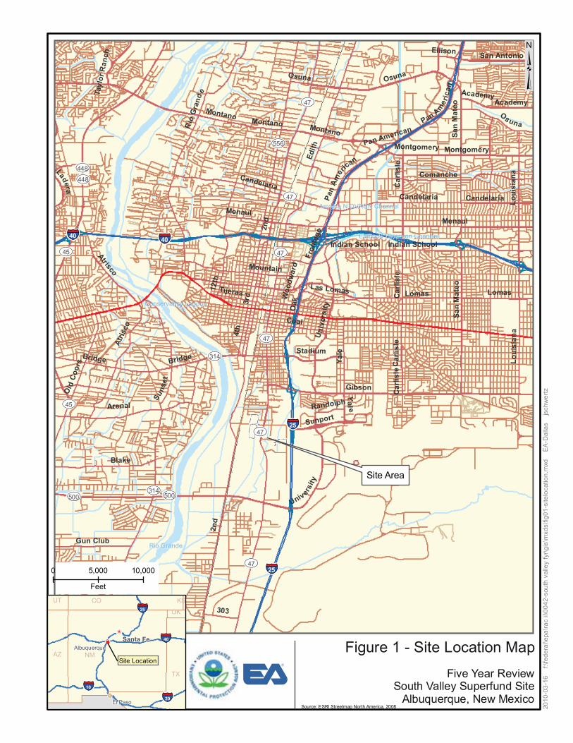
San
Ped
ro
a an
siiLo
u
o te a
MnSa
o te a
MnSa
a nis
Loui
Site Area
§̈¦40
§̈¦25
§̈¦40
§̈¦25
UV314
UV47
UV556
UV500
UV448
UV45
UV47
UV45
UV47
UV448
UV47
UV47
UV500
UV314
UV47
2nd
M e na ul
3rd
Edith
Gibs on
12th
Osuna
Rio
Gra
nde
Blake
a
Ya l eBridge
Arenal
4th
C o m a nc he
Suns
e t
Mountain
Coal
Montano
Car
lisle
M ont gom er y
Ca n d el a ri a
Fron
tage
Lom a s
Atrisco
303
Pan Amer
ican
Oak
Sunport
Universi
ty
Old
Coo
rs
G un C l ub
Ac a d em y
India n S c hool
Tijeras
Sa n A n t o n i o
S ta d i u m
Las Lomas
Ladera
Randolph
Ellison
Tayl
orR
anch
Woo
dwar
d
Montano
Pan American
Ca n d e l ar i aPan
Amer
ican
In dia n S c ho ol
Menaul Y
a l e
Univ
ers i
ty
Osuna
Ca r
li sleAt
risco
Mo n tg o m e ry
Bridge
Academy
Car
lisle
Montano
Lom a s
2nd
Candelaria
Osuna
Ca r
lis le
Rio GrandeRio Grande
Amafca N DVRSN ChannelAmafca N DVRSN Channel
Conservancy LagoonConservancy Lagoon
Embudo Diversion ChannelEmbudo Diversion Channel
0 5,000 10,000
Feet
Site Location
Sa n t a F e
El Paso
Albuquerque
§̈¦25
§̈¦40
§̈¦10
§̈¦20
NM
TX
AZ
COUT
OK
KS
³
2010
-03-
16
f:\fe
dera
l\epa
\rac
ii\00
42-s
outh
val
ley
fyr\g
is\m
xds\
fig01
-site
loca
tion.
mxd
E
A-D
alla
s js
chw
ertz
Figure 1 - Site Location Map
Five Year Review South Valley Superfund Site
Albuquerque, New Mexico Source: ESRI Streetmap North America, 2008

C
&
&
&
&
Albu
quer
que
Met
ropo
litan
Ar
royo
and
Flo
od C
ontro
l Aut
horit
ySo
uth
Div
ersi
on C
hann
el
³ CV-631 P83-27P
! ! CV-431
!
I-04 GM-23 &A
CV-641
<
&A P83-28P
!
GM-24S GM-24D
A&&A
<
! GM-10
&A GM-22R GM-22 &A &A
GM-17D GM-17S GM-16 GM-01A&&A
< VE-10 & &A A VE-9 k(!
!k( AW-231 UNIVAR Groundwater
! Treatment Plant P83-31SP83-31D2 !
! I-01P83-31M!
A&
<
GM-15D GM-15S
&A
PCA:
GM-11S GM-11D
<
&A GM-26
&A
Source: - Aerial photo from Earth Data Analysis Center, hosted by Open Geospatial Consortium.
GM-25 - Site data for GE OU from AXIS Group, July, 2009. -Site d ata for Univar USA, Inc. from ARCADIS, January, 2010.&A
UT CO KS
§̈ OK 150¦25 0 300 <
Feet
§Santa Fe 40 ̈¦ Legend: Figure 2 - Univar USA, Inc. -Albuquerque AZ NM CV-501 GM-9DSite Location Off-site Monitoring Well -Ot her Owners A Well Locations
&A A-01 k(!GM-02
VE-8&A &GM-06 A !k(
<
VE-11
RW-04 Univar USA, Inc
&AAW-241 RW-03
<&A&A
VE-7! CA:P
GM-21
!k( GM-14D GM-14S
CA:P
GM-13 VE-5
&AA&
<
&AA-02 RW-02k(! VE-6&A
GM-04 GM-09GM-19 VE-4VE-2 VE-3
<
!k(GM-05GM-03 &A VE-12
&A k!(
&A RW-01 &A P&AA:CGM-09S
&A
<
!k( !!kkAA&&!((
k( VE-1
GM-07
<
GM-08 &ACV-501
! UNIVAR VE-13
Vapor Extraction !(GM-20
&System Building k GM-27
A &A GM-12RHL-01 &A
2010
-04-
20
f:\fe
dera
l\epa
\rac
ii\0
042-
sout
h va
lley
fyr\g
is\m
xds\
fig02
_uni
var.m
xd
EA
-Dal
las
jsch
wer
tz
Facility Boundary ! Deep Monitoring Well
<
<TX HL-01 A
A
Five Year Review South Valley Superfund Site
VE-1 GM-20k!( Vapor Well A Shallow Monitoring Well USEPA Deep Monitoring Well
§̈¦ PRW-02 I-01 A:§20 ̈¦ Recovery Well USEPA Shallow Monitoring Well Albuquerque, New MexicoEl Paso
10

Albu
quer
que
Met
ropo
litan
Arro
yo a
nd F
lood
Con
trol A
utho
rity
Sout
h D
ivers
ion
Chan
nel
³P83-16S&A
P83-15S P83-05S& &A A
SEW-1P83-14S
P83-13S A& SEW-11 SMW-08&A& &&A AA SEW-5 P83-03S
Shallow Zone Aquifer Treatment Plant
P83-12S P83-02S P83-04SSEW-2 &A& && AAA
S-01 &A SMW-11 &A &A &ASMW-13 &&&AAAA&k!(
SEW-8SW-07 SIW-01&A SMW-14&ASEW-3 &A P83-01S
SMW-12 &A SMW-10&SW-08 A SMW-18 &A
&A SEW-4
General Electric Aviation
P83-18S&A
General Electric Aviation
P83-17S&A SEW-10 &AA&SW-08
SMW-16&SMW-19 A
SW-04 &&AA SW-03
SW-02 A A&&& ASMW-17
0 250 500 & S-04A
Feet Source: - Aerial photo from Earth Data Analysis Center, hosted byUT CO KS Univar USA, Inc Open Geospatial Consortium.
§̈¦25
§̈¦10
§̈¦20
2010
-04-
20
f:\fe
dera
l\epa
\rac
ii\0
042-
sout
h va
lley
fyr\g
is\m
xds\
fig03
_ge_
shal
low
.mxd
E
A-D
alla
s js
chw
ertz
-Site d ata for GE OU from AXIS Group, July, 2009.OK -Site d ata for Univar USA, Inc. from ARCADIS, January, 2010.
§̈¦40
Site Location & Monitoring Well Location & Extraction Well Location
Facility Boundary A
Water Level A
Shallow Zone Shallow Zone Ground Water Well Locations TX Five Year Review
Santa Fe Legend: Figure 3 - General Electric Aviation -Albuquerque AZ NM
El Paso &A
Water Quality and Water Level Monitoring Well Location k!(
Shallow Zone South Valley Superfund Site Injection Well Location Albuquerque, New Mexico

&Al
buqu
erqu
e M
etro
polita
n
Arro
yoan
d Fl
ood
Cont
rol A
utho
rity
Sout
h D
ivers
ion
Chan
nel
&
<
A
SJ6-10D ³(L*)
&A
SJ6-02D (L*)
&A MILES-01
DMW-03 (L)
&A
IMW-06 (L) Deep Zone Aquifer
Treatment Plant&A P83-10D (L) SJ6-01D IW-632
(L,Q*) (L,F)&AGeneral Electric && AA
WB-06 IW-642 P83-19M (L,Q)(L,F)
Aviation &A P83-19LR (L,Q)IW-641 (L,F)(L,Q*) &&IW-639 IW-633 & A P83-30D2 A P83-19U (L,Q)A &IW-631 (L,F)&&(L,F) A
&(L,F) A &A IW-640 (L,F)
&(L,Q) A
P83-19D2 (L,Q)
& A & P83-21 A&A
IW-638 A AD-01 (L,Q)(L,F) &(L,Q*) A &
P83-25A & (L,Q)I-07 A
(L) P83-08D SJ6-07D P83-29 P83-26 P83-22D (L,Q)(L) IW-637 (L*,Q*)&A (L,Q) &(L,Q) A P83-22M (L,Q)(L,F)& & SJ6-08D &A& &A P83-22S (L,Q)
(L*,Q*) A && &AA
A AA&
IW-638R A &
& EW-004 (L,Q,F)AHL-02 (L,F) A(L,Q) P83-22D2 (L,Q) IW-637R && A IW-639RA (L,F) WB-04
&A (L,Q)&A
I-03 (L) EW-001 &&& D-02 (L,Q) (L,Q,F)
WB-02 AAA
D-03 (L) (L,Q) EW-002 &A& (L,Q,F)AGeneral Electric &A WB-07 (L,Q) &A P83-23
P83-09 Aviation
EW-003 (L,Q) (L,Q) (L,Q,F)
&A& P83-24& AA (L,Q) IW-634P83-07 &
(L,Q) WB-01 EW-003R A (L,F) (L,Q) (L,Q,F) P83-27 &A&A (L,Q)& &A A IW-635DMW-01 DMW-02 I-04
& P83-28 (L,F)
& & &(L) (L,Q) P83-11 (L) A
A A &(L)
A (L,Q)
&AIW-636&A Notes:A (L,F) - (L) indicates ground water level monitoring will be conductedHL-05 (L) WB-05 - (Q) indicates water quality monitoring will be conducted&(L,Q) A -(F) ind icates flow rates will be monitored0 250 500 P83-31& * Well monitored during San Jose-6 event only()A I-06 &A
(L)Feet &A Source:&A - Aerial photo from Earth Data Analysis Center, hosted byUT CO KS Open Geospatial Consortium.Univar USA, Inc§̈¦25
2010
-04-
20
f:\fe
dera
l\epa
\rac
ii\0
042-
sout
h va
lley
fyr\g
is\m
xds\
fig04
_ge_
deep
.mxd
EA
-Dal
las
jsch
we
rtz
-Site d ata for GE OU from AXIS Group, July, 2009.OK -Site d ata for Univar USA, Inc. from ARCADIS, January, 2010
<
A
§̈¦
§̈¦
40
Site Location Legend: Deep Zone Ground Water Well Locations TX Five Year ReviewFacility Boundary & Monitoring Well Location & Injection Well LocationA A
20
Santa Fe Figure 4 - General Electric Aviation -Albuquerque AZ NM
§̈¦ South Valley Superfund Site & Extraction Well LocationA Municipal Pumping Well Albuquerque, New MexicoEl Paso
10

TABLES

TABLE 1 CHRONOLOGY OF SITE EVENTS SOUTH VALLEY SUPERFUND SITE, ALBUQUERQUE, NEW MEXICO
Date Event
1978
Volatile organic compounds were detected in City of Albuquerque wells from the San Jose and Miles municipal well fields. In subsequent sampling, contamination persisted in wells SJ-3 and SJ-6 (in the San Jose well field) whereas the impact in well Miles-1 (in the Miles well field) was not confirmed and it was returned to service.
1981 As pre-National Priorities List responses, City of Albuquerque took Albuquerque municipal wells SJ-3 and SJ-6 off-line.
8 September 1983 The South Valley Site is posted on the National Priorities List. 22 March 1985 The Record of Decision for OU 01 was signed.
28 September 2005 Approval of the FYR memorandum for the Site. Univar – Edmunds Street OUs (OU 03 and OU 04)
28 June 1988 OU 03 - Record of Decision for the Edmunds Street Ground Water OU is signed.
January 1989 Submittal of the Remedial Investigation and Feasibility Study reports to EPA and NMED.
30 March 1989 OU 04 – the Record of Decision for the Edmunds Street Property Source Control is signed.
27 March 1990 The Consent Decree in the Matter of the United States of America versus Univar Corporation was entered on docket.
7 September 1990 The Remedial Action Plan for OU 03 was submitted to the EPA and NMED. 1990 The construction of the ground water remedy at OU 03 was completed.
10 September 1990 through 14 January
1991 The ground water system for OU 03 startup program was conducted. 8 November 1995 The first FYR for the site was completed.
March 1996
EPA and NMED gave verbal approval of modifications to the ground water remedial system. These modifications included using Columbia Analytical Services as a laboratory, lower reporting limits, and elimination of analysis for benzene, toluene, ethylbenzene, and xylene and 1, 2- dichloroethane.
March 1998 Two ground water monitoring wells were installed, one as a replacement well (GM-22R) and one new well (GM-25).
November 1998 The vapor extraction system for OU 04 was installed. 16 July 1999 Air Quality Permit for the vapor extraction system was obtained. August 1999 Pilot Study started for the vapor extraction system.
14 September 2000 Second FYR report was completed.
October 2000 Complete the installation of additional vapor extraction system wells for full system build out.
15 July 2003
City of Albuquerque Environmental Health Department approved discontinuing the compliance sampling for the vapor extraction system (OU 04).
7 October 2004
Univar received authorization from EPA (Mr. Terry Roundtree) in an electronic communication to discontinue semi-annual sampling of the treatment unit influent and effluent and of the ground water monitoring wells and to reduce the number of ground water monitoring wells monitored annually.
31 January 2005 EPA letter requesting the installation of deeper wells.
Page 1 of 4

TABLE 1 CHRONOLOGY OF SITE EVENTS SOUTH VALLEY SUPERFUND SITE, ALBUQUERQUE, NEW MEXICO
(continued)
Date Event August 2005 Installation of wells GM-27 and GM-28.
2 September 2005 Third FYR report for Univar was completed. 7 September 2006 Work plan to optimize future remedial activities. 18 October 2006 EPA approval with change of the optimization plan for remedial activities.
29 September 2006 Vapor extraction system was shut down. 3 November 2006 Ground water treatment system was shut down.
5 December 2007 Information regarding the path forward following the implementation of the system optimization and revised remedial actions.
5 December 2007 Discussion regarding the results of the optimization study and revision of the remedial actions.
30 January 2008 EPA and NMED approval for the revised remedial action.
19 November 2009
Letter from EPA notifying Univar that they started the FYR for the South Valley Superfund site and alleviating concerns that Univar should perform this review consistent with the Consent Decree.
19 November 2009 Letter from EPA to Univar regarding sampling for 1,4-dioxane.
7 January 2010 Letter from ARCADIS on behalf of Univar responding to the EPA letter regarding sampling for 1,4-dioxane.
15 January 2010* Results of the October 2009 quarterly sampling of ground water monitoring wells.*
GEA – Plant 83/GE OUs (OU 02, OU 05, and OU 06) 1988 Remedial Investigation/Feasibility Study complete.
30 September 1988 The Record of Decision for OU 02, the vicinity of SJ-6 is signed
30 September 1988 Record of Decision for shallow soil and ground water (OU 05) and deep ground water (OU 06) is signed.
16 June 1989 The Administrative Order in the matter of General Electric Company, South Valley Superfund Site was entered on docket.
1991 Remedial design start for OU 05 soil vapor extraction system. 1992 Remedial design start for OU 05 Shallow Ground Water Remediation System. 1992 Remedial design complete for OU 05 soil vapor extraction system.
June 1992 Start of the remedial action for the shallow soils. 1994 Remedial design start for the Deep Zone Ground Water Remediation System. 1993 Final closeout report for OU 05 soil vapor extraction system.
1993 Remedial design complete for OU 05 Shallow Ground Water Remediation System.
May 1994 Remedial action start for the Shallow Ground Water Remediation System. 1995 Remedial design complete for Deep Zone Ground Water Remediation System.
March 1996 Deep Zone Ground Water Remediation System cold start and hot start and prove-out.
April 1996 April 1996 for Deep Zone Ground Water Remediation System dedication ceremony and full time operation.
September 2000 First FYR for GEA is completed. 2001 Optimization No. 1 for the Deep Zone Ground Water Remediation System
15 September 2005 Second FYR for GEA is completed.
15 August 2006 Submittal of the 2005-2006 annual reports for the shallow and deep aquifer remediation systems.
Page 2 of 4

TABLE 1 CHRONOLOGY OF SITE EVENTS SOUTH VALLEY SUPERFUND SITE, ALBUQUERQUE, NEW MEXICO
(continued)
Date Event
18 September 2006 GEA through their contractor submitted proposed changes in the October 2006 sampling.
22 September 2006 EPA response to proposed changes to the October 2006 sampling.
26 October 2006
Explanation of Significant Difference stipulates new Maximum Contaminant Level/applicable or relevant and appropriate requirement for tetrachloroethylene at 5 microgram per liter.
23 February 2007 EPA notification that 2 wells P83-08D and P83-08M need to be plugged and abandoned.
2 March 2007 Request for Comfort Letter for the owner of Duke City Distributing Co. property.
2 March 2007 EPA response to the request to plug and abandon P83-08D and P83-08M 9 March 2007 EPA provides Comfort Letter to the owner of neighboring property,
16 March 2007 GEA contractor proposal to plug and abandon P83-08D and P83-08M. 3 April 2007 GEA request to plug and abandon the two wells. 4 April 2007 EPA approval to plug and abandon wells P83-08D and P83-08M.
18 April 2007 EPA approval to change the April 2007 sampling event. 11 May 2007 NMED approves the renewal of the ground water discharge permit DP_1065. 5 July 2007 GEA provided EPA results for 1,4-dioxane.
15 August 2007 Submittal of the 2006-2007 annual reports for the shallow and deep aquifer remediation systems.
11 September 2007 GEA request to terminate operation of North Plant – shallow zone treatment.
24 October 2007 EPA response to GEA’s request for termination of operations at the North Plant shallow zone treatment giving conditional approval.
5 November 2007 GEA response to EPA’s conditions approval. 13 November 2007 EPA approves the changes proposed on 5 November.
31 October 2007 Operations of the shallow zone ground water treatment system for North Plant was terminated.
2 April 2008 GEA Letter work plan to optimize the Deep Zone system.
15 August 2008 Submittal of the 2007-2008 annual reports for the shallow and deep aquifer remediation systems.
17 October 2008 The concentration of 1,1-dichloroethane in well SEW-05 in North Plant 83 area exceeded the applicable or relevant and appropriate requirement.
21 October 2008 Submittal of the 2008 revision of the performance and compliance monitoring plan for both the shallow and deep zones treatment systems.
24 November 2008 The pump at SWE-05 within the North Plant treatment system is brought back into operation.
13 April 2009 GEA summary of discussion with EPA on the approach for wells SEW-10 and SW-08.
22 April 2009 EPA response to summary of discussion regarding wells SEW-10 and SW-08.
15 August 2009 Submittal of the 2008-2009 annual reports for the shallow and deep aquifer remediation systems.
October 2009 Operations at the North Plant 83 Area were ceased.
10 November 2009 Request to EPA for plugging and abandonment of wells within the North Plant 83.
Page 3 of 4

TABLE 1 CHRONOLOGY OF SITE EVENTS SOUTH VALLEY SUPERFUND SITE, ALBUQUERQUE, NEW MEXICO
(continued)
Date Event
19 November 2009
Letter from EPA notifying GEA that they started the FYR for the South Valley Superfund site and alleviating concerns that GEA should perform this review consistent with the Administrative Order.
19 November 2009 Letter from EPA to GEA regarding sampling for 1,4-dioxane.
15 February 2010 Submittal of the semiannual 2008-2009 reports for the shallow and deep aquifer remediation systems.
15 March 2010** Work Plan to Conduct a Chemical Injection Remediation Program Shallow Zone Aquifer SW-08 and SEW-05 Areas.**
* This document is discussed further in this report as it presents data for the October 2009 sampling event.
** This document will not be discussed further in this report as it falls outside of the period of review for the FYR.
Notes: EPA U.S. Environmental Protection Agency. FYR Five-Year Review. GEA General Electric Aviation. NMED New Mexico Environment Department. OU Operable unit. Univar Univar USA, Inc.
Page 4 of 4

TABLE 2 UNIVAR USA, INC. PERCHLOROETHENE THRESHOLD CONCENTRATION VALUES
SOUTH VALLEY SUPEFUND SITE, ALBUQUERQUE, NEW MEXICO
Well April 2006 Perchloroethene
Concentration (μg/L) Threshold Criteria*
(μg/L) GM-01 4.1 6.1 GM-02 7.9 11.8 GM-9S 1.9 5.0
GM-11S 12 18 GM-13 6.2 9.3
GM-14S Not sampled 5.0 GM-14D Not sampled 5.0 GM-15S Not sampled 5.0 GM-21 12 18 GM-22 2.5 5.0
GM-22R <1 5.0 GM-25 Not sampled 5.0 GM-27 8.9 13.3
I-01 4.9 7.3 RW-02 1.1 5.0 RW-03 1.7 5.0 RW-04 2.6 5.0 * The threshold values are calculated as a 50 percent increase in perchloroethene concentrations from the April 2005 sampling event or 5 μg/L, whichever is greater; exceedances of these threshold values would trigger the restart of the treatment system.
Note: μg/L Micrograms per liter.

TABLE 3 ANNUAL OPERATION AND MAINTENANCE COSTS SOUTH VALLEY SUPEFUND SITE, ALBUQUERQUE, NEW MEXICO
Year Total Operation and Maintenance Cost ($)
Univar USA, Inc.* 2005 19,812 2006 27,796 2007 3,052 2008 5,875 2009 871
Total Univar 57,406 General Electric Aviation
2005 719,582 2006 600,247 2007 940,268 2008 2,627,819 2009 473,284
Total GEA 5,361,200 Site Total 5,450,604
* Reflects only the ground water system costs
Notes: GEA General Electric Aviation Univar Univar USA, Inc.

TABLE 4 CONCENTRATIONS OF 1,4-DIOXANE IN UNIVAR USA, INC. WELLS SOUTH VALLEY SUPEFUND SITE, ALBUQUERQUE, NEW MEXICO
Well
1,4-Dioxane Concentration (micrograms per liter) 4/11/05 to
4/13/05 9/7/05 4/3/06 10/8/08 1/26/09 to
1/27/09 10/14/09 to
10/15/09 A-01 20 J -- -- < 1.0 J < 1.0 J < 1.0 J GM-01 31 J -- -- -- -- --GM-02 28 -- -- 16 14 J 12 J GM-9S 16 J -- -- -- -- --GM-11S 28 -- -- 44 44 54 GM-11S-duplicate -- -- -- 45 43 --GM-12R* 16 -- -- -- -- --GM-13 33 -- -- 110 JD 120 J 160 GM-13-duplicate 32 -- -- -- -- --GM-14D -- -- -- --- --- 16 GM-14D-duplicate -- -- -- -- -- 15 GM-14S -- -- -- -- -- < 1.0 GM-15D -- -- -- -- -- 4.3 GM-15S -- -- -- -- -- <1.0 GM-21 26 J -- -- 23 23 J 24 GM-22R 5.2 J -- -- -- -- --GM-27 -- 22 -- 21 19 J 20 GM-28 -- 5.7 -- -- -- --GM-28-duplicate -- 5.8 -- -- -- --I-01 41 -- -- -- -- --RW-01 25 J -- -- -- -- --RW-02 27 J -- -- -- -- --RW-03 25 J -- -- -- -- --RW-04 17 J -- -- -- -- --TUE 22 J -- -- -- -- --TUI 22 J -- 18 -- -- --TUI-duplicate -- -- 20 -- -- --
* GM-12R was abandoned on 8 September 2005.
Notes: J Estimated value. D Diluted Dashes (--) sample was not analyzed for 1,4-dioxane

TABLE 5 CONCENTRATIONS OF SITE-RELATED VOCS IN SAMPLES FROM RECOVERY AND MONITORING WELLS AT UNIVAR BETWEEN SEPTEMBER 2005 AND OCTOBER 2009
SOUTH VALLEY SUPERFUND SITE, ALBUQUERQUE, NEW MEXICO
Well No.
Site-Related VOCs (ug/L)
Date Sampled
09/07/05 01/13/06
04/03/06 to
04/05/06 07/18/06 10/04/06
02/05/07 to
02/09/07
04/09/07 to
04/12/07 07/12/07
10/15/07 to
10/18/07 4/2/2008 10/8/2008
1/26/2009 to
1/27/2009 4/7/2009 8/4/2009
10/14/200 9 to
10/15/200
A-01 1,1-DCE 1,1,1-TCA TCE PCE
--------
--------
< 1 < 1 < 1 < 1
--------
--------
--------
< 1 < 1 < 1 < 1
--------
--------
--------
< 1 < 1 < 1 < 1
< 1 < 1 < 1 < 1
< 1 < 1 < 1 < 1
< 1.0 < 1.0 < 1.0 < 1.0
< 1.0 < 1.0 < 1.0 < 1.0
GM-01 1,1-DCE 1,1,1-TCA TCE PCE
--------
--------
< 1 < 1 < 1
4.1 J
--------
--------
< 1 < 1 < 1
2.5
< 1 < 1
1 3.3
--------
< 1 < 1 < 1
2.5
--------
--------
--------
--------
--------
--------
GM-02 (threshold
criteria 11.8)
1,1-DCE 1,1,1-TCA TCE PCE
--------
--------
< 1 < 1
1.8 J 7.9 J
--------
--------
< 1 < 1
2.5 8.8
< 1 < 1
1.9 7.0
--------
< 1 < 1
1.4 5.1
< 1 < 1
1.4 4.9
< 1 < 1
1.1 4.5
< 1 < 1
1.5 5.1
< 1 < 1
1.1 3.7
< 1.0 < 1.0
1.3 3.4
< 1.0 < 1.0
2.1 6.0
GM-09S 1,1-DCE 1,1,1-TCA TCE PCE
--------
--------
< 1 < 1 < 1
1.9 J
--------
--------
< 1 < 1 < 1 < 1
< 1 < 1 < 1
1.1
--------
< 1 < 1 < 1
1.7
--------
--------
--------
--------
--------
--------
GM-11S (threshold
criteria 18.0)
1,1-DCE 1,1,1-TCA TCE PCE
--------
--------
1.1 J < 1
3.1 J 12 J
--------
--------
< 1 < 1
2.4 8.1
< 1 < 1
2.5 8.1
--------
< 1 < 1
2.6 7.0
< 1 < 1
1.6 5.5
< 1 < 1 < 1
4.0
< 1 < 1 < 1
3.6
< 1 < 1 < 1
2.4
< 1.0 < 1.0 < 1.0
2.2
< 1.0 < 1.0 < 1.0
2.0
GM-13 (threshold
criteria 9.3)
1,1-DCE 1,1,1-TCA TCE PCE
--------
--------
< 1 < 1
1.4 J 6.2 J
--------
--------
< 1 < 1
1.6 5.4
< 1 < 1
1.3 4.9
--------
< 1 < 1 < 1
2.3
< 1 < 1 < 1
1.8
< 1 < 1 < 1
2.4
< 1 < 1 < 1
2.9
< 1 < 1 < 1
2.1
< 1.0 < 1.0 < 1.0
1.8
< 1.0 < 1.0 < 1.0
2.6
GM-14D 1,1-DCE 1,1,1-TCA TCE PCE
--------
--------
--------
--------
--------
< 1 < 1 < 1 < 1
< 1 < 1 < 1
4.4
< 1 < 1 < 1 < 1
< 1 < 1 < 1 < 1
--------
--------
--------
--------
--------
< 1.0 < 1.0 < 1.0 < 1.0
GM-14S 1,1-DCE 1,1,1-TCA TCE PCE
--------
--------
--------
--------
--------
< 1 < 1 < 1 < 1
< 1 < 1 < 1 < 1
< 1 < 1 < 1 < 1
1.1 < 1 < 1 < 1
--------
--------
--------
--------
--------
1.2 < 1.0 < 1.0 < 1.0
GM-15D 1,1-DCE 1,1,1-TCA TCE PCE
--------
--------
--------
--------
--------
< 1 < 1 < 1 < 1
< 1 < 1 < 1 < 1
--------
< 1 < 1 < 1 < 1
--------
--------
--------
--------
--------
< 1.0 < 1.0 < 1.0 < 1.0
GM-15S 1,1-DCE 1,1,1-TCA TCE PCE
--------
--------
--------
--------
--------
< 1 < 1 < 1 < 1
< 1 < 1 < 1 < 1
--------
< 1 < 1 < 1 < 1
--------
--------
--------
--------
--------
< 1.0 < 1.0 < 1.0 < 1.0
GM-21 (threshold
criteria 18.0)
1,1-DCE 1,1,1-TCA TCE PCE
--------
--------
< 1 < 1
4.3 J 12 J
--------
--------
< 1 < 1 < 1
3.6
< 1 < 1
1.6 4.8
--------
< 1 < 1
1.1 3.6
< 1 < 1 < 1
2.7
< 1 < 1 < 1
1.7
< 1 < 1 < 1
2.1
< 1 < 1
1.0 2.6
< 1.0 < 1.0 < 1.0
2.7
< 1.0 < 1.0 < 1.0
3.0
GM-22 1,1-DCE 1,1,1-TCA TCE PCE
--------
--------
< 1 < 1
1.2 J 2.5 J
--------
--------
< 1 < 1 < 1
1.6
< 1 < 1
1.2 2.7
--------
< 1 < 1
1.1 1.8
--------
--------
--------
--------
--------
--------
GM-22R 1,1-DCE 1,1,1-TCA TCE PCE
--------
--------
< 1 < 1 < 1 < 1
--------
--------
< 1 < 1 < 1 < 1
< 1 < 1 < 1 < 1
--------
< 1 < 1 < 1 < 1
--------
--------
--------
--------
--------
--------
GM-25 1,1-DCE 1,1,1-TCA TCE PCE
--------
--------
--------
--------
--------
< 1 < 1 < 1 < 1
< 1 < 1 < 1 < 1
--------
< 1 < 1 < 1 < 1
--------
--------
--------
--------
--------
--------
GM-27 (threshold
criteria 13.3)
1,1-DCE 1,1,1-TCA TCE PCE
< 1 < 1
3.3 8.1
--------
< 1 < 1
3.0 J 8.9 J
--------
--------
< 1 < 1 < 1
3.1
< 1 < 1
1.6 3.8
--------
< 1 < 1
1.4 3.8
< 1 < 1
1.1 2.2
< 1 < 1
1.1 3.1
< 1 < 1
1.3 2.4
< 1 < 1
1.0 2.5
< 1.0 < 1.0 < 1.0
2.0
< 1.0 < 1.0 < 1.0
1.9
GM-28 1,1-DCE 1,1,1-TCA TCE PCE
< 1 < 1 < 1 < 1
< 1 < 1 < 1 < 1
< 1 < 1 < 1 < 1
< 1 < 1 < 1 < 1
< 1 < 1 < 1 < 1
< 1 < 1 < 1 < 1
< 1 < 1 < 1 < 1
< 1 < 1 < 1 < 1
--------
--------
--------
--------
--------
--------
--------
I-01 1,1-DCE 1,1,1-TCA TCE PCE
--------
--------
< 1 < 1
1.3 J 4.9 J
--------
--------
< 1 < 1
1.4 4.6
< 1 < 1 < 1
2.7
--------
< 1 < 1
1.3 3.0
--------
--------
--------
--------
--------
--------
RW-01 1,1-DCE 1,1,1-TCA TCE PCE
--------
--------
< 1 < 1 < 1 < 1
--------
--------
--------
< 1 < 1 < 1 < 1
--------
--------
--------
--------
--------
--------
--------
--------
RW-02 1,1-DCE 1,1,1-TCA TCE PCE
--------
--------
< 1 < 1 < 1
1.1 J
--------
--------
< 1 < 1 < 1 < 1
< 1 < 1 < 1 < 1
--------
< 1 < 1 < 1 < 1
--------
--------
--------
--------
--------
--------
Page 1 of 5

TABLE 5 CONCENTRATIONS OF SITE-RELATED VOCS IN SAMPLES FROM RECOVERY AND MONITORING WELLS AT UNIVAR BETWEEN SEPTEMBER 2005 AND OCTOBER 2009
SOUTH VALLEY SUPERFUND SITE, ALBUQUERQUE, NEW MEXICO
Well No.
Site-Related VOCs (ug/L)
Date Sampled
09/07/05 01/13/06
04/03/06 to
04/05/06 07/18/06 10/04/06
02/05/07 to
02/09/07
04/09/07 to
04/12/07 07/12/07
10/15/07 to
10/18/07 4/2/2008 10/8/2008
1/26/2009 to
1/27/2009 4/7/2009 8/4/2009
10/14/200 9 to
10/15/200
RW-03 1,1-DCE 1,1,1-TCA TCE PCE
--------
--------
< 1 < 1 < 1
1.7 J
--------
--------
< 1 < 1 < 1 < 1
< 1 < 1 < 1 < 1
--------
< 1 < 1 < 1 < 1
--------
--------
--------
--------
--------
--------
RW-04 1,1-DCE 1,1,1-TCA TCE PCE
--------
--------
< 1 < 1 < 1
2.6 J
--------
--------
< 1 < 1 < 1
1
< 1 < 1 < 1
1.3
--------
< 1 < 1 < 1
1.6
--------
--------
--------
--------
--------
-------- v te
Notes: ug/L DCE TCA TCE PCE Univar VOC
microgram per liter dichloroethene trichloroethane trichloroethene tetrachloroethene Univar USA, Inc. volatile organic compound
Page 2 of 5

TABLE 6 GEA SHALLOW ZONE AQUIFER TREATMENT SYSTEM INFORMATION SOUTH VALLEY SUPERFUND SITE, ALBUQUERQUE, NEW MEXICO
Timeframe
Volume of Ground Water Treated
(gallons) Approximate Mass of
VOCs Removed (grams) Reference
July 2005 through June 2006 40,034 0.6 Aestus 2006a
July 2006 through June 2007 60,591 0.4 Axis 2007a
2007 through June 2008 44,382 0.2 Axis 2008b
2008 through June 2009 41,212 1 Axis 2009c
July through December 2009 15,021 <1 Axis 2010b
Notes: Aestus Axix GEA VOC
Aestus, Inc. Axis Group, Inc. General Electric Aviation Volatile organic compound

TABLE 7 GEA DEEP ZONE AQUIFER TREATMENT SYSTEM INFORMATION SOUTH VALLEY SUPERFUND SITE, ALBUQUERQUE, NEW MEXICO
Timeframe Volume of Water Injected (gallons)
Volume of Water
Extracted (gallons)
Average Monthly Mass Removed
(pounds) Total Mass VOCs Removed (pounds)
Efficiency of Treatment Plant
(%) Reference 1 July 2005 through
30 June 2006 454,780,575 457,953,158 3.9 47 97 Aestus 2006b
1 July 2006 through 30 June 2007 439,318,045 440,948,173 2.9 34.6 95
Axis 2007b
1 July 2007 through 30 June 2008 362,467,440 358,526,404 1.6 19.4 90
Axis 2008c
1 July 2008 through 30 June 2009 325,230,036 322,331,331 1.3 15.6 97
Axis 2009c
1 July through 31 December 2009 23,421,661 23,487,769 Not specified Not specified Not specified
Axis 2010b
Notes: Aestus Aestus, Inc Axis Axis Group, Inc. GEA General Electric Aviation VOC Volatile organic compound

TABLE 8 COMPARISON OF ARARS TO CURRENT DRINKING WATER STANDARDS FOR UNIVAR USA, INC. OPERABLE UNIT 03
SOUTH VALLEY SUPERFUND SITE, ALBUQUERQUE, NEW MEXICO
Constituent
Cleanup Goal from Record of Decision or Explanation of
Significant Difference (µg/L) Current Standards (µg/L)
Concentration Source Clean Water Act
(MCL) NMWQCC
Acetone No standard listed Not applicable Not applicable Not applicable Carbon tetrachloride 5 MCL 5 10 Chloroform 100 NMWQCC Not applicable 100 1,2-dichloroethane 5 MCL 5 10
Trans-1,2-dichloroethene 70 MCL Goal 100 Not applicable 1,1-dichloroethene 5 NMWQCC 7 5 Methylene chloride 100 NMWQCC Not applicable Not applicable Perchloroethylene 5* MCL 5 20 1,1,1-trichloroethane 60 NMWQCC 200 60 Trichloroethane 5 MCL 5 100 * The initial ARAR for tetrachloroethene was set as 20 μg/L, based on NMWQCC standards (based on
New Mexico Administrative Code, various dates); this ARAR was modified in a 2006 Explanation of Significant Differences (EPA 2006a) to reflect the MCL of 5 μg/L promulgated in 1992.
Notes: ARAR Applicable or relevant and appropriate requirement. μg/L Microgram per liter. MCL Maximum Contaminant Level. NMWQCC New Mexico Water Quality Control Commission.

TABLE 9 COMPARISON OF ARARS TO CURRENT DRINKING WATER STANDARDS FOR GEA OPERABLE UNITS
SOUTH VALLEY SUPERFUND SITE, ALBUQUERQUE, NEW MEXICO
Constituent Cleanup Goal
(µg/L)
Current Standards (µg/L)
Clean Water Act (Maximum Contaminant Level)
New Mexico Water Quality Control
Commission 1,1,1-Trichloroethane 60 200 60 1,1,2,2-Tetrachloroethane 10 -- 10 1,1,2-Trichloroethane 5 5 10 1,1-Dichloroethane 25 -- 25 1,1-Dichloroethene 5 7 5 1,2-Dichloroethane 5 5 10 1,2-Dichloropropane 5 5 --2-Chloroethyl vinyl ether -- -- --2-Hexanone -- -- --4-Methyl 2-pentanone -- -- --Acetone -- -- --Benzene 5 5 10 Bromoform 80 80* Bromomethane -- -- --Carbon disulfide -- -- --Carbon tetrachloride 5 5 10 Chlorobenzene 80 100 --Chloroethane -- -- --Chloroform 80 80* 100 Chloromethane 2,300,000 -- --cis-1,3-Dichloropropene -- -- --Dibromochloromethane 80 80* --Dichlorobromomethane 80 80* --Ethylbenzene 700 700 750 Ethylene dibromide 0.5 0.05 0.1 Methyl ethyl ketone (2-butanone) -- -- --Methyl tertiary butyl ether 100 Not applicable Not applicable Methylene chloride 5 Not applicable Not applicable Tetrachloroethene 5 5 20 Toluene 750 1,000 750 trans-1,2-Dichloroethene 100 100 Not applicable trans-1,3-Dichloropropene -- -- --Trichloroethene 5 5 100 Trichlorofluoromethane -- -- --Vinyl chloride 1 2 1 Xylenes (total) 620 10,000 620
* 80 milligrams per liter is the Maximum Contaminant Level for Total trihalomethanes.
Notes: ARAR = Applicable or relevant and appropriate requirement. GEA = General Electric Aviation μg/L = Microgram per liter. Dashes (--) indicate no standard listed.

Continue sampling for this compound at OU 03 (Univar); determine if 1,4dioxane needs to be added as a contaminant of concern for this OU and if so, evaluate potential cleanup goal and remedial action. Determine whether further sampling for 1,4-dioxane is required at OUs 05 and 06 (GEA).
TABLE 10 RECOMMENDATIONS AND FOLLOW UP ACTIONS SOUTH VALLEY SUPERFUND SITE, ALBUQUERQUE, NEW MEXICO
Follow Up Actions: Affects Remedy
Protectiveness (Yes/No) Issue
Recommendations and Follow Up Actions
Party Responsible
Oversight Agency
Milestone Date Current Future
1,4-Dioxane – This compound is known to have been used as a stabilizer in solvent at Univar. Its presence above certain levels could affect the future protectiveness of the ground water remedy at OU 03 at this facility. While the quantitative and qualitative risk data for this compound are still in development, a path forward for evaluation should be determined for this compound.
-Univar and
GEA EPA 2011 No Yes
Ethylene Dibromide – at OUs 05 and 06 (GEA), the current MCL and NMWQCC standards for ethylene dibromide are lower than the standards established in the Performance and Compliance Monitoring Plan; in addition, some of the laboratory analyses used for detecting this compound had detection limits higher than the ARAR and ground water discharge permit requirement of 0.05 μg/L.
For OUs 05 and 06 (GEA), the Performance and Compliance Monitoring Plan should be updated to satisfy the current Maximum Contaminant Level for this compound (0.05 μg/L); analytical methods should be selected to consistently meet the ARAR and the ground water discharge permit requirement of 0.05 μg/L
Univar and GEA
EPA For OU 03, prior to next
sampling event; for
OUs 05 and 06, 2011
No Yes
Page 1 of 3

TABLE 10 RECOMMENDATIONS AND FOLLOW UP ACTIONS SOUTH VALLEY SUPERFUND SITE, ALBUQUERQUE, NEW MEXICO
Issue Recommendations and
Follow Up Actions Party
Responsible Oversight
Agency Milestone
Date
Follow Up Actions: Affects Remedy
Protectiveness (Yes/No) Current Future
MTBE – concentrations for MTBE had a sharp increase in wells P83-27S and P83-28P at OU 06; although MTBE is not a contaminant related to the operations at GEA, it is associated with releases of petroleum products at sites being addressed by the NMED GWQB; this concentration increase may indicate the plumes of petroleum hydrocarbons remediated at the adjacent sites may not be contained at the depth where these wells are screened within the Deep Zone Aquifer.
Notify Respondents of the First Amended Unilateral Administrative Order (CERCLA-VI-14-91, Oct. 8, 1991) and the New Mexico Environment Department (NMED) Groundwater Quality Bureau of information that shows the migration of MTBE in the Deep Zone Aquifer at the GEA site from offsite sources. This information indicates that plumes of petroleum hydrocarbons, currently being remediated at the adjacent sites under the regulatory authority of NMED, may not be contained in the Deep Zone Aquifer.
EPA EPA January 2011
No No
Public Outreach – Site surveys indicate that regular updates containing information related to the current status of the Site activities would be useful to the surrounding community. In addition, the public is concerned with the fact that the GEA facility is slated for closure in the near future and the consequences of this closure on the implementation of the remedies at the GEA OUs.
Increase the frequency of public updates and dissemination of information concerning the progress of the remedy at the Site would be useful to the surrounding community. In addition, communication of GEA’s continued commitment to complete the cleanup of the OUs for which they are responsible, should alleviate concerns that cleanup will be impacted by GEA closing the facility in Albuquerque.
EPA EPA January 2011
No No
Page 2 of 3

TABLE 10 RECOMMENDATIONS AND FOLLOW UP ACTIONS SOUTH VALLEY SUPERFUND SITE, ALBUQUERQUE, NEW MEXICO
Follow Up Actions: Affects Remedy
Protectiveness (Yes/No) Issue
Recommendations and Follow Up Actions
Party Responsible
Oversight Agency
Milestone Date Current Future
TCE and 1,1-DCE Concentrations in Deep Zone Aquifer – at OU 06, TCE concentrations are on an upward trend since May 2007 and 1,1-DCE concentrations are on an upward trend since May 2008 in Westbay well WB-02 in the 4,500-4,600 ft amsl horizon; it is unclear whether extraction well EW-002 is capturing the contamination in WB-02(4). The number of monitoring wells screened in this horizon limit adequate characterization.
Further evaluation should be performed of the extent of the impact of TCE and 1,1-DCE within this depth horizon and the ability of the current system to address the impact in well WB-02(4) in a timely and effective manner; the capture of the contamination in WB-02(4) by extraction well EW-002 should be further documented; the number of monitoring wells screened in this horizon should be adequate to delineate the impact in this horizon, as well as determine the potentiometric surfaces and outline capture zones; innovative technologies should be reviewed to address remediation of OU 06.
EPA EPA April 2011 No Yes
Notes: amsl Above mean sea level μg/L Micrograms per liter. GEA General Electric Aviation MCL Maximum Contaminant Level
NMED New Mexico Environment Department NMWQCC New Mexico Water Quality Control Commission OU Operable unit Univar Univar, USA, Inc.
Page 3 of 3

ATTACHMENT 1
DOCUMENTS REVIEWED

Documents Reviewed South Valley Superfund Site Fourth Five-Year Review
Aestus. 2006a. 2005-2006 Annual Report and Semi-Annual Quality Assurance Report Shallow Zone Groundwater Remediation System Former Air Force Plant 83/General Electric Operable Unit South Valley Superfund Site, Albuquerque, New Mexico. 15 August.
Aestus. 2006b. 2005-2006 Annual Report and Semi-Annual Quality Assurance Report Deep Zone Groundwater Remediation System Former Air Force Plant 83/General Electric Operable Unit South Valley Superfund Site, Albuquerque, New Mexico. 15 August.
Aestus. 2006c. Letter Proposing Changes to the October Sample Event GE/Plant 83 Superfund Site, Albuquerque, New Mexico. 18 September.
American Ground-Water Consultants. 1983. Hydrogeology of the AmeriGas Property, Albuquerque, New Mexico: Prepared for Counsel to AmeriGas, Inc., Valley Forge Pennsylvania.
ARCADIS. 2005a. Third Five-Year Review of Remedial Actions, Univar USA, Inc. 3301 Edmunds Street Site, Albuquerque, New Mexico. 2 September.
ARCADIS. 2005b. Letter Report to Mr. Gregg Lyssy, U.S. Environmental Protection Agency Regarding Installation of Two Additional Groundwater Monitoring Wells and Abandonment of Two Groundwater Monitoring Wells Univar USA Inc. 3301 Edmunds Street Site Albuquerque, New Mexico. 21 December.
ARCADIS. 2006a. 2006 Annual Progress Report for Remedial Actions, Univar USA Inc. 3301 Edmunds Street Site Albuquerque, New Mexico. 14 July.
ARCADIS. 2006b. Work Plan to Optimize the Future Remedial Activities, Univar USA, Inc. 3301 Edmunds Street Site, Albuquerque, New Mexico. 7 September.
ARCADIS. 2007. February 2007 Quarterly Sampling of Groundwater Monitoring Wells Univar USA Inc. 3301 Edmunds Street Site, Albuquerque, New Mexico. 19 March.
ARCADIS. 2008. Letter Summarizing the 5 December 2007, Meeting with EPA. 28 January.
ARCADIS. 2010a. Letter from Ms. Kathryn Brantingham of ARCADIS to Mr. Michael Hebert of EPA, in Response to EPA Letter Regarding 1,4-Dioxane. 7 January.
ARCADIS. 2010b. October 2009 Quarterly Sampling of Groundwater Monitoring Wells, Univar USA, Inc, 3301 Edmunds Street, Albuquerque, New Mexico. 15 January.
Axis Group, Inc. (Axis). 2007a. 2006-2007 Annual Report and Semi-Annual Quality Assurance Report Shallow Zone Groundwater Remediation System Former Air Force Plant 83/General Electric Operable Unit, South Valley Superfund Site Albuquerque, New Mexico. 15 August.
Axis. 2007b. 2006-2007 Annual Report and Semi-Annual Quality Assurance Report Deep Zone Groundwater Remediation System Former Air Force Plant 83/General Electric Operable Unit, South Valley Superfund Site Albuquerque, New Mexico. 15 August.
Page 1 of 6

Documents Reviewed South Valley Superfund Site Fourth Five-Year Review
Axis. 2007c. Request to Terminate North Plant 83 Operations. Shallow Zone Groundwater Remediation System. 11 September.
Axis. 2007d. Approval Letter to Terminate North Plant 83 Operations Shallow Zone Groundwater Remediation System. 5 November.
Axis. 2008a. Letter Work Plan to Optimize the Deep Zone Groundwater Remediation System. 2 April.
Axis. 2008b. 2007-2008 Annual Report and Semi-Annual Quality Assurance Report Shallow Zone Groundwater Remediation System Former Air Force Plant 83/General Electric Operable Unit South Valley Superfund Site Albuquerque, New Mexico. 15 August.
Axis. 2008c. 2007-2008 Annual Report and Semi-Annual Quality Assurance Report Deep Zone Groundwater Remediation System Former Air Force Plant 83/General Electric Operable Unit South Valley Superfund Site Albuquerque, New Mexico. 15 August.
Axis. 2008d. Performance and Compliance Monitoring Plan Revision 2008 Deep Zone and Shallow Zone Groundwater Remediation Systems Former Air Force Plant 83/General Electric Operable Unit South Valley Superfund Site Albuquerque, New Mexico. 21 October.
Axis. 2009a. Transmittal Updated 2/17/09 - Performance and Compliance Monitoring Plan - Revision 2008 Deep Zone and Shallow Zone Groundwater Remediation Systems Former Air Force Plant 83/General Electric Aviation Operable Unit South Valley Superfund Site Albuquerque, New Mexico. 17 February.
Axis. 2009b. Follow-Up to Conference Call Shallow Zone Groundwater Extraction Well and SEW-10 and Monitoring Well SW-08. 13 April.
Axis. 2009c. 2008-2009 Annual Report and Semi-Annual Quality Assurance Report Shallow Zone Groundwater Remediation System Former Air Force Plant 83/General Electric Operable Unit South Valley Superfund Site Albuquerque, New Mexico. 15 August.
Axis. 2009d. 2008-2009 Annual Report and Semi-Annual Quality Assurance Report Deep Zone Groundwater Remediation System Former Air Force Plant 83/General Electric Operable Unit South Valley Superfund Site Albuquerque, New Mexico. 15 August.
Axis. 2009e. Request to Implement Closure Plan North Plant 83 Area Wells Former Plant 83/GE Operable Unit Albuquerque, New Mexico. 10 November.
Axis. 2010a. 2009 Semi-Annual Report, Third and Fourth Quarters-Quality Assurance Report Shallow Zone Groundwater Remediation System Former Air Force Plant 83/General Electric Operable Unit South Valley Superfund Site Albuquerque, New Mexico. 15 February.
Axis. 2010b. 2009 Semi-Annual Report, Third and Fourth Quarters-Quality Assurance Report Deep Zone Groundwater Remediation System Former Air Force Plant 83/General Electric Operable Unit South Valley Superfund Site Albuquerque, New Mexico. 15 February.
Axis. 2010c. Work Plan to Conduct a Chemical Injection Remediation Program, Shallow Zone Aquifer SW-08 and SEW-05 Areas Former Plant 83/GE Operable Unit, South Valley Superfund Site. 15 March.
Page 2 of 6
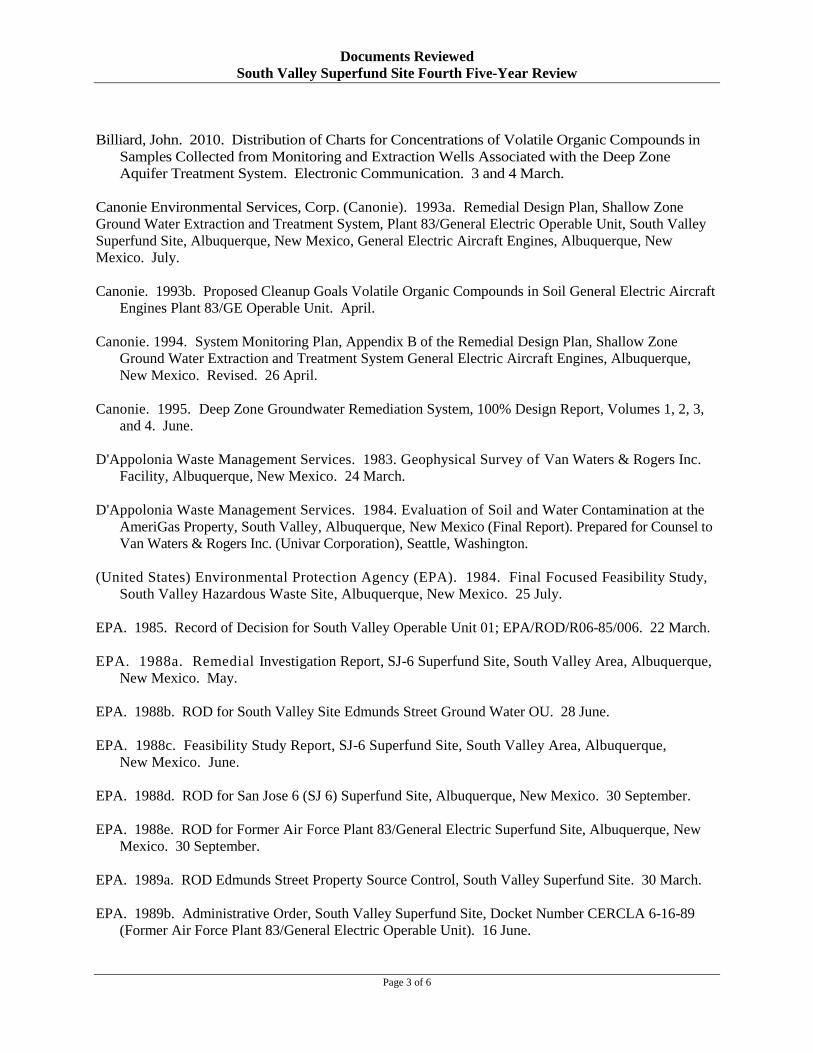
Documents Reviewed South Valley Superfund Site Fourth Five-Year Review
Billiard, John. 2010. Distribution of Charts for Concentrations of Volatile Organic Compounds in Samples Collected from Monitoring and Extraction Wells Associated with the Deep Zone Aquifer Treatment System. Electronic Communication. 3 and 4 March.
Canonie Environmental Services, Corp. (Canonie). 1993a. Remedial Design Plan, Shallow Zone Ground Water Extraction and Treatment System, Plant 83/General Electric Operable Unit, South Valley Superfund Site, Albuquerque, New Mexico, General Electric Aircraft Engines, Albuquerque, New Mexico. July.
Canonie. 1993b. Proposed Cleanup Goals Volatile Organic Compounds in Soil General Electric Aircraft Engines Plant 83/GE Operable Unit. April.
Canonie. 1994. System Monitoring Plan, Appendix B of the Remedial Design Plan, Shallow Zone Ground Water Extraction and Treatment System General Electric Aircraft Engines, Albuquerque, New Mexico. Revised. 26 April.
Canonie. 1995. Deep Zone Groundwater Remediation System, 100% Design Report, Volumes 1, 2, 3, and 4. June.
D'Appolonia Waste Management Services. 1983. Geophysical Survey of Van Waters & Rogers Inc. Facility, Albuquerque, New Mexico. 24 March.
D'Appolonia Waste Management Services. 1984. Evaluation of Soil and Water Contamination at the AmeriGas Property, South Valley, Albuquerque, New Mexico (Final Report). Prepared for Counsel to Van Waters & Rogers Inc. (Univar Corporation), Seattle, Washington.
(United States) Environmental Protection Agency (EPA). 1984. Final Focused Feasibility Study, South Valley Hazardous Waste Site, Albuquerque, New Mexico. 25 July.
EPA. 1985. Record of Decision for South Valley Operable Unit 01; EPA/ROD/R06-85/006. 22 March.
EPA. 1988a. Remedial Investigation Report, SJ-6 Superfund Site, South Valley Area, Albuquerque, New Mexico. May.
EPA. 1988b. ROD for South Valley Site Edmunds Street Ground Water OU. 28 June.
EPA. 1988c. Feasibility Study Report, SJ-6 Superfund Site, South Valley Area, Albuquerque, New Mexico. June.
EPA. 1988d. ROD for San Jose 6 (SJ 6) Superfund Site, Albuquerque, New Mexico. 30 September.
EPA. 1988e. ROD for Former Air Force Plant 83/General Electric Superfund Site, Albuquerque, New Mexico. 30 September.
EPA. 1989a. ROD Edmunds Street Property Source Control, South Valley Superfund Site. 30 March.
EPA. 1989b. Administrative Order, South Valley Superfund Site, Docket Number CERCLA 6-16-89 (Former Air Force Plant 83/General Electric Operable Unit). 16 June.
Page 3 of 6

Documents Reviewed South Valley Superfund Site Fourth Five-Year Review
EPA. 1990a. Consent Decree in the Matter of the United States of America versus Univar Corporation. Entered on Docket on 27 March.
EPA. 1991. Unilateral Administrative Order to Chevron USA, Inc.; Phillips Pipe Line Company; Texaco Pipeline Inc.; and West Emerald Pipeline Corporation. October.
EPA. 2001. “Comprehensive Five-Year Review Guidance.” EPA 540-R-01-007. June.
EPA. 2005. Approval of the Third Five-Year Review at the South Valley Superfund Site for Edmunds Street OU 3, General Electric Aircraft Engines OU 2, General Electric Aircraft Engines OU 5, and General Electric Aircraft Engine OU 6. 26 September.
EPA. 2006a. EPA Letter Regarding Proposed Changes to the October Sampling Event, Former Air Force Plant 83/General Electric Operable Unit at the South Valley Superfund Site, Albuquerque, New Mexico. 22 September.
EPA. 2006b. Letter from Mr. Bret Kendrick of EPA, to Mr. George Sylvester of Univar USA, Inc. regarding the Work Plan to Optimize Future Remedial Activities for the Edmunds Street Ground Water OU at the South Valley Superfund Site, Albuquerque, Bernalillo County, New Mexico. 22 September.
EPA. 2006c. Explanation of Significant Differences, South Valley Superfund Site Edmunds Street Ground Water OU, Albuquerque, Bernalillo County, New Mexico. 26 September.
EPA. 2006d. Explanation of Significant Differences, South Valley Superfund Site Former Air Force Plant 83/General Electric Operable Unit Albuquerque, Bernalillo County, New Mexico. 13 October.
EPA. 2006e. Electronic communication from Mr. Bret Kendrick of EPA Region 6 to Ms. Katy Brantingham of ARCADIS, Regarding Approval with Changes of the Work Plan for Optimization of Remedial Activities. 18 October.
EPA. 2007a. Electronic Communication from EPA to GEA Regarding Conditions Approval for Plugging and Abandoning Wells P83-08M and P83-08D. 2 March.
EPA. 2007b. EPA Letter Regarding GEA’s Request to Terminate the North Plant 83 Portion of the Shallow Zone Ground Water Remediation System, Former Air Force Plant 83/General Electric Operable Unit at the South Valley Superfund Site, Albuquerque, New Mexico. 24 October.
EPA. 2007c. EPA Letter Regarding Response to the EPA Approval Letter to Terminate North Plant 83 Operations Shallow Zone Ground Water Remediation System, Former Air Force Plant 83/General Electric Operable Unit at the South Valley Superfund Site, Albuquerque, New Mexico. 13 November.
EPA. 2008. Letter from Mr. Bret Kendricks of EPA to Mr. George Sylvester of Univar, USA, Inc. in Response to the Summary of the December 5, 2007 Meeting Regarding the Edmunds Street Ground Water Operable Unit at the South Valley Superfund Site, Albuquerque, New Mexico. 30 January.
EPA. 2009a. 9 April 2009 Conference Call/13 April 2009 Letter - Follow-Up Shallow Zone Extraction Well SEW·IO and Monitoring Well SW-08, South Valley Superfund Site, Albuquerque, New Mexico. EPA and NMED Approval. 22 April.
Page 4 of 6

Documents Reviewed South Valley Superfund Site Fourth Five-Year Review
EPA. 2009b. Letter from Mr. Michael Hebert of EPA to Mr. George Sylvester of Univar USA, Inc., Regarding Initiation by EPA of the Five-Year Review Process. 19 November.
EPA. 2009c. Letter from Mr. Michael Hebert of EPA to Mr. George Sylvester of Univar USA, Inc., Regarding Requirement for Sampling for 1,4-dioxane. 19 November.
EPA. 2009d. Letter from Mr. Michael Hebert of EPA to Mr. Dana Beaulieu of GE Transportation Regarding Initiation by EPA of the Five-Year Review Process. 19 November.
General Electric Aviation (GEA). 2007. Letter to EPA Regarding Update on 1,4 Dioxane Sampling Results at Former Plant 83/General Electric Operable Unit, South Valley Superfund Site. 5 July.
GEA. 2009. Shallow Zone Groundwater Extraction and Monitoring Well Status, Former Plant 83/GE Operable Unit Albuquerque, New Mexico. 22 January.
Geraghty & Miller, Inc. (G&M). 1985. Source Control Investigation at 3301 Edmunds Street, S.F., Albuquerque, New Mexico.
G&M. 1989a. Remedial Investigation Report, 3301 Edmunds Street Site, S.E., Albuquerque, New Mexico. January.
G&M. 1989b. Feasibility Study Report, 3301 Edmunds Street Site, Albuquerque, New Mexico, January.
G&M. 1990a. Remedial Design Report, Groundwater Remediation Project, 3301 Edmunds Street Site, Albuquerque, New Mexico. April.
G&M. 1990c. Remedial Action Plan, 3301 Edmunds Street Site, Albuquerque, New Mexico. September.
G&M. 1995. Five Year Review of Remedial Actions at the Van Waters & Rogers Inc. 3301 Edmunds Street Site, Albuquerque, New Mexico. 8 November.
Harding Lawson Associates, Inc. (HLA). 1989. Public Health Evaluation, Van Waters &Rogers Inc., Edmunds Street Site, Albuquerque, New Mexico. 20 January.
HLA. 2000. Revised Performance and Compliance Monitoring Plan, Plant 83/General Electric Operable Unit, South Valley Superfund Site, Albuquerque, New Mexico. July.
Hydrometrics and Geosciences Consultants Limited (H+GCL). 1993a. Plant 83 Plume Delineation program, Deep Zone Hydrogeologic Data Evaluation Report, Document Control No. BOT01520.DOC.
H+GCL. 1993b. Plant 83 Plume Delineation Program, Groundwater Flow Model, Draft Report. 18 August.
New Mexico Administrative Code. Various Dates. Title 20, Chapter 6, Water Quality, Part 2, Ground and Surface Water Protection.
NMED. 2007. Discharge Permit Renewal, DP-1065, General Electric Aviation. 11 May.
Page 5 of 6

Documents Reviewed South Valley Superfund Site Fourth Five-Year Review
Smith Environmental Technology, Corp. (formerly Canonie). 1996. Performance and Compliance Monitoring Plan, Plant 83/General Electric Operable Unit, South Valley Superfund Site, Albuquerque, New Mexico. May.
Stetson Engineers, Inc. 2001. Memorandum Regarding Water Quality Sampling Results, for New Mexico South Valley Superfund Site, Plant 83/GE Deep Zone Groundwater Treatment System. 1 December.
Underground Resources Management. 1982. Hydrogeologic Investigation in the Vicinity of a Chemical Handling Facility, Albuquerque, New Mexico.
Water Equipment Services, Inc. 2005. Second Five-year Review Report for Former Plant 83/General Electric Operable Unit South Valley Superfund Site, Albuquerque, Bernalillo County, New Mexico. Prepared in concert with U.S. EPA Region 6 and New Mexico Environment Department. 15 September.
Page 6 of 6

Page Intentionally Left Blank

ATTACHMENT 2
SITE INSPECTION CHECKLISTS

Page Intentionally Left Blank

FIVE-YEAR REVIEW SITE VISIT CHECKLIST – UNIVAR USA, INC. I. SITE INFORMATION
Site Name: South Valley Superfund Site -Univar Date of Inspection: 19 January 2010 Location and Region: Albuquerque, New Mexico EPA ID: NMD980745558 Agency leading the five-year review: EPA Region 6
Weather/temperature: Cloudy, 50°F
Remedy Includes: (Check all that apply) Landfill cover/containment Ground water pump-and-treatment Access controls Surface water collection and treatment Institutional controls Other-Leachate collection and treatment
Attachments: Inspection team roster attached Site map attached to report II. INTERVIEWS (Check all that apply)
1. O&M Site Manager Katy Brantingham/ARCADIS, Inc. Project Manager 4/18/2010
Name Title Date Interviewed: by mail at site by phone Phone no. (602) 659
3252 Problems, suggestions: Report attached Survey form attached to report; interview at site as
well 2. O&M Staff None on site – sampling staff at site during sampling Staff Not
applicable Name Title Date
Interviewed: by mail at office by phone Phone no. Not applicable Problems, suggestions: Report attached
3. Local regulatory authorities and response agencies (i.e.; State and Tribal offices, emergency response office, police department, office of public health or environmental health, zoning office, recorder of deeds, or other city and county offices, etc.). Fill in all that apply. Agency New Mexico Environment Department Contact Allan Pasteris Project Manager 1/19/2010 (505)8270039
Name Title Date Phone no. Problems, suggestions: Report attached Survey form attached to report Agency N/A Contact
Name Title Date Phone no. Problems, suggestions: Report attached
4. Other interviews (optional): Reports attached III. ONSITE DOCUMENTS & RECORDS VERIFIED (Check all that apply)
1. O&M Documents O&M manual (long term monitoring plan) Readily available Up to date N/A As-built drawings Readily available Up to date N/A
Maintenance logs (current and cumulative monitoring reports) Readily available Up to date N/A
Remarks: In library at Univar facility 2. Site-Specific Health and Safety Plan Readily available Up to date N/A
Page 1 of 17

Contingency plan/emergency response plan Readily available Up to date N/A Remarks: Site-specific health and safety plan was not reviewed
3. O&M and OSHA Training Records Readily available Up to date N/A Remarks: At ARCADIS offices 4. Permits and Service Agreements
Air discharge permit Readily available Up to date N/A Effluent discharge Readily available Up to date N/A
Waste disposal, POTW Readily available Up to date N/A
Other permits Readily available Up to date N/A Remarks: no permits currently needed as no remediation systems are operating 5. Gas Generation Records Readily available Up to date N/A 6. Settlement Monument Records Readily available Up to date N/A 7. Ground Water Monitoring Records Readily available Up to date N/A 8. Leachate Extraction Records Readily available Up to date N/A 9. Discharge Compliance Records
Air Readily available Up to date N/A Water (effluent) Readily available Up to
date N/A Remarks: no treatment on-going, no permits currently required 10. Daily Access/Security Logs Readily available Up to date N/A Remarks: Access to the facility is through the Univar facility front desk – access to the remedial system
and wells is otherwise not controlled IV. O&M COSTS
1. O&M Organization State in-house Contractor for State PRP in-house Contractor for PRP Other
2. O&M Cost Records Readily available Up to date Funding mechanism/agreement in place
Original O&M cost estimate Breakdown attached Annual costs are included in the five-year review report
3. Unanticipated or Unusually High O&M Costs During Review Period No
V. ACCESS AND INSTITUTIONAL CONTROLS Applicable N/A A. Fencing 1. Fencing damaged Location shown on site map Gates secured N/A Remarks: The security fence is 9-ft high and consists of an 8-ft high chain-link fabric and three strands of barbed-wire supported by 45-degree extensions and surrounds the main facility where the treatment systems were located and a significant number of the wells. The fence restricts access of both unauthorized persons and animals. A gate at the main entrance prevents unauthorized entrance. This allows ready access by the Univar personnel and contractors, while restricting access by others. B. Other Access Restrictions 1. Signs and other security measures Location shown on site map N/A
Remarks: .
Page 2 of 17

C. Institutional Controls
1. Implementation and enforcement Site conditions imply institutional controls not properly implemented Yes No N/A Site conditions imply institutional controls not being fully enforced Yes No N/A Type of monitoring (e.g., self-reporting, drive by) Reporting by other entities to EPA; New Mexico Office of the State Engineers (NMOSE) drilling restrictions; permits during the time of remedial system operations Frequency Not applicable Responsible party/agency Univar; EPA; NMOSE Contact NA
Name Title Date Phone no. Reporting is up-to-date Yes No N/A Reports are verified by the lead agency Yes No N/A Specific requirements in deed or decision documents have been met Yes No N/A Violations have been reported Yes No N/A Other problems or suggestions: EPA region 6 receives periodic report from entities covered by the Unilateral Order. NMOSE restricts issuing permits for drilling vicinity of the Site. NMED issue permits for ground water and air discharges. 2. Adequacy Institutional controls are adequate Institutional controls are inadequate N/A
Remarks:
D. General 1. Vandalism/trespassing Location shown on site map No vandalism evident
Remarks:
2. Land use changes onsite N/A Remarks:
3. Land use changes offsite N/A Remarks: The land use is predominantly industrial, which is unlikely to change in the future.
VI. GENERAL SITE CONDITIONS A. Roads Applicable N/A
Remarks: The roads were in good condition. B. Other Site Conditions Applicable N/A
Remarks: The site’s general appearance was excellent and well maintained. Equipment associated with remedial systems not currently in use, but appeared in good condition, should the ground water system be restarted.
VII. LANDFILL COVERS Applicable N/A A. Landfill Surface 1. Settlement (Low spots)
Areal extent Remarks:
Location shown on site map Depth
Settlement not evident
2. Cracks Lengths
Location shown on site map Widths
Cracking not evident Depths
Page 3 of 17

Remarks: 3. Erosion Location shown on site map Substantial erosion not evident
Areal extent Depth
Remarks:
4. Holes Holes evident Holes not evident Areal extent Depth Remarks:
5. Vegetative Cover Grass Cover properly established No signs of stress Trees/Shrubs (indicate size and locations on a diagram) (None)
Remarks: 6. Alternative Cover (armored rock, concrete, etc.) N/A
Remarks: Surface water relief channels were noted with rip-rap and armored as necessary. 7. Bulges Location shown on site map Bulges not evident
Areal extent Depth Remarks:
8. Wet Areas/Water Damage Wet areas/water damage not evident Wet areas Location shown on site map Areal extent
Ponding Location shown on site map Areal extent Seeps Location shown on site map Areal extent
Soft subgrade Location shown on site map Areal extent Remarks:
9. Slope Instability Slides Location shown on site map No evidence of slope instability Areal extent
Remarks: B. Benches Applicable N/A
(Horizontally constructed mounds of earth placed across a steep landfill side slope to interrupt the slope in order to slow down the velocity of surface runoff and intercept and convey the runoff to a lined channel.)
1. Flows Bypass Bench Location shown on site map N/A or okay Remarks:
2. Bench Breached Location shown on site map N/A or okay Remarks:
3. Bench Overtopped Location shown on site map N/A or okay Remarks:
C. Letdown Channels Applicable N/A 1. Settlement Location shown on site map No evidence of settlement
Areal extent Depth Remarks:
2. Material Degradation Location shown on site map No evidence of degradation Material type Areal extent Remarks:
3. Erosion Location shown on site map No evidence of erosion
Page 4 of 17

Areal extent Depth Remarks:
4. Undercutting Location shown on site map No evidence of undercutting Areal extent Depth Remarks:
5. Obstructions Type No obstructions Location shown on site map
Areal extent Size Remarks:
6. Excessive Vegetative Growth Type No evidence of excessive growth Vegetation in channels does not obstruct flow Location shown on site map Areal extent
Remarks: D. Cover Penetrations Applicable N/A 1. Gas Vents Active Passive
Properly secured/locked Functioning Routinely sampled Good condition Evidence of leakage at penetration Needs O&M N/A
Remarks: 2. Gas Monitoring Probes
Properly secured/locked Functioning Routinely sampled Good condition Evidence of leakage at penetration Needs O&M N/A
Remarks: 3. Monitoring Wells (within surface area of landfill)
Evidence of leakage at penetration Needs O&M N/A Remarks:
4. Leachate Extraction Wells Properly secured/locked Functioning Routinely sampled Good condition Evidence of leakage at penetration Needs O&M N/A
Remarks: 5. Settlement Monuments Located Routinely surveyed N/A
Remarks: E. Gas Collection and Treatment Applicable N/A 1. Gas Treatment Facilities
Flaring Thermal destruction Collection for reuse Good condition Needs O&M
Remarks: 2. Gas Collection Wells, Manifolds, and Piping Good condition Needs O&M
Remarks: 3. Gas Monitoring Facilities (e.g., gas monitoring of adjacent homes or buildings)
Good condition Needs O&M N/A Remarks:
F. Cover Drainage Layer Applicable N/A 1. Outlet Pipes Inspected Functioning N/A
Remarks: 2. Outlet Rock Inspected Functioning N/A
Remarks:
Page 5 of 17

G. Detention/Sedimentation Ponds Applicable N/A 1. Siltation Areal extent Size
N/A Siltation not evident Remarks: 2. Erosion Areal extent Depth
Erosion not evident Remarks:
3. Outlet Works Functioning N/A Remarks:
4. Dam Functioning N/A Remarks:
H. Retaining Walls Applicable N/A 1. Deformations Location shown on site map Deformation not evident
Horizontal displacement Vertical displacement Rotational displacement Remarks:
2. Degradation Location shown on site map Degradation not evident Remarks:
I. Perimeter Ditches/Off-Site Discharge Applicable N/A 1. Siltation Location shown on site map Siltation not evident
Areal extent Depth Remarks:
2. Vegetative Growth Location shown on site map N/A Vegetation does not impede flow
Areal extent Type Remarks:
3. Erosion Location shown on site map Erosion not evident Areal extent Depth Remarks:
4. Discharge Structure Functioning N/A Remarks:
VIII. VERTICAL BARRIER WALLS Applicable N/A 1. Settlement Location shown on site map Settlement not evident
Areal extent Depth Remarks:
2. Performance Monitoring Type of monitoring Performance not monitored Frequency Evidence of breaching
Head differential Remarks:
IX. GROUND WATER/SURFACE WATER REMEDIES Applicable N/A A. Ground water Extraction Wells, Pumps, and Pipelines Applicable N/A 1. Pumps, Wellhead Plumbing, and Electrical
Good condition All required wells located Needs O&M N/A Remarks: Currently not in use
2. Extraction System Pipelines, Valves, Valve Boxes, and Other Appurtenances
Page 6 of 17

Good condition Needs O&M Remarks: Currently not in use
3. Spare Parts and Equipment Readily available Good condition Requires upgrade Needs to be provided
Remarks: Limited parts available on site
1. Collection Structures, Pumps, and Electrical Good condition Needs O&M
Remarks:
B. Surface Water Collection Structures, Pumps, and Pipelines Applicable N/A
2. Surface Water Collection System Pipelines, Valves, Valve Boxes, and Other Appurtenances Good condition Needs O&M
Remarks: 3. Spare Parts and Equipment
Readily available Good condition Requires upgrade Needs to be provided Remarks:
C. Treatment System Applicable N/A 1. Treatment Train (Check components that apply)
Metals removal Oil/water separation Bioremediation Air stripping Carbon absorbers Filters
Additive (e.g., chelation agent, flocculent) Others
Good condition Needs O&M Sampling ports properly marked and functional Sampling/maintenance log displayed and up to date
Equipment properly identified Quantity of ground water treated annually Quantity of surface water treated annually
Remarks: System ceased operation in 2006
2. Electrical Enclosures and Panels (Properly rated and functional) N/A Good condition Needs O&M
Remarks: Currently not used
3. Tanks, Vaults, Storage Vessels N/A Good condition Proper secondary containment Needs O&M
Remarks: Currently not used 4. Discharge Structure and Appurtenances
N/A Good condition Needs O&M Remarks: Currently not used
5. Treatment Building(s) N/A Good condition (esp. roof and doorways) Needs repair
Page 7 of 17

Chemicals and equipment properly stored Remarks: Currently not used
6. Monitoring Wells (Pump-and-treatment remedy) Properly secured/locked Functioning Routinely sampled Good condition
All required wells located Needs O&M N/A Remarks:
D. Monitored Natural Attenuation Applicable N/A 1. Monitoring Wells (Natural attenuation remedy)
Properly secured/locked Functioning Routinely sampled Good condition All required wells located Needs O&M N/A
Remarks: X. OTHER REMEDIES
If there are remedies applied at the site that are not covered above, attach an inspection sheet describing the physical nature and condition of any facility associated with the remedy. An example would be soil vapor extraction.
XI. OVERALL OBSERVATIONS A. Implementation of the Remedy
Remedy functioned as designed. Site currently under monitoring, with no active remediation being performed.
B. Adequacy of O&M Current O&M activities for wells are adequate; no system operational at this time; however, see opportunities for optimization identified in the Five-Year Report.
C. Early Indicators of Potential Remedy Failure There are no early indicators of potential remedy failure.
D. Opportunities for Optimization See Five-Year Review report.
Page 8 of 17

FIVE-YEAR REVIEW SITE VISIT CHECKLIST – GENERAL ELECTRIC AVIATION I. SITE INFORMATION
Site Name: South Valley Superfund Site –General Electric Aviation (GEA)
Date of Inspection: 27 January & and 5 February 2010
Location and Region: Albuquerque, New Mexico EPA ID: NMD980745558 Agency leading the five-year review: EPA Region 6
Weather/temperature: Sunny, 60°F and
Remedy Includes: (Check all that apply) Landfill cover/containment Ground water pump-and-treatment Access controls Surface water collection and treatment Institutional controls Other-Leachate collection and treatment
Attachments: Inspection team roster attached Site map attached to report II. INTERVIEWS (Check all that apply)
1. O&M Site Manager John Billiard/Kevin Burks-Axis Group, Inc. Project Manager/Associate 1/27 & 2/5/2010
Name Title Date Interviewed: by mail at site by phone Phone no. (303)332-5757 & (505)2473919
Problems, suggestions: Report attached Survey form attached to report; interview at site as well
2. O&M Staff Leonard Stockton Engineer 1/27/10 Name Title Date
Interviewed: by mail at office by phone Phone no. 505)247-3919
Problems, suggestions: None 3. Local regulatory authorities and response agencies (i.e.; State and Tribal offices, emergency
response office, police department, office of public health or environmental health, zoning office, recorder of deeds, or other city and county offices, etc.). Fill in all that apply. Agency New Mexico Environment Department Contact Allan Pasteris Project Manager 1/27/2010 (505)8270039
Name Title Date Phone no. Problems, suggestions: Report attached Survey form attached to report Agency N/A Contact
Name Title Date Phone no. Problems, suggestions: Report attached
4. Other interviews (optional): Reports attached III. ONSITE DOCUMENTS & RECORDS VERIFIED (Check all that apply)
1. O&M Documents O&M manual (long term monitoring plan) Readily available Up to date N/A As-built drawings Readily available Up to date N/A
Maintenance logs (current and cumulative monitoring reports) Readily available Up to date N/A
Page 9 of 17
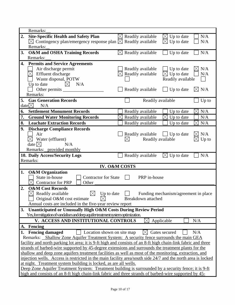
Remarks: 2. Site-Specific Health and Safety Plan Readily available Up to date N/A
Contingency plan/emergency response plan Readily available Up to date N/A Remarks:
3. O&M and OSHA Training Records Readily available Up to date N/A Remarks: 4. Permits and Service Agreements
Air discharge permit Readily available Up to date N/A Effluent discharge Readily available Up to date N/A
Waste disposal, POTW Readily available Up to date N/A
Other permits Readily available Up to date N/A Remarks: 5. Gas Generation Records Readily available Up to date N/A 6. Settlement Monument Records Readily available Up to date N/A 7. Ground Water Monitoring Records Readily available Up to date N/A 8. Leachate Extraction Records Readily available Up to date N/A 9. Discharge Compliance Records
Air Readily available Up to date N/A Water (effluent) Readily available Up to
date N/A Remarks: provided monthly 10. Daily Access/Security Logs Readily available Up to date N/A Remarks:
IV. O&M COSTS 1. O&M Organization
State in-house Contractor for State PRP in-house Contractor for PRP Other
2. O&M Cost Records Readily available Up to date Funding mechanism/agreement in place
Original O&M cost estimate Breakdown attached Annual costs are included in the five-year review report
3. Unanticipated or Unusually High O&M Costs During Review Period Yes, for mitigation of vandalism and deep aquifer treatment system optimization.
V. ACCESS AND INSTITUTIONAL CONTROLS Applicable N/A A. Fencing 1. Fencing damaged Location shown on site map Gates secured N/A Remarks: Shallow Zone Aquifer Treatment System: A security fence surrounds the main GEA facility and north parking lot area; it is 9-ft high and consists of an 8-ft high chain-link fabric and three strands of barbed-wire supported by 45-degree extensions and surrounds the treatment plants for the shallow and deep zone aquifers treatment facilities as well as most of the monitoring, extraction, and injection wells. Access is restricted in the main facility area/south side 24/7 and the north area is locked at night. Treatment system building is locked, as are all wells. Deep Zone Aquifer Treatment System: Treatment building is surrounded by a security fence; it is 9-ft high and consists of an 8-ft high chain-link fabric and three strands of barbed-wire supported by 45
Page 10 of 17

degree extensions. Access is controlled by the plant personnel. All wells are outside of the fenced area but they are secured, extraction wells at the deep zone aquifer being also equipped with alarm systems after vandalism affected system operation. Access at the deep zone aquifer controlled by the contractor, Axis B. Other Access Restrictions 1. Signs and other security measures Location shown on site map N/A
Remarks: . C. Institutional Controls
1. Implementation and enforcement Site conditions imply institutional controls not properly implemented Yes No N/A Site conditions imply institutional controls not being fully enforced Yes No N/A Type of monitoring (e.g., self-reporting, drive by) Reporting by other entities to EPA; New Mexico Office of the State Engineers (NMOSE) drilling restrictions; ground water discharge permit Frequency: monthly reporting of discharged volumes, quarterly sampling for groundwater permit Responsible party/agency GEA; EPA; NMED Contact NA
Name Title Date Phone no. Reporting is up-to-date Yes No N/A Reports are verified by the lead agency Yes No N/A Specific requirements in deed or decision documents have been met Yes No N/A Violations have been reported Yes No N/A Other problems or suggestions: EPA region 6 receives periodic report from entities covered by the Unilateral Order. NMOSE restricts issuing permits for drilling vicinity of the Site. NMED issued permit for ground water discharges. 2. Adequacy Institutional controls are adequate Institutional controls are inadequate N/A
Remarks:
D. General 1. Vandalism/trespassing Location shown on site map No vandalism evident
Remarks: Past problems with vandalism that have been corrected and alarm system installed
2. Land use changes onsite N/A Remarks:
Page 11 of 17

3. Land use changes offsite N/A Remarks: The land use is predominantly industrial, which is unlikely to change in the future.
VI. GENERAL SITE CONDITIONS A. Roads Applicable N/A
Remarks: The roads were in reasonable condition. B. Other Site Conditions Applicable N/A
Remarks: The site’s general appearance was excellent and well maintained. VII. LANDFILL COVERS Applicable N/A
A. Landfill Surface 1. Settlement (Low spots) Location shown on site map Settlement not evident
Areal extent Depth
Remarks:
2. Cracks Location shown on site map Cracking not evident
Lengths Widths Depths
Remarks:
3. Erosion Location shown on site map Substantial erosion not evident
Areal extent Depth
Remarks:
4. Holes Holes evident Holes not evident
Page 12 of 17

Areal extent Depth
Remarks: 5. Vegetative Cover Grass Cover properly established No signs of stress
Trees/Shrubs (indicate size and locations on a diagram) (None) Remarks:
6. Alternative Cover (armored rock, concrete, etc.) N/A
Remarks: Surface water relief channels were noted with rip-rap and armored as necessary.
7. Bulges Location shown on site map Bulges not evident
Areal extent Depth
Remarks:
8. Wet Areas/Water Damage Wet areas/water damage not evident Wet areas Location shown on site map Areal extent
Ponding Location shown on site map Areal extent Seeps Location shown on site map Areal extent
Soft subgrade Location shown on site map Areal extent
Remarks:
9. Slope Instability Slides Location shown on site map
No evidence of slope instability Areal extent
Remarks:
B. Benches Applicable N/A
Page 13 of 17

(Horizontally constructed mounds of earth placed across a steep landfill side slope to interrupt the slope in order to slow down the velocity of surface runoff and intercept and convey the runoff to a lined channel.)
1. Flows Bypass Bench Location shown on site map N/A or okay
Remarks:
2. Bench Breached Location shown on site map N/A or okay
Remarks:
3. Bench Overtopped Location shown on site map N/A or okay
Remarks:
C. Letdown Channels Applicable N/A 1. Settlement Location shown on site map No evidence of settlement
Areal extent Depth
Remarks:
2. Material Degradation Location shown on site map No evidence of degradation
Material type Areal extent
Remarks:
3. Erosion Location shown on site map No evidence of erosion
Page 14 of 17

Areal extent Depth
Remarks:
4. Undercutting Location shown on site map No evidence of undercutting
Areal extent Depth
Remarks:
5. Obstructions Type
No obstructions Location shown on site map
Areal extent Size
Remarks:
6. Excessive Vegetative Growth Type
No evidence of excessive growth Vegetation in channels does not obstruct flow Location shown on site map Areal extent
Remarks: D. Cover Penetrations Applicable N/A 1. Gas Vents
Properly secured/locked Active
Functioning Passive Routinely sampled Good condition
Page 15 of 17

Evidence of leakage at penetration Needs O&M N/A Remarks:
2. Gas Monitoring Probes Properly secured/locked Functioning Routinely sampled Good condition
Evidence of leakage at penetration Needs O&M N/A
Remarks:
3. Monitoring Wells (within surface area of landfill) Evidence of leakage at penetration Needs O&M N/A
Remarks: 4. Leachate Extraction Wells
Properly secured/locked Functioning Routinely sampled Good condition Evidence of leakage at penetration Needs O&M N/A
Remarks:
5. Settlement Monuments Located Routinely surveyed N/A
Remarks:
E. Gas Collection and Treatment Applicable N/A 1. Gas Treatment Facilities
Flaring Thermal destruction Collection for reuse Good condition Needs O&M
Remarks:
2. Gas Collection Wells, Manifolds, and Piping Good condition Needs O&M
Remarks:
3. Gas Monitoring Facilities (e.g., gas monitoring of adjacent homes or buildings) Good condition Needs O&M N/A
Page 16 of 17

Remarks:
F. Cover Drainage Layer Applicable N/A 1. Outlet Pipes Inspected Functioning
Remarks:
N/A
2. Outlet Rock Inspected Functioning
Remarks:
N/A
G. Detention/Sedimentation Ponds Applicable N/A
1. Siltation Areal extent
N/A Siltation not evident Remarks:
Size
2. Erosion Areal extent
Erosion not evident
Remarks:
Depth
3. Outlet Works Functioning
Remarks:
N/A
4. Dam Functioning N/A
Page 17 of 17

Remarks:
H. Retaining Walls Applicable N/A 1. Deformations Location shown on site map Deformation not evident
Horizontal displacement Vertical displacement
Rotational displacement
Remarks:
2. Degradation Location shown on site map Degradation not evident
Remarks:
I. Perimeter Ditches/Off-Site Discharge Applicable N/A 1. Siltation Location shown on site map Siltation not evident
Areal extent Depth
Remarks:
2. Vegetative Growth Location shown on site map N/A Vegetation does not impede flow
Areal extent Type
Page 18 of 17

Remarks:
3. Erosion Location shown on site map
Areal extent Depth
Remarks:
Erosion not evident
4. Discharge Structure Functioning N/A
Remarks:
VIII. VERTICAL BARRIER WALLS Applicable N/A 1. Settlement Location shown on site map
Areal extent Depth
Remarks:
Settlement not evident
2. Performance Monitoring Type of monitoring
Performance not monitored Frequency Evidence of breaching
Page 19 of 17
Head differential
Remarks:
IX. GROUND WATER/SURFACE WATER REMEDIES Applicable N/A A. Ground water Extraction Wells, Pumps, and Pipelines Applicable N/A 1. Pumps, Wellhead Plumbing, and Electrical
Good condition All required wells located Needs O&M N/A Remarks:
2. Extraction System Pipelines, Valves, Valve Boxes, and Other Appurtenances Good condition Needs O&M
Remarks: 3. Spare Parts and Equipment
Readily available Good condition Requires upgrade Needs to be provided
Remarks:
B. Surface Water Collection Structures, Pumps, and Pipelines Applicable N/A 1. Collection Structures, Pumps, and Electrical
Good condition Needs O&M
Remarks:
2. Surface Water Collection System Pipelines, Valves, Valve Boxes, and Other Appurtenances Good condition Needs O&M
Remarks:
3. Spare Parts and Equipment Readily available Good condition Requires upgrade Needs to be provided
Remarks:
Page 20 of 17

C. Treatment System Applicable N/A 1. Treatment Train (Check components that apply)
Metals removal Oil/water separation Bioremediation Air stripping Carbon absorbers Filters
Additive (e.g., chelation agent, flocculent) AquaMag, pH control
Others
Good condition Needs O&M Sampling ports properly marked and functional Sampling/maintenance log displayed and up to date
Equipment properly identified Quantity of ground water treated annually (see report)
Quantity of surface water treated annually
Remarks: See different components for the Shallow and Deep Zone Treatment Systems described in detail in the report
2. Electrical Enclosures and Panels (Properly rated and functional) N/A Good condition Needs O&M
Remarks:
3. Tanks, Vaults, Storage Vessels N/A Good condition Proper secondary containment Needs O&M
Remarks: 4. Discharge Structure and Appurtenances
N/A Good condition Needs O&M
Remarks:
Page 21 of 17

5. Treatment Building(s) N/A Good condition (esp. roof and doorways) Needs repair
Chemicals and equipment properly stored
Remarks:
6. Monitoring Wells (Pump-and-treatment remedy) Properly secured/locked Functioning Routinely sampled Good condition
All required wells located Needs O&M N/A Remarks: All the wells of the Shallow Zone Aquifer Treatment System were visited and the great majority at the Deep Zone Aquifer Treatment System were checked during the visits.
D. Monitored Natural Attenuation Applicable N/A 1. Monitoring Wells (Natural attenuation remedy)
Properly secured/locked Functioning Routinely sampled Good condition All required wells located Needs O&M N/A
Remarks:
X. OTHER REMEDIES If there are remedies applied at the site that are not covered above, attach an inspection sheet describing the physical nature and condition of any facility associated with the remedy. An example would be soil vapor extraction.
XI. OVERALL OBSERVATIONS A. Implementation of the Remedy
Remedy functioned as designed. B. Adequacy of O&M
Current O&M activities for wells are adequate; C. Early Indicators of Potential Remedy Failure
There are no early indicators of potential remedy failure. D. Opportunities for Optimization
See Five-Year Review report.
Page 22 of 17

INSPECTION TEAM ROSTER – UNIVAR, USA, INC.
Name Organization Title Michael Hebert U.S. EPA Region 6 Remedial Project Manager Allan Pasteris NMED Project Manager George Sylvester Univar Senior Project Manager Katy Brantingham ARCADIS Principal Scientist Cristina Radu EA Engineering, Science and
Technology, Inc, Project Manager
INSPECTION TEAM ROSTER – GENERAL ELECTIRC AVIATION.
Name Organization Title Michael Hebert U.S. EPA Region 6 Remedial Project Manager Allan Pasteris NMED Project Manager Dana Beaulieu GEA EHS Manager Julie Einerson GEA Environmental Specialist Chris Anderson GEA Plant Manager Oscar Lackey Axis (formerly of GEA) Remediation Manager John Billiard Axis Principal Kevin Burks Axis Associate Leonard Stockton Axis Engineer Cristina Radu EA Engineering, Science and
Technology, Inc, Project Manager
Page 23 of 17

ATTACHMENT 3
INTERVIEW RECORDS

SUPERFUND FIVE-YEAR REVIEW SITE SURVEY
Site Name: South Valley Superfund Site EPA ID No.: NMD980745558
Location: Albuquerque, Bernalillo County, New Mexico Date:
Contact Made By:
Name: Michael Hebert Title: Remedial Project Manager Organization: U.S. EPA
Telephone No.: (214) 665-8315 E-Mail: [email protected]
Street Address: 1455 Ross Avenue, Suite 1200 City, State, Zip: Dallas, Texas 75202
Name: April Ballweg Title: Project Manager Organization: EA Engineering, Science, and Technology, Inc.
Telephone No.: (972) 459-5019 E-Mail: [email protected]
Street Address: 405 S. Highway 121, Building C, Suite 100 City, State, Zip: Lewisville, Texas 75067
Individual Contacted:
Name: Title: Organization:
Telephone No.: 505 247-3919 E-Mail: [email protected]
Street Address: City, State, Zip:
Survey Questions
Should you choose to respond, please return your survey form to April Ballweg at
EA Engineering, Science, and Technology, Inc. via email or postal service by 4 December 2009.
1. What is your general impression of the work conducted at the site since the last Five-Year Review period (since September 2005)?
2. What effect have site operations had on the surrounding community since the last Five-Year Review?
3. In the past five years, are you aware of any community concerns regarding the site or its operation and administration? If so, please provide details.
Page 1 of 3
12-16-2009
John W. Billiard, PE
The Shallow and Deep Groundwater Remediation Systems continue to be effective in remediating historic groundwater impacts. From June 2005 to November 2009, the Shallow Zone and Deep Zone Groundwater Treatment Systems have extracted, treated, and injected 156,100 gallons and 1.7 billion gallons of water, respectively. All water treated met all regulatory standards for this Site. These systems continue to contain historic impacts and are protective of human health and the environment.
The community has benefitted from the groundwater cleanup activities. Based on groundwater data, concentrations of contaminants have been eliminated in the groundwater beneath the residential neighborhood, north of the former North Plant 83 area. From startup to present, Shallow Zone Aquifer plumes have been reduced by more than 90% or eliminated altogether and Deep Zone Aquifer plumes have been reduced more than 50%.
No community concerns related to the Shallow Zone or Deep Zone Groundwater Remediation Systems have been expressed to Axis Group personnel or to GE.
Program Manager - Remediation Axis Group Inc.
PO 27656Albuquerque, NM 87125

SUPERFUND FIVE-YEAR REVIEW SITE SURVEY (continued)
Site Name: South Valley Superfund Site EPA ID No.: NMD980745558
Location: Albuquerque, Bernalillo County, New Mexico Date:
Survey Questions (Continued)
4. Are you aware of any events, incidents, or activities at the site in the past five years such as vandalism, trespassing, or emergency responses from local authorities? If so, please provide details.
5. Do you feel well informed about the site’s activities and progress? If not, please indicate how you would like to be informed about site activities – for example by e-mail, regular mail, fact sheets, meetings, etc.
6. Do you have any comments, suggestions, or recommendations regarding the site’s management or operation?
Page 2 of 3
12-16-2009
There have been incidents of vandalism to the Site facilities that included graffiti and the fence at the Deep Zone Groundwater Treatment Plant was cut. On two separate occasions, thieves stole copper wire from the Deep Zone Groundwater Treatment Plant. On behalf of GE, additional security steps have been taken to address these issues.
Axis Group manages the Site work for GE. Accordingly, we are very well informed of the Site's activities and progress.
On behalf of GE, Axis Group recommends continued operation of the Site systems, as appropriate. Over the last 5 years with EPA and NMED approvals, GE has optimized both the Shallow Zone and Deep Zone Groundwater Remediation Systems. In addition, GE expanded the monitoring well network at the Deep Zone Groundwater Remediation System. Based on groundwater data, it appears that the North Shallow Zone Groundwater Remediation System can be closed and the wells abandoned. The South Shallow Zone Groundwater Remediation System may require additional work prior to closure. Given the success to date in reducing and/or eliminating impacts to the groundwater and the effective treatment of extracted water, we anticipate a successful remediation in the foreseeable future in both the Shallow Zone and Deep Zone Aquifers.

Page 3 of 3

SUPERFUND FIVE-YEAR REVIEW SITE SURVEY
Site Name: South Valley Superfund Site EPA ID No.: NMD980745558
Location: Albuquerque, Bernalillo County, New Mexico Date: 1/6/10
Contact Made By:
Name: Michael Hebert Title: Remedial Project Manager Organization: U.S. EPA
Telephone No.: (214) 665-8315 E-Mail: [email protected]
Street Address: 1455 Ross Avenue, Suite 1200 City, State, Zip: Dallas, Texas 75202
Name: April Ballweg Title: Project Manager Organization: EA Engineering, Science, and Technology, Inc.
Telephone No.: (972) 459-5019 E-Mail: [email protected]
Street Address: 405 S. Highway 121, Building C, Suite 100 City, State, Zip: Lewisville, Texas 75067
Individual Contacted:
Name: George Sylvester Title: Project Manager Organization: Univar
Telephone No.:303.838.7260 E-Mail Address: [email protected]
Street Address: 32131 Steven Way City, State, Zip: Conifer, CO 80433
Survey Questions
Should you choose to respond, please return your survey form to April Ballweg at EA Engineering, Science, and Technology, Inc. via email or postal service by 4 December 2009.
1. What is your general impression of the work conducted at the site since the last Five-Year Review period (since September 2005)?
Final remediation of groundwater to below cleanup standards and quarterly monitoring to verify no rebound of concentrations.
2. What effect have site operations had on the surrounding community since the last Five-Year Review? NONE.
3. In the past five years, are you aware of any community concerns regarding the site or its operation and administration? If so, please provide details.
NONE
Page 1 of 2
SUPERFUND FIVE-YEAR REVIEW SITE SURVEY (continued)
Site Name: South Valley Superfund Site EPA ID No.: NMD980745558
Location: Albuquerque, Bernalillo County, New Mexico Date: 1/6/10
Survey Questions (Continued)
4. Are you aware of any events, incidents, or activities at the site in the past five years such as vandalism, trespassing, or emergency responses from local authorities? If so, please provide details.
NONE
5. Do you feel well informed about the site’s activities and progress? If not, please indicate how you would like to be informed about site activities – for example by e-mail, regular mail, fact sheets, meetings, etc.
NOT APPLICABLE
6. Do you have any comments, suggestions, or recommendations regarding the site’s management or operation?
NOT APPLICABLE
Page 2 of 2

SUPERFUND FIVE-YEAR REVIEW SITE SURVEY
Site Name: South Valley Superfund Site EPA ID No.: NMD980745558
Location: Albuquerque, Bernalillo County, New Mexico Date: November 12, 2009
Contact Made By:
Name: Michael Hebert Title: Remedial Project Manager Organization: U.S. EPA
Telephone No.: (214) 665-8315 E-Mail: [email protected]
Street Address: 1455 Ross Avenue, Suite 1200 City, State, Zip: Dallas, Texas 75202
Name: April Ballweg Title: Project Manager Organization: EA Engineering, Science, and Technology, Inc.
Telephone No.: (972) 459-5019 E-Mail: [email protected]
Street Address: 405 S. Highway 121, Building C, Suite 100 City, State, Zip: Lewisville, Texas 75067
Individual Contacted:
Name: Sarah Dalton Title: Project Manager Organization: Chevron
Telephone No.: 713-432-2582 E-Mail Address: [email protected]
Street Address: 4800 Fournace Place, E534B City, State, Zip: Bellaire, TX 77401
Survey Questions
Should you choose to respond, please return your survey form to April Ballweg at EA Engineering, Science, and Technology, Inc. via email or postal service by 4 December 2009.
1. What is your general impression of the work conducted at the site since the last Five-Year Review period (since September 2005)?
No comment.
2. What effect have site operations had on the surrounding community since the last Five-Year Review?
No known effect.
3. In the past five years, are you aware of any community concerns regarding the site or its operation and administration? If so, please provide details.
Not aware of any community concerns.
Page 1 of 2

SUPERFUND FIVE-YEAR REVIEW SITE SURVEY (continued)
Site Name: South Valley Superfund Site EPA ID No.: NMD980745558
Location: Albuquerque, Bernalillo County, New Mexico Date: November 12, 2009
Survey Questions (Continued)
4. Are you aware of any events, incidents, or activities at the site in the past five years such as vandalism, trespassing, or emergency responses from local authorities? If so, please provide details.
No known concerns.
5. Do you feel well informed about the site’s activities and progress? If not, please indicate how you would like to be informed about site activities – for example by e-mail, regular mail, fact sheets, meetings, etc.
No. It would be useful to receive updates on site activities and progress via fact sheets, which could be submitted by either email or regular mail.
6. Do you have any comments, suggestions, or recommendations regarding the site’s management or operation?
No comments, suggestions, or recommendations.
Page 2 of 2

SUPERFUND FIVE-YEAR REVIEW SITE SURVEY
Site Name: South Valley Superfund Site EPA ID No.: NMD980745558
Location: Albuquerque, Bernalillo County, New Mexico Date: 12/17/09
Contact Made By: April Ballweg
Name: Michael Hebert Title: Remedial Project Manager Organization: U.S. EPA
Telephone No.: (214) 665-8315 E-Mail: [email protected]
Street Address: 1455 Ross Avenue, Suite 1200 City, State, Zip: Dallas, Texas 75202
Name: April Ballweg Title: Project Manager Organization: EA Engineering, Science, and Technology, Inc.
Telephone No.: (972) 459-5019 E-Mail: [email protected]
Street Address: 405 S. Highway 121, Building C, Suite 100 City, State, Zip: Lewisville, Texas 75067
Individual Contacted:
Name:Allan Pasteris Title: State Project Manager Organization:NMED
Telephone No.:(505) 827-0039 E-Mail Address:[email protected]
Street Address:1190 St. Francis Dr. City, State, Zip:Santa Fe, NM 87502
Survey Questions
Should you choose to respond, please return your survey form to April Ballweg at EA Engineering, Science, and Technology, Inc. via email or postal service by 18 December 2009.
1. What is your general impression of the work conducted at the site since the last Five-Year Review period (since September 2005)?
Both operable units (GE and Univar) continue to be in compliance with the Record of Decision.
2. What effect have site operations had on the surrounding community since the last Five-Year Review?
I have not been made aware of any adverse effects the remedial operations may have had on the surrounding community since the last Five-Year Review.
3. In the past five years, are you aware of any community concerns regarding the site or its operation and administration? If so, please provide details.
This year (2009) when GE announced the planned closure of their Aviation operations in the South Valley. The community and the City of Albuquerque expressed concerns about how the closure would impact the remedial operations at the site. It also prompted additional questions about progress at the site.
Page 1 of 3

SUPERFUND FIVE-YEAR REVIEW SITE SURVEY (continued)
Site Name: South Valley Superfund Site EPA ID No.: NMD980745558
Location: Albuquerque, Bernalillo County, New Mexico Date: 12/17/09
Survey Questions (Continued)
4. Are you aware of any events, incidents, or activities at the site in the past five years such as vandalism, trespassing, or emergency responses from local authorities? If so, please provide details.
NMED was advised of one instance of vandalism at the GE operable unit. Copper wiring was stolen from the GE remedial operations. This caused a temporary disruption to remedial activities. Repairs were quickly made. This was not an isolated incident at GE, other industrial facilities in the South Valley were also victimized. GE did address security and access to their facilities. No further thefts that disrupted remedial operations were reported.
NMED responded to GE’s request for assistance in February 2008 when waste oil was discovered in a sump and surrounding soil within the GE plant. NMED provided oversight of GE’s clean-up efforts. Sampling results for VOCs, SVOCs, PCBs and metals were non-detect or below regulatory action levels.
5. Do you feel well informed about the site’s activities and progress? If not, please indicate how you would like to be informed about site activities – for example by e-mail, regular mail, fact sheets, meetings, etc.
As the State Project Manager for the South Valley Superfund Site I feel well informed as to the site activities and progress.
6. Do you have any comments, suggestions, or recommendations regarding the site’s management or operation?
GE should consider some alternative technology to assist with the remediation of the two remaining areas of COCs above ARARs.
Univar should evaluate the occurrence of 1,4-Dioxane at the Edmund Street Ground Water Operable Unit and to provide recommended actions to ensure that does not present a threat to human health and the environment.
Page 2 of 3

Page 3 of 3

SUPERFUND FIVE-YEAR REVIEW SITE SURVEY
Site Name: South Valley Superfund Site EPA ID No.: NMD980745558
Location: Albuquerque, Bernalillo County, New Mexico Date:
Contact Made By:
Name: Michael Hebert Title: Remedial Project Manager Organization: U.S. EPA
Telephone No.: (214) 665-8315 E-Mail: [email protected]
Street Address: 1455 Ross Avenue, Suite 1200 City, State, Zip: Dallas, Texas 75202
Name: April Ballweg Title: Project Manager Organization: EA Engineering, Science, and Technology, Inc.
Telephone No.: (972) 459-5019 E-Mail: [email protected]
Street Address: 405 S. Highway 121, Building C, Suite 100 City, State, Zip: Lewisville, Texas 75067
Individual Contacted:
Name: George Schroeder Title: Env. Health Mgr. Organization: Bernalillo Cty.
Telephone No.: 505 314-0326 E-Mail: [email protected]
Street Address: 111 Union Square St SE City, State, Zip: Albuquerque, NM 87102
Survey Questions
Should you choose to respond, please return your survey form to April Ballweg at
EA Engineering, Science, and Technology, Inc. via email or postal service by 4 December 2009.
1. What is your general impression of the work conducted at the site since the last Five-Year Review period (since September 2005)?
Not much appears to have happened.
2. What effect have site operations had on the surrounding community since the last Five-Year Review?
Residents are concerned that volatiles from the groundwater are becoming airborne.
3. In the past five years, are you aware of any community concerns regarding the site or its operation and administration? If so, please provide details.
Described in #2, above.
Page 1 of 3

SUPERFUND FIVE-YEAR REVIEW SITE SURVEY (continued)
Site Name: South Valley Superfund Site EPA ID No.: NMD980745558
Location: Albuquerque, Bernalillo County, New Mexico Date:
Survey Questions (Continued)
4. Are you aware of any events, incidents, or activities at the site in the past five years such as vandalism, trespassing, or emergency responses from local authorities? If so, please provide details.
Not aware of any.
5. Do you feel well informed about the site’s activities and progress? If not, please indicate how you would like to be informed about site activities – for example by e-mail, regular mail, fact sheets, meetings, etc.
I do not remember receiving fact sheets on this site. Regular mail, fact sheets, would be useful.
6. Do you have any comments, suggestions, or recommendations regarding the site’s management or operation?
Just to explain the methods being used to remediate the site and what the timeframe is for completion…and how frequently monitoring is occurring.
Page 2 of 3

Page 3 of 3

Page Intentionally Left Blank

ATTACHMENT 4
SITE INSPECTION PHOTOGRAPHS

Site Inspection Photographs - Univar South Valley Superfund Site Fourth Five-Year Review
Photograph No. 1 Site: South Valley Superfund Site Description: View of SV-10 area Date: January 21, 2010 Direction: Southeast
Photograph No. 2 Site: South Valley Superfund Site Description: Monitoring wells GM-07 (right) and GM-08 (left) Date: January 21, 2010 Direction: NA
Page 1 of 40

Site Inspection Photographs - Univar South Valley Superfund Site Fourth Five-Year Review
Photograph No. 3 Site: South Valley Superfund Site Description: Well GM-05; concrete patch over the connection to the extraction system Date: January 21, 2010 Direction: Northwest
Photograph No. 4 Site: South Valley Superfund Site Description: View of well GW-04 (foreground) and GM-3 (in the distance); site visit participants (from left to right): Allan Pasteris (New Mexico Environment Department), George Sylvester (Univar USA, Inc.), Katy Brantingham (ARCADIS ), and Michael Hebert (U.S. Environmental Protection Agency Region 6) Date: January 21, 2010 Direction: West
Page 2 of 40

Site Inspection Photographs - Univar South Valley Superfund Site Fourth Five-Year Review
Photograph No. 5 Site: South Valley Superfund Site Description: Wells GM-03, GM-04, and GM-19 (in the far distance) Date: January 21, 2010 Direction: West
Photograph No. 6 Site: South Valley Superfund Site Description: Deep well A-02 Date: January 21, 2010 Direction: West
Page 3 of 40

Site Inspection Photographs - Univar South Valley Superfund Site Fourth Five-Year Review
Photograph No. 7 Site: South Valley Superfund Site Description: View of infiltration gallery Date: January 21, 2010 Direction: North
Page 4 of 40

Site Inspection Photographs - Univar South Valley Superfund Site Fourth Five-Year Review
Photograph No. 8 Site: South Valley Superfund Site Description: Air stripper building Date: January 21, 2010 Direction: NA
Page 5 of 40

Site Inspection Photographs - Univar South Valley Superfund Site Fourth Five-Year Review
Photograph No. 9 Site: South Valley Superfund Site Description: View of the recovery lines inside of the stripper building; each well connected to a separate line Date: January 21, 2010 Direction: NA
Photograph No. 10 Site: South Valley Superfund Site Description: View of the treatment unit Date: January 21, 2010 Direction: NA
Page 6 of 40

Site Inspection Photographs - Univar South Valley Superfund Site Fourth Five-Year Review
Photograph No. 11 Site: South Valley Superfund Site Description: Influent sampling port Date: January 21, 2010 Direction: NA
Photograph No. 12 Site: South Valley Superfund Site Description: Effluent sampling port Date: January 21, 2010 Direction: NA
Page 7 of 40

Site Inspection Photographs - Univar South Valley Superfund Site Fourth Five-Year Review
Photograph No. 13 Site: South Valley Superfund Site Description: Individual line sampling ports Date: January 21, 2010 Direction: NA
Page 8 of 40

Site Inspection Photographs - Univar South Valley Superfund Site Fourth Five-Year Review
Photograph No. 14 Site: South Valley Superfund Site Description: View of the stripping tower at the treatment building Date: January 21, 2010 Direction: NA
Page 9 of 40

Site Inspection Photographs - Univar South Valley Superfund Site Fourth Five-Year Review
Photograph No. 15 Site: South Valley Superfund Site Description: View inside the telemetry building Date: January 21, 2010 Direction: NA
Page 10 of 40

Site Inspection Photographs - Univar South Valley Superfund Site Fourth Five-Year Review
Photograph No. 16 Site: South Valley Superfund Site Description: Controller unit inside the telemetry building Date: January 21, 2010 Direction: NA
Page 11 of 40

Site Inspection Photographs - Univar South Valley Superfund Site Fourth Five-Year Review
Photograph No. 17 Site: South Valley Superfund Site Description: Spare parts inside the telemetry unit Date: January 21, 2010 Direction: NA
Photograph No. 18 Site: South Valley Superfund Site Description: Overall view of the treatment (to the right) and telemetry (to the left) buildings Date: January 21, 2010 Direction: West
Page 12 of 40
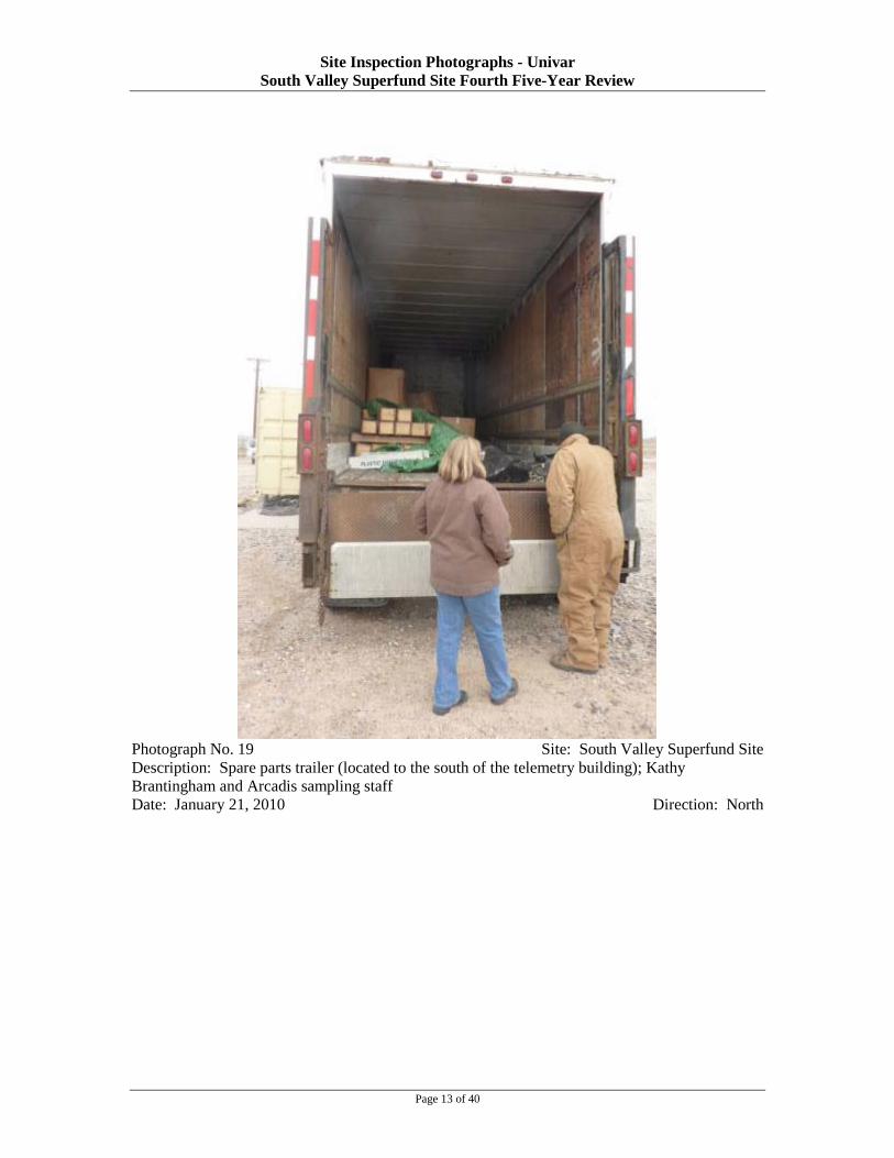
Site Inspection Photographs - Univar South Valley Superfund Site Fourth Five-Year Review
Photograph No. 19 Site: South Valley Superfund Site Description: Spare parts trailer (located to the south of the telemetry building); Kathy Brantingham and Arcadis sampling staff Date: January 21, 2010 Direction: North
Page 13 of 40

Site Inspection Photographs - Univar South Valley Superfund Site Fourth Five-Year Review
Photograph No. 20 Site: South Valley Superfund Site Description: Detail view inside the trailer Date: January 21, 2010 Direction: NA
Photograph No. 21 Site: South Valley Superfund Site Description: Arcadis sampling trailer at wells GM-17S and GM-17D Date: January 21, 2010 Direction: Northwest
Page 14 of 40

Site Inspection Photographs - Univar South Valley Superfund Site Fourth Five-Year Review
Photograph No. 22 Site: South Valley Superfund Site Description: Wells GM-17S (left) and GM-17D (right) Date: January 21, 2010 Direction: Northwest
Photograph No. 23 Site: South Valley Superfund Site Description: View of wells GM-24S (left) and GM-24D (right) from GM-17 cluster Date: January 21, 2010 Direction: Northeast
Page 15 of 40

Site Inspection Photographs - Univar South Valley Superfund Site Fourth Five-Year Review
Photograph No. 24 Site: South Valley Superfund Site Description: Close-up of GM-24S (left) and GM-24D (right) Date: January 21, 2010 Direction: Northeast
Photograph No. 25 Site: South Valley Superfund Site Description: View of sampling at GM-17S Date: January 21, 2010 Direction: NA
Page 16 of 40

Site Inspection Photographs - Univar South Valley Superfund Site Fourth Five-Year Review
Photograph No. 26 Site: South Valley Superfund Site Description: View of the sampling trailer Date: January 21, 2010 Direction: NA
Photograph No. 27 Site: South Valley Superfund Site Description: View of the sampling trailer Date: January 21, 2010 Direction: NA
Page 17 of 40

Site Inspection Photographs - Univar South Valley Superfund Site Fourth Five-Year Review
Photograph No. 28 Site: South Valley Superfund Site Description: View of the sampling trailer – measurement of water quality parameters Date: January 21, 2010 Direction: NA
Page 18 of 40

Site Inspection Photographs - Univar South Valley Superfund Site Fourth Five-Year Review
Photograph No. 29 Site: South Valley Superfund Site Description: View of the treatment unit Date: January 21, 2010 Direction: South
Page 19 of 40

Site Inspection Photographs - Univar South Valley Superfund Site Fourth Five-Year Review
Photograph No. 30 Site: South Valley Superfund Site Description: Pavement scars at former location of GM-16 Date: January 21, 2010 Direction: Northeast
Photograph No. 31 Site: South Valley Superfund Site Description: Pads associated with former AmeriGas buildings Date: January 21, 2010 Direction: NA
Page 20 of 40

Site Inspection Photographs - Univar South Valley Superfund Site Fourth Five-Year Review
Photograph No. 32 Site: South Valley Superfund Site Description: View of wells A-01 (forefront) and GM-06 Date: January 21, 2010 Direction: South
Page 21 of 40

Site Inspection Photographs - Univar South Valley Superfund Site Fourth Five-Year Review
Photograph No. 33 Site: South Valley Superfund Site Description: View of extraction well VE-04 Date: January 21, 2010 Direction: Southeast
Photograph No. 34 Site: South Valley Superfund Site Description: Southwest corner of the Univar facility; view of monitoring well GM-09 and recovery well RW0-01 Date: January 21, 2010 Direction: Southeast
Page 22 of 40

Site Inspection Photographs - Univar South Valley Superfund Site Fourth Five-Year Review
Photograph No. 35 Site: South Valley Superfund Site Description: Recovery well RW-01 Date: January 21, 2010 Direction: NA
Page 23 of 40

Site Inspection Photographs - Univar South Valley Superfund Site Fourth Five-Year Review
Photograph No. 36 Site: South Valley Superfund Site Description: View of the vapor extraction system Date: January 21, 2010 Direction: NA
Page 24 of 40

Site Inspection Photographs - Univar South Valley Superfund Site Fourth Five-Year Review
Photograph No. 37 Site: South Valley Superfund Site Description: View of the vapor extraction system Date: January 21, 2010 Direction: NA
Photograph No. 38 Site: South Valley Superfund Site Description: View of the GM-09 and RW-01 area from the vapor extraction system platform Date: January 21, 2010 Direction: NA
Page 25 of 40

Site Inspection Photographs - Univar South Valley Superfund Site Fourth Five-Year Review
Photograph No. 39 Site: South Valley Superfund Site Description: Overall view of GM-09, RW-01, and vapor extraction system Date: January 21, 2010 Direction: South
Page 26 of 40

Site Inspection Photographs - Univar South Valley Superfund Site Fourth Five-Year Review
Photograph No. 40 Site: South Valley Superfund Site Description: View of GM-02 Date: January 21, 2010 Direction: East
Page 27 of 40

Site Inspection Photographs - Univar South Valley Superfund Site Fourth Five-Year Review
Photograph No. 41 Site: South Valley Superfund Site Description: View of well GM-01 by entry gate to the Univar facility Date: January 21, 2010 Direction: North
Photograph No. 42 Site: South Valley Superfund Site Description: Outside of the gate of the Univar facility Date: January 21, 2010 Direction: South
Page 28 of 40

Site Inspection Photographs - Univar South Valley Superfund Site Fourth Five-Year Review
Photograph No. 43 Site: South Valley Superfund Site Description: Outside of the gate of the Univar facility Date: January 21, 2010 Direction: North
Page 29 of 40

Site Inspection Photographs - Univar South Valley Superfund Site Fourth Five-Year Review
Photograph No. 44 Site: South Valley Superfund Site Description: Well I-01 Date: January 21, 2010 Direction: NA
Page 30 of 40

Site Inspection Photographs - Univar South Valley Superfund Site Fourth Five-Year Review
Photograph No. 45 Site: South Valley Superfund Site Description: Well I-01 and eastern cluster, including recovery well RW-02 in the background (Note one of the General Electric wells, P83-31D2, is visible to the right – flush mount.) Date: January 21, 2010 Direction: South
Page 31 of 40

Site Inspection Photographs - Univar South Valley Superfund Site Fourth Five-Year Review
Photograph No. 46 Site: South Valley Superfund Site Description: View of eastern cluster Date: January 21, 2010 Direction: South
Page 32 of 40

Site Inspection Photographs - Univar South Valley Superfund Site Fourth Five-Year Review
Photograph No. 47 Site: South Valley Superfund Site Description: View of RW-03 and Interstate-25 Date: January 21, 2010 Direction: Southeast
Page 33 of 40

Site Inspection Photographs - Univar South Valley Superfund Site Fourth Five-Year Review
Photograph No. 48 Site: South Valley Superfund Site Description: View of the vault containing piping leading to RW-04, located east of Interstate-25 Date: January 21, 2010 Direction: East
Photograph No. 49 Site: South Valley Superfund Site Description: Junction box by recovery well RW-02 Date: January 21, 2010 Direction: West
Page 34 of 40

Site Inspection Photographs - Univar South Valley Superfund Site Fourth Five-Year Review
Photograph No. 50 Site: South Valley Superfund Site Description: Recovery well RW-03 Date: January 21, 2010 Direction: NA
Photograph No. 51 Site: South Valley Superfund Site Description: Well GM-21 by “Rubber Tree” road Date: January 21, 2010 Direction: South
Page 35 of 40

Site Inspection Photographs - Univar South Valley Superfund Site Fourth Five-Year Review
Photograph No. 52 Site: South Valley Superfund Site Description: Well GM-25, the southernmost well on the west side of Interstate-25 Date: January 21, 2010 Direction: South
Page 36 of 40
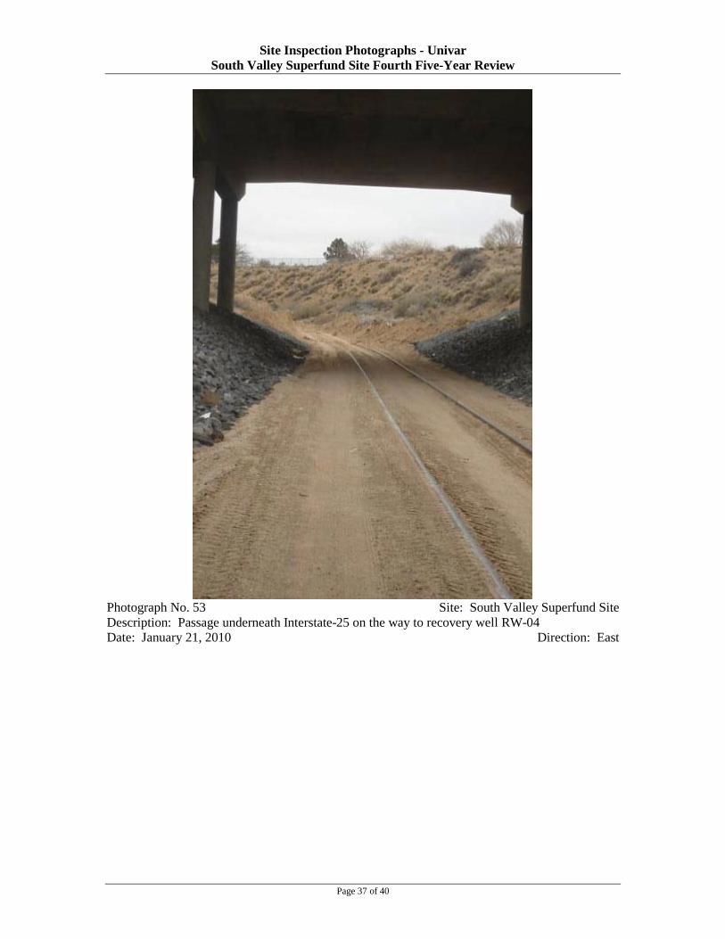
Site Inspection Photographs - Univar South Valley Superfund Site Fourth Five-Year Review
Photograph No. 53 Site: South Valley Superfund Site Description: Passage underneath Interstate-25 on the way to recovery well RW-04 Date: January 21, 2010 Direction: East
Page 37 of 40

Site Inspection Photographs - Univar South Valley Superfund Site Fourth Five-Year Review
Photograph No. 54 Site: South Valley Superfund Site Description: View of Univar facility from the east side of Interstate-25 Date: January 21, 2010 Direction: West
Photograph No. 55 Site: South Valley Superfund Site Description: View of recovery well RW-04 and GM-14 cluster Date: January 21, 2010 Direction: West
Page 38 of 40

Site Inspection Photographs - Univar South Valley Superfund Site Fourth Five-Year Review
Photograph No. 56 Site: South Valley Superfund Site Description: View of GM-15 cluster Date: January 21, 2010 Direction: North
Page 39 of 40

Site Inspection Photographs - Univar South Valley Superfund Site Fourth Five-Year Review
Photograph No. 57 Site: South Valley Superfund Site Description: Junction box Date: January 21, 2010 Direction: West
Page 40 of 40

Site Inspection Photographs – General Electric Aviation South Valley Superfund Site Fourth Five-Year Review
Photograph No. 1 Site: South Valley Superfund Site Description: Shallow Zone (SZ aquifer) Aquifer extraction well SEW-10 Date: January 27, 2010 Direction: NA
Photograph No. 2 Site: South Valley Superfund Site Description: SZ aquifer water level and water quality monitoring well SW-08 Date: January 27, 2010 Direction: NA
Page 1 of 56

Site Inspection Photographs – General Electric Aviation South Valley Superfund Site Fourth Five-Year Review
Photograph No. 3 Site: South Valley Superfund Site Description: SZ aquifer water level monitoring wells SW-04 (right) and SW-02 (left) Date: January 27, 2010 Direction: South
Photograph No. 4 Site: South Valley Superfund Site Description: SZ aquifer water level monitoring well S-04 Date: January 27, 2010 Direction: Southeast
Page 2 of 56

Site Inspection Photographs – General Electric Aviation South Valley Superfund Site Fourth Five-Year Review
Photograph No. 5 Site: South Valley Superfund Site Description: DZ aquifer well DWA-02 Date: January 27, 2010 Direction: NA
Photograph No. 6 Site: South Valley Superfund Site Description: SZ aquifer water level monitoring well SMW-17 Date: January 27, 2010 Direction: North
Page 3 of 56

Site Inspection Photographs – General Electric Aviation South Valley Superfund Site Fourth Five-Year Review
Photograph No. 7 Site: South Valley Superfund Site Description: SZ aquifer water level well monitoring SW-03 Date: January 27, 2010 Direction: Southwest
Page 4 of 56

Site Inspection Photographs – General Electric Aviation South Valley Superfund Site Fourth Five-Year Review
Photograph No. 8 Site: South Valley Superfund Site Description: SZ aquifer water level well monitoring SMW-16 Date: January 27, 2010 Direction: NA
Photograph No. 9 Site: South Valley Superfund Site Description: DZ aquifer water level and water quality monitoring well SMW-02 Date: January 27, 2010 Direction: NA
Page 5 of 56

Site Inspection Photographs – General Electric Aviation South Valley Superfund Site Fourth Five-Year Review
Photograph No. 10 Site: South Valley Superfund Site Description: SZ aquifer water level monitoring well SMW-19 Date: January 27, 2010 Direction: NA
Photograph No. 11 Site: South Valley Superfund Site Description: DZ aquifer water monitoring well DWA-02 Date: January 27, 2010 Direction: NA
Page 6 of 56

Site Inspection Photographs – General Electric Aviation South Valley Superfund Site Fourth Five-Year Review
Photograph No. 12 Site: South Valley Superfund Site Description: DZ aquifer water level and water quality monitoring well WB-07 Date: January 27, 2010 Direction: East
Page 7 of 56

Site Inspection Photographs – General Electric Aviation South Valley Superfund Site Fourth Five-Year Review
Photograph No. 13 Site: South Valley Superfund Site Description: DZ aquifer water level and water quality monitoring well WB-07 – close-up Date: January 27, 2010 Direction: East
Page 8 of 56

Site Inspection Photographs – General Electric Aviation South Valley Superfund Site Fourth Five-Year Review
Photograph No. 14 Site: South Valley Superfund Site Description: SZ aquifer water level monitoring well P83-17S Date: January 27, 2010 Direction: NA
Photograph No. 15 Site: South Valley Superfund Site Description: SZ aquifer water level monitoring well P83-18S Date: January 27, 2010 Direction: NA
Page 9 of 56

Site Inspection Photographs – General Electric Aviation South Valley Superfund Site Fourth Five-Year Review
Photograph No. 16 Site: South Valley Superfund Site Description: View of the SZ aquifer treatment unit building Date: January 27, 2010 Direction: North
Photograph No. 17 Site: South Valley Superfund Site Description: SZ aquifer water level monitoring well SMW-09 Date: January 27, 2010 Direction: NA
Page 10 of 56

Site Inspection Photographs – General Electric Aviation South Valley Superfund Site Fourth Five-Year Review
Photograph No. 18 Site: South Valley Superfund Site Description: SZ aquifer extraction well SEW-05 Date: January 27, 2010 Direction: NA
Photograph No. 19 Site: South Valley Superfund Site Description: SZ aquifer water level and water quality monitoring well SMW-10 Date: January 27, 2010 Direction: NA
Page 11 of 56

Site Inspection Photographs – General Electric Aviation South Valley Superfund Site Fourth Five-Year Review
Photograph No. 20 Site: South Valley Superfund Site Description: SZ aquifer water level monitoring well SMW-11 (Note some of the wells are unlocked, but they are located within a locked fenced area.) Date: January 27, 2010 Direction: NA
Page 12 of 56

Site Inspection Photographs – General Electric Aviation South Valley Superfund Site Fourth Five-Year Review
Photograph No. 21 Site: South Valley Superfund Site Description: DZ aquifer water level monitoring well DMW-03 Date: January 27, 2010 Direction: NA
Page 13 of 56

Site Inspection Photographs – General Electric Aviation South Valley Superfund Site Fourth Five-Year Review
Photograph No. 22 Site: South Valley Superfund Site Description: SZ aquifer extraction well SEW-03 Date: January 27, 2010 Direction: NA
Photograph No. 23 Site: South Valley Superfund Site Description: SZ aquifer water level monitoring well SMW-12 Date: January 27, 2010 Direction: NA
Page 14 of 56

Site Inspection Photographs – General Electric Aviation South Valley Superfund Site Fourth Five-Year Review
Photograph No. 24 Site: South Valley Superfund Site Description: SZ aquifer water level monitoring well SW-06 Date: January 27, 2010 Direction: NA
Photograph No. 25 Site: South Valley Superfund Site Description: DZ aquifer water level monitoring well IMW-06 Date: January 27, 2010 Direction: NA
Page 15 of 56

Site Inspection Photographs – General Electric Aviation South Valley Superfund Site Fourth Five-Year Review
Photograph No. 26 Site: South Valley Superfund Site Description: SZ aquifer extraction well SEW-04 Date: January 27, 2010 Direction: NA
Photograph No. 27 Site: South Valley Superfund Site Description: SZ aquifer treatment system – overall view Date: January 27, 2010 Direction: North
Page 16 of 56

Site Inspection Photographs – General Electric Aviation South Valley Superfund Site Fourth Five-Year Review
Photograph No. 28 Site: South Valley Superfund Site Description: SZ aquifer treatment system – leak detection and alarm control panels Date: January 27, 2010 Direction: NA
Photograph No. 29 Site: South Valley Superfund Site Description: SZ aquifer treatment system – extraction well control panels Date: January 27, 2010 Direction: NA
Page 17 of 56

Site Inspection Photographs – General Electric Aviation South Valley Superfund Site Fourth Five-Year Review
Photograph No. 30 Site: South Valley Superfund Site Description: SZ aquifer treatment system – effluent sampling port Date: January 27, 2010 Direction: NA
Photograph No. 31 Site: South Valley Superfund Site Description: SZ aquifer extraction well SEW-06 Date: January 27, 2010 Direction: NA
Page 18 of 56

Site Inspection Photographs – General Electric Aviation South Valley Superfund Site Fourth Five-Year Review
Photograph No. 32 Site: South Valley Superfund Site Description: SZ aquifer injection well SIW-01 Date: January 27, 2010 Direction: NA
Photograph No. 33 Site: South Valley Superfund Site Description: SZ aquifer water level and water quality monitoring well P83-01S Date: January 27, 2010 Direction: NA
Page 19 of 56
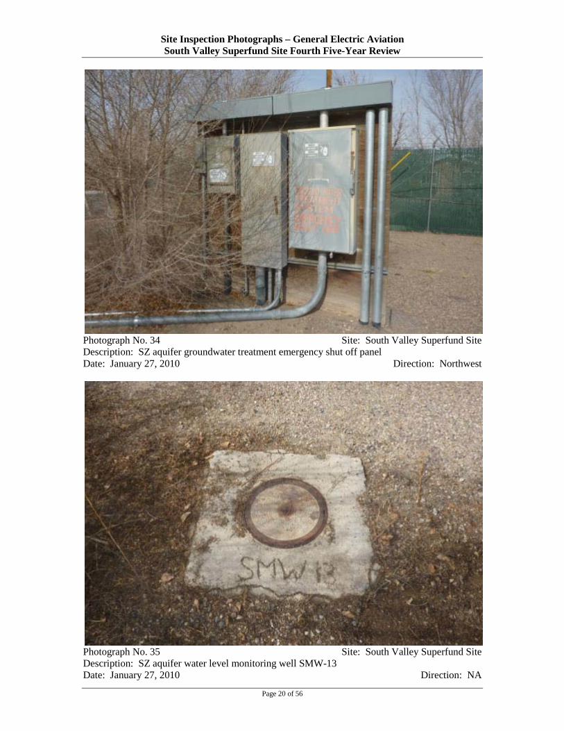
Site Inspection Photographs – General Electric Aviation South Valley Superfund Site Fourth Five-Year Review
Photograph No. 34 Site: South Valley Superfund Site Description: SZ aquifer groundwater treatment emergency shut off panel Date: January 27, 2010 Direction: Northwest
Photograph No. 35 Site: South Valley Superfund Site Description: SZ aquifer water level monitoring well SMW-13 Date: January 27, 2010 Direction: NA
Page 20 of 56

Site Inspection Photographs – General Electric Aviation South Valley Superfund Site Fourth Five-Year Review
Photograph No. 36 Site: South Valley Superfund Site Description: SZ aquifer water level monitoring well SMW-14 Date: January 27, 2010 Direction: NA
Photograph No. 37 Site: South Valley Superfund Site Description: SZ aquifer water level monitoring well SMW-18 Date: January 27, 2010 Direction: NA
Page 21 of 56

Site Inspection Photographs – General Electric Aviation South Valley Superfund Site Fourth Five-Year Review
Photograph No. 38 Site: South Valley Superfund Site Description: DZ aquifer treatment system control room – electrical panels Date: January 27, 2010 Direction: NA
Photograph No. 39 Site: South Valley Superfund Site Description: DZ aquifer treatment system control room – electrical panel detail Date: January 27, 2010 Direction: NA
Page 22 of 56

Site Inspection Photographs – General Electric Aviation South Valley Superfund Site Fourth Five-Year Review
Photograph No. 40 Site: South Valley Superfund Site Description: Influent piping and valves Date: January 27, 2010 Direction: NA
Page 23 of 56

Site Inspection Photographs – General Electric Aviation South Valley Superfund Site Fourth Five-Year Review
Photograph No. 41 Site: South Valley Superfund Site Description: AquaMag treatment system Date: January 27, 2010 Direction: NA
Page 24 of 56

Site Inspection Photographs – General Electric Aviation South Valley Superfund Site Fourth Five-Year Review
Photograph No. 42 Site: South Valley Superfund Site Description: Carbon dioxide tank, located along the eastern side of the treatment building Date: January 27, 2010 Direction: North
Page 25 of 56

Site Inspection Photographs – General Electric Aviation South Valley Superfund Site Fourth Five-Year Review
Photograph No. 43 Site: South Valley Superfund Site Description: Influent equalization tank TK-100 Date: January 27, 2010 Direction: NA
Page 26 of 56

Site Inspection Photographs – General Electric Aviation South Valley Superfund Site Fourth Five-Year Review
Photograph No. 44 Site: South Valley Superfund Site Description: Air strippers (Note: only one of the strippers is functioning after the optimization of the system.) Date: January 27, 2010 Direction: NA
Page 27 of 56

Site Inspection Photographs – General Electric Aviation South Valley Superfund Site Fourth Five-Year Review
Photograph No. 45 Site: South Valley Superfund Site Description: Blowers located along the northern side of the treatment building Date: January 27, 2010 Direction: Southwest
Photograph No. 46 Site: South Valley Superfund Site Description: Piping from influent water – spare piping located along the eastern fence of the treatment building Date: January 27, 2010 Direction: Northeast
Page 28 of 56

Site Inspection Photographs – General Electric Aviation South Valley Superfund Site Fourth Five-Year Review
Photograph No. 47 Site: South Valley Superfund Site Description: 10-micron filters Date: January 27, 2010 Direction: NA
Photograph No. 48 Site: South Valley Superfund Site Description: Carbon filters Date: January 27, 2010 Direction: NA
Page 29 of 56

Site Inspection Photographs – General Electric Aviation South Valley Superfund Site Fourth Five-Year Review
Photograph No. 49 Site: South Valley Superfund Site Description: Effluent surge tank TK-400 Date: January 27, 2010 Direction: NA
Page 30 of 56

Site Inspection Photographs – General Electric Aviation South Valley Superfund Site Fourth Five-Year Review
Photograph No. 50 Site: South Valley Superfund Site Description: 5-micron filters Date: January 27, 2010 Direction: NA
Photograph No. 51 Site: South Valley Superfund Site Description: Well sampling rig (Note purge water is containerized and brought to the plant to be treated.) Date: January 27, 2010 Direction: NA
Page 31 of 56

Site Inspection Photographs – General Electric Aviation South Valley Superfund Site Fourth Five-Year Review
Photograph No. 52 Site: South Valley Superfund Site Description: Carbon system wash tank (Note sediment is collected at the bottom and is removed by a vacuum truck.) Date: January 27, 2010 Direction: NA
Page 32 of 56

Site Inspection Photographs – General Electric Aviation South Valley Superfund Site Fourth Five-Year Review
Photograph No. 53 Site: South Valley Superfund Site Description: Pac-press – the filter press through which the effluent is put through before entering the treatment train Date: January 27, 2010 Direction: NA
Photograph No. 54 Site: South Valley Superfund Site Description: Air compressor which activates the control valves Date: January 27, 2010 Direction: NA
Page 33 of 56

Site Inspection Photographs – General Electric Aviation South Valley Superfund Site Fourth Five-Year Review
Photograph No. 55 Site: South Valley Superfund Site Description: Effluent sampling port SP-425 Date: January 27, 2010 Direction: NA
Photograph No. 56 Site: South Valley Superfund Site Description: Influent sampling ports Date: January 27, 2010 Direction: NA
Page 34 of 56

Site Inspection Photographs – General Electric Aviation South Valley Superfund Site Fourth Five-Year Review
Photograph No. 57 Site: South Valley Superfund Site Description: DZ aquifer injection well IW-638R Date: January 27, 2010 Direction: NA
Page 35 of 56

Site Inspection Photographs – General Electric Aviation South Valley Superfund Site Fourth Five-Year Review
Photograph No. 58 Site: South Valley Superfund Site Description: Detail inside the vault for DZ aquifer treatment system injection well IW-638R. Date: January 27, 2010 Direction: NA
Photograph No. 59 Site: South Valley Superfund Site Description: Detail of the security system installed on well vaults to prevent vandalism Date: January 27, 2010 Direction: NA
Page 36 of 56

Site Inspection Photographs – General Electric Aviation South Valley Superfund Site Fourth Five-Year Review
Photograph No. 60 Site: South Valley Superfund Site Description: DZ aquifer well nest P83-S and P-83-P (piezometers and monitoring well) Date: January 27, 2010 Direction: NA
Photograph No. 61 Site: South Valley Superfund Site Description: Vault cover with heavy concrete slab; installed to protect against vandalism Date: January 27, 2010 Direction: North
Page 37 of 56

Site Inspection Photographs – General Electric Aviation South Valley Superfund Site Fourth Five-Year Review
Photograph No. 62 Site: South Valley Superfund Site Description: Protective cover for vault of DZ aquifer extraction well EW-004 Date: January 27, 2010 Direction: NA
Photograph No. 63 Site: South Valley Superfund Site Description: Detail of DZ aquifer extraction well EW-004 Date: January 27, 2010 Direction: NA
Page 38 of 56

Site Inspection Photographs – General Electric Aviation South Valley Superfund Site Fourth Five-Year Review
Photograph No. 64 Site: South Valley Superfund Site Description: Rung stairs leading inside the vault of DZ aquifer extraction well EW-004 Date: January 27, 2010 Direction: NA
Photograph No. 65 Site: South Valley Superfund Site Description: DZ aquifer Westbay well WB-04 Date: January 27, 2010 Direction: NA
Page 39 of 56

Site Inspection Photographs – General Electric Aviation South Valley Superfund Site Fourth Five-Year Review
Photograph No. 66 Site: South Valley Superfund Site Description: DZ aquifer leak detection system – typical configuration Date: January 27, 2010 Direction: Northwest
Photograph No. 67 Site: South Valley Superfund Site Description: Leak detection system – detail Date: January 27, 2010 Direction: NA
Page 40 of 56
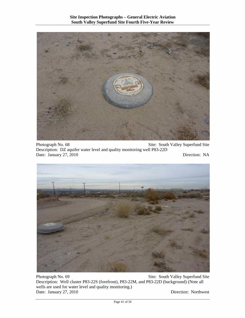
Site Inspection Photographs – General Electric Aviation South Valley Superfund Site Fourth Five-Year Review
Photograph No. 68 Site: South Valley Superfund Site Description: DZ aquifer water level and quality monitoring well P83-22D Date: January 27, 2010 Direction: NA
Photograph No. 69 Site: South Valley Superfund Site Description: Well cluster P83-22S (forefront), P83-22M, and P83-22D (background) (Note all wells are used for water level and quality monitoring.) Date: January 27, 2010 Direction: Northwest
Page 41 of 56

Site Inspection Photographs – General Electric Aviation South Valley Superfund Site Fourth Five-Year Review
Photograph No. 70 Site: South Valley Superfund Site Description: Water level and quality monitoring well P83-22M in foreground, electric vault with cover in the background Date: January 27, 2010 Direction: North
Page 42 of 56

Site Inspection Photographs – General Electric Aviation South Valley Superfund Site Fourth Five-Year Review
Photograph No. 71 Site: South Valley Superfund Site Description: SZ aquifer water level monitoring well P83-05S, located in front yard of residence on Bethel Avenue Southeast Date: February 2, 2010 Direction: North
Page 43 of 56

Site Inspection Photographs – General Electric Aviation South Valley Superfund Site Fourth Five-Year Review
Photograph No. 72 Site: South Valley Superfund Site Description: Detail of SZ aquifer water level monitoring well P83-05S Date: February 2, 2010 Direction: NA
Page 44 of 56

Site Inspection Photographs – General Electric Aviation South Valley Superfund Site Fourth Five-Year Review
Photograph No. 73 Site: South Valley Superfund Site Description: SZ aquifer water level monitoring well P83-16S, located in yard of residence on Bethel Avenue Southeast Date: February 2, 2010 Direction: NA
Photograph No. 74 Site: South Valley Superfund Site Description: View of residence on Bethel Avenue Southeast (Note well P83-16S is located in the yard, along the eastern fence, beyond the gate.) Date: February 2, 2010 Direction: North
Page 45 of 56
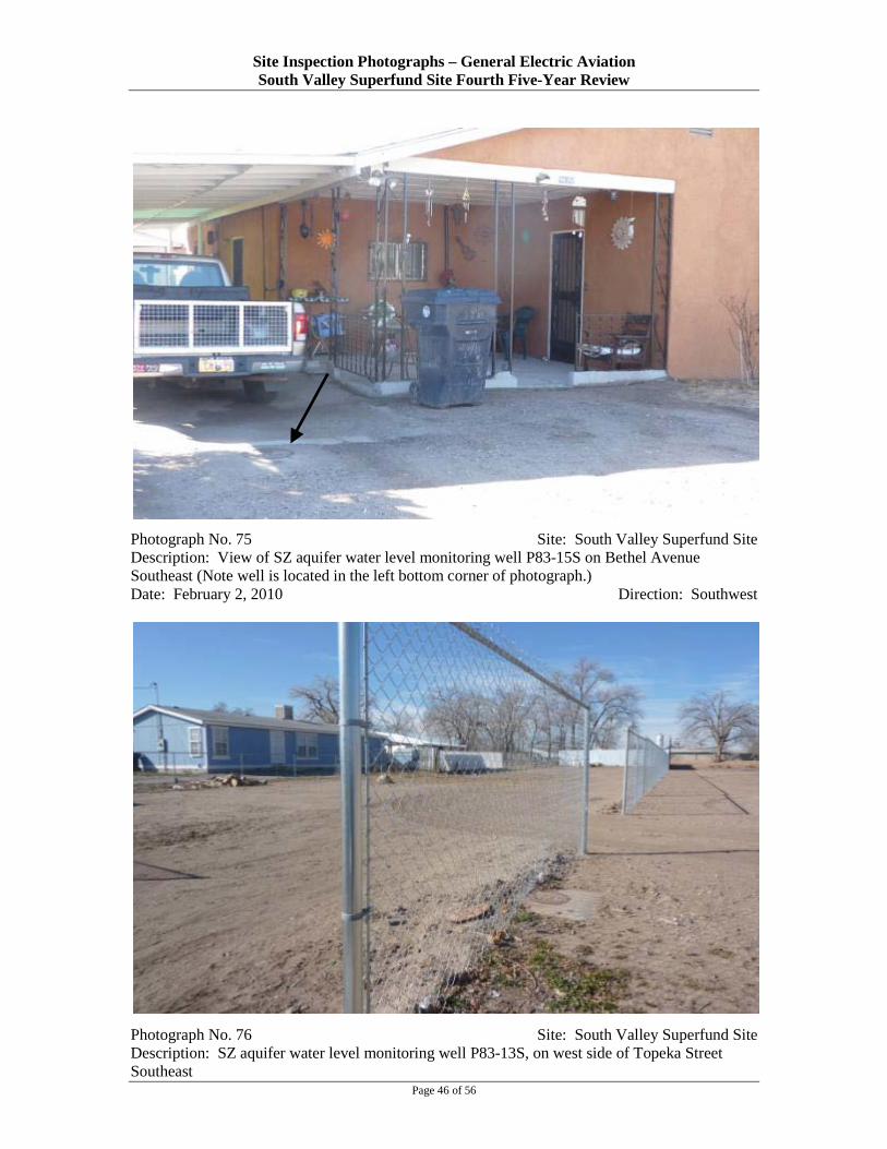
Site Inspection Photographs – General Electric Aviation South Valley Superfund Site Fourth Five-Year Review
Photograph No. 75 Site: South Valley Superfund Site Description: View of SZ aquifer water level monitoring well P83-15S on Bethel Avenue Southeast (Note well is located in the left bottom corner of photograph.) Date: February 2, 2010 Direction: Southwest
Photograph No. 76 Site: South Valley Superfund Site Description: SZ aquifer water level monitoring well P83-13S, on west side of Topeka Street Southeast
Page 46 of 56

Site Inspection Photographs – General Electric Aviation South Valley Superfund Site Fourth Five-Year Review
Date: February 2, 2010 Direction: West
Photograph No. 77 Site: South Valley Superfund Site Description: SZ aquifer water level monitoring well P83-12S Date: February 2, 2010 Direction: East
Photograph No. 78 Site: South Valley Superfund Site
Page 47 of 56

Site Inspection Photographs – General Electric Aviation South Valley Superfund Site Fourth Five-Year Review
Description: SZ aquifer water level monitoring well S-01, on south side of Descanso Road Southeast Date: February 2, 2010 Direction: South
Photograph No. 79 Site: South Valley Superfund Site Description: SZ aquifer water level monitoring well P83-04S, on north side of Descanso Road Southeast Date: February 2, 2010 Direction: North
Page 48 of 56

Site Inspection Photographs – General Electric Aviation South Valley Superfund Site Fourth Five-Year Review
Photograph No. 80 Site: South Valley Superfund Site Description: SZ aquifer water level monitoring well P83-02S, on north side of Descanso Road Southeast Date: February 2, 2010 Direction: North
Page 49 of 56

Site Inspection Photographs – General Electric Aviation South Valley Superfund Site Fourth Five-Year Review
Photograph No. 81 Site: South Valley Superfund Site Description: SZ aquifer extraction well SEW-2, on north side of Descanso Road Southeast Date: February 2, 2010 Direction: East
Page 50 of 56

Site Inspection Photographs – General Electric Aviation South Valley Superfund Site Fourth Five-Year Review
Photograph No. 82 Site: South Valley Superfund Site Description: View inside the vault for SZ aquifer extraction well SEW-2 Date: February 2, 2010 Direction: NA
Page 51 of 56

Site Inspection Photographs – General Electric Aviation South Valley Superfund Site Fourth Five-Year Review
Photograph No. 83 Site: South Valley Superfund Site Description: SZ aquifer water level monitoring well P83-14S, on north side of Abajo Road Southeast Date: February 2, 2010 Direction: NA
Page 52 of 56

Site Inspection Photographs – General Electric Aviation South Valley Superfund Site Fourth Five-Year Review
Photograph No. 84 Site: South Valley Superfund Site Description: SZ aquifer extraction well SEW-1, on north side of Abajo Road Southeast Date: February 2, 2010 Direction: East
Page 53 of 56

Site Inspection Photographs – General Electric Aviation South Valley Superfund Site Fourth Five-Year Review
Photograph No. 85 Site: South Valley Superfund Site Description: View inside the vault for extraction well SEW-1 Date: February 2, 2010 Direction: NA
Page 54 of 56

Site Inspection Photographs – General Electric Aviation South Valley Superfund Site Fourth Five-Year Review
Photograph No. 86 Site: South Valley Superfund Site Description: Extraction well SEW-11 (forefront) and water level and quality monitoring well P83-03S (background) Date: February 2, 2010 Direction: South
Page 55 of 56

Site Inspection Photographs – General Electric Aviation South Valley Superfund Site Fourth Five-Year Review
Photograph No. 87 Site: South Valley Superfund Site Description: View inside the vault of SZ aquifer extraction well SEW-11 Date: February 2, 2010 Direction: NA
Page 56 of 56