Four-Path Gas Ultrasonic Flow MeterGas Ultrasonic Flow Meter Datasheet Intelligence for Custody...
20
Datasheet August 2019 Daniel ™ SeniorSonic ™ 3414 Four-Path Gas Ultrasonic Flow Meter
Transcript of Four-Path Gas Ultrasonic Flow MeterGas Ultrasonic Flow Meter Datasheet Intelligence for Custody...

DatasheetAugust 2019
Daniel™ SeniorSonic™ 3414Four-Path Gas Ultrasonic Flow Meter


www.Emerson.com 1
DatasheetGas Ultrasonic Flow Meter
Intelligence for Custody TransferEngineered for custody transfer applications, the Daniel SeniorSonic 3414 Four-Path Gas Ultrasonic Flow Meter offers high accuracy and reliable, long-term performance to minimize lost and unaccounted for natural gas. The advanced meter is available in DN100 to DN1050 (4-in to 42-in)(1) line sizes and offers bi-directional flow capabilities, increased flow capacity and no incremental pressure drop to reduce measurement risk and minimize operating costs.
Powerful next-generation Daniel 3410 Series Electronics work with the SeniorSonic 3414 meter to significantly increase the sampling rate and provide high-volume data capture, including extensive hourly and daily logs. The streamlined electronics feature a plug-in ready, integrated CPU and I/O board assembly and a local LCD display (optional) to increase reliability, simplify maintenance and facilitate future expansion. Operators can also easily monitor and troubleshoot the meters in real time from a PC or laptop. Daniel MeterLink™ Diagnostics Software is an intuitive user interface that provides critical information, including expert flow analysis, flow disturbance alerts and suggested corrective actions, to enhance reliability and improve functionality.
The SeniorSonic 3414 meter is also supplied with robust titanium non-wetted T-200 Transducers that ensure reliable measurement in harsh environments where wet, rich and/or dirty gas is present. The transducers are engineered to simplify servicing and maximize meter uptime.
Typical Application � Custody transfer for natural gas transmission lines
Figure 1: Daniel SeniorSonic 3414 Gas Ultrasonic Flow Meter
(1) Consult factory on meter sizes above DN900 (36-in).
(2) Requires a Continuous Flow Analysis software key.
Application Sites � Power plants – inlets
� Gas processing plants – inlets/outlets
� Underground storage sites – inlets/outlets
Features and Benefits � Four-path chordal design allows accuracy, stability,
redundancy and operational cost savings
� Excellent long-term performance reduces maintenance costs
� High rangeability of >100:1 ensures fewer meter runs, smaller line sizes and lower capital costs
� Cast or forged body construction minimizes measurement uncertainty caused by pressure changes
� Equipped with robust titanium encapsulated T-200 Transducers for optimal performance in wet, sour and corrosive environments (standard for line sizes up to DN300 or 12")
� T-200 Transducers are safely extractable under pressure without special tools
� 3410 Series Electronics provide fast sampling, an expandable electronics platform and an archive data log containing pressure, temperature and gas composition information which allows the meter to calculate standard condition flow rates like a redundant flow computer
� 3410 Series Electronics calculate corrected volume rates, mass rates and energy rates
� 3410 Series Electronics calculate speed of sound from pressure, temperature, and gas compostion data (AGA 10 2008, AGA 8 Part 1 & 2 2017, GERG-2008)
� Local LCD display (optional) with up to nine user-selectable scrolling variables
� Daniel MeterLink Diagnostics Software allows access to expert flow analysis and provides an intuitive view of meter health; calibration cycles can be extended to minimize operating and maintenance costs(2)
� Predictive diagnostics allow plant personnel to quickly detect and respond to abnormal situations to avoid process upsets and unscheduled downtime
� The Daniel SeniorSonic 3414 meter is part of Emerson's broad range of intelligent field devices that power the PlantWeb® digital plant architecture
SeniorSonic 3414 Gas Ultrasonic Flow Meter
� Gas production – onshore/offshore
� City gate stations – receipt/delivery points

August 2019Daniel SeniorSonic 3414
Meter SpecificationsCharacteristics
� Four-path (eight transducer) chordal design
Meter Performance
� Flow calibrated accuracy is ±0.1% of reading over entire flow calibration range
� Repeatability is ±0.05% of reading for 1.5 to 30.5 m/s (5 to 100 ft/s)
Velocity Range
� Nominal 0 to 30 m/s (0 to 100 fps) with over-range performance exceeding 38 m/s (125 fp/s) on some sizes
� Meter meets or exceeds AGA 8 2017 Part 1 & 2 (3rd Edition) / ISO 17089 performance specifications
Table 1A: AGA 9 / ISO 17089 Flow Rate Values (Metric Units)
Meter Size (DN) 100 to 600 750 900
qmin
(m/s) 0.5 0.5 0.5
qt (m/s) 3.048 2.591 2.29
qmax
(m/s) 30.48 25.91 22.86
Table 1B: AGA 9 / ISO 17089 Flow Rate Values (US Customary Units)
Meter Size (in) 4 to 24 30 36
qmin
(ft/s) 1.7 1.7 1.7
qt (ft/s) 10 8.5 7.5
qmax
(ft/s) 100 85 75
Electronics PerformancePower
� 10.4 VDC to 36 VDC
� 8 watts typical; 15 watts maximum
(1) Consult factory on meter sizes above DN900 (36-in).(2) Refer to page 9 for additional information pertaining to operation limits.(3) For low pressure applications below 689 kPag (100 psig), the meter must be equipped with isolated transducer mounts.(4) It is the equipment user’s responsibility to select the materials suitable for the intended services.(5) Available for line sizes up to 12-in.
Standard SpecificationsPlease consult a Daniel technical specialist if requirements are outside of the listed specifications. Other product and material offerings may be available depending on the application.
Mechanical Ratings Line Sizes
� DN100 to DN1050 (4-in to 42-in)(1)
� DN100 to DN150 (4-in to 6-in) are 45° dual X orientation
� DN200 (8-in) and larger are British Gas (BG) orientation
Operating Gas Temperature (Transducers) � T-200(5): –50°C to 125°C (–58°F to +257°F)
� T-21: -20°C to +100°C (-4°F to +212°F)
� T-41: -50°C to +100°C (-58°F to +212°F)
� T-22: -50°C to +100°C (-58°F to +212°F)
Operating Pressure Range (Transducers) � T-200(5): 103 to 25,855 kPag (15 to 3,750 psig)
� T-21/T-41/T-22: 689 to 27,579 kPag (100 to 4,000 psig)
� T-21/T-41/T-22: 345 kPag (50 psig) available with reduced Qmax(2)
� T-22: 0 to 25,855 kPag (0 to 3,750 psig)(3)
Flanges � Raised Face and Ring Type Joint (RTJ) for PN 50 to 420
(ANSI Classes 300 to 2,500)
� Compact flanges and hub end connectors (optional)
NACE, NORSOK and PED Compliance � Designed for NACE compliance(4)
� NORSOK available upon request
� PED available upon request
Electronics Ratings Operating Temperature
� -40°C to +60°C (-40°F to +140°F)
Operating Relative Humidity
� Up to 95% non-condensing
Storage Temperature � -40°C to +85°C (-40°F to +185°F) with a low temperature
storage limit of -20°C (-4°F) for T-21 transducers and -50°C (-58°F) for T-41/T-22 transducers
Electronic Housing Options � Integral mount (standard)
� Remote mount (optional) with 4.6 m (15 ft) cable
▪ Required for process temperature above +60°C (+140°F)

www.Emerson.com 3
DatasheetGas Ultrasonic Flow Meter
(1) Impact tested per specified ASTM standard.
(2) A995 4A material is not yet approved in Canada.
(3) Pressure rating information is for -29°C to +38°C (-20°F to +100°F). Other temperatures may reduce the maximum pressure rating of the materials.
Materials of Construction
Material Specifications
Body and FlangeCast
� ASTM A352 Gr LCC Carbon Steel(1) -46°C to +150°C (-50°F to +302°F)
� ASTM A351 Gr CF8M 316 Stainless Steel -46°C to +150°C (-50°F to +302°F)
� ASTM A351 Gr CF8M 316L Stainless Steel -46°C to +150°C (-50°F to +302°F)
� ASTM A995 Gr 4A Duplex Stainless Steel(2) -50°C to +150°C (-58°F to +302°F)
Forgings � ASTM A350 Gr LF2 Carbon Steel(1)
-46°C to +150°C (-50°F to +302°F)
� ASTM A182 Gr F316 Stainless Steel -46°C to +150°C (-50°F to +302°F)
� ASTM A182 Gr F316L Stainless Steel -46°C to +150°C (-50°F to +302°F)
� ASTM A182 Gr F51 Duplex Stainless Steel(2) -50°C to +150°C (-58°F to +302°F)
� ASTM A105 Carbon Steel -29°C to +150°C (-20°F to +302°F)
Enclosure Housing � Standard: ASTM B26 Gr A356.0 T6 Aluminum
� Optional: ASTM A351 Gr CF8M Stainless Steel
� Optional: (retrofit): ASTM B26-92A Aluminum
Transducer Components Transducer Mounts and Holders O-rings
� Standard: Nitrile Butadiene Rubber (NBR)
� Other materials available
Transducer Mounts and Holders � ASTM A564 Type 630 Stainless Steel Mounts
� ASTM A479 316L Stainless Steel Holders
� INCONEL® ASTM B446 (UNS N06625) Gr 1 Mount (optional)
� INCONEL ASTM B446 (UNS N06625) Gr 1 Holder (optional)
Paint Specifications
Body and Flange ExteriorCarbon Steel Body Material
� 2 coat paint; inorganic zinc primer and acrylic lacquer topcoat (standard)
Stainless Steel or Duplex Body Material
� Paint (optional)
Enclosure HousingAluminum Material
� Standard: 100% conversion coated and exterior coated with a polyurethane enamel
� Optional (retrofit): 100% conversion coated and exterior coated with a polyurethane enamel
Stainless Steel Material
� Optional: Passivated
Table 2A: Body and Flange Maximum Pressure Ratings by Construction Materials
[bar Meter Sizes DN100 to DN1050](3)
PNCast
Carbon Steel
Forged Carbon
Steel
Cast 316 SS, 316L SS,
Forged 316 SS
Forged 316L SS
Duplex SS
50 51.7 51.1 49.6 41.4 51.7
100 103.4 102.1 99.3 82.7 103.4
150 155.1 153.2 148.9 124.1 155.1
200 258.6 255.3 248.2 206.8 258.6
250 430.9 425.5 413.7 344.7 430.9
Table 2B: Body and Flange Maximum Pressure Ratings by Construction Materials
[psi Meter Sizes 4-in to 42-in](3)
ANSI Class(4)
Cast Carbon
Steel
Forged Carbon
Steel
Cast 316 SS, 316L SS,
Forged 316 SS
Forged 316L SS
Duplex SS
300 750 740 720 600 750
600 1,500 1,480 1,440 1,200 1,500
900 2,250 2,220 2,160 1,800 2,250
1,500 3,750 3,705 3,600 3,000 3,750
2,500 6,250 6,170 6,000 5,000 6,250

www.Emerson.com 4
August 2019Daniel SeniorSonic 3414
Meter Sizing: Metric UnitsTables 3A and 3B can be used to determine the flow range at reference conditions for all meter sizes. All calculations are based on Schedule 40 bore, +15°C and typical gas composition (AGA 8 Amarillo). These values are intended to be a guide in sizing.
Calculating Meter CapacityTo calculate a volume rate for a given velocity, first find the capacity (flow rate) in table 3A for the meter size and operating pressure. Next, multiply the capacity by the ratio of the desired velocity divided by 30.5 m/s to obtain the desired volume rate.
Example: Determine the hourly flow rate at 21 m/s for a DN200 meter operating at 4,500 kPag.
Flow Rate = 178 MSCMH Velocity = 21 m/s Answer = 178 MSCMH x 21 m/s = 122.6 MSCMH 30.5 m/s
Table 3A: Flow Rates (MSCMH) Based Upon Max Rated Velocity [DN100 to DN600 = 30.5 m/s] [750 mm = 25.9 m/s] [DN900 = 22.9 m/s]
Meter Size (DN) 100 150 200 250 300 400 450 500 600 750 900
Op
erat
ing
Pre
ssu
re (k
Pag
)
1,000 10 23 39 62 88 139 175 218 315 432 5501,500 15 33 58 91 129 204 258 320 463 635 8092,000 19 44 77 121 171 270 342 425 615 843 1,0742,500 24 55 96 151 214 339 429 533 770 1,056 1,3453,000 29 67 116 182 259 408 517 642 929 1,274 1,6223,500 35 78 136 214 304 480 607 754 1,091 1,496 1,9054,000 40 90 156 247 350 553 700 869 1,257 1,724 2,1954,500 45 103 178 280 397 627 794 987 1,427 1,957 2,4915,000 51 115 199 314 446 704 891 1,107 1,600 2,195 2,7945,500 56 128 221 349 495 781 989 1,229 1,778 2,438 3,1046,000 62 141 244 384 545 861 1,090 1,354 1,959 2,686 3,4206,500 68 154 267 420 597 942 1,193 1,482 2,143 2,939 3,7427,000 74 168 290 457 649 1,025 1,297 1,612 2,331 3,197 4,0717,500 80 181 314 495 702 1,109 1,404 1,744 2,523 3,460 4,4058,000 86 195 338 533 757 1,195 1,512 1,879 2,718 3,727 4,7458,500 92 209 363 572 812 1,281 1,622 2,015 2,915 3,997 5,0909,000 99 224 388 611 867 1,369 1,733 2,154 3,115 4,272 5,4399,500 105 238 413 651 924 1,458 1,846 2,294 3,318 4,550 5,793
10,000 112 253 438 691 981 1,548 1,960 2,435 3,522 4,830 6,149
Table 3B: Flow Rates (MMSCMD) Based Upon Max Rated Velocity [DN100 to DN600 = 30.5 m/s] [750 mm = 25.9 m/s] [DN900 = 22.9 m/s]
Meter Size (DN) 100 150 200 250 300 400 450 500 600 750 900
Op
erat
ing
Pre
ssu
re (k
Pag
)
1,000 0.240 0.544 0.941 1.484 2.106 3.325 4.208 5.229 7.563 10.372 13.2051,500 0.352 0.799 1.384 2.182 3.097 4.889 6.188 7.690 11.122 15.251 19.4182,000 0.467 1.061 1.837 2.895 4.110 6.489 8.213 10.206 14.761 20.242 25.7732,500 0.585 1.328 2.300 3.626 5.147 8.126 10.285 12.780 18.485 25.348 32.2733,000 0.706 1.602 2.774 4.373 6.207 9.800 12.404 15.414 22.293 30.571 38.9233,500 0.829 1.882 3.259 5.137 7.292 11.512 14.572 18.107 26.189 35.914 45.7254,000 0.956 2.168 3.755 5.919 8.401 13.264 16.789 20.862 30.174 41.378 52.6824,500 1.085 2.461 4.262 6.718 9.536 15.055 19.056 23.679 34.248 46.964 59.7955,000 1.216 2.760 4.780 7.535 10.695 16.885 21.373 26.558 38.412 52.674 67.0655,500 1.351 3.066 5.309 8.369 11.880 18.755 23.740 29.499 42.665 58.508 74.4926,000 1.489 3.378 5.850 9.221 13.089 20.664 26.156 32.502 47.009 64.463 82.0756,500 1.629 3.697 6.401 10.090 14.322 22.612 28.621 35.565 51.439 70.538 89.8107,000 1.772 4.021 6.963 10.975 15.579 24.596 31.133 38.686 55.953 76.729 97.6927,500 1.917 4.351 7.535 11.877 16.859 26.616 33.690 41.863 60.549 83.031 105.7168,000 2.065 4.687 8.116 12.793 18.160 28.670 36.290 45.094 65.221 89.438 113.8738,500 2.215 5.028 8.706 13.723 19.480 30.754 38.928 48.372 69.962 95.940 122.1519,000 2.368 5.373 9.304 14.666 20.818 32.866 41.601 51.694 74.766 102.528 130.5399,500 2.521 5.722 9.909 15.619 22.170 35.002 44.304 55.053 79.625 109.190 139.021
10,000 2.677 6.075 10.519 16.580 23.535 37.157 47.032 58.442 84.527 115.913 147.581

www.Emerson.com 5
DatasheetGas Ultrasonic Flow Meter
Meter Sizing: US Customary UnitsTables 4A and 4B can be used to determine the flow range at reference conditions for all meter sizes. All calculations are based on Schedule 40 bore, +60°F and typical gas composition (AGA 8 Amarillo). These values are intended to be a guide in sizing.
Calculating Meter CapacityTo calculate a volume rate for a given velocity, first find the capacity (flow rate) in table 4A for the meter size and operating pressure. Next, multiply the capacity by the ratio of the desired velocity divided by 100 ft/s to obtain the desired volume rate.
Example: Determine the hourly flow rate at 70 ft/s for an 8-inch meter operating at 800 psig.
Flow Rate = 7,842 MSCFH Velocity = 70 ft/s Answer = 7,842 MSCFH x 70 ft/s = 5,489.4 MSCFH 100 ft/s
Table 4A: Flow Rates (MSCFH) Based Upon Max Rated Velocity [4-in to 24-in = 100 ft/s] [30-in = 85 ft/s] [36-in = 75 ft/s]
Meter Size (in) 4 6 8 10 12 16 18 20 24 30 36
Op
erat
ing
Pre
ssu
re (p
sig
)
100 252 571 989 1,559 2,213 3,494 4,423 5,495 7,948 10,910 13,862200 478 1,086 1,880 2,963 4,207 6,641 8,406 10,446 15,108 20,738 26,349300 712 1,616 2,799 4,412 6,263 9,888 12,515 15,552 22,493 30,875 39,229400 954 2,164 3,747 5,906 8,384 13,236 16,754 20,819 30,111 41,331 52,515500 1,202 2,729 4,725 7,448 10,572 16,690 21,126 26,251 37,968 52,117 66,219600 1,459 3,311 5,733 9,037 12,828 20,252 25,635 31,854 46,071 63,239 80,350700 1,723 3,911 6,772 10,675 15,153 23,923 30,281 37,627 54,422 74,701 94,914800 1,996 4,529 7,842 12,362 17,547 27,703 35,065 43,572 63,020 86,504 109,910900 2,276 5,165 8,943 14,096 20,009 31,590 39,986 49,686 71,863 98,642 125,333
1,000 2,563 5,817 10,073 15,877 22,537 35,581 45038 55,964 80,943 111,105 141,1691,100 2,858 6,486 11,231 17,702 25,128 39,671 50,214 62,396 90,246 123,875 157,3941,200 3,159 7,169 12,414 19,567 27,774 43,850 55,504 68,969 99,752 136,923 173,9731,300 3,466 7,865 13,619 21,467 30,471 48,107 60,893 75,665 109,437 150,217 190,8651,400 3,777 8,571 14,842 23,395 33,208 52,428 66,362 82,462 119,267 163,711 208,0091,500 4,092 9,285 16,079 25,344 35,975 56,797 71,892 89,333 129,205 177,352 225,3411,600 4,408 10,004 17,323 27,306 38,760 61,193 77,456 96,247 139,205 191,079 242,7821,700 4,725 10,724 18,570 29,270 41,548 65,595 83,029 103,172 149,221 204,826 260,2501,800 5,041 11,441 19,811 31,227 44,326 69,981 88,580 110,069 159,197 218,520 277,6491,900 5,354 12,151 21,041 33,166 47,079 74,327 94,081 116,905 169,083 232,090 294,8912,000 5,663 12,852 22,255 35,079 49,793 78,612 99,505 123,645 178,832 245,472 311,894
Table 4B: Flow Rates (MMSCFD) Based Upon Max Rated Velocity [4-in to 24-in = 100 ft/s] [30-in = 85 ft/s] [36-in = 75 ft/s]
Meter Size (in) 4 6 8 10 12 16 18 20 24 30 36
Op
erat
ing
Pre
ssu
re (p
sig
)
100 6.0 13.7 23.7 37.4 53.1 83.9 106.1 131.9 190.8 261.8 332.7200 11.5 26.1 45.1 71.1 101.0 159.4 201.8 250.7 362.6 497.7 632.4300 17.1 38.8 67.2 105.9 150.3 237.3 300.4 373.2 539.8 741.0 941.5400 22.9 51.9 89.9 141.8 201.2 317.7 402.1 499.6 722.7 991.9 1,260.4500 28.9 65.5 113.4 178.7 253.7 400.6 507.0 630.0 911.2 1,250.8 1,589.3600 35.0 79.5 137.6 216.9 307.9 486.1 615.2 764.5 1,105.7 1,517.7 1,928.4700 41.4 93.9 162.5 256.2 363.7 574.2 726.7 903.1 1,306.1 1,792.8 2,277.9800 47.9 108.7 188.2 296.7 421.1 664.9 841.6 1,045.7 1,512.5 2,076.1 2,637.8900 54.6 123.9 214.6 338.3 480.2 758.2 959.7 1,192.5 1,724.7 2,367.4 3,008.0
1,000 61.5 139.6 241.7 381.1 540.9 854.0 1,080.9 1,343.1 1,942.6 2,666.5 3,388.11,100 68.6 155.7 269.5 424.8 603.1 952.1 1,205.1 1,497.5 2,165.9 2,973.0 3,777.51,200 75.8 172.1 297.9 469.6 666.6 1,052.4 1,332.1 1,655.3 2,394.0 3,286.2 4,175.41,300 83.2 188.8 326.9 515.2 731.3 1,154.6 1,461.4 1,816.0 2,626.5 3,605.2 4,580.71,400 90.6 205.7 356.2 561.5 797.0 1,258.3 1,592.7 1,979.1 2,862.4 3,929.1 4,992.21,500 98.2 222.9 385.9 608.3 863.4 1,363.1 1,725.4 2,144.0 3,100.9 4,256.4 5,408.21,600 105.8 240.1 415.8 655.3 930.2 1,468.6 1,858.9 2,309.9 3,340.9 4,585.9 5,826.81,700 113.4 257.4 445.7 702.5 997.2 1,574.3 1,992.7 2,476.1 3,581.3 4,915.8 6,246.01,800 121.0 274.6 475.5 749.5 1,063.8 1,679.5 2,125.9 2,641.7 3,820.7 5,244.5 6,663.61,900 128.5 291.6 505.0 796.0 1,129.9 1,783.8 2,257.9 2,805.7 4,058.0 5,570.2 7,077.42,000 135.9 308.4 534.1 841.9 1,195.0 1,886.7 2,388.1 2,967.5 4,292.0 5,891.3 7,485.5

www.Emerson.com 6
Daniel SeniorSonic 3414
August 2019
T-200 Titanium Encapsulated Transducers
New Non-wetted DesignDesigned for today’s challenging application requirements, Daniel T-200 Series Transducers are robustly designed for high performance in the harshest environments, such as process gases containing oil, wet gas, and corrosive chemicals.
The possibility of hydrocarbon corrosion is virtually eliminated due to the full metal, non-wetted design for increased longevity and stability. The T-200 design is also easy to use and maintain. The innovative transducer smart capsule, a single part, is retractable under pressure with no special tools, simplifying maintenance, minimizing downtime and maximizing safety and convenience.
T-200 transducers are standard in meters sized DN100 to DN300 (4-in to 12-in) but may also be available in additional sizes upon request.
Features and Benefits � Patented MiniHorn array technology mechanically
amplifies the transducer signal, overcoming any signal attenuation or effects from reverberation
� Non-wetted: Full metal encapsulated transducer located outside the process is impervious to liquid borne dirt and corrosive fluids such as H2S
� Retrofittable: Easily upgrade existing meters that have T-12 or T-22 transducers
� Long-term reliability: Isolated transducer design provides a barrier from corrosive hydrocarbon fluids and extends the life of transducer components
� Extractable under pressure: The simplified smart capsule design is easily retractable without depressurizing the line and does not require a high-pressure extraction tool
� Non-wetted design eliminates possibility of greenhouse gas emissions during extraction operations
� Higher temperature rating: Allows for higher operating temperature and cleaning while inline
� Extended warranty: 3-years standard
Smart Capsule
Retainer
Collar
Stalk
Isolation Ring
Housing

www.Emerson.com 7
DatasheetGas Ultrasonic Flow Meter
T-200 Titanium Encapsulated Transducers
Transducer SpecificationsProduct Compatibility
� Line sizes DN100 to DN300 (4-in to 12-in)
Materials of Construction
� Ti Gr12 Housing / 17-4 PH Stalk Assembly (standard)
� Ti Gr12 Housing / Inconel Stalk Assembly (optional)
Fluid Types
� Hydrocarbons, industrial gases, H2S
Fluid Temperature
� –50°C to 125°C (–58°F to +257°F)
Operating Pressure
� 103 to 25,855 kPag (15 to 3,750 psig)
Operating Frequency
� 125 kHz
Safety and ComplianceSafety Classifications
Underwriters Laboratories (UL/cUL)
� Hazardous Locations – Class 1, Division 1, Groups C and D
CE Marked Directives
� Explosive Atmospheres (ATEX)
International Electrotechnical Commission (IECEx)
Metrology Approval NMI/MID
� OIML R137 Class 0.5
� MID Class 1.0
Figure 1: T-200 Transducer Assembly
Figure 2: Transducer Smart Capsule
T-200 Standard Specifications
Please consult a Daniel technician specialist if requirements are outside of the listed specifications.

August 2019Daniel SeniorSonic 3414
(1) The analog-to-digital conversion accuracy is within ±0.05% of full scale over the operating temperature range.(2) A 24 volt DC power supply is available to provide power to the sensors.(3) AI-1 and AI-2 are electronically isolated and operate in sink mode. The input contains a series resistance for HART® Communicators to be connected for sensor configuration.(4) The analog output zero scale offset error is within ±0.1% of full scale and gain error is within ±0.2% of full scale. The total output drift is within ±50 ppm of full scale per °C.
Table 6: CPU Module I/O Connections (maximun wire gauge is 18 AWG)
I/O Connection Type Qty Description
Serial Communications Serial RS232/RS485 Port
1 ▪ Modbus RTU/ASCII
▪ 115 kbps baud rate
Ethernet Port (TCP/IP) 100BaseT 1 ▪ Modbus TCP
Digital Input(1) Contact Closure 1 ▪ Status
▪ Single polarity
Analog Inputs(2) 4-20 mA 2 ▪ AI-1 Temperature(3)
▪ AI-2 Pressure (3)
Frequency/Digital Outputs TTL/Open Collector 5 ▪ User Configurable (can configure Digital Input as 6th Frequency/Digital Output)
Analog Output(2, 4) 4-20 mA 1 ▪ Independently configurable analog output
▪ HART® 7 Compliant, consult factory for HART 5
Table 7: Optional I/O Expansion Module
I/O Connection Type Qty Description
Serial Communications Serial RS232/RS485 Port
1 ▪ Modbus RTU/ASCII
▪ 15 kbps baud rate
▪ RS232/RS485 Half Duplex
Ethernet Port 1 ▪ 100BaseT
▪ Three Ports
Analog Output 4-20 mA 1 ▪ Reserved for future use
Local LCD Display
Input/Output
The 3410 Series Electronics offer an optional local LCD display that utilizes three lines to indicate the variable name, variable value and engineering units. The local display configuration is supported via MeterLink software or the handheld Fisher AMS 475 Field Communicator utilizing the HART interface protocol.
The local display shows up to 10 items which are user selectable from 26 variables. The display can be configured to scale
volume units as actual or 000’s, with an adjustable time base of seconds, hours or days. The scroll rate can be adjusted from 1 to 100 seconds (default 5 seconds).
Table 5: User Selectable Display Variables
Variables Description
Volumetric Flow Rate Uncorrected (actual) Corrected (standard or normal)
Average Flow Velocity (no description necessary)
Average Speed of Sound (no description necessary)
Pressure Flowing, if utilized
Temperature Flowing, if utilized
Frequency Output 1A, 1B, 2A or 2B
Frequency Output K-factor Channel 1 or 2
Analog Output 1 or 2
Current Day’s Volume Totals Uncorrected or Corrected (forward or reverse)
Previous Day’s Volume Totals Uncorrected or Corrected (forward or reverse)
Total Volume Totals (non-reset) Uncorrected or Corrected (forward or reverse)
Figure 2: Local LCD display.
▪ RS232/RS485 Full Duplex
▪ RS485 Half Duplex
Optional I/O Expansion Slot(s) by Enclosure Type: Standard Enclosure: 1 RS232/RS485 Half Duplex, 2-Wire OR 1 I/O Expansion Module Extended (Retrofit) Enclosure: 2 RS232/RS485 Half Duplex, 2-Wire OR 1 I/O Expansion Module and 1 RS232/RS485 Half Duplex, 2-Wire

www.Emerson.com 9
DatasheetGas Ultrasonic Flow Meter
Table 8: Features of Meter and MeterLink(1)
With Continuous
Flow Analysis Feature
Without Continuous
Flow Analysis Feature
Op
erat
ion
Monitor Screen
Chart Diagnostic Data
Multiple Charts
Charts with Green Limit Bands
View Waveforms
Configurable Modbus GC Component Data Table*
AGA 10/Meter SOS Comparison*
Transducer Health Monitoring*
AGA 10 Calculator (offline)
SNR displayed in dB
Improved Help Topics/Links
Baseline ViewerTM
Maintenance LogsH
isto
ry
Trend Maintenance Logs
Merge Event Logs
Hourly Logs (180 days)*
Daily Logs (5 years)*
Hourly/Daily Log Graphing
Co
nfi
gu
rati
on
Field Setup Wizard
Meter Directory Support
Automatic File Naming
Compare Configurations from Logs
Analog Input Calibration
Local Display Configurator
Modbus GC Component Data Table Configurator
Flow Calibration Wizard
Modbus TCP Server Configuration
Baseline Configuration Wizard
Ala
rms
Alarm/Audit/System Logs*
Display New Latched Alarms
Severity Alarm Display
Bore Buildup Alert
Blockage Alert
Abnormal Profile Alert
Liquid Detection Alert
Reverse Flow Alert
* Features highlighted in blue represent functions of the meter.
(1) MeterLink does not support Mark II Gas Ultrasonic Meters.
Diagnostics and Software
� MeterLink software is supplied with meter at no charge
� MeterLink is required for transmitter configuration
▪ Meters also configurable with AMS Device Manager or 475 Field Communicator if HART is used
� MeterLink software requires RS232, RS485 full duplex or Ethernet (recommended)
� Supports Microsoft® 7, 8.1 and 10
� Microsoft Office 2010-2019
Figure 3A: Daniel MeterLink Baseline Viewer
Figure 3B: MeterLink Monitor Screen
Expedite delivery of more in-depth diagnostics by activating the optional Continuous Flow Analysis (CFA) feature in the Model 3414 meter's firmware. CFA helps minimize flow measurement uncertainty by determining the root cause of the diagnostic parameter indication. Using these intelligent gas flow diagnostics, operators can more easily maintain meter health and ensure the highest measurement integrity.
Every Daniel ultrasonic flow meter is provided with advanced MeterLink™ Software to simplify monitoring and troubleshooting. This advanced software displays a number of performance-based diagnostics that indicate meter health. In addition, dynamic flow-based diagnostics help operators identify flow disturbances that may affect measurement uncertainty.

www.Emerson.com 10
August 2019Daniel SeniorSonic 3414
Safety and ComplianceThe Daniel SeniorSonic 3414 gas ultrasonic flow meter meets worldwide industry standards for electrical and intrinsic safety certifications and approvals. Consult a Daniel technical specialist for a complete list of agencies and certifications.
Safety ClassificationsUnderwriters Laboratories (UL / cUL)
� Hazardous Locations — Class I, Division 1, Groups C and D
CE Marked to Directives
� Explosive Atmospheres (ATEX)
� Certificate — Demko II ATEX 1006133X
� Marking — II 2G Ex db ia IIB T4 Gb (-40°C ≤ T ≤ +60°C)
� Pressure Equipment Directive (PED)
� Electromagnetic Compatibility (EMC)
INMETRO
� Certificate — UL-BR 16.0144X
� Marking — Ex db ia IIB T4 Gb
International Electrotechnical Commission (IECEx)
� Certificate — 11.0004X
� Marking — Ex db ia IIB T4 Gb
Canadian Registration Number
� Certificate — 0F14855
Environmental RatingsAluminum
� NEMA 4
� IP66 to EN60529
Stainless Steel
� NEMA 4X
� IP66 to EN60529
Metrology ApprovalOIML
� OIML R137-1&2 Edition 2012(E)
� Class 0.5
MID
� Directive 2014/32/EU (MID MI-002)
� Class 1.0
China Pattern Approval (CPA)
Measurement Canada
� Approval — AG-0623
Figure 4A: Standard aluminum electronics enclosure with optional display on SeniorSonic 3414 meter.
Figure 4B: Optional larger, retrofit electronics enclosure on SeniorSonic 3414 meter (no optional display available).

www.Emerson.com 11
DatasheetGas Ultrasonic Flow Meter
Table 9A: Recommended Maximum Velocity for DN300 and Smaller Line Size Meters (Metric Units)Nominal Meter
Size (DN)Maximum Velocity Rating at 0
kPag or Greater (m/s)(1)Capacity at Maximum
Rated Velocity (ACMH)(1)
100 30.5 901 150 30.5 2,045200 30.5 3,541250 30.5 5,582300 30.5 8,006
Table 9B: Recommended Maximum Velocity for DN400 and Larger Line Size Meters (Metric Units)
Nominal Meter Size (DN)
Maximum Velocity Rating at 345 kPag (m/s)
Capacity between 345 and 689 kPag (ACMH)(2)
Maximum Velocity Rating at 689 kPag or Greater (m/s)
Capacity at Maximum Rated Velocity (ACMH)(2)
400 15.2 6,465 30.5 12,930450 15.2 7,917 30.5 15,835500 15.2 10,301 30.5 20,603600 15.2 15,027 30.5 30,055750 13.7 21,406 26 40,433900 11.4 25,907 23 51,814
Table 9C: Recommended Maximum Velocity for 12-in and Smaller Line Size Meters (US Customary Units)Nominal Meter
Size (in)Maximum Velocity Rating at 0
psig or Greater (ft/s)(1)Capacity at Maximum
Rated Velocity (ACFH)(1)
4 100 31,826
6 100 72,226
8 100 125,068
10 100 197,136
12 100 282,743
Table 9D: Recommended Maximum Velocity for 16-in and Larger Line Size Meters (US Customary Units)Nominal Meter
Size (In)Maximum Velocity Rating at
50 psig (ft/s)Capacity between 50 to
100 psig (ACFH)(2)Maximum Velocity Rating at
100 psig (ft/s)Capacity at Max Rated
Velocity (ACFH)(2)
16 80 228,318 100 456,635
18 80 292,131 100 584,263
20 80 363,799 100 727,598
24 80 530,696 100 1,061,392
30 45 755,952 85 1,427,909
36 37.5 914,912 75 1,829,824
(1) Isolated transducer mounts required for DN300 (12-in) and smaller line size meters to achieve 0 to 345 kPag (0 to 100 psig).
(2) Capacities are for meter ID equivalent to Schedule 40 (or STD).
Operation LimitsConsult a Daniel product specialist if requirements are outside of the operation limits shown below for T-21/T-41/T-22/T-200 transducers.

www.Emerson.com 12
August 2019Daniel SeniorSonic 3414
A
B C
150 mm (5.9")Enclosure
Housing
Enclosure Base
51 mm (2")
Removal
241mm (9.5")
44 mm(1.75")Endcap
Removal
121 mm (4.75")Board
RemovalEnclosure Housing
Enclosure Base
A
B C
150 mm (5.9")Enclosure
Housing
Enclosure Base
51 mm (2")
Removal
241mm (9.5")
44 mm(1.75")Endcap
Removal
121 mm (4.75")Board
RemovalEnclosure Housing
Enclosure Base
A
B C
150 mm (5.9")Enclosure
Housing
Enclosure Base
51 mm (2")
Removal
241mm (9.5")
44 mm(1.75")Endcap
Removal
121 mm (4.75")Board
RemovalEnclosure Housing
Enclosure Base
Figure 6B: Position of Enclosure Housing
Figure 6A: Meter Dimension Key (See tables 9A and 9B)
Figure 6C: Optional Position of Enclosure Housing(1)
(1) Enclosure housing may be rotated 360 degrees in 90 degree increments.
Weights and Dimensions

www.Emerson.com 13
DatasheetGas Ultrasonic Flow Meter
Weights and DimensionsThe Meter Dimension Key diagram (Figure 5A) on page 10 illustrates the meter component measurements that correspond to A, B and C in the chart below. All weights and dimensions based on standard electronics enclosure. The certified approval drawing will include the actual weights and dimensions.
Table 10A: Weights and Dimensional Data (Metric Units)[Line Sizes DN100 to DN150 Port Angle = 45°] [Line Sizes DN200 to DN650 Port Angle = 60°] [Line Sizes 30 to 36 in Port Angle = 75°]
Nominal Line Size (DN) 100 150 200 250 300 350 400 450 500 600 650 750 900
PN 5
0
Weight (kg) 178 196 200 273 341 CF 589 848 919 1425 1485 CF CF
A (mm) 736.6 749.3 546.1 622.3 660.4 CF 762 800.1 901.7 990.6 1029 CF CF
B (mm) 254 318 381 444.5 520.7 CF 647.7 711.2 774.7 914.4 973 CF CF
C (mm) 472 526 582.7 645 709 CF 814.3 869 930 1057 1141 CF CF
PN 1
00
Weight (kg) 185 196 237 351 419 CF 782 925 1190 1802 2006 2368 2944
A (mm) 737 749 546 622 660 CF 762 800 902 991 1194 1092.2 1111.2
B (mm) 273 356 419 508 559 CF 686 743 812.8 939.8 1016 1130 1314.5
C (mm) 481.3 544.6 601.7 677.9 727.2 CF 833.4 884.5 947.7 1068.6 1157.5 1275 1428
PN 1
50
Weight (kg) 193 278 460 903 1212 CF 1507 1440 1666 3460 CF 3211 CF
A (mm) 787.4 940 698.5 774.7 876.3 CF 1054 914.4 939.8 1498.6 CF 1219.2 CF
B (mm) 292.1 381 469.9 546.1 609.6 CF 705 787.4 857.3 1041.4 CF 1231.9 CF
C (mm) 490 566 640 703.3 773.2 CF 866 922.3 1002 1150.9 CF 1332 CF
PN 2
50
Weight (kg) 202 310 478 1072 1485 CF 2388 CF 3639 4705 CF CF CF
A (mm) 787 940 699 775 876 CF 1054 CF 1524 1727 CF CF CF
B (mm) 292 381 470 546 610 CF 706 CF 984.3 1168 CF CF CF
C (mm) 500 569 645 721 805 CF 925 CF 1066 1213 CF CF CF
Table 10B: Weights and Dimensional Data (US Customary Units)[Line Sizes 4 to 6 in Port Angle = 45°] [Line Sizes 8 to 26 in Port Angle = 60°] [Line Sizes 30 to 36 in Port Angle = 75°]
Nominal Line Size (in) 4 6 8 10 12 14 16 18 20 24 26 30 36
300
AN
SI
Weight (lb) 393 433 441 601 751 CF 1299 1870 2027 3141 3273 CF CF
A (in) 29 29.5 21.5 24.5 26 CF 30 31.5 35.5 39 40.5 CF CF
B (in) 10 12.5 15 17.5 20.5 CF 25.5 28 30.5 36 38.3 CF CF
C (in) 18.6 20.7 22.9 25.4 27.9 CF 32.1 34.2 36.6 41.6 44.9 CF CF
600
AN
SI
Weight (lb) 408 433 523 773 923 CF 1723 2040 2623 3973 4423 5220 6490
A (in) 29 29.5 21.5 24.5 26 CF 30 31.5 35.5 39 47 43 43.75
B (in) 10.8 14 16.5 20 22 CF 27 29.3 32 37 40 44.5 51.8
C (in) 19 21.4 23.7 26.7 28.6 CF 32.8 34.8 37.3 42.1 45.6 50.2 56.2
900
AN
SI
Weight (lb) 426 613 1013 1991 2673 CF 3323 3174 3673 7629 CF 7080 CF
A (in) 31 37 27.5 30.5 34.5 CF 41.5 36 37 59 CF 48 CF
B (in) 11.5 15 18.5 21.5 24 CF 27.8 31 33.8 41 CF 48.5 CF
C (in) 19.3 22.3 25.2 27.7 30.4 CF 34.1 36.3 39.5 45.3 CF 52.4 CF
1500
AN
SI Weight (lb) 446 683 1053 2363 3273 CF 5265 CF 8023 10373 CF CF CF
A (in) 31 37 27.5 30.5 34.5 CF 41.5 CF 60 68 CF CF CF
B (in) 12.3 15.5 19 23 26.5 CF 32.5 CF 38.8 46 CF CF CF
C (in) 19.7 22.4 25.4 28.4 31.7 CF 36.4 CF 42 47.8 CF CF CF
CF: Consult factory

www.Emerson.com 14
August 2019Daniel SeniorSonic 3414
Recommended InstallationRecommended Pipe LengthsThe drawings below represent recommended minimum pipe lengths for the installation of the Daniel SeniorSonic 3414 Gas Ultrasonic Flow Meter. Please consult a Daniel technical specialist for installation recommendations for the specific application. Other lengths or flow conditioners can be accommodated.
15D min
3D min(1)
2D min
3D min(1)
2D min
3D min(1)
2D min
3D min
Flow Conditioner: CPA 55E
5D 5D
3D min
3D min 3D min
10D5D min
5D min
Flow Conditioner: Daniel Profiler, CPA 50E or CPA 55E
Flow Conditioner: CPA 55E Flow Conditioner: CPA 55E
T
T
T
T
Notes: 1. For best results, flow conditioning is recommended 2. D = Nominal pipe size in inches (i.e., 6-in pipe size; 10D = 60-in) 3. T = Temperature measurement location4. Pressure measurement location provided on meter body
Figure 7B: Piping Recommendation for Gas Ultrasonic Meter with a Flow Conditioner
Figure 7A: Piping Recommendation for Gas Ultrasonic Meter (No Flow Conditioner)
Figure 7C: Piping Recommendation for Gas Ultrasonic Meter with a Flow Conditioner (Compact Installation)(2)
Figure 7D: Piping Recommendation for Bi-directional Gas Ultrasonic Meter with Flow Conditioners (Compact Installation)(2)
(1) Additional pipe length may be required for additional taps (i.e. sample probe, test well, etc.).
(2) Longer upstream lengths can increase long term baseline diagnostics stability. This configuration not applicable to OIML installations.
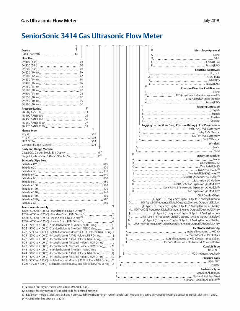
July 2019Gas Ultrasonic Flow Meter
Metrology Approval
A NoneB OIMLC China (CPA)F . . . . . . . . . . . . . . . . . . . . . . . . . . . . . . . . . . . . . . . . . . . . Russia (EAC)
Electrical Approvals1 UL / c-UL2 ATEX/IECEx3 INMETRO4 . . . . . . . . . . . . . . . . . . . . . . . . . . . . . . . . . . . . . . . . . . . Russia (EAC)
Pressure Directive Certification1 None 2 PED (must select electrical approval 2)3 CRN (Canadian Boiler Branch)4 .............................................................Russia (EAC)
Tagging Language1 English2 French3 Russian4 Chinese
Tagging Format (Line Size / Pressure Rating / Flow Parameters)1 Inch / ANSI / US Customary2 Inch / ANSI / Metric3 DN / PN / US Customary4 DN / PN Metric
WirelessA NoneB THUM
Expansion ModuleA NoneB One Serial RS232C One Serial RS485D . . . . . . . . . . . . . . . . . . . . . . . . . . . . . . . . . . . . . . . . . . . . . . . . . . Two Serial RS232(3)
E . . . . . . . . . . . . . . . . . . . . . . . . . . . . . . . . . . . . . . . . . . . Two Serial RS485 (2-wire)(3)
F . . . . . . . . . . . . . . . . . . . . . . . . . . . . . . . . . . . . . . . Serial RS232 and Serial RS485(3)
G. . . . . . . . . . . . . . . . . . . . . . . . . . . . . . . . . . . . . . . . . . . . . . . .Expansion I/O Module H . . . . . . . . . . . . . . . . . . . . . . . . . . . . . . .Serial RS-232 and Expansion I/O Module(3)
J. . . . . . . . . . . .. . . . . . . . . . . . .Serial RS-485 (2-wire) and Expansion I/O Module(3)
K . . . . . . . . . . . . . .. . . . . . . . . . . . . . . . . . . . . . . . . . . . .Two Expansion I/O Module(3)
CPU/Display/KeysC ..................... I/O Type 2 (3 Frequency/Digital Outputs, 2 Analog Outputs)D .......... I/O Type 2 (3 Frequency/Digital Outputs, 2 Analog Outputs)/DisplaysG . . . . . . . . I/O Type 2 (3 Frequency/Digital Outputs, 2 Analog Outputs)/CFA KeyH . . .I/O Type 2 (3 Frequency/Digital Outputs, 2 Analog Outputs)/Displays/CFA KeyJ . . . . . . . . . . . . . . . . . . I/O Type 4 (6 Frequency/Digital Outputs, 1 Analog Output)K . . . . . . . . . I/O Type 4 (6 Frequency/Digital Outputs, 1 Analog Output)/DisplaysM . . . . . . . . . I/O Type 4 (6 Frequency/Digital Outputs, 1 Analog Output)/CFA KeyN . . . . I/O Type 4 (6 Frequency/Digital Outputs, 1 Analog Output)/Displays/CFA Key
Electronics MountingA Integral Mount (up to +60°C)B Remote Mount w/15ft CablesE Integral Mount (up to +60°C) w/Armored CablesF . . . . . . . . . . . . . . . . . . . . . . . . . . . . . Remote Mount with 5ft Armored, Covered Cable
Conduit Type1 3/4-in NPT2 M20 (reducers required)
Pressure Taps1 1/2-in NPT3 Pipette
Enclosure Type 1 Standard Aluminum2 Optional Stainless Steel3 Optional (Retrofit) Aluminum(3)
Device3414 Four-Path 14
Line SizeDN100 (4-in) 04DN150 (6-in) 06DN200 (8-in) 08DN250 (10-in) 10DN300 (12-in) 12DN350 (14-in) 14DN400 (16-in) 16DN450 (18-in) 18DN500 (20-in) 20DN600 (24-in) 24DN650 (26-in) 26DN750 (30-in) 30DN900 (36-in)(1) 36
Pressure RatingPN 50 / ANSI 300 03PN 100 / ANSI 600 05PN 150 / ANSI 900 06PN 250 / ANSI 1500 07PN 420 / ANSI 2500 08
Flange TypeRF / RF S01RTJ / RTJ S02FEFA / FEFA S03Compact Flange (Special) S04
Body and Flange MaterialCast: LCC / Carbon Steel / SS / Duplex M(2)
Forged: Carbon Steel / 316 SS / Duplex SS F(2)
Schedule (Pipe Bore)Schedule LW LW0Schedule 20 020Schedule 30 030Schedule 40 040Schedule 60 060Schedule 80 080Schedule 100 100Schedule 120 120Schedule 140 140Schedule 160 160Schedule STD STDSchedule XS XS0
Transducer AssemblyT200 (-50°C to +125°C) - Standard Stalk, NBR O-ring(4) 1T200 (-40°C to +125°C) - Standard Stalk, FKM O-ring(4) 2T200 (-50°C to +125°C) - Inconel Stalk, NBR O-ring(4) 3T200 (-40°C to +125°C) - Inconel Stalk, FKM O-ring(4) 4T-21 (-20°C to +100°C) - Standard Mounts / Holders, NBR O-ring GT-22 (-50°C to +100°C) - Standard Mounts / Holders, NBR O-ring HT-22 (-50°C to +100°C) - Isolated Standard Mounts / 316L Holders, NBR O-ring IT-21 (-20°C to +100°C) - Inconel Mounts / 316L Holders, NBR O-ring JT-22 (-50°C to +100°C) - Inconel Mounts / 316L Holders, NBR O-ring KT-21 (-20°C to +100°C) - Inconel Mounts / Inconel Holders, FKM O-ring LT-22 (-50°C to +100°C) - Inconel Mounts / Inconel Holders, FKM O-ring MT-41 (-50°C to +100°C) - Standard Mounts / Holders, NBR O-ring NT-41 (-50°C to +100°C) - Inconel Mounts / 316L Holders, NBR O-ring QT-41 (-40°C to +100°C) - Inconel Mounts / Inconel Holders, FKM O-ring ST-22 (-50°C to +100°C) - Isolated Inconel Mounts / 316L Holders, NBR O-ring YT-22 (-40°C to +100°C) - Isolated Inconel Mounts / Inconel Holders, FKM O-ring Z
(1) Consult factory on meter sizes above DN900 (36-in).(2) Consult factory for specific model code for desired material. (3) Expansion module selections D, E and F only available with aluminum retrofit enclosure. Retrofit enclosure only available with electrical approval selections 1 and 2. (4) Available for line sizes up to 12-in.
SeniorSonic 3414 Gas Ultrasonic Flow Meter

August 2019Daniel SeniorSonic 3414
www.Emerson.com 16

www.Emerson.com 17
DatasheetGas Ultrasonic Flow Meter

Emerson Automation Solutions
Daniel Measurement and Control, Inc. North America / Latin America: Headquarters USA - Houston, Texas T +1.713.467.6000 USA Toll Free 1.888.FLOW.001
www.Emerson.com/Daniel
Middle East, Africa: Dubai, UAE T +971.4.811.8100 Asia Pacific: Singapore T +65.6777.8211
©2019 Daniel Measurement and Control, Inc. All Rights Reserved. Unauthorized duplication in whole or in part is prohibited. Printed in the USA. DAN-GUSM-3414-DS-0819
The Emerson logo is a trademark and service mark of Emerson Electric Co. Daniel Measurement and Control, Inc. ("Daniel") is an Emerson Automation Solutions business unit and a subsidiary of Daniel Industries, Inc. The Daniel name and logo are trademarks of Daniel Industries, Inc. All other trademarks are the property of their respective companies.