Foundry - Kracht · In addition to furnaces for foundry, ... 3 x K 300/1 with work platform for...
40
www.nabertherm.com Foundry Melting Holding Transporting Core Drying Thermal Decoring Dewaxing Heat Treatment Annealing Tempering Preheating Quenching Made in Germany
Transcript of Foundry - Kracht · In addition to furnaces for foundry, ... 3 x K 300/1 with work platform for...
www.nabertherm.com
Foundry
MeltingHoldingTransportingCore DryingThermal DecoringDewaxingHeat TreatmentAnnealingTemperingPreheatingQuenching
MadeinGermany

Made in GermanyNabertherm with more than 350 employees worldwide have been developing and producing industrial furnaces for many different applications for over 60 years. 150,000 satisfied customers in 100 countries offer proof of our commitment to build quality equipment cost-effectively. Short delivery times are ensured due to our complete inhouse production and our wide variety of standard furnaces.
Setting Standards in Quality and ReliabilityOur products range from standard furnaces to flexible, state-of-the-art fully automatic systems and plants with material handling technology. Your complete heat treatment production process can be realized through our customized solutions.
Innovative Nabertherm control technology provides for precise control as well as full documentation and remote monitoring of your processes. Our engineers apply state-of-the-art technology to improve the temperature uniformity, energy efficiency, reliability and durability of our systems with the goal of enhancing your competitive edge.
Global Sales and Service Network – Close to youWith our global sales network, we can offer on-site customer service wherever you choose to produce. Long term sales and distribution partners in all important world markets ensure individual on-site customer service and consultation. There are various reference customers in your neighborhood who have similar furnaces or systems.
Customer Service and Spare PartsOur professional service engineers are available for you world-wide. Due to our complete inhouse production, we can despatch spare parts from stock or produce with short delivery time.
More Than Heat – Experience in Many Fields of Thermal ProcessingIn addition to furnaces for foundry, Nabertherm offers a wide range of standard furnaces and systems for many other thermal processing applications. The modular design of our products allows us to customize a solution to your individual needs without expensive modifications. Our professional R&D department will be pleased to test your product samples in order to specify the right heat treatment equipment for you.
�

Contents
PageMelting and Holding FurnacesTilting crucible furnaces KB, gas or oil fired, for melting and holding ............................................................... 4 Tilting crucible furnaces K (brick insulation) and KF (fiber insulation), electrically heated, for melting and holding .. 6 Tilting crucible furnace KC and crucible furnace TC, SiC-rod-heated, for melting and holding ............................. 8 Crucible furnaces TB, gas or oil fired, for melting and holding .......................................................................10 Exhaust gas discharge for gas or oil fired crucible furnace ............................................................................1� Alternative heating concepts, holding furnaces with immersion heaters ..........................................................1�
Crucible furnaces TBR, gasfired with recuperator burner, for energy-saving melting and holding .........................13 Crucible furnaces T (brick insulation) and TF (fiber insulation), electrically heated, for melting and holding ..........14Bale-out crucible furnaces T ../10, electrically heated, for holding .................................................................16Bath furnaces B, electrically heated, for holding ..........................................................................................17 Accessories for bale-out and tilting crucible furnaces ................................................................................. 18 Control and documentation alternatives for melting furnaces ........................................................................ �0
Tilting crucible furnaces with electrohydraulic lifting platforms ...................................................................... �� Combi transport ladle for melting, holding, and transporting ........................................................................ �� Transportable crucible furnaces T and TF .................................................................................................. �� Rotary table system for continuous pouring ............................................................................................... �3 Melting furnaces for heavy metals ............................................................................................................ �3 Magnesium melting furnaces ................................................................................................................... �3
Dewaxing Furnaces, Electrically Heated (N/WAX) or Gas-Fired (NB/WAX) ......................................... �4
Furnaces for Core Drying, Thermal Decoring, and PreheatingChamber furnaces, electrically heated (N) or gas-fired (NB) ......................................................................... �6Bogie hearth furnaces, electrically heated (W) or gas-fired (WB) .................................................................. �8
Heat Treatment FurnacesBogie hearth furnaces, electrically heated (W) or gas-fired (WB), for annealing............................................... 30 Rotary hearth furnaces for preheating and sintering of molds ....................................................................... 3� Salt bath furnaces, electrically heated (TS) or gas-fired (TSB), for the heat treatment of steel or light metals ...... 33
Tempering Plants for Steel and Aluminum ........................................................................................... 34
Professional Control and Documentation Alternatives ........................................................................ 38
3

Tilting Crucible Furnaces KB, Gas or Oil Fired,for Melting and Holding
Hydraulics assembly with nonflammable hydraulic fluid
Two-stage burner, fixed on furnace frame
The gas or oil fired tilting crucible furnaces of the KB series are characterized by their high melting performance. They are perfectly suited for the melting of aluminum and other nonferrous alloys. The use of high-quality insulation materials results in very low power requirements. The two-stage burner can be configured for either gas operation or oil operation.
KB../1� with maximum furnace chamber temperature of 1�00 °C for aluminum or zincKB../14 with maximum furnace chamber temperature of 1400 °C suitable for bronze alloys or brass, with a maximum melt temperature of 1300 °CFuel heating using gas or oilTwo-stage power control: high load for melting operation, low load for holding mode, with automatic switchingPositive pressure in the furnace chamber keeps air out for high-efficiency operationGas system consisting of pressure regulator, gas filter, manometer, and solenoidsLow NOx emissionsBurner flame continuously monitoredBurner technology with service-friendly construction, e.g. flame head easily removable when the burner is swung outBurner technology manufactured in compliance with EN/DIN 746 part �High melting power due to powerful burner and high-quality insulationInsulation constructed in multiple layers with lightweight refractory bricks in the furnace chamberCrucible of clay-graphite up to KB �40, or isostatically pressed clay-graphite or SiC from KB 360 and upElectrohydraulic tilting system with nonflammable ultra-safe hydraulic fluidSafe, even, and precise pouring due to optimum pivot point in the furnace and manual throttling valve operation of the hydraulic systemEmergency outlet for safe draining of the melt in case of crucible breakageExhaust gas discharge over the crucible edge, resulting in about �0% higher melting performance than with side exhaust gas discharge. Swing lid as optionIntegrated safety system which continues to operate the furnace at reduced power in case of malfunction in the bath thermocouple, in order to prevent the freezing of the meltOver-temperature limit controller in furnace chamber for protection against overheating. The limiter switches the heating off when the set limit temperature is reached, and only switches it back on after the temperature has fallen againFurnace chamber control with temperature measurement behind the crucible, recommended for melting For Information on temperature regulation, see pages �0/�1
Melting system with two furnaces KB 360/1� and work platform
4

KB 400/1�
Model Tmax Crucible Capacity Melting performance³
Consumption holding
lid closed
ConsumptionMelting
Burner rating
Exterior dimensionsin mm
Weight
°C Kg Al Kg Cu Kg Al/hr Kg Cu/hr KWh/h KWh/kg kW W D H kgAl
KB 80/1� 1�00 TP �87 180 550 ��0¹ - 10 1,3 - 1,5 300 �030 1700 1510 1800KB 150/1� 1�00 TP 41� 330 970 �40¹ - 11 1,3 - 1,5 300 �140 1900 1710 ��00KB 180/1� 1�00 TP 41� H 370 1�00 �60¹ - 13 1,3 - 1,5 300 �140 1900 1810 �400KB �40/1� 1�00 TP 587 570 - 400¹ - 15 1,3 - 1,5 390 �650 �030 1810 �600KB 360/1� 1�00 TBN 800 750 - 4�0¹ - 17 1,3 - 1,5 450 �650 �080 1910 �900KB 400/1� 1�00 TBN 1100 1000 - 450¹ - 19 1,3 - 1,5 450 �650 �080 �080 3300
KB 40/14 1400 R 400/TP 98� 1�0 400 - 330² �� 1,0 - 1,3 400 �070 1700 1770 �300KB 60/14 1400 R 500 150 500 - 360² �5 1,0 - 1,3 400 �070 1900 1810 �500KB 80/14 1400 R 600 180 600 - 380² �5 1,0 - 1,3 400 �070 1900 1910 �650¹At 700 °C ²At 1000 °C³The specified melting performances are maximum values. In practice, approx. 80 % are achieved.
KB 180/1� in production
Additional EquipmentCrucible of isostatically pressed clay-graphite or SiC with higher thermal conductivity up to KB �40Side exhaust gas discharge with swing lid, with the following features:
high melt quality due to lower burnofflower hydrogen absorption in the meltreduction of power consumption due to swing lid in holding modeoperator exposed to less heat in the area above the crucibleabout �0% lower melting performance compared with exhaust gas discharge over the crucible edge
Insulated connection piece for side exhaust gas discharge to connect exhaust ductworkExhaust gas collection hood for furnaces with exhaust gas discharge over the crucible edgeWork platformCrucible breakage monitor with visual and audible signal (only for models KB ../1�)Modulating burner with precise temperature control for optimum quality of the melt in holding modeBath control with thermocouples in the furnace chamber and in the melt. The furnace temperature is controlled through the melt. Temperature overshoots are reduced, thus the quality of the melt is improvedFor information on other accessories, see pages 18/19
-----
Insulated connection piece for side exhaust gas discharge to connect exhaust ductwork
5
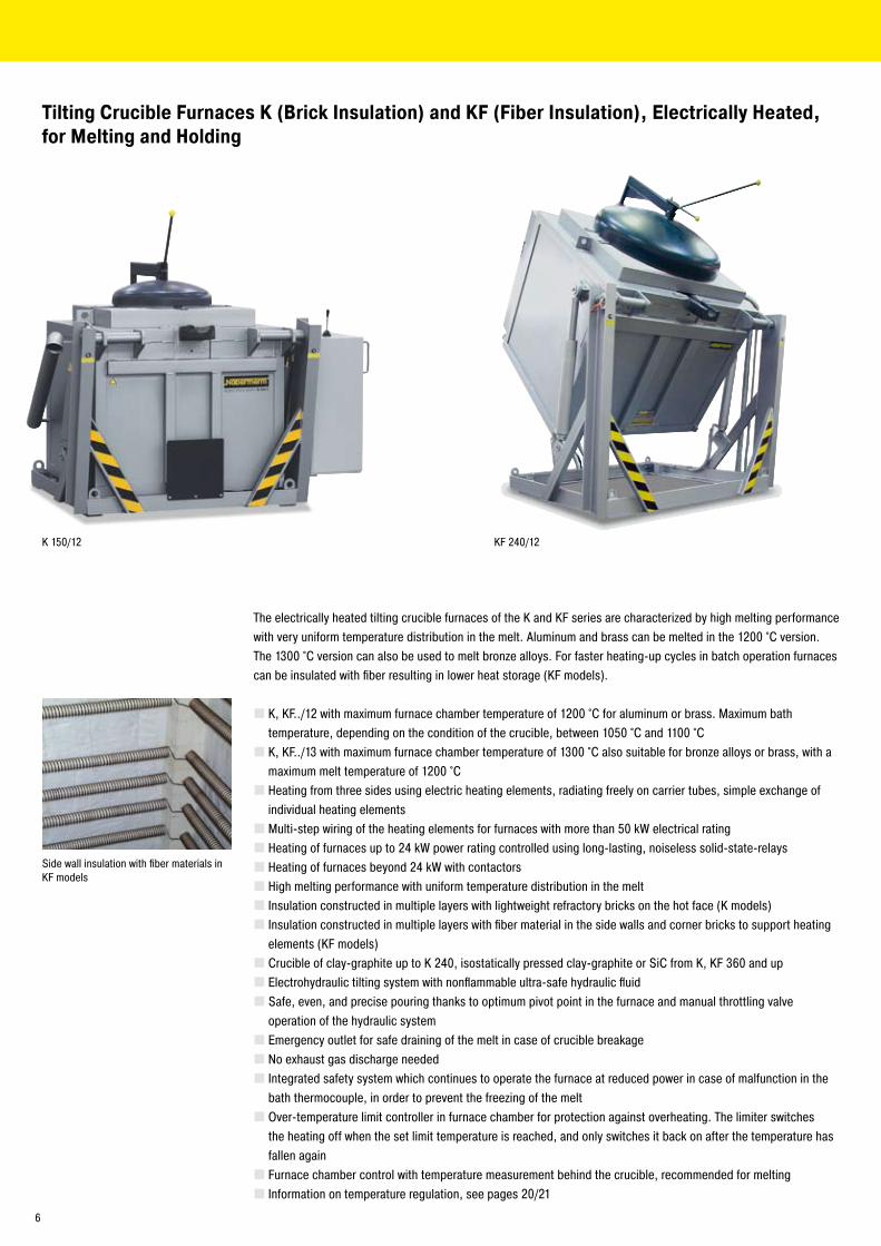
K 150/1� KF �40/1�
Tilting Crucible Furnaces K (Brick Insulation) and KF (Fiber Insulation), Electrically Heated, for Melting and Holding
Side wall insulation with fiber materials in KF models
The electrically heated tilting crucible furnaces of the K and KF series are characterized by high melting performance with very uniform temperature distribution in the melt. Aluminum and brass can be melted in the 1�00 °C version. The 1300 °C version can also be used to melt bronze alloys. For faster heating-up cycles in batch operation furnaces can be insulated with fiber resulting in lower heat storage (KF models).
K, KF../1� with maximum furnace chamber temperature of 1�00 °C for aluminum or brass. Maximum bath temperature, depending on the condition of the crucible, between 1050 °C and 1100 °CK, KF../13 with maximum furnace chamber temperature of 1300 °C also suitable for bronze alloys or brass, with a maximum melt temperature of 1�00 °CHeating from three sides using electric heating elements, radiating freely on carrier tubes, simple exchange of individual heating elementsMulti-step wiring of the heating elements for furnaces with more than 50 kW electrical ratingHeating of furnaces up to �4 kW power rating controlled using long-lasting, noiseless solid-state-relaysHeating of furnaces beyond �4 kW with contactorsHigh melting performance with uniform temperature distribution in the meltInsulation constructed in multiple layers with lightweight refractory bricks on the hot face (K models)Insulation constructed in multiple layers with fiber material in the side walls and corner bricks to support heating elements (KF models)Crucible of clay-graphite up to K �40, isostatically pressed clay-graphite or SiC from K, KF 360 and upElectrohydraulic tilting system with nonflammable ultra-safe hydraulic fluidSafe, even, and precise pouring thanks to optimum pivot point in the furnace and manual throttling valve operation of the hydraulic systemEmergency outlet for safe draining of the melt in case of crucible breakageNo exhaust gas discharge neededIntegrated safety system which continues to operate the furnace at reduced power in case of malfunction in the bath thermocouple, in order to prevent the freezing of the meltOver-temperature limit controller in furnace chamber for protection against overheating. The limiter switches the heating off when the set limit temperature is reached, and only switches it back on after the temperature has fallen againFurnace chamber control with temperature measurement behind the crucible, recommended for melting Information on temperature regulation, see pages �0/�1
6

3 x K 300/1� with work platform for melting of aluminum
Charging of transport ladle with K 360/1�
Model Tmax Crucible Capacity Exterior dimensionsin mm
Power Weight Melting performance³
Holdinglid closed/open
°C Kg Al Kg Cu W D H in kW kg kg/hr Al kg/h Cu (kW)K, KF 10/1� 1�00 A 70 �0 70 1510 1�40 1040 16 750 3�¹ 47² 3/7¹K, KF �0/1� 1�00 A 150 45 150 1660 1360 1060 �0 940 4�¹ 63² 3/7¹K, KF 40/1� 1�00 A 300 90 300 1740 1470 1140 �6 1�70 58¹ 84² 3/7¹K, KF 80/1� 1�00 TP �87 180 550 1800 1700 1180 50 1430 1�6¹ 190² 4/10¹K, KF 150/1� 1�00 TP 41� 330 970 1870 1900 1460 60 1800 147¹ ��0² 5/1�¹K, KF �40/1� 1�00 TP 587 570 - �010 �000 1460 80 ��90 �10¹ - 8/17¹K, KF 300/1� 1�00 TP 587H 650 - �010 �000 1560 80 �400 �10¹ - 9/18¹K, KF 360/1� 1�00 BUK 800 750 - �1�0 �100 1550 100 �780 �60¹ - 11/�0¹K, KF 400/1� 1�00 TBN 1100 1050 - �1�0 �100 1700 1�6 3030 �95¹ - 1�/��¹
K, KF 10/13 1300 A 70 �0 70 1510 1�40 1040 16 800 3�¹ 47² 5/8²K, KF �0/13 1300 A 150 45 150 1660 1360 1060 �0 1040 4�¹ 63² 5/8²K, KF 40/13 1300 A 300 90 300 1740 1470 1140 �6 1350 58¹ 84² 5/8²K, KF 80/13 1300 TP �87 180 550 1800 1700 1180 50 1600 1�6¹ 190² 6/11²¹At 700 °C ²At 1000 °C³The specified melting performances are maximum values. In practice, approx. 80 % are achieved.
Additional EquipmentCrucible of isostatically pressed clay-graphite or SiC with higher thermal conductivity up to K, KF �40Work platformCrucible breakage monitor with visual and audible signal (only for models K, KF ../1�)Bath control with thermocouples in the furnace chamber and in the melt. The furnace temperature is controlled through the melt. Temperature overshoots are reduced, thus the quality of the melt is improvedHeating system operated through thyristors in phase-angle mode assures even power from heating elementsMulti-step switching of the furnace heat (see page �1). In holding mode, a switch or the controller is used to turn off one heating section in order to reduce the electrical ratingHigher electrical ratings to increase melting performanceFor information on other accessories, see pages 18/19
7

KC 180/14
Tilting Crucible Furnace KC and Crucible Furnace TC, SiC-Rod-Heated, for Melting and Holding
Heated on both sides by high performance SiC rods
The electrically heated tilting crucible and bale-out furnaces of the KC and TC series are characterized by a higher melting performance than achievable with wire heated melting furnaces. These furnaces are designed for permanent operation at working temperatures.
Maximum furnace chamber temperature of 1450 °C, also suitable for bronze alloys with a maximum melt temperature of up to 13�0 °C, subject to the condition of crucibleHeating from two sides by generously dimensioned SiC rods, uniform temperature distributionSimple exchange of individual heating elementsHeat operation by thyistors in phase-angle mode with performance control:The resistance of the SiC rods changes with temperature and age. Performance control ensures constant power of heating irrespective to the condition of the heating elements.High melting performance with uniform temperature distributionInsulation constructed in multiple layers with lightweight refractory bricks on the hot faceSiC-CrucibleElectrohydraulic tilting system with nonflammable ultra-safe hydraulic fluid for KC modelsSafe, even, and precise pouring thanks to optimum pivot point in the furnace and manual throttling valve operation of the hydraulic systemEmergency outlet for safe draining of the melt in case of crucible breakageNo exhaust gas discharge neededIntegrated safety system which continues to operate the furnace at reduced power in case of malfunction in the bath thermocouple, in order to prevent the freezing of the meltOver-temperature limit controller in furnace chamber for protection against overheating. The limiter switches the heating off when the set limit temperature is reached, and only switches it back on after the temperature has fallen againFurnace chamber control with temperature measurement behind the crucible, recommended for melting For Information on temperature regulation, see pages �0/�1
Wiring of the heating elements in sections above each other
8

TC 80/14 KC 150/14
Additional EquipmentWork platform for simplified loadingFor information on other accessories, see pages 18/19
Model Tmax Crucible Capacity Exterior dimensions in mm Power Weight Melting performance³°C Kg Al Kg Cu W D H in kW kg kg/hr Al kg/h Cu
KC �0/14 1450 A 150 45 150 1710 1900 1050 36 1500 80¹ 1�0²KC 40/14 1450 A 300 90 300 1770 1900 1100 36 1600 80¹ 1�0²KC 80/14 1450 TCP �87 �00 650 1880 1970 1160 48 1900 1�0¹ 180²KC 150/14 1450 TCP 41� 300 1000 �000 �070 1300 66 �700 140¹ ��0²KC 180/14 1450 TCP 41�H - 1000 �000 �070 1500 99 3000 - �30²
TC �0/14 1450 A 150 45 150 1�00 1�50 930 36 830 80¹ 1�0²TC 40/14 1450 A 300 90 300 1�60 1�50 10�0 36 950 80¹ 1�0²TC 80/14 1450 BU �00 �00 650 1360 1350 1080 48 1050 1�0¹ 180²TC 150/14 1450 BU 300 300 1000 1450 13�0 1300 66 1300 140¹ ��0²¹At 700 °C ²At 1000 °C³The specified melting performances are maximum values. In practice, approx. 80 % are achieved.
Switchgear with thyristors in phase angle operation for economic power consumption
Swing lid with good sealing to collar plate to avoid heat loss over the crucible opening
9

TB �0/14 TB �40/1�
Crucible Furnaces TB, Gas or Oil Fired, for Melting and Holding
Two-step gas burner for low-load and high-load mode
Emergency outlet for the safe draining of melt in case of crucible breakage
The gas or oil fired crucible furnaces of the TB series are characterized by their high melting performance. They are the work horse for melting operation but also for holding of aluminum and zinc. The use of high-quality insulation materials results in very low power consumption. The two-step burner can laid-out for either gas operation or oil operation.
TB../1� with maximum furnace chamber temperature of 1�00 °C for aluminum or zincTB../14 with maximum furnace chamber temperature of 1400 °C suitable for bronze alloys or brass, with a maximum melt temperature of 1300 °CFuel heating using gas or oilTwo-step power regulation: high load for melting operation, low load for holding mode, with automatic switchingPositive pressure in the furnace chamber keeps air out for high-efficiency operationGas system consisting of pressure regulator, gas filter, manometer, and solenoidsBurner flame continuously monitoredBurner technology with service-friendly construction, e.g. flame head easily removable when the burner is swung outBurner technology manufactured in compliance with EN/DIN 746 part �High melting power due to powerful burner and high-quality insulationMulti-layer insulation with lightweight refractory bricks on the hot face, 1400 °C models with additional wear and tear layer consisting of copper-resistant high-performance concreteEmergency outlet for safe draining of the melt in case of crucible breakage
10

TB �40/1�
Model Tmax Crucible Capacity Melting performance³
Consumption holding lid closed
UseMelting
Burner rating
Exterior dimensionsin mm
Weight
°C Kg Al Kg Cu kg/hr Al kg/h Cu KWh/h KWh/kg kW W D H kgAl
TB 80/1� 1�00 BU �00 �00 650 140¹ - 10 1,3 - 1,5 180 1�00 1870 1�40 900TB 100/1� 1�00 BU �50 �50 830 140¹ - 11 1,3 - 1,5 180 1310 1980 1380 1000TB 110/1� 1�00 BU 300 300 1000 150¹ - 13 1,3 - 1,5 �10 1310 1980 1510 1�00TB 150/1� 1�00 BU 350 350 1150 ��0¹ - 15 1,3 - 1,5 300 1310 1980 1550 1400TB 180/1� 1�00 BU 500 500 1650 �70¹ - 17 1,3 - 1,5 300 1450 �140 1560 1700TB �40/1� 1�00 BU 600 600 �000 330¹ - 19 1,3 - 1,5 390 1490 �180 1700 1900TB 360/1� 1�00 BN 800 800 - 350¹ - �0 1,3 - 1,5 400 1590 ��80 1800 �000TB 400/1� 1�00 BN 900 900 - 350¹ - �� 1,3 - 1,5 400 1590 ��80 1900 �100TB 500/1� 1�00 BU 1�10 1�00 - 350¹ - �3 1,3 - 1,5 400 1690 �380 1850 �300TB 600/1� 1�00 BU 1310 1300 - 4�0¹ - �5 1,3 - 1,5 500 1690 �380 �000 �400TB 650/1� 1�00 BU 1810 1400 - 4�0¹ - �6 1,3 - 1,5 500 1760 �450 1630 �300TB 700/1� 1�00 BU 1510 1500 - 4�0¹ - �8 1,3 - 1,5 500 1690 �380 �1�0 �600TB 800/1� 1�00 BU 1810 1800 - 440¹ - 30 1,3 - 1,5 500 1760 �450 �100 �800
CuTB 10/14 1400 A 100 30 100 - 90² �� 1,0 - 1,3 �10 980 1590 1190 1000TB �0/14 1400 A 150 45 150 - 100² �� 1,0 - 1,3 �10 1080 1870 1310 1�50TB 40/14 1400 A 400 1�0 400 - 300² �5 1,0 - 1,3 300 1�10 �000 1460 1500TB 60/14 1400 A 500 150 500 - 3�0² �5 1,0 - 1,3 3�0 1�10 �000 1510 1600TB 80/14 1400 A 600 180 600 - 3�0² �5 1,0 - 1,3 3�0 1�60 �050 1540 1750¹At 700 °C ²At 1000 °C³The specified melting performances are maximum values. In practice, approx. 80 % are achieved.
TB 80/1� with side exhaust gas discharge
TB 40/14 with crucible pulling feature
Exhaust gas discharge over the crucible edge, resulting in about �0% higher melting performance than with side exhaust gas discharge, swing lid as optionSide exhaust gas discharge for TB ../1� models, see Additional Equipment below for featuresIntegrated safety system which continues to operate the furnace at reduced power in case of malfunction in the bath thermocouple, in order to prevent the freezing of the meltOver-temperature limit controller in furnace chamber for protection against overheating. The limiter switches the heating off when the set limit temperature is reached, and only switches it back on after the temperature has fallen againFurnace chamber control with temperature measurement behind the crucible, recommended for meltingFor Information on temperature regulation, see pages �0/�1
Additional EquipmentCrucible of clay-graphite or SiC with high thermal conductivitySide exhaust gas discharge with swing or flap lid, with the following features:
high melt quality due to lower burnofflower hydrogen absorption in the meltreduction of power consumption due to swing lid in holding modeoperator exposed to less heat in the area above the crucibleabout �0% lower melting performance compared with exhaust gas discharge over the crucible edge
Insulated connection piece for side exhaust gas discharge to connect exhaust ductworkExhaust gas collection hood for furnaces with exhaust gas discharge over the crucible edgeWork platformCrucible breakage monitor with visual and audible signal (only for models TB ../1�)Modulating burner with precise temperature control for optimum quality of the melt in holding modeBath control with thermocouples in the furnace chamber and in the melt. The furnace temperature is controlled through the melt. Temperature overshoots are reduced, thus the quality of the melt is improvedCrucible pulling feature for models up to TB 40/14 with special swinging collar plateFor information on other accessories, see pages 18/19
-----
Insulated connection piece for side exhaust gas discharge to connect exhaust ductwork
11

Exhaust Gas Discharge for Gas or Oil Fired Crucible Furnaces
Exhaust Gas Discharge over the Crucible EdgeExhaust gas discharge over the crucible edge is a standard feature of our gas or oil fired crucible furnaces, with the exception of the TB models for 1�00 °C furnace chamber temperature, because these furnaces are often also used for holding. Exhaust gas discharge over the crucible edge offers the following advantages:
Very high melting performanceLow power consumption, since the crucible is not only heated from outside, but also additionally from the top.
to flue
Exhaust gas
Crucible
Burner
Side exhaust gas discharge
Extraction hood
Exhaust gases
Crucible
Burner
Exhaust gas discharge over the crucible edge
Immersion heating element for direct bath heating
Subject to the specific application, direct heating with immersion heaters can be a practical alternative to an electrically heated holding furnace with indirect heating outside the crucible. Heating takes place through a powerful immersion heater which is introduced from above directly into the open crucible. This system has the following features:
Good energy utilization due to direct heatingVery high melt quality due to precise temperature controlOnly a small gap is needed between the crucible and the furnace wall, thus the furnace can be smaller or crucible might be larger with same outer furnace dimensionsImmersion heating element might turn-out as obstacle during bale-outHigh wear & tear of heating elementsSubstantial heat loss due to operation without lid
Alternative Heating ConceptsHolding Furnaces with Immersion Heaters
Side Exhaust Gas DischargeSide exhaust gas discharge is available for all gas and oil fired crucible furnaces as optional equipment. Although the melting performance is not as high as for exhaust gas discharge over the crucible edge, this alternative offers the following advantages:
High melt quality due to lower burnoffLower hydrogen absorption in the meltReduction of power consumption due to swing lid in holding modeOperator exposed to less heat in the area above the crucible
1�
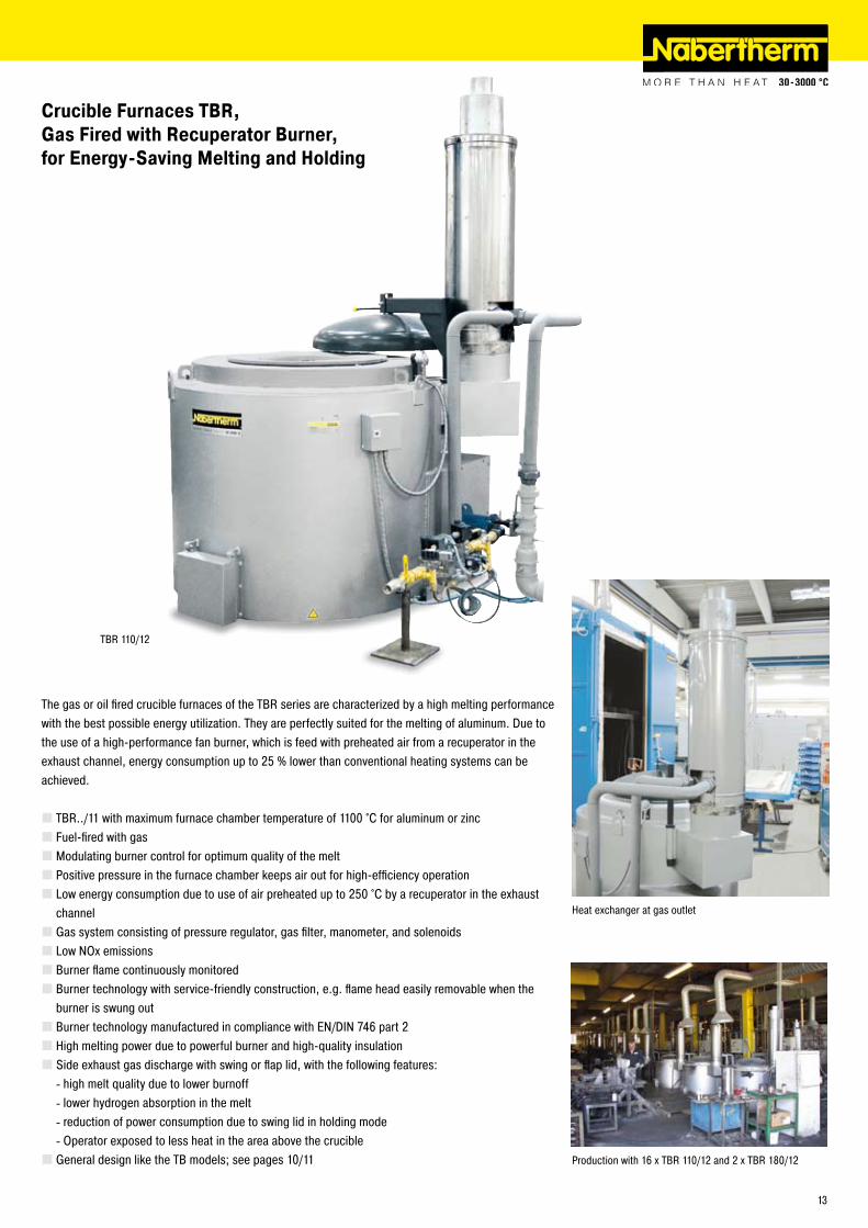
TBR 110/1�
Crucible Furnaces TBR, Gas Fired with Recuperator Burner, for Energy-Saving Melting and Holding
The gas or oil fired crucible furnaces of the TBR series are characterized by a high melting performance with the best possible energy utilization. They are perfectly suited for the melting of aluminum. Due to the use of a high-performance fan burner, which is feed with preheated air from a recuperator in the exhaust channel, energy consumption up to �5 % lower than conventional heating systems can be achieved.
TBR../11 with maximum furnace chamber temperature of 1100 °C for aluminum or zincFuel-fired with gasModulating burner control for optimum quality of the meltPositive pressure in the furnace chamber keeps air out for high-efficiency operationLow energy consumption due to use of air preheated up to �50 °C by a recuperator in the exhaust channelGas system consisting of pressure regulator, gas filter, manometer, and solenoidsLow NOx emissionsBurner flame continuously monitoredBurner technology with service-friendly construction, e.g. flame head easily removable when the burner is swung outBurner technology manufactured in compliance with EN/DIN 746 part �High melting power due to powerful burner and high-quality insulationSide exhaust gas discharge with swing or flap lid, with the following features:
high melt quality due to lower burnofflower hydrogen absorption in the meltreduction of power consumption due to swing lid in holding modeOperator exposed to less heat in the area above the crucible
General design like the TB models; see pages 10/11
----
Heat exchanger at gas outlet
Production with 16 x TBR 110/1� and � x TBR 180/1�
13

TF 150/1�
Crucible Furnaces T (Brick Insulation) and TF (Fiber Insulation), Electrically Heated, for Melting and Holding
Four side heating for excellent temperature uniformity
Emergency outlet for the safe draining of melt in case of crucible breakage
The electrically heated crucible furnaces of the T and TF series are characterized by a good melting performance with excellent temperature uniformity in the melt. In the 1100 °C version, aluminum can be melted, and in the 1�00 °C version, brass can be melted. The 1300 °C version is designed for melting bronze alloys. For faster heat-up times in batch operation, furnaces can alternatively be fiber insuated with low heat storage (TF models).
T, TF../11 with maximum furnace chamber temperature of 1100 °C for aluminum or zinc. Maximum melt temperatures, depending on the condition of the crucible, between 950 °C and 980 °CT, TF../1� with maximum furnace chamber temperature of 1�00 °C also suitable for brass. Maximum melt temperatures, depending on the condition of the crucible, between 1050 °C and 1100 °CT, TF../13 with maximum furnace chamber temperature of 1300 °C, also suitable for bronze alloys. Maximum melt temperatures, depending on the condition of the crucible, between 1150 °C and 1�00 °CFour-side heating using electric heating elements, freely radiating on carrier tubesSimple replacement of individual heating elements. In case of crucible breakage, only the defective heating elements on each level need to be replacedHeating of furnaces up to �4 kW power rating controlled using long-lasting, noiseless solid-state-relaysHeating of furnaces beyond �4 kW with contactorsHigh melting performance with uniform temperature distribution in the meltInsulation constructed in multiple layers with lightweight refractory bricks on the hot face (T models)Insulation constructed in multiple layers with fiber material in the side walls and corner bricks to support heating elements (TF models)Emergency outlet for safe draining of the melt in case of crucible breakageNo exhaust gas discharge neededIntegrated safety system which continues to operate the furnace at reduced power in case of malfunction in the bath thermocouple, in order to prevent the freezing of the meltOver-temperature limit controller in furnace chamber for protection against overheating. The limiter switches the heating off when the set limit temperature is reached, and only switches it back on after the temperature has fallen againFurnace chamber control with temperature measurement behind the crucible, recommended for meltingCrucible not included in the standard versionFor Information on temperature regulation, see pages �0/�1
T �40/1� with pneumatic lid opening
14

Model Tmax Crucible Capacity Exterior dimensions in mm Power Weight Melting performance³
Holdinglid closed/open
°C Kg Al Kg Cu W D H in kW kg kg/hr Al kg/h Cu (kW)T, TF 10/11 1100 A 70 �0 - 860 860 790 16 400 3�¹ - 3/5¹T, TF �0/11 1100 A 150 45 - 940 940 790 �0 460 4�¹ - 3/6¹T, TF 40/11 1100 A 300 90 - 1010 1010 880 �6 580 58¹ - 3/7¹T, TF 80/11 1100 BU �00 �00 1110 1110 940 50 650 1�6¹ - 4/9¹T, TF 110/11 1100 BU 300 300 - 1�00 1�00 1040 60 880 136¹ - 5/10¹T, TF 150/11 1100 BU 350 350 - 1�00 1�00 1�50 60 900 147¹ - 5/10¹T, TF 180/11 1100 BU 500 500 - 1370 1370 1�50 70 1080 168¹ - 7/15¹T, TF �40/11 1100 BU 600 600 - 1370 1370 1350 80 1�00 �10¹ - 7/15¹T, TF 360/11 1100 BN 800 800 - 1510 1510 1490 110 �000 �00¹ - 8/17¹T, TF 400/11 1100 BN 900 900 - 1510 1510 1590 110 �100 �00¹ - 10/�0¹T, TF 500/11 1100 BN 1�00 1�00 - 1510 1510 1640 110 �450 �00¹ - 11/�1¹T, TF 600/11 1100 BU 1310 1300 - 1615 1615 1730 110 �550 �00¹ - 13/�3¹T, TF 650/11 1100 BP 1000 1400 - 1685 1685 1360 110 �400 �40¹ - 13/�0¹T, TF 700/11 1100 BU 1510 1500 - 1615 1615 1850 140 �750 �40¹ - 13/�3¹T, TF 800/11 1100 BU 1800 1800 - 1685 1685 1830 140 �800 �40¹ - 15/�5¹
T, TF 10/1� 1�00 A 70 �0 70 860 860 770 16 440 3�¹ 47² 5/8²T, TF �0/1� 1�00 A 150 45 150 940 940 770 �0 5�0 4�¹ 63² 5/10²T, TF 40/1� 1�00 A 300 90 300 1010 1010 860 �6 600 58¹ 84² 5/1�²T, TF 80/1� 1�00 BU �00 �00 650 1110 1110 930 50 760 1�6¹ 190² 5/15²
T, TF 10/13 1300 A 70 �0 70 900 900 890 16 600 3�¹ 47² 5/8²T, TF �0/13 1300 A 150 45 150 980 980 890 �0 640 4�¹ 63² 5/10²T, TF 40/13 1300 A 300 90 300 1050 1050 970 �6 760 58¹ 84² 5/1�²T, TF 80/13 1300 BU �00 �00 650 1150 1150 1030 50 960 1�6¹ 190² 5/15²¹At 700 °C �At 1000 °C³The specified melting performances are maximum values. In practice, approx. 80 % are achieved.
� x T 360/11 with melt bath regulationAdditional EquipmentCrucible of clay-graphite or SiC with high thermal conductivityWork platformCrucible breakage monitor with visual and audible signal (only for models T, TF ../1�)Bath control with thermocouples in the furnace chamber and in the melt. The furnace temperature is controlled through the melt. Temperature overshoots are reduced, thus the quality of the melt is improvedHeating system operated through thyristors in phase-angle mode assures an even charging of heating elementsMulti-step switching of the furnace heat (see page �1). In holding mode, a switch or the controller is used to turn off one heating section in order to reduce the electrical ratingTransport function: Electrical plug connection on furnace and shock absorbers under the furnace for transport to pouring location (see page ��)Higher electrical ratings to increase melting performanceFor information on other accessories, see pages 18/19
15

T 150/10
Bale-Out Crucible Furnaces T ../10, Electrically Heated, for Holding
Model Tmax Crucible Capacity Exterior dimensions in mm Power Weight Melting performance²
Holdinglid closed/open
°C Kg Al Kg Cu W D H in kW kg kg/hr Al kg/h Cu (kW)T 80/10 1000 BU �00 �00 - 1150 1150 1030 �0 660
holding only
4/9¹T 110/10 1000 BU 300 300 - 1�40 1�40 1130 �6 890 5/10¹T 150/10 1000 BU 350 350 - 1�40 1�40 1�90 38 9�0 5/10¹T 180/10 1000 BU 500 500 - 1410 1410 1�90 4� 11�0 7/15¹T �40/10 1000 BU 600 600 - 1410 1410 1390 50 1�40 7/15¹T 360/10 1000 BN 800 800 - 1510 1510 1490 50 �000 8/17¹T 400/10 1000 BN 900 900 - 1510 1510 1590 50 �100 10/�0¹T 500/10 1000 BU 1�10 1�00 - 1615 1615 1580 50 �450 11/�1¹T 600/10 1000 BU 1310 1300 - 1615 1615 1730 50 �550 13/�3¹T 650/10 1000 BP 1000 1400 - 1685 1685 1360 60 �400 13/�0¹T 700/10 1000 BU 1510 1500 - 1615 1615 1850 60 �750 13/�3¹T 800/10 1000 BU 1800 1800 - 1685 1685 1830 70 �800 15/�5¹¹At 700 °C²The specified melting performances are maximum values. In practice, approx. 80 % are achieved.
Bale-out of T 650/10 with robot
Manual ladling from a T 80/10
Due to the particularly good insulation and reduced electrical rating, the furnaces of the T../10 series are perfectly suited for holding operation due to their great energy efficiency. Due to the reduced power rating only limited melting operation is possible.
Maximum furnace chamber temperature of 1000 °C, ideally suited for the holding of aluminumFour-side heating using electric heating elements, freely radiating on carrier tubesSimple replacement of individual heating elements. In case of crucible breakage, only the defective heating elements on each level need to be replacedHeating of furnaces up to �4 kW power rating controlled using long-lasting, noiseless solid-state-relaysHeating of furnaces beyond �4 kW with contactorsParticularly good insulation constructed in multiple layers with lightweight refractory bricks on the hot face Emergency outlet for safe draining of the melt in case of crucible breakageNo exhaust gas discharge neededCrucible not included in the standard versionIntegrated safety system which continues to operate the furnace at reduced power in case of malfunction in the bath thermocouple, in order to prevent the freezing of the meltOver-temperature limit controller in furnace chamber for protection against overheating. The limiter switches the heating off when the set limit temperature is reached, and only switches it back on after the temperature has fallen again.Furnace chamber control with temperature measurement behind the crucible, recommended for meltingFor Information on temperature regulation, see pages �0/�1For additional equipment, see T(F) furnaces, page 15
16

B �50 B 500
Bath Furnaces B, Electrically Heated, for Holding
Model Tmax Capacity Outer dimensions in mm Weight Ladle opening Power Holding °C Kg Al W D H kg mm kW kW
B 1�0 1000 300 1900 1150 1160 1900 300 x 300 11 �B �50 1000 600 �030 1�80 1�00 �450 380 x 380 14 3B 500 1000 1�00 �350 1450 1�40 3700 430 x 430 �0 5
Walled basin of a B �50
Special bricks in furnace chamber, multi-layered back-up insulation
Heating mounted in the lid, simple replace-ment of the heating elements
The bath furnaces B 1�0 - B 500 have been especially designed for stationary holding in die-casting, with bale-out by robot. The bath chamber of the furnace is lined with long-lasting special bricks. The multi-layered back-up insulation allows very low electrical rating to keep the melt warm. The furnace chamber is divided into three interconnected sections. The center section is heated with elements mounted in the lid . The ladle openings are dimensioned for optimum access by robot for bale-out. Properly used in holding mode, it can provide for a higher energy efficiency than bale-out furnaces.
Maximum furnace chamber temperature of 1000 °C, perfectly suited for holding of aluminum at about 7�0 °CHeating mounted in the lid, freely radiating from carrier tubesParticularly low energy consumption due to generously dimensioned, multi-layer insulationHigh melt quality due to very low corundum formation on the surfaceHeating switched by solid-state-relaysNo exhaust gas discharge neededTemperature control with measurement in the melt and in the furnace chamberPlug for connection with separate switchgear cabinetFor information on temperature control, see pages �0/�1
Additional EquipmentCustomized furnace sizesAdaptation to dosing pumpAutomated lid opening for ladling operationLadle opening adapted to size of ladleAlternative heating using immersion heaters for optimum melt quality (see page 1�)
17

Accessories for Bale-Out and Tilting Crucible Furnaces
Crucible Pulling Feature with Swinging Collar PlateIn standard version, Nabertherm crucible furnaces are built with a collar plate fixed to the furnace. The bale-out is done manually or by robot. As additional equipment, the smaller T .. models can be equipped with a swinging collar plate which allows crucible pulling. To pull the crucible, the collar plate is swung to the side, so that the operator has free access to the crucible from above.
Pneumatic Lid Opener for Bale-Out FurnacesThe Crucible furnaces of the T.. Series can be equipped with an optional pneumatic lid opener. The pneumatic lid opener is activated by depressing a foot pedal. Optionally, the pneumatic lid opener can be controlled and triggered by an external signal to fully automate the ladling process. The furnace lid swings to the side and the operator has free access to the crucible. This practical feature increases energy efficiency because the furnace is only open during charging and bale-out. Over 50% energy savings can be realized with the pneumatic lid opener vs. an always open furnace (see tables for energy consumption for each model of melting furnace).
Crucible Pulling Feature with swinging collar plate
Pneumatic lid opener
Charging funnel for ingots
Charging Funnel for IngotsEspecially for melting of ingots, the charging funnel, made of 1.4301 (304) stainless steel, is a handy tool for charging the furnace. Long ingots can also be loaded above the rim of the crucible taking a guided slide while sinking into the crucible. The charging funnel is suitable for all melting furnaces, whether electrically heated or gas-fired with a side exhaust gas discharge.
Work platform for K �40/1�
Work Platform for Loading for Bale-Out and Tilting Crucible FurnacesFor crucible and tilting crucible furnaces, customized work platforms for charging and servicing can be provided as additional equipment. This feature is used to simplify access to the furnace, particularly for larger furnace models. The operator has access to the top of the furnace to charge ingots or clean the melt.
18

Crucible breakage alarm device under the emergency outlet of a melting furnace
Separate bath temperature measurement device
Crucible Breakage Alarm DeviceNabertherm melting furnaces are equipped with emergency outlet. In case of crucible breakage or leaking melt the crucible breakage alarm device will provide for a warning as soon as fluid metal emerges from the emergency outlet. The warning signal of the alarm is both optical, with an signal lamp, and acoustic, using a horn.
Separate Bath Temperature Measurement DeviceFor melting furnaces with only furnace chamber temperature control, a separate bath temperature measurement device can be used to check the bath temperature. The measurement device is suitable for a temperature range from 0 to 1300 °C, and can be delivered with different dip pipe lengths (�00, 380, 610 mm). Temperature measurement is carried out using a NiCr-Ni thermocouple. The submersion length of the pipe whould be �/3 of the element length to achieve the most ideal reaction time. The average reaction time is 40 seconds. The thermocouple is suitable for all nonferrous metals except phosphor bronze.
Bath Control for Bale-Out and Tilting Crucible Furnaces (Cascade Control)In the basic version, the bale-out and tilting crucible furnaces of the T.. and K.. series are equipped with with a thermocouple in the furnace chamber behind the crucible. To achieve fast heat-up times the temperature is set significantly higher than the desired bath temperature. Therefore, this control allows very fast heating-up times, but results in considerable temperature overshoots in the melt due to the indirect temperature measurement.
As an option these furnaces can be equipped with a bath control system, which is particularly well-suited for holding operations. A second thermocouple in the bath is used in addition to the furnace chamber thermocouple to measure the bath temperature. Both temperatures are reconciled by the controller. The bath temperature is the target parameter and the chamber temperature is the working tool. This control system significantly improves the melt quality because overshoots can be effectively prevented. As an alternative to the thermocouple in the melt, a thermocouple in a special pocket in the crucible wall can be used (a special crucible with pocket is required) which measures the temperature of the crucible wall. Of course, this type of control is not as precise as with measurement in the melt. However, the thermocouple is positioned in a protected location. Information about temperature controllers, see pages �0/�1.
Bath control with thermocouple in the melt.
Work platform of K 360/1�
Filling Level Measurement by means of Optical Detection or Weight LossWhen crucible furnaces are used in continuous operation, it can be necessary to monitor the filling level of the crucible and provide for a signal when defined levels are reached. The signal can be either optical, acoustic, or a signal for automatic filling of the crucible. When the minimum level is reached, a signal to fill a crucible is given. On reaching the maximum level this process is stopped. The measurement of fill level can either be done by using a scale under the furnace or by using a measurement probe to detect the fill level and which records the data very precisely independent from external influences.
Measurement probe for fill level measure-ment
19

Control and Documentation Alternatives for Melting Furnaces
Eurotherm ��08e controller
Furnace Control with the Eurotherm 2208eIn the basic model, Nabertherm melting furnaces are equipped with furnace chamber control using the Eurotherm ��08 controller. The temperature is measured in the furnace chamber behind the crucible. Two set values and a heat-up ramp rate may be entered. For example, the set values could be the pouring temperature and the lower idle temperature. Optionally, a 7-day digital timer can be fitted to automatically switch between the two temperatures and different switching times can be selected for each working day.
Bath Control with H 100 Compact ControllerAlternatively, all melting furnaces can be equipped with bath control. Instead of using only a thermocouple behind the crucible, the temperature is also measured in the melt or in the crucible pocket (see also the description on page 19). The H 100 controller has a graphical display and is easy to operate with its intuitive menu. Existing furnaces can be upgraded with this controller. Optionally, a 7-day digital timer can be fitted to automatically switch between the two temperatures and different switching times can be selected for each working day.
Furnace chamber control or alternatively bath control via cascade applicableColored graphic displayEntry of data using function keysProgramming of furnace operation with two set values (working temperature and holding temperature resp. night temperature)Real time clock to switch between both set valuesA separate, user-entered furnace preparation program, freely setable e.g. to dry the crucibleAvailable in different languages
PLC Bath Controls with H 700 Cascade control systemThe H 700 PLC features state-of-the-art bath control. It provides a combination of precise control, ease of operation and a wide variety of user applications and professional documentation. A touch panel using plain text provides a simple and clean user interface for programming and control.
Furnace chamber control or alternatively bath control via cascade applicableColored graphic displayTouch panel provides a simple and clean user interfaceSeven day timer for temperature switchingFor each weekday, a program can be configured with 1� segmentsA separate, user-entered furnace preparation program that can be used to dry the crucible, etc. Access to the program is controlled by a key switchCustomer can switch between different languages
H 100 compact controller
Seven day to switch between melting temperature and night temperature
�0

H 700
H 700 addtional featuresManual Overriding of automatic control If a running program needs to be extended (for example, when working overtime to meet a customer‘s schedule), a key switch can be used to put the programmer into Manual mode in order to continue working at the present temperature. In the background, the original program is continued, and when the key switch is turned back to Program mode, the furnace resumes its currently scheduled set point.
Temporary overriding of bath control to increase melting performanceWhen an empty crucible is recharged, the values measured by the bath thermocouple do not correspond to the actual temperature of the solid metal. Using melt bath regulation in this case would reduce the power available to melt the metal. A pushbutton on the panel allows the operator to temporarily bypass normal control, and have the controller maintain a higher than normal chamber temperature to melt the metal faster. A user-set timer (up to 1�0 minutes) and set point allows the operator to optimize the time it takes to melt. When the timer elapses, the H700 resumes its normal control mode.
Documentation of melting processThe H 700 controls can be upgraded with the Nabertherm Control Center package (NCC) on a personal computer. NCC controls provide for a professional documentation of the melting process among others, with the following features:
All relevant data, such as furnace chamber temperature, bath temperature, messages, etc. are always automatically stored as a daily file.The switchgear is equipped with start and stop buttons. By pressing these buttons, the bath temperature is documented and stored as a file. For instance, customer batches can be monitored and archived separately.
Additionally the Personal Computer can be used as user interface with all advantages of a PC.
Additional Equipment for All Electrically Heated Melting Furnaces
Multi-Step Switch for Reduction of Connected RatingA multi-step switch switches off a part of the heating depending on the power of the corresponding furnace model. Generally, the furnace can be operated at full load for melting. If the furnace is only used in holding mode the connected rating of the furnace can be reduced by turning off a defined part of the heating capacity, resulting in a significant cost advantage. As an option, this function can be automatically switched depending on temperature.
Power Management for Reduction of the Electrical Connection ValueIf several crucible furnaces are used the installation of an intelligent power management can be the right choice. Monitoring all furnaces the power management is continuously reconciling the switch-on times of the heating. This effectively prevents all furnaces from switching-on at the same time. The positive impact is that the total connected rating provided by the energy provider can be significantly reduced.
Switchgear Cooling with Fans or Air-ConditioningThe switchgear of our furnaces is designed for environment temperatures of up to 40 °C. To secure a failure-free and long lasting operation of the switchgear in case of higher temperatures they can be equipped with active fan cooling or even with an air-conditioner.
-
-
Control Center NCC user interface display-ed on a PC
Multi-Step Switch
�1

K �40/1� with lifting platform for charging and pouring at different levels
Electrically heated combi transport ladle TRP �40/S for melting, holding, and transport
Model Tmax Crucible Melting performance Outer dimensions in mm Power°C kg Al/hr W D H kW
TRP �40/S 900 TP 587/TP 587 SF �00 ��30 1430 1�10 69
The melting furnaces of the T and TF series can be equipped with a device for transport with a forklift. For this application, the furnaces are equipped with a pluggable connection and shock absorbers under the furnace. By using several switchgears, the same furnace can be transported to and used at different pouring locations.
Transportable crucible furnace T 150/11
Combi Transport Ladle for Melting, Holding, and Transporting
Especially in smaller foundries or in foundries with narrow space availability, our TRP �40/S combi transport pan is available. It combines a melting furnace and a transport ladle in one unit. Its electrical connected rating allows the furnace to be used for melting.
Furnace chamber temperature 900 °C for melting and holding of aluminumElectrically heatedConnection between switchgear and furnace pluggableCustomer must provide plant craneComfortable planetary gearboxSimple handling and precise pouringOptimally arranged heating modules resulting in very long crucible standing times
Depending on the material flow and space requirements in a foundry, the charging height and pouring height may need to be different for a tilting crucible furnace. For instance, if loading is performed at ground level and the metal is poured into a machine at a higher level, then an optional electro-hydraulic lifting platform can adjust for the difference. The operation of the lifting platform is by means of a � hand operation with a manual throttling valve. It can also be interlocked with other machinery and be automatically operated.
Tilting Crucible Furnaces with Electrohydraulic Lifting Platforms
Transportable Crucible Furnaces T and TF
��

For continuous processes, multiple crucible furnaces can be combined on a rotary table system. For example, when using three furnaces with a rotation in 1�0° steps, loading takes place at the first space, de-gassing at the second space, and bale-out at the third. This ensures a continuous supply of liquid metal at the pouring location. The rotary table is designed with an emergency drain below in case of crucible breakage.
K �40/11 for melting of lead
Our melting furnaces in the K, KF, T, and TF series can be upgraded with adapted electrical heating for melting of heavy metals like lead and zinc. The furnace is equipped with a special crucible, in most cases a steel crucible. The melting power is tailored to the type of metal to ensure optimum utilization of the furnace.
Tilting furnaces for magnesium K 1500/75 S with 1500 liters crucible volume
In a variety of projects, Nabertherm has supplied melting furnaces upgraded by the customer for the melting of magnesium. Nabertherm supplied the furnace with all necessary control systems and the steel crucible. The furnaces were completed by the customer with the safety devices, pump systems for bale-out, and protective-gas systems. We are capable of implementing furnace systems to provide for a crucible volume of 1500 liters of magnesium.
Rotary table system with 3 x T 150/11
Rotary Table System for Continuous Pouring
Melting Furnaces for Heavy Metals
Magnesium Melting Furnaces
�3

N 150/WAX N 660/WAX
Dewaxing Furnaces, Electrically Heated (N/WAX) or Gas-Fired (NB/WAX)
The N and NB chamber furnaces are especially designed for dewaxing and subsequent firing of the ceramic form. The electrically heated models are operated below the ignition point of the wax during dewaxing. The furnaces have a heated stainless steel drain in the bottom of the furnace chamber, formed as a funnel with the discharge near the center of the furnace. The drainage is made of stainless steel. The stainless steel grids in the bottom can be removed for cleaning . To prevent draining wax from ignition, there is a tight stainless steel container under the furnace with a removable drawer for wax collection as a safety feature.
Standard Equipment N/WAX, Electrically HeatedChamber furnace with wide-opening swinging doorTmax 850 °CFour side heating with freely radiating heating elements on ceramic carrier tubesHeated drainage in floor, controlled by a separate controller up to a maximum of �00 °C, to reliably prevent freezing of the draining wax - Release of furnace heating only possible after drain temperature is reached, to prevent cloggingStainless steel floor pan with grid bottom for level loadingRugged self-supporting, vaulted arch constructionExhaust gas vent in furnace ceiling for connection with ductwork (starting with N 440 manual exhaust flap)Air inlet openings for reliable air exchangeDouble-walled furnace housing for low exterior temperaturesRemovable base included in delivery (fixed base for models N 440 and larger)Over-temperature limit controller which must be set below the ignition point of the wax and prevents the wax from igniting during heatingC �90 controller with up to 40 segments and extra functions to deactivate the over-temperature limit controller for sintering
�4

NB 660/WAX
Model Tmax Interior dimensions in mm Volume Outer dimensions in mm Power Electrical Weight°C w d h in l W D H kW connection in kg
NB 660/WAX 850 550 700 780 300 860 1340 1750 36,0 - 430NB 1000/WAX 850 600 1100 1000 650 1000 18�0 18�0 105,0 3-phase 850
N 100/WAX 850 400 530 460 100 660 1045 1430 7,5 3-phase 340N 150/WAX 850 450 530 590 150 710 1045 1560 9,5 3-phase 360N �00/WAX 850 500 530 7�0 �00 760 1045 1690 11,5 3-phase 440N 300/WAX 850 550 700 780 300 810 1�15 1750 15,5 3-phase 480N 440/WAX 850 600 750 1000 450 1010 1440 1815 �0,5 3-phase 885N 660/WAX 850 700 850 1100 650 11�0 1540 19�5 �6,5 3-phase 1000N 1000/WAX 850 800 1000 1�50 1000 1�90 1730 1830 40,5 3-phase 1870N 1500/WAX 850 900 1�00 1400 1500 1390 1930 1990 57,5 3-phase �570N ��00/WAX 850 1000 1400 1600 ��00 1490 �130 �190 75,5 3-phase 3170
Standard NB..WAX, Directly Gas-FiredFeatures like N../WAX, except:Furnace volumes 660 liters and 1000 litersDirectly gas-fired using fan burners with fully automatic temperature regulationGas fittings with safety systemAutomatic ignition with monitorGas types: city gas, natural gas, or propane gasSpecial positioning of the gas burner for optimum temperature uniformityExhaust hood with exit connection 150 mm
Additional Equipment for N and NBCatalytic or thermal afterburning systems
Grid bottom
Drain pan in floor
Drawer for collection of liquid wax
�5

N 39�0/�6HAS
Chamber Furnaces, Electrical (N) or Gas-Fired (NB) for Core Drying, Thermal Decoring, and Preheating of Forms
These low-temperature chamber furnaces are available for maximum working temperatures of �60 °C or 450 °C. They can be used for various processes such as preheating, drying, curing, artificial ageing, soft annealing, and tempering. These furnaces are suited for use with baskets, pallets as well as mobile furnace racks. The charging can be carried out with fork lift, pallet truck or charging trolley. All furnaces are available with electric or gas heating.
Maximum Temperatures up to �60 °C or 450 °CHeated electrically or with gasElectrical heating by means of heater coilsDirect gas heating or upon request with indirect gas heating with radiation tube, e.g. for heat treatment of aluminumAvailable with horizontal (type/HA) or vertical air circulation (type/A) for optimal uniformity in your chargeGround level charging without floor insulation for �60 °C modelsOptimum temperature uniformity (according to DIN 1705�-1) up to ΔT 10 KOptimal air circulation for your charge by means of adjustable air outletsFurnace chamber lined with alloy 314 (AISI)/(DIN material no. 1.4841) for 450 °C modelsLow shell temperature by means of high quality mineral wool insulationManually adjustable air inlet and exhaust air ventHigh air exchange for fast drying processesFurnace sizes suitable for common charging systems, such as pallets, baskets, etc.Double-wing door for furnaces N 1500/.. and largerOver-temperature limit controller with adjustable cutout temperature for thermal protection class in accordance with EN 60519-� as temperature limiter controler to protect the oven and loadFor control system see page 38
Additional EquipmentOptional floor insulation for improved temperature uniformity on �60 °C modelsEntry ramp or track cutouts for floor-level charging of models with insulated bottomElectro-hydraulic lift-doorFan system for faster cooling with manual or automatic controlAutomatic control of exhaust air vents for better ventilation of the furnace chamberWindow and furnace chamber illumination
Enclosed heater coils on electrically heated models
Gas burner firing into a radiant tube
N 4000/�6HA with lift-door
�6

Drive-in tracks for pallet truck or charging trolley
Charging on different levels
� x N 1�000/�6S with charge racks for preheating of molds
Model Tmax Inner dimensions in mm Volume Exterior dimensions in mm Circulation Supply Electrical°C w d h in l W D H rate m³/h power/kW connections
N 560/�6.. �60 750 1000 750 560 1450 1865 ���0 900 13,0 3-phaseN 1000/�6.. �60 1000 1000 1000 1000 1930 1900 1600 3600 18,0 3-phaseN 1500/�6.. �60 1500 1000 1000 1500 �380 1900 1600 3600 ��,0 3-phaseN 1500/�6..1 �60 1000 1500 1000 1500 1880 �400 1600 3600 ��,0 3-phaseN �000/�6.. �60 1500 1100 1�00 �000 �380 �000 1800 6400 ��,0 3-phaseN �000/�6..1 �60 1100 1500 1�00 �000 1980 �400 1800 6400 ��,0 3-phaseN �010/�6.. �60 1000 1000 �000 �000 1880 1900 �7�0 7�00 30,0 3-phaseN �880/�6.. �60 1�00 1�00 �000 �880 �080 �100 �7�0 9000 54,0 3-phaseN 4000/�6.. �60 1500 ��00 1�00 4000 �380 3110 1800 9000 47,0 3-phaseN 4000/�6..1 �60 ��00 1500 1�00 4000 3080 �410 1800 9000 47,0 3-phaseN 4010/�6.. �60 1000 �000 �000 4000 1880 �900 �7�0 9000 54,0 3-phaseN 4500/�6.. �60 1500 1500 �000 4500 �380 �400 �7�0 1�800 54,0 3-phaseN 5600/�6.. �60 1500 �500 1500 5600 �110 3180 �340 9000 69,0 3-phaseN 6750/�6.. �60 1500 3000 1500 6750 �110 3680 �340 19�00 98,0 3-phaseN 7�00/�6.. �60 �000 1500 �400 7�00 �610 �410 3000 18000 93,0 3-phaseN 10000/�6.. �60 �000 �500 �000 10000 �610 3180 �840 �5600 106,0 3-phase
N 560/45..E 450 750 1000 750 560 1450 1865 ���0 900 13,0¹/ 19,0 3-phaseN 1000/45..E 450 1000 1000 1000 1000 1930 1900 1600 3600 18,0¹/ 40,0 3-phaseN 1500/45..E 450 1500 1000 1000 �380 1900 1600 13�0 3600 ��,0¹/ 40,0 3-phaseN 1500/45..1E 450 1000 1500 1000 1500 1880 �400 1600 3600 ��,0¹/ 40,0 3-phaseN �000/45..E 450 1500 1100 1�00 �000 �380 �000 1800 6400 ��,0¹/ 46,0 3-phaseN �000/45..1E 450 1100 1500 1�00 �000 1980 �400 1800 6400 ��,0¹/ 46,0 3-phaseN �010/45..E 450 1000 1000 �000 �000 1880 1900 �7�0 7�00 30,0¹/ 54,0 3-phaseN �880/45..E 450 1�00 1�00 �000 �880 �080 �100 �7�0 9000 54,0¹/ 66,0 3-phaseN 4000/45..E 450 1500 ��00 1�00 4000 �380 3110 1800 9000 47,0¹/ 65,0 3-phaseN 4000/45..1E 450 ��00 1500 1�00 4000 3080 �410 1800 9000 47,0¹/ 65,0 3-phaseN 4010/45..E 450 1000 �000 �000 4000 1880 �900 �7�0 9000 54,0¹/ 66,0 3-phaseN 4500/45..E 450 1500 1500 �000 4500 �380 �400 �7�0 1�800 54,0¹/ 66,0 3-phaseN 5600/45..E 450 1500 �500 1500 5600 �110 3180 �340 9000 69,0¹/ 93,0 3-phaseN 6750/45..E 450 1500 3000 1500 6750 �110 3680 �340 19�00 98,0¹/116,0 3-phaseN 7�00/45..E 450 �000 1500 �400 7�00 �610 �410 3000 18000 93,0¹/117,0 3-phaseN 10000/45..E 450 �000 �500 �000 10000 �610 3180 �840 �5600 106,0¹/130,0 3-phase¹Reduced connected power for plastics applications
Safety technology according to EN 1539 for charges containing solventsCatalytic or thermal exhaust gas cleaning systemsCustom sizes up to 30,000 liters and charge weights up to 30 tons
�7

Bogie Hearth Furnaces, Electric (W) or Gas-Fired (WB) for Core Drying, Thermal Decoring, and Preheating of Forms
For processes such as normalizing, ageing, curing, or preheating that include a heat treatment of heavy charges, we recommend our low-temperature bogie hearth furnaces. These furnaces are available for maximum working temperatures of �60 °C or 450 °C. They can be heated either electrically or with gas.
Maximum temperatures of �60°C or 450 °CBogie on rails for weights up to 50 tonsSwing door hinged on the rightHeated electrically or with gasElectrical heating of the furnace by means of heater coilsDirect gas heating or upon request with indirect gas heating with radiation tube, e.g. for heat treatment of aluminumOptimum temperature uniformity (according to DIN 1705�-1) up to ΔT 6 KPowerful fan with vertical air circulationOptimal air circulation with help of adjustable air outlets tailored to charge requirementAir inlet and exhaust air vent, manually adjustableHigh circulation rate for fast and steady heat transferFurnace chamber lined with alloy 314 (AISI)/(DIN material no. 1.4841) for 450 °C modelsOver-temperature limit controller with adjustable cutout temperature for thermal protection class in accordance with EN 60518-� as temperature limiter controler to protect the oven and loadSee page 38 for control systems
Indirectly gas-heated bogie hearth furnace, with electrical bogie drive, vertical air circulation used for artificial ageing of aluminum pistons with charge weights of approx. � tons
Enclosed heating coils for models with electric heating
Gas burner firing into a radiant tube for models with gas heating
Model Tmax Inner dimensions in mm Volume Exterior dimensions in mm Circulation Heating Electrical°C w d h in l W D H rate m³/h power/kW connections
W(B) 5800/�6AS �60 1100 �400 ��00 5800 1980 3500 3400 1�600 180 3-phaseW(B) 17�80/�6AS �60 �400 4000 1800 17�80 3900 4400 3000 36000 �40 3-phaseW(B) �1875/�6AS �60 �500 3500 �500 �1875 3400 4300 3400 36000 �66 3-phaseW(B) �8800/�6AS �60 �400 8000 1500 �8800 3600 8400 �700 48000 360 3-phase
W(B) �380/45AS 450 1100 1600 1350 �380 1600 �650 1850 6400 70 3-phaseW(B) 18790/45AS 450 1790 6000 1750 18790 3300 7�00 �950 36000 300 3-phase
�8

Bogie hearth furnace system with cross-transfer car for automatic bogie exchange
Additional EquipmentElectro-hydraulic vertical lift-doorHorizontal air circulation for optimal temperature control throughout the useful heightElectrical bogie driveSecond door in combination with second bogie for optimal charging and faster process turnaroundAutomatic bogie movement systemsCooling fan for shorter process timesAutomatic control of exhaust air vents for optimal cooling of the furnace chamberRecuperator systems for exhaust heat recovery available on gas-heated modelsOptimum temperature uniformity (according to DIN 1705�-1) up to ΔT 6 K on models with multiple zones of controlSupport structure made from heat-resisting cast alloy steel for high charge weights (see also page 19)Heat resistant boxes for protective gas or carburizing processesProcess and charge documentation via Controltherm software or PLC-based control systemCustom dimensions up to 30,000 litersFixed furnace hearth and movable furnace (envelope concept) for precise loading of heavy charges up to 100 tons
Cooling fan for shorter process times
Motor-driven valve actuators
W �1875/�6AS bogie hearth furnace for coil preheating, available for charge weights up to 50 tons
�9

W 1500/H
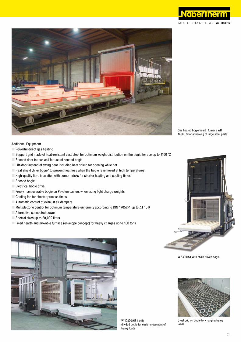
Bogie Hearth Furnaces, Electrically Heated (W) or Gas-Fired (WB) for Annealing
Bogie with chain drive
Cooling fan for shorter process cycles
High-quality fibre insulation with corner bricks for shorter heating and cooling times
For annealing and hardening of large parts, like heavy cast parts or tool steel dies to temperatures between 800 °C and 1�00 °C, we recommend our bogie hearth furnaces with radiation heating. The bogie can be conveniently loaded outside the furnace. With a second door or bogie-transfer system, one bogie can be charged outside the furnace while the other bogie is in the furnace. This way, turnaround time between process cycles will be reduced substantially.
Maximum temperatures of 900 °C or 1�80 °CDouble-walled housing with rear ventilation, provides low shell temperaturesSwing door hinged on the right sideHeating from five sides (four sides and bogie) provides for a uniform temperature distributionAutomatic power connection to the bogie when moved into the furnaceHeating elements mounted on support tubes provide for free radiation and long service lifeFloor heating protected by SiC tiles on the bogie providing level stacking surfaceMulti-layer insulation consisting of lightweight refractory bricks backed by microporus silica insulationSelf-supporting roof archBogie on rails incl. rails in front of the furnace for chargingAdjustable air inlet damperManual vapor vent on the furnace roofFor control system see page 38
W 4700/S with lift-door
Model Tmax Inner dimensions in mm Volume Exterior dimensions in mm Supply Electrical Weight°C w d h in l W D H power/kW connections in kg
W 1000/G 900 800 1600 800 1000 1400 �350 1880 57 3-phase 3000W 1500/G 900 900 1900 900 1500 1500 �650 �010 75 3-phase 3500W ��00/G 900 1000 ��00 1000 ��00 1600 �950 �1�0 110 3-phase 4000W 3300/G 900 1000 �800 1�00 3300 1600 3550 �3�0 140 3-phase 5300W 4100/G 900 1�00 �800 1�00 4040 1800 3550 �350 140 3-phase 5400W 5000/G 900 1000 3600 1400 5000 1600 4350 �5�0 185 3-phase 7500W 7100/G 900 1400 3600 1400 7060 �000 4350 �570 185 3-phase 8500W 7500/G 900 1000 5400 1400 7500 1600 6150 �5�0 �35 3-phase 9100W 8100/G 900 1600 3600 1400 8070 ��00 4350 �590 �75 3-phase 10400W 10000/G 900 1000 7100 1400 10000 1600 7850 �5�0 300 3-phase 11000
W 1000 1�80 800 1600 800 1000 1470 �400 18�0 75 3-phase 3000W 1500 1�80 900 1900 900 1500 1570 �700 �010 110 3-phase 3500W ��00 1�80 1000 ��00 1000 ��00 1670 3000 �1�0 140 3-phase 4000W 3300 1�80 1000 �800 1�00 3300 1670 3600 �3�0 185 3-phase 5300W 4100 1�80 1�00 �800 1�00 4040 1870 3600 �350 185 3-phase 5600W 5000 1�80 1000 3600 1400 5000 1670 4400 �5�0 �35 3-phase 7500W 7100 1�80 1400 3600 1400 7060 �070 4400 �570 �35 3-phase 8800W 7500 1�80 1000 5400 1400 7500 1670 6�00 �5�0 300 3-phase 9100W 8100 1�80 1600 3600 1400 8070 ��70 4400 �590 370 3-phase 10800W 10000 1�80 1000 7100 1400 10000 1670 7900 �5�0 390 3-phase 11000
30
W 4700/S with lift-door
W 6430/S1 with chain driven bogie
Additional EquipmentPowerful direct gas heatingSupport grid made of heat-resistant cast steel for optimum weight distribution on the bogie for use up to 1100 °CSecond door in rear wall for use of second bogieLift-door instead of swing door including heat shield for opening while hotHeat shield „filler bogie” to prevent heat loss when the bogie is removed at high temperaturesHigh-quality fibre insulation with corner bricks for shorter heating and cooling timesSecond bogieElectrical bogie driveFreely maneuverable bogie on Pevolon casters when using light charge weightsCooling fan for shorter process timesAutomatic control of exhaust air dampersMultiple zone control for optimum temperature uniformity according to DIN 1705�-1 up to ΔT 10 KAlternative connected powerSpecial sizes up to �0,000 litersFixed hearth and movable furnace (envelope concept) for heavy charges up to 100 tons
W 10800/HS1 with divided bogie for easier movement of heavy loads
Steel grid on bogie for charging heavy loads
Gas heated bogie hearth furnace WB 14880 S for annealing of large steel parts
31

Rotary Hearth Furnaces for Preheating and Sintering of Molds
Rotary hearth furnaces are used in the area of precision casting. They are used to preheat and sinter molds which have already been dewaxed in autoclaves. This type of furnace is always recommended when the working temperature is maintained continuously and the molds have to be discharged for pouring. A servo motor is installed under the furnace which moves the furnace table at defined time intervals. The movement takes place in predetermined segments which can be specified for each application.
Tmax up to 1000 °CDesigned for continuous operation at one temperatureDiameter up to 3000 mmServo motor under the furnace for movement in defined segmentsSmooth table movementParallel swinging door for charging/dischargingTable movement triggered by a foot pedal, timer or input from another systemVery compact design in comparison with other continuous furnacesElectric heating using wire heating elements mounted in the furnace ceiling
Additional EquipmentMultizone control for adjustable charge temperature profiles during passageHeating with powerful SiC heating rods for Tmax up to 1300 °CFuel heating instead of electric heatingInjection of protective gas for particular applications, such as the heat treatment of stainless steels
Rotary Hearth Furnace DH 630/S
Gear rim drive under the furnace
Exhaust air hood above charging opening
3�

Salt-bath furnaces offer remarkably high temperature uniformity and excellent heat transfer to the work piece. Our salt-bath furnaces TS �0/15 - TS or TSB 70/90 are especially useful for heat-treating of metals in neutral or active salt baths. Processes such as carbonitriding (e.g. Tenifer) up to 600 °C, carburizing up to 950 °C, or bright annealing up to 1000 °C can be realized. In their standard version these furnaces are equipped with safety technology for heat treatment of steel. As addional feature they can be equipped with extended safety technology for heat treatment of light metals.
Standard ModelMaximum temperatures of 750 °C or 1000 °C in the salt bathSafety technology according to EN 60519-�Useful for heat treatment of steelBath temperature controlElectric (TS) all-round heating or gas heating (TSB)Removable collar plate made of solid steelInsulated swing-a-way lidOptimum temperature uniformity according to DIN 1705�-1 up to ΔT 4 K in the bathOver-temperature limit controller in the furnace chamber to prevent dangerous conditions for the furnace or personnelBath control of salt bath and furnace chamber
CruciblesType P: low carbon steel, CrNi plated and corundum coated for carburizing baths up to 950 °C, neutral salt and annealing baths up to 850 °CType C: high alloy CrNi steel for neutral salt and annealing baths up to 1000 °C
Additional EquipmentExhaust gas collection at rim for connection to an exhaust systemCustom dimensionsEnhanced safety systems for heat treatment of aluminium and magnesium in the salt bath with second over-temperature limit controller and PLC-bath control with thermocouples in the salt bath and in the furnace chamber
Salt-Bath Furnaces, electrically (TS) or gas heated (TSB) for Heat Treatment of Steel or Light Metals
Salt bath plant for annealing of aluminum components in the aircraft industry
TS 40/30with exhaust gas collection at crucible rim
TSB 30/30with exhaust gas collection at crucible rim
Model Tmax Inner dimensions crucible Volume Exterior dimensions in mm Supply Electrical Weight°C² Ø in mm h in mm in l W D H power/kW¹ connections in kg¹
TS �0/15 750 �30 500 �0 850 970 800 16 3-phase 650TS 30/18 750 300 500 30 950 1070 800 �0 3-phase 700TS 40/30 750 400 500 60 1050 1170 800 33 3-phase 750TS 50/48 750 500 600 110 1150 1�70 970 58 3-phase 1000TS 60/63 750 610 800 ��0 1�50 1370 1170 70 3-phase 1�00TS 70/7� 750 700 1000 370 1350 1470 1370 80 3-phase 1500
TS, TSB �0/�0 1000 �30 500 �0 850 970 800 �1 3-phase 650TS, TSB 30/30 1000 300 500 30 950 1070 800 33 3-phase 700TS, TSB 40/40 1000 400 500 60 1050 1170 800 44 3-phase 750TS, TSB 50/60 1000 500 600 110 1150 1�70 970 66 3-phase 1000TS, TSB 60/7� 1000 610 800 ��0 1�50 1370 1170 80 3-phase 1�00TS, TSB 70/90 1000 700 1000 370 1350 1470 1370 100 3-phase 1500¹Only for electric version ²Salt bath temperature
33

Tempering Plants for Steel and Aluminum
Fully automatic tempering system for aluminum with � pit furnaces, water bath, and 6 parking places
Removal of the charge basket from solution annealing and transfer to water bath
PC interface for central operation
Fully Automatic Tempering System with Air-Circulating Pit-Furnace S 1780/65 AS for SolutionAnnealing, Water Bath, Lift Conveyor and Pit Furnace S 3180/26AS for Artificial Aging
This tempering system is available for the tempering of aluminum parts with a quenching time of 30 seconds. All functional processes are fully automated. Both, the solution annealing and the artificial aging furnaces are designed as pit furnaces.
To save time, the conveyor unit picks-up the lid of the solution annealing furnace after solution annealing, along with the attached load basket and transports it to the water bath. The lid is then unlinked and conveyed back to the solution annealing furnace. After quenching, the basket is parked in a free spot.
The subsequent artificial aging process also takes place in a pit furnace. Due to the longer period needed for artificial aging, the artificial aging furnace is equipped for the introduction of two baskets, while the solution annealing furnace can only handle one.
The entire heat treatment, including all movements, is fully automated. The PLC controls handle all movement and locking processes. The system automatically detects occupied parking spaces and furnaces and starts the programmed processes according to priority. Charge documentation takes place on an ongoing basis, that is, the loaded basket is documented from the time it is loaded into a parking place until removal after the end of the process.
Systems designPit furnace S 1780/65 AS for solution annealing of one basket, Tmax 650 °C, volume 1780 litersPit furnace S 3180/�6 AS for artificial aging of two baskets, Tmax �60 °C, volume 3180 litersWater bath with powerful circulation and heating, along with control of the water temperatureLinear lift conveyor for all movement processesPLC controls with Nabertherm Control Center (NCC) for temperature regulation, control of all movements, and parallel batch documentation6 parking spots with automatic occupancy detection, loading with forkliftSafety fence around the entire system
34

Fully automated tempering system with two air-circulating bogie hearth furnaces, quench bath, conveyor system, and par-king spots for five charge baskets
Fully Automated Tempering System with Air-Circulating Bogie Hearth Furnace W 2780/60 AS for Soluti-on Annealing, W 2780/26 AS for Artificial Aging, Lift Conveyor, and Heated Water Bath
This tempering system is available for the tempering of T6 aluminum alloys with a quenching time of 10 seconds. All functional processes are fully automated. Both the solution annealing furnace and the artificial aging furnace are mounted on a platform and are designed as bogie hearth furnaces. After solution annealing, the conveyor unit positions itself in front of the furnace, the door opens, the bogie moves out, and the basket is automatically picked-up by the lift conveyor. The bogie moves back into the furnace and the load is quenched in the water bath underneath.
After the quenching process, the basket is lifted back out of the water bath, drips off, and is conveyed to the artificial aging furnace. After artificial aging, the lift conveyor transports the basket to a free parking spot.
The entire heat treatment, including all movements, is fully automated. The PLC controls handle all movement and locking processes. The system automatically detects occupied parking spaces and furnaces and starts the program-med processes according to priority. Charge documentation takes place on an ongoing basis, that it, the loaded basket is documented from its process start in the parking space until removal after the end of the process.
Implementation of the SystemBogie hearth furnace W �780/60 AS for solution annealing, Tmax 600 °C, volume �780 litersBogie hearth furnace W �780/�6 AS for artificial aging, Tmax �60 °C, volume �780 litersWater bath with powerful circulation and heating, along with control of the water temperatureLinear lift conveyor for all movement processesPLC controls with Nabertherm Control Center (NCC) for temperature regulation, control of all movements, and parallel batch documentation5 parking spots with automatic occupancy detection, loading with forkliftSafety fence around the entire system
35

Tempering Systems for Steel and Aluminum
Bogie hearth furnace W 7440/�6 AS for solution annealing and water bath WB �4000/S for quenching
� x S 3570/65 AS for solution annealing
Water bath with powerful circulation pump
Manual Tempering System with Two Air-Circulating Pit Furnaces S 3570/65 AS for Solution Annealing, Water Bath, Bogie Hearth Furnace W 7440/26 AS for Artificial Aging
This tempering system was built for the tempering of aluminum parts for automaotive industry. The movement processes are performed manually using the customer's crane. These solution annealing furnaces are designed as pit furnaces, while the artificial aging furnace is a bogie hearth furnace.
Solution annealing of the components takes place in two pit furnaces with 3570 liter furnace chambers. After the solution annealing process is concluded, the lid of the furnace is opened pneumatically, the basket is removed using the crane, and it is placed into the water bath. For better quench results, the water bath is equipped with a powerful circulation pump.
After quenching, the operator uses the crane to move the load onto the bogie of furnace W 7440/�6 AS for artificial aging. The bogie hearth furnace is equipped with a chain-driven bogie which is moved out of the furnace electrically. The furnace is dimensioned to accept the loads from both solution annealing furnaces.
The furnace has PLC controls for temperature measurement and charge documentation. Every load can be assigned a name or a charge number, which is then stored along with the date.
Design of the System� pit furnaces S 3570/65 AS for solution annealing of one basket each, Tmax 650 °C, volume 3570 litersBogie hearth furnace W 7440/�6 AS for artificial aging of two baskets, Tmax �60 °C, volume 7440 litersWater bath with powerful circulation and heating, along with control of the water temperaturePLC controls with Nabertherm Control Center (NCC) for charge documentation
36

Manual Tempering System for Steel with Top-Hat Furnace H 4263/12S and Water Bath
This tempering system is available for the tempering of 8 meter steel profiles with a quenching time of 30 seconds. The furnace is a top-hat furnace which is loaded with a crane. After heat treatment, the operator positions the crane with attached C-hook in front of the furnace. The furnace is electrohydraulically opened by the operator at 1150 °C and the bogie is moved out of the furnace.
The charge holder on the bogie and the C-hook are designed in such a way that the charge is positioned into the C-hook directly when the bogie drives out. The crane only needs to lift it up. The operator then moves the material over the water bath and lowers it for quenching. After the quenching process, the basket is lifted back out of the water bath, drips dry, and is manually placed onto a free parking spot with the crane.
The system has PLC controls for temperature measurement and charge documentation. Every load can be assigned a name or a charge number, which is then stored along with the date.
Systems DesignTop-hat furnace H 4�63/1�S, Tmax. 1�00 °C, volume 4�60 liters, electrohydraulic hood drive, chain drive for bogieWater bath with powerful circulationPLC controls with Nabertherm Control Center (NCC) for temperature regulation and charge documentationSafety fence around the entire system
Moving furnace table and material under the C hook of the crane
Quenching of steel bars in water
Annealing system with top-hat furnace H 4�63/1�S and water bath
37

Professional Control and Documentation Alternatives
H 3700 with colored graphic presentation of data
Control Center NCC user interface display-ed on a PC
H 1700 with colored, tabular depiction of the data
Graphic printer
HiProSystems Control and DocumentationThis professional control system for single and multi-zone furnaces is based on Siemens hardware and can be adapted and upgraded extensively. HiProSystems control is used when more than two process-dependent functions, such as exhaust dampers, cooling fans, automatic movements, etc., have to be handled during a cycle; when furnaces with more than one zone have to be controlled; when special documentation of each batch is required and when remote telediagnostic service is required. The system is also perfectly suited for controlling multiple furnaces or furnace groups. It is flexible and is easily tailored to your process or documentation needs.
Alternative User InterfacesTouch panel H 700This basic panel accommodates most basic needs and is very easy to use.Touch panel H 1700Firing cycle data and the extra functions activated are clearly displayed in a table. Messages appear as text.Touch panel H 3700All functions and process data are stored and displayed in easy to read charts. The data can be exported through various interfaces (RS �3�, RS 4�� /485, USB, Ethernet TCI/IP, MPI, Profibus) to a local PC or your company network for further processing. A CF card also gives the opportunity for data storage and transfer to a PC with a card reader.Extension Package, PC-based for Control, Visualisation and Documentation Nabertherm Control Center NCCUpgrading the HiProSystems-Control individually into an NCC provides for additional interfaces, operating documentation, and service benefits in particular for controlling furnace groups including charge beyond the furnace itself (quenching tank, cooling station etc.):
Recommended for heat treatment processes with extensive requirements in respect to documentation e.g. for metals, technical ceramics or in the medicine fieldSoftware can be used also in accordance with the AMS 2750 D (NADCAP)Documentation according to the requirements of Food and Drug Administration (FDA), Part 11, EGV 164�/03 possibleCharge data can be read in via barcodesInterface for connection to existing Enterprise Database systems (e.g. SAP, Oracle)Connection to mobile phone network for alarm message transmission via SMSControl from various locations over the networkCalibration of each measuring point for a specific temperature possibleExtendable for calibration of a polygonal line with up to 18 temperatures per measuring point for use at different temperatures e.g for AMS �750 D applications
Controltherm MV Software for Monitoring, Documentation and Control with Standard Con-trollersDocumentation and reproducibility gain increased attention with steadily rising quality standards.The powerful Nabertherm software Controltherm MV provides for an optimum solution for the control anddocumentation of one or more furnaces (furnace data only).
FeaturesSimple installation without specific knowledgeAll Nabertherm controllers with interface connectableTemperature cycles of up to 16 furnaces (also multi-zone controlled) can be archived in manipulation-safe filesRedundant storage on a network server possibleProgramming, archiving and printing of programs and graphicsFree input of descriptive charge data text with comfortable search functionData exportable into Excel format for further evaluationStart/stop of the controller from the local PC400 additional programs storable (only with Nabertherm controllers)Connection of other furnaces/controllers by means of an additional temperature transducer possible and retrofittableExtension of additional measuring points for archiving possible and retrofittable
*not possible in combination with temperature transducer
Temperature RecorderReliable documentation method with a dot printer or continuous pen and up to six measuring points, also availablewith digitally storing graphic printer (e.g. CF card, USB-stick).
38

www.nabertherm.com
MadeinGermany
Technical CeramicsMIM/CIM, Solar, Silicon
Debinding FurnacesSintering FurnacesKilnsLaboratory Furnaces BioceramicsPhotovoltaicsCrystal GrowthCatalytic or Thermal AfterburnersPlant Concepts
www.nabertherm.com
Madein Germany
Ar ts & Craf ts
Furnaces and Accessories
PotteryPorcelain PaintingGlass PaintingFusingDecoratingEnamellingRaku
www.nabertherm.com
MadeinGermany
FurnacesProtective Gas BoxesHardening SystemsQuenching BathsCharging PlatesTongsGlovesCharging BasketsOther Accessories
Heat TreatmentAnnealing, Hardening, Brazing, Forging, Nitriding
Laboratory
Muffl e FurnacesPreheating FurnacesAshing FurnacesTube FurnacesOvensAir Circulation FurnacesChamber FurnacesMelting FurnacesHigh-Temperature FurnacesSintering Furnaces of ZirconiaVacuum FurnacesDental Furnaces
www.nabertherm.com
MadeinGermany
The Nabertherm Product Range – www.nabertherm.com
Arts & CraftsArt is the union of style and technical skill. Good tools are functional and efficient. Are Nabertherm's kilns for pottery, fused glass, painted porcelain, and enamel ware tools or art?
GlassDifferent furnace concepts for annealing, bending slumping, decorating and tempering make Nabertherm your strong partner for the heat treatment of glass and quartz.
Technical Ceramics MIM/CIM, Solar, Silicon/BioCeramicsWire-heated kilns for use up to 1400 °C and MoSi² kilns for use up to 1800 C offer the best value and quality for sintering Technical Ceramics. All are available in sizes from bench-top to walk-in. To remove binders, we offer solutions from our Combi-Furnaces that debind and sinter in the same furnace to specialized systems for binder removal in a specialized atmosphere (e.g. BASF Catamold).
Laboratory/DentalLaboratory furnaces are available for a variety of applications ranging between 30 - 3000 °C. Our standard product range includes muffle, tube, convection, melting, assay, and high temperature furnaces.
Heat Treatment of Metals, Plastics and Surface FinishingWith the furnaces shown in this catalog, Nabertherm offers a wide variety of furnaces and accessories. Please also ask for our catalogs Heat Treatment I + II, which provide more detail.
Continuous furnace D 650/S
39

Headquarters: Nabertherm GmbH · �8865 Lilienthal/Bremen, Germany · Tel +49 (4�98) 9��-0, Fax -101 · [email protected]
www.nabertherm.com
Please visit our website www.nabertherm.com and find out all you want to know about us and our products.
In addition to our current calendar of trade fairs and training dates, there is also the opportunity to get in touch directly with your local sales office or nearest dealer world-wide.
Professional Solutions for:Arts & CraftsGlassCeramicsLaboratory/DentalHeat Treatment of Metals, Plastics and Surface FinishingFoundry
The whole World of Nabertherm: www.nabertherm.com
Reg
No. C
3.5
/09.
08 (e
nglis
ch),
info
rmat
ion
here
in is
sub
ject
to c
hang
e wi
thou
t not
ice.
Nab
erth
erm
ass
umes
no
liabi
lity
for a
ny e
rrors
that
may
app
ear i
n th
is d
ocum
ent.
[email protected]: (+49) 4�98 9��-0Fax: (+49) 4�98 9��-1�9
[email protected]: (+86) �1 6490 �960Fax: (+86) �1 6490 3107
[email protected]: (+33) 1 5356 1800Fax: (+33) 1 5356 1809
[email protected]: (+39) 348 38�0�78Fax: (+39) 055 480835
[email protected]: (+41) 6� �09 6070Fax: (+41) 6� �09 6071
[email protected]: (+44) 19�� 455 5�1Fax: (+44) 19�� 455 �77
[email protected]: (+1) 30� 3�� 3665Fax: (+1) 30� 3�� 3�15
[email protected].: (+34) 93 553 08 87Fax: (+34) 93 583 95 85
Sales and Service Subsidiaries:
Nabertherm GmbHBahnhofstr. �0�8865 Lilienthal, Germany
Nabertherm Shanghai Ltd.150 Lane, No. 158 Pingbei Road, Minhang District�01109 Shanghai, China
Nabertherm S.A.S51 Rue de Presles93531 Aubervilliers, France
Nabertherm Italiavia Trento N° 1750139 Florence, Italy
Nabertherm Schweiz AG Batterieweg 64614 Hägendorf, Switzerland
Nabertherm Ltd.Vigo Place, AldridgeWest Midlands WS9 8YB, United Kingdom
Nabertherm Inc.54 Reads WayNew Castle, DE 197�0, USA
Nabertherm Ibérica, S.L.Av. de les Corts Catalanes 9 - 11Despacho 4E - Entidad 1� - 1308173 Sant Cugat del Vallés (Barcelona), Spain