FOUNDATIONS - ct.upt.ro C2.pdf · § 2.3 Design Approaches In Design Approach 3, the characteristic...
19
FOUNDATIONS Prof.dr.ing Adrian CIUTINA Universitatea Politehnica Timişoara Facultatea de Construcţii Departamentul de Căi de Comunicație Terestre, Fundații și Cadastru - CURS 2 - Basis of Design Bearing Capacity of Foundations
Transcript of FOUNDATIONS - ct.upt.ro C2.pdf · § 2.3 Design Approaches In Design Approach 3, the characteristic...

FOUNDATIONS
Prof.dr.ing Adrian CIUTINA
Universitatea Politehnica Timişoara
Facultatea de Construcţii
Departamentul de Căi de Comunicație Terestre, Fundații și Cadastru
- CURS 2 -
Basis of Design
Bearing Capacity of Foundations

§ 2.3 Design Approaches
The Partial Safety Factors defined in §2.2 can be applied either:
to the uncertainty source of geotechnical design, or
to design (action effects and bearing capacity)
Adrian Ciutina, Foundations
EN 1997-1 proposes three design approaches in geotechnical design,
expressed symbolically by combination of partial safety factors for:
Actions and Action Effects (A)
Material Properties (M)
Resistances (R)
CHAPTER II – BASIS OF DESIGN
Obs: Interpretation for combinations in subsequent approaches: in the Combination
A1 “+” M1 “+” R1 the partial safety factors for actions (A) are combined with the partial
safety factors for materials (M) and with the partial safety factors for resistances (R).

§ 2.3 Design Approaches
In Design Approach 1, the partial safety factors are applied at
source, e.g. on the representative values of actions and on the
characteristic values of Shear resistance of the soil.
Adrian Ciutina, Foundations
Design Approach 1
In DA 1, there are two combinations of partial safety factors:
Combination 1: A1 “+” M1 “+” R1
This combination targets the safety in regard to the unfavorable deviations
for the characteristic values of actions or action effects. The design
properties of soils are close to characteristics values.
Combination 2: A2 “+” M2 “+” R1
This combination targets the safety in regard to the unfavorable deviations
for the characteristic values of actions, resistance parameters of soils and
design model uncertainities.
Obs: The DA1 is recommended for ULS STR and ULS GEO checks.
Exception for Design Approach 1: axially loaded piles and anchors.

§ 2.3 Design Approaches
Values of partial safety factors used in Design Approach 1.
Adrian Ciutina, Foundations
Design Approach 1
Obs: Usually the geotechnical design is made using Combination 1 while the
Structural design uses the Combination 2.
Design Approach 1 Combination 1 Combination 2
A1 M1 R1 A2 M2 R2
permanent Actions (G)
Unfavorable γG 1.35 1.0
Favorable
γG, fav
1.0 1.0
variable Actions (Q) Unfavorable γQ 1.5 1.3
Favorable γQ, fav 0 0
angle of shearing
resistance(tg ϕ) γϕ 1.0 1.25
Effective cohesion (c’) γc' 1.0 1.25
undrained shear strength (cu) γcu 1.0 1.4
unconfined strength (qu) γqu 1.0 1.4
Weight Density (γ) γγ 1.0 1.0
Resistance (R) γR 1.0 1.0

§ 2.3 Design Approaches
In Design Approach 2, the safety of foundations is checked by
applying partial safety factors to actions or action effects and
resistances while the geotechnical parameters are taken with
characteristic values.
Adrian Ciutina, Foundations
Design Approach 2
In DA 2, the following combination is considered:
Combination 1: A1 “+” M1 “+” R2
The values of the partial safety factors for DA2 are given in previous table.
Obs: The DA2 is recommended for ULS of rupture or excessive deformation.
However, the Romanian National Annex does not recommend the use of DA2.

§ 2.3 Design Approaches
In Design Approach 3, the characteristic structural actions are
multiplied with A1 set of factors to offer the design values. The design
values of soil actions (geotechnical actions) are established using partial
safety factors M2 and the set A2 of factors for actions.
Adrian Ciutina, Foundations
Design Approach 3
In DA 3, the following combination is considered:
Combination: (A1*orA2†) “+” M2 “+” R3
* on structural actions
† on geotechnical actions
Obs: The DA3 is recommended for ULS STR and ULS GEO checks.

§ 2.3 Design Approaches
Values of partial safety factors used in Design Approach 3.
Adrian Ciutina, Foundations
Design Approach 3
Design Approach 3 A1 A2 M2 R3
permanent Actions (G)
Unfavorable γG 1.35 1.0
Favorable
γG, fav
1.0 1.0
variable Actions (Q) Unfavorable γQ 1.5 1.3
Favorable γQ, fav 0 0
angle of shearing
resistance(tg ϕ) γϕ 1.25
Effective cohesion (c’) γc' 1.25
undrained shear strength (cu) γcu 1.4
unconfined strength (qu) γqu 1.4
Weight Density (γ) γγ 1.0
Resistance (exception pile
surface in traction)
(R) γR 1.0
Resistance for pile surface
in traction
1.1

§ 3.1 Behaviour of the foundation soil
The bearing capacity of the foundation and the foundation soil
represents the allowable load that can be transmitted to the foundation
base in order to avoid:
excessive settlement of the foundation soil
loss of stability of the foundation – foundation soil.
Adrian Ciutina, Foundations
CHAPTER III – BEARING CAPACITY OF FOUNDATIONS
The loads transmitted to the foundation soils born a stress state
which overlaps the original proper weight of the soils, leading to its
deformation.
Considering the generic foundation (figure
right) loaded by the axial load N, then the soil
pressure, denoted as contact pressure or
effective pressure is given by:

§ 3.1 Behaviour of the foundation soil
Under the force N, the foundation soil will settle (s).
If the force N will continue to increase the following
graph can be drawn by measuring pef and s:
Adrian Ciutina, Foundations
On this graph there can be
distinguished three segments
corresponding to three characteristic
deformation phases under foundation
load.

§ 3.1 Behaviour of the foundation soil
linear behavior: corresponds to the segment 0-1.
The relationship between the deformation
(settlement) and pressure is quasi-linear.
The diagram on this segment can be assimilated
with a straight line.
Considering two differential soil volumes located
on vertical lines delimiting the foundation basis will
compress by contraction of soil pores under
foundation pressure.
Adrian Ciutina, Foundations
The settlements measured for pef<p1 are due
mainly to compaction compaction pahse.
The behavior of the soil in this deformation phase
depends mainly on its deformability characteristics.

§ 3.1 Behaviour of the foundation soil
By increasing the effective pressure (segment 1-2)
the relationship between pressure and deformation
becomes non-linear. In this stage the deformation of
the foundation soil is due in part to compaction and
in part to sliding phenomena: besides volume
variations appear form variations.
Adrian Ciutina, Foundations
By increasing the effective pressure to p2 value,
tangential stresses increase. Thus the shear capacity
of the soil is exceeded: initially in isolated points
finally on plastic zones
This phases is denoted as sliding phase or phase
of development of plastic zones
The pressure corresponding to this phase is
named plasticity pressure ppl or allowable pressure
for the foundation soil.

§ 3.1 Behaviour of the foundation soil
Adrian Ciutina, Foundations
The plasticity pressure ppl represents the
admissible pressure for the foundation soil for which
the extension of the plastic zones is limited.
This values depends on the conditions set for each
soil type (conditions for limiting the extension of the
plastic zones into the foundation soil).
The pressure corresponding to this phase is
named plasticity pressure ppl or allowable pressure
for the foundation soil.
§ 3.1 Behaviour of the foundation soil
Adrian Ciutina, Foundations
At a certain value of the effective pressure
pef=p3=pcr , the foundation soil reaches its bearing
capacity.
In this stage the soil slides on a shear failure
surface.
This phase is denoted as failure phase.
If the effective pressure pef is greater that p2, the
soil deformations are accumulated for small
increments of soil pressure due to the extension of
plastic zones and the formation of failure
mechanisms by shear (sliding surfaces).
For shallow foundations p3 represents the critical
pressure on the foundation soil pcr.

§ 3.2 Failure of the foundation soil
Adrian Ciutina, Foundations
The way of variation of the effective pressure with the soil deformation
and the formation of the soil failure mechanism depends on:
The nature of the foundation soil
Nature of action
Action speed

§ 3.1 Behaviour of the foundation soil
Adrian Ciutina, Foundations
CHAPTER III – BEARING CAPACITY OF FOUNDATIONS

§ 3.2 Failure of the foundation soil
Adrian Ciutina, Foundations
Possible failure modes - general shear:
Characteristic for foundation soils with low compressibility: sands
and compressed gravels, compact clays, stony soils etc.
Under foundation is formed a continuous fracture surface
The soil in the fault behaves elastically

§ 3.2 Failure of the foundation soil
Adrian Ciutina, Foundations
Possible failure modes – punching shear:
Characteristic for foundation soils with high compressibility: loose
sands and gravels, silty clays with low consistency etc.
The foundation penetrates the ground as a piston without affecting
the surrounding soil.
The characteristic behavior has a constant speed of penetration
(no linear behavior)
§ 3.2 Failure of the foundation soil
Adrian Ciutina, Foundations
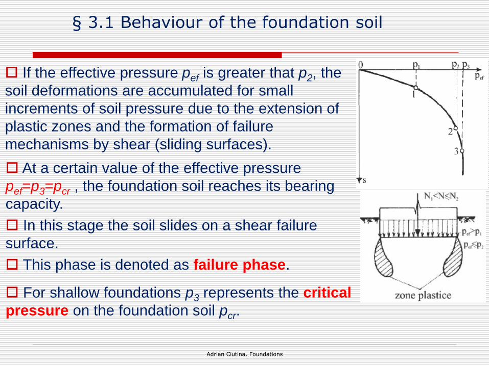
Possible failure modes – local shear:
Characteristic for foundation soils with medium compressibility.
It represents an intermediate failure: although there are tendencies
of lateral shear of the soils, the sliding shears close in the soil
mass without sliding to the ground surface.
In this case the pcr value can be defined through defining a
deformation criterion.
§ 3.3 Bearing capacities according to Romanian norm NP 112-2014
Adrian Ciutina, Foundations
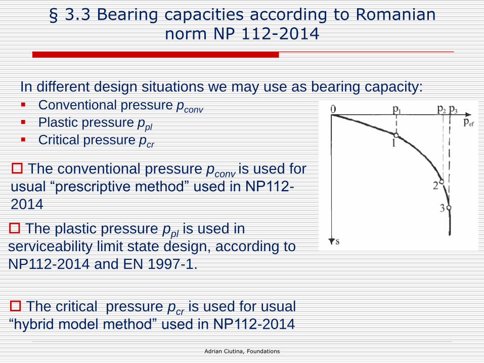
In different design situations we may use as bearing capacity:
Conventional pressure pconv
Plastic pressure ppl
Critical pressure pcr
The conventional pressure pconv is used for
usual “prescriptive method” used in NP112-
2014
The plastic pressure ppl is used in
serviceability limit state design, according to
NP112-2014 and EN 1997-1.
The critical pressure pcr is used for usual
“hybrid model method” used in NP112-2014